Embed Size (px)
Citation preview
Computer Methods and Recent Advances in Geomechanics – Oka, Murakami, Uzuoka & Kimoto (Eds.)© 2015 Taylor & Francis Group, London, ISBN 978-1-138-00148-0
Instability analysis and numerical simulation of the dissociation processof methane hydrate bearing soil
H. Iwai, S. Kimoto, T. Akaki & F. OkaDepartment of Civil and Earth Resources Engineering, Kyoto University, Kyoto, Japan
ABSTRACT: Methane hydrates have been viewed as a new potential energy source, since a large amountof methane gas is trapped inside the hydrates. It is, however, well known that dissociation process of methanehydrate may lead to unstable behavior such as large deformation, uncontrollable gas production etc. A linearinstability analysis was performed in order to investigate which variables have a significant effect on the onsetof the instability of methane hydrate bearing soils with a simplified viscoplastic constitutive equation sub-jected to dissociation. Then, we conducted a numerical analysis of gas hydrate bearing soil with dissociationin order to investigate the effect of the rate of hydrate dissociation on the system. From the numerical results,the larger pore gas pressure and pore water pressure are produced and they diverge when the methane hydratedissociation rate is relatively higher.
1 INTRODUCTION
Recently, methane hydrates have been viewed as apotential energy resource since a large amount ofmethane gas is trapped inside the hydrates. A unitvolume of methane hydrate dissociates into approx-imately 160–170 times of volume of methane gas. Wedo not have, however, enough knowledge about behav-iors of methane hydrates bearing sediments inducedby dissociation. Some researchers have pointed outthat gas hydrates may be a trigger of submarine geo-hazard (e.g., Sultan et al. 2004a, b). Wu et al. (2008)showed the possibility that the dissociation of methanehydrates causes significant increase in the pore pres-sure and thus significant decrease in the effectivestress under undrained conditions through the labo-ratory tests. In addition, many experimental studiesindicate that the loss of bonding effects of hydratesbetween soil particles in sediments may lead to thedecrease in the stiffness and the strength (e.g., Hyodoet al. 2014, Waite et al. 2009). Recently, several numer-ical models that can simulate the flow and deformationbehavior during hydrate dissociation have been devel-oped by many researchers and institutions. Kimotoet al. (2010) have developed a numerical simulatorfor deformation of soil containing methane hydratesin order to predict ground stability during hydratedissociation, in which an elasto-viscoplastic modelconsidering the effect of suction and the hydratesaturation is used for soil sediments. From the numer-ical results, they reported that ground deformation isinduced by generation and dissipation of the waterpressure and the gas pressure, and it localizes aroundthe hydrate dissociation area.
Many experimental and numerical studies havebeen conducted on the deformation behavior associ-ated with methane hydrate dissociation. Nevertheless,few theoretical studies to investigate the onset of insta-bility subjected to hydrate dissociation such as linearstability analysis have been performed. The instabil-ity analysis for a water saturated soil has been widelystudied by many researchers. Rice (1975) investi-gated a stability of fluid saturated porous materialin quasi-static conditions. Anand et al. (1987) andZibib & Aifantis (1988) conducted linear perturbationstability analysis for the onset of shear localization.Oka et al. (1995) have been dealing with the strainlocalization problem of water saturated clay throughthe use of viscoplastic constitutive equations becauseof the rate dependent nature of cohesive soil. Higoet al. (2005) have studied the effect of permeabil-ity and initial heterogeneity on the strain localizationof water saturated soil. Garcia et al. (2010) haveperformed a linear stability analysis in order to inves-tigate which variables have a significant effect onthe onset of the instability of an unsaturated vis-coplastic material subjected to water infiltration. Theyhave found that the onset of growing instability ofthe material system mainly depends on the spe-cific moisture capacity, the suction and the hardeningparameter.
In the present study, we have conducted a linearstability analysis to investigate the onset of instabilityduring dissociation process. Figure 1 shows an illus-tration of the stable and unstable regions of methanehydrate bearing sediments with and without hydratesdissociation. We discuss which parameters or variableshave a significant effect on the instability of methane
421
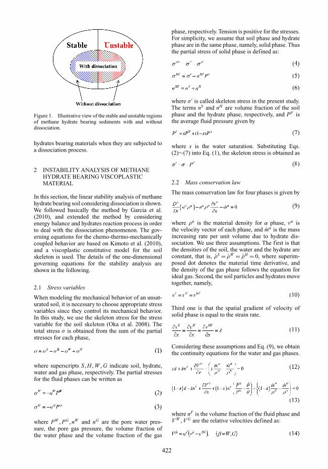
Figure 1. Illustrative view of the stable and unstable regionsof methane hydrate bearing sediments with and withoutdissociation.
hydrates bearing materials when they are subjected toa dissociation process.
2 INSTABILITY ANALYSIS OF METHANEHYDRATE BEARING VISCOPLASTICMATERIAL
In this section, the linear stability analysis of methanehydrate bearing soil considering dissociation is shown.We followed basically the method by Garcia et al.(2010), and extended the method by consideringenergy balance and hydrates reaction process in orderto deal with the dissociation phenomenon. The gov-erning equations for the chemo-thermo-mechanicallycoupled behavior are based on Kimoto et al. (2010),and a viscoplastic constitutive model for the soilskeleton is used. The details of the one-dimensionalgoverning equations for the stability analysis areshown in the following.
2.1 Stress variables
When modeling the mechanical behavior of an unsat-urated soil, it is necessary to choose appropriate stressvariables since they control its mechanical behavior.In this study, we use the skeleton stress for the stressvariable for the soil skeleton (Oka et al. 2008). Thetotal stress σ is obtained from the sum of the partialstresses for each phase,
where superscripts S, H , W , G indicate soil, hydrate,water and gas phase, respectively. The partial stressesfor the fluid phases can be written as
where PW , PG , nW and nG are the pore water pres-sure, the pore gas pressure, the volume fraction ofthe water phase and the volume fraction of the gas
phase, respectively. Tension is positive for the stresses.For simplicity, we assume that soil phase and hydratephase are in the same phase, namely, solid phase. Thusthe partial stress of solid phase is defined as:
where σ ′ is called skeleton stress in the present study.The terms nS and nH are volume fraction of the soilphase and the hydrate phase, respectively, and PF isthe average fluid pressure given by
where s is the water saturation. Substituting Eqs.(2)∼(7) into Eq. (1), the skeleton stress is obtained as
2.2 Mass conservation law
The mass conservation law for four phases is given by
where ρα is the material density for α phase, vα isthe velocity vector of each phase, and mα is the massincreasing rate per unit volume due to hydrate dis-sociation. We use three assumptions. The first is thatthe densities of the soil, the water and the hydrate areconstant, that is, ρS = ρW = ρH = 0, where superim-posed dot denotes the material time derivative, andthe density of the gas phase follows the equation forideal gas. Second, the soil particles and hydrates movetogether, namely,
Third one is that the spatial gradient of velocity ofsolid phase is equal to the strain rate.
Considering these assumptions and Eq. (9), we obtainthe continuity equations for the water and gas phases.
where nF is the volume fraction of the fluid phase andV W , V G are the relative velocities defined as:
422
2.3 Darcy type’s law
Darcy type’s law for the flows of the water and the gascan be described as follows:
where F is the body force such as gravitational forceper unit mass, kW and kG are the permeability coef-ficients for the water and the gas phases, respectively,and g is gravitational acceleration.
2.4 Equilibrium equation
The one-dimensional equilibrium equation can bewritten as:
2.5 Energy conservation law
In the present study, we consider heat conductivityand heat change rate QH associated with the hydratedissociation. The one-dimensional equation of energyconservation is written as:
Where cα and kα are the specific heat and the heatconductivity of phase α, respectively, and θ is temper-ature for all phases, and QH is time rate of dissociationheat per unit volume due to the hydrate dissociation.
2.6 Dissociation rate of methane hydrate
Methane hydrate dissociates into water and gas withthe reaction expressed in Eq. (21).
We use Kim-Bishnoi’s equation for the methanehydrate dissociation rate NH (Kim et al. 1987).
where NH is the moles of hydrates in the volume V ,NH0 is the moles of hydrates in the initial state, Pe isan equilibrium pressure at the temperature θ, and DHis the coefficient of hydrate dissociation rate.
2.7 Viscoplastic constitutive equation
In the numerical simulations, we use the viscoplas-tic constitutive equations taking into account thedependency on the hydrate saturation and the suction(Kimoto et al. 2010), however in the stability anal-ysis, a simplified viscoplastic constitutive model isused for simplicity. The stress-strain relation can beexpressed as
where ε is the strain, ε is the strain rate, H is the strainhardening-softening parameter and µ is the viscoplas-tic parameter. We assume that the strain hardening-softening parameter H is a function of the suction PC
and the hydrate saturation SHr for simplicity. The vis-
coplastic parameter µ is a function of the temperatureθ, namely,
2.8 Perturbed governing equation
In order to estimate the instability of the material sys-tem, we consider the governing equations describedabove in a perturbed configuration. In those equations,the unknowns are the pore water pressure PW , the poregas pressure PG , the strain ε, the temperature θ, and themoles of hydrate NH . For each unknown, we supposethat
where the first terms in right side in Equation (27) indi-cate the values which satisfy the governing equationsand second terms are the perturbations of each vari-ables. For the perturbations, we assume the periodicform as follows:
where q is the wave number, ω is the rate of thefluctuation growth, and superscript ( )∗ indicatesthe amplitude of each variable. Substituting Eq. (27)into Eqs. (12), (13), (17), (18), (22), and consideringEq. (28), the perturbed governing equations can berewritten in matrix form.
423
From the non-zero conditions for the amplitudes, weobtain a following polynomial equation.
When the growth rate of the perturbations ω has a posi-tive real part, the fluctuations grow as time progresses,namely the system becomes unstable. On the contrary,if the real part of ω is negative, the material systemis stable. The necessary and sufficient conditions thatthe all roots have negative real parts are given by theRouth-Hurwitz criteria.
Considering the criteria, if at least one coefficientof Eq. (30) has different sign from others, it is possi-ble that the real part of ω becomes positive, and thematerial system can be unstable. We discuss the signof the coefficient a5 and a0.
where HSH is the partial derivative of H with respectto the hydrate saturation SH
r , namely,
and CN is the partial derivative of NH with respect tothe moles of hydrates NH , namely,
Note that the sign of q, s, n, nF , nH , HSH , kW , kG , kθ ,γW , γG , ρc, CN , b, PG are always positive, whereasthe sign of BC and NH is always negative. The signof the strain ε is positive in expansion and is negativein compression, and the strain rate ε can be positiveor negative. The strain softening-hardening parameterH is positive in viscoplastic hardening and is negativein viscoplastic softening. Considering that the sign ofeach term and Eq. (31), the sign of a5 is always posi-tive, whereas there is a possibility that the sign of a0becomes negative in the following two cases.
The term of kθq2 + NH b is negative when the mag-nitude of hydrate dissociation rate |NH | is larger thankθq2/b, where the instability conditions are given byEq. (35). The condition H − εHSH nH /n2 > 0 is satis-fied in the case of viscoplastic hardening H > 0 with
the compressive strain ε < 0, or with the expansivestrain which satisfies the following inequality.
In contrast, the term of kθq2 + NH b is positive whenthe hydrate dissociation rate |NH | is smaller thankθq2/b. In this case, the instability conditions aregiven in Eq. (36). The condition H − εHSH nH /n2 < 0is satisfied in the case of the viscoplastic softeningH < 0 with the expansive strain ε > 0, or with thecompressive strain ε < 0 which satisfies the followinginequality.
3 NUMERICAL ANALYSIS BY THE MULTIPHASE COUPLED MODEL
We conducted a numerical analysis of gas hydrate bear-ing soil with dissociation in order to investigate theeffect of the rate of hydrate dissociation on the system.
3.1 Initial and boundary conditions
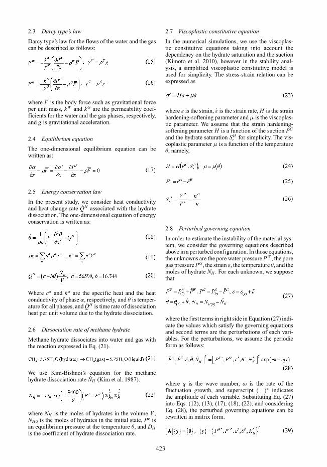
Figure 2 shows the model of seabed ground and thefinite element mesh used in the analysis with bound-ary conditions. The seabed ground from the bottom ofthe seabed to 400 m in depth is modeled under two-dimensional plane strain conditions. The seabed is ata depth of 1000 m. The methane hydrate-bearing layerexists at a ground depth of 264–328 m. We assumethe depressurization method for hydrate dissociation,and the depressurizing source exists in the center ofhydrate layer with length of 32 m.
We apply the hydrostatic pressure at the top, bot-tom, and right boundaries. The left boundary is set tobe adiabatic boundary and impermeable for water and
Figure 2. Finite element mesh and boundary conditions.
424
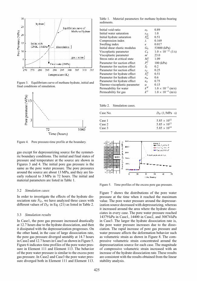
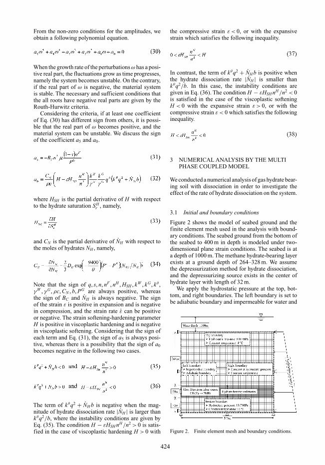
Figure 3. Equilibrium curve of methane hydrate, initial andfinal conditions of simulation.
Figure 4. Pore pressure-time profile at the boundary.
gas except for depressurizing source for the symmet-ric boundary conditions. The initial and final states ofpressure and temperature at the source are shown inFigures 3 and 4. The initial pore gas pressure is thesame as the pore water pressure. The pore pressuresaround the source are about 13 MPa, and they are lin-early reduced to 3 MPa in 72 hours. The initial andmaterial parameters are listed in Table 1.
3.2 Simulation cases
In order to investigate the effects of the hydrate dis-sociation rate NH , we have analyzed three cases withdifferent values of DH in Eq. (21) as listed in Table 2.
3.3 Simulation results
In Case1, the pore gas pressure increased drasticallyat 12.7 hours due to the hydrate dissociation, and thenit dissipated with the depressurization progresses. Onthe other hand, in the case of large dissociation rate,the pore gas pressure diverged unstably at 14.7 hoursin Case2 and 12.7 hours in Case3 as shown in Figure 5.Figure 6 indicates time profiles of the pore water pres-sure in Element 111 and Element 113. The behaviorof the pore water pressure is similar to the excess poregas pressure. In Case2 and Case3 the pore water pres-sure diverged both in Element 111 and Element 113.
Table 1. Material parameters for methane hydrate-bearingsediments.
Initial void ratio e0 0.89Initial water saturation sr0 1.0Initial hydrate saturation SH
r0 0.51Compression index λ 0.169Swelling index κ 0.017Initial shear elastic modulus G0 53800 (kPa)Viscoplastic parameter C0 1.0 × 10⁻¹² (1/s)Viscoplastic parameter m′ 23.0Stress ratio at critical state M ∗
f 1.09Parameter for suction effect PC
i 100 (kPa)Parameter for suction effect SI 0.2Parameter for suction effect sd 0.25Parameter for hydrate effect SH
ri 0.51Parameter for hydrate effect nm 0.6Parameter for hydrate effect nd 0.75Thermo-viscoplastic parameter α 0.15Permeability for water kW 1.0 × 10⁻⁵ (m/s)Permeability for gas kG 1.0 × 10⁻⁴ (m/s)
Table 2. Simulation cases.
Case No. DH (1/MPa · s)
Case 1 5.85 × 10¹²
Case 2 5.85 × 10¹³
Case 3 5.85 × 10¹⁴
Figure 5. Time profiles of the excess pore gas pressure.
Figure 7 shows the distributions of the pore waterpressure at the time when it reached the maximumvalue. The pore water pressure around the depressur-ization source decreased with depressurizing, whereasit increased around the area where the hydrate disso-ciates in every case. The pore water pressure reached14379 kPa in Case1, 14400 in Case2, and 30874 kPain Case3. The larger the hydrate dissociation rate is,the pore water pressure increases due to the disso-ciation. The rapid increase of pore gas pressure andwater pressure affects the deformation behavior suchas volumetric strain as shown in Figure 8. The com-pressive volumetric strain concentrated around thedepressurization source for each case. The magnitudeof compressive volumetric strain increased with anincrease of the hydrate dissociation rate. These resultsare consistent with the results obtained from the linearstability analysis.
425
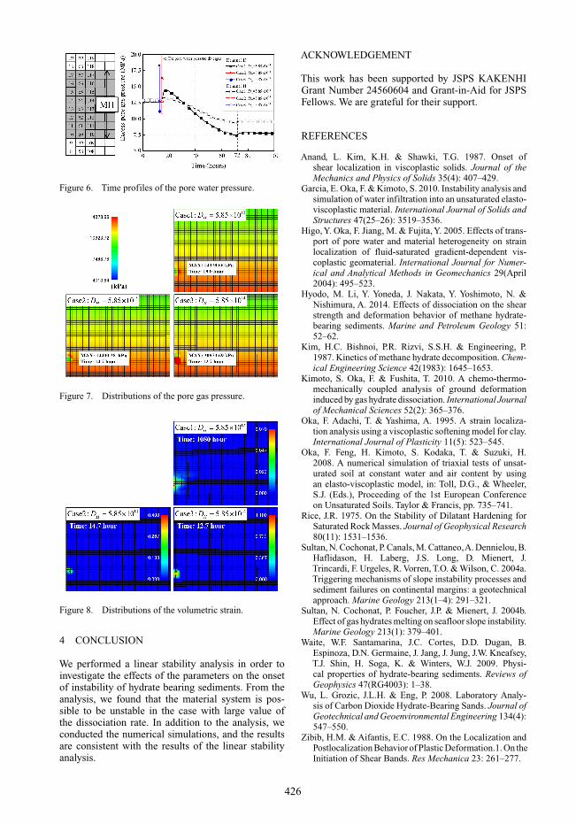
Figure 6. Time profiles of the pore water pressure.
Figure 7. Distributions of the pore gas pressure.
Figure 8. Distributions of the volumetric strain.
4 CONCLUSION
We performed a linear stability analysis in order toinvestigate the effects of the parameters on the onsetof instability of hydrate bearing sediments. From theanalysis, we found that the material system is pos-sible to be unstable in the case with large value ofthe dissociation rate. In addition to the analysis, weconducted the numerical simulations, and the resultsare consistent with the results of the linear stabilityanalysis.
ACKNOWLEDGEMENT
This work has been supported by JSPS KAKENHIGrant Number 24560604 and Grant-in-Aid for JSPSFellows. We are grateful for their support.
REFERENCES
Anand, L. Kim, K.H. & Shawki, T.G. 1987. Onset ofshear localization in viscoplastic solids. Journal of theMechanics and Physics of Solids 35(4): 407–429.
Garcia, E. Oka, F. & Kimoto, S. 2010. Instability analysis andsimulation of water infiltration into an unsaturated elasto-viscoplastic material. International Journal of Solids andStructures 47(25–26): 3519–3536.
Higo, Y. Oka, F. Jiang, M. & Fujita, Y. 2005. Effects of trans-port of pore water and material heterogeneity on strainlocalization of fluid-saturated gradient-dependent vis-coplastic geomaterial. International Journal for Numer-ical and Analytical Methods in Geomechanics 29(April2004): 495–523.
Hyodo, M. Li, Y. Yoneda, J. Nakata, Y. Yoshimoto, N. &Nishimura, A. 2014. Effects of dissociation on the shearstrength and deformation behavior of methane hydrate-bearing sediments. Marine and Petroleum Geology 51:52–62.
Kim, H.C. Bishnoi, P.R. Rizvi, S.S.H. & Engineering, P.1987. Kinetics of methane hydrate decomposition. Chem-ical Engineering Science 42(1983): 1645–1653.
Kimoto, S. Oka, F. & Fushita, T. 2010. A chemo-thermo-mechanically coupled analysis of ground deformationinduced by gas hydrate dissociation. International Journalof Mechanical Sciences 52(2): 365–376.
Oka, F. Adachi, T. & Yashima, A. 1995. A strain localiza-tion analysis using a viscoplastic softening model for clay.International Journal of Plasticity 11(5): 523–545.
Oka, F. Feng, H. Kimoto, S. Kodaka, T. & Suzuki, H.2008. A numerical simulation of triaxial tests of unsat-urated soil at constant water and air content by usingan elasto-viscoplastic model, in: Toll, D.G., & Wheeler,S.J. (Eds.), Proceeding of the 1st European Conferenceon Unsaturated Soils. Taylor & Francis, pp. 735–741.
Rice, J.R. 1975. On the Stability of Dilatant Hardening forSaturated Rock Masses. Journal of Geophysical Research80(11): 1531–1536.
Sultan, N. Cochonat, P. Canals, M. Cattaneo,A. Dennielou, B.Haflidason, H. Laberg, J.S. Long, D. Mienert, J.Trincardi, F. Urgeles, R. Vorren, T.O. & Wilson, C. 2004a.Triggering mechanisms of slope instability processes andsediment failures on continental margins: a geotechnicalapproach. Marine Geology 213(1–4): 291–321.
Sultan, N. Cochonat, P. Foucher, J.P. & Mienert, J. 2004b.Effect of gas hydrates melting on seafloor slope instability.Marine Geology 213(1): 379–401.
Waite, W.F. Santamarina, J.C. Cortes, D.D. Dugan, B.Espinoza, D.N. Germaine, J. Jang, J. Jung, J.W. Kneafsey,T.J. Shin, H. Soga, K. & Winters, W.J. 2009. Physi-cal properties of hydrate-bearing sediments. Reviews ofGeophysics 47(RG4003): 1–38.
Wu, L. Grozic, J.L.H. & Eng, P. 2008. Laboratory Analy-sis of Carbon Dioxide Hydrate-Bearing Sands. Journal ofGeotechnical and Geoenvironmental Engineering 134(4):547–550.
Zibib, H.M. & Aifantis, E.C. 1988. On the Localization andPostlocalization Behavior of Plastic Deformation.1. On theInitiation of Shear Bands. Res Mechanica 23: 261–277.
426