Embed Size (px)
Citation preview
Large eddy simulation study of combustion
instabilities in gas turbines
By Jianguo Wang
Supervisor: Dr Philip A. Rubini
Presentation on 10th ECCRIA
European Conference on Coal Research and its Applications
Large Eddy Simulation of Combustion Instability in
Gas Turbine Engines
1
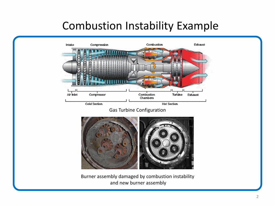
Combustion Instability Example
Burner assembly damaged by combustion instability and new burner assembly
Gas Turbine Configuration
2
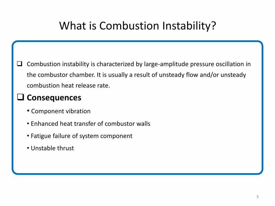
What is Combustion Instability?
Combustion instability is characterized by large-amplitude pressure oscillation in
the combustor chamber. It is usually a result of unsteady flow and/or unsteady
combustion heat release rate.
Consequences
• Component vibration
• Enhanced heat transfer of combustor walls
• Fatigue failure of system component
• Unstable thrust
3
Multi-Perforated Walls
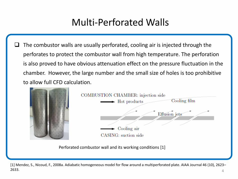
The combustor walls are usually perforated, cooling air is injected through the
perforates to protect the combustor wall from high temperature. The perforation
is also proved to have obvious attenuation effect on the pressure fluctuation in the
chamber. However, the large number and the small size of holes is too prohibitive
to allow full CFD calculation.
Perforated combustor wall and its working conditions [1]
[1] Mendez, S., Nicoud, F., 2008a. Adiabatic homogeneous model for flow around a multiperforated plate. AIAA Journal 46 (10), 2623–2633. 4
Aims and Objectives
• Validate CFD’s capability in predicting pressure fluctuation in unstable flow
• Find a method to account for the perforated walls rather than solving for the tiny
holes
• The Final Aim: Complete CFD simulation of gas turbine combustors
• Background: Experimental design is too expensive and time-consuming
5
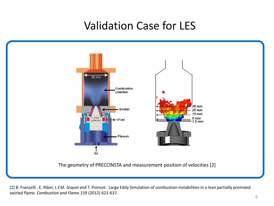
Validation Case for LES
The geometry of PRECCINSTA and measurement position of velocities [2]
[2] B. Franzelli , E. Riber, L.Y.M. Giquel and T. Poinsot. Large Eddy Simulation of combustion instabilities in a lean partially premixed swirled flame. Combustion and Flame.159 (2012) 621-637.
6
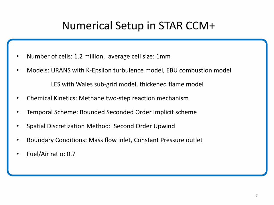
Numerical Setup in STAR CCM+
• Number of cells: 1.2 million, average cell size: 1mm
• Models: URANS with K-Epsilon turbulence model, EBU combustion model
LES with Wales sub-grid model, thickened flame model
• Chemical Kinetics: Methane two-step reaction mechanism
• Temporal Scheme: Bounded Seconded Order Implicit scheme
• Spatial Discretization Method: Second Order Upwind
• Boundary Conditions: Mass flow inlet, Constant Pressure outlet
• Fuel/Air ratio: 0.7
7
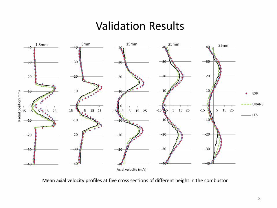
Validation Results
Mean axial velocity profiles at five cross sections of different height in the combustor
-40
-30
-20
-10
0
10
20
30
40
-15 -5 5 15 25
5mm
-40
-30
-20
-10
0
10
20
30
40
-15 -5 5 15 25
Axial velocity (m/s)
15mm
-40
-30
-20
-10
0
10
20
30
40
-15 -5 5 15 25
25mm
-40
-30
-20
-10
0
10
20
30
40
-15 -5 5 15 25
Rad
ial p
osi
tio
n(m
m)
1.5mm
-40
-30
-20
-10
0
10
20
30
40
-15 -5 5 15 25
EXP
URANS
LES
35mm
8
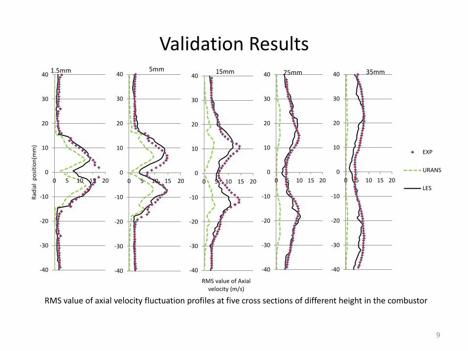
Validation Results
RMS value of axial velocity fluctuation profiles at five cross sections of different height in the combustor
9
-40
-30
-20
-10
0
10
20
30
40
0 5 10 15 20
-40
-30
-20
-10
0
10
20
30
40
0 5 10 15 20
RMS value of Axial velocity (m/s)
15mm
-40
-30
-20
-10
0
10
20
30
40
0 5 10 15 20
25mm
-40
-30
-20
-10
0
10
20
30
40
0 5 10 15 20
Rad
ial
po
siti
on
(mm
)
1.5mm
-40
-30
-20
-10
0
10
20
30
40
0 5 10 15 20
EXP
URANS
LES
35mm
5mm
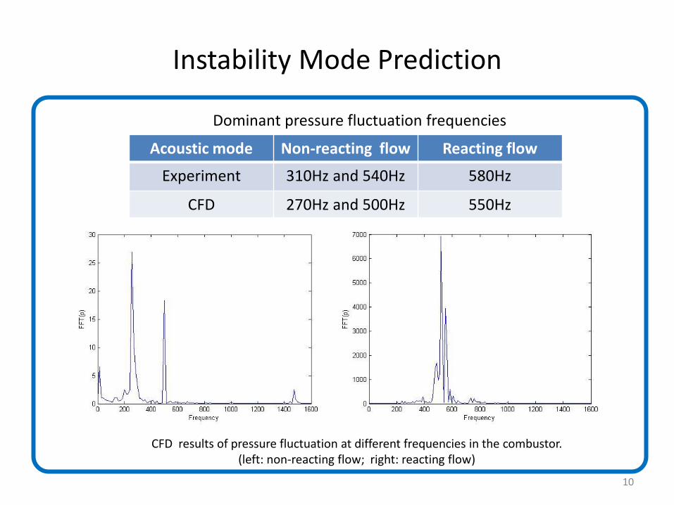
Instability Mode Prediction
CFD results of pressure fluctuation at different frequencies in the combustor. (left: non-reacting flow; right: reacting flow)
Acoustic mode Non-reacting flow Reacting flow
Experiment 310Hz and 540Hz 580Hz
CFD 270Hz and 500Hz 550Hz
Dominant pressure fluctuation frequencies
10
Perforated Wall Treatment(others’ work)
Mendez et al. [1] in 2008, proposed a uniform wall model to account for effusion
cooling effect. This model is rather complex and hard to integrate with CFD
software. Its acceptability to reflect the noise attenuation effect is still open for
validation.
Jourdain et al. [3] in 2014, developed a model based on URANS solver but it would
not work with LES solver which we will use to predict the pressure fluctuation.
[1] Mendez, S., Nicoud, F., 2008a. Adiabatic homogeneous model for flow around a multiperforated plate. AIAA Journal 46 (10), 2623–2633. [3]Jourdain, G., Eriksson, L. Numerical Validation of a Time Domain Perforated Plate Model with Nonlinear and Inertial Effects. J. Comput. Acoust, May,2014. 11
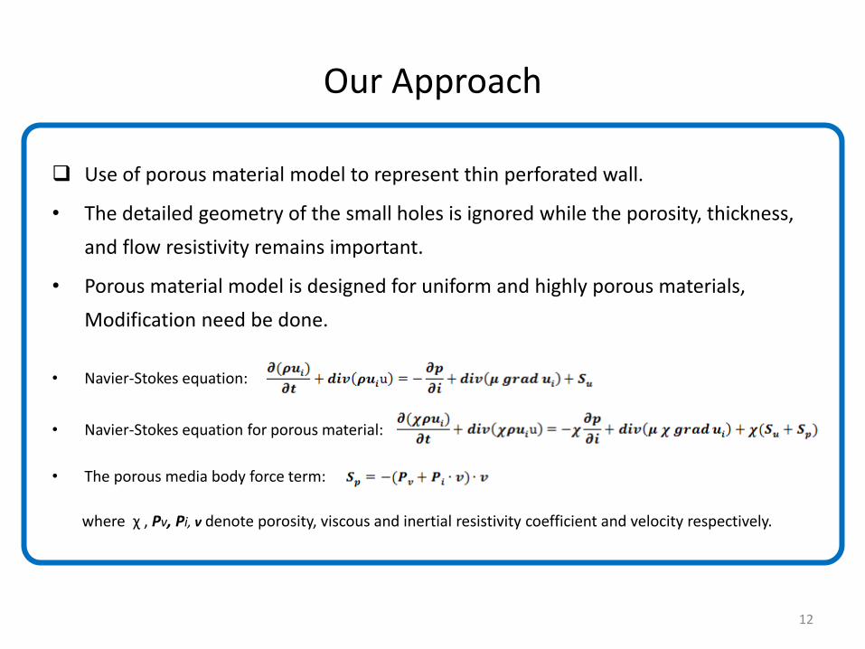
Our Approach
Use of porous material model to represent thin perforated wall.
• The detailed geometry of the small holes is ignored while the porosity, thickness,
and flow resistivity remains important.
• Porous material model is designed for uniform and highly porous materials,
Modification need be done.
• Navier-Stokes equation:
• Navier-Stokes equation for porous material:
• The porous media body force term:
where χ , Pv, Pi, ν denote porosity, viscous and inertial resistivity coefficient and velocity respectively.
12
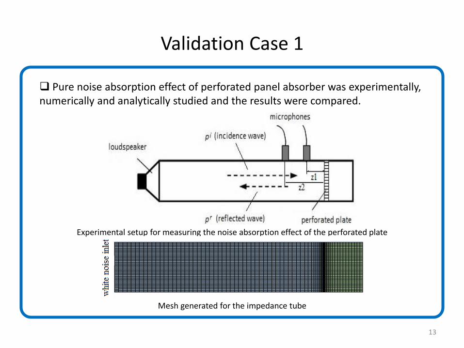
Validation Case 1
Experimental setup for measuring the noise absorption effect of the perforated plate
Pure noise absorption effect of perforated panel absorber was experimentally, numerically and analytically studied and the results were compared.
Mesh generated for the impedance tube
13
Numerical Setup in ANSYS FLUENT
• Cells number: 91,000
• Models: Laminar flow, porous material model
• Temporal scheme: Bounded Second Order Implicit scheme
• Spatial discretization method: Second Order Upwind
• Boundary condition: Pressure far-field white noise inlet
14
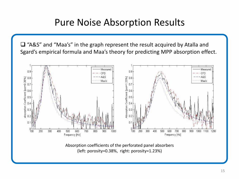
Pure Noise Absorption Results
Absorption coefficients of the perforated panel absorbers (left: porosity=0.38%, right: porosity=1.23%)
“A&S” and “Maa’s” in the graph represent the result acquired by Atalla and Sgard’s empirical formula and Maa’s theory for predicting MPP absorption effect.
15
Validation Case 2
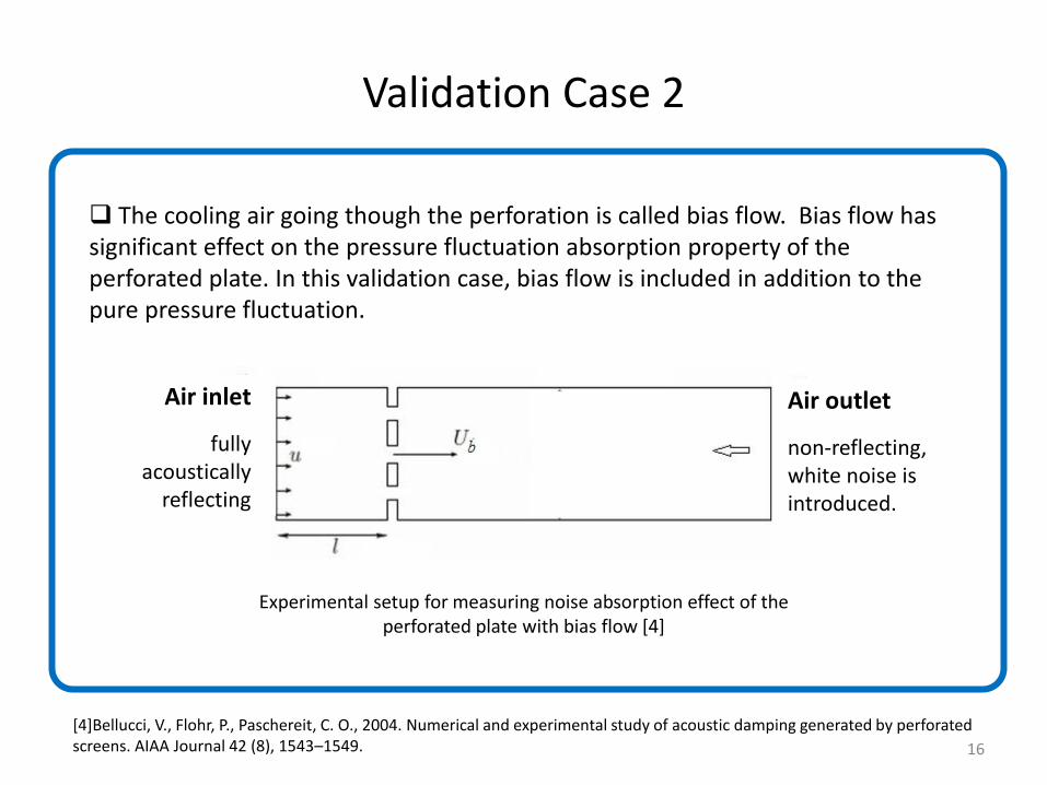
Experimental setup for measuring noise absorption effect of the perforated plate with bias flow [4]
The cooling air going though the perforation is called bias flow. Bias flow has significant effect on the pressure fluctuation absorption property of the perforated plate. In this validation case, bias flow is included in addition to the pure pressure fluctuation.
Air inlet
fully acoustically
reflecting
Air outlet
non-reflecting, white noise is introduced.
[4]Bellucci, V., Flohr, P., Paschereit, C. O., 2004. Numerical and experimental study of acoustic damping generated by perforated screens. AIAA Journal 42 (8), 1543–1549. 16
Noise Absorption with Bias Flow
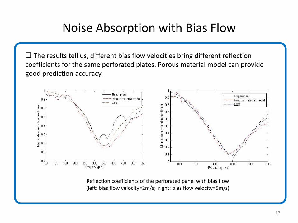
Reflection coefficients of the perforated panel with bias flow (left: bias flow velocity=2m/s; right: bias flow velocity=5m/s)
The results tell us, different bias flow velocities bring different reflection coefficients for the same perforated plates. Porous material model can provide good prediction accuracy.
17
Future Work
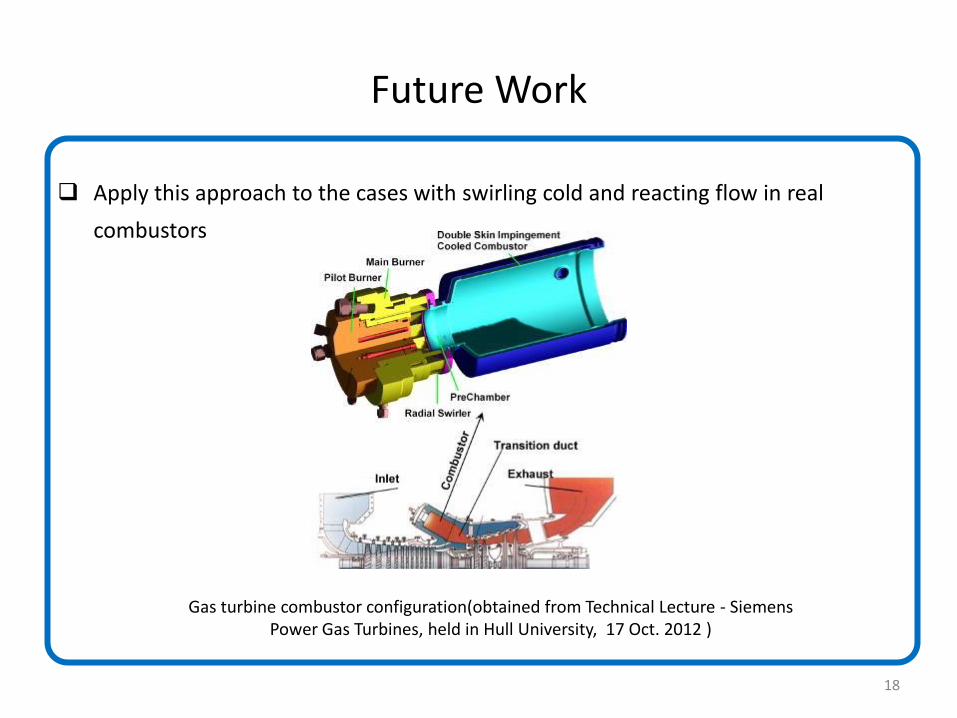
Apply this approach to the cases with swirling cold and reacting flow in real
combustors
Gas turbine combustor configuration(obtained from Technical Lecture - Siemens Power Gas Turbines, held in Hull University, 17 Oct. 2012 )
18
19