Embed Size (px)
Citation preview

PENNSYLVANIA DEPARTMENT OF TRANSPORTATION
BUREAU OF PROJECT DELIVERY
BRIDGE DESIGN & TECHNOLOGY DIVISION
STRUCTURAL MATERIALS SECTION
PUB 145 (12-12)
Inspection of Prestressed/Precast Concrete
Products and Reinforced Concrete Pipe
www.dot.state.pa.us

I
TABLE OF CONTENTS
PART 1 - INSPECTION OF PRESTRESSED / PRECAST CONCRETE PRODUCTS ANDCONCRETE PIPE . . . . . . . . . . . . . . . . . . . . . . . . . . . . . . . . . . . . . . . . . . . . . . . . . . . . . . . . . . . . . . . . . . . .1
SECTION 1 – INTRODUCTION . . . . . . . . . . . . . . . . . . . . . . . . . . . . . . . . . . . . . . . . . . . . . . . . . . . . . .1
SECTION II – GENERAL REQUIREMENTS . . . . . . . . . . . . . . . . . . . . . . . . . . . . . . . . . . . . . . . . . . . .1
SECTION III – INSPECTION OF PRESTRESSED CONCRETE . . . . . . . . . . . . . . . . . . . . . . . . . . . . .3
SECTION IV - CONCRETE PIPE – (Refer also to Publication 280) . . . . . . . . . . . . . . . . . . . . . . . . .8
SECTION V – PRECAST CONCRETE UNITS . . . . . . . . . . . . . . . . . . . . . . . . . . . . . . . . . . . . . . . . .10
SECTION VI – WELDING . . . . . . . . . . . . . . . . . . . . . . . . . . . . . . . . . . . . . . . . . . . . . . . . . . . . . . . . . .10
SECTION VII - MIx DESIGNS: APPROVAL, REVISIONS AND SUBSTITUTIONS
AND TOLERANCES . . . . . . . . . . . . . . . . . . . . . . . . . . . . . . . . . . . . . . . . . . . . . . . . . . . . . . . . . . .11
SECTION VIII - PRODUCTION, SHIPPING AND INVENTORY CONTROL OF STANDARD
(STOCK) PRECAST CONCRETE PRODUCTS . . . . . . . . . . . . . . . . . . . . . . . . . . . . . . . . . . . . . .12
PART 2 - FORM OF INSPECTION REPORTS . . . . . . . . . . . . . . . . . . . . . . . . . . . . . . . . . . . . . . . . . . . . .14
SECTION I – FORM TR-4220c, INSPECTION CHARGES . . . . . . . . . . . . . . . . . . . . . . . . . . . . . . . .14
SECTION II – ELECTRONIC REPORTING – SHOP REPORTS . . . . . . . . . . . . . . . . . . . . . . . . . . . .14
SECTION III – MISCELLANEOUS REPORT . . . . . . . . . . . . . . . . . . . . . . . . . . . . . . . . . . . . . . . . . . .14
TABLE “A” PRESTRESSED/PRECAST CONCRETE PRODUCT INSPECTION
RESPONSIBILITIES . . . . . . . . . . . . . . . . . . . . . . . . . . . . . . . . . . . . . . . . . . . . . . . . . . . . . . . . . . .17
PART 3: SAMPLE FORMS . . . . . . . . . . . . . . . . . . . . . . . . . . . . . . . . . . . . . . . . . . . . . . . . . . . . . . . . . . . .20
Sample Identification TR-447 . . . . . . . . . . . . . . . . . . . . . . . . . . . . . . . . . . . . . . . . . . . . . . . . . . . . . .21
Notice of Approval and Shipment of Prestressed Concrete Bridge Beams – Form TR-4218 . .25
Notice of Inspection and Approval of Prestressed Concrete Beams or Fabricated
Structural Steel – FORM CS-439 . . . . . . . . . . . . . . . . . . . . . . . . . . . . . . . . . . . . . . . . . . . . . . . .26
Quality Report – Form TR 443 . . . . . . . . . . . . . . . . . . . . . . . . . . . . . . . . . . . . . . . . . . . . . . . . . . . . .27
Payment Authorization for Material Stored or On Hand – Form CS-110 . . . . . . . . . . . . . . . . . .28
Dimensional Review for Barrier – 52” Glare Screen – Form TR-1 . . . . . . . . . . . . . . . . . . . . . . . .29
Dimensional Review for Barrier – 34” & 41” Median Single Face – Form TR-2 . . . . . . . . . . . . .30
Dimensional Review for Barrier – 34” Median Double Face – Form TR-3 . . . . . . . . . . . . . . . . . .31
Dimensional Review for JJ-Hook Barrier – Form TR-5 . . . . . . . . . . . . . . . . . . . . . . . . . . . . . . . . .32
Dimensional Review for Manholes – Form TR-4 . . . . . . . . . . . . . . . . . . . . . . . . . . . . . . . . . . . . . .33
RC 46M Dimensional Review for Precast Inlet Base – Form TR-6 . . . . . . . . . . . . . . . . . . . . . . . .34
RC 46M Dimensional Review for Precast Inlet Riser – Form TR-7 . . . . . . . . . . . . . . . . . . . . . . . .35
RC 46M Dimensional Review for Precast Inlet Top or Transitional Slab – Form TR-8 . . . . . . . .36
RC 45M Dimensional Review For Precast Inlet Type D- H – Form TR-9 . . . . . . . . . . . . . . . . . . .37
RC 45M Dimensional Review for Precast Inlet Type D-H Level – Form TR-10 . . . . . . . . . . . . . .38
RC 45M Dimensional Review For Precast Inlet Top Type C & C Alternate – Form TR-11 . . . . .39
RC 45M Dimensional Review For Precast Inlet Top Type M – Form TR-12 . . . . . . . . . . . . . . . . .40

II
RC 45M Dimensional Review For Precast Inlet Top Type S – Form TR-13 . . . . . . . . . . . . . . . . .41
RC 81M Dimensional Review For Precast Light Duty Junction Box JB1/JB2 – Form TR-14 . .42
RC 82M Dimensional Review For Precast Heavy Duty Junction Box JB11/JB12
– Form TR-15 . . . . . . . . . . . . . . . . . . . . . . . . . . . . . . . . . . . . . . . . . . . . . . . . . . . . . . . . . . . . . . .43
Dimensional Review for Precast “D” Endwall – Form TR-16 . . . . . . . . . . . . . . . . . . . . . . . . . . . .44
Dimensional Review for Precast “D-E” Endwall – Form TR-17 . . . . . . . . . . . . . . . . . . . . . . . . . .45
Dimensional Review for Precast “D-W” Endwall – Form TR-18 . . . . . . . . . . . . . . . . . . . . . . . . . .46
Dimensional Review for Precast “E-S” Endwall – Form TR-19 . . . . . . . . . . . . . . . . . . . . . . . . . .47
Dimensional Review for Precast Subsurface Drain Outlet Endwall – Form TR-20 . . . . . . . . . . .48
Dimensional Review for Precast Sound Barrier – Form TR-21 . . . . . . . . . . . . . . . . . . . . . . . . . .49
Dimensional Review for Reinforced Concrete Pipe – Form TR-22 . . . . . . . . . . . . . . . . . . . . . . .50
Dimensional Review For Prestressed Adjacent Box Beams – Form TR-23 . . . . . . . . . . . . . . . .51
Dimensional Review For Prestressed Spread Box Beams – Form TR-24 . . . . . . . . . . . . . . . . . .52
Dimensional Review For Prestressed I-Beam – Form TR-25 . . . . . . . . . . . . . . . . . . . . . . . . . . . .53
Dimensional Review for Precast Next Beam – Form TR-26 . . . . . . . . . . . . . . . . . . . . . . . . . . . . .54
Dimensional Review for Prestressed Next Beam – Form TR-27 . . . . . . . . . . . . . . . . . . . . . . . . .56
Dimensional Review For Box Culvert – Form TR-28 . . . . . . . . . . . . . . . . . . . . . . . . . . . . . . . . . . .58
Dimensional Review For MSE Wall Panels – Form TR-29 . . . . . . . . . . . . . . . . . . . . . . . . . . . . . . .59
Dimensional Review for Parapet Barrier – Form TR-30 . . . . . . . . . . . . . . . . . . . . . . . . . . . . . . . .60
Dimensional Review for T-Wall – Form TR-31 . . . . . . . . . . . . . . . . . . . . . . . . . . . . . . . . . . . . . . . .61
Dimensional Review for Dura-Hold Units – Form TR-32 . . . . . . . . . . . . . . . . . . . . . . . . . . . . . . . .62
Dimensional Review Super Slab – Form TR-33 . . . . . . . . . . . . . . . . . . . . . . . . . . . . . . . . . . . . . . .63
Dimensional Review for Inverset – Form TR-34 . . . . . . . . . . . . . . . . . . . . . . . . . . . . . . . . . . . . . . .65
Dimensional Review for Con/Span Arch Structure – Form TR-35 . . . . . . . . . . . . . . . . . . . . . . . .67
PART 4 APPENDICES . . . . . . . . . . . . . . . . . . . . . . . . . . . . . . . . . . . . . . . . . . . . . . . . . . . . . . . . . . . . . . .68
Repair Procedures for Precast Concrete Products . . . . . . . . . . . . . . . . . . . . . . . . . . . . . . . . . . . .68
ACCEPTANCE AND REPAIR OF PRESTRESSED CONCRETE BEAMS WITH CRACKSAND OTHER REPAIRS . . . . . . . . . . . . . . . . . . . . . . . . . . . . . . . . . . . . . . . . . . . . . . . . . . . . . . . .73
QUALITY CONTROL PLAN GUIDELINES FOR PRECAST AND PRESTRESSEDCONCRETE PLANTS . . . . . . . . . . . . . . . . . . . . . . . . . . . . . . . . . . . . . . . . . . . . . . . . . . . . . . . . . .86
PRODUCTION TOLERANCES . . . . . . . . . . . . . . . . . . . . . . . . . . . . . . . . . . . . . . . . . . . . . . . . . . . . .89
A1 - 52” Glare Screen Tolerances . . . . . . . . . . . . . . . . . . . . . . . . . . . . . . . . . . . . . . . . . . . . . . . . . .90
B1/B3 - 34” & 41” Single Face Median Barrier Tolerances . . . . . . . . . . . . . . . . . . . . . . . . . . . . . .92
B2 - 34” Double Face Median Barrier Tolerances . . . . . . . . . . . . . . . . . . . . . . . . . . . . . . . . . . . . .95
C - Precast Manhole Tolerances . . . . . . . . . . . . . . . . . . . . . . . . . . . . . . . . . . . . . . . . . . . . . . . . . . .97
D1/D2/D3/D4 - Precast Inlet Tolerances for Rehab Projects . . . . . . . . . . . . . . . . . . . . . . . . . . . . .99
D5/D6 - Precast Types C & C Alt. Inlet Top Unit Tolerances for Rehab Projects . . . . . . . . . . .101
D7 - Precast Type M Inlet Top Unit Tolerances for Rehab Projects . . . . . . . . . . . . . . . . . . . . . .103
D8 - Precast Type S Inlet Top Unit Tolerances for Rehab Projects . . . . . . . . . . . . . . . . . . . . . .105
E1/E2 - Precast Light Duty Junction Box Tolerances JB1/JB2 . . . . . . . . . . . . . . . . . . . . . . . . .107

III
E3/E4 - Precast Heavy Duty Junction Box Tolerances JB11/JB12 . . . . . . . . . . . . . . . . . . . . . . .109
F1 - Precast “D” Endwall . . . . . . . . . . . . . . . . . . . . . . . . . . . . . . . . . . . . . . . . . . . . . . . . . . . . . . . .111
F2 - Precast “D-E” Endwall . . . . . . . . . . . . . . . . . . . . . . . . . . . . . . . . . . . . . . . . . . . . . . . . . . . . . .113
F3 - Precast “D-W” Endwall . . . . . . . . . . . . . . . . . . . . . . . . . . . . . . . . . . . . . . . . . . . . . . . . . . . . . .115
F4 - Precast “E-S” Endwall . . . . . . . . . . . . . . . . . . . . . . . . . . . . . . . . . . . . . . . . . . . . . . . . . . . . . . .117
F5 - Precast Subsurface Drain Tolerances . . . . . . . . . . . . . . . . . . . . . . . . . . . . . . . . . . . . . . . . . .119
G1 - Precast Sound Barrier Post Tolerances . . . . . . . . . . . . . . . . . . . . . . . . . . . . . . . . . . . . . . . .121
G2 - Precast Sound Barrier Panel Tolerances . . . . . . . . . . . . . . . . . . . . . . . . . . . . . . . . . . . . . . .123
Production Joint Welding Procedure Specification . . . . . . . . . . . . . . . . . . . . . . . . . . . . . . . . . .125
Local Government/Commercial Stock EQMS Transfer Worksheet – Form TR-38 . . . . . . . . . .127

IV
PREFACE
In February 2004, the Department introduced a comprehensive fabricationinspection documentation application, hereafter referred to as theElectronic Quality Management System (EQMS). This inspection manualhas been revised around the premise that the inspection reporting processis now completely electronic. The intent of this manual is not to providedetails or training for using the EQMS application; that information isavailable through separate training guides and help menus within theapplication.

V

1
PART 1 - INSPECTION OF PRESTRESSED / PRECAST CONCRETEPRODUCTS & CONCRETE PIPE
SECTION 1 – INTRODUCTION
The purpose of this publication is to outline general guidelines for the consultant inspectors toexecute the requirements of the inspection agreement. These guidelines are generally written inthe imperative mood. In sentences using the imperative mood, the subject “The Inspector(s)” isimplied. Also implied in this language are “shall” or “shall be”, or similar words and phrases.The word “will” generally pertains to the decisions or actions of the Department and/or the ChiefStructural Materials Engineer (SME) or his representatives.
Details in the following sections are intended to illustrate the more important and typical aspectsof the inspection requirements. Do not construe them as being all-inclusive. An authorizedrepresentative of the Department may monitor the inspection work done by the inspectors atany time.
SECTION II – GENERAL REQUIREMENTS
1. Work Day:Seek approval for work in excess of 7.5 hours per shift when inspection isanticipated due to either occasional or extended production shifts. Contact thesupervisor or a regional Engineer in the Structural materials section promptly tojustify the action. Take a half-hour break at a midway point during each regular shift.A shift is any continuous work period.
2. Sampling and Testing:Witness and/or perform required tests, inspections, examinations and reports.Reinspect, collect samples, and make any special tests or reports when deemednecessary by the SME.
Quality Assurance Testing.- The inspector shall perform at least 10% of the number of plastic concrete
tests performed by the plant or one test per week, whichever is greater.o Perform testing on the same sample tested by the Quality Control
personnel used for acceptance. • Reject concrete where testing is outside specification limits.
- Perform compressive strength testing at twenty eight days using the plant’s certified compressive strength testing equipment.
- Document all results in EQMS. - Report failing test results immediately to the inspection supervisor and
regional Structural Materials Engineer.
3. References and Equipments:The consultant inspection agency shall equip each office with the followingreferences and equipments:a. Publication 408 (all applicable versions according to contract) and
supplements.b. Publication 145c. Publication 280M (280) (Pipe Plants Only)

2
d. Addenda or requirementse. Applicable AASHTO, ASTM, ACI and other relevant specifications or
publicationsf. Measuring tapes –100 ft tape at each P/S plant, 25 ft tape at each P/C plantg. Flashlighth. Magnifying glassi. Thermometers – concrete and surfacej. Slump conek. Air meterl. Crack comparator (prestressed and pipe plants only)m. Digital Camera n. Computer o. Any other appropriate tools, as requiredp. J-Ring
4. Documentation:
Maintain accurate records of time spent on each project. Prepare complete projectrecords that may be used to facilitate the investigation of defects in concrete itemsthat may develop at a later date. Do not accept any material which varies from theplans, drawings, specifications or supplements without the written Departmentapproval of the specific variation. Do not approve any deviation from the shopdrawings or shop details even when an error is suspected. Report and seek approvalfrom the SME in such an event.
5. Harmonious Relations:
Be courteous and maintain fair and harmonious relations with shop personnel whilediligently attending to the required inspection activities.
6. Inspection Responsibilities:
(Table A summarizes the primary inspection roles and responsibilities) 6.1. Assure fabricator’s conformance with their Quality control Plan and the
Department’s specifications, policies and procedures.6.2. Verify that the fabricator has approved shop drawings and or standards before
production begins. Notify the fabricator that any work performed prior to receiptof the approved drawings is being performed ‘at risk’ and may not be accepted.Do not accept such items if they are presented for acceptance prior to receiptof the approved shop drawings.
6.3. Assure that only domestic steel is used on Department projects. A mill testreport with a statement: “Melted and Manufactured in U.S.A.” is acceptable.Require the fabricator to obtain a certified letter from the mills furnishing steelproducts stating that the steel provided is melted and manufactured in theU.S.A. when the mill test reports leave any doubt as to the steel’s origin. Steelprovided by a company with a domestic address does not guarantee that it isdomestic.
6.4. Assure that all materials are from approved sources. Component materialcertifications will be signed/stamped and dated by the inspector and returnedto the fabricator for retention. The inspector shall not stamp the final CS-4171certification sent to the project with the completed product.

3
SECTION III – INSPECTION OF PRESTRESSED CONCRETE
Prestressed members are fabricated as shown on the contract plans or the approved shopdrawings, unless specific deviations are authorized.
STRESSING REQUIREMENTS
1. The inspector assures:1.1. That the stress induced in the prestressing steel is measured both by gauges, and
by elongation of the tendons and/or load cells as specified in Publication 408.1.2. That approved certified pressure gauges, load cells, dynamometers or gauging
devices are used and re-calibrated at least once a year. Discrepancies betweenmeasured elongations and gauging measurements in excess of specificationsshould be carefully checked and the source of error determined and correctedbefore proceeding further.
1.3. That copies of reports are reviewed for each manufacturing operation recorded bythe fabricator’s Quality Control representative.
PRETENSIONING
2. The inspector:2.1. Checks the casting beds and pallets periodically for deviation from a plane surface.2.2. Verifies the initial tensioning force.2.3. Verifies the proper marking of reference points prior to and after the initial tensioning
forces have been applied to the strands, i.e., tape on strands and paint marks.2.4. Notes changes in the ambient temperature and verifies that the proper adjustment
is made to elongation for fixed abutment beds.2.5. Checks for slippage of strand anchorages.2.6. Checks the actual dimensions of the bed layout and locations of hold-up and hold-
down points to see if they agree with the dimensions shown on the approved shopdrawings within the allowable tolerances. Approved hold-up and hold-down devicesas shown on the shop drawings are attached in such a manner as to maintain thespecified center-to-center spacing of strands in both the vertical and the horizontaldirections.
2.7. Checks for size and location of mild steel reinforcement and that minimum concretecover is obtained including hold-down devices remaining in the beams.
DETENSIONING
3. Inspector assures that:3.1. Forms, over yokes, hold-down, etc., which may restrict either horizontal or vertical
movement of Prestressed members are stripped, or at least loosened, prior todetensioning. Detensioning immediately follows the curing period required by thespecifications and when test cylinders indicate the required strength is obtained.During detensioning operations the prestressing forces are kept symmetrical aboutthe vertical axis of the member and applied in such a manner as to prevent anysudden (shock) loading.
3.2. All strands are released simultaneously by hydraulic jacking. The total force istaken from the header by the jack, and then gradually released. With this method,some sliding of the members on the beds is inevitable. OR

4
3.3. The strands are released by heating and gradually cutting the strands inaccordance with the posted pattern. Cutting is performed simultaneously at bothends of adjacent members. Detensioning patterns are approved by the fabricator’sEngineer.
FORMS
4. The Inspector checks:4.1. That unless otherwise specified, only steel forms and steel or concrete bottom
forms are used for standard members. Voids for beams are polystyrene.4.2. The forms, bulkhead, spacers, spreader bars, and other equipment having a
bearing upon the accuracy of dimensions of the completed beams. The inspectorinforms the producers of any discrepancies observed and overviews the necessarycorrections.
4.3. The alignment of forms before and during the casting operation. Joints betweensoffit, side forms and bulkheads are tight and leak proof. Plugging of holes andslots in the forms is neatly done so that the finished member has a favorableappearance.
4.4. The void forms are anchored firmly and securely braced in their final position. Thethickness of the bottom layer of concrete shall be checked before placing the voids.4.4.1. The position of the void is maintained both vertically and laterally during
concrete placement. The concrete cover over each void is measured as soon as the surface is finished to discover any dislocations of the voids, with suitable gauges or probes.
4.4.2. The air vents are installed prior to concreting.4.4.3. Forms are treated with an approved form release agent.
4.5. Any strand or reinforcement found contaminated with a bond breaking substanceis properly cleaned prior to placing concrete.
PRESTRESSING STEEL
5. The inspector checks that:5.1. Prestressing steel is domestic and free of deleterious materials such as grease, oil,
was, rock, clay, dirt, paint and loose rust. Strands which exhibit rust that cannot beremoved by wiping with a dry cloth are not used.5.1.1. Prestressing tendons or strands having kinks, bends, nicks or other
defects are not used.5.1.2. Tensioned strand are not subjected to excessive temperatures produced by
torches, welding equipment or sparks.5.1.3. Strands are positioned as shown on the shop drawings.
5.2. Ducts or voids provided in the concrete for longitudinal post-tensioning tendons areformed by means of flexible PVC or metal conduit, metal tubing or other approvedmeans or void forms are completely sealed against leakage of mortar and properlyanchored in position. Lateral post tensioning tubes shall be non-flexible PVCmaterial or other material if approved by the Engineer.
5.3. No more than one approved splice per strand is used. 5.3.1. Multiple strand tensioning has all of the strands spliced or no more than
10% of them. If all of the strands are spliced, the average splice slippage should be considered in computing the elongation. If 10% or less are spliced, no slippage allowance is required.
5.3.2. Splices are not located within the concrete members.

5
REINFORCING STEEL
6. The inspector checks that:6.1. Steel reinforcement is domestic and the designated size and grade is according to
the shop drawings and properly positioned in the members.6.2. Reinforcement is adequately secured.6.3. Reinforcement bars are prefabricated into cages by welding or tying. Undercutting
is not present. Reinforcing bars shall not be welded without an approved procedure.(See Section VI.)
BEARING
7. The inspector checks that:7.1. The bearing areas on members are true and flat. 7.2. Beam daps meet the dimensional requirements and tolerances.
CONCRETE MIx
8. The inspector checks that:8.1. The fabricator’s mix designs are approved.8.2. Aggregates are stockpiled and moistures controlled to keep the material above SSD.8.3. Cement conforms to Publication 408, section 701.8.4. Water conforms to Publication 408, Section 720.1.8.5. Admixtures conform to Publication 408, Section 711.3.8.6. Calcium chloride is not used.
BATCHING MATERIALS FOR CONCRETE
9. The inspector assures that aggregates, cement, pozzolans, water and chemical admixtures are proportioned in accordance with the concrete mix design.
CONCRETE TESTS
10. The inspector assures that:10.1. General tests, i.e., slump, air and temperature are conducted on the same batch
of concrete, independently from the plant’s quality control tests. The inspector performs 10% air and slump testing, and molds two 28-day cylinders per test based on the frequency of testing conducted by the plant, or one test per week at a minimum. Four inspection cylinders per test will be molded at prestressed facilities.
10.2. Compression tests of molded cylinders are used to determine the time of detensioning in addition to the 28-day concrete strengths.
10.3. Samples are carefully selected and are representative of all the concrete placed in the beam. Samples are taken approximately from the middle third of the batch or from a chute which is under full flow of concrete.
10.4. Cylinders are made, marked and handled in accordance with the approved Quality Control plan and Pennsylvania Test Method 631.
10.5. Cylinders are marked in accordance with PTM 631 and the approved Quality Control plan and stored adjacent to the casting bed during accelerated curing and then follow the product for the full curing and storage cycles.
10.6. The compressive strength of the concrete at stress transfer is determined by testing cylinders cured with the concrete members. Cylinder molds are required to be steel to prevent deformation during accelerated curing.

6
10.7. Cylinder molds are stripped at the same time as member forms are stripped.10.8. Slump and air content tests are made in accordance with the Quality Control
plan. Slump flow and J-ring tests are performed whenever Self Consolidated Concrete (SCC) is used. Stability of the mixture is visually assessed. Mixtures having a visual stability index greater than 1.0 are rejected.
10.9. Test results are entered in EQMS.
PLACING CONCRETE
11. The inspector checks that:11.1. Concrete is deposited as nearly as possible in its final position, except when
SCC is used. Concrete that has reached initial set is not to be re-vibrated.11.2. Maintain the concrete temperature within 50F to 90F at the time of placing.
VIBRATION OF CONCRETE
12. The inspector checks that:12.1. Concrete in members is compacted by the use of external and/or internal
mechanical vibrators. SCC mixtures which were not qualified for vibration during the trial batching and evaluation phase may not be vibrated.
12.2. Vibration is not prolonged until it caused segregation of the materials.12.2.1.Sufficient vibrators to complete the compaction are used.12.2.2.Vibration is performed at the point of deposit and in the area of freshly
deposited concrete. The internal vibrators are moved about in the freshly deposited concrete and across the junctions between succeedingbatches of concrete so that the entire mass will be thoroughly and uniformly compacted. Internal vibrators are not pushed rapidly but allowed to work themselves into the concrete mass and withdrawn slowly to avoid the formation of air voids. Cold joints in the concrete are not accepted. If delays are encountered, concrete which has set so long that it will not receive a vibrator easily is to be completely removed from the form, if possible, or the member rejected.
FINISHING OF CONCRETE
13. The inspector checks that:13.1. After the concrete has been placed and before initial set, the beam is finished
with a stiff wire bristle broom flat tine wire broom or template in a transverse direction to produce not less than 4 scores per inch, to achieve a final texture from 1/16 inch to 3/16 inch in depth. Verifies that when manual techniques are used, concrete is not penetrated to depths where the brooming or tining operation pulls coarse aggregate to the surface.
CURING OF CONCRETE
14. The inspector checks that:14.1. Special attention is given to the proper curing of all fresh concrete. Concrete is
protected so that moisture is not lost during the early stage of hydration.14.1.1.The curing procedure is established and carefully controlled. Concrete
is kept continuously moist until the conclusion of the specified curing period.
7
14.2. After placing and vibrating, the concrete is required to attain initial set before steam is applied so that the concrete has sufficient strength to resist cracking due to thermal expansion. The length of the delay period between the finishing of the concrete and the application of the steam varies according to the mix design.
14.3. Steam curing is completed under a suitable enclosure to contain the live steam and minimize moisture and heat losses.
14.4. Recording thermometers showing the time-temperature relationship throughout the entire curing period are located at a spacing not to exceed 100’ of the bed. The ambient temperature is verified with hand thermometers. Temperature recording charts are retained as a part of the permanent records.
INSPECTION OF COMPLETED MEMBERS
15. The inspector assures that:15.1. Members are fabricated within specified tolerances. Post-pour dimensional
checks by the inspector must be performed on a minimum of 25% of completed members. When dimensional deviations exceeding the allowable tolerances are found, 100% of the competed members produced for that structure must be inspected.
15.2. “Bug-holes” are not excessive in number and/or size.15.3. Department approval is obtained before repairing any members not covered by
the procedures listed in the appendix of this document.15.4. The depressions left in the bottom of pretensioned members with draped
strands after removal of the hold-down devices are cleaned of oil or grease and the depressions are completely filled with an approved mortar or Bulletin 15 repair material in the plant, prior to storage.
15.5. Patching is performed in accordance with approved procedures. Affected concrete is removed down to sound concrete and the patch is well bonded. Patching is done prior to storage. Mortar repairs are moist cured. Bulletin 15 repair materials are cured according to the manufacturer’s recommendations.
TRANSPORTATION AND STORAGE
16. The inspector checks that:16.1. Prestressed concrete beams are transported in an upright position in
accordance with specifications.16.2. Storage areas are flat and firm, and beams are not twisted.16.3. Prior to storage, beams are given a complete inspection for tolerances, camber,
cracks, bearing area, stirrup placement, alignment, recessed strand areas are patched, open drains, patched vents, etc. Verification of camber must be performed not more than two weeks prior to shipment.
16.4. Necessary corrections are made prior to inspector approval for partial payment or shipment.
16.5. The inspector’s stamp of approval is placed on each accepted beam. Indelible ink is used for stamping
16.6. Rejected members are properly identified.

8
DEFECTIVE BEAMS
17. The inspector assures that:17.1. If the product does not meet the specifications, the beams are placed in an
unacceptable status, and a Quality Report is issued to the fabricator.17.2. Reports are promptly issued for any damaged or defective beam to both the
SME and their supervisor. There are a number of reasons that a beam to be declared defective, including:1. Cracks which exceed allowable types and limits.
(Refer to the “Acceptance and Repair Procedures for Prestressed Beams with Cracks” in the Appendix)
2. Dimensional deviations beyond accepted tolerances.3. Damage beyond preapproved limitations.4. Other specification non-conformances.
The inspector notifies the fabricator (Quality Report to Quality Control Manager) of the specific non-conformance or deviation.
RECORD KEEPING
The fabricator is responsible for maintaining a minimum number and type of records or otherdocumentation as indicated in the Quality Control guidelines. The inspector periodically reviewsrecords for verification and conformance to the approved QC plan.
SECTION IV - CONCRETE PIPE – (Refer also to Publication 280)
1. Reinforced Concrete Pipe:1.1. Applicable Specifications
Publication 280Publication 408, Section 601.2.aAASHTO T280 (3 Edge Bearing Strength Test)
1.2. GeneralPipe producers who obtain/maintain the American Concrete Pipe Association’s Q-cast certification or the National Precast Concrete Association’s Pipe Plant certification are approved to produce all sizes of pipe, except special design pipe.For all other Bulletin 15 approved plants, the following pipe will require inspectionduring the manufacturing operation unless waived by the SME.
− Special design pipe.Concrete placement and pipe forming are accomplished by either traditional wet cast or machine made dry cast processes. For machine made pipe, the three principal methods of manufacture involve mechanical compaction, vibration, or centrifugation. In addition, some machine processes employ combinations of packing and tamping, vibration and centrifugation. Wet cast pipe is usually manufactured by conventional methods of concrete placement, with the addition of vibration to assure proper compaction.
1.3. Inspection1.3.1. The inspector assures that the fabricator is producing in accordance with
the approved Quality Control plan and mix design(s).

9
1.4. Sampling1.4.1. The number of samples required for testing will be determined by those
presented for acceptance at the time of testing. One percent (1%) of eachlot manufactured by the producer must be tested.
1.5. Testing1.5.1. Testing requirements are as specified in Section 601.2.a. of Publication
408 and the approved Quality Control plan. The testing method of three-edge bearing testing is as described in AASHTO T280 and Publication 280. If a specimen fails a proof load test, two additional samples from the same date of manufacture have to be selected for testing. If both of the additional samples pass, the pipe lot is considered acceptable. If either ofthe additional samples fail, the date of manufacture is rejected and each date of manufacture represented in the inventory of that particular lot must be sampled (2 pieces) and tested for compliance.
1.6. Wire Fabric1.6.1. Wire cage samples 2’x2’ should be tested by MTD twice each year. Verify
domestic source of the wire.1.6.2. Samples of circumferentially welded cages should be sampled and
submitted for testing by MTD each year. A minimum of ten samples of each wire size of each size sampled are required. Do not select samples with visible undercut or other defects unless these are representative of what is being used in production.
1.7. Repairs1.7.1. Repairs are performed as specified in the appendix of Publication 280.
2. Elliptical Reinforced Cement Concrete PipeA Applicable Specifications
AASHTO T280Publication 280Publication 408, Section 601.2(a) 3.a
B InspectionC SamplingD Testing, andE Wire Fabric/Welded Wire Reinforcement
These subsections are the same as in 1. (Reinforced Concrete Pipe)

10
SECTION V – PRECAST CONCRETE UNITS
General – Precast inspector should study the following subsections of Section III, (Inspection of Prestressed Concrete)
6. Reinforcing Steel8. Concrete Mixes9. Batching Materials for Concrete
10. Concrete Tests11. Placing Concrete12. Vibration of Concrete13. Finishing of Concrete14. Curing of Concrete15. Inspection of Completed Members16. Transportation and Storage
SECTION VI – WELDING
Welding shall only be performed when approved by the Department. Manual welding of reinforc-ing steel shall be performed using either shielded metal arc welding (SMAW), gas metal arcwelding (GMAW), or flux cored arc welding processes (FCAW). Welder and procedure qualifi-cation must be performed in accordance with AWS D1.4-2005.Precast/Prestressed plants must submit a weld procedure specification (WPS) to the ChiefStructural Materials Engineer, MTD, for approval, (see Appendix D). Procedure Qualificationshall be performed by independent laboratories. The following is a summary of the Depart-ment’s interpretation of the Welder and WPS qualification requirements for lapped reinforce-ment (either tack or permanent welds).
• Tack welds are required to meet the requirements of permanent welds.
• Refer to Figure 3.4 in AWS D1.4 – Lap Joint (single flare bevel groove weld)
1. Welder Qualification for Lap Joint• Section 6.3.3.2 – (2) The joint assembly to qualify an indirect butt joint flare
groove weld test made using FCAW, GMAW or SMAW shall be a double flare-bevel-groove and flat bar as shown in Figure 6.6(B)
• Table 6.3 – Two test assemblies and two macro-etch specimens (one per assembly) are required
• The qualification test assembly for the indirect butt joint is Figure 6.6(B) – two plates and a rebar
• The smallest bar size used for the welder qualification, qualifies the welder for that bar size and any larger. (Section 6.3.2.2)
2. WPS Qualification• The production joint to be welded is described as a ‘direct lap joint’ in
Section 3.6.1 of AWS D1.4. • Refer to Table 6.2 of AWS D1.4 for the number and types of tests for WPS
qualification. Because lap joints are not described, the Department has determined that the closest joint is the Indirect Butt joint shown in figure 6.5D (Two rebars, joined at their butt ends and confined between two other rebar

11
(thus allowing a tension test with no eccentricity.) Two test assemblies (minimum)are required with two tension tests and two macro-etch tests performed.
• The largest bar size to be production welded shall be used for qualification. (reference 6.2.1)
• WPS qualification shall be performed using a steel that has a carbon equivalent at least equal to the highest CE to be encountered in production. The WPS is then qualified for the highest CE value qualified and all lower values
(reference 6.2.1.2)
SECTION VII - MIx DESIGNS: APPROVAL, REVISIONS AND SUBSTITUTIONS ANDTOLERANCES
Concrete may be supplied either by a Bulletin 42 approved Redi-Mix supplier or by the precaster. In either case, the mix design must be submitted for approval. District approved mix designs may be approved for use with the approval of the Structural Materials Engineer.
Mix design revisions:
Conventional ‘slump’ Mixtures:Mix designs must be resubmitted when sources of supply are changed, including whenthe aggregate sources are re-qualified. The following will require new trial batching,evaluation and approval:
• Changes in the specific gravity of any aggregate greater than 0.04• Addition of a ‘higher’ water cement ratio for any given mix design.• A change in or addition of any admixture other than the air-entrainment • A change in any aggregate, cement or pozzolan sources
If during construction unforeseen conditions arise, (ie. Aggregate or cement source is removedor becomes unavailable), the Department may provide approval for the precaster to trial batchand resume production at their risk, subject to maintaining uniformity of color (where necessary,ie exposed surfaces), and meeting all other requirements including 28-day strength.
Self Consolidating Concrete Mixtures:Due to the extensive time frame to evaluate self consolidating concrete mixtures for freeze-thaw, rapid chloride permeability, etc., the Department may allow substitution of the followingcomponents to maintain production until all required testing can be completed.
• Cement: If same type, Type 1 to 2, or Type 1 to 3• Pozzolan – Same type, quantity and with similar chemistry
Any other substitutions will be evaluated on a case by case basis and the relative impactof the revision evaluated prior to making a decision regarding substitution, use andapproval for production. Revisions and resumption of production prior to final approvalwill be performed entirely at the risk of the producer.

12
Batching Tolerance for Mixing Water – Small Batches
Section 704 indicates that batching tolerances for concrete mixtures must conform to AASHTOM157. Although the specification provides additional consideration of tolerances for smallbatches for cement and aggregates, batching tolerances for the mixing water for small batcheswas not similarly addressed.
Because of the variety of types of mixers and how water is introduced into the batch, someprecast plants who introduce water by volume in minimum increments of one gallon or by weightin increments of 10 lbs may not be able to meet the 1% ¹ tolerance in M157 for small batches (3 cubic yards and less).
In these cases, the Department will allow the water tolerance to be controlled through a variation of the target water/cement ratio of 0.01. For example, for a two yard batch producedfor a mixture having a w/c ratio of 0.40 and a cement quantity of 700 pounds, the actual watermay vary from design by (700 x 0.01) = +/- 7 lbs/cy x 2 yds = +/- 14 lbs.
In any case, whether aggregate, cement or water tolerances are not met, the Inspector shouldimmediately contact the Department’s regional Engineer. In most cases during production, afabrication incident report would be issued, but the concrete would generally be accepted basedon the plastic concrete testing and compressive strength testing.
SECTION VIII - PRODUCTION, SHIPPING AND INVENTORY CONTROL OF STANDARD(STOCK) PRECAST CONCRETE PRODUCTSStock items are defined as standard precast concrete products which are not produced for aspecific Department project. Historically, the Department has permitted production of additionalstandard items for producers to have on hand as inventory to readily fill orders for Departmentprojects.
Maximum limits for the production of stock have not been established, however the precast`producer must be producing to an active Department project and the product inspected mustbe maintained in inventory for use on Department or other county or local governmental agencies’ projects.
When shipments are made to local governmental agencies, the precaster will complete the‘Local Government/Commercial Stock EQMS Transfer Worksheet’ and associated shipping papers and provide a copy to the agency inspector.
1 Due to AASHTO and Dept. rounding rules a 1% tolerance (where no decimal is shown after the integer digit)provides for a maximum actual tolerance of 1.49% of the total mixing water. (Total mixing water is defined as wateradded to the batch, ice added to the batch, water occurring as surface moisture on the aggregates and waterintroduced in the form of admixtures.)

13
The table below provides guidance for the minimum inventory verification to be performed byprecaster and Department representative. Stock inventory reports will be generated fromEQMS by the Department quarterly and forwarded to the producer and inspection agency forverification within ten calendar days. Verification of inventory at inactive plants may be extendedor postponed at the discretion of the Department.
The inspection agency will report any discrepancies to the regional Engineer following theinventory inspection, especially where stock products cannot be accounted for (ie were shippedto commercial projects). Discrepancies will be investigated and resolved between the plant andthe Department.
Inventory must be controlled by the producer where the ‘oldest’ products are shipped first byproduction date.
ProductType andQuantity
InletTops
(Each type)
Inlet bases, risers,cover
adjustmentslabs
(Each Sizeand Type)
Inlet grade
adjustment rings
Manholebases, riser
sections,conical
tops andgrade rings
(Each)
Endwalls D,DE, DWand ES(EachType).Sub
surfacedrain
outlets(each size)
JunctionBoxes
and lids (Each type)
Permanent and
Temporary Traffic Barrier,
(# Sectionsof
each size
Minimuminventoryinspection frequency
Quarterly50
or more50
or more100
or more50
or more50
or more50
or more100
or more
Bi-Annually
25-49 25-49 50-99 25-49 25-49 25-49 50-99
Annually <25 <25 <50 <25 <25 <25 <50

14
PART 2 - FORM OF INSPECTION REPORTS
SECTION I – FORM TR-4220c, INSPECTION CHARGES
Each inspector is responsible for providing a complete and accurate record of inspection activityand charges. Project specific time charges and applicable expenses must be recorded inEQMS.
SECTION II – ELECTRONIC REPORTING – SHOP REPORTS
1. General: All reporting is to be completed in EQMS unless otherwise directed. Thefollowing information is intended primarily to provide general guidance in describing thereporting functions in EQMS and the Department’s direction for your role in providingQuality Assurance inspection. This information is not intended to replace the specificinstruction provided in the User Guide/Help Topics of EQMS.
2. Narrative: There are two narrative types in EQMS – Plant Narrative and ProjectNarratives. Plant narratives are those activities which are general in nature and do notpertain specifically to and individual inspector or which pertain to all projects. Examplesmay include equipment calibrations reviewed, description of visitors, etc. The Projectnarrative is a description of those activities associated only with a specific project.
Narratives are expected to be brief and concise, but must provide a basic accounting ofthe quality assurance oversight activities performed or witnessed, not just a recordationof deficiencies. For example:• Describe the major items of inspection during the day.• Identify any problem(s) and the action(s) taken or desired. Follow-up on problems
previously reported until resolved. Note final dispositions.• Note attached correspondence, indicating date received, if appropriate.• Note when shop drawings are not approved. Follow-up daily until they approved.• Note when unapproved mix designs are used.• Note when Dept. approved repairs are performed• Note when inspection for stored materials payment is performed.• Note when materials are sampled.
SECTION III – MISCELLANEOUS REPORT
The Department’s role in providing Quality Assurance plant inspection is not intended to replaceor relieve the fabricator from providing Quality Control inspection. While it may not be practicalor possible to oversee the entire production operation, the inspector should review and docu-ment fabrication activities to the greatest extent possible.
1. Concrete Plant startup: Complete this form initially at new plants and not less than monthly at active locations.
2. Concrete Forms: Each approved concrete mix design must be entered in EQMS. It isnot practical to expect that EVERY aggregate gradation, batcher mixer slip and batchtolerance information will be documented, however these electronic forms should becompleted wherever practical, without sacrificing and an inordinate amount of inspectiontime on the plant floor. It is required, however, that all concrete test data, i.e. slump, airand compressive strength results be documented.

15
3. Air Meter calibration and Scale Checks: These operations occur infrequently;therefore they should be documented each time they are performed.
4. Sample Identification: Use hardcopy Department Form TR-447 when samples are sentto MTD for testing purposes. Immediately after completing, forward a completed copy ofthe form to the SME via facsimile or an electronically scanned pdf file. Periodically checkstatus of sampled materials using EQMS. Notify fabricators of the disposition of sampledmaterials.
5. Fabricated Items: Complete the pre-pour checklist column for each item which that isbeing fabricated. Standard items can be consolidated on a single form. For generalprecast concrete products, perform and document post pour dimensions, etc. on notless than 10% of the units produced each day. For box culverts and prestressedconcrete beams, perform a post-pour inspection on not less than 25% of the culvertssections/beams produced for the structure. Increase the inspection frequency whendimensional tolerances or other defects are encountered.
6. Quality Reports and Fabrication Incident Reports: This procedure is intended toaddress the intent of and justification for issuance of Quality Reports and FabricationReports. For situations not specifically addressed, the inspector is directed to consultwith the Structural Materials Engineer.
a. Fabrication Reports and Quality Reports are issued to provide written notificationto the fabricator of a product or procedural deviation. The supporting justificationfor issuing a Fabrication Report differs from a Quality Report as illustrated below.For situations where it is unclear whether a Fabrication Report or QualityReport is to be issued, the consultant inspector or Department technicianwill seek direction from the Department.
i. Fabrication Report: generally are issued for ‘less serious’ circumstancesthan a Quality Report. A Fabrication Report should be issued to the PlantQuality Control Manager when the following conditions are met:
• Continued poor Workmanship, requiring repair• Quality Control plan deviations• Minor specification deviations which do not affect product
acceptability or performance• Fabrication Reports should NEVER be issued when the product
specification deviation would prevent acceptance. For thesecircumstances, a Quality Report must be issued.
Fabrication Reports must be completed in their entirety and resolved in a timelymanner. Upon completion of the Fabrication Report, the plant will submit to theconsultant inspector and SME for review and acceptance. Continued qualitycontrol violations or specification deviations, however minor, will not be permittedto persist. Bring repetitive quality issues or outstanding deviations to the attentionof the Structural Materials Engineer for further action.
ii. Quality Report: generally are issued to address ‘more serious’circumstances than a Fabrication Report. A Quality Report should be

16
issued to the Plant Quality Control Manager when the following conditionsare met:
• Fabrication which is not in accordance with the approveddrawings.
• Shipment of unapproved /unstamped material.• Significant specification deviations which render the material
unacceptable.• Other areas, as defined in Form TR-443, Quality Report• Persistent quality related issued which have not been
corrected.
Quality Reports must be completed in their entirety and resolved in a timelymanner. Upon completion of the Quality Report the plant will submit to theconsultant inspector and SME for review and acceptance.
7. Shipping Papers: Forms CS-439, and TR-4218 are hardcopy forms and should becompleted, signed and provided to the fabricator to include with their CS-4171Certificate of Compliance whenever prestressed concrete beams are shipped. For allother products, only form CS-4171 is required to be completed by the fabricator to certifymaterial delivered to a project.
8. Miscellaneous: other forms or reports may be required if requested by the Engineer.

17
TABLE “A” PRESTRESSED/PRECAST CONCRETE PRODUCT INSPECTIONRESPONSIBILITIES
PRESTRESSED/PRECAST PLANT
(Producer) Produce Prestressed/Precast items with in framework ofapproved quality control plan in accordance withDepartment specification.
QUALITY CONTROL RESPONSIBILITIES− Submit quality control plan revisions for review to the
Structural Materials Section.− Provide and ACI level I certified quality control
technician for concrete testing. (Note: Once obtained,the certification need not be maintained, provided thereis not more than 6 month lapse in documented testing)
− Provide PCI Level II certified staff during tensioning,detensioning and casting operations.
− Provide PCI Level III to provide overall management forthe QC processes.
− Perform acceptance tests. − Maintain required Quality Control records
INSPECTION AGENCY
Act as an extension of the Department. Shop operationsare monitored by agency inspector performing qualityassurance inspection.
QUALITY ASSURANCE RESPONSIBILITIES− Assure that producer is following the approved quality
control plan− Verify that materials incorporated in product are from
approved sources and review certifications provided− Perform quality assurance tests at plant− Accept/reject finished item.− Stamp acceptable product at time of shipping.− Document tests and inspection activities using the
EQMS application.

18
STRUCTURAL MATERIALS FIELD PERSONNEL
Department personnel oversee plants and observe theperformance of agency inspectors.
INDEPENDENT ASSURANCE RESPONSIBILITIES− Make random shop visits.− Observe/report on performance of consultant inspection− Witness/perform independent assurance tests at plant− Sample materials, as required in accordance with the
Materials Action Program.− Accept/reject finished item.− Assist in resolving fabrication related problems at
project and plant.
DISTRICT/PROJECT ENGINEER
Incorporates acceptable product into the project
RESPONSIBILITIES− Verify that items shipped were approved by agency
inspector.− Visually inspect for damaged pieces.− Observe unloading operations by contractor.− Assure proper storage at project site prior to use.− Notify Structural Materials Unit of unacceptable
workmanship or defects (TR-800)
STRUCTURAL MATERIALS STAFF ENGINEERS
Direct state-wide program to produce Prestressed /Precast concrete products.
RESPONSIBILITIES− Provide service to the Districts.− Prequalify Prestressed/Precast plants for Bulletin 15
approval.− Approve quality control plans and mix designs.− Approve repair procedures.− Supervise plant/field inspection personnel− Conduct and document prequalification meetings for
new fabrication or for large or complex projects, asrequired.
− Provide timely answers to prestressed/Precastproducers concerning specificationrequirements.
− Review specifications, update as needed.− Work with Districts to resolve quality problems.

19

20
PART 3: SAMPLE FORMS
Note: This part does not contain a comprehensive list of inspection forms. Inspectiondocumentation is to be entered directly into EQMS forms, whenever applicable. Most formsprovided herein are hardcopy forms. EQMS does include some printer ready forms to facilitatedata collection; however, final documentation is to be made within the application.

21
SAMPLE IDENTIFICATION TR-447

22
SAMPLING INFORMATION
Accelerator Liquid 30 oz plastic bottleCode/403, Class/ACCL, 408/711.3d
AEA Liquid, 30 oz plastic bottleCode/403, Class/ AEA, 408/ 711.3d
Bearing Pads Sampled by Inspectors.Code/414, Class/50PL, 50LAM, 60PL, 60LAM, 408/1113.
Cement Powder, 1 Gallon plastic bucket.Code/276, class/1 (1, 1A, 2, 2A, 3, 3A, 4, 5), 408/701.1e
Coarse.Agg. Stone, Large cloth bags approx. 15 pounds, sampledwith square end shovel.Code/203, Class/A57 (for Limestone)
Class/A57SL (for Slag)Class/A57GL (for Gravel)Class/5, 7, 8, 57, 67), 408/ 703.2
Pipe Plant – Exclude Gradation, Wash Test only
Cure Comp Liquid, 30 oz plastic bottleCode/ 398, Class/ CLEAR, 408/ 711.2aTYPE 1-D ONLY WITH RED DYE
Cylinders 2 cylinders for compression test.Code/217, Class/BOXBM, IBEAM, INLET, MEDNBR,EDWALL, JNCBOX, MHLSEC, SDWALL, BOXCVT,REWALL, AASTRU, 408/ 714Strength Required. Date 28 days from date of pour(Slump & Air Entrainment)
1 cylinder for hardened Air Sample.Information sample SR 0-90085-0-9-000-4200-614-9405Hardened Air Only (Slump & Air Entrainment)
Cores 2” diameter by 4” high preferredCode/218, Class/Same as cylinders compression test
Fine Agg. Small cloth bags, approx 10 pounds, sampled with 2”tubeCode/ 207, class/A, 408/ 703.1Pipe Plant – Exclude Gradation, Wash test and FMonly
Fly Ash Powder, 1 Quart plastic bucket.Code/276, Class/FLYAC OR FLYAF, 408/724.2

23
SAMPLING INFORMATION
HRWR Liquid, 30 oz plastic bottleCode/403, Class/HRWR, 408/ 711.3e
Linseed Oil Liquid, 30 oz plastic bottle.Code/402, Class/ ASPALL, 408/503
Masonary Unit 3 blocks from different stacksCode/221, Class BLOCK, 408/ 713
Mesh (Black) 1 sheet 36” by 36” or 2 sheets 18” by 36”Code/230, Class/BLACK, 408/ 709.3
Mesh (Epoxy) 1 sheet 36” by 36” or 2 sheets 18” by 36”Code/230, Class/EPOXY, 408/ 709.3a
Mesh (Wire) 1 wire approx. 72”Code/230, Class/WIRE, 408/ 709.3
Mesh (Def.) 1 sheet 36” by 36” or 2 sheets 18” by 36”Code/235, Class/BLACK, EPOXY, WIRE, 408/ 709.3
Patch Material This is not sampledCode/276, Class/PATCH 408/ 714
Rebar (Black) 3 pieces 48 inches long from 3 different bars.Code/231, Class/ BLACK, 408/ 709.1
Rebar (Epoxy) 3 pieces 48 inches long from 3 different bars.Code/231, Class/ EPOXY, 408/ 709.1d
Retarder Liquid, 30 oz plastic bottle.Code/403, class/ RE, 408/ 711.3e
Strand This is not sampled.Code/238, Class/STRAND, 408/ 1107.2Test according to “AASHTO” M203, Pub 408, section1107.02(m)3.c, except the wire must meet only and 8kip breaking strength.
Water Liquid, 30 oz plastic bottle.Code/ 420, Class/WTRMIX, 408/ 720.1
WR Liquid, 30 oz plastic bottle.Code/ 408, Class/WR, 408/711.3e

24
How to complete a Form TR-447:
Fill blocks left to right except 408
Material code – From the list above
Material Class – From the list above
Date Collected – MMDDYYYY
Contract Number – From EQMS
State Project Number – From EQMS, except cost function it is always 9405 for sampling
S Class – QR except cylinders for hardened air then use SR
Supplier Code – Bulletin 15 code, or Bulletin 14 code, if available, or list supplier in the remarks
408 Year – Section – Year = “00”, “03”, or “07”, Section – from the list above.
Tot Inc – Total increments
Lot Number – Lot, Heat, Batch number etc.
Lot size/Quantity – Number of reels, Number of pads, etc.
QA Engr – Your initials
Location Code – Bulletin 15 code for the plant where the sample is collected.
Place Collected – Plant location, Town and state
Sampled By – Your Name
Phone Number – Plant inspection office phone number or your office phone number.
Remarks – Describe material being sampled, anything not labeled above. (3) copies to the regional PENNDOT Engineer

25
����� ������������������� ������� ��� �� ������� � ����� � ���
�������������
���������������
���������� � ���� ����������� � ��� ����� �����
����� ��� ����� ��� � �� ���� ����� ���
���� ������� � ���� ������������ � ���� ������� ���� �� �
&&��**+)/�&,��(��)+�,#$*' (-,�)!�-# ��+ ,-+ ,, �� �',�'.,-�� �$� (-$!$ ��0$-#��,,$"( ��(.'� +��,�,#)0(�)(-# ��**+)/ ��,#)*��+�0$("����- �)!�'�(.!��-.+ ��-2* �)!�� �'���)1�)+�����$' (,$)(,���+),,�, �-$)(���& ("-#��
� '�+%,��(��)+���$/ +,�
�-+.�-.+ ��� ���
�'���+% �2* ��- �)!���(.!��-.+ �'
�$' (,$)(,�!-���$(�
� +-$��&���'� +��-� & �, ��$(�
��- +�&�)0�$(�
����

26
�������������
�� ��� �� �� �� ����� ��
����
���� ��
��%���$������������
��# ��$���������'� ��# ��$�"������
�����$%"�� �$��
�$�$���"����$��%���"�
���"���$�"�
���"���$����$"%�$%"����$���
�"�#$"�##�������"�$������#
��$�"�����#�"� $��� ������%��$�$'����� �"�#��$���!%�#$����� �"�&��%#�� "�&��#�����
��$�"�����#�"� $��� ������%��$�$'������#� �"�#��$���!%�#$������#� �"�&��%#�� "�&��#������#�

27
�������������������������
111��).�-.�.��*��/-
���������� �������� ��� ������������ ������������������������������������������������
� ����������� �������������� ��� ��� ������� ��
��-�,#*.#)(�) ��#-�,�*�(�3������������������������������������������������������������������������������������������������������������
�����������������������������������������������������������������������������������������������������������
�)(.,��.���,'#.��)���������������������������� ��.�� �������������������������������(-*��.#)(�!�(�3���������������������������������������(-*��.),�������������������������������,)�/�.��3*�����)���#���-�������������������������������������������������������������������.�,#�&��3*����"��%�)(��� �� �,�-.,�--�������� �,���-.������ ����#*������� �.��&�,#�!������� �.��&��#!(������ �.��&��)&������� �#'��,
�#-�,�*�(�3��3*����"��%�)(��'�$),�"���#(!��(���&&�-/���&�'�(.-�."�.��**&3�� �� �*��# #��.#)(�0#)&�.#)(������ ���0#)&�.#)(������ �,)�/�.���0#�.#)(������ �#�&��#��(.# #����)(��,(� ����!��������������� �������� ������ ����������� ���� �(�**,)0���/(��,.# #���.��"(#�#�( � #(�),,��.�'�.�,#�&�/-��� � �)�-�().��)( ),'�.)��,�1#(!� �)����)(�)*�,�.#)( � �)���,.# #��.#)(� ),�'�.�,#�&� � �#��().�*�, ),'�*,)���/,���*,)*�,&3�� ���,#��.���1#.")/.�#(-*��.#)( � �(�**,)0���-/**&#�,�-/��)(.,��.),� � ��&�#(!�)/.�) �*)-#.#)(� �."�,���� � �#(#-"���*,)�/�.�)/.�) �.)&�,�(�� � �(+/�&# #���1�&��,
� �(-.�'*���'�.�,#�&�-"#**�� � �(�**,)0���,�*�#,-�*�, ),'��� �� #�#�(.��)(�,�.��-.,�(!." � �� �.3��)(��,(� �."�,����.�,#�& � �."�,���)(-.,/�.#)(
��� ��������� �� ������ ���������������� �)�/'�(.�.#)(�'#--#(!�#(�)'*&�.� � �(�),,��.�.3*��) ��+/#*'�(.�/-��� � ��-.#(!� ,�+/�(�#�-�().� )&&)1��� �(�**,)0����,�1#(! � +/#*'�(.�().���&#�,�.��� � **&#���&��.�-.�'�.")��().� )&&)1��� �(�**,)0��������#2���-#!( � ��+/#,����+/#*'�(.�().�/-��� � �."�,����'*&#(!���-.#(!� �."�,���)�/'�(.�.#)( � �."�,�� +/#*'�(.
2*&�(�.#)(�) ��#-*)-#.#)(�������������������������������������������������������������������������������������������������������������
������������������������������������������������������������������������������������������������������������.#)(�.�%�(�.)�*,�0�(.�,��/,,�(.�*,)�&�'��������������������������������������������������������������������������������������������������������������
�����������������������������������������������������������������������������������������������������������
�)(�#.#)(-�) �����*.�(�����)."�,��)''�(.-���������������������������������������������������������������������������������������������������������������
������������������������������������������������������������������������������������������������������������ ������),��(-*��.),��#!(�./,������.��������������������������������������
�#-*)-#.#)(�����*.��&�������� ��"��%�� # �43�-������������������#-*)-#.#)(�,�-)&0����(���)'*&�.��������� ��"��%�� # �43�-�
�)'*�(3���*,�-�(.�.#0���#!(�./,������.��������������������������������������
��
����
��
�)'*�(3��#-*)-#.#)(����"��%�)(��� ����������������� ��1),% � ��*�#, � �-��4�-�#-5 � ��$��. � �."�,���(��*,)�/�.�().�� ��.���
��

28
PAYMENT AUTHORIZATIONFOR
MATERIAL STORED OR ON HANDReference: Pub. 408(408M), Section 110.06
FILL OUT COMPLETELYOriginal to be retained with project records.
CC: District Office
Contractor
Supplier
S.R.: _____________ Sec.: _____________ County: _____________ District: _______________ Date: ____________
Project No.: ________________________ Contractor: ________________________ Supplier: _________________________
Storage Location: On Site (Location)
Vicinity of Project ___________________________________________________________(Location)
Off-Site ___________________________________________________________________(Location)
____________________________________________________________________________ (Reason)
Approval Section: Attachments: Approval Disapproval Contractor's Letter of Request Storage Location . . . . . . . . . . . . . . . . . . . . . . . Invoices Certification & Shipment, Section 106.03(b) . . . Material Certifications Storage of Material, Section 106.05 . . . . . . . . . CS-439 For Structural Steel or Prestressed Beams Material Identified & Set Apart . . . . . . . . . . . . . CS-4171 Certificate of Compliance
Reason(s) for Disapproval(s): ________________________________________________________________________________
__________________________________________________________________________________________________________
Inspected By: ______________________________________________________________________________________________ Signature Title Date Inspected
Item Chart: Estimated Item 90% Item Item Amount Date of Contract Contract Amount No. Invoiced Useage Price Price Payable
Total Previously Requested: _______________________________ Subtotal: _________________________________________
25% Current Contract Amount: _____________________________ Total Payable: _____________________________________
Approvals:
Inspector-In-Charge: ______________________________________________________ Date: __________________________
Asst. Const. Engr./Mgr.: ____________________________________________________ Date: __________________________
CS-110 (8-11)

29
-1 (3-12)TR
DIMENSIONAL
REVIEW FOR BARRIERDIMENSIONAL
REVIEW FOR BARRIER
52” GLARE SCREENDIMENSIONAL
OR NAME:TABRICAF
JOB ID:PLANT
52” GLARE SCREEN REVIEW FOR BARRIERDIMENSIONAL
ECMS #: #:TE PROJECTASTTA
REVIEW FOR BARRIER
FORM ID:
#: SR: SEC:
.dot.state.pa.uswww
SEC: :COUNTY
S-
Dim Description
A OA Ov e r a l l H e i gverall HeigB B o t t o m W i d t hB Bottom WidthC R e v e a l H e i g hC Reveal HeighD S l o p e d Ve r t i c D ertic Sloped V
Description
h t ht h h h t ht
c a l cal
oleranceT Design
+ / /- 3 / /8 ”+/- 3/8”+ / /- 1 / /4” ”+/- 1/4”+ / /- 1 / /4” ”+/- 1/4”+ / 1 / 4 ”+/ 1/4”
Design Prepour Actual
Actual Deviation
D S l o p e d Ve r t i c D ertic Sloped VE S l o t H e i g h tE Slot HeightF S l o p e d H o r i z F Sloped Horiz G S l o p e d H o r i z G Sloped Horiz H o p W i d t hH op WidthTTTI O v e r a l l L e n g I Overall Leng J L o c a t i o n o f L J Location of L K S l o t D e p t hK Slot DepthL S l o t L o c a t i o nL Slot LocationM S l o t W i d t h M Slot Width
c a l cal
z o n t a l D i m e n s i o n zontal Dimension z o n t a l D i m e n s i o n zontal Dimension
g t h 1 / /4 ” p e r gth 1/4” per L i f t i n g H a r d w a r e ( s y m Lifting Hardware (sym
n nA s s h o w n o n s t a n d a r d drawing RC57 sheet 3 of 5 drawing RC57 sheet 3 of 5 r As shown on standard drawing RC57 sheet 3 of 5
+ / /- 1 / /4”+/- 1/4- 0 ” , + 1” ”- 0”, + 1”+ / /- 1 / /4” ”+/- 1/4”+ / /- 1 / /4” ”+/- 1/4”+ / /- 1 / /4” ”+/- 1/4”
r 1 0 ’ of length (1/2” Max.) of length (1/2” Max.) f length (1/2” Max.) l e n g t h ( 1 / /2 ” M a x . ) r 10’ of length (1/2” Max.)m m e t r i c a l a n d + / /- 4 ” )mmetrical and +/- 4”)
- 0 ” , + 1 / /4 ”-0”, + 1/4”+ / /- 1 / /4” ”+/- 1/4”
r a w i n g RC57 sheet 3 of 5 C 5 7 sheet 3 of 5 h e e t 3 of 5 3 of 5 o f 5 5 rawing RC57 sheet 3 of 5
M S l o t W i d t h M Slot Width N TwistN wistTO S w e e p O Sweep ( (m e a s (meas P E n d S k e wP End Skew
I f , W i t h d r a i n a g e s l o t sIf, With drainage slotsb l o c k o u t o r w e e p h o block out or weep hol I f , W i t h t r a n s i t i o n p i e c If, With transition piec P r o t e c t i v e c o a t i n g p r o Protective coating pro R e i n f o r c e m e n t ( s i z e , Reinforcement (size,
. . . . . .
. . .
. . . .
A s s h o w n o n s t a n d a r d drawing RC57 sheet 3 of 5 drawing RC57 sheet 3 of 5 r As shown on standard drawing RC57 sheet 3 of 51 / 1/
s u re re d fr fro ro m c e n te e rl rl li n e) )sured from centerline)
s , s, l e s p e r d r a w i n g les per drawing . . . . . . . . . YEY
c e p e r d r a w i n g ce per drawing . . . . . . . . YEY o p e r l y a p p l i e d operly applied . . . . . . . . . YEY
g r a d e , l o c a t i o n ) grade, location) . . . . . . . YEY
. . . . . . . . . . . . . . . .
. . . . . . . . . . . . . . . .
r a w i n g RC57 sheet 3 of 5 C 5 7 sheet 3 of 5 h e e t 3 of 5 3 of 5 o f 5 5 rawing RC57 sheet 3 of 5/ /4 ” p e r 1 0 ’ o f l e n g t h/4” per 10’ of length
+ / /- 1 / /4 ”+/- 1/4”+ / /- 3 / /8” ”+/- 3/8”
ESES NONOESES NONOESES NONOESES NONO
( M a x i m u m = 1/4”/10ft) = 1/4”/10ft) (Maximum = 1/4”/10ft) G l a r e S c r e e n Glare Screen A p p r o v e d S h o Approved Sho R C - D r a w i n g RC- Drawing P r o p e r l y R e p Properly Rep
1/4”/10ft) / /4 ” / 1 0 f t ) 1/4”/10ft) : C h e c k f o r t w i s t n: Check for twist . . . . . . . . . . . . . . . . . . . . . . .
o p D r a w i n g op Drawing . . . . . . . . . . . . . . . . . . . . . . . . . . . . . . . . . . . . . . . . . . . . . . . . . . . . . . . . . . . . . . . . . . . . . . . . . . . . . . . .
a i r e d aired . . . . . . . . . . . . . . . . . . . . . . . . . . . . . . . . . . . . . . . . .
. .
. . . .
. . . .
. . . .
. . YESYES NONO . . YESYES NONO
. YESYES NONO . YESYES NONO
. . . . . .
. . . . . . . .
Date of Casting:____________________________________ Date of Post-Pour Check:
Comments: ___________________________________________________________________________________________
_____________________________________________________________________________________________________
_____________________________________________________________________________________________________
_____________________________________________________________________________________________________
( (
Date of Casting:____________________________________ Date of Post-Pour Check:
___________________________________________________________________________________________
_____________________________________________________________________________________________________
_____________________________________________________________________________________________________
_____________________________________________________________________________________________________
g ) g )
Date of Casting:____________________________________ Date of Post-Pour Check:
___________________________________________________________________________________________
_____________________________________________________________________________________________________
_____________________________________________________________________________________________________
_____________________________________________________________________________________________________
p y p p y p
Date of Casting:____________________________________ Date of Post-Pour Check: ___________________________
___________________________________________________________________________________________
_____________________________________________________________________________________________________
_____________________________________________________________________________________________________
_____________________________________________________________________________________________________
___________________________
___________________________________________________________________________________________
_____________________________________________________________________________________________________
_____________________________________________________________________________________________________
_____________________________________________________________________________________________________

30
��������� �����������������&�����&����������� ���
�����������
>>>�-7;�:;*;.�8*�<:
����������� �� �� ���
������������ �� ���� ���������������� ��� ���� ������� ��
��� ��"�!� #��� ����!���� ��"��� �!� �$! ��#$�� ��%��#���� =.9*44��.201; ����� ��/79�� B��������������B�/79� B� �7;;75�'2-;1 ����� �� #.=.*4��.201; ����� �� $478.-�&.9;2,*4� ����� �� $47;��.201; ��B����B� $478.-��792A76;*4��25.6:276 ����� �� $478.-��792A76;*4��25.6:276 ����� �� %78�'2-;1 ����� �� =.9*44��.60;1� � ��8.9�C�7/�4.60;1����B��*?��� �7,*;276�7/��2/;260��*9->*9. �:@55.;92,*4�*6-����� B�� $47;��.8;1 �B����� �� $47;��7,*;276 ����� �� $47;�'2-;1�����������������:�:17>6�76�:;*6-*9-�-9*>260�#����:1..;���7/��� �7,*;276�+.;>..6�'..8174.: ���� B �2625<5�!2;,1�7/�'..8174.: B! &.9;2,*4��7,*;276�7/�'..8174.:� �������" %>2:; � ��8.9�C�7/�4.60;1# $>..8 �5.*:<9.-�/975�,.6;.9426.� ����� �$ �6-�$3.> �������B
�/��'2;1�-9*26*0.�:47;:��+47,3�7<;�79�>..8�174.:�8.9�-9*>260 ������������������� (�$ ���� ��� �/��'2;1�;9*6:2;276�82.,.�8.9�-9*>260�����������������������(�$ ���� ��� !97;.,;2=.�,7*;260�8978.94@�*8842.- �����������������������(�$ ���� ��� #.26/79,.5.6;��:2A.��09*-.��47,*;276� �������������������(�$ ���� ���
�8897=.-�$178��9*>260 ���������������������������������������(�$ ���� ��� #���9*>260 �����������������������������������������������������������(�$ ���� ��� !978.94@�#.8*29.- �������������������������������������������������(�$ ���� ���
�*;.�7/��*:;260��))))))))))))))))))))))))))))))))))))))) �*;.�7/�!7:;�!7<9��1.,3�)))))))))))))))))))))))))))))
�755.6;:��)))))))))))))))))))))))))))))))))))))))))))))))))))))))))))))))))))))))))))))))))))))))))))))))))
)))))))))))))))))))))))))))))))))))))))))))))))))))))))))))))))))))))))))))))))))))))))))))))))))))))))))))
)))))))))))))))))))))))))))))))))))))))))))))))))))))))))))))))))))))))))))))))))))))))))))))))))))))))))))
)

31
DIMENSIONAL REVIEW FOR BARRIER34” MEDIAN DOUBLE FACE
TR-3 (3-12)
www.dot.state.pa.us
FABRICATOR NAME: FORM ID:
PLANT JOB ID: ECMS #: STATE PROJECT #: SR: SEC: COUNTY: S-
Date of Casting:____________________________________ Date of Post-Pour Check: ___________________________
Comments: ___________________________________________________________________________________________
_____________________________________________________________________________________________________
_____________________________________________________________________________________________________
Dim Description Tolerance Design Prepour Actual Deviation A Overall Height +/- 1/4” B Bottom Width +/- 1/4” C Reveal Height +/- 1/4” D Sloped Vertical Dimension +/- 1/4” E Slot Height - 0”, + 1” F Sloped Horizontal Dimension +/- 1/4” G Sloped Horizontal Dimension +/- 1/4” H Top Width +/- 1/4” I Overall Length 1/4” per 10’ of length (1/2” Max.) J Location of Lifting Hardware (symmetrical and +/- 4”) K Slot Depth -0”, + 1/4” L Slot Location +/- 1/4” M Slot Width As shown on standard drawing RC57 sheet 3 of 5 N Twist 1/4” per 10’ of length O Sweep (measured from centerline) +/- 1/4” P End Skew +/- 3/8”
If, With drainage slots, block out or weep holes per drawing . . . . . . . . . YES NOIf, With transition piece per drawing . . . . . . . . . YES NOProtective coating properly applied . . . . . . . . . . YES NOReinforcement (size, grade, location) . . . . . . . . YES NO
Approved Shop Drawing . . . . . . . . . . . . . . . . . YES NO RC- Drawing . . . . . . . . . . . . . . . . . . . . . . . . . . YES NO Properly Repaired . . . . . . . . . . . . . . . . . . . . . . YES NO

32
���� ��� ��������������������������
������������
AAA�0:>�=>.>1�;.�?=
����������� �� �� ���
������������ �� ���� ���������������� ��� ���� ������� ��
".<6593=�;<:;1<7C�.;;7510� ��������������������������������� ,�( ���� ��#$%<:>1/>5@1�/:.>593�;<:;1<7C�.;;7510� ���������������������,�( ���� ��#$'1592:</1819>��=5D1��3<.01��7:/.>5:9� �������������������,�( ���� ��#$
�::6�A170593�;<:;1<7C�.;;7510������������������������������,�( ���� ��#$�;;<:@10�(4:;��<.A593 ���������������������������������������,�( ���� ��#$'���<.A593� ���������������������������������������������������������,�( ���� ��#$
�.>1�:2��.=>593��--------------------------------------- �.>1�:2�%:=>�%:?<��41/6�-----------------------------
�:8819>=��-------------------------------------------------------------------------------------------------
-----------------------------------------------------------------------------------------------------------
-----------------------------------------------------------------------------------------------------------#$)�(������):71<.9/1=�.<1�9:>�/?8?7.>5@1��):>.7�>:71<.9/1�2:<��������(�B��=4.77�9:>�1B/110�FE
����:@1<.31�:2�;<58.<C�=>117�<1592:</593����FE��� 88��2<:8�01=539�A5>4�85958?8��FE�� �88��/:@1<.31�2<:8�>41�:?>=501�A.77�
��� �� ����!��� ��������� �� ��� �����"� ��!"�� ��#��!���� $@1<.77��1534> ������ �E� �:>>:8�+50>4 ������ ��E� '[email protected]��1534> ������ E� (7:;10�*1<>5/.7��5819=5:9 ������ �E� (7:;10��:<5D:9>.7��5819=5:9 ������ �E� (7:;10��:<5D:9>.7��5819=5:9 ������ ����E� ):;�+50>4 ������ �E� $@1<.77�!193>4���):;� ������� �� E� $@1<.77�!193>4���:>>:8� ������� ���E� %7.=>5/��9=1<>!:/.>5:9 ������ �����E (7:>��1;>4 �E������� �E! (7:>�!:/.>5:9 ������ ������E" (7:>�+50>4�� �E������� ����E# )A5=> ����;1<��G�:2�7193>4 �$ (A11; �81.=?<10�2<:8�/19>1<7591� ������ �% �<.59�(7:>��1534>� ������ ��E& ".B58?8��<.59�(7:>�+50>4 ������ �E' �<.59�(7:>��1534> ������ �E( �::6�%<:><?=5:9 �������� ������E) �::6�!:/.>5:9 ������ �E

33
���� ������������������� ����������
:::�(37�67%7)�4%�86
����������� �� �� ���
������������ �� ���� ���������������� ��� ���� ������� ��
�%6)�6)'7-32�1%5/)(�*35�1%;-181%003:%&0)�()47, ��������������������������������������������������� #� ���� �����3'%7-326��:-7,�5)+%5(�73�.3-276��&%6)&37731��%2(�453;-1-7<�73�37,)5�34)2-2+6����������������#� ���� �����)-2*35')1)27��6-=)��+5%()��03'%7-32� �������������������#� ���� ����
�44539)(� ,34��5%:-2+ ���������������������������������������#� ���� ��������5%:-2+ �����������������������������������������������������������#� ���� �����534)50<��)4%-5)( �������������������������������������������������#� ���� ����
�%7)�3*��%67-2+��$$$$$$$$$$$$$$$$$$$$$$$$$$$$$$$$$$$$$$$ �%7)�3*��367��385��,)'/�$$$$$$$$$$$$$$$$$$$$$$$$$$$$$
�311)276��$$$$$$$$$$$$$$$$$$$$$$$$$$$$$$$$$$$$$$$$$$$$$$$$$$$$$$$$$$$$$$$$$$$$$$$$$$$$$$$$$$$$$$$$$$$$$$$$$
$$$$$$$$$$$$$$$$$$$$$$$$$$$$$$$$$$$$$$$$$$$$$$$$$$$$$$$$$$$$$$$$$$$$$$$$$$$$$$$$$$$$$$$$$$$$$$$$$$$$$$$$$$$
��� ����������� ��������� ������ ������� ������ ���������� �)-+,7�3*�67%2(%5(�6)'7-326��%;��9%5-%7-32�*531�32)�6-()
73�7,)�37,)5����� ������ ��
� �%6)� 0%&�7,-'/2)66��)9)02)66�3*�&37731�73�:-7,-2��� �������� "%00�7,-'/2)66 �������� !34�3*�'32)�(-%1)7)5 ������ �� !34�3*�'32)�:%00�7,-'/2)66 ������ �� !34�3*�'32)�-26-()�(-%1)7)5��9%5-%7-32������1%;�� ������ �� �%6)�60%&�*0%2+)�:-(7, �������� �%6)�60%&�(-%1)7)5 ������ �� �-%1)7)5�3*�1%2,30) ������ �� �4)2-2+6�%7�(-6'5)7-32�3*�1%28*%'785)5� �30)��3'%7-32 ����>� �'')66�34)2-2+��9%5-%7-32������1%;�� ������ �� �'')66�34)2-2+�03'%7-32 ������>� �0%7�734�7,-'/2)66 �������� !32+8)�()47, �������� �0%7�734�(-%1)7)5 ������ >

34
RC 46M DIMENSIONAL REVIEW FORPRECAST INLET BASE
TR-6 (8-11)
www.dot.state.pa.us
FABRICATOR NAME: FORM ID: TYPE #:
PLANT JOB ID: ECMS #: STATE PROJECT #: SR: SEC: COUNTY: S-
Dim Description Tolerance Design Prepour Actual DeviationA Length <36" = +/- 1/4" >36" = +/- 3/8"B Width <36" = +/- 1/4" >36" = +/- 3/8"C Internal Width <36" = +/- 1/4" >36" = +/- 3/8”D Depth <36" = +/- 1/4" >36" = +/- 3/8"E Wall Thickness +/- 1/4"F Base Thickness +/- 1/4"G Size of OpeningH1 Location of Opening +/- 2”H2 Location of Opening +/- 2”J1 Location of Corner Penetration +/- 2”J2 Location of Corner Penetration +/- 2”
If required, are lifting device(s) either galvanized or plastic . . . . . . . . . . . . . . . . . . . . .o YES o NOPipe block out within walls (Std. box allowed 1” penetration into wall) . . . . .o YES o NO
4” minimum above corner penetration? . . . . . . .o YES o NOMaximum allowable depth marked on piece? . .o YES o NOReinforcement (size, grade, location) . . . . . . . .o YES o NO
Welded Cages: Was approved WPS followed? Welds acceptable? . . . . . . . . . . . . . . . . . . . . . . .o YES o NOWere keyways provided according to RC Standard? . . . . . . . . . . . . . . . . . . . . . . . . . .o YES o NOApproved Shop Drawing . . . . . . . . . . . . . . . . . .o YES o NORC - Drawing . . . . . . . . . . . . . . . . . . . . . . . . . . .o YES o NORepaired Properly . . . . . . . . . . . . . . . . . . . . . . .o YES o NO
Date of Casting: _______________________________________ Date of Post-Pour Check:_____________________________
Comments: _________________________________________________________________________________________________
___________________________________________________________________________________________________________
___________________________________________________________________________________________________________

35
�������������� ���������� �����������������
������������
<<<�*49�89'9+�5'�:8
����������� �� �� ���������������������������������������������������������������
������������ �� ���� ���������������� ��� ���� ������� ��
�,�7+6:/7+*��'7+�1/,9/3-�*+;/)+�8�+/9.+7�-'1;'/?+*�47�51'89/)���������������������������������������������������������������������������� %�!������ �� � ����'3.41+�!9+58����7+�9.+>�7+6:/7+*�'3*�9.+�)477+)9�9>5+� ��������������������������������������������������������������������������� %�!������ �� � ���$++5.41+8����7+�9.+>�/389'11+*�'))47*/3-�94��+3+7'1��49+���/3� ��� �� ������������������������������������������������� %�!������ �� � ��� +/3,47)+2+39��8/?+��-7'*+��14)'9/43�� ��������������������������������������������������������������������������������������������������������� %�!������ �� � ����'=/2:2�'114<'(1+�*+59.�2'70+*�43�5/+)+������������������������������������������������������������������������������������������������� %�!������ �� � ���$+1*+*��'-+8��$'8�'5574;+*�$�!�,4114<+*��$+1*8�'))+59'(1+� ����������������������������������������������������������� %�!������ �� � ���$+7+�0+><'>8�574;/*+*�'))47*/3-�94� ��!9'3*'7*� ����������������������������������������������������������������������������������� %�!������ �� � ����5574;+*�!.45��7'</3-������������������������������������������������������������������������������������������������������������������������������ %�!������ �� � ��� ���7'</3-� ����������������������������������������������������������������������������������������������������������������������������������������������� %�!������ �� � ����745+71>� +5'/7+*���������������������������������������������������������������������������������������������������������������������������������������� %�!������ �� � ���
�'9+�4,��'89/3-��&&&&&&&&&&&&&&&&&&&&&&&&&&&&&&&&&&&&&&& �'9+�4,��489��4:7��.+)0�&&&&&&&&&&&&&&&&&&&&&&&&&&&&&
�422+398��&&&&&&&&&&&&&&&&&&&&&&&&&&&&&&&&&&&&&&&&&&&&&&&&&&&&&&&&&&&&&&&&&&&&&&&&&&&&&&&&&&&&&&&&&&&&&&&&&
&&&&&&&&&&&&&&&&&&&&&&&&&&&&&&&&&&&&&&&&&&&&&&&&&&&&&&&&&&&&&&&&&&&&&&&&&&&&&&&&&&&&&&&&&&&&&&&&&&&&&&&&&&&
&&&&&&&&&&&&&&&&&&&&&&&&&&&&&&&&&&&&&&&&&&&&&&&&&&&&&&&&&&&&&&&&&&&&&&&&&&&&&&&&&&&&&&&&&&&&&&&&&&&&&&&&&&&
&&&&&&&&&&&&&&&&&&&&&&&&&&&&&&&&&&&&&&&&&&&&&&&&&&&&&&&&&&&&&&&&&&&&&&&&&&&&&&&&&&&&&&&&&&&&&&&&&&&&&&&&&&&
&&&&&&&&&&&&&&&&&&&&&&&&&&&&&&&&&&&&&&&&&&&&&&&&&&&&&&&&&&&&&&&&&&&&&&&&&&&&&&&&&&&&&&&&&&&&&&&&&&&&&&&&&&&
�1'3�#/+< !+)9/43����
��� ������� ��� ��������� ������ �����!� �� !�� ��"�� ���
� �+3-9. � ������������ �����������
� $/*9. � ������������ �����������
� �39+73'1�$/*9. � ������������ �����������
� �+59. � ������������ �����������
� $'11�"./)03+88 �������

36
������������ ���������� ��������������� �� �������� ������
������������
;;;�)38�78&8*�4&�97
����������� �� �� ��� ���������������������������������������������������������������������
������������ �� ���� ���������������� ��� ���� ������� ��
��� ������� ��� ��������� ������ �����!� �� !�� ��"�� ���� �*2,8- �� ������������������ ������������� #.)8- �� ������������������ ������������� !0&'�"-.(/2*77 �������� �4*2.2,��*2,8- �� ������������������ ������������� �4*2.2,�#.)8- �� ������������������ ������������� �3(&8.32�3+��3.28 �������
�+�6*59.6*)��&6*�0.+8.2,�)*:.(*�7��*.8-*6�,&0:&2.=*)�36�40&78.( ������������������������������� $�! ��� �� �������)).8.32&0�>!?�6*.2+36(*1*28�'&6�&6392)�34*2.2,�� ����������������������������������� $�! ��� �� ������ *.2+36(*1*28��7.=*��,6&)*��03(&8.32� ����� $�! ��� �� ������#*0)*)��&,*7��#&7�&4463:*)�#�!�+3003;*)� ��������������������������������������� $�! ��� �� �������
#*0)7�&((*48&'0*� ��������������������������������� $�! ��� �� ������#*6*�/*<;&<7�463:.)*)�&((36).2,�83� ��!8&2)&6)� ����������������������������������������� $�! ��� �� �������4463:*)�!-34��6&;.2,������������������������� $�! ��� �� ������ �����6&;.2, ����������������������������������������� $�! ��� �� ������ *4&.6*)��634*60<����������������������������������� $�! ��� �� ������
�&8*�3+��&78.2,��%%%%%%%%%%%%%%%%%%%%%%%%%%%%%%%%%%%%%%% �&8*�3+��378��396��-*(/�%%%%%%%%%%%%%%%%%%%%%%%%%%%%%
�311*287��%%%%%%%%%%%%%%%%%%%%%%%%%%%%%%%%%%%%%%%%%%%%%%%%%%%%%%%%%%%%%%%%%%%%%%%%%%%%%%%%%%%%%%%%%%%%%%%%%
%%%%%%%%%%%%%%%%%%%%%%%%%%%%%%%%%%%%%%%%%%%%%%%%%%%%%%%%%%%%%%%%%%%%%%%%%%%%%%%%%%%%%%%%%%%%%%%%%%%%%%%%%%%
%%%%%%%%%%%%%%%%%%%%%%%%%%%%%%%%%%%%%%%%%%%%%%%%%%%%%%%%%%%%%%%%%%%%%%%%%%%%%%%%%%%%%%%%%%%%%%%%%%%%%%%%%%%
%

37
������������ �� �������������������� ���������������
������������
AAA�/9>�=>,>0�:,�?=
����������� �� �� ���
������������ �� ���� ���������������� ��� ���� ������� ��
�,>0�91��,=>482��+++++++++++++++++++++++++++++++++++++++ �,>0�91�$9=>�$9?<��30.5�+++++++++++++++++++++++++++++
�97708>=��+++++++++++++++++++++++++++++++++++++++++++++++++++++++++++++++++++++++++++++++++++++++++++++++++
+++++++++++++++++++++++++++++++++++++++++++++++++++++++++++++++++++++++++++++++++++++++++++++++++++++++++++
+++++++++++++++++++++++++++++++++++++++++++++++++++++++++++++++++++++++++++++++++++++++++++++++++++++++++++
+++++++++++++++++++++++++++++++++++++++++++++++++++++++++++++++++++++++++++++++++++++++++++++++++++++++++++
+++++++++++++++++++++++++++++++++++++++++++++++++++++++++++++++++++++++++++++++++++++++++++++++++++++++++++
$6,8�(40A &0.>498����
��� ��!� ��"��� ���� ���� ��!��� � ���# ��"#�� ��$��"���� �B>0<8,6� 082>3 ������ ���E��� 082>3��1<97�-,.51<98>�>9�-08/�:948>� ������ �����E� �B>0<8,6�)4/>3 ������ ��E�� �8>0<8,6� 082>3��1<,70� ������ �����E��� �8>0<8,6� 082>3 �-,.51<98>�A,66�>9�-08/�:948>� ������ �����E�� �8>0<8,6�A4/>3��1<,70� ������ ��E��� �8>0<8,6� 082>3 ������ � ���E��� �8>0<8,6�)4/>3 ������ ��E��� ),66�>34.580==��-,.51<98>� ������ ����E��� ),66�>34.580==��=4/0� ������ �E��� �0:>3��-,.5�A,66� ������ ��E��� �0:>3��1<98>�A,66� ������ ��E�� �<,70�&0,>��A4/>3���6082>3� ������ ����E�� �<,70�&0,>��/0:>3� ������ ����E�� �<,70� 082>3��-,.51<98>�>9�-08/�:948>� ������ �����E�
&0.>498����
%04819<.0708> �=4D0��2<,/0��69.,>498� ������� *�& ������ "# � "�!4847?7�=:64.0�6082>3�91����48.30=� ��� *�& ������ "# � "�)06/0/��,20=��),=�,::<9@0/�)$&�19669A0/�,8/�A06/=�,..0:>,-60� � *�& ������ "# � "��::<9@0/�&39:��<,A482� ��������������������� *�& ������ "# � "�%���<,A482������������������������������������������ *�& ������ "# � "�$<9:0<6C�%0:,4<0/� ������������������������������� *�& ������ "# � "�
�1�<0;?4<0/��,<0�641>482�/[email protected]�=�04>30<�2,6@,84D0/�9<�:6,=>4.� ����������������� *�& ������ "# � "��<,70=�0B:9=0/�,8/�2,6@,84D0/� ������� *�& ������ "# � "�$<9>0.>4@0�.9,>482�:<9:0<6C�,::640/�,=�:0<�&0.>�������-��91�$'����� ������� *�& ������ "# � "���1�>,:0<0/��4=�-9>>97�/4708=498�A4>348�����E�91�>9:�������������������������������� *�& ������ "# � "�

38
RC 45M DIMENSIONAL REVIEW FOR PRECAST INLET TOP D-H LEVEL
TR-10 (8-11)
www.dot.state.pa.us
FABRICATOR NAME: FORM ID: TYPE #:
PLANT JOB ID: ECMS #: STATE PROJECT #: SR: SEC: COUNTY: S-
Dim Description Tolerance Design Prepour Actual DeviationA External Length +/- 1/4" 111”B External Width +/- 1/4" 42”C Internal Length (frame) +/- 1/4" 96 1/4”D Internal Width (frame) +/- 1/4" 27”E1 Internal Length +/- 1/4" 93 1/4”E2 Internal Width +/- 1/4" 24”F1 Wall Thickness (back/front) +/- 1/4" 8 7/8”F2 Wall thickness (side) +/- 1/4" 9”G Depth +/- 1/4" 12”I Frame Seat (width & length) +/- 1/4" 1 1/2”J Frame Seat (depth) +/- 1/4" 2 1/2
If required, are lifting device(s) either galvanized or plastic: . . . . . . . . . . . . . . o YES o NO oN/AFrames exposed and galvanized:. . . . . o YES o NO oN/AProtective coating properly appliedas per Sect 714.8(b) of Pub. 408:. . . . . o YES o NO oN/AIf tapered, is bottom dimension within 1 ½” of top: . . . . . . . . . . . . . . . . . o YES o NO oN/A Reinforcement (size, grade, location): . o YES o NO oN/A
Minimum splice length of 16 inches:. . . o YES o NO oN/AWelded Cages: Was approved WPS followed? Welds acceptable? . . . o YES o NO oN/AApproved Shop Drawing. . . . . . . . . . . . o YES o NO oN/ARC - Drawing . . . . . . . . . . . . . . . . . . . . o YES o NO oN/ARepaired Properly. . . . . . . . . . . . . . . . . o YES o NO oN/A
Date of Casting: _______________________________________ Date of Post-Pour Check:_____________________________
Comments: _________________________________________________________________________________________________
___________________________________________________________________________________________________________
___________________________________________________________________________________________________________

39
������������ �� �������������������� ������������������������ ���
�������������
BBB�0:?�>?-?1�;-�@>
����������� �� �� ���
������������ �� ���� ���������������� ��� ���� ������� ��
�-?1�:2��->?593��,,,,,,,,,,,,,,,,,,,,,,,,,,,,,,,,,,,,,,, �-?1�:2�$:>?�$:@=��41/6�,,,,,,,,,,,,,,,,,,,,,,,,,,,,,
�:8819?>��,,,,,,,,,,,,,,,,,,,,,,,,,,,,,,,,,,,,,,,,,,,,,,,,,,,,,,,,,,,,,,,,,,,,,,,,,,,,,,,,,,,,,,,,,,,,,,,,,
,,,,,,,,,,,,,,,,,,,,,,,,,,,,,,,,,,,,,,,,,,,,,,,,,,,,,,,,,,,,,,,,,,,,,,,,,,,,,,,,,,,,,,,,,,,,,,,,,,,,,,,,,,,
��� ��!� ��"��� ���� ���� ��!��� � ���# ��"#�� ��$��"���� �C?1=9-7� 193?4 ������ �����F�� �C?1=9-7�*50?4 ������ ����F� �9?1=9-7� 193?4��2=-81� ������ �����F�� �9?1=9-7�*50?4��2=-81� ������ ��F��� �9?1=9-7� 193?4��5819>5:9 ������ �����F��� �9?1=9-7�*50?4��5819>5:9 ������ ��F��� *-77�'45/691>>��2=:9?���>501>� ������ �F��� *-77�'45/691>>��.-/6� ������ ����F��� �1;?4��2=:9?� ������ � F��� �1;?4��.-/6� ������ ����F�� �1;?4��3@??1=�7591� ������ ��F��859��� 52?593��D1� :/-?5:9 ������� �=-81�&1-?��B50?4���7193?4� ������ ����F�� �=-81�&1-?��01;?4� ������ ����F�! ':;�:2��@=. ������ �F�"� :/-?5:9�:2��9/4:=�&7:?>��2=:8�.-/6� ������ ���F��?D;���"� :/-?5:9�:2��9/4:=�&7:?>��2=:8�.-/6� ������ �F�" :/-?5:9�:2��9/4:=�&7:?>��2=:8�.-/6� ������ �F�# $-9��5819>5:9��2=:8�?:;���.:??:8� ������ �F�#� $-9��5819>5:9��2=:8�?:;���.:??:8� ������ F�#� $-9��5819>5:9��.:??:8�:2�3@??1=� ������ ����F$ :/-?5:9�:2�$-9��2=:8�>501>� ������ ����F%� $-9��5819>5:9��:@?>501� ������ ����F%� $-9��5819>5:9��3=-?1�;101>?-7� ������ �F% $-9��5819>5:9��59>501� ������ ����F
!5958@8�>;75/1�7193?4�:2����59/41>� ��������������������� +�& � "#*17010��-31>��*->�-;;=:A10�*$&�2:77:B10�-90�B170>�-//1;?-.71� ������������������� +�& � "#�;;=:A10�&4:;��=-B593���������������������������������������� +�& � "#%���=-B593� ��������������������������������������������������������� +�& � "#$=:;1=7D�%1;-5=10�������������������������������������������������� +�& � "#
�2�=1<@5=10��-=1�752?593�01A5/1�>�15?41=�3-7A-95E10�:=�;7->?5/� ����������������������������������� +�& � "#�=-81>�1C;:>10�-90�3-7A-95E10� ������������������������� +�& � "#$=:?1/?5A1�/:-?593�;=:;1=7D�-;;7510�->�;1=�&1/?�������.��:2�$(����� ������������������������� +�& � "#��2�?-;1=10��5>�.:??:8�05819>5:9�B5?459�����F�:2�?:;� ����������������������������������������������� +�& � "#%1592:=/1819? �;=:;1=�?D;1��>5E1��3=-01��7:/-?5:9�������� +�& � "#
$7-9�)51B &1/?5:9���� &1/?5:9���� )51B��

40
RC 45M DIMENSIONAL REVIEW FOR PRECAST INLET TOP TYPE M
TR-12 (8-11)
www.dot.state.pa.us
FABRICATOR NAME: FORM ID: TYPE #:
PLANT JOB ID: ECMS #: STATE PROJECT #: SR: SEC: COUNTY: S-
Dim Description Tolerance Design Prepour Actual DeviationA External Length +/- 1/4" 57 1/4”B External Width +/- 1/4" 36”C Internal Length (frame) +/- 1/4" 48 1/4”D Internal Width (frame) +/- 1/4" 27”E1 Internal Dimension (length) +/- 1/4" 45 1/4”E2 Internal Dimension (width) +/- 1/4" 24”F Wall Thickness +/- 1/4" 6”G Depth +/- 1/4" 12”H Lifting Eye Location (If required) +/- 1/2"I Frame Seat (width & length) +/- 1/4" 1 1/2”J Frame Seat (depth) +/- 1/4" 2 1/2
If required, are lifting device(s) either galvanized or plastic: . . . . . . . . . . . . . . o YES o NO oN/AFrames exposed and galvanized:. . . . . o YES o NO oN/AProtective coating properly appliedas per Sect 714.8(b) of Pub. 408:. . . . . o YES o NO oN/AIf tapered, is bottom dimension within 1 ½” of top: . . . . . . . . . . . . . . . . . o YES o NO oN/A Reinforcement (size, grade, location): . o YES o NO oN/A
Minimum splice length of 16 inches:. . . o YES o NO oN/AWelded Cages: Was approved WPS followed? Welds acceptable? . . . o YES o NO oN/AApproved Shop Drawing. . . . . . . . . . . . o YES o NO oN/ARC - Drawing . . . . . . . . . . . . . . . . . . . . o YES o NO oN/ARepaired Properly. . . . . . . . . . . . . . . . . o YES o NO oN/A
Date of Casting: _______________________________________ Date of Post-Pour Check:_____________________________
Comments: _________________________________________________________________________________________________
___________________________________________________________________________________________________________
_
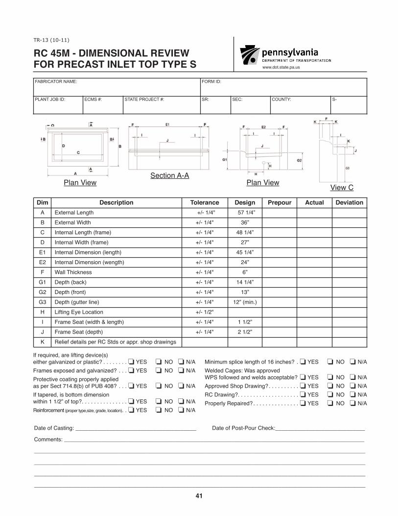
41
�������������� ��������� ��������������� ��������
�������������
BBB�0:?�>?-?1�;-�@>
����������� �� �� ���
������������ �� ���� ���������������� ��� ���� ������� ��
�-?1�:2��->?593��,,,,,,,,,,,,,,,,,,,,,,,,,,,,,,,,,,,,,,, �-?1�:2�$:>?�$:@=��41/6�,,,,,,,,,,,,,,,,,,,,,,,,,,,,,
�:8819?>��,,,,,,,,,,,,,,,,,,,,,,,,,,,,,,,,,,,,,,,,,,,,,,,,,,,,,,,,,,,,,,,,,,,,,,,,,,,,,,,,,,,,,,,,,,,,,,,,,
,,,,,,,,,,,,,,,,,,,,,,,,,,,,,,,,,,,,,,,,,,,,,,,,,,,,,,,,,,,,,,,,,,,,,,,,,,,,,,,,,,,,,,,,,,,,,,,,,,,,,,,,,,,
,,,,,,,,,,,,,,,,,,,,,,,,,,,,,,,,,,,,,,,,,,,,,,,,,,,,,,,,,,,,,,,,,,,,,,,,,,,,,,,,,,,,,,,,,,,,,,,,,,,,,,,,,,,
,,,,,,,,,,,,,,,,,,,,,,,,,,,,,,,,,,,,,,,,,,,,,,,,,,,,,,,,,,,,,,,,,,,,,,,,,,,,,,,,,,,,,,,,,,,,,,,,,,,,,,,,,,,
,,,,,,,,,,,,,,,,,,,,,,,,,,,,,,,,,,,,,,,,,,,,,,,,,,,,,,,,,,,,,,,,,,,,,,,,,,,,,,,,,,,,,,,,,,,,,,,,,,,,,,,,,,,
$7-9�)51B&1/?5:9����
��� �� ����!��� ��������� �� ��� �����"� ��!"�� ��#��!���� �C?1=9-7� 193?4 ������ �����F�� �C?1=9-7�*50?4 ������ �F� �9?1=9-7� 193?4��2=-81� ������ �����F�� �9?1=9-7�*50?4��2=-81� ������ ��F��� �9?1=9-7��5819>5:9��7193?4� ������ �����F��� �9?1=9-7��5819>5:9��B193?4� ������ ��F�� *-77�'45/691>> ������ �F��� �1;?4��.-/6� ������ �����F��� �1;?4��2=:9?� ������ � F�� �1;?4��3@??1=�7591� ������ ��F��859���� 52?593��D1� :/-?5:9 ������� �=-81�&1-?��B50?4���7193?4� ������ ����F�� �=-81�&1-?��01;?4� ������ ����F�� %17512�01?-57>�;1=�%��&?0>�:=�-;;=��>4:;�0=-B593>
)51B��
!5958@8�>;75/1�7193?4�:2����59/41>� ��� +�& ������ "# � "�*17010��-31>��*->�-;;=:A10�*$&�2:77:B10�-90�B170>�-//1;?-.71� � +�& ������ "# � "��;;=:A10�&4:;��=-B593� ��������������������� +�& ������ "# � "�%���=-B593������������������������������������������ +�& ������ "# � "�$=:;1=7D�%1;-5=10� ������������������������������� +�& ������ "# � "�
�2�=1<@5=10��-=1�752?593�01A5/1�>�15?41=�3-7A-95E10�:=�;7->?5/� ����������������� +�& ������ "# � "��=-81>�1C;:>10�-90�3-7A-95E10� ������� +�& ������ "# � "�$=:?1/?5A1�/:-?593�;=:;1=7D�-;;7510�->�;1=�&1/?�������.��:2�$(����� ������� +�& ������ "# � "���2�?-;1=10��5>�.:??:8�05819>5:9�B5?459�����F�:2�?:;�������������������������������� +�& ������ "# � "�%1592:=/1819? �;=:;1=�?D;1�>5E1��3=-01��7:/-?5:9������ +�& ������ "# � "�
$7-9�)51B

42
������������������������������������ �������������������������
�����������
666�%/3�23#3&�0#�42
����������� �� �� ��� ���������������������������������������������������������������������
������������ �� ���� ���������������� ��� ���� ������� ��
!# �(�'!&)!%$ �%"�'�$�� �(! $ �'�&%*' ��)*�" �+!�)!%$� �&.(3) �������� *%3) �������� �.3&1.#,��*-&.2*/. �������� #,,��)*$+.&22 �������� �/,&��/$#3*/. ������
� �&*()3���#7��5#1*#3*/.�'1/-�/.&2*%&�3/�3)&�/3)&1 ����� ������
� �&03)�/'��.(,& �������
�1#-&��./$+/432��2��.%*$#3&% ��������������������������� !�� ���� �����,&$31*$#,�(1/4.%�0&1�%1#6*.( �������������������������������!�� ���� �����&*.'/1$&-&.3��2*9&��(1#%&��,/$#3*/.� �������������������!�� ���� ����
�001/5&%��)/0��1#6*.( ���������������������������������������!�� ���� ����������1#6*.( ���������������������������������������������������������!�� ���� �����&0#*1&%��1/0&1,8 �������������������������������������������������!�� ���� ����
�#3&�/'��#23*.( �""""""""""""""""""""""""""""""""""""""" �#3&�/'��/23��/41��)&$+ """""""""""""""""""""""""""""
�/--&.32 �"""""""""""""""""""""""""""""""""""""""""""""""""""""""""""""""""""""""""""""""""""""""""""""""""
"""""""""""""""""""""""""""""""""""""""""""""""""""""""""""""""""""""""""""""""""""""""""""""""""""""""""""
"

43
TR-15 (3-12)
www.dot.state.pa.us
FABRICATOR NAME: FORM ID:
PLANT JOB ID: ECMS #: STATE PROJECT #: SR: SEC: COUNTY: S-
Date of Casting: _______________________________________ Date of Post-Pour Check:_____________________________
Comments: _________________________________________________________________________________________________
___________________________________________________________________________________________________________
___________________________________________________________________________________________________________
___________________________________________________________________________________________________________
___________________________________________________________________________________________________________
___________________________________________________________________________________________________________
Plan View Section A-A
Dim Description Tolerance Design Prepour Actual DeviationA Length +/- 3/8"B Width +/- 3/8"C Internal Dimension +/- 1/4"D Wall Thickness +/- 1/4"E Hole Location +/- 1/2"F Height (Max. variation from one side to the other: 1/4") +/- 1/2"G Depth of Angle +/- 1/8"H Lid Thickness +/- 1/4"K Relief Details per approved shop drawing
L Location of hole drain +/- 1/2"
Frame Knockouts as Indicated . . . . . . . . . . . . . . . . . . . . . . . . . . . . . . . . . . . . . . . . . . . . . . . . . . . . . . . . . . . o YES o NO o N/AElectrical Ground Per Drawing . . . . . . . . . . . . . . . . . . . . . . . . . . . . . . . . . . . . . . . . . . . . . . . . . . . . . . . . . . . o YES o NO o N/AReinforcement (size, grade, location) . . . . . . . . . . . . . . . . . . . . . . . . . . . . . . . . . . . . . . . . . . . . . . . . . . . . . . o YES o NO o N/A Approved Shop Drawing . . . . . . . . . . . . . . . . . . . . . . . . . . . . . . . . . . . . . . . . . . . . . . . . . . . . . . . . . . . . . . . . o YES o NO o N/A RC Drawing . . . . . . . . . . . . . . . . . . . . . . . . . . . . . . . . . . . . . . . . . . . . . . . . . . . . . . . . . . . . . . . . . . . . . . . . . . o YES o NO o N/AProperly Repaired . . . . . . . . . . . . . . . . . . . . . . . . . . . . . . . . . . . . . . . . . . . . . . . . . . . . . . . . . . . . . . . . . . . . . o YES o NO o N/A
RC-82M - DIMENSIONAL REVIEW FOR PRECASTHEAVY DUTY JUNCTION BOX JB11/JB12

44
DIMENSIONAL REVIEW FOR PRECAST“D” ENDWALL
TR-16 (8-11)
www.dot.state.pa.us
FABRICATOR NAME: FORM ID: TYPE #:
PLANT JOB ID: ECMS #: STATE PROJECT #: SR: SEC: COUNTY: S-
Dim Description Tolerance Design Prepour Actual DeviationA Length of wall <36" = +/- 1/4" >36" = +/- 3/8"B Base Flange Width +/- 1/4"C Wall Thickness +/- 1/4"
D Base Thickness (Levelness ofBottom to be within 1/2") +/- 1/4"
E Hole Size at discretion of manufacture
F
Location of Openings Variation from one edge to another (of Centerline from one to another)
+/- 2" +/- 3/4"
G Wall Height <36" = +/- 1/4" >36" = +/- 3/8"
HOverall HeightVariation from one edge to the other
<36" = +/- 1/4" >36" = +/- 3/8"
Block out between 2” and 4” > pipe O.D: . . . . . .o YES o NOReinforcement (size, grade, location) . . . . . . . .o YES o NOApproved Shop Drawing . . . . . . . . . . . . . . . . . .o YES o NO
RC - Drawing . . . . . . . . . . . . . . . . . . . . . . . . . . .o YES o NORepaired Properly . . . . . . . . . . . . . . . . . . . . . . .o YES o NO
Date of Casting: _______________________________________ Date of Post-Pour Check:_____________________________
Comments: _________________________________________________________________________________________________
___________________________________________________________________________________________________________
___________________________________________________________________________________________________________
___________________________________________________________________________________________________________

45
TR-17 (3-12)
www.dot.state.pa.us
FABRICATOR NAME: FORM ID:
PLANT JOB ID: ECMS #: STATE PROJECT #: SR: SEC: COUNTY: S-
Date of Casting: _______________________________________ Date of Post-Pour Check:_____________________________
Comments: _________________________________________________________________________________________________
___________________________________________________________________________________________________________
___________________________________________________________________________________________________________
___________________________________________________________________________________________________________
Plan View View A-A
Dim Description Tolerance Design Prepour Actual Deviation
A Length of Low Wall < 36” =+/- 1/4” 36” = +/- 3/8”
A Length of High Wall < 36” =+/- 1/4” 36” = +/- 3/8”
B Base Flange Width +/- 1/4”C Wall Thickness +/- 1/4”D Base Thickness (Levelness of Bottom to be within 1/2”) +/- 1/4”E Hole Size at discretion of manufacturer
F Location of Openings - Variation from one edgeto another (of Centerline from one to another)
+/- 2”+/- 3/4”
G Wall Height < 36” =+/- 1/4” 36” = +/- 3/8”
H Overall HeightVariation from one edge to the other
< 36” =+/- 1/4” 36” = +/- 3/8”
Block between 2” and 4” > pipe O.D. . . . . . . . . . . . . . . . . . . . . . . . . . . . . . . . . . . . . . . . . . . . . . . . . . . . . . . o YES o NO o N/AReinforcement (size, grade, location) . . . . . . . . . . . . . . . . . . . . . . . . . . . . . . . . . . . . . . . . . . . . . . . . . . . . . . o YES o NO o N/A Approved Shop Drawing . . . . . . . . . . . . . . . . . . . . . . . . . . . . . . . . . . . . . . . . . . . . . . . . . . . . . . . . . . . . . . . . o YES o NO o N/A RC Drawing . . . . . . . . . . . . . . . . . . . . . . . . . . . . . . . . . . . . . . . . . . . . . . . . . . . . . . . . . . . . . . . . . . . . . . . . . . o YES o NO o N/AProperly Repaired . . . . . . . . . . . . . . . . . . . . . . . . . . . . . . . . . . . . . . . . . . . . . . . . . . . . . . . . . . . . . . . . . . . . . o YES o NO o N/A
DIMENSIONAL REVIEW FOR PRECAST D-E ENDWALL

46
DIMENSIONAL REVIEW FOR PRECASTDW ENDWALL
TR-18 (3-12)
www.dot.state.pa.us
FABRICATOR NAME: FORM ID: TYPE #:
PLANT JOB ID: ECMS #: STATE PROJECT #: SR: SEC: COUNTY: S-
Dim Description Tolerance Design Prepour Actual DeviationA Length of Back Wall < 36" =+/- 1/4" 36" = +/- 3/8"B Base Flange Width +/- 1/4"C Wall Thickness +/- 1/4"
D Base Thickness (Levelness ofBottom to be within 1/2") +/- 1/4"
EWing Wall LengthVariation in length from one wallto the other: 1/2"
< 36" =+/- 1/4" 36" = +/- 3/8"
F Dimension between Wing Walls < 36" =+/- 1/4" 36" = +/- 3/8"
GTop of Wing Wall to top of BackWall Variation, (Right wall to Left wall)
+/- 1/2" +/- 1/4"
H Face of Wing Wall Height +/- 1/4"I Overall Height +/- 3/8"
J Hole sizes at discretion of manufacturer
K
Location of OpeningsVariation from one edge to another (of Center-Line from oneto the other) max. 3/4"
+/- 2"
Block out between 2” and 4” > pipe O.D: . . . . . .o YES o NOReinforcement (size, grade, location) . . . . . . . .o YES o NOApproved Shop Drawing . . . . . . . . . . . . . . . . . .o YES o NO
RC - Drawing . . . . . . . . . . . . . . . . . . . . . . . . . . .o YES o NORepaired Properly . . . . . . . . . . . . . . . . . . . . . . .o YES o NO
Date of Casting: _______________________________________ Date of Post-Pour Check:_____________________________
Comments: _________________________________________________________________________________________________
___________________________________________________________________________________________________________
___________________________________________________________________________________________________________
___________________________________________________________________________________________________________

47
�������������
999�(26�56%6)�3%�75
����������� �� �� ���
������������ �� ���� ���������������� ��� ���� ������� ��
�%6)�2*��%56-1+��$$$$$$$$$$$$$$$$$$$$$$$$$$$$$$$$$$$$$$$ �%6)�2*��256��274��,)'.�$$$$$$$$$$$$$$$$$$$$$$$$$$$$$
�200)165��$$$$$$$$$$$$$$$$$$$$$$$$$$$$$$$$$$$$$$$$$$$$$$$$$$$$$$$$$$$$$$$$$$$$$$$$$$$$$$$$$$$$$$$$$$$$$$$$$
$$$$$$$$$$$$$$$$$$$$$$$$$$$$$$$$$$$$$$$$$$$$$$$$$$$$$$$$$$$$$$$$$$$$$$$$$$$$$$$$$$$$$$$$$$$$$$$$$$$$$$$$$$$
$$$$$$$$$$$$$$$$$$$$$$$$$$$$$$$$$$$$$$$$$$$$$$$$$$$$$$$$$$$$$$$$$$$$$$$$$$$$$$$$$$$$$$$$$$$$$$$$$$$$$$$$$$$
$$$$$$$$$$$$$$$$$$$$$$$$$$$$$$$$$$$$$$$$$$$$$$$$$$$$$$$$$$$$$$$$$$$$$$$$$$$$$$$$$$$$$$$$$$$$$$$$$$$$$$$$$$$
$$$$$$$$$$$$$$$$$$$$$$$$$$$$$$$$$$$$$$$$$$$$$$$$$$$$$$$$$$$$$$$$$$$$$$$$$$$$$$$$$$$$$$$$$$$$$$$$$$$$$$$$$$$
$$$$$$$$$$$$$$$$$$$$$$$$$$$$$$$$$$$$$$$$$$$$$$$$$$$$$$$$$$$$$$$$$$$$$$$$$$$$$$$$$$$$$$$$$$$$$$$$$$$$$$$$$$$
�/%1�!-)9 !-)9����
��� ����������� ��������� ������ ������� ������ �� ������
� �)1+6,�2*��%',��)+ ���=���������=�<��=�������� =
� �%5)��/%1+)�"-(6, �������=� "%//� ,-'.1)55 �������=� �%5)� ,-'.1)55 ��)8)/1)55�2*��26620�62�&)�9-6,-1���=� �������=� �2/)��-;)5
� �2'%6-21�2*��3)1-1+5���!%4-%6-21�*420�21)�)(+)62�%126,)4��2*��)16)4/-1)�*420�21)�62�%126,)4�
����=������=
� "%//��)-+,6 �������=�
� �8)4%//��)-+,6 ���=���������=�<��=�������� =
�/2'.�&)69))1�=�%1(��=���3-3)����� ������������������������������������������������������������������������������������������������������������� #�� ������ �� � ����)-1*24')0)16��5-;)��+4%()��/2'%6-21� ������������������������������������������������������������������������������������������������������������� #�� ������ �� � �����33428)(��,23��4%9-1+ ��������������������������������������������������������������������������������������������������������������������������������� #�� ������ �� � ��������4%9-1+ ����������������������������������������������������������������������������������������������������������������������������������������������������� #�� ������ �� � ����423)4/:��)3%-4)( ������������������������������������������������������������������������������������������������������������������������������������������� #�� ������ �� � �����
��������� �������� �� ����������������

48
DIMENSIONAL REVIEW FOR PRECASTSUBSURFACE DRAIN OUTLET ENDWALL
TR-20 (3-12)
www.dot.state.pa.us
FABRICATOR NAME: FORM ID: TYPE #:
PLANT JOB ID: ECMS #: STATE PROJECT #: SR: SEC: COUNTY: S-
Dim Description Tolerance Design Prepour Actual DeviationA Length +/- 3/8"B Width +/- 1/4"C Depth +/- 1/4"D Void Location +/- 1/4"E Rebar Location +/- 1/4"
FRebar Extension from end ofDrain Deviation from one bar tothe other
+/- 1/2" +/- 1/4"
Protruding Bars Properly Coated: . . . . . . . . . . .o YES o NOReinforcement (size, grade, location) . . . . . . . .o YES o NOApproved Shop Drawing . . . . . . . . . . . . . . . . . .o YES o NO
RC - Drawing . . . . . . . . . . . . . . . . . . . . . . . . . . .o YES o NORepaired Properly . . . . . . . . . . . . . . . . . . . . . . .o YES o NO
Date of Casting: _______________________________________ Date of Post-Pour Check:_____________________________
Comments: _________________________________________________________________________________________________
___________________________________________________________________________________________________________
___________________________________________________________________________________________________________
___________________________________________________________________________________________________________

49
��������� �������� �� ������������ ��
������������
777�&04�34#4'�1#�53
����������� �� �� ��� ���������������������������������������������������������������������
������������ �� ���� ���������������� ��� ���� ������� ��
�2'%#34��05/&��#22+'2��034 �2'%#34��05/&��#22+'2��#/'-��� ����������� ��������� ������ ����� � ��� �� ��!���������0343� �'/)4* � ��1'2�<�+/�-'/)4*���� ;�.#8��� �'14* ����� �� +&4* ����� �� �-04��'+)*4��+/3+&'� ��� ���������� �-04��'+)*4��0543+&'�� ��� ��������� '$��*+%,/'33 ����� �� �-04��'14* ��������54�0(��-#4/'33
�'/)4*3�40���(''4 ���'/)4*3�06'2���(''4 �
����#/'-3� �'+)*4 ����� �� �'/)4* ����� �� �#/'-�'/&�40�-+(4+/)�*#2&7#2' ��9..'42+%#-�#/&����� ;�� �*+%,/'33���'/'2#-�� ����� �
�*+%,/'33��#4�054'2��;� �������� �02&'2� +&4* ����� ��54�0(��-#4/'33
�'/)4*3�40���(''4 ���'/)4*3�06'2���(''4 �
�2%*+4'%452#-�(+/+3*�'3��.''4�3#.1-'�1#/'-������������� !�� � ���'+/(02%'.'/4��3+:'��)2#&'��-0%#4+0/� ���������������������������� !�� � ���11206'&��*01��2#7+/) ������������������������������������������������ !�� � ��
�#4'�0(��#34+/)��""""""""""""""""""""""""""""""""""""""" �#4'�0(��034��052��*'%,�"""""""""""""""""""""""""""""�0..'/43��""""""""""""""""""""""""""""""""""""""""""""""""""""""""""""""""""""""""""""""""""""""""""""""""""""""""""""""""""""""""""""""""""""""""""""""""""""""""""""""""""""""""""""""""""""""""""""""""""""""""""""
������2#7+/) ������������������������������������� !�� � ���'1#+2'&��201'2-9������������������������������ !�� � ��

50
�������������
%%%���"�!"�"�����#!
����������� �� �� ���
������������ �� ���� ���������������� ��� ���� ������� ��
������"!������ ����$� !�������������������������������������������������������������������������������������������������������������
�����������������������������������������������������������������������������������������������������������
�����������������������������������������������������������������������������������������������������������
�����������������������������������������������������������������������������������������������������������
�����������������������������������������������������������������������������������������������������������
�����������������������������������������������������������������������������������������������������������
�����������������������������������������������������������������������������������������������������������
���"�������
�� ���������������������������������
���� �"��������&������������������������������������������������������������������������������������������������������������������������������������������� �� �#�� � ���� �����"������� ��� �&� ���� �� ������������������������������������������������������������������������������������������������������������������������������������������� ��� ������ � � ������#���"# ����"������������������������������������������ ��"�������!"���# ������������������������������������
�%� $�$& ���
����� ����� ���� �#�� �
��������������� ��
�$������ �������� ��#�!!$����� ��� ����� ��� � �#����� ��"%�#�� �%$�#����� ��"%�#��

51
DIMENSIONAL REVIEW FOR PRESTRESSED ADJACENT BOX BEAMS
TR-23 (8-11)
www.dot.state.pa.us
FABRICATOR NAME: FORM ID: TYPE #:
PLANT JOB ID: ECMS #: STATE PROJECT #: SR: SEC: COUNTY: S-
Reinforcement (size, grade, location) . . . . . . . .o YES o NOApproved Shop Drawing . . . . . . . . . . . . . . . . . .o YES o NO
RC - Drawing . . . . . . . . . . . . . . . . . . . . . . . . . . .o YES o NORepaired Properly . . . . . . . . . . . . . . . . . . . . . . .o YES o NO
Date of Casting: _______________________________________ Date of Post-Pour Check:_____________________________
Comments: _________________________________________________________________________________________________
___________________________________________________________________________________________________________
___________________________________________________________________________________________________________
___________________________________________________________________________________________________________
Dim Description Tolerance Design Prepour Actual DeviationA Length + 1/2", -1"B Width +/- 1/4"C Height +1/2", -1/4"D Vertical Chamber 1" or > +/- 50%, < 1" +/- 1/2"E Horizontal Chamber Up to 40': 1/4", 40' to 60': 3/8", > 60': 1/2"F Bearing Area Flatness +/- 1/8"G Insert Placement +/- 1/2"H Stirrup Projection +/- 1/4"J Dowell Holes +/- 1/2"K Tie Rod Holes +/- 1/2"
Out of Square +/- 1/2"Cracks or SpallMiscellaneousTop Slab (in) + 1/2", - 1/8"Sidewall Thickness (in) + 3/8", - 1/8"Location of Strand +/- 1/4"Debonding of StrandSkew of Beam End +/- 1/2"
Batter of Beam End +/- 3/8" <48” Beam Height+/- 5/8" >48” Beam Height
Safety Post LocationParapet Projections - 0", + 1"Horizontal Form Misalignment +/- 3/16"Positive Moment Steel Location
Bearing Area with Daps Tolerance Design Prepour Actual DeviationMarked End A +/- 1/8"Marked End B +/- 1/8"Marked End C +/- 1/8"Marked End D +/- 1/8"Unmarked End A +/- 1/8"Unmarked End B +/- 1/8"Unmarked End C +/- 1/8"Unmarked End D +/- 1/8"

52
%51/1�"->7���� ��"�!� #��� ����!���� ��"��� !� �$! ��#$�� ��%��#���� !1:3@4 ��� ������� +50@4 ������� �1534@ �� �������� *1>@5/-8��-9.1> ���;>���������������������� �� �;>5E;:@-8��-9.1> )<�@;��������������@;�����������
����� �� �1->5:3��>1-��8-@:1?? ������� �:?1>@�%8-/191:@ ���� �� '@5>>A<�%>;61/@5;: ������� �;C18��;81? ���� � (51�&;0��;81? ���� �
$A@�$2�'=A->1 ���� ��>-/7?�$>�'<-88?"5?/188-:1;A?(;<�'8-.��5:� ���� �'501C-88?�(45/7:1??��5:� ������������!;/-@5;:�;2�'@>-:0 �������1.;:05:3�;2�'@>-:0'71C�;2�.1-9�1:0 ���� ��-@@1>�;2�.1-9�1:0 ����������G��1-9��1534@
����������G��1-9��1534@'-21@D�%;?@�8;/-@5;:%->-<1@�<>;@1/@5;:?��' � ��������G�;>5E;:@-8�2;>9�95?�-853:91:@ �������%;?5@5B1�9;91:@�?@118�8;/-@5;:���!�����!���&�#����� " ����!���� ��"��� !� �$! ��#$�� ��%��#���"->710��:0�� ������"->710��:0�� ������"->710��:0�� ������"->710��:0�� ������):9->710��:0�� ������):9->710��:0�� ������):9->710��:0�� ������):9->710��:0�� ������
,1? #;&15:2;>/191:@��?5E1��3>-01��8;/-@5;:��
�-@1�;2��-?@5:3� �<<>;B10�'4;<��>-C5:3��-@1�;2�%;?@�%;A>��41/7� &��F��>-C5:3�
%>;<1>8D�&1<-5>10�
�������������������� ������������ �������������
�����������
CCC0;@?@-@1<-A?
����������� �� �� ��� ���������������������������������������������������������������������
������������ �� ���� ���������������� ��� ���� ������� ��
����!�"������!����%�!"�
��%���(��!

53
������������
???�-8<�;<*<.�9*�=;
��������������
� ���������� ������� ���������������� ��� ���� ������� ��
DAP DETAIL
ece Mark:
��!��.<*25
��������� �������� � ��� �����������
����������
��� ����������� ��������� ������ ����� � ��� �� ��!������� �.70<1 ����C���C�� '2-<1�$89��5*70. �����C����� C� '2-<1��8<<86��5*70. �����C����� C� '2-<1�'.+ �����C����� C� �.201<��.*6 ����C����� C� �.201<�$89��5*70. ����� C� �.201<��8<<86��5*70. ����� C� #?..9 ������C�9.:�/<� &.:<2,*5��1*6+.: B�C�����������C�������C
�.*:270��:.*��5*<7.;; ������C!5*<.��8,*<287 ������ C#<2::=9�!:83.,<287 ������ C#<2::=9��8*<270��87-2<287
� #<:*7-��8>.:�2;,.55*7.8=;�8,*<287�8/�#<:*7- ���� C�.+87-270�8/�#<:*7-#4.?�8/��.*6��7-�*<<.:�8/��.*6��7- �������C�� �C��.*6��.201<
�������C�� �C��.*6��.201<#*/.<@�!8;<��8,*<287�85-��8?7��8,*<287 ����C�8:2A87<*5��8:6��2;*52076.7< �������C�:*,4;�8:�#9*55;!8;2<2>.��8>.6.7<�#<..5��8,*<287
���������������������� ��������� ������ ����� � ��� �� ��!�������*:4.-��7-�� �����C�*:4.-��7-�� �����C�*:4.-��7-�� �����C�*:4.-��7-�� �����C%76*:4.-��7-�� �����C%76*:4.-��7-�� �����C%76*:4.-��7-�� �����C%76*:4.-��7-�� �����C
�*<.�8/��*;<270��))))))))))))))))))))))))))))))))))))))) �*<.�8/�!8;<�!8=:��1.,4�)))))))))))))))))))))))))))))�866.7<;�*7-�8:�'*2>.:;�)))))))))))))))))))))))))))))))))))))))))))))))))))))))))))))))))))))))))))))))))))))))))))))))))))))))))))))))))))))))))))))))))))))))))))))))))))))))))))))))))))))))))))))))))))))))))))))))))))))))))))))))))))))))))))))))))))))))))))))))))))))))))))))))))))))))))))))))))))))))))))))))))))))))))))))))))))))))))))))))))
".27/8:,.6.7<��;2A.��0:*-.��58,*<287� ������������������������������������������������������������������������������������������������������������� (�# ������ � � �����99:8>.-�#189��:*?270 ��������������������������������������������������������������������������������������������������������������������������������� (�# ������ � � ����"���:*?270 ����������������������������������������������������������������������������������������������������������������������������������������������������� (�# ������ � � ���!:89.:5@�".9*2:.- ������������������������������������������������������������������������������������������������������������������������������������������� (�# ������ � � �����

54
DIMENSIONAL REVIEW FOR PRECASTNEXT BEAM
TR-26 (8-11)
www.dot.state.pa.us
FABRICATOR NAME: FORM ID: TYPE #:
PLANT JOB ID: ECMS #: STATE PROJECT #: SR: SEC: COUNTY: S-
Dim Description Tolerance Design Prepour Actual DeviationA1 Depth Stem & Fillets +/- 1/4"A2 Depth Stem & Fillets +/- 1/4"B Thickness Top Flange + 1/4" - 1/8"C Depth Overall +/- 1/4"
D Width Flanges +/- 1/4"
E1 Width Stem +/- 1/8"
E2 Width Stem +/- 1/8"
F Length + 1/2", 1"
G Center to center of bearings +/- 1/2"
Centerline bearing to beam end +/- 3/4"
Stem perpendicularity 1/8" per vertical foot
Distance between stems +/- 1/4"
Exposed Beam Ends deviationfrom square/designated skew
horizontal ± 1/4"
vert ±1/8" per 1', max 1/2"
Deviations of ends (vert. batter) ± 3/8"
Debonding of strand Per Drawing
Inserts ± 1/2"
Bearing Area FlatnessMark end ± 1/16" 0" 0"
Non Mark end ± 1/16" 0" 0"
Stirrup bars (projection) ± 3/4"
Stirrup bars (longitudinal) <12" ±1/2", 12" +1"/ 2"
H Horizontal alignment (sweep) ± 1/8" Per 10 ft
Horizontal Form Misalignment ± 3/16"
Location of Strand ± 1/4"
Position post tensioning duct ± 1/4"
Longitudinal position of lifters ± 6"
J Camber differential (adjacent) 1/4" per 10', max 3/4" Show on framing plan
Positive Moment Steel Location ± 3/8"
Projection from end of beam ± 1/2"
Cracks or Spalls
TR-26 (continued next page)

55
Reinforcement (size, grade, location) . . . . . . . .o YES o NOApproved Shop Drawing . . . . . . . . . . . . . . . . . .o YES o NO
Chamfers ground and sealed . . . . . . . . . . . . . . .o YES o NORepaired Properly . . . . . . . . . . . . . . . . . . . . . . .o YES o NO
Date of Casting: _______________________________________ Date of Post-Pour Check:_____________________________
Comments: _________________________________________________________________________________________________
___________________________________________________________________________________________________________
___________________________________________________________________________________________________________
___________________________________________________________________________________________________________
Bearing Area with Daps Tolerance Design Prepour Actual DeviationMarked End Nearside A +/- 1/8"Marked End Nearside B +/- 1/8"Marked End Farside A +/- 1/8"Marked End Farside B +/- 1/8"
Unmarked End Nearside A +/- 1/8"
Unmarked End Nearside B +/- 1/8"
Unmarked End Farside A +/- 1/8"
Unmarked End Farside B +/- 1/8"
TR-26 (continued)

56
��������� �������� � ��� ��������������
�����������
>>>�+6;�:;(;,�7(�<:
����������� �� �� ��� ���������������������������������������������������������������������
������������ �� ���� ���������������� ��� ���� ������� ��
����������
������� ����� �����!���! ���� ���� ��!��� � ���# ��"#�� ��$��"����� �,7;/�D�$;,4����033,;: B������ �,7;/D$;,4����033,;: B����� %/0*25,::�D�%67��3(5., �������D����� �,7;/�D�!=,9(33 B����� '0+;/�D��3(5.,: B������ '0+;/�D�$;,4 B������ '0+;/�D�$;,4 B����� �,5.;/ �������D���� �,5;,9�;6�*,5;,9�6-�),(905.: B����
�,5;,9305,D),(905.�;6�),(4,5+ B� ��
$;,4�7,97,5+0*<3(90;@ ����7,9�=,9;0*(3�-66;�0:;(5*,�),;>,,5�:;,4: B����
�?76:,+��,(4��5+:�D�$8<(9,/690A65;(3�B����=,9;�B��������4(?
����5:,9;: B����
�,(905.��9,(��3(;5,::
�(92�,5+�����������B���� � ��
65D�(92�,5+����B���� � �
$;099<7�)(9:��7961,*;065� B� ��
$;099<7�)(9:��365.0;<+05(3� �����B�����C����D�����
� �690A65;(3�(30.54,5; B�����",9���-;�690A65;(3��694��0:(30.54,5; B� ����6*(;065�6-�$;9(5+ B����"6:0;065�D�76:;D;,5:06505.�+<*;�65.0;<+05(3�76:0;065�6-�30-;,9:
� �(4),9�+0--,9,5;0(3��(+1(*,5;� ���������4(?� ��"6:0;0=,��64,5;�$;,,3��6*(;065 B� ��"961,*;065�-964�,5+�6-�),(4 B�����9(*2:�69�$7(33:
TR-27 (continued on next page)

57
������� ����� ����� ���%�"�����! ���� ���� ��!��� � ���# ��"#�� ��$��"���
�(92,+��5+�� B�����(92,+��5+�� B�����(92,+��5+�� B�����(92,+��5+�� B����&54(92,+��5+�� B����&54(92,+��5+�� B����&54(92,+��5+�� B����&54(92,+��5+�� B����
��! ��(;,�6-��(:;05.� #,05-69*,4,5;��:0A,��.9(+,��36*(;065��
�(;,�6-�"6:;D"6<9��/,*2 �7796=,+�$/67��9(>05."967,93@�#,7(09,+� �/(4-,9:�.96<5+�(5+�:,(3,+
#,4(92:��5+69�'(0=,9:� "3<4)5,::�"9,�"6:;��
TR-27 (continued)

58
�����������
<<<�+59�89(9,�6(�:8
����������� �� �� ���
������������ �� ���� ���������������� ��� ���� ������� ��
�(9,�5-��(8904.��''''''''''''''''''''''''''''''''''''''' �(9,�5-�!589�!5:7��/,*1�'''''''''''''''''''''''''''''
�533,498��'''''''''''''''''''''''''''''''''''''''''''''''''''''''''''''''''''''''''''''''''''''''''''''''''
'''''''''''''''''''''''''''''''''''''''''''''''''''''''''''''''''''''''''''''''''''''''''''''''''''''''''''
'''''''''''''''''''''''''''''''''''''''''''''''''''''''''''''''''''''''''''''''''''''''''''''''''''''''''''
��� ������� ��� ��������� ������ �����!� �� !�� ��"�� ���� �,4.9/���"0./9�#0+,� ���$�5-��,4.9/���@��(=���� �,4.9/����0++2, ���$�5-��,4.9/���@��(=���� �,4.9/����,-9�#0+, ���$�5-��,4.9/���@��(=��� %0+9/��� :980+,�� %0+9/����480+, ������@��(=��� �,0./9��� :980+,�� �,0./9����480+, ������@��(=��� %(22�$/0*14,88 �59�2,88�9/(4�������� %(22�$/0*14,88 �59�2,88�9/(4������� $56�#2()$/0*14,88 �59�2,88�9/(4������� �(8,�#2()$/0*14,88 �59�2,88�9/(4������� �(:4*/ �� %,,6��52,8 ������ %,2+�!2(9,8� �48,798� !589�$,48054��:*9 �� �,4.9/�5-� 665809,�#:7-(*,8 ���$�5-��49,74(2�#6(4����@��(=��� �49,74(2��0(.54(2 ������@��(=��
��������� �������� ���������� �
!759,*90;,�*5(904.�6756,72>�(6620,+ ������������������������������������������������������������������������������������������������������������������&�# ������ � � ��",04-57*,3,49��80?,��.7(+,��25*(9054� ��������������������������������������������������������������������������������������������������������������&�# ������ � � ����6675;,+�#/56��7(<04. ����������������������������������������������������������������������������������������������������������������������������������&�# ������ � � ���"���7(<04. ������������������������������������������������������������������������������������������������������������������������������������������������������&�# ������ � � ��!756,72>�",6(07,+ ��������������������������������������������������������������������������������������������������������������������������������������������&�# ������ � � ����
�
�
�
� ����
� ��
��
�

59
DIMENSIONAL REVIEW FOR MSE WALL PANELS
TR-29 (8-11)
www.dot.state.pa.us
FABRICATOR NAME: FORM ID: TYPE #:
PLANT JOB ID: ECMS #: STATE PROJECT #: SR: SEC: COUNTY: S-
Dim Description Tolerance Design Prepour Actual DeviationA Thickness +/- 1/4"B Width +/- 1/4"C Height +/- 1/4"D Wing to Corner +/- 1/4"
Reinforcement (size, grade, location) . . . . . . . .o YES o NOTop Finish . . . . . . . . . . . . . . . . . . . . . . . . . . . . . .o YES o NOBottom Finish . . . . . . . . . . . . . . . . . . . . . . . . . . .o YES o NOSurface Texture . . . . . . . . . . . . . . . . . . . . . . . . .o YES o NOCracks / Spalls . . . . . . . . . . . . . . . . . . . . . . . . . .o YES o NOSquareness . . . . . . . . . . . . . . . . . . . . . . . . . . . .o YES o NOChamfers . . . . . . . . . . . . . . . . . . . . . . . . . . . . . .o YES o NOHoneycomb . . . . . . . . . . . . . . . . . . . . . . . . . . . .o YES o NO
Grout Leaks . . . . . . . . . . . . . . . . . . . . . . . . . . . .o YES o NOExposed Rebar . . . . . . . . . . . . . . . . . . . . . . . . .o YES o NOExposed Chairs . . . . . . . . . . . . . . . . . . . . . . . . .o YES o NOOpenings / Block-outs . . . . . . . . . . . . . . . . . . . .o YES o NO1/8'' alignment for clevis loop . . . . . . . . . . . . . . .o YES o NOApproved Shop Drawing . . . . . . . . . . . . . . . . . .o YES o NORC - Drawing . . . . . . . . . . . . . . . . . . . . . . . . . . .o YES o NORepaired Properly . . . . . . . . . . . . . . . . . . . . . . .o YES o NO
Date of Casting: _______________________________________ Date of Post-Pour Check:_____________________________
Comments: _________________________________________________________________________________________________
___________________________________________________________________________________________________________
___________________________________________________________________________________________________________
___________________________________________________________________________________________________________

60
��������� �������� �� ������� ��
�����������
777�%04�34#4&�1#�53
����������� �� �� ��� ���������������������������������������������������������������������
������������ �� ���� ���������������� ��� ���� ������� ��
����������������
��� ���������� ��������� ������ ����� � ��� �� ��!������� �6&2#--��&*()4 ;����� �0440.�"*%4) ;����� �/0$,054��0440.�"*%4) ;����� �/0$,054�!01�"*%4) ;����� �/0$,054��&14) ��<����<� !01�"*%4) ;����� !01��&/(4) ����1&2�=�0'�-&/(4)����<��#8��� �0440.��&/(4) ����1&2�=�0'�-&/(4)����<��#8��� �0$#4*0/�0'��*'4*/(��#2%7#2& �39..&42*$#-�#/%������<�� !7*34 ����1&2�=�0'�-&/(4)
��� ��204&$4*6&�$0#4*/(�1201&2-9�#11-*&%
�&*/'02$&.&/4��3*:&��(2#%&� �20+&$4*0/�!01��0$#4*0/
�20+&$4*0/��0440.��0$#4*0/ ��#8*.5.���������'4���-#2&� $2&&/ ��)&$,��02�47*34
�#4&��'��#34*/( �11206&%� )01��2#7*/(�#4&��'��034��052��)&$, ������2#7*/(�201&2-9��&1#*2&%
���������������
�&.#2,3

61
�������������
:::�(27�67%7)�3%�86
����������� �� �� ���
������������ �� ���� ���������������� ��� ���� ������� ��
�%7)�2*��%67-1+��$$$$$$$$$$$$$$$$$$$$$$$$$$$$$$$$$$$$$$$ �%7)�2*��267��285��,)'.�$$$$$$$$$$$$$$$$$$$$$$$$$$$$$�200)176��$$$$$$$$$$$$$$$$$$$$$$$$$$$$$$$$$$$$$$$$$$$$$$$$$$$$$$$$$$$$$$$$$$$$$$$$$$$$$$$$$$$$$$$$$$$$$$$$$$$$$$$$$$$$$$$$$$$$$$$$$$$$$$$$$$$$$$$$$$$$$$$$$$$$$$$$$$$$$$$$$$$$$$$$$$$$$$$$$$$$$$$$$$$$$$$$$$$$$$$$$$$$$$$$$$$$$$$$$$$$$$$$$$$$$$$$$$$$$$$$$$$$$$$$$$$$$$$$$$$$$$$$$$$$$$$$$$$$$$$$$$$$$$$$$$$$$$$$$$$$$$$$$$$$$$$
��� ����������� ��������� ������ ������� ������ ���������� �%')�"-(7,� ������ <� �%')��)-+,7 ������ <� �7)0��)-+,7 ������ <� �%')�"-(7,� ,-'.1)66 ����<�����<�� �%81',�"-(7, ������� ���72����&/2'.2876�� ;3�� ������� �,)%5��);��/2'.287�72��-0)16-21�� ;3�� ������� �7)0� ,-'.1)66�������������������������������������������� �������
� �%')��)53)1(-'8/%5�72��7)0��(-**)5)1')�&)7:))1(-%+21%/6�21�&27,�6-()6�*520�7,)�67)0� ������
� �9)5%//��)1+7,��1'/8(-1+��7)0 ��������)9-%7-21��520��48%5)��)%685)(�217,)��-%+21%/�2*�7,)��5217��%') �<
"))3��2'%7-21��",)1��)48-5)(� �������!)57-'%/��%')��/%1)���)%685)(�:-7,�675%-+,7)(+)%'5266�9)57-'%/�*%')�2*�81-7 �������
�5217��%')��48%5)���)%685)(�*520�'251)5�72�'251)52*�*5217�*%')� �������
���� ��������������������
�)-1*25')0)17�%6�3)5��)6-+1 ��������������������������������������������������������������������������������������������������������������������������#�� ������ �� � ����/)%5%1')�72��7)0��������������������������������������������������������������������������������������������������������������������������������������������#�� ������ �� � �����/)%5%1')�72��%') ��������������������������������������������������������������������������������������������������������������������������������������������#�� ������ �� � �����/)%5%1')�72��%81',����������������������������������������������������������������������������������������������������������������������������������������#�� ������ �� � ����33529)(��,23��5%:-1+ ����������������������������������������������������������������������������������������������������������������������������������#�� ������ �� � ����523)5/;��)3%-5)( ��������������������������������������������������������������������������������������������������������������������������������������������#�� ������ �� � �����

62
�����������
===�+5:�9:):,�6)�;9
����������� �� �� ���
������������ �� ���� ���������������� ��� ���� ������� ��
�):,�5-��)9:04.��((((((((((((((((((((((((((((((((((((((( �):,�5-� 59:� 5;8��/,*1�(((((((((((((((((((((((((((((
�533,4:9��(((((((((((((((((((((((((((((((((((((((((((((((((((((((((((((((((((((((((((((((((((((((((((((((((
(((((((((((((((((((((((((((((((((((((((((((((((((((((((((((((((((((((((((((((((((((((((((((((((((((((((((((
(((((((((((((((((((((((((((((((((((((((((((((((((((((((((((((((((((((((((((((((((((((((((((((((((((((((((((
��� ������� ��� ��������� ������ ����!� �� !�� ��"�� ���� �<,8)22��,4.:/� ������@� �<,8)22�&0+:/ ������@ @����@� �25*1��,0./: ������@ @����@� �54.0:;+04)2�$54.;,�&0+:/ ����@ @� �54.0:;+04)2�$54.;,��09:)4*, ������@ �����@� $54.;,��,0./: ����@ @� �54.0:;+04)2��855<,�&0+:/ ����@�� @� �54.0:;+04)2��855<,��09:)4*, ������@ ����@� �54.0:;+04)2��855<,��,0./: ������@ @� �54.0:;+04)2�$54.;,��,4.:/ ������@� $8)49<,89,�$54.;,�&0+:/ ����@ @� �,-:�$8)49<,89,�$54.;,��09:)4*, ������@� "0./:�$8)49<,89,�$54.;,��09:)4*, ������@� $8)49<,89,��855<,�&0+:/ ����@ @� �,-:�$8)49<,89,��855<,��09:)4*, ������@ "0./:�$8)49<,89,��855<,��09:)4*, ������@! )8:0)2�$54.;,��,4.:/ ������@" �,<0):054��853�#7;)8,��254.��)9,��0).54)2 ������@ �@
�����������������������������������
�)8104.9� 856,82>��6620,+������������������������������������������������������������������������������������������������������������������������������� '�# ������ �� � ����8*/0:,*:;8)2��855<,9� 856,82>�#0?,+�)4+�#6)*,+ ����������������������������������������������������������������������������������������� '�# ������ �� � ���� 856,8��54*8,:,��5258��6620,+ ����������������������������������������������������������������������������������������������������������������������� '�# ������ �� � ����",04-58*,3,4:��90?,��.8)+,��25*):054� ������������������������������������������������������������������������������������������������������������� '�# ������ �� � ����6685<,+�#/56��8)=04. ��������������������������������������������������������������������������������������������������������������������������������� '�# ������ �� � ���� 856,82>�",6)08,+ ������������������������������������������������������������������������������������������������������������������������������������������� '�# ������ �� � ����������
�������� ��� #:)4+)8+�%40:� �5604.�%40:� "0./:��584,8��5604.�%40:� �,-:��584,8��5604.�%40:� �)2-�%40:� �)2-�%40:��5604.�%40:
�������� ��� $0,��)*1�%40:� "0./:��584,8�%40:� �,-:��584,8�%40:

63
�������������
999�&16�56#6'�2#�75
���������������������������
�������� �100'%6+10��1/210'065
�16�61��%#.'
�������� �'&&+0)��4176��+564+$76+10
�������� �100'%6+10��1/210'065
�16�61��%#.'
�������� �'&&+0)��4176��+564+$76+10
TR-33 (continued next page)

64
��� ����������� �������� ������ ������ ������ ��������� +&6*� ���<
� �'0)6* ���<
�.#$��+#)10#.5���37#4'����� ���<
�14/��'26*���.#$��*+%-0'55� ���<
�� �+(6+0)��05'46��7/$'4���������
� �+(6+0)��05'46��7/$'4���������
�� �19'.�14��'&&+0)��4176��1465 ���<��
�� �19'.�14��'&&+0)��4176��1465 ���<
�� �4176��*#00'.5
�� �4176��*#00'.5
� �4176��*#00'.5
� �4176��*#00'.5
�� �#5-'6��#6'4+#.��1%#6+10
�� �#5-'6��#6'4+#.��1%#6+10
� �#5-'6��#6'4+#.��1%#6+10
�';9#;��1%#6+10����
�';9#;��1%#6+10����
�';9#;��+/'05+10����
�';9#;��+/'05+10����
�106���.165��1%#6+10����
�106���.165��1%#6+10����
�106���.165��2#%+0)�����106���.165��2#%+0)����
�106���.165��+/'05+10����
�106���.165��+/'05+10����
�19'.��/$'&/'06��'8'.���� ���<
�����100'%6+10��19'.��41,'%6+10
�����100'%6+10��146��'%'55
�100'%6+10��;2' ��������������������������������������������� ��� ������� ����<:�<��*#/('4�#.10)�#..�$1661/�'&)'5 ����������� !�� ������ �� �1//'065 """""""""""""""""""""""""""""""""""""""""""""�<:�<��*#/('4�#.10)�#..�&19'.�5.165 ��������������� !�� ������ �� �1//'065 """""""""""""""""""""""""""""""""""""""""""""�.#0-�'&)'5�2'4�&4#9+0)�&'6#+. ����������������������� !�� ������ �� �1//'065 """""""""""""""""""""""""""""""""""""""""""""�'+0(14%'/'06��12��.'#4#0%'���=<����������������� !�� ������ �� �1//'065 """""""""""""""""""""""""""""""""""""""""""""�'+0(14%'/'06��1661/��.'#4#0%'��< ��������������� !�� ������ �� �1//'065 """""""""""""""""""""""""""""""""""""""""""""�'+0(14%'/'06��1661/��.'#4#0%'�< ��������������� !�� ������ �� �1//'065 """""""""""""""""""""""""""""""""""""""""""""
TR-33 (continued)

65
INVERSET DIMENSIONAL REVIEW SHEET
TR-34 (8-11)
www.dot.state.pa.us
FABRICATOR NAME: FORM ID: TYPE #:
PLANT JOB ID: ECMS #: STATE PROJECT #: SR: SEC: COUNTY: S-
Dim Description Tolerance Design Prepour Actual Deviation
L1 Deck overall length (along the East side) +/- ½”
L2 Deck overall length (along the West side) +/- ½”
C/C Center to center of bearings +/- ½”W Deck Top Width +/- ¼”
H1 Overall Height (North End Backwall-East) +/- ¼”
H2 Overall Height (North End Backwall-West) +/- ¼”
H3 Overall Height (South End Backwall-East) +/- ¼”
H4 Overall Height (South End Backwall-West) +/- ¼”
TR-34 (continued on next page)

66
Joint (size, location) . . . . . . . . . . . . . . . . . . . . . .o YES o NOHaunches (size, location) . . . . . . . . . . . . . . . . . .o YES o NOLift Holes (size, location ) . . . . . . . . . . . . . . . . . .o YES o NOBackwalls steel plates (size, location ) . . . . . . . .o YES o NOInserts, Studs (type, size, location) . . . . . . . . . .o YES o NO
Protective coating properly applied . . . . . . . . . .o YES o NOReinforcement (size, grade, location) . . . . . . . .o YES o NOApproved Shop Drawing . . . . . . . . . . . . . . . . . .o YES o NOChamfers ground and sealed . . . . . . . . . . . . . . .o YES o NORepaired Properly . . . . . . . . . . . . . . . . . . . . . . .o YES o NO
Date of Casting: _______________________________________ Date of Post-Pour Check:_____________________________
Comments: _________________________________________________________________________________________________
___________________________________________________________________________________________________________
___________________________________________________________________________________________________________
___________________________________________________________________________________________________________
Dim Description Tolerance Design Prepour Actual Deviation
A1 Distance between I-Beams (North End)
A2 Distance between I-Beams(South End)Deck Diagonals +/- ½”
T1 Deck Thickness (average on East side) +/- ¼”
T2 Deck Thickness (average on West side) +/- ¼”
DeltaHorizontal Sweep (measuredfrom concrete decking centerline) +/- ¼”
C1E Vertical Camber ( midspan at East side) +1/4” -3/8”
C1W Vertical Camber ( midspan at West side) +1/4” -3/8”
I-Beam Camber (East side , pre-load)I-Beam Camber (West side, pre-load)Flange tilting (East side beam, pre-load)Flange tilting (West side beam, pre-load)
S Deck Slope (at Unit s midspan) +/- ½ %P Parapet Height +/- ¼”K Parapet Width +/- ¼”F1 North Backwall Thickness +/- ¼”F2 South Backwall Thickness +/- ¼”
North Backwall End - Batter +/- ½”North Backwall End – Planar Surface +/- ¼”
Proper Angle to Deck (West side) +/- ¼”South Backwall End - Batter +/- ½”South Backwall End - Planar Surface +/- ¼”
Proper Angle to Deck (East side) +/- ¼”
TR-34 (continued)

67
DIMENSIONAL REVIEW FOR CON/SPANARCH STRUCTURE
TR-35 (8-11)
www.dot.state.pa.us
FABRICATOR NAME: FORM ID: TYPE #:
PLANT JOB ID: ECMS #: STATE PROJECT #: SR: SEC: COUNTY: S-
Dim Description Tolerance Design Prepour Actual DeviationA Span +/- 1/2"B Rise +/- 1/2"C Square (Plan) +/- 1/2"D Wall Thickness +/- 1/4"E Slab Thickness +/- 1/4"F Unit Lay Length (Max.) +/- 1/2"F Unit Lay Length (Min.) +/- 1/2"G Square Elevation +/- 1/2"H Leg Length +/- 1/2"I Leg Length +/- 1/2"
Date of Casting: _______________________________________ Date of Post-Pour Check:_____________________________
Comments: _________________________________________________________________________________________________
___________________________________________________________________________________________________________
___________________________________________________________________________________________________________
___________________________________________________________________________________________________________
Markings properly applied?. . . . . . . . . . o YES o NO oN/ASheathing duct diameters as specified on drawings? . . . . . . . . . . . . . o YES o NO oN/ASheathing ducts located within specified tolerances (¼” unless otherwise specified), both ends? . . . . . o YES o NO oN/APost-tensioning recess as specified on drawings? . . . . . . . . . . . . . o YES o NO oN/A Coatings properly applied? . . . . . . . . . . o YES o NO oN/A
Do special items (block outs, access openings, skews, etc.) comply with drawings? . . . . . . . . . . . . . o YES o NO oN/AReinforcement (size, grade, location): . o YES o NO oN/AWingwalls in accordance with approved shop drawings?. . . . . . . . . . . o YES o NO oN/AWingwall anchors in accordance with approved shop drawings?. . . . . . . . . . . o YES o NO oN/AApproved Shop Drawing. . . . . . . . . . . . o YES o NO oN/ARC - Drawing . . . . . . . . . . . . . . . . . . . . o YES o NO oN/ARepaired Properly. . . . . . . . . . . . . . . . . o YES o NO oN/A

68
PART 4 APPENDICES
Repair Procedures for Precast Concrete Products
Precast concrete is a manufactured material using natural ingredients that can be produced inalmost any combination of color, form or texture. Through exercising proper quality control,precast concrete manufacturing defects will be minimized; however, repairs to some extent areto be expected. Properly repaired precast concrete can be sound, durable and closely matchthe adjacent un-repaired concrete section.
The Department, in cooperation with the Pennsylvania Precast Concrete Association, hasdeveloped ‘preapproved’ repair procedures for precast concrete. For defects meeting theguidelines and limits given below, the Department will accept properly repaired precast concreteproducts.
Recurring defects must be evaluated to ensure that future repairs are reduced or eliminated:
Any repairs beyond the scope of this procedure may be submitted to the Structural MaterialsEngineer for evaluation on a case by case basis. Such repair proposals should include aphotograph or sketch of the affected area and a detailed repair proposal. Submitted repairs
must be presented to the Department’s plant inspector for verification (by initials).
����� �� !����������������
��� �����
��������������� ����������� ������ �
����
��
�����#������!�����
����#������!����� ����#�����
�!������#������!�����
����� �� !����������������
��� �����
��"�� ������������������
��� �������"�� ������������������
��� �����
��"�� ������������������
��� �����
� �!� !�������� � ���� ������� �
��"�� ������������������
��� �����
��
��
����

69
Definitions:
Defects:
Structural DefectBroken Corners, large spalls, reinforcement may be exposed. Depth range: greater than 2 to 6inch. Surface area less than 150in².
Cosmetic DefectChips and/or surface defects and fractures and spalls that do not expose reinforcement.Depth range up to 2 inch. Surface area less than 100 in². Very small surface voids caused byentrapped air voids at formed surfaces (bug holes) are normally considered a cosmetic defectthat does not require repair. Bug holes over 1/2 inch in diameter or clusters of bug holescovering an area larger than 100 in² are required to be repaired.
Surfaces:
Exposed SurfaceAny surface above normal water or grade level when applicable, and/or a surface that is notconcealed by other construction. An internal surface of a precast product is not considered anexposed surface.
Non-Exposed SurfaceAny surface below normal water or grade level when applicable, and/or a surface that will beconcealed by other construction. An internal surface of a precast product is considered a non-exposed surface.
Surface Finish
Architectural FinishAn architectural finish represents a finish with a specified standard of uniform appearance,surface details, color and texture. Approved samples shall establish the range of acceptabilitywith respect to color and texture variations, surface defects and overall appearance. Suchsamples shall be viewed at a distance consistent with the normal viewing distance of thestructure, but not less than 30 feet.
Conventional FinishPrecast concrete surfaces may have slight irregularities that are the result of form conditionsand form joints. These irregularities may include fins or protrusions less than 3/16 inch, orsurface voids as described above. These defects typically do not require repairs.
Special FinishA special finish is selected for specific projects and is to be specified as such on a projectby project basis. Such a finish consists of a specified application on the exposed and/or non-exposed surfaces of a precast product. These applications can include, but are not limited to,
epoxy coatings, bituminous coatings and requirements for patching extremely small holes.

70
Repair Procedures
Section 1 – For Structural Repairs of Exposed Surfaces with Conventional Finishes.− Areas to be repaired must be clean, sound and free of contaminants.− Make a 3/4 inch deep vertical surface along the perimeter of the damaged area.− Remove concrete for a minimum of 1inch behind all exposed reinforcement where
at least 2 inch of continually exposed reinforcement is visible.− Provide an aggregate fractured surface with a minimum surface profile of – 1/8 inch− Drill and insert 3/8 inch diameter steel expansion anchor pins on 4 inch centers for
damaged areas with depths greater than 3 inch when rebar is not prevalent. − Clean the repair surface.− If using a Bulletin 15 repair material, apply an approved bonding agent unless the
manufacturer’s instructions expressly state that a bonding agent is not required. If usingthe approved mix design, first apply a mortar scrub coat to the repair area, filling all voids.
− Fill the area with either a thoroughly mixed Bulletin 15 repair material in accordance with the Manufacturer’s recommendations, or with the approved concrete mix design.
− Cure the repaired area either in accordance with the Bulletin 15 manufacturer’s recommendations, or, in accordance with the approved quality control plan for a minimum of 24 hours.
− Evaluate the repaired area by applying a moderate blow with a 16 ounce hammer at several locations within the repaired area.
− The repaired area should closely match both the color and texture of the undamaged adjacent concrete surfaces.
Section 2 – For Structural Repairs of Non-Exposed Surfaces with Conventional Finishes.− Areas to be repaired must be clean, sound and free of contaminants.− Make a 3/4 inch deep vertical surface along the perimeter of the damaged area, where
applicable (where patch will feather to nothing.)− Remove concrete for a minimum of 1 inch behind all exposed reinforcement where
at least 2 inch of continually exposed reinforcement is visible.− Provide an aggregate fractured surface with a minimum surface profile of – 1/8 inch.− Drill and insert 3/8 inch diameter steel expansion anchor pins on 4 inch centers for
damaged areas with depths greater than 3 inch when rebar is not prevalent.− Clean the repair surface− If using a Bulletin 15 repair material, apply an approved bonding agent unless the
manufacturer’s instructions expressly state that a bonding agent is not required. If usingthe approved mix design, first apply a mortar scrub coat to the repair area, filling all voids.
− Fill the area with either a thoroughly mixed Bulletin 15 repair material in accordance with the manufacturer’s recommendations, or with the approved concrete mix design.
− Cure the repaired area either in accordance with the Bulletin 15 manufacturer’s recommendations, or, in accordance with the approved quality control plan for a minimum of 24 hours.
− Evaluate the repaired area by applying a moderate blow with a 16 ounce hammer at several locations of the repaired area.

71
Section 3 – For Cosmetic Repairs of Exposed Surfaces with Conventional Finishes
− Areas to be repaired must be clean, sound and free of contaminants.− If the depth exceeds 1 inch make a 3/4 inch deep vertical surface along the perimeter
of the -damaged area.− Provide an aggregate fractured surface with a minimum surface profile of – 1/8 inch.− Saturate the repair surface with clean water to provide a SSD condition when
applicable.− Fill the area with either a thoroughly mixed Bulletin 15 repair material in accordance
with the manufacturer’s recommendations, the approved concrete mix design, or if less than 1 inch in depth, a mortar mix.
− Cure the repaired area either in accordance with the Bulletin 15 manufacturer’s recommendations, or, in accordance with the approved quality control plan for the approved mix design for a minimum of 24 hours.
− If the depth exceeds 1 inch evaluate the repaired area by applying a moderate blow with a 16 ounce hammer at several locations of the repaired area.
− The repaired area should closely match both the color and texture of the undamaged adjacent concrete surfaces.
Section 4 – For Cosmetic Repairs of Non-Exposed Surfaces with Conventional Finishes
− Areas to be repaired must be clean, sound and free of contaminants.− If the depth exceeds 1 inch make a 3/4 inch deep vertical surface along the perimeter
of the damaged area.− Provide an aggregate fractured surface with a minimum surface profile of - 1/8 inch.− Saturate the repair surface with clean water to provide a SSD condition when
applicable.− Fill the area with either a thoroughly mixed Bulletin 15 repair material in accordance
with the manufacturer’s recommendations, the approved concrete mix design, or if less than 1 inch in depth, a mortar mix.
− If the depth exceeds 1 inch evaluate the repaired area by applying a moderate blow with a 16 ounce hammer at several locations of the repaired
Section 5 – For Structural Repairs of Exposed Surfaces with Architectural Finishes
− Areas to be repaired must be clean, sound and free of contaminants.− Make a 3/4 inch deep vertical surface along the perimeter of the damaged area, where
applicable.− Remove concrete for a minimum of 1 inch behind all exposed reinforcement where at
least 2 inches of continually exposed reinforcement is visible.− Provide an aggregate fractured surface with a minimum surface profile of – 1/8 inch− Drill and insert 3/8 inch diameter steel expansion anchor pins on 4 inch centers for
damaged areas with depths greater than 3 inch when rebar is not prevalent.− Clean the repair surface− If using a Bulletin 15 repair material, apply an approved bonding agent unless the
manufacturer’s instructions expressly state that a bonding agent is not required. If using the approved mix design, first apply a mortar scrub coat to the repair area, filling all voids.
− Fill the area with either a thoroughly mixed Bulletin 15 repair material in accordance with the manufacturer’s recommendations, or, in accordance with the approved quality control plan for a minimum of 24 hours.

72
− Cure the repaired area either in accordance with the Bulletin 15 manufacturer’s recommendations, or, in accordance with the approved Quality Control plan for a minimum of 24 hours.
− Evaluate the repaired area by applying moderate blow with a 16 ounce hammer at several locations of the repaired area.
− Apply a finish coat to the repaired area to match the approved architectural finish.
Note: A repair mix is typically developed through a trial and error process in order to match color and texture of the concrete surface. Slight variations can be expected due to the difference in age and curing conditions for the repair.
Section 6 – For Cosmetic Repairs of Exposed Surfaces with Architectural Finishes.
− Areas to be repaired must be clean, sound and free of contaminants.− If the depth exceeds 1 inch make a 3/4 inch deep vertical surface along the perimeter
of the damaged area, where applicable (where patch will feather to nothing.)− Provide an aggregate fractured surface with a minimum surface profile of – 1/8 inch− Saturate the repair surface with clean water to provide a SSD condition when
applicable.− Fill the area with either a thoroughly mixed Bulletin 15 repair material in accordance
with manufacturer’s recommendations, the approved concrete mix design, or if less than 1 inch in depth, a mortar mix.
− Cure the repaired area either in accordance with the Bulletin 15 manufacturer’s recommendations, or, in accordance with the approved quality control plan for a minimum of 24 hours.
− If the depth exceeds 1 inch evaluate the repaired area by applying a moderate blow with a 16 ounce hammer at several locations of the repaired area.
− Apply a finish coat to the repaired area to match the approved architectural finish.
Note: A repair mix is typically developed through a trial and error process in order to match color and texture of the concrete surface. Slight variations can be expected due tto the difference in age and curing conditions for the repair.
General Notes:Repairs are to be witnessed by a Department representative. (For submitted repairs, theprocedure must be presented to the Department’s inspector for verification. After thecondition of the beam is verified, the inspector will sign the procedure for distributionto the Department)
Patching operations as well as the curing cycle shall be a temperature of at last 40 F.− Repairs to bearing areas must be submitted to the Department for review and approval.− The damaged area may not exceed a length of 24” in any direction− Repairs to exposed surfaces will be limited to 5% of the total exposed surface area
of each face.− Bulletin 15 approved materials must be listed in the following sections:
of the total exposed surface area of each face.Concrete repair materials:
1. Section 679.2(e) ‘Rapid Hardening Concrete Patching Materials2. Miscellaneous ‘Polymer Modified and Special Cements, Mortars and Concrete’

73
Bonding Agents:1. Section 1001.2(k)1 ‘Epoxy Resin Bonding Systems’, Type II Grade II only
2. Section 1001.2(k)2 ‘ Non-Epoxy Bonding Systems’.
ACCEPTANCE AND REPAIR OF PRESTRESSED CONCRETE BEAMS WITH CRACKS ANDOTHER REPAIRS
The ultimate goal of design, detailing, and fabrication specifications and practices is to produceprestressed concrete bridge beams without cracks. However, some types of cracks are verydifficult to predict and the best producers and designers can do is to react to the occurrence ofcracks in order to prevent reoccurrence. While fabricator practices can lead to cracks, not allcracks are a result of fabrication errors.
The following descriptions, cause/cure considerations and recommendations of Section B maybe helpful to designers and others who may have to review submittals for changes to details forthe most likely cures to chronic cracking problems or to better understand how to prevent themin the future. Crack width and length limitations and repair methods for acceptance of beamsare given in Sections C and D. Beams with cracks, which do not exceed the limits, described inTable 1 and which have been satisfactorily repaired will be accepted. Any repairs beyond thelimits defined in Section C may be submitted to the Structural Materials Engineer for evaluationon a case-by-case basis. (For submitted repairs, the procedure must be presented to theDepartment’s inspector for verification. After the condition of the beam is verified, theinspector will sign the procedure for distribution to the Department)
A. GENERAL OBSERVATIONS
1. Precast Prestressed concrete beams are designed to be crack free in the compressionzone of the member.
2. Additional reinforcing for crack control will not eliminate cracks but may reduce thesize of them.
3. End-tension design stresses are not the primary cause of cracks as cracks mayappear in members with zero tension.
4. There is little known of the effect that cracks will have on the life of a reinforcedmember under cyclic loadings. Therefore cracks should be kept to a minimum.
5. Cracking may be induced or increased due to rapid cooling of different sections of theprestressed member.
6. Many small reinforcing bars are more effective in reducing cracking than fewer largerbars furnishing the same area of steel.
B. CLASSIFICATION OF CRACKS
Type 1 Crack (V-Crack)

74
Appears in ends of beams regardless of skew. These cracks more often appear at acutecorners as compared to the obtuse corners. (See Figure 1)
Cause - High stress concentrations created by one or more of the followingPoint bearing due to beam chamberRapid temperature changesSliding of beam at detensioning
Cure - Use non-bearing detail at bottom of beam at end. Use heavier end grid reinforcement.
FIGURE No. 1
Type 2 Crack (Entrant Crack)
Appears at beam notch. It may appear in beams with a low or high percentage of prestressingreinforcement. (See Figure 1)
Cause: Stress concentration due to sharp changes in section, temperature and/or tensionstresses. Inadequate bond length in area of reinforcement steel, temperature effect of notch.
Cure: Increase bond length of reinforcing or area of reinforcing. Carefully finish the re-entrance angle face by providing approximately 4 inch tooled bead. Unbonding of part ofreinforcing (when permitted) may reduce cracking. Changing strand release sequence andreducing time between removing steam cure and detensioning may be helpful.
Type 2A Crack (Change of Section Crack)
Crack generally at top of beam near the change in section from hollow beam to solid beam atinserts. (See Figure 1)
Cause: Crack may be induced due to stress concentration caused by a combination of changesof section or tension stresses.
Point bearing due to beam chamber Rapid temperature changes Sliding of beam at detensioning
1
2
2A
I

75
Cure: Increase top reinforcing. Move up center of gravity of strands. Use less economicalstrand patterns or draped strands.
Type 3 Crack (Skewed End Crack)
Crack at sharp point of skewed end of box beams. (See Figure 2)
Cause: Stresses due to detensioning of strands cause tensile stresses to develop, contributingto cracking. Ineffective mild reinforcing.
Cure: Use debonding of strands and/or additional reinforcement. Furnish sufficient end grid
reinforcing.
FIGURE No. 2
Type 3A Crack (Horizontal End Crack)
Horizontal crack close to top row of strand pattern. (See Figure 3)
Cause: Stresses due to detensioning of strands cause tensile stresses to develop, contributingto cracking. Ineffective mild reinforcing. Excessive rate of cooling.
Cure: Use debonding of strands and/or additional reinforcement. Furnish sufficient end gridreinforcement. Stay within specified removal of steam curing.
Type 4 Crack (Restrained Shrinkage Crack)
Lateral crack appears over top of beam anywhere along beam length. (See Figure 3)
Cause: High cement factor or curing problems. Failure to release strand within one half hourafter removal of curing.
Cure: Reduction of cement factor or immediate release following curing, or correction of
incorrect curing practices.
Use less economical strand
p T
3
I

76
FIGURE No. 3
Type 4A Crack (Horizontal Shrinkage Crack)
Crack appears at web of beam, continuous or non-continuous, generally above bottom slab orbottom flange in Prestressed I-beams. (See Figures 3 and 5)
Cause: High cement factor or curing problems. Failure to release strand within one half hourafter the completion of final curing.
Cure: Reduction of cement factor or immediate release following final curing, or correction ofincorrect curing practices. Keeping Prestressed I-beams wet.
Type 4B Crack (Bottom Shrinkage Crack)
Crack appears at bottom of box beams, near the center of beams. May be continuous or non-continuous. (See Figure 3)
Cause: High cement factor or curing problems. Failure to release strand within one half hourafter removal of final curing.
Cure: Reduction of cement factor or immediate release following curing, or correction of
incorrect curing practices.
ShearKey
44C
4B
4A3A
3A
F
Shear Key

77
Type 4C Crack (Top Longitudinal Shrinkage Crack)
Crack appears longitudinal along top of box beams. (See Figure 3)
Cause: Differential in curing temperature or steel bars too close to top of beam or floating void.
Cure: Use of effective breather tubes, proper bar clearance, securing of void.
Type 5 Crack (Cold Joint Crack)
Crack appears at junctions - increments of pours- generally between bottom flange or slab or aweb and may be continuous. (See Figures 4 and 5)
Cause: Premature hardening of concrete due to delays between increments of pours or coldjoints at bottom slab.
Cure: Better fabrication control, addition of retarder in concrete. Effective vibration betweenbottom flange and sidewalls.
FIGURE No. 4
Type 6 Crack (Plastic Deformation Crack)
Crack appears at Types 1 to 3 crack locations after beam has been stored for a period of time.Length of time from release to discovery may vary. (See Figures 1 and 2)
Cause: Increase in concrete stress caused by creep and plastic deformation.
Cure: Since time, temperature variations and numerous other variables affect this type ofcracking, serious cases will have to be investigated and studied. No general cure can berecommended, although study of the plant operation may lead to recommendation of change inoperational procedure which may help to eliminate cracking.
(See Figure 3)
5
7
5

78
Type 7 Crack (Chamfer Cracks)
Crack appears at chamfer strip. (See Figure 4)
Cause: Improper vibration or yielding of forms while concrete is still in a semi-plastic stage.(See Figure 3)
Cure: Careful inspection of bed forms and pouring sequence.
Type 8 Cracks (Web End Cracks)
Cracks may appear at the end of the web in I-beams (see Figure 5)
Cause: Stresses due to detensioning of strands cause tensile stresses to develop thatcontribute to cracking.
Cure: Use of debonding of strands and/or additional reinforcement.
FIGURE No. 5
4A
5
8
8

10
9
79
Type 9 Crack (Diagonal Web Crack)
Crack appears in the web of I-beams with draped strand patterns and is typically diagonalstarting near the end of the beam. (See Figure 6)
Cause: When deflected strands are too concentrated near the top of the beam.
Cure: "Fanning out" deflected strands across the depth of the beam promoting a more evendistribution of the prestressing force.
FIGURE No. 6
Type 10 Crack (Dowel Hole Crack)
Crack starts at the dowel holes of the box beams, after extending towards the beam end andthen downward along the end of the beam. (See Figure 7)
Cause: Crack may be induced by stress concentrations caused by a combination of changes insection or tension stresses.
Cure: Increase reinforcing.
FIGURE No. 7

80
C. Repair of Prestressed Beams Containing Cracks
1. Cracks covered by Table No. 1 of this document shall be repaired according to the following procedure.
a. Cracks less than .004 inches in width at the widest part are classified as hairline cracks and do not require patching.
b. Cracks .004 inches to .008 inches shall be surface sealed as follows: Initiallyapply a clear Bulletin 15 approved penetrating sealer. When dry, follow byrubbing the crack closed at the surface with type III cement. Finish by reapplyinga fog spray of the sealer over the crack, taking care not to flush open the crack.(Note: Use sealers which do not form a vapor barrier.)
c. Cracks that exceed .008 inches in width at the widest part, but do not exceed thewidth limits of Table 1, shall be injected with an approved epoxy listed in BulletinNo. 15, Approved Construction Materials, using an injection methodrecommended by the manufacturer.
2. If a crack falls outside the limits of Table No. 1, submit a detailed description and proposed repair procedure to the Structural Materials Section of the Bridge Design & Technology Division for their evaluation.
3. Width of cracks shall be measured with a fine scale magnifying comparator at approximate center of the crack. Crack width measurement with a feeler gauge is not acceptable.
4. Cracks up to the limits of Table 1, that will receive cast-in-place concrete in the finalstructure, do not have to be surface sealed; but, if not patched, will need to be protectedduring any period of prolonged storage.
TABLE NO. 1: Acceptance Criteria for Cracked Prestressed Beams
Max. AllowableType of Crack WidthCrack (inches) Maximum Allowable Crack Length
1 .008 1/2 of beam depth each way2 .010 1/2 of beam depth each way
2A .010 1/2 of beam depth each way3 .008 Not to exceed beyond end block
3A .008 Not to exceed beyond end block4 .008 8 inch down from top of beam when beam depth is <33 inch
13 inch down from top of beam when beam depth is > 33 inch4A .004 Non-continuous crack, each not exceeding 3ft.
Total length not to exceed 1/3 length of beamNo cracks in middle 1/3 of beam

81
Max. AllowableType of Crack WidthCrack (inches) Maximum Allowable Crack Length
4B .006 Non-continuous crack, each not exceeding 3 ftTotal length not to exceed 1/3 length of beam
4C .004 Non-continuous crack, each not exceeding 3 ft.Total length not to exceed 1/3 length of beam
5 .006 Non-continuous crack, each not exceeding 3 ft.Total length not to exceed 1/6 length of beamNo cracks in middle 1/3 of beam
6 .004 1/2 of beam depth each way7 .006 1/2 of beam depth each way8 .006 12 inches9 .004 2 X the beam depth10 .008 1/2 of beam depth
D. OTHER PRE-APPROVED REPAIRS
Surface Tearing or Stretch Cracking
Surface tearing or stretch cracking may appear in random patterns on sides of box beams andI-beams. This type of crack is a surface defect with a maximum depth of 1/2 inch and amaximum width of ¼ inch.
Cause: Expansion of forms due to internal and external temperature changes while theconcrete is still in the semi-plastic state. Forms can expand or slide along surface of the beamand drag or tear the exterior finish of concrete. This type of surface defect is more likely to occuron longer beams.
Cure: Insure that forms are well cleaned, smooth and oiled properly.
Repair Method: Seal tear using the procedure described under "Cosmetic Repair" in theAppendix of Publication 145, Inspection of Prestressed/Precast Concrete Products &Concrete Pipe.
COSMETIC SPALLS
Minor chips and spalls less than 2” deep that do not expose reinforcement. Surface areas areless than 100 in². These may be located anywhere on the beam surface, except the bearingarea.
Repair: Utilize the cosmetic repair procedure described in ‘Repair Procedures for PrecastConcrete Products’.

82
NON-STRUCTURAL SPALLS
These spalls usually result from stress on the end of the beam caused by form release, beamcamber, handling or a combination of these. Fabricators should provide non-bearing details ontheir shop drawings at the beam ends to reduce end damage attributed to beam camber.
- Spalls at corners located at end of beam and/or along sides of top flange:
Reinforcing may be exposed. Depth range may vary from greater than 2 inches to 4 inches.Surface area less than 150 square inches.
- End Surface Spall:
Spalls located on ends of beams, depth not exceeding 2 inches, at center line of beam, and 4inches, at edge of beam, in depth, with only the surface of reinforcing exposed. Surface areanot exceeding 25% of the cross sectional area of I-beams or 15% of box beams.
- Spalls located on bottom, side or top of beams (away from end of beam):
Surface of reinforcing may be exposed. Depth not greater than 2 inches. Surface area less than150 square inches.
Repair: Utilize the repair procedures described in ‘Repair Procedures for Precast ConcreteProducts’ for Structural Repairs of Exposed Surfaces with Conventional Finishes.
MISSING and MISLOCATED INSERTS
Occasionally, inserts are omitted or mislocated either due to human error during set-up, or dueto shifting of an insert rack during production. Publication 408 provides a working tolerance of+/- ½” for the location of inserts. If the fabricator ascertains that the mislocated inserts willperform in the as-fabricated position while meeting minimum cover requirements in the finalstructure, approval may be obtained through the Department’s ‘serviceable products policy. If avery limited number of mislocated or missing inserts are affected, the fabricator may contact theChief Structural Materials Engineer to determine whether a less formal approval may beconsidered through the Structural Materials unit.
Insert Repair:
The fabricator's engineering department will prepare a detailed sketch specifying location orzone for the replacement insert / inserts. Missed or mislocated diaphragm inserts may bereplaced using anchors of sufficient size and capacity as those specified on the approved shopdrawings. An epoxy adhesive, listed in Bulletin 15 and recommended by the manufacturer forthis application is required. After obtaining approval for repair, use approved shop drawings toverify replacement locations to avoid structural reinforcement or strand before drilling holes for
the anchors.

83
MISALIGNED FORM JOINTS
Occasionally, irregular or misaligned form joints provide sidewall deviations exceeding thetolerances provided in Publication 408. Repeated use of damaged or mislocated formworkexceeding the specification tolerances is not acceptable. Quality Control personnel are requiredto identify deviations during prepour and postpour inspections and notify production thatappropriate measures are taken to ensure the errors are not (consistently) repeated. Form joints
exceeding allowable tolerance may be repaired as follows:
Form joint misalignment repair by patching:
1. Bush hammer joint 1/4 inch to 3/8 inch deep to eliminate the step 2. Prepare the surface for bonding agent by chipping a surface profile of 1/16 inch
to 1/8 inch.3. Apply a PADOT approved bonding agent.4. Apply a PADOT approved patching material that closely matches the color of
the adjacent concrete.5. Allow to cure following manufacturers recommendations.
Form joint misalignment repair by grinding (not recommended for exterior surfaces of fasciabeams):
1. Transition the misalignment by grinding, carefully maintaining the required surface finish. Seal with a PADOT approved sealer.
BEARING AREA FLATNESS DEVIATION
Occasionally, deviations in bearing area flatness exceeding Publication 408 tolerances arefound during post pour inspections, either due to irregularities in the forming pallet or dapforming equipment. Following identification of this condition, additional Quality Controlverifications are required to ensure that future production is produced within allowabletolerances.
Bearing Flatness Repair:
When deviations beyond the allowable tolerances are found, the bearing area may be carefullyground to within the allowable tolerance. Verify the flatness tolerance over an area not less than1” beyond the bearing pad contact area in all directions. Prior to grinding, verify that minimumcover limitations will not be exceeded by the corrective action. After grinding, seal the bearingarea with a PADOT approved penetrating sealer in accordance with the manufacturer’sinstructions.
MISLOCATED WELD CLIPS
Occasionally, weld clips are mislocated slightly away from the beam edge during handplacement, by finishing or curing operations. Misplaced weld clips may be repaired when thedistance from the edge of the weld clip to the edge of the beam exceeds 1/16 inch.

84
Weld Clip Repair:
Submit a Weld Procedure Specification to the Chief Structural Materials Engineer for attachinga shim plate above the mislocated weld clip, flush to the end of the beam. (see below). After
welding, remove slag and coat with a cold galvanizing repair compound meeting ASTM A-780.
MISALIGNED STIRRUP PROJECTION REINFORCING
Occasionally, during final finishing and curing, or during handling following curing, stirrupprojection bars may become bent or misaligned. Quality Control should verify that minimumcover limitations to formed beam edges were not exceeded for any stirrups which shifted duringfabrication.
Projection bars may be cold bent a maximum of 45 degrees back to their required verticalposition. The ambient temperature at the time of the repair must be a least 50 degreesFahrenheit. Following reorientation of the stirrups, inspect the stirrup at the point where itintersects the top flange of the beam. The repair will be accepted provided no cracking is
evident.

85

86
���������� ���������������� �� ���������� ��� �������� ���������
�����������
CCC1;@?@.@2<.A?
������������������������������������������������������������������������������������������������������������������������������������������������������������$.42���;3��������������������������������������������������������������������������������!6:69A9�(2?@6:4��>2=A2:0E ������������������������������%��$8.:������44>24.@2�(2?@6:4���������6:2��44>24.@2
��������������������>.1.@6;:����!����������������������������������� &2?@;076:4�/6:?�G�$(!��������������������������������---------����������������� �!6:A?�� ���9.@I8��������������������������������� �B2>E�36B2�4>.1.@6;:?�G�$(!���� �������������������---------�������������������$2>02:@�;3�9;6?@A>2����������������������������� �246::6:4�;3�C;>7�.:1�@52>2.3@2>�.?���������������---------��������������������������������������������������������������������������������� >2=A6>21��'(!�����;>���'�(#�(� �� ���������
���������;.>?2��44>24.@2
��������������������>.1.@6;:� ���������������������������������������������&2?@;076:4�/6:?�G�$(!��������������������������������---------����������������� �!6:A?�� ���9.@I8� �����������������������������������B2>E�36B2�4>.1.@6;:?�G�$(!����� ������������������---------�������������������$2>02:@�;3�9;6?@A>2��������������������������������246::6:4�;3�C;>7�.:1�@52>2.3@2>�.?���������������---------���������������������������������������������������������������������������������� >2=A6>21��'(!�����;>���'�(#�(� �� �����������������������������>A?5��;A:@���>.B28�� ���������������������������!;:@58E �����������������������������������������������������������---------���������������������;3�?;861?����������������������������������������������246::6:4�;3�?2.?;:�;>�.?�:202??.>E�������������---------���������������������������������������������������������������������������������� 1A2�@;�2D@>292�.44>24.@2�05.:42?���������������
������.@05�'0.82��5207?
���������44>24.@2�?0.82�����������������������������������������������!;:@58E�G�$(!��������������������������������������������---------���������292:@�?0.82���������������������������������������������������!;:@58E�G�$(!��������������������������������������������---------��������+.@2>�?0.82� �����������������������������������������������������!;:@58E�G�$(!��������������������������������������������---------
������.86/>.@6;:�;3��=A6<92:@
������� +.@2>�92@2>� ��������������������������������������������������� ��::A.88E ���������������������������������������������������������---------������� $8.:@�.196D@A>2�16?<2:?2>?� ��������������������������� ��::A.88E� ��������������������������������������������������������---------������� ):6@�+2645@��A072@� ���������������������������������������� �#<@6;:.8��0.:�A?2��6>�!2@2>��.?2�.?��������������---------������ ������ ����������������������������������������������������������������):6@�+2645@��A072@������������������������������������������������ �6>�92@2>� �������������������������������������������������������� ��6�C2278E��������������������������������������������������������---------������� �E86:12>�0;9<>2??6;:� ������������������������������������ ��::A.88E�/E�<>6B.@2�0.86/>.@6;:�?2>B602� ���������---------������� ���8/�C2645@?�������������������������������������������������� �#:02�2B2>E�@5>22�E2.>?�/E��2<@;3� ���������������---------������ ������ �����������������������������������������������������������������4>60A8@A>2�;>�<>6B.@2��.86/>.@6;:�?2>B602 ������
������� %��'9.88� ./�'0.82� �������������������������������������� ��::A.88E ���������������������������������������������������������---------�� � ;.1�0288?��5E1>.A860�4.42?�
������ �E:.:;92@2>?��2@0�'20@6;:��������0���������� ��::A.88E� ��������������������������������������������������������---------�� � (29<2>.@A>2�>20;>16:4�05207?� ���������������������� ��::A.88E� ��������������������������������������������������������---------
������� �.@05�'0.82 ���������������������������������������������������� ��::A.88E ���������������������������������������������������������---------
"#(����=A6<92:@�0.86/>.@6;:�C688�/2�1;0A92:@21�.:1�72<@�6:�$8.:@��;;7
�*��&26:3;>06:4��./>60.@6;:���<;DE��;.@21��.:1�+2816:4��63�.<<860./82�
������&26:3;>0292:@�3./>60.@6;:
������� $>;@20@6B2�$6:��A?56:4?����&�� ��������������������� �.68E�3;>�C2.>�&2<8.02�.?�>2=A6>21� ��������������---------������� �2:1�>.166��>2/.>�82:4@5� ��������������������������������� �6>?@�<6202��63�.A@;9.@21������63�9.:A.8� �������---------������ �2;92@>E��3>;9�?5;<�1C4?��������������������������������� �:1�0;.@6:4?��63�?52.>21��������������������������������� $;?6@20@;>������1.68E��������������������������������������---------
TR-36 (continued on next page)

87
������������������������������������������������������������������������������������������������������������������������������������������������������������$.42���;3��������������������������������������������������������������������������������!6:69A9�(2?@6:4��>2=A2:0E ������������������������������%��$8.:������+2816:4
��������$>;021A>2�=A6<92:@
�������������������+281�$>;021A>2�'<206360.@6;:�������������� �$;?@21�.@�C281�?@.@6;:��B2>63E�1.68E� ����������������---------����������������� �*2>63E�2=A6<92:@�?2@@6:4?��������������������� �*2>63E�1.68E������������������������������������������������������---------��������������������.>/;:�2=A6B.82:0E� ���������������������������� ��.05�>2/.>�52.@�1;0A92:@����������������������������---------
��������+;>79.:?56<
�������������������):12>0A@���� H�9.D���������������������������� ��52071;0A92:@�����C281?�1.68E� ����������������---------����������������� ��>.076:4��#B2>8.<��:;:2�$2>96@@21�� ��� ��52071;0A92:@�����C281?�1.68E �����������������---------�������������������+281�?6F2 ��������������������������������������������� ��52071;0A92:@�����C281?�1.68E �����������������---------
*���$>2<;A>��5207?� ������������������������������������������������� ��;>9�1692:?6;:?��?@228�<8.0292:@ ����������������---------
*� �(29<2>.@A>2��5207?
������� �44>24.@2������������������������������������������������������� ��A>6:4�0;;8���0;81�C2.@52>�G�� �����������������������---------������ ������ �����������������������������������������������������������������������'20@6;:��������������� +.@2>�������������������������������������������������������������� ��A>6:4�0;;8���0;81�C2.@52>�G�� �����������������������---------������ ������ �����������������������������������������������������������������������'20@6;:��������������� �;:0>2@2�!6D@A>2�������������������������������������������� ��6>?@�/.@05�2.05�1.E�.:1�@C;�@52>2.3@2>���������---------������ �������������������������������������������������������������������������.@�6:0>292:@?�;3����0E�@;������ �������������������������������������������������������������������������2?@./86?5�0;:?6?@2:0E���
*�� �;:0>2@2�!6D@A>2
������� �6>�(2?@� ���������������������������������������������������������� ��6>?@�/.@05�2.05�1.E�.:1�@C;� ������������������������---------������ �������������������������������������������������������������������������@52>2.3@2>�.@�6:0>292:@?�;3������ ����������������������������������������������������������������������������0E�@;�2?@./86?5�0;:?6?@2:0E���������� '8A9<�(2?@� ���������������������������������������������������� ��6>?@�/.@05�2.05�1.E�.:1�@C;� ������������������������---------������ �������������������������������������������������������������������������@52>2.3@2>�.@�6:0>292:@?�;3������ ����������������������������������������������������������������������������0E�@;�2?@./86?5�0;:?6?@2:0E���������� !;816:4!.>76:4��E86:12>?�.:1���������������������� ��.05�?563@I?�<>;1A0@6;:����0E8?�96:�����������������---------������ �E86:12>�!;81?���2?0>6/2�9.>76:4������� ?E?@29�<2>�$(!������
*�����A>6:4� ��������������������������������������������������������������� ��2B28;<�<8.:�A?6:4�����������������������������������---------������������������������������������������������������������������������������������;>�$A/�����C52>2�.<<860./82��������������������������������������������������������������������������������� �:[email protected]�0A>2�C6@5�<>;1A0@�6:�3;>9��?20;:1.>E��������������������������������������������������������������������������������� 0A>2�.3@2>�?@>6<<6:4 �����������������������������������������
�, �$;?@�$;A>��5207?� ���������������������������������������������� �!2.?A>2�.:1�>20;>1�1692:?6;:?��<0� �����������---------�����������������������������������������������������������������������������������������;>�:;@�82??�@5.:�;:2�A:6@�<2>�8;@������������������������������������������������������������������������������������1.68E��<?�2.05�A:6@� �������������������������������������������������������������������������������������������������������������������������� �*6?A.8��:?<20@6;: ��������������������������������������������---------
, ��$.@056:4� ������������������������������������������������������������� �!;>@.>�$.@0521�.>2.?�.>2�0A>21�.� ����������������---------������������������������������������������������������������������������������������96:69A9�;3� ��5;A>?��A882@6:������������������������������������������������������������������������������������������������������� �>2<.6>�9.@2>6.8?�.>2�0A>21�6:��������������������������������������������������������������������������������� �.00;>1.:02�C6@5�@52�9.:A3.0@A>2>I?������������������������������������������������������������������������������������>20;992:1.@6;:?�������������������������������������������������������������������������������������������������������������������������������������������������������������������������������������������������������$.42���;3
������������������ �TR-36 (page 2 of 3)
TR-36 (continued on next page)

88
��������������������������������������������������������������������������������!6:69A9�(2?@6:4��>2=A2:0E ������������������������������%��$8.:,���;0A92:@.@6;:
���������.@052>!6D2>�?86<?� ������������������������������������������������������������������������������������������������������������������---------���������>.1.@6;:?��������������������������������������������������������������������������������������������������������������������������������---------��������!;6?@A>2� ����������������������������������������������������������������������������������������������������������������������������������---------���������2>@6360.@6;:�?56<<6:4�3;>9���;>9��'�����������������������������������������������������������������������������������---------��������'@>.645@� 6:2��:.8E?6?��5.>@?�G�";@2��2?@./86?5�.0@6;:�<;6:@?�.@�0>[email protected]�B.8A2?������������������������
��������������������6:2��44>24.@2��������������������������������������������������������������������������������������������������������������---------����������������� ��;.>?2��44>24.@2� ��������������������������������������������������������������������������������������������������������---------�������������������'8A9<� ���������������������������������������������������������������������������������������������������������������������������---------��������������������6>� ���������������������������������������������������������������������������������������������������������������������������������---------
���������$>2�<;A>�*2>6360.@6;:��520786?@��'@228�'6F2�� ;0.@6;:���692:?6;:?��2@0�� ���������������������������������---------��������$;?@�<;A>�!2.?A>292:@?���������������������������������������������������������������������������������������������������������---------��������&2/.>�2:1�0;.@6:4�@5607:2??�92.?A>292:@?� ��������������������������������������������������������������������������---------
,����2>@6360.@6;:
���������196D@A>2� ��������������������������������������������������������2>@6360.@6;:������������������������������������������������������---------���������292:@� �����������������������������������������������������������2>@6360.@6;:������������������������������������������������������---------��������'@228�����������������������������������������������������������������2>@6360.@6;:������������������������������������������������������---------��������&2<.6>�!.@2>6.8?�����������������������������������������������2>@6360.@6;:������������������������������������������������������---------
,�����12:@63E�@52�%A.86@E��;:@>;8�!.:.42>� ������������������������������������������������������������������������������������������---------
�� ���$'�$8.:@?�#:8E
��� ��'0.82�05207?�@;�/2�0;:1A0@21�;:8E�.@������;3�@52�:;96:.8�/.@05�0.<.06@E�;3�@52�96D2>
���� #:02�9.@2>6.8�0;:@>;8�6?�2?@./86?521��3>2=A2:0E�C688�/2�8696@21�@;�2B2>E� ��0A/60�E.>1?��3�.��������������?A/?2=A2:@�@2?@�3.68?�@;�922@�?<206360.@6;:�>2=A6>292:@?�;>�2D0221?�@52�A<<2>�;>�8;C2>�.0@6;:�<;6:@?��������6:0>2.?2�@2?@6:4�3>2=A2:0E�@;����0A/60�E.>1?�.:1�@2?@�@52�:2D@�@C;�/.@052?��;:@6:A2�@2?@6:4�.@�@56?�������3>2=A2:0E�A:@68�9.@2>6.8�0;:?6?@2:0E�5.?�/22:�>2�2?@./86?521
� �TR-36 (page 3 of 3)

89
Production Tolerances
A 1 Precast 52” Glare Screen Tolerances
B 1 / B 3 Precast 34” and 41” Single Face Median Barrier Tolerances
B 2 Precast 34” Double Face Median Barrier Tolerances
C Precast Manhole Tolerances
D 1 / D 2 /
D 3 / D 4
D 5 / D 6 Precast Type C and Type C Alternate Inlet Top Tolerances for Rehab Projects
D 7 Precast Type M Inlet Top Unit Tolerances for Rehab Projects
D 8 Precast Type S Inlet Top Unit Tolerances for Rehab Projects
E 1 / E 2 Precast Light Duty Junction Box Tolerances
E 3 / E 4 Precast Heavy Duty Junction Box Tolerances
F 1 Precast D Endwall Tolerances
F 2 Precast D – E Endwall Tolerances
F 3 Precast D – W Endwall Tolerances
F 4 Precast E – S Endwall Tolerances
F 5 Precast Subsurface Drain Outlet Endwall Tolerances
G 1 Precast Sound Barrier Post Tolerances
G 2 Precast Sound Barrier Panel Tolerances
Precast Inlet Tolerances for Rehab Projects

90

91
A1 - 52” Glare Screen Tolerances
Dim. Description English Tolerance
A Overall Height +/- 3/8”
B Bottom Width +/- 1/4”
C Reveal Height +/- 1/4”
D Sloped Vertical Dimension +/- 1/4”
E Slot Height -0”, +1”
F Sloped Horizontal Dimension +/- 1/4”
G Sloped Horizontal Dimension +/- 1/4”
H Top Width +/- 1/4”
I Length of Screen 1/4” per 10’ of length (1/2” maximum)
J Location of Lifting Hardware (symmetrical and +/- 4”)
K Slot Depth -0”, +1/4”
L Slot Location +/- 1/4”
M Slot Width As shown on standard drawing RC57 sheet 3 of 5
N Twist 1/4” per 10’ of length
O Sweep (measured from centerline) +/- 1/4”
P End Skew +/- 3/8”
Notes:
1) Tolerances are not cumulative.
2) Coverage of primary steel reinforcing +/- 1/2” from design with minimum 1 1/2” coverage
from the outside wall.

92

93

94
B1/B3 - 34” & 41” Single Face Median Barrier Tolerances
Notes:
1) Tolerances are not cumulative.
2) Coverage of primary steel reinforcing +/- 1/2” from design with minimum 1 1/2” coverage
from the outside wall.
Dim. Description English Tolerance
A Overall Height +/- 1/4” for 34”
+/- 3/8” for 41”
B Bottom Width +/- 1/4”
C Reveal Height +/- 1/4”
D Sloped Vertical Dimension +/- 1/4”
E Slot Height -0”, +1”
F Sloped Horizontal Dimension +/- 1/4”
G Sloped Horizontal Dimension +/- 1/4”
H Top Width +/- 1/4”
I Overall Length 1/4” per 10’ of length (1/2” maximum)
J Location of Hardware (Symmetrical and +/- 4”)
K Slot Depth -0”, +1/4”
L Slot Location +/- 1/4”
M Slot Width As shown on standard drawing RC57M sheet 3 of 5
N Location between Weepholes +/- 4”
O Minimum Pitch of Weepholes 1”
P Vertical Location of Weepholes +/- 1/2”
(front face only)
Q Twist 1/4” per 10’ of length
R Sweep (measured from centerline) +/- 1/4”
S End Skew +/- 3/8”

95

96
B2 - 34” Double Face Median Barrier Tolerances
Dim. Description English Tolerance
A Overall Height +/- 1/4”
B Bottom Width +/- 1/4”
C Reveal Height +/- 1/4”
D Sloped Vertical Dimension +/- 1/4”
E Slot Height - 0”, +1”
F Sloped Horizontal Dimension +/- 1/4”
G Sloped Horizontal Dimension +/- 1/4”
H Top Width +/- 1/4”
I Overall Length 1/4” per 10’ of length (maximum 1/2”)
J Location of Lifting Hardware (Symmetrical and +/- 4”)
K Slot Depth -0”, +1/4”
L Slot Location +/- 1/4”
M Slot Width As shown on standard drawing RC57 sheet 3 of 5
N Twist 1/4” per 10’ of length
O Sweep (measured from centerline) +/- 1/4”
P End Skew +/- 3/8”
Notes:
1) Tolerances are not cumulative.
2) Coverage of primary steel reinforcing +/- 1/2” from design with minimum 1 1/2” coverage
from the outside wall.

97

98
C - Precast Manhole Tolerances
Notes:
1) Tolerances are not cumulative.
2) Coverage of primary steel reinforcing +/- 1/2” from design with minimum 1 1/2” coverage
from the outside wall.
3) Hole openings shall have 8” of concrete coverage (not including the tongue).
4) Must have 12” of concrete (internal dimension between holes horizontally or 1/2 the
diameter of the smallest opening when holes are offset.
5) Sanitary Manholes shall conform to the requirements of ASTM 478, whereas storm related
structures should conform to PA DOT’s RC or approved standard drawings.
6) Steps shall be placed in increments of 12” (+/- 1”) when structures exceed 48” in height.
7) When using cast-in flexible rubber compression connectors or mechanically installed rubber
boot-type flexible connectors that meet the specifications set forth in ASTM Std. C-923,
manufacturer’s recommendations for hole sizes should be followed. Formed holes must be
located 1” above base slab, except for reinforced concrete pipe, which may be formed flush.
Dim. Description English Tolerance
A Height of standard sections +/-3/8”Max. variation from one side to the other: 1/2”
B Base Slab thickness
Levelness of bottom to within 1/2”, +/-1/4”
C Wall thickness +/-1/4”
D Top of cone diameter +/-3/8”
E Top of cone wall thickness +/-3/8”
F Top of cone inside diameter (variation 3/4” max.) +/-3/8”
G Base slab flange width +/-1/4”
H Base slab diameter +/-3/8”
I Diameter of manhole +/-3/8”
J Openings (see note no. 7) at discretion of manufacturer
K Hole location +/-2”
L Access opening (variation 3/4” max.) +/-3/8”
M Access opening location +/-1/2”
N Flat top thickness +/-1/4”
O Tongue depth +/-1/4”
P Flat top diameter +/-3/8”

99

100
D1/D2/D3/D4 - Precast Inlet Tolerances for Rehab Projects
Notes:
1) Tolerances are not cumulative.
2) Coverage of primary steel reinforcing +/- 1/2” from design with a minimum 1 1/2” coverage
from the outside wall.
3) There shall be 4” of concrete cover over all holes. In lieu of this, a #3 rebar may be placed
1 1/2” down from the top of the product. Bar to be full dimension of the wall at centerline
(with proper clearances).
4) There shall be 1” of concrete, minimum, from the base slab to the bottom of a hole unless
the penetration is for RCP. In that case, the opening can be at the base, but not into the
base. Hole openings cannot penetrated into sidewalls more than 1” for straight through
pipes. (corner plugs are excluded)
5) Location of inserts and/or hardware shall be within 1” of design location.
6) Steps shall be placed at increments of 12” (+/- 1”) when structures exceed 60” in height.
7) When using cast-in flexible rubber compression connectors or mechanically installed
rubber boot-type flexible connectors that meet the specifications set forth in ASTM Std.
C-923, manufacturer’s recommendations for hole sizes should be followed.
8) Taper of form-sides may be acceptable to facilitate product stripping. 1/4”/Ft. maximum
unless otherwise approved by the engineer. Form draft must not reduce internal
dimensions at top of section.
Dim. Description English Tolerance
A Height +/- 3/8”Variation from one side to the other –1/2”
B Lid Slab Thickness +/-1/4”
C Base Slab Thickness +/-1/4”
D Wall Thickness +/-1/4”
E Inside dimension < 36” = +/- 1/4”
> 36” = +/- 3/8”
F Size of Opening (see note no. 7) at discretion of manufacturer
G Hole Location (see note no. 4) +/- 2”

101

102
D5/D6 - Precast Types C & C Alt. Inlet Top Unit Tolerances for Rehab Projects
Dim. Description English Tolerance
A External Length +/- 1/4”
B External Width +/- 1/4”
C Internal Length (frame) +/- 1/4”
D Internal Width (frame) +/- 1/4”
E Internal Dimension +/- 1/4”
F Wall Thickness +/- 1/4”
G Depth +/- 1/4”
H Lifting Eye Location +/- 1/2”
I Frame Seat (width & length) +/- 1/4”
J Frame Seat (depth) +/- 1/4”
K Relief Details Per approved shop drawings
L Width Dimension +/- 1/4”
M Top of Curb +/- 1/4”
N Location of Anchor Slots +/- 1/2”
O Pan Dimension +/- 1/4”
P Location of Pan +/- 1/8”
Notes:
1) Tolerances are not cumulative.
2) Coverage of primary steel reinforcing +/- 1/2” from design with a minimum 1 1/2” coverage
from the outside wall.
3) Taper of form-sides may be acceptable to facilitate product stripping. 1/4”/Ft. maximum
unless otherwise approved by the engineer. Form draft must not reduce internal
dimensions at top of section.

103

104
D7 - Precast Type M Inlet Top Unit Tolerances for Rehab Projects
Dim. Description English Tolerance
A External Length +/- 1/4”
B External Width +/- 1/4”
C Internal Length (frame) +/- 1/4”
D Internal Width (frame) +/- 1/4”
E Internal Dimension +/- 1/4”
F Wall Thickness +/- 1/4”
G Depth +/- 1/4”
H Lifting Eye Location +/- 1/2”
I Frame Seat (width & length) +/- 1/4”
J Frame Seat (depth) +/- 1/4”
Notes:
1) Tolerances are not cumulative.
2) Coverage of primary steel reinforcing +/- 1/2” from design with a minimum 1 1/2” coverage from
the outside wall.
3) Taper of form-sides may be acceptable to facilitate product stripping. 1/4”/Ft. maximum unless
otherwise approved by the engineer. Form draft must not reduce internal dimensions at top of
section.

105

106
D8 - Precast Type S Inlet Top Unit Tolerances for Rehab Projects
Dim. Description English Tolerance
A External Length +/- 1/4”
B External Width +/- 1/4”
C Internal Length (frame) +/- 1/4”
D Internal Width (frame) +/- 1/4”
E Internal Dimension +/- 1/4”
F Wall Thickness +/- 1/4”
G Depth +/- 1/4”
H Lifting Eye Location +/- 1/2”
I Frame Seat (width & length) +/- 1/4”
J Frame Seat (depth) +/- 1/4”
K Relief Details Per approved shop drawings
Notes:
1) Tolerances are not cumulative.
2) Coverage of primary steel reinforcing +/- 1/2” from design with a minimum 1 1/2”
coverage from the outside wall.
3) Taper of form-sides may be acceptable to facilitate product stripping. 1/4”/Ft.
maximum unless otherwise approved by the engineer. Form draft must not reduce
internal dimensions at top of section.

107

108
E1/E2 - Precast Light Duty Junction Box Tolerances JB1/JB2
Dim. Description English Tolerance
A Length +/-1/4”
B Width +/-1/4”
C Internal Dimension +/-1/4”
D Wall Thickness +/-1/4”
E Hole Location +/-1/2”
F Height +/-1/2”Max. variation from one side to the other: 1/4”
G Depth of Angle +/-1/8”
Notes:
1) Tolerances are not cumulative.
2) Coverage of primary steel reinforcing +/- 1/2” from design with minimum 1 1/4” coverage
from the outside wall.
3) Taper of form-sides may be acceptable to facilitate product stripping.1/4”/Ft. maximum
unless otherwise approved by the engineer. Form draft must not reduce internal
dimensions at top of section.

109

110
E3/E4 - Precast Heavy Duty Junction Box Tolerances JB11/JB12
Dim. Description English Tolerance
A Length +/-3/8”
B Width +/-3/8”
C Internal Dimension +/-1/4”
D Wall Thickness +/-1/4”
E Hole Location +/-1/2”
F Height +/-1/2”Max. variation from one side to the other: 1/4”
G Depth of Angle +/-1/8”
H Lid Thickness +/-1/4”
K Relief Details Per approved shop drawing
L Location of hole drain +/- 1/2”
Notes:
1) Tolerances are not cumulative.
2) Coverage of primary steel reinforcing +/- 1/2” from design with minimum 1 1/2” coverage
from the outside wall.
3) Taper of form-sides may be acceptable to facilitate product stripping. 1/4”/Ft. maximum
unless otherwise approved by the engineer. Form draft must not reduce internal
dimensions at top of section.

111

112
F1 - Precast “D” Endwall
Dim. Description English Tolerance
A Length of Wall < 36” = +/- 1/4”
B Base Flange Width +/- 1/4”
C Wall Thickness +/- 1/4”
D Base ThicknessLevelness of Bottom to be within 1/2” +/- 1/4”
E Hole Sizes at discretion of manufacturer (see note 3)
F Location of Openings +/- 2”Variation from one edge to another (of Center- +/- 3/4”Line from one to another)
G Wall Height < 36” = +/- 1/4”≥ 36” = +/- 3/8”
H Overall Height < 36” = +/- 1/4”Variation from one edge to the other ≥ 36” = +/- 3/8”
Notes:
1) Tolerances are not cumulative.
2) Coverage of primary steel reinforcing +/- 1/2” from design with minimum 1 1/2” coverage from
the outside wall.
3) Hole opening in front face cannot penetrate top of base more than 1”.

113

114
F2 - Precast “D-E” Endwall
Dim. Description English Tolerance
A Length of Low Wall < 36” = +/- 1/4”
≥ 36” = +/- 3/8”
A Length of High Wall < 36” = +/- 1/4”
≥ 36” = +/- 3/8”
B Base Flange Width +/- 1/4”
C Wall thickness +/- 1/4”
D Base ThicknessLevelness of Bottom to be within 1/2” +/- 1/4”
E Hole Sizes at discretion of manufacturer (see note 3)
F Location of Openings +/- 2”Variation from one edge to another (of Center- +/- 3/4”Line from one to another)
G Wall Height < 36” = +/- 1/4”
≥ 36” = +/- 3/8”
H Overall Height < 36” = +/- 1/4”Variation of One edge to another ≥ 36” = +/- 3/8”
Notes:
1) Tolerances are not cumulative.
2) Coverage of primary steel reinforcing +/- 1/2” from design with minimum 1 1/2” coverage
from the outside wall.
3) Hole opening in front face cannot penetrate top of base more than 1”.

115
Precast D W Endwall Tolerances

116
F3 - Precast “D–W” Endwall
Dim. Description English Tolerance
A Length of Back Wall < 36” = +/- 1/4”
36” = +/- 3/8”B Base Flange Width +/- 1/4”
C Wall thickness +/- 1/4”
D Base Thickness
Levelness of Bottom to be within 1/2” +/- 1/4”
E Wing Wall Length < 36” = +/- 1/4”Variation in length from one wall ≥ 36” = +/- 3/8”
to the other: 1/2”
F Dimension between Wing Walls < 36” = +/- 1/4”
≥ 36” = +/- 3/8”
G Top of Wing Wall to top of Back Wall +/- 1/2”
Variation, (Right wall to Left wall) +/- 1/4”
H Face of Wing Wall Height +/- 1/4”
I Overall Height +/- 3/8”
J Hole sizes at discretion of manufacturer (see note 3)
K Location of Openings +/- 2”
Variation from one edge to another (of Center-Line
from one to the other) max. 3/4”
Notes:
1) Tolerances are not cumulative.
2) Coverage of primary steel reinforcing +/- 1/2” from design with minimum 1 1/2” coverage
from the outside wall.
3) Hole opening in front face cannot penetrate top of base more than 1”.

117

118
F4 - Precast “E-S” Endwall
Dim. Description English Tolerance
A Length of Each Leg < 36” = +/- 1/4”
≥ 36” = +/- 3/8”
B Base Flange Width +/- 1/4”
C Wall Thickness +/- 1/4”
D Base ThicknessLevelness of Bottom to be within 1/2” +/- 1/4”
E Hole Sizes at discretion of manufacturer (see note 3)
F Location of Openings +/- 2”
Variation from one edge to another (of Center- +/- 3/4”
Line from one to the other)
G Wall Height +/- 1/4”
H Overall Height < 36” = +/- 1/4”
≥ 36” = +/- 3/8”
Notes:
1) Tolerances are not cumulative.
2) Coverage of primary steel reinforcing +/- 1/2” from design with minimum 1 1/2” coverage
from the outside wall.
3) Hole opening in front face cannot penetrate top of base more than 1”.

119

120
F5 - Precast Subsurface Drain Tolerances
Dim. Description English Tolerance
A Length +/- 3/8”
B Width +/- 1/4”
C Depth +/- 1/4”
D Void Location +/- 1/4”
E Rebar Location +/- 1/4”
F Rebar Extension from end of Drain +/- 1/2”Deviation from one bar to the other +/- 1/4”
Notes:
1) Tolerances are not cumulative.
2) Coverage of primary steel reinforcing +/- 1/2” from design with minimum 1 1/2” coverage
from the outside wall.

121

122
G1 - Precast Sound Barrier Post Tolerances
Dim. Description English Tolerance
A Length 1/4” per 10’ in length(3/4” max.)
B Depth +/- 1/4”
C Width +/- 1/4”
D Slot Height (inside) +1/4”, -1/8”
E Slot Height (outside) +1/4”, -1/8”
F Web Thickness +/- 1/4”
G Slot Depth +1/4”, -1/8”
Notes:
1) Tolerances are not cumulative.
2) Coverage of primary steel reinforcing +/- 1/2” from design with minimum 1 1/2” coverage
from the outside wall.
3) Projection reinforcing tolerance +/- 1”.
4) Out of flatness (sweep) 1/8” for posts up to 8’-0”; 1/4” for posts above 8’-0”.

123

124
G2 - Precast Sound Barrier Panel Tolerances
Dim. Description English Tolerance
A Height +/- 1/4”
B Length 1/4” per 10’ in length
C Panel end to lifting hardware (Symmetrical and +/- 4”)
D Thickness +/- 1/4”
E Border Width +/- 1/4”
Notes:
1) Tolerances are not cumulative.
2) Coverage of primary steel reinforcing +/- 1/2” from design with a minimum 1 1/2”
coverage from the outside wall.
3) Surfaces with Architectural finishes will reflect thicknesses as specified in contract
documents.
4) Out of flatness (sweep) 1/8” for posts up to 8’-0”; 1/4” for posts above 8’-0”.

125
PRODUCTION JOINT WELDING PROCEDURE SPECIFICATIONPROCEDURE QUALIFICATION RECORD
TR-37 (11-11)
www.dot.state.pa.us
WPS No: ____________________________________________________ Date Issued: _________________________
Revision No: _________________________________________________ Revision Date: _______________________FABRICATOR NAME: PREPARED BY:
WIRE MATERIAL SPECIFICATION: WIRE SIZE OR RANGE: (IN.)
WELDING PROCESS: (CHECK ONE)
SMAW � FCAW � GMAW � (TRANSFER MODE: ____________________________________________)
SHIELDING GAS: GAS FLOW RATE:
POSITION(S) OF WELDING:
FILLER METAL SPECIFICATION:
FILLER METAL CLASSIFICATION:
SINGLE OR MULTIPLE PASS:
POLARITY : (CHECK ONE)
AC � DC (NEGATIVE) � DC (POSITIVE) �ELECTRODE EXTENSION: (ELECTRICAL STICKOUT)
PREHEAT AND INTERPASS TEMPERATURE: PER AWS D1.4 BASED ON BAR SIZE AND CARBON EQUIVALENCY
Pass No.
Elect. Size
Welding ProcessVariables
Joint DetailShow relevant dimensions and AWS symbols
Amperes Voltage
For PennDOT Use Only
This procedure may vary due to fabrication sequence, fit-up, pass size, etc. within the Limitation of Variables.
Authorized Company Signature:____________________________________
Additional Shop Notes:
Test Results:

126
PRODUCTION JOINT WELDING PROCEDURE SPECIFICATIONPROCEDURE QUALIFICATION RECORD
TR-37 (11-11)
www.dot.state.pa.us
WPS No: ____________________________________________________ Date Issued: _________________________
Revision No: _________________________________________________ Revision Date: _______________________FABRICATOR NAME: PREPARED BY:
WIRE MATERIAL SPECIFICATION: WIRE SIZE OR RANGE: (IN.)
WELDING PROCESS: (CHECK ONE)
SMAW � FCAW � GMAW � (TRANSFER MODE: ____________________________________________)
SHIELDING GAS: GAS FLOW RATE:
POSITION(S) OF WELDING:
FILLER METAL SPECIFICATION:
FILLER METAL CLASSIFICATION:
SINGLE OR MULTIPLE PASS:
POLARITY : (CHECK ONE)
AC � DC (NEGATIVE) � DC (POSITIVE) �ELECTRODE EXTENSION: (ELECTRICAL STICKOUT)
PREHEAT AND INTERPASS TEMPERATURE: PER AWS D1.4 BASED ON BAR SIZE AND CARBON EQUIVALENCY
Pass No.
Elect. Size
Welding ProcessVariables
Joint DetailShow relevant dimensions and AWS symbols
Amperes Voltage
For PennDOT Use Only
This procedure may vary due to fabrication sequence, fit-up, pass size, etc. within the Limitation of Variables.
Authorized Company Signature:____________________________________
Additional Shop Notes:
Test Results: (Attach PQR test results from lab)
Any Plant John Doe
A185 0.1875 through 0.250 inch
NA NA
Flat/Horizontal
A5.1
E7018
single
NA
1 1/8 100-140 10-28
John Smith

127
LOCAL GOVERNMENT/COMMERCIALSTOCK EQMS TRANSFER WORKSHEET
TR-38 (8-12)
www.dot.state.pa.us
NAME OF LOCAL GOVERNMENT/AGENCY:
DATE OF SHIPMENT: PROJECT NUMBER (IF APPLICABLE):
DESCRIPTION OF PROJECT:
LOCAL GOVERNMENT SHIPMENT
Name of Precaster: ______________________________________________________________ Date:________________________
Product Shipped Lot #/Date Quantity
Additional shipping paper work is attached
OWNER / GENERAL CONTRACTOR:
DATE OF SHIPMENT: PROJECT NUMBER (IF APPLICABLE):
DESCRIPTION OF PROJECT:
COMMERCIAL PROJECT SHIPMENT (Must have PENNDOT s Regional Engineer s approval)
Product Shipped Lot #/Date Quantity
Additional shipping paper work is attached
PENNDOT Approval: Regional Engineer s Name: ______________________________________________________________
Signature: ____________________________________________________________
Date: _____________________________________________________________
QC Manager s Name: _______________________________________ Signature:_________________________________________