Embed Size (px)
Citation preview
A Composite Precast Prestressed Concrete System for Marine Wharfs
110
Frank K. Peeples Owner and Industrial Engineer Peeples Industries, Inc. Savannah, Georgia
Tony L. Chen Senior Vice President,
Engineering Services Translndustrial Development Group
Savannah, Georgia
P. Leonard Van Dyke, P.E. Vice President of Engineering Gate Concrete Products Company j acksonv i lie, Florida
Mike Coburn Project M anager
Materials Handling & Engineering, Inc. Savannah, Georgia
Earl Mancill Construction Superintendent Materials Hand I ing & Engineering, Inc. Savannah, Georgia
This article describes the concept and application of a composite precast, prestressed concrete system for wharfs in marine areas. The precast system comprises piles, beams and a composite slab with a cast-inplace concrete topping . The resulting structure is functional, has strength, long-term durability, economy and can be erected quickly. Design-construction highlights of the project are discussed.
W harfs, which come in the form of decks, dock s, piers, platforms and termi
nals , are necessary facilities in harbors, river estuaries, lakes and other marine environments. These facilities are used to load and unload passengers, cargo, raw materials and are also utilized for recreational purposes.
Until now , such structures were made of wood, steel and cast-in-place concrete. A much better alternative is to use a precast, prestressed concrete sys tem that will provide superior stre ngth , dura bility and economy . High performance precast concrete will also protect the facility from boat collisions, severe storms and hurri-
PCI JOURNAL
canes. Another advantage is that the structures can be erected on a fasttrack schedule.
The purpose of this article is to demonstrate the use of precast, prestressed concrete in a composite system for a deck requiring I 000 lbs per sq ft (4882 kg/m2
) of live load in addition to a 50 ton (45 t) moving crane. In this project, precast, prestressed piles 16 in. (406 mm) square (see Fig. 1) with a 75 ton (68 t) load capacity are used with 16 in. (406 mm) deep x 48 in. (1220 mm) wide prestressed concrete slabs (see Figs. 2 and 3) . Together, they receive construction loads and an 8 in. (203 mm) thick concrete topping. The beams and some slabs are inter-connected to the topping concrete with U-shaped reinforcing stirrups.
The precast system provides an instant working platform, thereby eliminating the need for forming and placing of reinforcement over water. Figs. 4 through 11 show various erection stages of the precast components in constructing the wharf.
Translndustrial Development Group was retained by its sister company, Southern Bulk Industries, Inc., a subsidiary of Peeples Industries, Inc., to design a marine wharf addition to the existing facilities in their private basin off the Savannah River for the loading of kaolin bags into ocean-going cargo
[ 14"
6"
PRECAST BEAM
g OF CRANE RAIL
FIELD POURED CONCRETE
BENT DOWELS AS REQUIRED
PRECAST
•24" MIN. 2' -0" AFTER PILE CUTOFF
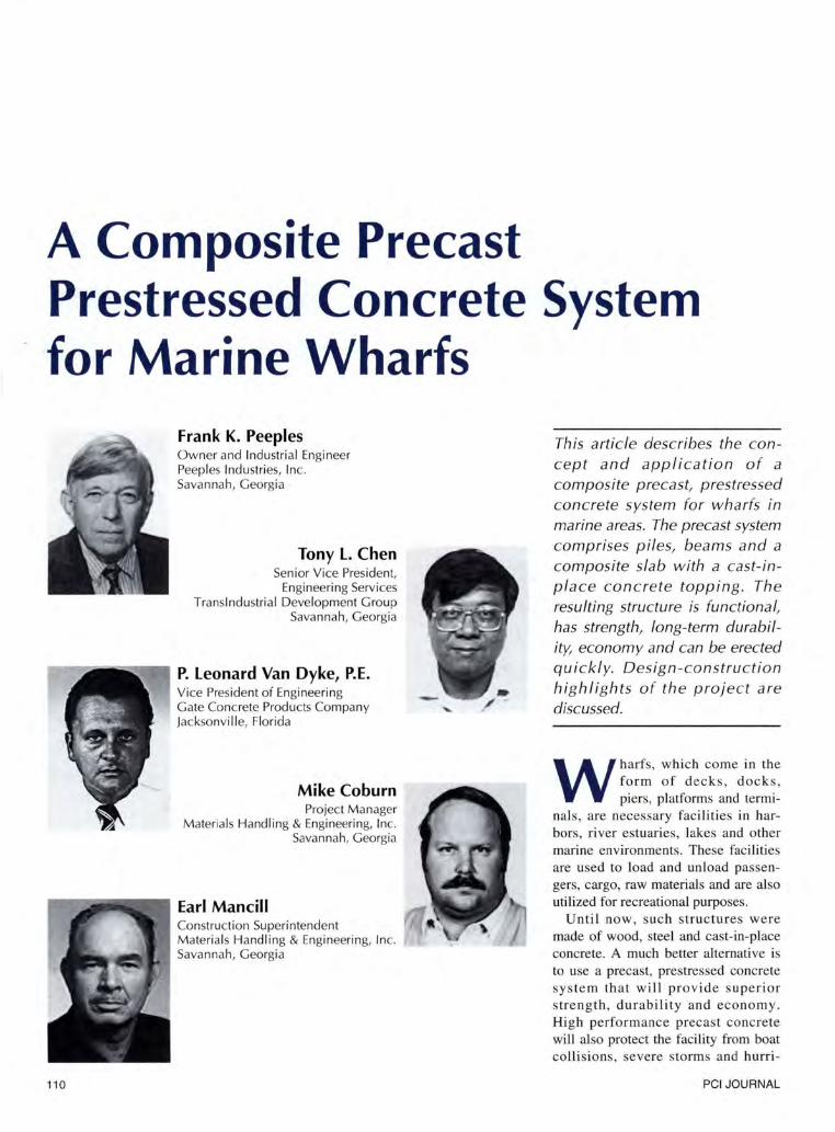
Fig. 1. Precast beam-to-straight pile connection. Piles are driven or cut off to the elevation as specified for the precast beam to sit on.
ships. The wharf addition was part of an expansion project for Sumitomo Corporation of America , which will use SBI as it' s Savannah Load Center. Translndustrial Development Group is an engineering design/build firm specializing in Marine Terminal Facilities for bulk material handling.
In the past, marine terminal wharfs consisted of wood and steel piles. A reinforced concrete deck was then poured on top of the steel piles. Due to
13"
the effects of a corrosive salt environment on the cast-in-place concrete deck and steel piles, the cost of maintaining this type of wharf can become prohibitively expensive.
One of the inherent problems in constructing a new wharf at an existing marine facility is that the construction of the new marine wharf cannot interrupt the busy on-going operations at the existing terminal. After a careful study of the shipping schedule and be-
BENT DOWELS AS REQUIRED
3'-3"
4'-0"
GROUT HOLE
PRECAST SLAB
4 #8 x 56" DOWELS
GROUT INTO 2" DIA HOLES
16x16 BATTER PILES
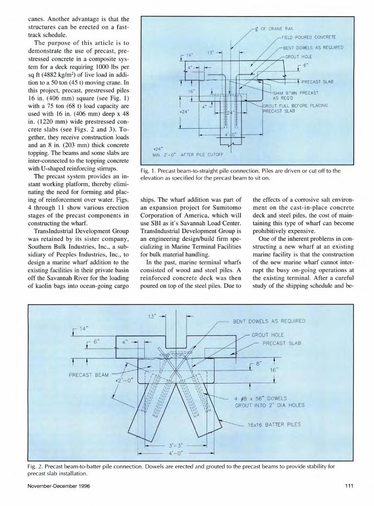
Fig. 2. Precast beam-to-batter pile connection . Dowels are erected and grouted to the precast beams to provide stability for precast slab installation.
November-December 1996 111
3'-0 ' 3'-0' ~
1'-4'
#8 @ 8' O.C.CTYP. AT RAIU NEGATIVE REJNF.
SEE VHARF PLAN FOR SLAB TOP REINF.
PROVI DE SHEAR CONNECTORS AT CANT . PRECAST SLAB
3' GROUT TUBE AT BM SPLICE V /(4)!l8X56 '
PRECAST BEAM SPLICE AT 24' DR 32 ' OR AT PRECASTER' S OPTION
Ci_ OF CRANE RAIL
CRANEVAY BEAMS
TYP. SL AB LDNGIT . TEMP. RE JNF. ENTIRE DOCK AREA ll4 I" 8'D.C.
BEAM
D.C .
DI A 270K . BOTTOM
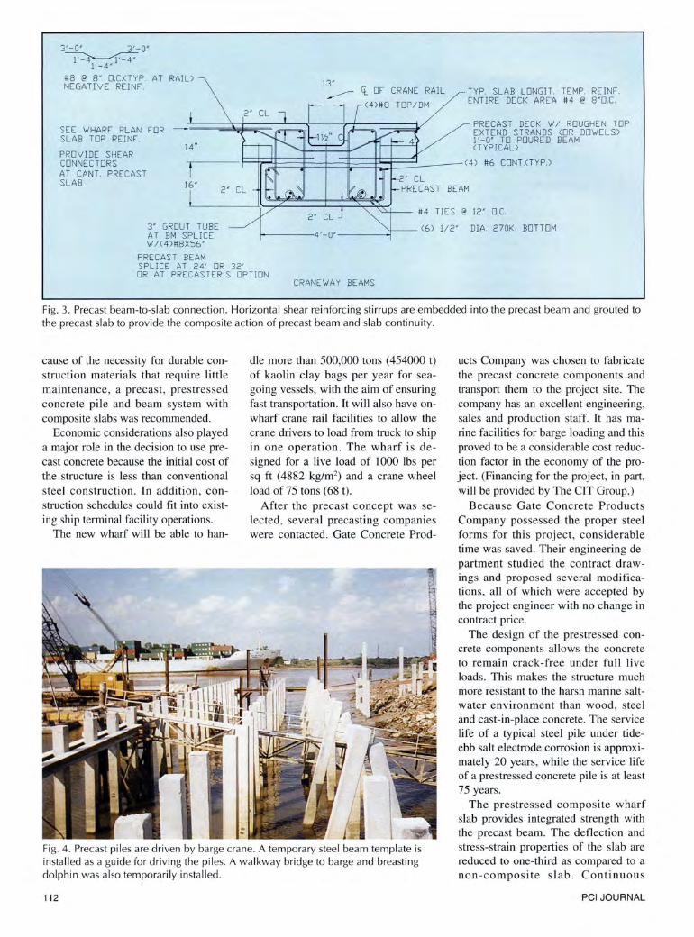
Fig. 3. Precast beam-to-slab connection . Horizontal shear reinforcing stirrups are embedded into the precast beam and grouted to the precast slab to provide the composite action of precast beam and slab continuity.
cause of the necessity for durable construction materials that require little maintenance, a precast, prestressed concrete pile and beam system with composite slabs was recommended.
Economic considerations also played a major role in the decision to use precast concrete because the initial cost of the structure is less than conventional steel construction. In addition, construction schedules could fit into existing ship terminal facility operations.
The new wharf will be able to han-
die more than 500,000 tons (454000 t) of kaolin clay bags per year for seagoing vessels, with the aim of ensuring fast transportation. It will also have onwharf crane rail facilities to allow the crane drivers to load from truck to ship in one operation. The wharf is designed for a live load of 1000 lbs per sq ft (4882 kg/m2
) and a crane wheel load of 75 tons (68 t).
After the precast concept was selected, several precasting companies were contacted. Gate Concrete Prod-
Fig. 4. Precast piles are driven by barge crane. A temporary steel beam temp late is installed as a guide for driving the piles. A walkway bridge to barge and breasting dolphin was also temporarily installed.
112
ucts Company was chosen to fabricate the precast concrete components and transport them to the project site. The company has an excellent engineering, sales and production staff. It has marine facilities for barge loading and this proved to be a considerable cost reduction factor in the economy of the project. (Financing for the project, in part, will be provided by The CIT Group.)
Because Gate Concrete Products Company possessed the proper steel forms for this project, considerable time was saved. Their engineering department studied the contract drawings and proposed several modifications , all of which were accepted by the project engineer with no change in contract price.
The design of the prestressed concrete components allows the concrete to remain crack-free under full live loads. This makes the structure much more resistant to the harsh marine saltwater environment than wood, steel and cast-in-place concrete. The service life of a typical steel pile under tideebb salt electrode corrosion is approximately 20 years, while the service life of a prestressed concrete pile is at least 75 years.
The prestressed composite wharf slab provides integrated strength with the precast beam. The deflection and stress-strain properties of the slab are reduced to one-third as compared to a non-composite slab. Continuous
PCI JOURNAL
beam/slab design decreased deflection and bending stresses by approximately 60 percent as compared to a noncomposite, simple span design. Consequently, the supporting piling spacing could be increased and the required size of members decreased.
The 28-day concrete strength for all members was 6000 psi (41 MPa). The high strength pile-wharf slab system also allowed increased bay sizes and fewer piles; thus, less pile driving was required. The precast slabs were designed to sustain construction loads immediately after placing. Precast fabrication reduced on-site construction man-hours and immediate wharf stability allowed the anchorage of ships during construction.
The design of a marine fender system depends on: • Ship gross weight • Velocity • Approach angle hydraulic and wind
effects The kinetic energy absorption of a
fender system requires a rubber system, which necessitates strong wharf mass inertia. A collision between a ship and the wharf is an elastic collision and the mass of piles and concrete deck play an important role in fender design. Prestressed concrete piling transfers the energy more effectively than steel piling.
WATERBORNE TRANSPORTATION
The precast concrete components were fabricated in the Gate Concrete Products plant in Jacksonville, Florida, next to waterfront property. The average cost for water transportation in the United States is considerably lower than that for truck or rail transportation. Three barge loads of precast components, each barge carrying I 000 tons (907 t) in weight, traveled from Jacksonville , Florida, to Savannah, Georgia, through an intracoastal waterway.
Railroad officials may argue that the actual cost of water transportation is greater than by rail transportation if federal subsidies in the form of navigation improvements are considered. However, the railroads also receive substantial subsidies in their opera-
November-December 1996
'
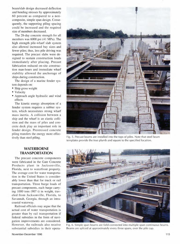
Fig. 5. Precast beams are installed into the tops of piles. Note that steel beam templates provide the true plumb and square to the specified location .
Fig. 6. Simple span beams are field-connected into multiple span continuous beams. Beams are spliced at approximate ly every three spans, over the pile cap.
113
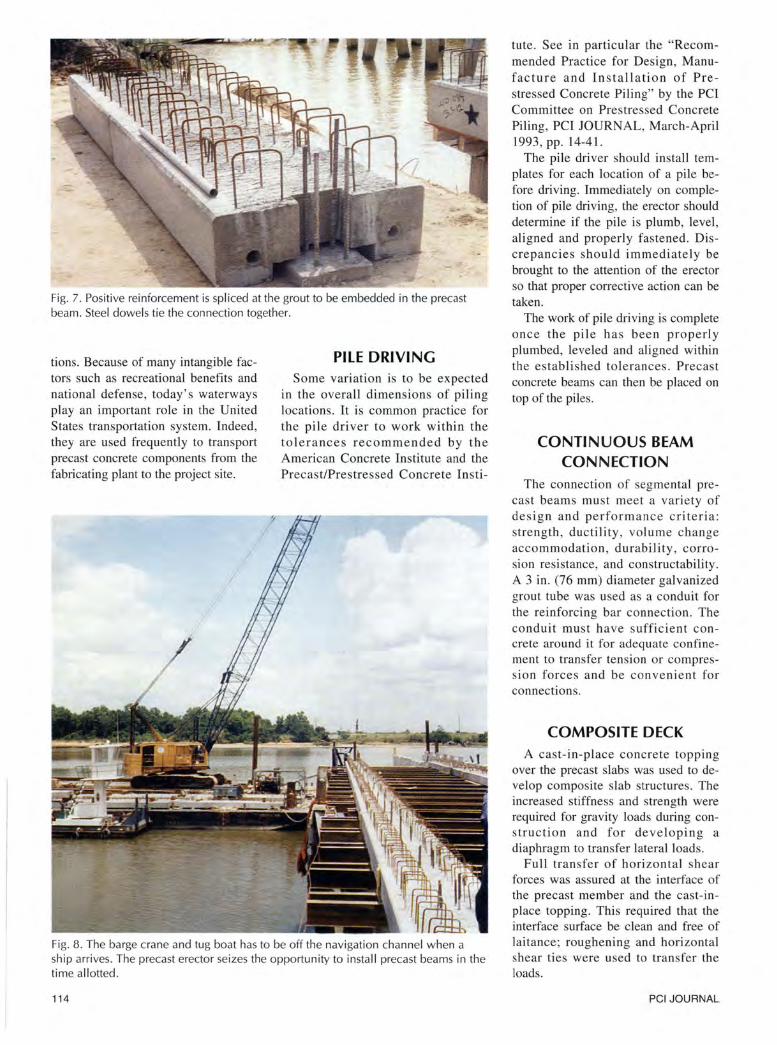
Fig. 7. Positive reinforcement is spliced at the grout to be embedded in the precast beam. Steel dowels tie the connection together.
tions. Because of many intangible factors such as recreational benefits and national defense, today' s waterways play an important role in the United States transportation system. Indeed, they are used frequently to transport precast concrete components from the fabricating plant to the project site.
PILE DRIVING Some variation is to be expected
in the overall dimensions of piling locations. It is common practice for the pile driver to work within the tolerances recommended by the American Concrete Institute and the Precast/Prestressed Concrete Insti-
Fig. 8. The barge crane and tug boat has to be off the navigation channel when a ship arrives. The precast erector seizes the opportunity to install precast beams in the time a ll otted.
114
tute. See in particular the "Recommended Practice for Design, Manufacture and Installation of Prestressed Concrete Piling" by the PCI Committee on Prestressed Concrete Piling, PCI JOURNAL, March-April 1993, pp. 14-41.
The pile driver should install templates for each location of a pile before driving. Immediately on completion of pile driving, the erector should determine if the pile is plumb, level, aligned and properly fastened. Discrepancies should immediately be brought to the attention of the erector so that proper corrective action can be taken.
The work of pile driving is complete once the pile ha s been properly plumbed, leveled and aligned within the established tolerances. Precast concrete beams can then be placed on top of the piles.
CONTINUOUS BEAM CONNECTION
The connection of segmental precast beams must meet a variety of design and performance criteria: strength, ductility , volume change accommodation, durability , corrosion resistance, and constructability. A 3 in . (76 mm) diameter galvanized grout tube was used as a conduit for the reinforcing bar connection. The conduit must have sufficient concrete around it for adequate confinement to transfer tension or compress ion forces and be convenient for connections.
COMPOSITE DECK A cast-in-place concrete topping
over the precast slabs was used to develop composite slab structures. The increased stiffness and strength were required for gravity loads during construction and for developing a diaphragm to transfer lateral loads.
Full transfer of horizontal shear forces was assured at the interface of the precast member and the cast-inplace topping. This required that the interface surface be clean and free of laitance; roughening and horizontal shear ties were used to transfer the loads.
PCI JOURNAL
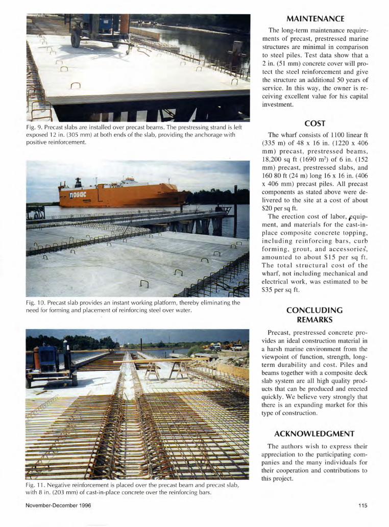
Fig. 9. Precast slabs are installed over precast beams. The prestressing strand is left exposed 12 in . (305 mm) at both ends of the slab, providing the anchorage with positive reinforcement.
Fi g. 10. Precast slab provides an instant working platform, thereby eliminating the need for forming and placement of reinforcing steel over water.
Fig. 11 . Negative reinforcement is placed over the precast beam and precast slab, with 8 in . (203 mm) of cast-in-place concrete over the reinforcing bars .
November-December 1996
MAl NTENANCE The long-term maintenance require
ments of precast, prestressed marine structures are minimal in comparison to steel piles. Test data show that a 2 in. (51 mm) concrete cover will protect the steel reinforcement and give the structure an additional 50 years of service. In this way, the owner is receiving excellent value for his capital investment.
COST The wharf consists of 1100 linear ft
(335 m) of 48 x 16 in. (1220 x 406 mm) precast, prestressed beams , 18,200 sq ft (1690 m2
) of 6 in. (152 mm) precast, prestressed slabs, and 160 80ft (24 m) long 16 x 16 in. (406 x 406 mm) precast piles. All precast components as stated above were delivered to the site at a cost of about $20 per sq ft.
The erection cost of labor, Fquipment, and materials for the cast-inplace composite concrete topping , including reinforcing bars, curb forming , grout, and accessories', amounted to about $15 per sq ft. The total structural cost of the wharf, not including mechanical and electrical work, was estimated to be S35 per sq ft.
CONCLUDING REMARKS
Precast, prestressed concrete provides an ideal construction material in a harsh marine environment from the viewpoint of function , strength, longterm durability and cost. Piles and beams together with a composite deck slab system are all high quality products that can be produced and erected quickly. We believe very strongly that there is an expanding market for this type of construction.
ACKNOWLEDGMENT
The authors wish to express their appreciation to the participating companies and the many individuals for their cooperation and contributions to this project.
115