Embed Size (px)
Citation preview

Insights into portability issues of FM3TR waveform
Frederic Le Roy1 • Lahatra Rakotondrainibe2 • Jean-Philippe Delahaye3 • Ali Mansour1
Received: 30 November 2015 / Revised: 15 May 2017 / Accepted: 13 December 2017� The Author(s) 2017. This article is an open access publication
AbstractThis manuscript focuses on issues related to the implementation of the Future Multiband Multiwaveform Modular Tactical
Radio (FM3TR) waveform on two different SCA platforms with similar hardware but different SCA development and
deployment environments. Our experimental results showed that a SCA standardization based on technologies such as
CORBA, XML, IDL, is not enough to ensure the portability of the waveform. Indeed, the files generated by SCA 2.2.2
environments (ZCE, SCA Architect, http://nordiasoft.com/products/scari-software-suite/sca-architect/) may often use a
specific non-standard IDL interface to generate software components. To corroborate our statement, specific examples of
SCA components are considered. The portability of the waveform depends on the waveform software used by the porting
team. Three classic cases can be observed during the development of a waveform according to a standard specification: The
first case is related to waveform development from scratch, the second case is observed when a static library is used to
carry the golden code of the waveform and the third one occurs when only platform specific codes are available to the
porting process. Finally, a general discussion about portability is provided.
Keywords Software defined radio (SDR) � Software communications architecture (SCA) � Waveform portability �Model driven engineering (MDE) � CORBA
1 Introduction
In many SDR projects, the waveform (WF) portability has
been investigated [2] and identified by portable code that
may reduce implementation time, money and effort and
save budget investments. Over the last decade, researchers
from all around the world have been involved in the con-
cept of portable codes. In ‘‘Wireless Innovation Forum:
Top 10 Most Wanted Wireless Innovations’’ [3], porting
activity was at the top of the list.
The porting concept was mainly introduced to improve
the interoperability among various radio systems using a
single code source that can be run on various platforms. In
this study, the analysis of executive settings is investigated
and several areas related to WF design are also considered
(such as the glue code generation, IDL, CORBA messaging
and Model of Computation (MoC) of ‘‘pipelined
components’’).
In this manuscript, three types of SCA [4] component
software design architecture and source code generation
are considered. Architectures of WF and platforms used in
this porting work are introduced. In addition, this manu-
script describes porting situations and proposes a Model
Driven Engineering (MDE) tool chain prototype to port
SCA waveforms on various platforms. Hereinafter, the
porting limitations observed in our experiments are
analyzed.
It is worth mentioning that our study showed how hard
can be the porting of a target waveform even thought it was
based on standardized software architecture. However,
Model-Driven Architecture (MDA) can provide various
& Frederic Le Roy
Lahatra Rakotondrainibe
Jean-Philippe Delahaye
Ali Mansour
1 ENSTA Bretagne, 2 Rue Francois Verny, 29806 Brest Cedex,
France
2 Thales Belgium S.A, Rue des Freres Taymans 28,
1480 Tubize, Belgium
3 DGA-MI, BP 7, 35998 Rennes Cedex 9, France
123
Analog Integrated Circuits and Signal Processinghttps://doi.org/10.1007/s10470-017-1097-x(012 3456789().,- volV)(0123456789().,-volV)

tools (Rapsody, MDWorkbench, Modelio, QVT, …) based
on meta-models allowing the transform of code models
using transformation rules which can take into account the
specificities of a platform and could release a comparison
report to enhance major differences between original and
target platforms.
The rest of this paper is presented as follows; Sect. 2
gives an overview of issues existed with the porting of
Software Communication Architecture (SCA) waveforms
and it also presented the proposed solutions of these issues
in the literature. In Sect. 3, three examples of software
component generation are presented to illustrate the dif-
ference that can be obtained by three generation environ-
ments yet based on the same SCA standard. In the Sect. 4,
we analyze the porting of a FM3TR waveform between
two different platforms. In Sect. 5, portage limitations
related to the compatibility among waveforms and plat-
forms are considered. Finally, Sect. 6 presents Model-
Driven Architecture (MDA) tools which could ease the
portage of a target code, developed on a given platform, to
a different platform.
2 Overview of portability concerns in SDR
In this section, different aspects of SDR WF design
impacting the portability are presented. In the context of
Software Defined Radio (SDR), the WF design should be
obtained on real time embedded systems, so software
portability can be considered as a multi-aspect problem.
The first aspect is related to the variety of digital signal
processing resources used in SDR. In [1], the authors
present a survey of various hardware platforms proposed in
US military SDR projects with different technical approa-
ches used during the last two decades. In these projects,
different Processing Elements (PE) are used such as:
General Purpose Processor (GPP), Digital Signal Processor
(DSP), Field Programmable Gate Array (FPGA), System
on Chip, (SoC), etc. By combining different PE technolo-
gies in a heterogeneous reconfigurable hardware in SDR
platforms, recent SDR architectures can make a trade off
among the overall performance, the power consumption or
the flexibility. The variety of these heterogeneous and
distributed architectures implies different allocations of
WF functions and codes among platform nodes which
limits the WF portability. Others technologies such as
MPSoCs (Multi Processor System on Chips), multicore,
manycore processors, or NoCs (Network on Chips) will be
introduced in next SDR platforms. Another aspect of SDR
platforms impacting software portability is the use of
middleware over the SDR platform hardware. Middleware
should help application programming and software porta-
bility by providing a high level of abstraction and a
uniform access over distributed hardware [5]. The most
important aspects for WF portability is the support of
standardized platform services given by e.g. SCA [1] and
ESSOR Architectures [6], to satisfy a wide variety of WFs.
The abstraction and standardization should be done over
the entire SDR Platform hardware as recommended by the
ESSOR architecture extensions on OE (Operating Envi-
ronment) Services for DSP, FPGA, additional APIs defin-
ing Radio Devices and Radio Services to solve the WF
portability challenges.
Recent studies on the WF proposed important develop-
ments concerning portability. The SCA Domain Specific
Modeling tools that generate SCA compliant source codes
is one of these important portability enablers. In fact, these
tools enable WF development methodologies and they are
composed of design guidelines associated to the WF soft-
ware development process.
According to [4], the ESSOR methodology is introduced
to define the WF portability. Taking into account the
diversity of platform architectures, this methodology
allows a common waveform to be developed and shared
among several actors. Therefore, the ESSOR methodology
relies on ‘‘BaseWF/TargetWF’’ design approach, where the
‘‘BaseWF’’ is the portable object. This two-step approach
can generate, at the ‘‘BaseWF’’ level, a software code
independent from any target platform supported by a WF
Platform Independent Model (PIM) modeling language
profile [7]. According to [6], the ESSOR methodology for
portability is generic, and it is elaborated to design and
validate the ‘‘BaseWF’’ with respect to the ESSOR
Architecture.
The different kinds of PE imply dealing with different
programming approaches and languages such as: C/C??
for GPP and DSP, VHDL for FPGA. This aspect limits the
waveform portability as discussed in [2].
The rest of the paper presents detailed insights into
waveform portability, especially a discussion on the SCA
component design with related design tools and some
platform aspects in regard to a porting experience of a
waveform.
3 SCA component generation
A main objective of the SCA specification is the definition
of an Operating Environment (OE) for a software radio
terminal. This OE defines a set of software interfaces that
forms the SCA v2.2.2 Core Framework (CF) and other
software architecture elements such as the Application
Environment Profile (AEP). The SCA v2.2.2 also relies on
technological choices such as XML Language for the
Domain Profile, Object Oriented technologies, Design
Patterns and UML Language.
Analog Integrated Circuits and Signal Processing
123

The CF of the SCA specification is mainly defined by its
interfaces (API). The CF controls, manages, and deploys
the waveform on a SDR platform. In the context of a JTR
(Joint Tactical Radio) System, ‘‘a waveform is used to
describe the entire set of functions that occurs from the user
to the RF output and vice versa’’. An implementation of a
waveform is a list of interconnected SCA component
producing services [4].
The component design is based on meta-models defined
within each code generation tool. These meta-models can
be very different from one tool to another despite the fact
that the tools are compliant with SCA coding rules, com-
ponent definitions, interfaces and XML files of the
‘‘DomainProfile’’.
3.1 SCA component definition
In SCA, the concept of component is mainly defined by the
IDL used to describe the SCA interfaces and by the XML
used to create the SCA Domain Profile elements which
identify the capabilities, properties, inter-dependencies,
and location of the hardware devices and software com-
ponents that make up a ‘‘SCA-compliant system’’ [4]. API
standards explicitly define the port concept required to
deploy software components in SDR platforms. The
authors of [1] showed that SCA components inherit a set of
interfaces defined in the Core Framework (CF). To
exchange data, the software components communicate
using ports of processing services, such as: port Provide or
port Use. These ports inherit from their SCA standard
interfaces and they must implement service packages
allowing the CF to manage interconnection, configuration,
testing and lifecycle of software components.
Each component has a well-defined set of ports specified
by two settings:
1. The first one is the service type setting. For example,
an ‘‘input port’’ or ‘‘provide’’ port can receive requests
from a component ‘‘output port’’ or use port. An ‘‘input
port’’ should wait for remote calls to produce its
service (server side). On the other hand, an output port
represents the client side that triggers requests to the
server side. In the context of waveform datapath,
output ports send data, while input ports receive
requests.
2. The second one is the data type setting carried by ports.
These two settings can be defined using interfaces. These
ones can be standard APIs or custom one. Creating a
custom interface in IDL allows the designer to choose, for
instance, the interface name, the associated methods, and
data types.
3.2 Implementation possibilities
In a SCA development tool chain, the implementation
containers of SCA components can be generated by a code
generator. In our experiments, three implementation con-
cepts of SCA component are considered:
1. In the first scheme, the SCA component class special-
izes the ‘‘Resource’’ class of the CF.
2. A second scheme separates the functionalities of a
SCA component and its ports.
3. The last one consists in distributing the component’s
services on its possible ports.
The three concepts are developed from the study of three
SCA Domain Specific Modeling tools: ‘‘OSSIE’’, ‘‘SCA
Architect’’ and ‘‘Zeligsoft CE’’ v2.4 (ZCE). The codes
generated by these three concepts conform to SCA speci-
fications; however, the code portability depends on the
implementation choices. The drawback of the first concept
is that the waveform functional code or business code is
mixed with the platform non-functional code or glue code
(SCA code). From the portability point of view, the second
concept is better because it separates the functional code
and the glue code also called the SCA container. However,
this separation affects the size of the generated code. The
last concept does not provide the separation of concerns, it
does not respect the concept of encapsulation of software
components and it maximizes porting complexity of a
waveform.
The choice of software component implementing model
is strongly linked to the choice of SCA Domain Specific
Modeling tools.
The second choice can promote the exchange and the
understanding within a team of developers using the same
chain of tools. However, when the chain is changed, the
compatibility of codes is no longer satisfied and the func-
tional code must be manually integrated into the generated
component container.
3.3 Example of code generation
To illustrate the second concept presented above, three
generation examples based on ‘‘OSSIE’’ [8], ‘‘ZCE’’ [9]
and ‘‘SCA Architect’’ [10] are presented. Although, they
are based on the same concept but implementations can be
different.
3.3.1 OSSIE example
The software component generated by the OEF (OSSIE
Eclipse Feature) for the interface of Fig. 1 produces three
C?? files: A file for the component class declaration, the
second file and the last one ‘‘main.cpp’’ are required to start
Analog Integrated Circuits and Signal Processing
123
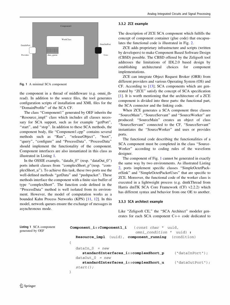
the component in a thread of middleware (e.g. omni_th-
read). In addition to the source files, the tool generates
configuration scripts of installation and XML files for the
‘‘DomainProfile’’ of the SCA CF.
The class ‘‘Component1’’ generated by OEF inherits the
‘‘Resource_impl’’ class which includes all classes neces-
sary for SCA support, such as for example ‘‘getPort’’,
‘‘start’’, and ‘‘stop’’. In addition to these SCA methods, the
component body, file ‘‘Component1.cpp’’ contains several
methods such as ‘‘Run’’, ‘‘releaseObject’’, ‘‘boot’’,
‘‘query’’, ‘‘configure’’ and ‘‘ProcessData’’. ‘‘ProcessData’’
should implement the functionality of the component.
Component interfaces are also instantiated in this class as
illustrated in Listing 1.
In the OSSIE example, ‘‘dataIn_0’’ (resp. ‘‘dataOut_0’’)
ports inherit classes from ‘‘complexShort_p’’(resp. ‘‘com-
plexShort_u’’). To achieve this task, these two ports use the
well-defined methods ‘‘getData’’ and ‘‘pushpacket’’. These
methods interface the component with a finite size buffer of
type ‘‘complexShort’’. The function code defined in the
‘‘ProcessData’’ method is well isolated from its environ-
ment. However, the model of computation works as a
bounded Kahn Process Networks (KPN) [11, 12]. In this
model, network queues ensure the exchange of messages in
asynchronous mode.
3.3.2 ZCE example
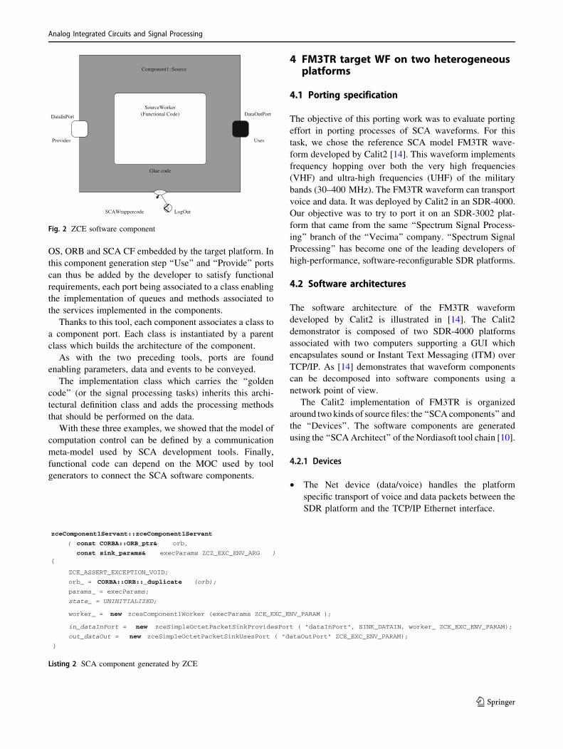
The description of ZCE SCA component which fulfills the
concept of component container (glue code) that encapsu-
lates the functional code is illustrated in Fig. 2.
ZCE adds proprietary infrastructure and scripts (written
by developers) to make Component Based Software Design
(CBSD) possible. The CBSD offered by the Zeligsoft tool
addresses the limitations of IDL2.0 based design by
establishing architectural choices for component
implementations.
ZCE can integrate Object Request Broker (ORB) from
different providers and various Operating System (OS) and
CF. According to [13]; SCA components which are gen-
erated by ‘‘ZCE’’ satisfy the concept of SCA specification
[1]. It is worth mentioning that the architecture of a ZCE
component is divided into three parts: the functional part,
the SCA connector and the linking code.
When ZCE generates a SCA component three classes
‘‘SourceMain’’, ‘‘SourceServant’’ and ‘‘SourceWorker’’ are
produced: ‘‘SourceMain’’ creates an object of class
‘‘SourceServant’’ connected to the CF, ‘‘SourceServant’’
instantiates the ‘‘SourceWorker’’ and uses or provides
ports.
The functional code describing the functionalities of a
SCA component must be completed in the class ‘‘Source-
Worker’’ according to coding rules of the waveform
designer.
The component of Fig. 1 cannot be generated in exactly
the same way by two environments. As illustrated Listing
2, ports implement specific classes ‘‘SimpleOctetPack-
etSink’’ and ‘‘SimpleOctetPacketUses’’ that are specific to
ZCE. Moreover, the functional code of the worker class is
executed in a lightweight process (e.g. dmtkThread from
Harris dmTK SCA Core Framework (CF) v2.2.2) which
has different syntax and behavior from one OE to another.
3.3.3 SCA architect example
Like ‘‘Zeligsoft CE,’’ the ‘‘SCA Architect’’ modeler gen-
erates for each SCA component C?? code dedicated to
DataInPort DataOutPort
Provides Uses
WorkClass
data_queue
Component1
Fig. 1 A minimal SCA component
(Component_i::Component1_i const char *omni_condition *
uuid,uuid) :
Resource_impl (uuid), component_running (condition)
{
dataIn_0 = newstandardInterfaces_i::complexShort_p ("dataInPort");
dataOut_0 = newstandardInterfaces_i::complexShort_u ("dataOutPort");
start();}
Listing 1 SCA component
generated by OEF
Analog Integrated Circuits and Signal Processing
123
OS, ORB and SCA CF embedded by the target platform. In
this component generation step ‘‘Use’’ and ‘‘Provide’’ ports
can thus be added by the developer to satisfy functional
requirements, each port being associated to a class enabling
the implementation of queues and methods associated to
the services implemented in the components.
Thanks to this tool, each component associates a class to
a component port. Each class is instantiated by a parent
class which builds the architecture of the component.
As with the two preceding tools, ports are found
enabling parameters, data and events to be conveyed.
The implementation class which carries the ‘‘golden
code’’ (or the signal processing tasks) inherits this archi-
tectural definition class and adds the processing methods
that should be performed on the data.
With these three examples, we showed that the model of
computation control can be defined by a communication
meta-model used by SCA development tools. Finally,
functional code can depend on the MOC used by tool
generators to connect the SCA software components.
4 FM3TR target WF on two heterogeneousplatforms
4.1 Porting specification
The objective of this porting work was to evaluate porting
effort in porting processes of SCA waveforms. For this
task, we chose the reference SCA model FM3TR wave-
form developed by Calit2 [14]. This waveform implements
frequency hopping over both the very high frequencies
(VHF) and ultra-high frequencies (UHF) of the military
bands (30–400 MHz). The FM3TR waveform can transport
voice and data. It was deployed by Calit2 in an SDR-4000.
Our objective was to try to port it on an SDR-3002 plat-
form that came from the same ‘‘Spectrum Signal Process-
ing’’ branch of the ‘‘Vecima’’ company. ‘‘Spectrum Signal
Processing’’ has become one of the leading developers of
high-performance, software-reconfigurable SDR platforms.
4.2 Software architectures
The software architecture of the FM3TR waveform
developed by Calit2 is illustrated in [14]. The Calit2
demonstrator is composed of two SDR-4000 platforms
associated with two computers supporting a GUI which
encapsulates sound or Instant Text Messaging (ITM) over
TCP/IP. As [14] demonstrates that waveform components
can be decomposed into software components using a
network point of view.
The Calit2 implementation of FM3TR is organized
around two kinds of source files: the ‘‘SCA components’’ and
the ‘‘Devices’’. The software components are generated
using the ‘‘SCAArchitect’’ of the Nordiasoft tool chain [10].
4.2.1 Devices
• The Net device (data/voice) handles the platform
specific transport of voice and data packets between the
SDR platform and the TCP/IP Ethernet interface.
DataInPort DataOutPort
Provides Uses
SCAWrappercode LogOut
(Functional Code)SourceWorker
Glue code
Component1::Source
Fig. 2 ZCE software component
zceComponent1Servant::zceComponent1Servant
( const CORBA::ORB_ptr& orb,
const sink_params& execParams ZCZ_EXC_ENV_ARG ){
ZCE_ASSERT_EXCEPTION_VOID;
orb_ = CORBA::ORB::_duplicate (orb);
params_ = execParams;
state_ = UNINITIALIZED;
worker_ = new zcesComponent1Worker (execParams ZCE_EXC_ENV_PARAM );
in_dataInPort = new zceSimpleOctetPacketSinkProvidesPort ( "dataInPort", SINK_DATAIN, worker_ ZCE_EXC_ENV_PARAM);
out_dataOut = new zceSimpleOctetPacketSinkUsesPort ( "dataOutPort" ZCE_EXC_ENV_PARAM);
}
Listing 2 SCA component generated by ZCE
Analog Integrated Circuits and Signal Processing
123

• The Modem device is compliant to Modem Hardware
Layer (MHAL) modem API. It encapsulates (or
extracts) voice and data to MHAL frames. These
frames are exchanged with non-CORBA components.
4.2.2 SCA components
• The Continuously Variable Slope Delta modulation
(CVSD) codec is a voice variable step coding and
decoding component.
• The Data Link Control (DLC) segments and reassem-
bles voice and data messages. It implements the
classical Automatic Repeat reQuest (ARQ) network
protocols.
• The Reed-Solomon (RS) is a SCA resource that
encodes outgoing data packets into a RS block code
and decodes received RS encoded blocks.
• The data Media Access Control (MAC) converts the
format between MHAL frames to match the RS
encoding format.
• The voice MAC converts the format between voice
samples and MHAL frames.
4.3 Platform architecture and mapping
4.3.1 SDR-4000 architecture
The Calit2 demonstrator platform combines the SDR-4000
with a ‘‘National Instrument’’ PXI system for the frequency
transposition. This PXI system consists of:
• A card ‘‘PXI-5610 Up-converter’’,
• A card ‘‘PXI-5600 Down-converter’’.
Application or platform components are implemented in
the GPP processor card PRO-4600 subsystem SDR-4000.
The non CORBA processing base band signal component
is implemented in the TMS320C6416 processor PRO-4600
card while the frequency translation component is done
using the Virtex-4 of the XMC-3321 card.
4.3.2 SDR-3002 architecture
The architecture of the platform (SDR-3002) used in our
project is illustrated in Fig. 3. The entire system consists of
a combination of a SCA subsystem and a transceiver
subsystem. The transceiver subsystem is a part of the radio
chain that converts the baseband into a radio signal for
transmission and converts the radio signal into a baseband
signal for reception.
The SDR-3002 platform consists of two integrated
subsystems in the same cPCI chassis.
The DRT-4001 consists of an amplifier subsystem and a
transceiver (transceiver) radio frequency that transposes an
intermediate frequency signal up to 3 GHz. The Radio
Frequency (RF) signal to be transposed into the DRT-4001
should be centered on an Intermediate Frequency (IF) of
70 MHz. The RF signal received by the DRT-4001 is
transposed to 17.5 MHz.
The sub SDR-3002 system consists of:
• The TM1-3350 grabber radio signal (both channels
ADC and two DAC channels).
• The SBC board (a Single Processor Board) with a x86/
Win (Host PC) processor.
• The PRO-3100 board that has four Xilinx Virtex-II, a
power PC 405 and an Ethernet interface.
• An Ethernet board with a GPS receiver.
4.3.3 Mapping and results
The challenge of SCA FM3TR waveform portability, based
on the CALIT 2 SCA waveform is illustrated in [14]. The
ZCE model obtained is illustrated in appendix.
The transfer methodology of application code used in
the ZCE model consists of:
1. Searching for equivalences between the port types
available in ZCE and port types used in the target code.
2. Creating the corresponding SCA model components
and waveform.
3. Generating source code for each SCA component of
the waveform.
4. Adding the functional code manually to ZCE SCA
components.
We have mapped the following waveform on the SDR-
3002 platform (Table 1).
In this mapping phase, the use of ‘‘ZCE’’ instead of
‘‘SCA architect’’ initially used by the Calit2 team made the
porting process difficult to be manually managed.
5 Observed porting limits
Hereinafter, the limitations observed of the development
tools, middleware and platforms are discussed.
5.1 Development tool limitations
The limitations observed originate from component inter-
faces and architecture.
Analog Integrated Circuits and Signal Processing
123

5.1.1 Component interfaces
The SCA compliant platform comes with its BSP (Board
Support Package), its devices and its Software Develop-
ment Kit (SDK). As indicated by SCA specification,
devices and component interfaces may be abstracted by
additional specific interfaces that warranty the indepen-
dence of a software waveform to platform services. How-
ever, BSP and SDK libraries called upon by SCA tools in
the generation process of the software components can use
specific IDL which is not defined in the SCA CF interface.
In the next example, three IDL interfaces generated by
three different SCA development tools are provided.
Listing 3 shows that for similar services of data
exchange, different interface definitions with behavior
difference are used and supported by Platforms. This rep-
resents an additional porting effort to adapt from one to
another and it becomes sometimes difficult to be satisfied.
However, this porting can be achieved by importing
specific libraries from the first tool/platform to the second
or by redesigning the waveform accordingly to fit this
specific interface. This experience shows that the use of
different IDL interface definitions among different SCA
platforms limits the portability event if tool chains help to
perform the required transformation.
5.1.2 Component architecture
The SCA specifies that components inherit the ‘‘Resource’’
class from the SCA CF. A component must implement
‘‘use’’ and ‘‘Provide’’ ports (see Fig. 1). However, the SCA
specification does not specify details about the implemen-
tation. Therefore, the designer can freely implement the
required components.
DACDAC
DAC
ADCADC
ADC
TM1−3350
FPGA
FPGA
FPGA
FPGA
PPC
PPC
PRO−3500PRO−3100
Analog IFfrequency
Digital IFfrequency
Basebanddata encoded
DRT−4001
Highfrequency
4011B
4011B
Antenna
SDR 3002 Platform
Fig. 3 SDR-3002 platform
Table 1 Waveform mapping on
the SDR-3002Component Board Target circuit OS
cvsd PRO3500 P0, PPC7410 VxWork
datamac PRO3500 P0, PPC7410 VxWork
fm3trcontroller SBC Pentium Windows
mac PRO3500 P0, PPC7410 VxWork
nspr842_duc PRO3100 XC2V3000 Virtex-II, SAND 0 VxWork
nspr842_ddc PRO3100 XC2V3000 Virtex-II, SAND 3 VxWork
rs PRO3500 P0, PPC7410 VxWork
net SBC Pentium Windows
voiceNet SBC Pentium Windows
modem_device PRO3500 P0, PPC7410 VxWork
Analog Integrated Circuits and Signal Processing
123
In the case of the ‘‘ZCE’’ tool, code of an instance of a
‘‘worker’’ class runs functional code i.e. a part of a com-
ponent waveform. This approach separates the structural
from the functional parts of a software component. Indeed,
the ‘‘servant’’ class implements ‘‘Provide’’ ports that
implement interfaces of the processing task (CF::Re-
source). This separation of concerns is at the expense of
code expansion.
Another software design approach uses the interface by
encoding method. According to our third concept men-
tioned in Sect. 3.2, functionalities are embedded in the
implementations of a ‘‘class Port’’. The major drawback of
this approach is the loss of functional code visibility.
In our study, we distinguished between two types of
SCA component implementations. The first follows the
CBSD (Component-Based Software Development)
methodology while the second uses the customer separa-
tion/server provided by CORBA 2.x component. The first
approach improves the portability; but the designer is free
to define the implementation because the SCA standard
does not impose any constraint on the implementation
other than the use of CORBA.
5.2 CORBA and MOC limitations
SCA waveforms are made from a blend of software com-
ponents (application components, API devices and con-
trollers). This combination of software components usually
executes on target in a pipeline manner. SCA 2.2.2 relies
on CORBA; data transported by the CORBA bus provides
two types of messages: ‘‘One-way messaging’’ and the
‘‘two-way messaging’’. The authors of [15] describe the
problem of ‘‘pipeline’’ vacuum related to the use of ‘‘two-
way messaging’’. They also describe how ‘‘one-way
messaging’’ can be used to limit the impact of the empty
pipeline on throughput and processing latency. ‘‘One-way
messaging’’ is usually considered to be a better approach to
increase processing rate. Finally, solutions such as flow
control mechanism for ‘‘one-way messaging’’ and
‘‘threads’’ using ‘‘two-way messaging’’ are proposed to
address drawbacks.
According to the middleware used by SCA CF (e.g.
TAO or omniORB, etc.), ORB settings acts significantly on
the waveform portability. Indeed, this action changes the
model of computation (MOC) [12] of component message
exchanged in waveform applications.
5.3 Platform limitations
Processing boards inside SDR platform usually have a fast
specific link that can be used to bypass the CORBA bus.
For example, the ‘‘FlexFabric’’ examples of Fig. 4 are used
by Spectrum Signal systems for high-speed communication
between two processing resources of the SDR platform. As
illustrated in this figure, the connection between the ports
of the two components is associated with the use of an
abstract port called ‘‘DeviceThatLoadedThisCompo-
nentRef’’. For the SDR-3002 platform, the use of this port
in a ZCE model refers explicitly to the ‘‘FlexFabric’’ link in
the model. Thus, this type of connection modifies the
computation model of the waveform. Indeed, they can be
configured in point to point blocking and non-blocking
channels.
Using this type of connection limits the waveform
portability, because it is specific to the platform and it
modifies the scheduling of the execution or the computa-
tion model.
6 Proposal
The experiment that we have described has highlighted
certain limitations of the specific development tools, the
CORBA software bus used, as well as the BSP embedded
on the platforms. Our specifications summarized in the
table below consisted in porting a ‘‘Target OE I’’ type
waveform to another ‘‘Target OE II’’ type waveform (in
our case we port the ‘‘Target OE I’’ from the SDR-4000
platform to ‘‘Target OE II’’ to the SDR-3002 platform)
(Table 2).
As illustrated by the table above, the SCA code gener-
ation and waveform deployment tools are different. As it
can be seen, the porting operation remains particularly
delicate as the ‘‘Target OE I’’ type waveforms do not
generally rely on static libraries as advised in [16, 17]. The
portability of the waveform depends on the waveform
interface IoPacket{oneway void
(in };
interface SimpleOctetPacketSink{void pushPacket
(in NullControl unusedControl,in CF::OctetSequenceraises (
};
interface OctetStream :PayloadStatus{
void pushPacket(in StreamControlTypein JTRS::OctetSequence )raises ( UnableToComplete
PushPacketFailure
};
CF:OctetSequence pushPacket
payload );
)payload);
control,payload);
Listing 3 IDL definition for different Packet interfaces
Analog Integrated Circuits and Signal Processing
123

software used by the porting team. Three classic situations
can be observed:
1. When the waveform is to be developed from a
specification, a CIM (Computation Independent
Model) or a PIM (Platform Independent Model) on
one or several SCA compatible platforms.
2. When there is a static library used by a ‘‘Target OE I’’
type waveform and the waveform is to be ported onto
another OE to obtain a ‘‘Target OE II’’ type waveform.
3. The final, most usual yet most difficult possibility is
when only a ‘‘Target OE I’’ waveform source code and
its specification are available. It was within this context
that our porting took place.
Generally, any waveform artifact associated to a waveform
code delivery will help the porting process, as for example
Software Models, Functional WF Model, and WF
Simulation.
In the last paragraph, we will propose semi-automatic
processes based on MDA approaches which will ease a
waveform to be ported.
6.1 From a CIM or PIM model
When a waveform is to be developed from scratch, the
adoption of a Model-Driven Engineering (MDE)
methodology such as MoPCoM [18, 19] has numerous
advantages including easing the portability of a waveform.
Indeed, the association of meta-models in the processes
defines three levels of abstraction which enable a PSM
(Platform Specific Model) to be obtained at the end of the
process. This model is associated to a platform which can
be strongly heterogeneous.
This modeling process relies on the three following
abstract level: AML (Abstract Modeling Level), EML
(Execution Modeling Level), DML (Detailed Modeling
Level) layers, which respectively enable to test:
• The functional aspect of calculation model of the
waveform.
• The chronological sequencing of the operations on the
communication channels (bus).
• The chronological sequencing at cycle accurate
operation
The code generators associated to the MDA process also
enable the validation of the developments via the Elec-
tronic Design Automation (EDA) event simulator.
Unfortunately, the SCA modeling tools capacity for
importing or exporting models to commercially UML
modeler are often weak, whereas the SCA 2.2.2, SCA 4.1
and ‘‘upgrades’’ remain in the realms of the specialist. The
metamodels employed for the generation of SCA compo-
nent frames thus remain among the property knowledge of
the toolmakers as their own ‘‘business model’’.
6.2 From a ‘‘base OE’’ PSM model with a staticlibrary
This porting operation starts out from a ‘‘Base OE’’ type
PSM model, that is to say, a group of components often
written in C?? and generated by a SCA modeler. The
‘‘golden’’ codes of these components are then inserted by
<<component>>Source Sink
<<component>>
dataOut
fabric_dataOut
fabric_dataOut
fabric_dataIn
fabric_dataIn
dataIn
Fig. 4 Fast communication bus
illustrated in ZCE
Table 2 Operation environment
Target OE I Target OE II
Modeling tool SCA Architect Zeligsoft CE
CF SCARI?? Harris dmTK
OS Linux Windows XP
ORB TAO TAO
Analog Integrated Circuits and Signal Processing
123

the developer into the application code via a static library
which has been previously validated.
The first step of the process in Fig. 5 consists in vali-
dating the interconnection schemes from XML files,
nowadays often, produced by the SCA code generators.
These analyzers/parsers check the conformity of the SCA
models as well as the correspondence between the different
ports of the SCA models. The formats produced by the
SCA component extraction tools are, in this case, UML
models which can be checked by a ‘‘model checker’’. This
step produces two component diagrams (one for the ‘‘base
OE’’ and the other for ‘‘target OE’’ waveform) and a SCA
skeleton (wrappers and worker class) for each component
of the ‘‘base OE’’ waveform.
The second step uses the three last models, static library
carrying ‘‘golden code’’ and ‘‘base OE’’ component sour-
ces. The porting process (cf. Fig. 6) consists in carrying out
‘‘reverse engineering’’ of ‘‘base OE’’ and ‘‘target OE’’ to
make a C?? class models. This task can be done by most
of the commercially available UML modeler. After this sub
step, this model can then be used to associate the ‘‘golden
code’’ to ‘‘target OE’’ component diagram ports identified
in the first step. This is an annotation action that can be
done by UML transformer on the ‘‘target component dia-
gram’’. The last sub step can generate ‘‘target OE’’ C??
code from this ‘‘target OE’’ component diagram model and
from ‘‘target OE’’ C?? class diagram on the condition, of
course, of having a SCA implementation meta-model for
SCA component generation.
6.3 From a ‘‘Target OE’’ PSM model with no staticlibrary
This is a classic yet the most delicate situation to be
implemented. The results presented in Sect. 4 originate
from this type of situation. The process is quite similar to
that described in Sect. 6.2 except that it is impossible to
extract the functionalities from the static library. The
operation is thus much more complex in its execution as
the extraction of the ‘‘golden code’’ from the implemented
code is totally specific to the developer, and can only be
manually accomplished. The performance of the human
operator is thus pivotal yet variable according to his
knowledge of the two ‘‘base’’ and ‘‘target’’ OEs and also
the business code as well.
7 Conclusion
In this manuscript, we investigate the portability of FM3TR
waveform on SDR-3002. Initially, Calit2 implemented
FM3TR waveform on the SDR-4000. This platform is quite
similar to our target platform SDR-3002. Even though the
two platforms are similar, the portability of the code is not
an easy task. In fact, our experiments showed that the
generation of source codes depends on software develop-
ment kits (SDK), CORBA ORB, and OS for the imple-
mentation. We have to emphasize again that the execution
model is not defined in the SCA specification. This model
can be affected by the implementation of software
XML Base OE
UML modeler
Model checker
UML modelerChecker SCA
Generate
XML Parser
Diagram (XMI)
UML export
Target componentDiagram (XMI)
Base component
XML Target OE
Target OEempty C++ code
ComponentsInterfaces
InterconnectionsXML Parser
UML export
Import XMLCheck
SCA modeling tool
Fig. 5 First step of the ‘‘Base OE’’ PSM to ‘‘Target OE’’ PSM with static library
Analog Integrated Circuits and Signal Processing
123

components and the setting of the ORB. Accordingly, this
affects the waveform code portability by creating depen-
dencies on the platform.
Our experimental works demonstrate that the SCA
development tool chain (such as ‘‘Zeligsoft CE’’, ‘‘Spectra
CX’’ or ‘‘SCA Architect’’) improves the development of a
SCA waveform. However, the software configurations are
difficult (e.g.: dependency management, settings…), but
the code portability is partial between tool chain elements
and the portability at the model level becomes also poor.
We have shown in Sect. 6 that there are several situa-
tions of porting a waveform on a target platform. This
porting operation is more or less complex to automate
related to these situations. An almost automatic proposal
was proposed in the case of the use of a static library to
implement a golden code of SCA components.
Even if SCA specification enforces the uses of a large
set of Interfaces (mainly related to CF), the use of addi-
tional standardized APIs (Radio Devices and Radio Ser-
vices) represents a step beyond to cover all the waveform
needs but it is still not sufficient in terms of portability
requirement. Therefore, there are still difficulties to port a
waveform on a COTS platform because these products do
not provide ‘‘natively’’ a support for additional standard-
ized APIs.
Finally, we can observe the fact that selecting an
appropriate metamodel can help us to adapt the code to any
specific platform. This approach could be continued by
using the MDE approach which can help to manage the
development and the validation of SCA models better.
Open Access This article is distributed under the terms of the Creative
Commons Attribution 4.0 International License (http://creative
commons.org/licenses/by/4.0/), which permits unrestricted use, dis-
tribution, and reproduction in any medium, provided you give
appropriate credit to the original author(s) and the source, provide a
link to the Creative Commons license, and indicate if changes were
made.
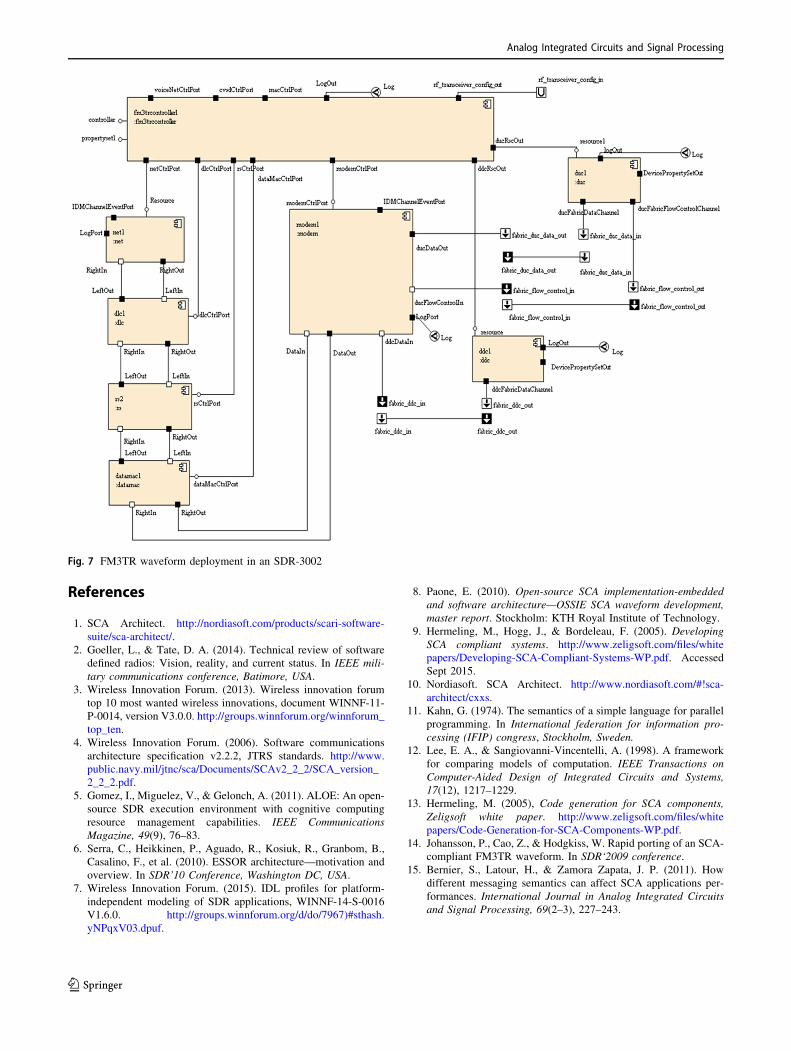
Appendix
See Fig. 7.
meta−model (XMI)SCA implementation
C++ codesTarget OE
UML modeler
Base OEC++ sources
Static Library (.a, .h)
UML modeler
Target OE
C++ Reverseengineering
C++ Reverseengineering
C++ Target Class
empty C++ code
Diagram (XMI)
C++ Base ClassDiagram (XMI)
Base component Target componentDiagram (XMI) Diagram (XMI)
Transformation
NavigationAnnotation
Annotated model
UML modeler
toolUML
Fig. 6 Second step of the ‘‘Base OE’’ PSM to ‘‘Target OE’’ PSM with static library
Analog Integrated Circuits and Signal Processing
123
References
1. SCA Architect. http://nordiasoft.com/products/scari-software-
suite/sca-architect/.
2. Goeller, L., & Tate, D. A. (2014). Technical review of software
defined radios: Vision, reality, and current status. In IEEE mili-
tary communications conference, Batimore, USA.
3. Wireless Innovation Forum. (2013). Wireless innovation forum
top 10 most wanted wireless innovations, document WINNF-11-
P-0014, version V3.0.0. http://groups.winnforum.org/winnforum_
top_ten.
4. Wireless Innovation Forum. (2006). Software communications
architecture specification v2.2.2, JTRS standards. http://www.
public.navy.mil/jtnc/sca/Documents/SCAv2_2_2/SCA_version_
2_2_2.pdf.
5. Gomez, I., Miguelez, V., & Gelonch, A. (2011). ALOE: An open-
source SDR execution environment with cognitive computing
resource management capabilities. IEEE Communications
Magazine, 49(9), 76–83.
6. Serra, C., Heikkinen, P., Aguado, R., Kosiuk, R., Granbom, B.,
Casalino, F., et al. (2010). ESSOR architecture—motivation and
overview. In SDR’10 Conference, Washington DC, USA.
7. Wireless Innovation Forum. (2015). IDL profiles for platform-
independent modeling of SDR applications, WINNF-14-S-0016
V1.6.0. http://groups.winnforum.org/d/do/7967)#sthash.
yNPqxV03.dpuf.
8. Paone, E. (2010). Open-source SCA implementation-embedded
and software architecture—OSSIE SCA waveform development,
master report. Stockholm: KTH Royal Institute of Technology.
9. Hermeling, M., Hogg, J., & Bordeleau, F. (2005). Developing
SCA compliant systems. http://www.zeligsoft.com/files/white
papers/Developing-SCA-Compliant-Systems-WP.pdf. Accessed
Sept 2015.
10. Nordiasoft. SCA Architect. http://www.nordiasoft.com/#!sca-
architect/cxxs.
11. Kahn, G. (1974). The semantics of a simple language for parallel
programming. In International federation for information pro-
cessing (IFIP) congress, Stockholm, Sweden.
12. Lee, E. A., & Sangiovanni-Vincentelli, A. (1998). A framework
for comparing models of computation. IEEE Transactions on
Computer-Aided Design of Integrated Circuits and Systems,
17(12), 1217–1229.
13. Hermeling, M. (2005), Code generation for SCA components,
Zeligsoft white paper. http://www.zeligsoft.com/files/white
papers/Code-Generation-for-SCA-Components-WP.pdf.
14. Johansson, P., Cao, Z., & Hodgkiss, W. Rapid porting of an SCA-
compliant FM3TR waveform. In SDR‘2009 conference.
15. Bernier, S., Latour, H., & Zamora Zapata, J. P. (2011). How
different messaging semantics can affect SCA applications per-
formances. International Journal in Analog Integrated Circuits
and Signal Processing, 69(2–3), 227–243.
Fig. 7 FM3TR waveform deployment in an SDR-3002
Analog Integrated Circuits and Signal Processing
123
16. Singh, S., Adrat, M., & Antweiler, M. (2009). NATO RTO/IST
RTG on SDR: Demonstrating portability and interoperability of
SCA-based waveforms. In SDR’09 conference.
17. Research Task Group on Software Defined Radios. (2012).
Software defined radio, RTO technical report, TR-IST-080.
https://www.cso.nato.int/abstracts.aspx?RestrictPanel=4.
18. Le Roy, F., Champeau, J., & Delahaye, J. P. (2011). A model
based methodology for SCA waveform design enhancing porta-
bility: Application to the FM3TR waveform application. In
WInnComm Europe’11 conference.
19. Koudri, A., Champeau, J., Aulagnier, D., & Vojtisek, D. (2009).
Processus de developpement UML/MARTE MoPCom pour le
codesign, Genie Logiciel.
Frederic Le Roy was born in
Landerneau, France, in 1971.
He received the Master and
Ph.D. degrees in electronic from
the University of Brest, France,
in 1995 and 2000 respectively.
He spends his Ph.d period at the
actual PRACOM laboratory of
Ecole Nationale Superieure des
Telecommunication de Bre-
tagne (ENST Bretagne, France).
His research was made in col-
laboration with the international
company France Telecom R&D
on High Level Synthesis
methodologies for asynchronous circuits design. In 2000–2001 he
worked at Institut Superieure de l’Electronique et du Numerique
(ISEN Brest) for five years where he was involved in industrial few
projects of telecommunication and was the principal advisor for the
bachelor grade. Since 2006, he has been an associate Professor at
Model Driven Engineering team of Ecole Nationale Institute des
Techniques Avancees, Brittany (Ensta Bretagne), Brest, France,
where he teaches computer science engineering and telecommunica-
tion. Actually, his research interests are in high performance of cir-
cuits and systems design and performance analysis for software and
cognitive radio design.
Lahatra Rakotondrainibe In
2010, Lahatra Rakotondrainibe
(LR) received his PhD degree in
Electronics from the IETR/
INSA university (France). He
has been involved in Millimetter
waves (60 GHz) and radio cog-
nitive projects. In September
2010, he joined the research
REMS (Radar Electromagnetic
and Remote Sensing) team of
ENSTA Bretagne (France). He
was implied in the development
of the wideband Ku-radar and
GNSS receiver platforms. In
September 2011, he joined the research MDE (Model Driven Engi-
neering) team of ENSTA Bretagne laboratory. He was implied in the
reverse engineering project to ensure the waveform portability and the
conformity to SCA standard. Since October 2012, he is implicated in
Defence HF/RF communications, wireless telemetry and ETCS pro-
jects at Thales Communications Belgium.
Jean-Philippe Delahaye receivedhis MS in Telecommunications
from the National Institute of
Telecommunications ‘‘Telecom
SudParis’’ and his Master
Degree in Electronics from the
University of Paris 11, both in
2003. He received his Ph.D.
Degree in Electronics from the
University of Rennes 1, France
in 2007 with research interest
focused on reconfigurable
heterogeneous architecture in
SDR (DSP/FPGA/GPP). In
2007, he joined the French
armament procurement agency in Information Warfare Technology
Center called ‘‘DGA Maitrise de l’Information’’ as a technical system
engineer in software radio (SDR). He is currently the expert for the
French SDR tactical radio ‘‘Programme CONTACT’’ working in
SDR Standardization. His interests include middleware and software
architectures for embedded systems, component based software
engineering and testing.
Ali Mansour received the M.S.
degree in electronic electric
engineering from Lebanese
University in September 1992,
the M.Sc. and Ph.d. degrees in
signal, image and speech pro-
cessing from the ‘‘Institut
National Polytechnique de
Grenoble-INPG (France), in
July 1993 and January 1997,
respectively, and the HDR
degree (Habilitation a Diriger
des Recherches, in the French
system, this is the highest of the
higher degrees.) from UBO,
Brest, France, in November 2006. From January 1997 to July 1997, he
held a Postdoctoral position at LTIRF-(INPG Grenoble, France).
From August 1997 to September 2001, he was a Researcher at the
Bio-Mimetic Control Research Center (BMC), Institut of Physical
and Chemical Research (RIKEN), Nagoya, Japan. From October 2001
to January 2008, he held a Teacher-Researcher position at ENSIETA,
Brest, France. From February 2008 till August 2010, he was a Senior
Lecturer in the Department of Electrical and Computer Engineering,
Curtin University of Technology (ECE-Curtin Uni.), Perth, Australia.
During January 2009, he held an Invited Professor position at the
Universite du Littoral Cote d’Opale, Calais, France. From September
2010 till June 2012, he was a Professor and the head of electrical
department at the University of Tabuk, KSA. Actually, he is a Pro-
fessor at ENSTA-Bretagne, Brest, France. His research interests are in
the areas of blind separation of sources, high-order statistics, signal
processing, robotics, telecommunication, electronic warfare and
cognitive radio. He is the author and the coauthor of three books. He
is the first author of many papers published in international journals,
such as IEEE TRANSACTIONS ON SIGNAL PROCESSING, IEEE
Signal Processing Letters, NeuroComputing, IEICE and Artificial
Life and Robotics. He is also the first author of many papers published
in the proceedings of various international conferences.
Analog Integrated Circuits and Signal Processing
123


![Processor Performance of Selection Queriesnatassa/aapubs/reports/processor... · Web viewThe conclusions corroborate previous results [1]: L1 data stalls are insignificant Memory](https://img.pdfslide.us/doc/110x75/5aa2532e7f8b9a80378cda6c/processor-performance-of-selection-natassaaapubsreportsprocessorweb-viewthe.jpg)