Embed Size (px)
Citation preview
COMPUTERS ORGANIZATION
2ND YEAR COMPUTE SCIENCE
MANAGEMENT ENGINEERING
Tema 5. Unidad de E/S 1
UNIT 5 – INPUT/OUTPUT UNIT
JOSÉ GARCÍA RODRÍGUEZ
JOSÉ ANTONIO SERRA PÉREZ

I/O Unit
� Introduction. I/O Problem
� I/O Device
� I/O Controller
Transfer Techniques
Index
Tema 5. Unidad de E/S 2
� Transfer Techniques� I/O by program
� I/O by interruptions
� I/O by DMA
� I/O Processor
� I/O in MaNoTaS

Introduction
Computer structureComputer
Structure
MEMORY
Tema 5. Unidad de E/S 3
CPUDATAPATH
I/O UNIT

Introduction
The I/O system makes three main functions:
� To address external devices.
� To make data transfer between external
Main
Functions
Tema 5. Unidad de E/S 4
� To make data transfer between external
devices and CPU.
� To synchronize.

Introduction
I/O Problem I/O Problem
• Asynchronous operation. The main memory can be
considered that it works synchronously with the
processor. The I/O devices not.
• Speed difference. The I/O devices are slow and they do
not transmit data by a continuous flow. It causes that
Tema 5. Unidad de E/S 5
not transmit data by a continuous flow. It causes that
the processor must to wait.
Necessity to control the asynchronous operations and
to solve the speed difference so that the processor does
not wait too much and it reduce the global output of
the system.
I/O CONTROLLER

Introduction
I/O Controller This controller has two main functions:
� To communicate with the CPU and the memory
through the system bus.
� To communicate with one or some external devices by
specifics links of each device.
Directions
Tema 5. Unidad de E/S 6
Bus
DataState
Control
.... ....
I/O CONTROLLER
Control bus
Data bus
Directions
DataState
Control Data State
Control

I/O Devices
Classification
And
Definition
An external device is connected to the computer by a
link with an I/O controller.
The link is used to interchange data and control and
state information between the I/O controller and the
external device.
Classification:
Tema 5. Unidad de E/S 7
Classification:
� Adapted to the user. They are appropriate to communicate
information to the user.
� Adapted to the machine. They allow to communicate with the
system. To this type belong the secondary storage units.
� Of communication. They allow the information transfer between
remote devices. This devices can be adapted to the user, to the
machine or can be another computer.

I/O Devices
I/O device
Structure� A control logic to govern its operation.
� A transducer.
� A small memory (registry/buffer) to store temporarily
the data that it transfers.
� The data.
Tema 5. Unidad de E/S 8
� Control signals that determine the function the device
makes.
� State signals that indicates the device state.

I/O Devices
Generic SchemeI/O device
Structure
Data from/to
I/O controller
State to I/O
controller
Management from
I/O controller
Tema 5. Unidad de E/S 9
Buffer
I/O controller
Logic and
state
controlTransducer
Data from/to outer
world

I/O Controller
Definition
An I/O controller or I/O module is the computer
element responsible for the control of one or more
external devices and for data interchange between the
said peripheral with the main memory or the CPU
registries.
Tema 5. Unidad de E/S 10
The I/O controller must have an internal interface to
the computer for his connection with the CPU and the
main memory and an external interface to the
computer for his connexion with the external device.
I/O Controller
Function
The I/O controller main functions we can group them
in the following categories:
� Communication with the CPU
� Communication with the external device
Tema 5. Unidad de E/S 11
� Communication with the external device
� Data temporary storage
� Control and timing
� Errors detection

I/O Controller
Function � CPU CommunicationThe data transfer between an external device and the
CPU need the following sequence actions:
1. The CPU asks the I/O controller that verifies the external
device state which it is connected.
Tema 5. Unidad de E/S 12
device state which it is connected.
2. The I/O controller returns the external device state.
3. If the device is operative and ready to transfer, the CPU asks
for the data transference through an order to the I/O
controller.
4. The I/O controller gets the external device data.
5. The data is transferred from the I/O controller to the CPU.

I/O Controller
Function � CPU CommunicationThe communication with the CPU requires:
� Order decoding. The I/O controller must know what
order has sent him to the CPU.
� Data. The data interchange between the CPU and the
Tema 5. Unidad de E/S 13
� Data. The data interchange between the CPU and the
I/O controller is made by the data bus.
� Information about the state. State, errors, etc.
� Direction recognition. The I/O controller recognizes an
unique direction for each peripheral that it controls.

I/O Controller
� External Dev. Communication
The communication with the external device includes
orders, device state information and data.
� Data temporary storage
Function
Tema 5. Unidad de E/S 14
� Data temporary storage
It is necessary because of different speeds between
internal interface with the computer (connection to the
main memory and the CPU) and the external interface
(connection with the device).

I/O Controller
Function � Errors detection
The I/O controller is the responsible of errors detection
and to inform to the CPU when they happen.
There are different types of errors:
Tema 5. Unidad de E/S 15
There are different types of errors:
� Errors of mechanical and electrical anomalies transmitted by
the own external device.
� Errors in the bit sequence that transmit from the device to
the I/O controller.

I/O Controller
StructureBlock Diagram
Data
Control
Interface with the
system busInterface with the
external device
Data linesState/Control registrie
Data registrie
Interface logic
with the
Tema 5. Unidad de E/S 16
To the registries set usually they are called controllers
ports
State
Data
Control
State
Direction lines
Control lines
I/O Logic
Data registrie with the
external device
Interface logic
with the
external device

I/O Controller
System
communication
Three possibilities exist of interconnecting the CPU
with the memory and the I/O unit:
� To use a common bus for the memory and the I/O
system, with independents control lines for each one.
� To use an only bus with common control lines.
Tema 5. Unidad de E/S 17
To use an only bus with common control lines.
� To use some independent buses, one for the memory
and the others for I/O systems.

I/O Controller
System with some busesSystem
communication
CPU
System bus
Memory
I/O Controller
Peripheral
Tema 5. Unidad de E/S 18
I/O Controller
I/O Processor
Peripheral
I/O Controller
Peripheral
I/O Controller
I/O Bus
I/O BusI/O Processor

I/O Transference Techniques
Introduction� I/O by program. The CPU executes a program that has a
direct control of the I/O operation. The CPU will have to wait
and the output system will decrease.
� I/O by interruptions. The CPU send an I/O order and it
continues executing other instructions until it is interrupted
by the I/O controller, when it has ended its work.
In these two techniques, the CPU is the responsible to
Tema 5. Unidad de E/S 19
In these two techniques, the CPU is the responsible to
read the data.
� It would be better the CPU was with the data in main
memory when the I/O controller warns to him. This is
obtained with the transference techniques by means of
direct memory access.

I/O by program
Concept
1. When the CPU is executing a program and it finds an
I/O instruction, it sends an order to the suitable I/O
controller.
2. This controller makes the requested action and next it
Tema 5. Unidad de E/S 20
2. This controller makes the requested action and next it
modifies the content of its state registry.
3. The CPU is the responsible of periodically to verify the
I/O controller state until it finds that the operation
has ended.

ConceptIn order to execute an I/O instruction, the CPU sends
an I/O order and a direction that specifies the
controller and the peripheral.
Next, the CPU can send to the controller four types of
orders:
I/O by program
Tema 5. Unidad de E/S 21
� Control order.
� Verification order.
� Reading order.
� Writing order.

Reading
Example
Reading by means of
I/O controlled by
program
I/O by program
To send a readingorder to the
I/O controller
To read I/O l
Ccontroller state
State?
Transference
CPU � I/O
I/O � CPU
Error condition
Tema 5. Unidad de E/S 22
Disadvantage:
The processor does not
make any useful work
while it remains in the
delay curl.
State?
To read a word of
I/O controller
To write a worda
in memory
End?
Not
preparedPrepared
No
Yes
I/O � CPU
CPU � Memoriy
Error condition
Next
instruction

AddressWhen the CPU, the main memory and the I/O unit
share a common bus, are possible two address modes:
� I/O assigned or mapped in memory (“memory-
mapped”)
Exists an only directions space for the memory
positions and the I/O devices. The CPU deals with the
data and states registries the I/O controllers as
I/O by program
Tema 5. Unidad de E/S 23
data and states registries the I/O controllers as
memory positions and uses the same machine
instructions to accede to the memory and to the
peripheral.
Usually, when a memory map is designed, a segment
of directions space is reserved for the internal
registries of the I/O controllers.

AddressThis type of address uses one of reading and another one of
common writing.
I/O by program
To read
Direction Bus
Data Bus
Tema 5. Unidad de E/S 24
CPU I/O ControllerMemory
Peripheral Peripheral
To write
To read

Address� Isolated I/O
It uses different reading and writing control lines for
memory and I/O.
The complete rank of directions is available for both
Bus de datos
I/O by program
Tema 5. Unidad de E/S 25
CPU
Controlador
de E/SMemoria
Periférico Periférico
Escribir
Memoria
Leer
Memoria
Bus de dirección
Escribir E/S
Leer E/S

I/O by interruptions
ConceptThe basic idea of the I/O mechanism by interruptions
consists of eliminating the delay curl.
1. The CPU sends an I/O order to the peripheral hoping
to the I/O operation takes place.
2. When the peripheral is prepared to interchange
information, it forces an interruption in the task that
Tema 5. Unidad de E/S 26
information, it forces an interruption in the task that
the CPU makes so that it takes care of the I/O
operation.
3. Then the CPU makes the data transference, in the
same way that in the case oh I/O controlled by
program, and next continues executing the program
that it had interrupted.

Concept
I/O by interruptions
Present execution program Present continuous execution programI/O Execution
Interruption.
The peripheral isEnd.
End of the I/O
time
Tema 5. Unidad de E/S 27
The peripheral notices the CPU that is prepared for the
transmission, activating a special line of the control
bus called line of interruption request (INTR: Interrupt Request).
The CPU uses its acknowledge line of interruption (INTA:
Interrupt Acknowledge) to indicate to the peripheral that it is
possible to be transmitted.
The peripheral is
Prepared to the
transmission.
End of the I/O
operation.

Reading
Example
Reading by
means of I/O
controlled by
interruptions
I/O by interruptions
Transferencia
CPU � I/O
I/O � CPU
CPU continuous with
another task
Interruption
To send a readingorder to the
I/O controller
To read I/O l
Ccontroller state
State? Error condition
Tema 5. Unidad de E/S 28
Preparado
No
Yes
I/O � CPU
CPU � Memory
State?
To read a word of
I/O controller
To write a worda
in memory
End?
Next
instruction
Error condition

StepsSequence of steps in the treatment of an interruption
request:
1. The I/O controller or another system activate the line of interruption
request (INTR).
2. The CPU completes the instruction execution in course and then
suspends the execution of the present program.
I/O by interruptions
Tema 5. Unidad de E/S 29
suspends the execution of the present program.
3. The CPU informs to the peripheral that its interruption request has
been recognized by means of a scouting line of interruption (INTA).
In this moment, the device deactivates the interruption request line
(INTR).
4. The CPU saves the content of the program accountant and the state
registry in the stack.
5. The CPU loads the new program associated accountant to the
interruption.

StepsSequence of steps in the treatment of an interruption
request:
6. The information keeps from the other accessible registries by
program.
7. The CPU inhibits the interruptions (mask bit) and begins to execute
the corresponding service program of the interruption (service
I/O by interruptions
Tema 5. Unidad de E/S 30
the corresponding service program of the interruption (service
routine).
8. Once finalized the service program of the interruption, the
interruptions system activates again that had inhibited and the
state information of the process is recovered.
9. The state registry and the initial program accountant will be
recovered. The CPU continues the program execution interrupted in
the point in which it left it.

Concepts
� Keeping this context supposes an additional overload
in the treatment of the interruptions. In some systems
it is made by hardware and in others by software.
I/O by interruptions
Tema 5. Unidad de E/S 31
� The user must have some mechanism that allows him
to activate or to deactivate interruption requests.

Management
several
peripheral
When several peripheral exist, the CPU has the
problem of knowing what peripheral has activated the
line of interruption request and in what order to take
care of the peripheral in case several have activated it
simultaneously.
The interruption identification can be made using
several interruptions lines.
I/O by interruptions
Tema 5. Unidad de E/S 32
several interruptions lines.
Its
implementation
occupies much
spaceCPU
Peripheral
INTRn
INTR1
Peripheral

Management
several
peripheral
To use a single interruption line.
I/O by interruptions
CPUINTR
Tema 5. Unidad de E/S 33
The CPU has the problem to differentiate what of the
connected peripheral is the one that generated the
interruption.
Peripheral Peripheral

Management
several
peripheral
� Identification by software consultation or survey
(polling).
The CPU executes a general service routine of interruptions
where it interrogates to each one of the I/O controllers to
determine what of them it originated the interruption.
Once it has been identified to the peripheral, the CPU begins
to execute a specific service program for that interruption.
I/O by interruptions
Tema 5. Unidad de E/S 34
to execute a specific service program for that interruption.
Disadvantage: the CPU uses a certain time to find out the
peripheral that has caused the interruption. The order in
which it is verified if the peripheral has interrupted or not,
determines the priority of each interruption.

Management
several
peripheral
� Consultation hardware (interrupciones vectorizadas)
The peripheral sends to the CPU the INTR and an
interrupt vector.
This vector is the direction of the I/O controller.
The CPU by means of the interrupt vector determines
the beginning of the specific service program of that
I/O by interruptions
Tema 5. Unidad de E/S 35
the beginning of the specific service program of that
interruption.
In this way, it is avoided to have to execute in the first
place a general service routine to find out the
peripheral that has asked for the interruption.

Management
several
peripheral
Scheme with vectorizadas interruptions
I/O by interruptions
Data Bus
CPUINTR
INTApe pe peps ps
Tema 5. Unidad de E/S 36
This technique also knows like chained interruptions
or connection in chain (daisy chain).
The maxim priority has the peripheral 1 that is the one
that is next to the CPU and the minim the peripheral
n.
Peripheral
pe pe peps ps
Peripheral Peripheral

ClasificationClasification
I/O by interruptions
Criterion Description
Source External. It generates the device
Internal. It generates the CPU
Simulated. They are software interruptions
Number of interruption lines A line. Only 1 interruption request line.
Several lines of interruption request.
Tema 5. Unidad de E/S 37
.
Several lines of interruption request.
Control of the CPU on the interruption Maskable. The CPU can deactivate them.
Nonmaskable. The CPU cannot deactivate them.Interruption identification source Several lines of interruption request.
Survey. The interruption is identified by program
Vectorizada. The interruption identifies to the peripheral.
Interruption Priority Management By software. A program determines the priority.By hardware. A circuit determines the priority.
Interruption levels By hardware. A circuit determines the priority.
Multilevel. Nesting of interruptions.
Interruptions
ControllerThe interruptions controller PIC (Programmable
Interrupt Controller) allows to extend the line number
of interruption of the CPU and it is in charge of all the
management of the interruptions system.
Functions:
I/O by interruptions
Tema 5. Unidad de E/S 38
Functions:
� To identify the interruption source.
� To establish the priorities of each peripheral. A priority
coder uses.
� To activate or to deactivate of selective form interruption
requests that receive. It uses registry of masks.
� To send to the CPU information about the interruption
request and what is the peripheral that must be taken
care of.
Interruptions
Controller
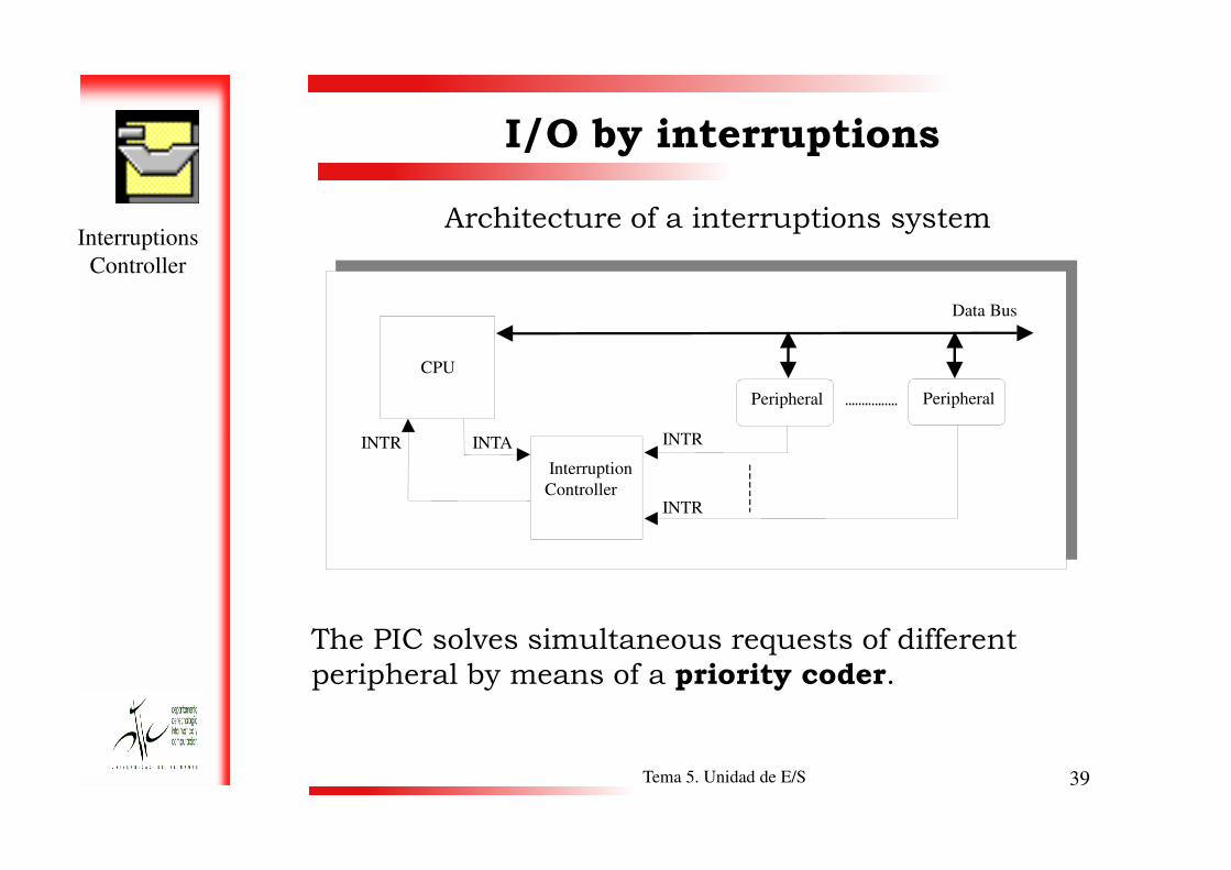
Architecture of a interruptions system
I/O by interruptions
CPU
Peripheral Peripheral
INTRINTR INTA
Data Bus
Tema 5. Unidad de E/S 39
The PIC solves simultaneous requests of different
peripheral by means of a priority coder.
INTR
INTR
INTR INTA
Interruption
Controller

Example
interruptions
controller
Interruptions Controller: Intel 8259A.
• It can handle up to
8 peripheral.
Cascade connection
up to 64 peripheral
•Interruptions
Nesting
I/O by interruptions
8259ASlave
IR0Peripheral
IR7Peripheral INT
Tema 5. Unidad de E/S 40
Nesting
• Priorities rotation.
•Interruptions
camouflage.
CPU8086
IR7Peripheral INT
8259AEsclavo
IR0Peripheral
IR7Peripheral INT
8259AMaster
IR0
IR7 INT INTR

ConceptThe two previous I/O techniques present/display two
disadvantages:
� The data transfer is limited by the speed whereupon the
CPU can verify and take care of a peripheral.
� The CPU is forced to manage the I/O transference.
When great amounts of data move, a more effective
I/O by DMA
Tema 5. Unidad de E/S 41
When great amounts of data move, a more effective
technique is needed more than the less possible CPU
takes part:
Data transfer by means of a controller of direct memory access
de datos mediante un controlador de acceso directo a memoria
(Direct Memory Access).

ControllerThe formed controller of DMA:
� Data registries.
� Address register: it stores the direction of the following
word that is going away to transmit (automatic
increase).
I/O by DMA
Tema 5. Unidad de E/S 42
� Registry accountant of words: it stores the number of
words that are to send (automatic increase). If it is
worth 0, the interruption signal is sent to the CPU
indicating to him that the transference has finalized.

DMA
Controller
Structure
I/O by DMA
Direction Bus
Data Bus
Tema 5. Unidad de E/S 43
Registry accountant
of words
Control
Logic
DMA request
(DMA REC)
Peripheral
Direction
registryData Registry
DMA recognition
(DMA ACK)
INTRReadingWriting
DMA
Controller
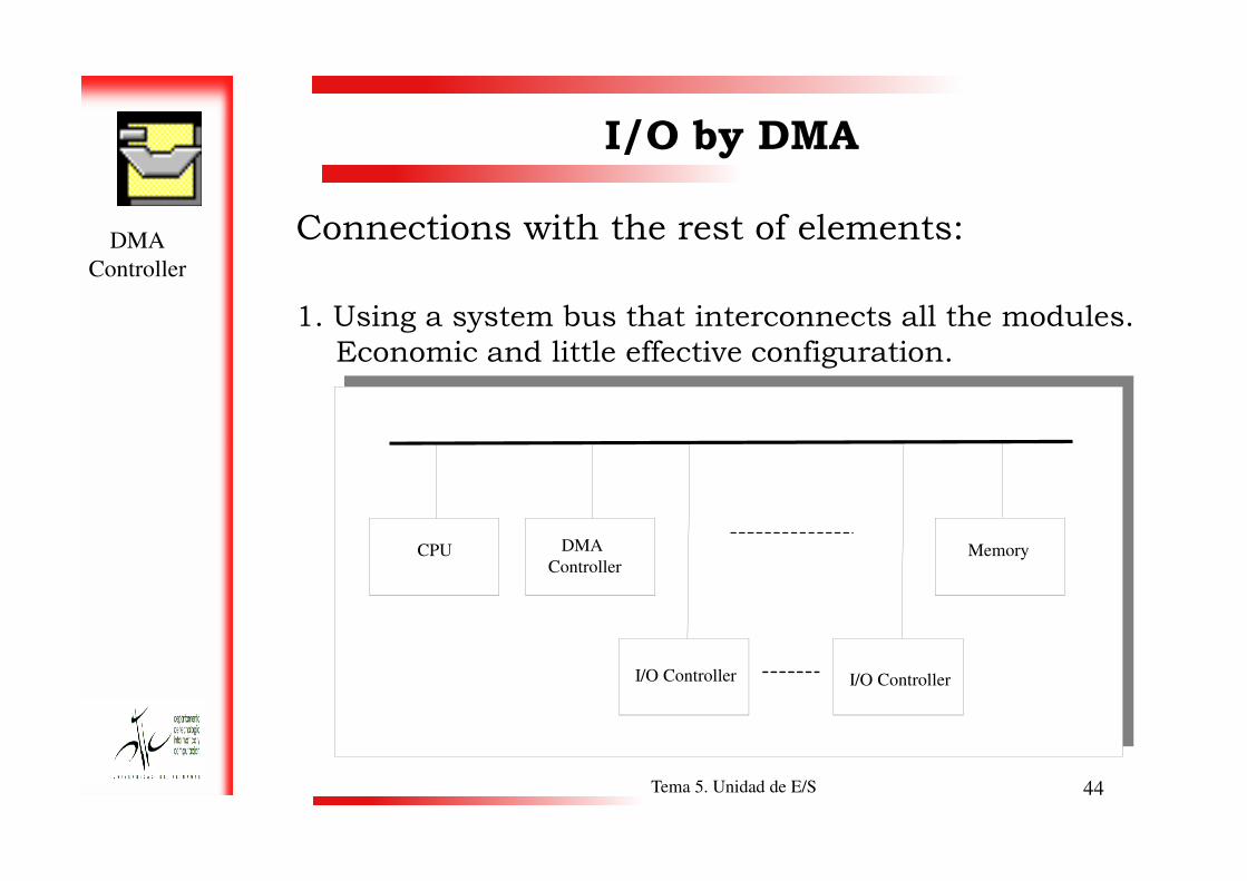
Connections with the rest of elements:
1. Using a system bus that interconnects all the modules.
Economic and little effective configuration.
I/O by DMA
Tema 5. Unidad de E/S 44
CPU DMA
Controller
I/O Controller
Memory
I/O Controller

DMA
Controller
2. Using a system bus that interconnects all the modules
except the ES controllers.
I/O by DMA
Tema 5. Unidad de E/S 45
CPU MemoryDMA
Controller
DMA
Controller
I/O Controller I/O Controller I/O Controller

DMA
Controller
3. Using a I/O bus that interconnects all the I/O
controllers to the DMA controller
I/O by DMA
CPU Memory
System Bus
DMA
Tema 5. Unidad de E/S 46
CPU Memory
I/O Bus
DMA
Controller
I/O Controller I/O Controller I/O Controller

Operation1. CPU sends: the peripheral direction, the operation type
(read/write), the position of beginning in memory and
the number of words that must read or write.
2. Now the CPU can make another task.
3. The DMA controller transfers directly, word to word,
the complete data block between peripheral and the
memory, without happening through the CPU.
I/O by DMA
Tema 5. Unidad de E/S 47
memory, without happening through the CPU.
4. When the transference finalizes the DMA controller
sends a interruption signal to the CPU to indicate to
him that it has already finished.
5. In this form the CPU participates solely in the
beginning and at the end of the transference.

InterruptionIn this type of transference, the DMA controller needs
to have the control of the bus to be able to transfer
data towards or from the memory.
I/O by DMA
Instruction cycle
Tema 5. Unidad de E/S 48
CPU cycle
DMA Breakthrough points
Search
Instruction
Decoding Search
operation
Execution Storage
result
Interruptions Breakthrough points

Data
Transference
Methods to data transfer:
1. By bursts. When the DMA takes the bus control does
not release it until to have transmitted the block of
data requested. With this method the greater speed of
transference is obtained but it is had to the inactive
CPU during relatively long periods.
I/O by DMA
Tema 5. Unidad de E/S 49
CPU cycle
I1 I2 I4I3 I5
I1 I2
Normal
Execution
Execution by bursts
Transference of the data block

Data
Transference
2. By cycle stealing. When the DMA takes the control of
the bus retains it during a single cycle. It transmits a
word and it releases the bus. The cycle stealing
reduces to the maximum to the transference speed
and the DMA interference controller on the activity of
the CPU.
I/O by DMA
Tema 5. Unidad de E/S 50
I1 I2 I4I3 I5
I1Cycle
Stealing Execution
DMAI2
DMAI3
DMAI4
DMA
CPU cycle
Normal
Execution

Data
Transference
3. Transparent DMA. The DMA steals cycle when the
CPU is not using the system bus. In certain phases of
the instruction execution the CPU does not use the
bus and is then when it can it uses the DMA. The
program execution of the CPU does not reduce its
speed, but concurrently a transference by DMA takes
place.
I/O by DMA
Tema 5. Unidad de E/S 51
place.
Free bus
Decoding Searchoperation
Executionresult
Search
Instruction
Storage

Data
Transference
4. Multiported memory. The CPU is connected to one of
the ports of the main memory and the rest of ports is
used for the DMA controllers and I/O controller.
The greater disadvantage of the multiported memory
I/O by DMA
Tema 5. Unidad de E/S 52
is its cost.

I/O Processor
ConceptThe I/O controllers have improved causing who behave
like a processor.
� The CPU causes that the I/O controller executes a I/O
program in memory.
� CPU causes that the I/O controller executes a I/O program in
memory.
The I/O controller takes and executes its instructions
Tema 5. Unidad de E/S 53
The I/O controller takes and executes its instructions
without CPU intervention. To this type of I/O controller is
denominated I/O channel.
� A later improvement of the I/O channels has been to
incorporate a local memory to them with which now they are
possible to be seen like computers.
With this architecture, a great set of I/O devices with the
minimum intervention of the CPU can be controlled. To this
type of I/O controller is denominated I/O processor.

TypesTypes of I/O processor:
� Selector channel. A selector channel controls several
high speed devices. At any moment of time it is
dedicated to the data transfer with only one of these
devices.
I/O Processor
Channel of data and directions
for main memory
Tema 5. Unidad de E/S 54
Peripheral Peripheral
for main memory
Signal of control
to the CPU
Peripheral
Selector
Channel
I/O Controller I/O Controller

Types� Channel multiplexor. A channel multiplexor can control of
simultaneous form operations of ES with multiple devices. For
peripheral of low speed, a multiplexor of bytes. For devices of high
speed, a multiplexor of blocks.
I/O Processor
Channel of data and directions
for main memory
Tema 5. Unidad de E/S 55
Multiplexor
Channel
Signal of control
to the CPUI/O Controller I/O Controller
Peripheral Peripheral Peripheral

I/O in MaNoTaS
I/O MaNoTaS� The interruptions system is formed by 32 software
numbered interruptions from the 0 to the 31.
Associated to the system of interruptions they are an
instruction set: INT, IRET, CLI and STI.
Tema 5. Unidad de E/S 56
� The I/O communication is made connecting the
peripheral one to one of the 256 I/O ports of 8
numbered bits from the 0 to the 255.
MaNoTaS has the instruction IN reading of a port and
instruction OUT to write.

I/O MaNoTaSExample:
; Program that reads 10 bytes of peripheralIN (1)
; and writes in the peripheralOUT (0)
mvi 0,C
bucle:
in 1
out 0
I/O in MaNoTaS
Tema 5. Unidad de E/S 57
out 0
inr c
mov c,a
cpi 10
jz fin
jmp bucle
fin:
jmp [FFFFh]
Note: Before executing the program they must connect
the peripheral in the MaNoTaS simulator.


![[Run Reloaded] Innovación y liderazgo (Pablo C. García + Jorge Rodríguez)](https://img.pdfslide.us/doc/110x75/5561e9a6d8b42af10c8b502f/run-reloaded-innovacion-y-liderazgo-pablo-c-garcia-jorge-rodriguez.jpg)