Embed Size (px)
Citation preview
InstallationPlanning
UNITY
INOVA NMR Spectrometer Systems
Pub. No. 01-999038-00, Rev. B0501
\
Installation Planning
UNITY
INOVA
™
NMR Spectrometer Systems Pub. No. 01-999038-00, Rev. B0501
Revision history:A0398 – Changed Pub. No. (was 87-195322-00). Added actively shielded magnet data.A0498 – Added minor changes from installation report.A0598 – Added hinged components dimensions to Table 7, as requested by Sales.A0698 – Updated telephone numbers.A0898 – Corrected Performa XYZ power to 20 A, Changed LHE and LN for 800/63.A0399 – Updated magnet data, added new magnets.A0200 – Updated crate dimensions of 600/51; Added boomerang table size.B0401 – Updated magnet data (600/51 AS, 400/54 AS, 900/54), ECO 9123.B0501 – Added missing 500/51 and 600/51 data.
Technical contributors: Mark Stevenson, Mark Van Criekinge, Emil Johnson, Chris JonesTechnical writers: Dan Steele, Mike Miller
Copyright
2001 by Varian, Inc.3120 Hansen Way, Palo Alto, California 94304http://www.varianinc.comAll rights reserved. Printed in the United States.
The information in this document has been carefully checked and is believed to be entirely reliable. However, no responsibility is assumed for inaccuracies. Statements in this document are not intended to create any warranty, expressed or implied. Specifications and performance characteristics of the software described in this manual may be changed at any time without notice. Varian reserves the right to make changes in any products herein to improve reliability, function, or design. Varian does not assume any liability arising out of the application or use of any product or circuit described herein; neither does it convey any license under its patent rights nor the rights of others. Inclusion in this document does not imply that any particular feature is standard on the instrument.
UNIT
Y
INOVA
is a trademark of Varian, Inc. Sun and the Sun logo are trademarks of Sun Microsystems, Inc. SPARC and SPARCstation are trademarks of SPARC International. Tygon is a trademark of DuPont Company. Ethernet is a trademark of Xerox Corporation. Oxford is a registered trademark of Oxford Instruments, Ltd. Other product names are trademarks or registered trademarks of their respective holders.
01-999038-00 B0501
UNITY
INOVA Installation Planning
3
Table of Contents
SAFETY PRECAUTIONS .................................................................................... 9
Introduction ...................................................................................................... 13
Chapter 1. Site Selection and System Delivery ............................................ 15
1.1 Installation Planning Process .............................................................................. 151.2 Site Selection ...................................................................................................... 161.3 Transport Route and System Shipping Dimensions ........................................... 171.4 System Shipment ................................................................................................ 18
Selecting a Local Shipping Company ......................................................... 19Postdelivery Inspection ............................................................................... 19
Chapter 2. Installation Site Requirements .................................................... 21
2.1 Accessibility of Site ............................................................................................ 212.2 Site Size .............................................................................................................. 212.3 Ceiling Height Requirements ............................................................................. 242.4 Structural Strength of Floor ................................................................................ 24
Magnet Weight Distribution, With No Antivibration System ..................... 25Magnet Weight Distribution, With Antivibration System ........................... 25
2.5 Floor Vibration Level Requirements .................................................................. 262.6 Magnet Support Requirement ............................................................................. 272.7 Magnetic Environment ....................................................................................... 272.8 Ventilation ........................................................................................................... 302.9 Ambient Temperature and Humidity .................................................................. 302.10 Radio-Frequency Environment ......................................................................... 31
Radio-Frequency Interference .................................................................... 31Radio-Frequency Emissions from Varian NMR Equipment ....................... 32
2.11 Helium and Nitrogen Refill Volumes and Intervals .......................................... 33
Chapter 3. Site Preparation ............................................................................ 35
3.1 Line Voltage Variation ........................................................................................ 353.2 Uninterrupted Power Supply .............................................................................. 363.3 Electrical Outlets ................................................................................................ 363.4 Separate Air Sources for System Options .......................................................... 383.5 Compressed Air Supply ...................................................................................... 393.6 AC Power and Air Conditioning ......................................................................... 403.7 Compressed Nitrogen Gas .................................................................................. 403.8 Telephone and Internet Access ........................................................................... 40
Table of Contents
4
UNITY
INOVA Installation Planning 01-999038-00 B0501
3.9 Electrostatic Discharges ..................................................................................... 413.10 Sun Workstation Preparation ............................................................................ 42
Magnetic Field Considerations ................................................................... 42Sun Workstations ........................................................................................ 42Sun Peripherals ........................................................................................... 42Solaris Media .............................................................................................. 43Solaris Installation ...................................................................................... 43Sun Documentation ..................................................................................... 43Sun Workstation Preparation Checklist ...................................................... 44Configuration and Peripherals .................................................................... 44Collecting System and Network Information ............................................. 44
.................................................................................................................... 46
Chapter 4. Installation Supplies..................................................................... 47
4.1 Required Installation Supplies and Equipment .................................................. 47Liquid Helium Supply ................................................................................ 48Liquid Nitrogen Supply .............................................................................. 49Helium Gas Supply ..................................................................................... 49Nitrogen Gas Supply for Magnet Installation ............................................. 49Face Mask and Thermal Gloves .................................................................. 50Heat Gun ..................................................................................................... 50Nonferromagnetic Ladder ........................................................................... 50Hoist ............................................................................................................ 50Isopropyl Alcohol and Acetone Solvents .................................................... 50
4.2 Recommended Installation Supplies and Equipment ......................................... 51Cryogenic Equipment Rack ........................................................................ 51Electrical Power Surge Protector ............................................................... 51Monitor Degaussing Coil ........................................................................... 51
4.3 LC-NMR Equipment, Supplies, and Solvents .................................................... 51
Chapter 5. Stray Magnetic Fields................................................................... 53
5.1 Safety Hazards of Strong Magnetic Fields ......................................................... 53Pacemakers ................................................................................................. 53Magnetic Field Exposure ............................................................................ 54
5.2 Stray Field Plots ................................................................................................. 555.3 Posting Requirements for Magnetic Field Warning Signs ................................. 67
Warning Signs ............................................................................................. 67
Chapter 6. System Cable Lengths and Room Layouts ................................ 69
6.1 System Cable Lengths ........................................................................................ 69RF Cable Harness Between the Magnet and Console ................................ 69Ethernet Cable Between Console and Host Computer ............................... 70Cable Lengths for Systems With Ultra•nmr™ Shims ................................ 70
6.2 NMR Room Layouts .......................................................................................... 72Minimum Space for a 300/54 System Without Options ............................. 72Standard Space for a 300/54 System Without Options ............................... 73
Table of Contents
01-999038-00 B0501
UNITY
INOVA Installation Planning
5
Recommended Space for a 300/54 System With Autosampler .................. 74Minimum Space for a 300/89 System With Solids and Microimaging ...... 75Standard Space for a 400/54 or 300/89 System Without Options .............. 76Standard Space for a 400/54 or 500/51 System With Options ................... 77Minimum Space for a 600/51 System ......................................................... 78LC-NMR Minimum Room Layout ............................................................. 79LC-NMR Suggested Room Layout 1 ......................................................... 80LC-NMR Suggested Room Layout 2 ......................................................... 81
UNITY
INOVA
Illustrations for Room Layout ................................................. 82Blank Grid for Room Layout ...................................................................... 83
Index.................................................................................................................. 85
6
UNITY
INOVA Installation Planning 01-999038-00 B0501
List of Figures
Figure 1.
UNITY
INOVA
Cabinet and Oxford Magnet ....................................................................... 13
Figure 2.
Plan Views of Floor Contact Points of Magnet Stands .................................................. 25
Figure 3.
Platform Antivibration System Leg Placements and Sizes ........................................... 26
Figure 4.
Magnet Leg Antivibration Systems Leg Placement and Sizes ...................................... 26
Figure 5.
Typical Vertical Stray Fields for High-Field Magnets ................................................... 29
Figure 6.
Internal Wiring of Gradient Cabinet .............................................................................. 38
Figure 7.
Stray Field Plots for 800/63 Magnets ............................................................................ 65
Figure 8.
10-Gauss Warning Sign ................................................................................................. 68
Figure 9.
5-Gauss Warning Sign ................................................................................................... 68
Figure 10.
Magnet Area Danger Sign ........................................................................................... 68
Figure 11.
Cable Lengths for 200–500-MHz Systems without Options ...................................... 69
Figure 12.
Cable Lengths for High-Field Systems and Systems with Options ............................ 70
Figure 13.
Cable Lengths for Systems with Ultra•nmr Shims ...................................................... 71

01-999038-00 B0501
UNITY
INOVA Installation Planning
7
List of Tables
Table 1.
Magnet Dimensions as Shipped with Crate and Pallet .................................................... 17
Table 2.
Cabinet Dimensions as Shipped, with Crate and Pallet .................................................. 18
Table 3.
System Accessories Dimensions as Shipped with Crates and Pallets as Appropriate ..... 18
Table 4.
UNITY
INOVA
Cabinets Dimensions and Weights ............................................................... 22
Table 5.
Magnet Dimensions with Stand or Legs Attached ......................................................... 22
Table 6.
System Accessories Dimensions and Weights ............................................................... 23
Table 7.
Ceiling Minimum Height ................................................................................................ 24
Table 8.
Interaction Between a Magnetic Field and Common Objects ......................................... 28
Table 9.
Liquid Helium Displacement for Room Ventilation Considerations .............................. 30
Table 10.
Ambient Temperature and Relative Humidity ............................................................... 31
Table 11.
Operating Frequencies for NMR Spectrometers .......................................................... 31
Table 12.
Operating Frequencies for Common Nuclei ................................................................. 31
Table 13.
Results of RF Emissions Tests on Varian NMR Equipment ........................................ 32
Table 14.
IEEE/ANSI C95.1–1991 Standard for RF Radiation Levels ........................................ 33
Table 15.
Helium and Nitrogen Refill Intervals and Volumes ....................................................... 34
Table 16.
Electrical Outlets/Circuits Requirements ...................................................................... 36
Table 17.
Models of Techron Gradient Amplifiers ........................................................................ 38
Table 18.
Compressed Air Supply Source ..................................................................................... 39
Table 19.
Maximum Air Conditioning Requirements ................................................................... 41
Table 20.
Preinstallation Worksheet for Solaris ............................................................................ 45
Table 21.
Initial Onsite and Short Notice Liquid Helium Supplies .............................................. 48
Table 22.
Initial Onsite Liquid Nitrogen Supply ........................................................................... 49
Table 23.
Helium Gas Supply ....................................................................................................... 49
Table 24.
Stray Field Data for Oxford Magnets ............................................................................ 54
Table 25.
Stray Field Data for NMR Magnet Systems ................................................................. 55
Table 26.
Magnet Centerline to Floor ........................................................................................... 55

8
UNITY
INOVA Installation Planning 01-999038-00 B0501

01-999038-00 B0501
UNITY
INOVA Installation Planning
9
SAFETY PRECAUTIONS
The following warning and caution notices illustrate the style used in Varian manuals for safety precaution notices and explain when each type is used:
WARNING:
Warnings
are used when failure to observe instructions or precautions could result in injury or death to humans or animals, or significant property damage.
CAUTION:
Cautions
are used when failure to observe instructions could result in serious damage to equipment or loss of data.
Warning Notices
Observe the following precautions during installation, operation, maintenance, and repair of the instrument. Failure to comply with these warnings, or with specific warnings elsewhere in Varian manuals, violates safety standards of design, manufacture, and intended use of the instrument. Varian assumes no liability for customer failure to comply with these precautions.
WARNING:
Persons with implanted or attached medical devices such as pacemakers and prosthetic parts must remain outside the 5-gauss perimeter from the centerline of the magnet.
The superconducting magnet system generates strong magnetic fields that can affect operation of some cardiac pacemakers or harm implanted or attached devices such as prosthetic parts and metal blood vessel clips and clamps.
Pacemaker wearers should consult the user manual provided by the pacemaker manufacturer or contact the pacemaker manufacturer to determine the effect on a specific pacemaker. Pacemaker wearers should also always notify their physician and discuss the health risks of being in proximity to magnetic fields. Wearers of metal prosthetics and implants should contact their physician to determine if a danger exists.
Refer to the manuals supplied with the magnet for the size of a typical 5-gauss stray field. This gauss level should be checked after the magnet is installed.
WARNING:
Keep metal objects outside the 10-gauss perimeter from the centerline of the magnet.
The strong magnetic field surrounding the magnet attracts objects containing steel, iron, or other ferromagnetic materials, which includes most ordinary tools, electronic equipment, compressed gas cylinders, steel chairs, and steel carts. Unless restrained, such objects can suddenly fly towards the magnet, causing possible personal injury and extensive damage to the probe, dewar, and superconducting solenoid. The greater the mass of the object, the more the magnet attracts the object.
Only nonferromagnetic materials—plastics, aluminum, wood, nonmagnetic stainless steel, etc.—should be used in the area around the magnet. If an object is stuck to the magnet surface and cannot easily be removed by hand, contact Varian service for assistance.
SAFETY PRECAUTIONS
10
UNITY
INOVA Installation Planning 01-999038-00 B0501
Warning Notices (
continued
)
Refer to the manuals supplied with the magnet for the size of a typical 10-gauss stray field. This gauss level should be checked after the magnet is installed.
WARNING:
Only qualified maintenance personnel shall remove equipment covers or make internal adjustments.
Dangerous high voltages that can kill or injure exist inside the instrument. Before working inside a cabinet, turn off the main system power switch located on the back of the console.
WARNING:
Do not substitute parts or modify the instrument.
Any unauthorized modification could injure personnel or damage equipment and potentially terminate the warranty agreements and/or service contract. Written authorization approved by a Varian, Inc. product manager is required to implement any changes to the hardware of a Varian NMR spectrometer. Maintain safety features by referring system service to a Varian service office.
WARNING:
Do not operate in the presence of flammable gases or fumes.
Operation with flammable gases or fumes present creates the risk of injury or death from toxic fumes, explosion, or fire.
WARNING:
Leave area immediately in the event of a magnet quench.
If the magnet dewar should quench (sudden appearance of gasses from the top of the dewar), leave the area immediately. Sudden release of helium or nitrogen gases can rapidly displace oxygen in an enclosed space creating a possibility of asphyxiation. Do not return until the oxygen level returns to normal.
WARNING:
Avoid helium or nitrogen contact with any part of the body.
In contact with the body, helium and nitrogen can cause an injury similar to a burn. Never place your head over the helium and nitrogen exit tubes on top of the magnet. If helium or nitrogen contacts the body, seek immediate medical attention, especially if the skin is blistered or the eyes are affected.
WARNING:
Do not look down the upper barrel.
Unless the probe is removed from the magnet, never look down the upper barrel. You could be injured by the sample tube as it ejects pneumatically from the probe.
WARNING:
Do not exceed the boiling or freezing point of a sample during variable temperature experiments.
A sample tube subjected to a change in temperature can build up excessive pressure, which can break the sample tube glass and cause injury by flying glass and toxic materials. To avoid this hazard, establish the freezing and boiling point of a sample before doing a variable temperature experiment.
SAFETY PRECAUTIONS
01-999038-00 B0501
UNITY
INOVA Installation Planning
11
Warning Notices (
continued
)
WARNING:
Support the magnet and prevent it from tipping over.
The magnet dewar has a high center of gravity and could tip over in an earthquake or after being struck by a large object, injuring personnel and causing sudden, dangerous release of nitrogen and helium gasses from the dewar. Therefore, the magnet must be supported by at least one of two methods: with ropes suspended from the ceiling or with the antivibration legs bolted to the floor. Refer to the
Installation Planning Manual
for details.
WARNING:
Do not remove the relief valves on the vent tubes.
The relief valves prevent air from entering the nitrogen and helium vent tubes. Air that enters the magnet contains moisture that can freeze, causing blockage of the vent tubes and possibly extensive damage to the magnet. It could also cause a sudden dangerous release of nitrogen and helium gases from the dewar. Except when transferring nitrogen or helium, be certain that the relief valves are secured on the vent tubes.
WARNING:
On magnets with removable quench tubes, keep the tubes in place except during helium servicing.
On Varian 200- and 300-MHz 54-mm magnets only, the dewar includes removable helium vent tubes. If the magnet dewar should quench (sudden appearance of gases from the top of the dewar) and the vent tubes are not in place, the helium gas would be partially vented sideways, possibly injuring the skin and eyes of personnel beside the magnet. During helium servicing, when the tubes must be removed, follow carefully the instructions and safety precautions given in the manual supplied with the magnet.
Caution Notices
Observe the following precautions during installation, operation, maintenance, and repair of the instrument. Failure to comply with these cautions, or with specific cautions elsewhere in Varian manuals, violates safety standards of design, manufacture, and intended use of the instrument. Varian assumes no liability for customer failure to comply with these precautions.
CAUTION: Keep magnetic media, ATM and credit cards, and watches outside the 5-gauss perimeter from the centerline of the magnet.
The strong magnetic field surrounding a superconducting magnet can erase magnetic media such as floppy disks and tapes. The field can also damage the strip of magnetic media found on credit cards, automatic teller machine (ATM) cards, and similar plastic cards. Many wrist and pocket watches are also susceptible to damage from intense magnetism.
Refer to the manuals supplied with the magnet for the size of a typical 5-gauss stray field. This gauss level should be checked after the magnet is installed.
SAFETY PRECAUTIONS
12 UNITYINOVA Installation Planning 01-999038-00 B0501
Caution Notices (continued)
CAUTION: Keep the PCs, (including the LC STAR workstation) beyond the 5-gauss perimeter of the magnet.
Avoid equipment damage or data loss by keeping PCs (including the LC workstation PC) well away from the magnet. Generally, keep the PC beyond the 5-gauss perimeter of the magnet. Refer to the Installation Planning Guide for magnet field plots.
CAUTION: Check helium and nitrogen gas flowmeters daily.
Record the readings to establish the operating level. The readings will vary somewhat because of changes in barometric pressure from weather fronts. If the readings for either gas should change abruptly, contact qualified maintenance personnel. Failure to correct the cause of abnormal readings could result in extensive equipment damage.
CAUTION: Never operate solids high-power amplifiers with liquids probes.
On systems with solids high-power amplifiers, never operate the amplifiers with a liquids probe. The high power available from these amplifiers will destroy liquids probes. Use the appropriate high-power probe with the high-power amplifier.
CAUTION: Take electrostatic discharge (ESD) precautions to avoid damage to sensitive electronic components.
Wear grounded antistatic wristband or equivalent before touching any parts inside the doors and covers of the spectrometer system. Also, take ESD precautions when working near the exposed cable connectors on the back of the console.
Radio-Frequency Emission Regulations
The covers on the instrument form a barrier to radio-frequency (rf) energy. Removing any of the covers or modifying the instrument may lead to increased susceptibility to rf interference within the instrument and may increase the rf energy transmitted by the instrument in violation of regulations covering rf emissions. It is the operator’s responsibility to maintain the instrument in a condition that does not violate rf emission requirements.

01-999038-00 B0501 UNITYINOVA Installation Planning 13
Introduction
This guide assists in selecting and preparing a site to install a Varian UNITYINOVA NMR superconducting spectrometer system, including preparing the Sun workstation. Using the predelivery and postdelivery checklists provided and following the information presented should bring about a smooth transition from delivery to installation. Figure 1 illustrates a UNITYINOVA cabinet and an Oxford magnet.
This guide contains the following chapters:
• Chapter 1, “Site Selection and System Delivery,” describes how to plan for the installation of an NMR spectrometer. This chapter also discusses system delivery and provides a table of shipping dimensions for NMR components. Begin in this chapter.
• Chapter 2, “Installation Site Requirements,” lists the factors to consider when selecting the installation site.
• Chapter 3, “Site Preparation,” describes the many factors to consider—electrical, cooling, safety, supplies, and so forth—when preparing the installation site.
• Chapter 4, “Installation Supplies,” describes the supplies required and recommended for the system installation.
• Chapter 5, “Stray Magnetic Fields,” provides magnetic field safety data and shows stray field plots for each magnet system.
• Chapter 6, “System Cable Lengths and Room Layouts,”
• provides information for laying out the NMR room.
INOVAUNITY
Figure 1. UNITYINOVA Cabinet and Oxford Magnet

Introduction
14 UNITYINOVA Installation Planning 01-999038-00 B0501
Importance of CommunicationIn planning the system installation, good communications are essential between the customer, the facility planner or architect, and Varian on a frequent basis. Any questions or problems must be addressed immediately to avoid delays and additional costs. One person from the customer’s institution should be appointed to coordinate site planning and preparation. This person should represent all users of the system in dealing with Varian and the facility planner or architect.
Contacting VarianVarian’s staff of thoroughly trained service specialists throughout the world is your assurance of always receiving prompt attention.
For product sales and service information, contact one of the Varian sales offices:
• Argentina, Buenos Aires, (114) 783-5306
• Australia, Mulgrave, Victoria, (3) 9566-1138
• Austria, Vösendorf, (1) 699 96 69
• Belgium, Brussels, (2) 721 48 50
• Brazil, Sao Paulo, (11) 829-5444
• Canada, Ottawa, Ontario, (613) 260-0331
• China, Beijing, (10) 6846-3640
• Denmark, Herlev, (42) 84 6166
• France, Orsay, (1) 69 86 38 38
• Germany, Darmstadt, (6151) 70 30
• Italy, Milan, (2) 921351
• Japan, Tokyo, (3) 5232 1211
• Korea, Seoul, (2) 3452-2452
• Mexico, Mexico City, (5) 523-9465
• Netherlands, Houten, (30) 635 0909
• Norway, Oslo, (9) 86 74 70
• Russian Federation, Moscow, (95) 241-7014
• Spain, Madrid, (91) 472-7612
• Sweden, Solna, (8) 445 1601
• Switzerland, Zug, (41) 749 88 44
• Taiwan, Taipei, (2) 2698-9555
• United Kingdom, Walton-on-Thames, England (1932) 898 000
• United States, Palo Alto, California,Varian, Inc., NMR SystemsCustomer Sales Support, (650) 424-5145Service Support, Palo Alto, California, 1 (800) 356-4437E- mail: [email protected]
North American Service Manager9017 Mendenhall Ct., Ste D, Columbia, MD 21045(410) 381-7229
• Venezuela, Valencia (41) 257608
We at Varian will make every effort to ensure that the ownership of your new NMR spectrometer is a lasting and pleasurable experience.
01-999038-00 B0501 UNITYINOVA Installation Planning 15
Chapter 1. Site Selection and System Delivery
Sections in this chapter:
• 1.1 “Installation Planning Process” this page
• 1.2 “Site Selection” page 16
• 1.3 “Transport Route and System Shipping Dimensions” page 17
• 1.4 “System Shipment” page 18
Varian’s delivery responsibility ends at the Varian factory shipping dock or at the customer’s receiving dock, depending upon the type of insurance obtained by the customer. In either case, for 200- through 600-MHz magnets, the customer must provide a moving crew to move the shipping crates holding the system from the delivery truck (or storage location) to the installation site. For 750-MHz magnets and larger, Varian provides a moving crew.
1.1 Installation Planning ProcessUse the following steps to prepare for delivery of the system. Refer to the chapters in this guide for further details. Consult knowledgeable individuals, such as plant facilities personnel, for assistance in implementing these instructions.
1. Check the “SHIP BY” date on the Varian Order Acknowledgment form. Use this date as a target for completing installation preparations. If you anticipate any delays in site readiness and need to delay shipment, notify the factory at least 90 days in advance. Select the site for installing and operating the system. (Note: a site survey is standard with many UNITYINOVA spectrometer systems.)
Review the considerations described in Section 1.2 on page 16 and make sure the site conforms to the requirements listed in Chapter 2, “Installation Site Requirements,” on page 21.
2. Prepare the installation site, including electrical outlets, compressed air supply, and air conditioning as described in Chapter 3, “Site Preparation,” on page 35. Make any computer preparations required, also described in Chapter 3 .
3. Order supplies and equipment for installation and startup operation, as described in Chapter 4, “Installation Supplies,” on page 47.
4. Make arrangements for workers and equipment to move the system upon delivery to the installation site, as described in Section 1.4, “System Shipment,” on page 18.
5. Read carefully, sign, and mail to Varian the “Object Code License Form.” (Note that acceptance of the products on the Order Acknowledgment form constitutes acceptance of the terms stated in the Object Code License Form, whether the form is signed or not.)
Chapter 1. Site Selection and System Delivery
16 UNITYINOVA Installation Planning 01-999038-00 B0501
1.2 Site SelectionSite selection is the process of finding a location for the magnet providing the least interference with the building it occupies. The selection of an optimum site is determined almost entirely by the high magnetic fringe field of the system. The process of selection can be complex because of the interaction of the magnetic field with the surrounding environment. Chapter 2, “Installation Site Requirements,” describes in detail all the factors to consider when selecting a site.
1. Begin by looking for a site with a series of general requirements in mind. The placement of the magnet is the primary consideration:
• How will the field from the affect its neighbors?
• What will the building and its contents do to the quality of the magnet field?
• Can the system be delivered to the site?
2. The second requirement is access:
• Will the site limit public access in surrounding areas?
• Can magnetic storage media be taken to the area safely?
• Can cryogen transfers be made quickly and safely?
3. Finally, look at the area as a whole with the following considerations:
• Look for an area large enough to contain the magnet and as much of the 5-gauss line as possible. The area should have the minimum ceiling height described in Section 2.3, “Ceiling Height Requirements,” on page 24.
• When an acceptable space has been found, look for steel and iron in the immediate area. Consider the structural steel of the building, iron pipes, machinery, etc.
• Look in the near area for elevators, vehicular traffic, large transformers, and other large amounts of steel and iron.
• Consider the ability to control the movement of ferromagnetic objects, such as elevators, automobiles, or carts, within the magnetic field.
• Consider adequate access for the delivery of dewars containing liquid helium and nitrogen.
• Consider public access that might pass through the 5-gauss zone.
• Consider escape routes in case of emergency, including a magnet quench.
• Consider the location of sensitive electronic equipment that might be affected by the magnetic field. See Section 2.7, “Magnetic Environment,” on page 27 and Chapter 5, “Stray Magnetic Fields,” on page 53.
• For an exact definition of gauss line boundaries, refer to Section 5.2, “Stray Field Plots,” on page 55 for more information.
• Make sure you have enough ventilation in case of a quench. Refer to Section 2.8, “Ventilation,” on page 30.
1.3 Transport Route and System Shipping Dimensions
01-999038-00 B0501 UNITYINOVA Installation Planning 17
1.3 Transport Route and System Shipping DimensionsIf possible, move the crates in an upright position, with a forklift or hydraulic pallet mover, directly to the installation site.
CAUTION: Move the crates in an upright position. Do not drop or mishandle. The crates are packed with G-force and “tip-and-tell” indicators that record mishandling. Be especially careful about moving the magnet crate. If one or more crates cannot be moved into the installation site because of doorway clearance, leave the affected crates in a clean, safe, dry location. Do not open any crate except with direct instructions from an authorized service representative.
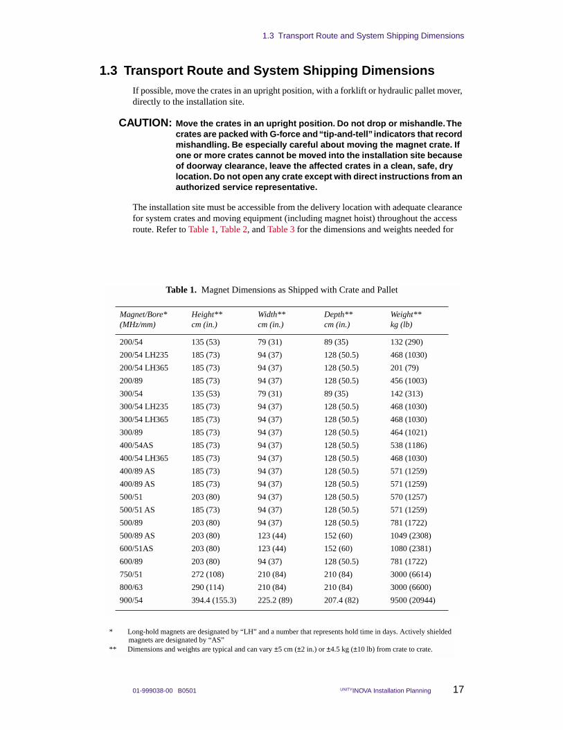
The installation site must be accessible from the delivery location with adequate clearance for system crates and moving equipment (including magnet hoist) throughout the access route. Refer to Table 1, Table 2, and Table 3 for the dimensions and weights needed for
Table 1. Magnet Dimensions as Shipped with Crate and Pallet
Magnet/Bore*(MHz/mm)
Height** cm (in.)
Width**cm (in.)
Depth**cm (in.)
Weight**kg (lb)
200/54 135 (53) 79 (31) 89 (35) 132 (290)
200/54 LH235 185 (73) 94 (37) 128 (50.5) 468 (1030)
200/54 LH365 185 (73) 94 (37) 128 (50.5) 201 (79)
200/89 185 (73) 94 (37) 128 (50.5) 456 (1003)
300/54 135 (53) 79 (31) 89 (35) 142 (313)
300/54 LH235 185 (73) 94 (37) 128 (50.5) 468 (1030)
300/54 LH365 185 (73) 94 (37) 128 (50.5) 468 (1030)
300/89 185 (73) 94 (37) 128 (50.5) 464 (1021)
400/54AS 185 (73) 94 (37) 128 (50.5) 538 (1186)
400/54 LH365 185 (73) 94 (37) 128 (50.5) 468 (1030)
400/89 AS 185 (73) 94 (37) 128 (50.5) 571 (1259)
400/89 AS 185 (73) 94 (37) 128 (50.5) 571 (1259)
500/51 203 (80) 94 (37) 128 (50.5) 570 (1257)
500/51 AS 185 (73) 94 (37) 128 (50.5) 571 (1259)
500/89 203 (80) 94 (37) 128 (50.5) 781 (1722)
500/89 AS 203 (80) 123 (44) 152 (60) 1049 (2308)
600/51AS 203 (80) 123 (44) 152 (60) 1080 (2381)
600/89 203 (80) 94 (37) 128 (50.5) 781 (1722)
750/51 272 (108) 210 (84) 210 (84) 3000 (6614)
800/63 290 (114) 210 (84) 210 (84) 3000 (6600)
900/54 394.4 (155.3) 225.2 (89) 207.4 (82) 9500 (20944)
* Long-hold magnets are designated by “LH” and a number that represents hold time in days. Actively shielded magnets are designated by “AS”
** Dimensions and weights are typical and can vary ±5 cm (±2 in.) or ±4.5 kg (±10 lb) from crate to crate.
Chapter 1. Site Selection and System Delivery
18 UNITYINOVA Installation Planning 01-999038-00 B0501
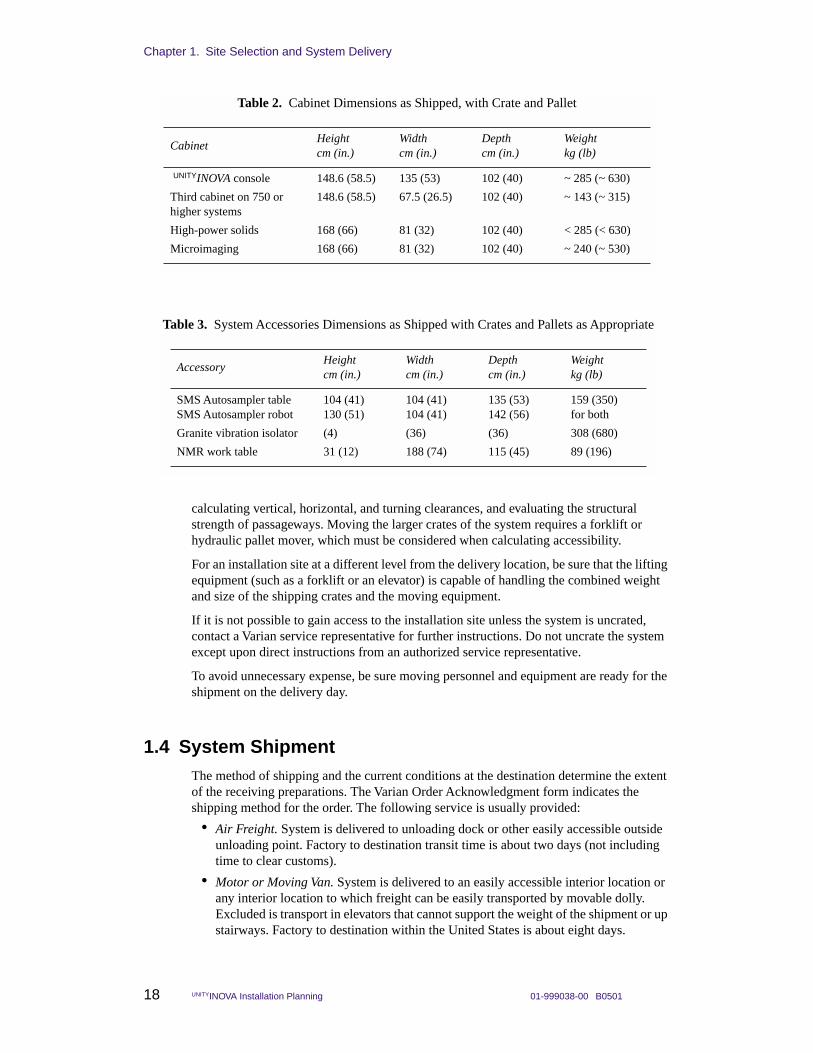
calculating vertical, horizontal, and turning clearances, and evaluating the structural strength of passageways. Moving the larger crates of the system requires a forklift or hydraulic pallet mover, which must be considered when calculating accessibility.
For an installation site at a different level from the delivery location, be sure that the lifting equipment (such as a forklift or an elevator) is capable of handling the combined weight and size of the shipping crates and the moving equipment.
If it is not possible to gain access to the installation site unless the system is uncrated, contact a Varian service representative for further instructions. Do not uncrate the system except upon direct instructions from an authorized service representative.
To avoid unnecessary expense, be sure moving personnel and equipment are ready for the shipment on the delivery day.
1.4 System ShipmentThe method of shipping and the current conditions at the destination determine the extent of the receiving preparations. The Varian Order Acknowledgment form indicates the shipping method for the order. The following service is usually provided:
• Air Freight. System is delivered to unloading dock or other easily accessible outside unloading point. Factory to destination transit time is about two days (not including time to clear customs).
• Motor or Moving Van. System is delivered to an easily accessible interior location or any interior location to which freight can be easily transported by movable dolly. Excluded is transport in elevators that cannot support the weight of the shipment or up stairways. Factory to destination within the United States is about eight days.
Table 2. Cabinet Dimensions as Shipped, with Crate and Pallet
CabinetHeightcm (in.)
Widthcm (in.)
Depthcm (in.)
Weightkg (lb)
UNITYINOVA console 148.6 (58.5) 135 (53) 102 (40) ~ 285 (~ 630)
Third cabinet on 750 or higher systems
148.6 (58.5) 67.5 (26.5) 102 (40) ~ 143 (~ 315)
High-power solids 168 (66) 81 (32) 102 (40) < 285 (< 630)
Microimaging 168 (66) 81 (32) 102 (40) ~ 240 (~ 530)
Table 3. System Accessories Dimensions as Shipped with Crates and Pallets as Appropriate
AccessoryHeightcm (in.)
Widthcm (in.)
Depthcm (in.)
Weightkg (lb)
SMS Autosampler table SMS Autosampler robot
104 (41)130 (51)
104 (41)104 (41)
135 (53)142 (56)
159 (350)for both
Granite vibration isolator (4) (36) (36) 308 (680)
NMR work table 31 (12) 188 (74) 115 (45) 89 (196)
1.4 System Shipment
01-999038-00 B0501 UNITYINOVA Installation Planning 19
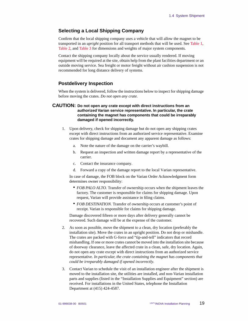
Selecting a Local Shipping Company
Confirm that the local shipping company uses a vehicle that will allow the magnet to be transported in an upright position for all transport methods that will be used. See Table 1, Table 2, and Table 3 for dimensions and weights of major system components.
Contact the shipping company locally about the service usually rendered. If moving equipment will be required at the site, obtain help from the plant facilities department or an outside moving service. Sea freight or motor freight without air cushion suspension is not recommended for long distance delivery of systems.
Postdelivery Inspection
When the system is delivered, follow the instructions below to inspect for shipping damage before moving the crates. Do not open any crate.
CAUTION: Do not open any crate except with direct instructions from an authorized Varian service representative. In particular, the crate containing the magnet has components that could be irreparably damaged if opened incorrectly.
1. Upon delivery, check for shipping damage but do not open any shipping crates except with direct instructions from an authorized service representative. Examine crates for shipping damage and document any apparent damage as follows:
a. Note the nature of the damage on the carrier’s waybill.
b. Request an inspection and written damage report by a representative of the carrier.
c. Contact the insurance company.
d. Forward a copy of the damage report to the local Varian representative.
In case of damage, the FOB block on the Varian Order Acknowledgment form determines owner responsibility:
• FOB PALO ALTO. Transfer of ownership occurs when the shipment leaves the factory. The customer is responsible for claims for shipping damage. Upon request, Varian will provide assistance in filing claims.
• FOB DESTINATION. Transfer of ownership occurs at customer’s point of receipt. Varian is responsible for claims for shipping damage.
Damage discovered fifteen or more days after delivery generally cannot be recovered. Such damage will be at the expense of the customer.
2. As soon as possible, move the shipment to a clean, dry location (preferably the installation site). Move the crates in an upright position. Do not drop or mishandle. The crates are packed with G-force and “tip-and-tell” indicators that record mishandling. If one or more crates cannot be moved into the installation site because of doorway clearance, leave the affected crate in a clean, safe, dry location. Again, do not open any crate except with direct instructions from an authorized service representative. In particular, the crate containing the magnet has components that could be irreparably damaged if opened incorrectly.
3. Contact Varian to schedule the visit of an installation engineer after the shipment is moved to the installation site, the utilities are installed, and non-Varian installation parts and supplies (listed in the “Installation Supplies and Equipment” section) are received. For installations in the United States, telephone the Installation Department at (415) 424-4587.

Chapter 1. Site Selection and System Delivery
20 UNITYINOVA Installation Planning 01-999038-00 B0501
01-999038-00 B0501 UNITYINOVA Installation Planning 21
Chapter 2. Installation Site Requirements
Sections in this chapter:
• 2.1 “Accessibility of Site” page 21
• 2.2 “Site Size” this page
• 2.3 “Ceiling Height Requirements” page 24
• 2.4 “Structural Strength of Floor” page 24
• 2.5 “Floor Vibration Level Requirements” page 26
• 2.6 “Magnet Support Requirement” page 27
• 2.8 “Ventilation” page 30
• 2.9 “Ambient Temperature and Humidity” page 30
• 2.10 “Radio-Frequency Environment” page 31
• 2.11 “Helium and Nitrogen Refill Volumes and Intervals” page 33
The UNITYINOVA NMR spectrometer has certain site requirements, which are described in this chapter. Factors to consider when selecting the installation site include:
• Site size and ceiling height
• Accessibility to the delivery location
• Floor rigidity and structural strength
• Magnetic and radio frequency environment
• Air ventilation, ambient temperature, and humidity
2.1 Accessibility of SiteThe site must provide adequate access for the routine delivery of supply dewars containing liquid helium and nitrogen. The site must also be accessible for system delivery, as described in Section 1.3, “Transport Route and System Shipping Dimensions,” on page 17
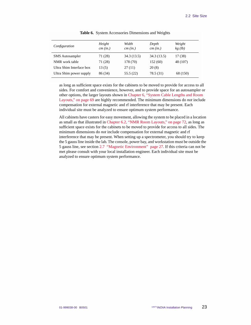
2.2 Site Size The site must be large enough to allow free access to all sides of the cabinet, magnet, and accessories for operation, maintenance, and cryogenic service. Table 4, Table 5, and Table 6 list the dimensions of the system components, and Chapter 6, “System Cable Lengths and Room Layouts,” on page 69, contains floor plans for the NMR laboratory area or room. The plans are suggestions and not specifications.
All cabinets have casters for easy movement, allowing the system to be placed in a location as small as that illustrated in the section “Minimum Space for 200/54 or 300/54 System Without Options,” in “Minimum Space for a 300/54 System Without Options” on page 72,
Chapter 2. Installation Site Requirements
22 UNITYINOVA Installation Planning 01-999038-00 B0501
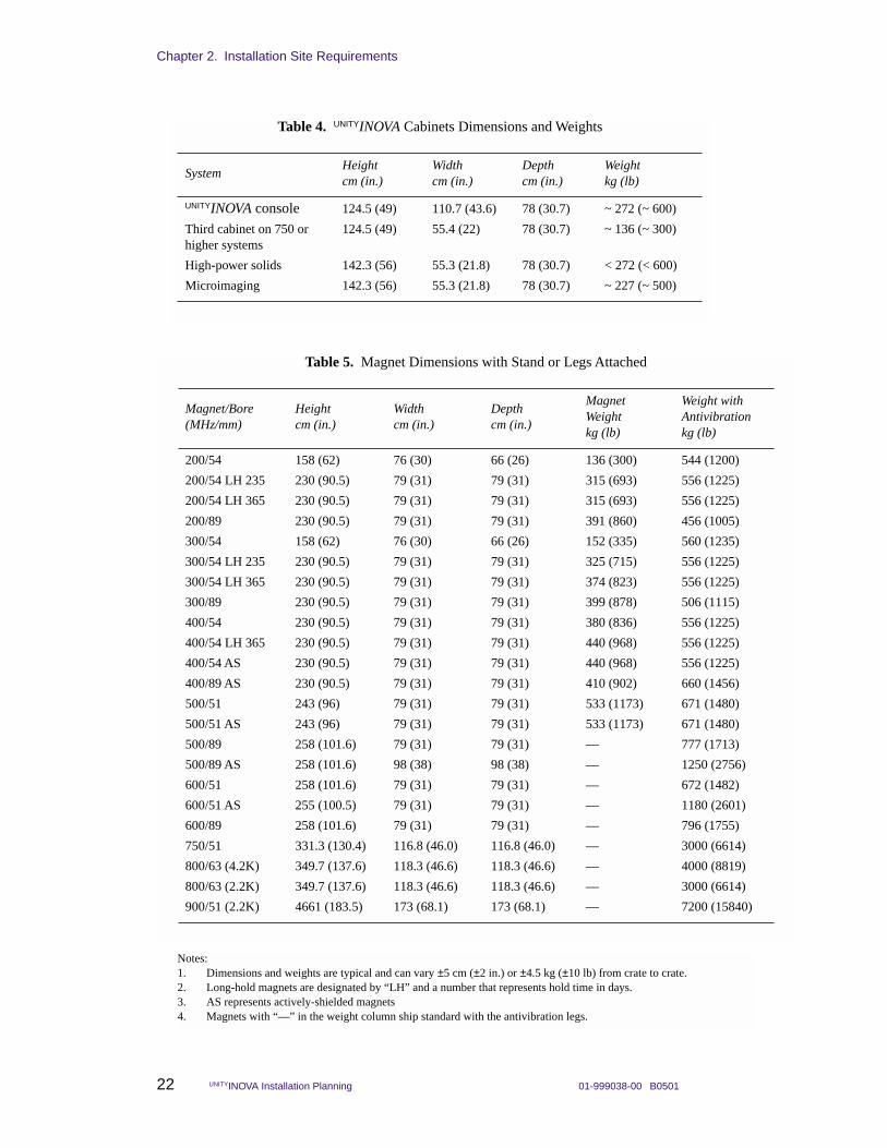
Table 4. UNITYINOVA Cabinets Dimensions and Weights
SystemHeightcm (in.)
Widthcm (in.)
Depthcm (in.)
Weightkg (lb)
UNITYINOVA console 124.5 (49) 110.7 (43.6) 78 (30.7) ~ 272 (~ 600)
Third cabinet on 750 or higher systems
124.5 (49) 55.4 (22) 78 (30.7) ~ 136 (~ 300)
High-power solids 142.3 (56) 55.3 (21.8) 78 (30.7) < 272 (< 600)
Microimaging 142.3 (56) 55.3 (21.8) 78 (30.7) ~ 227 (~ 500)
Notes:1. Dimensions and weights are typical and can vary ±5 cm (±2 in.) or ±4.5 kg (±10 lb) from crate to crate.2. Long-hold magnets are designated by “LH” and a number that represents hold time in days.3. AS represents actively-shielded magnets4. Magnets with “—” in the weight column ship standard with the antivibration legs.
Table 5. Magnet Dimensions with Stand or Legs Attached
Magnet/Bore(MHz/mm)
Heightcm (in.)
Widthcm (in.)
Depthcm (in.)
MagnetWeightkg (lb)
Weight with Antivibrationkg (lb)
200/54 158 (62) 76 (30) 66 (26) 136 (300) 544 (1200)
200/54 LH 235 230 (90.5) 79 (31) 79 (31) 315 (693) 556 (1225)
200/54 LH 365 230 (90.5) 79 (31) 79 (31) 315 (693) 556 (1225)
200/89 230 (90.5) 79 (31) 79 (31) 391 (860) 456 (1005)
300/54 158 (62) 76 (30) 66 (26) 152 (335) 560 (1235)
300/54 LH 235 230 (90.5) 79 (31) 79 (31) 325 (715) 556 (1225)
300/54 LH 365 230 (90.5) 79 (31) 79 (31) 374 (823) 556 (1225)
300/89 230 (90.5) 79 (31) 79 (31) 399 (878) 506 (1115)
400/54 230 (90.5) 79 (31) 79 (31) 380 (836) 556 (1225)
400/54 LH 365 230 (90.5) 79 (31) 79 (31) 440 (968) 556 (1225)
400/54 AS 230 (90.5) 79 (31) 79 (31) 440 (968) 556 (1225)
400/89 AS 230 (90.5) 79 (31) 79 (31) 410 (902) 660 (1456)
500/51 243 (96) 79 (31) 79 (31) 533 (1173) 671 (1480)
500/51 AS 243 (96) 79 (31) 79 (31) 533 (1173) 671 (1480)
500/89 258 (101.6) 79 (31) 79 (31) — 777 (1713)
500/89 AS 258 (101.6) 98 (38) 98 (38) — 1250 (2756)
600/51 258 (101.6) 79 (31) 79 (31) — 672 (1482)
600/51 AS 255 (100.5) 79 (31) 79 (31) — 1180 (2601)
600/89 258 (101.6) 79 (31) 79 (31) — 796 (1755)
750/51 331.3 (130.4) 116.8 (46.0) 116.8 (46.0) — 3000 (6614)
800/63 (4.2K) 349.7 (137.6) 118.3 (46.6) 118.3 (46.6) — 4000 (8819)
800/63 (2.2K) 349.7 (137.6) 118.3 (46.6) 118.3 (46.6) — 3000 (6614)
900/51 (2.2K) 4661 (183.5) 173 (68.1) 173 (68.1) — 7200 (15840)
2.2 Site Size
01-999038-00 B0501 UNITYINOVA Installation Planning 23
as long as sufficient space exists for the cabinets to be moved to provide for access to all sides. For comfort and convenience, however, and to provide space for an autosampler or other options, the larger layouts shown in Chapter 6, “System Cable Lengths and Room Layouts,” on page 69 are highly recommended. The minimum dimensions do not include compensation for external magnetic and rf interference that may be present. Each individual site must be analyzed to ensure optimum system performance.
All cabinets have casters for easy movement, allowing the system to be placed in a location as small as that illustrated in Chapter 6.2, “NMR Room Layouts,” on page 72, as long as sufficient space exists for the cabinets to be moved to provide for access to all sides. The minimum dimensions do not include compensation for external magnetic and rf interference that may be present. When setting up a spectrometer, you should try to keep the 5 gauss line inside the lab. The console, power bay, and workstation must be outside the 5 gauss line, see section 2.7 “Magnetic Environment” page 27. If this criteria can not be met please consult with your local installation engineer. Each individual site must be analyzed to ensure optimum system performance.
Table 6. System Accessories Dimensions and Weights
ConfigurationHeightcm (in.)
Widthcm (in.)
Depthcm (in.)
Weightkg (lb)
SMS Autosampler 71 (28) 34.3 (13.5) 34.3 (13.5) 17 (38)
NMR work table 71 (28) 178 (70) 152 (60) 48 (107)
Ultra Shim Interface box 13 (5) 27 (11) 20 (8)
Ultra Shim power supply 86 (34) 55.5 (22) 78.5 (31) 68 (150)
Chapter 2. Installation Site Requirements
24 UNITYINOVA Installation Planning 01-999038-00 B0501
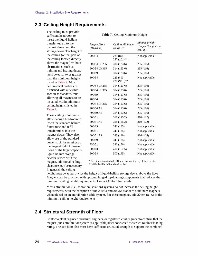
2.3 Ceiling Height RequirementsThe ceiling must provide sufficient headroom to insert the liquid-helium transfer tube into the magnet dewar and the storage dewar. The height of the ceiling (or that part of the ceiling located directly above the magnet) without obstructions, such as lighting and heating ducts, must be equal to or greater than the minimum heights listed in Table 7. Most helium-level probes are furnished with a flexible section as standard, thus allowing all magnets to be installed within minimum ceiling heights listed in Table 7.
These ceiling minimums allow enough headroom to insert the standard helium flutter tube and refill transfer tubes into the magnet dewar. They also allow use of the standard power stick for running up the magnet field. However, if one of the larger capacity liquid-helium storage dewars is used with the magnet, additional ceiling clearance may be necessary. In general, the ceiling height must be at least twice the height of liquid-helium storage dewar above the floor. Magnets can be provided with optional hinged top-loading components that reduces the minimum ceiling height requirements. Contact Oxford for details.
Most antivibration (i.e., vibration isolation) systems do not increase the ceiling height requirements, with the exception of the 200/54 and 300/54 standard aluminum magnets when placed on an antivibration table system. For these magnets, add 20 cm (8 in.) to the minimum ceiling height requirements.
2.4 Structural Strength of FloorContact a plant engineer, structural engineer, or registered civil engineer to confirm that the magnet (and antivibration system as applicable) does not exceed the structural floor loading rating. The site floor also must have sufficient structural strength to support the combined
* All dimensions include 110 mm to clear the top of the cryostat.**With flexible helium-level probe
Table 7. Ceiling Minimum Height
Magnet/Bore (MHz/mm)
Ceiling Minimumcm (in.)*
Minimum With Hinged Components cm (in.)
200/54 225 (89)257 (101)**
Not applicable
200/54 LH235 314 (123.6) 295 (116)
200/54 LH365 314 (123.6) 295 (116)
200/89 314 (123.6) 295 (116)
300/54 225 (89)237 (93.3)**
Not applicable
300/54 LH235 314 (123.6) 295 (116)
300/54 LH365 314 (123.6) 295 (116)
300/89 314 (123.6) 295 (116)
400/54 314 (123.6) 295 (116)
400/54 LH365 314 (123.6) 295 (116)
400/54 AS 314 (123.6) 295 (116)
400/89 AS 314 (123.6) 295 (116)
500/51 318 (125.2) 310 (122)
500/51 AS 318 (125.2) 310 (122)
500/89 343 (135) Not applicable
600/51 343 (135) Not applicable
600/51 AS 330 (130) 316 (124)
600/89 343 (135) Not applicable
750/51 380 (150) Not applicable
800/63 400 (157.5) Not applicable
900/54 500 (195) Not applicable
2.4 Structural Strength of Floor
01-999038-00 B0501 UNITYINOVA Installation Planning 25
weight of the entire spectrometer system and all moving equipment during installation. Table 4, Table 5, and Table 6.
Magnet Weight Distribution, With No Antivibration System
This section describes weight distribution for magnets without antivibration systems. The weights of the magnets, including stands, are given in Table 5.
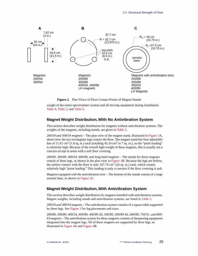
200/54 and 300/54 magnets – The plan view of the magnet stand, illustrated in Figure 2A, shows how the two rectangular legs contact the floor. The magnet stand has four adjustable feet of 11.61 cm2 (1.8 sq. in.) each (totalling 45.16 cm2 or 7 sq. in.), so the “point loading” is relatively high. Because of the overall light weight of these magnets, this is usually not a concern except in areas with a soft floor covering.
200/89, 300/89, 400/54, 400/89, and long-hold magnets – The stands for these magnets consist of three legs, as shown in the plan view in Figure 2B. Because the legs are hollow, the surface contact with the floor is only 167.74 cm2 (26 sq. in.) total, which creates relatively high “point loading.” This loading is only a concern if the floor covering is soft.
Magnets equipped with the antivibration tires – The bottom of the stands consist of a large annular base, as shown in Figure 2C.
Magnet Weight Distribution, With Antivibration System
This section describes weight distribution for magnets installed with antivibration systems. Magnet weights, including stands and antivibration systems, are listed in Table 5.
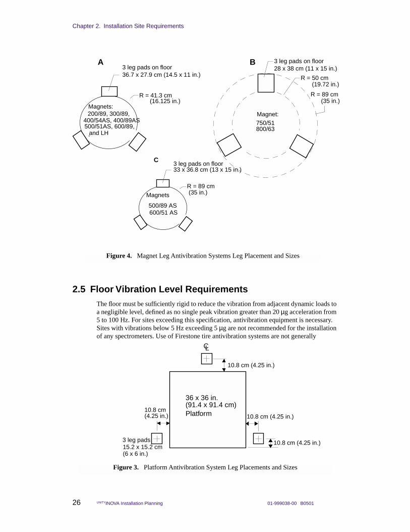
200/54 and 300/54 magnets – The antivibration system consists of a square table supported by three legs. See Figure 3 for leg placements and sizes.
200/89, 300/89, 400/54, 400/89, 400/89 AS, 500/89, 500/89 AS, 600/89, 750/51, and 800/63 magnets – The antivibration system for these magnets consists of dampening equipment integrated into the magnet legs. All of these magnets are supported by three legs, as illustrated in Figure 4A and Figure 4B.
(3 in.)
(24 in.)
(21.5 in.)
A B C
Ri = (10.75 in.)
Ro = (15.75 in.)
annularbase
R = 32.7 cm
leg pads
(6.5 in.)
Figure 2. Plan Views of Floor Contact Points of Magnet Stands
Magnets:200/89300/89
Magnets:200/54300/54
Magnets with antivibration tires:200/89 300/89
400/54, 400/89LH magnets
400/54
7.62 cm
61 cm
54.6 cm
(12.875 in.)
16.5 cm
O.D.
400/89
40 cm
27.3 cm
32.7 cm
LH Magnets
Chapter 2. Installation Site Requirements
26 UNITYINOVA Installation Planning 01-999038-00 B0501
2.5 Floor Vibration Level RequirementsThe floor must be sufficiently rigid to reduce the vibration from adjacent dynamic loads to a negligible level, defined as no single peak vibration greater than 20 µg acceleration from 5 to 100 Hz. For sites exceeding this specification, antivibration equipment is necessary. Sites with vibrations below 5 Hz exceeding 5 µg are not recommended for the installation of any spectrometers. Use of Firestone tire antivibration systems are not generally
CL
36 x 36 in.
Platform
10.8 cm (4.25 in.)
3 leg pads
(6 x 6 in.)
Figure 3. Platform Antivibration System Leg Placements and Sizes
(91.4 x 91.4 cm)
15.2 x 15.2 cm
10.8 cm (4.25 in.)
10.8 cm (4.25 in.)
10.8 cm (4.25 in.)
R = 41.3 cm
3 leg pads on floor36.7 x 27.9 cm (14.5 x 11 in.)
A B
Magnets:
Figure 4. Magnet Leg Antivibration Systems Leg Placement and Sizes
200/89, 300/89,
R = 50 cm
3 leg pads on floor28 x 38 cm (11 x 15 in.)
Magnet:750/51
R = 89 cm
800/63
(19.72 in.)
(35 in.)
,
(16.125 in.)
R = 89 cm
3 leg pads on floor33 x 36.8 cm (13 x 15 in.)
C
Magnets
500/89 AS
and LH
400/54AS, 400/89AS500/51AS, 600/89,
(35 in.)
600/51 AS

2.6 Magnet Support Requirement
01-999038-00 B0501 UNITYINOVA Installation Planning 27
recommended at sites with vibrations below 20 Hz or at any site with large vibrations in the horizontal direction. Ground floor or basement sites are generally preferred for systems because the natural resonant frequencies of most building structures are typically at low frequencies and horizontal in direction.
Measurements are made with an analyzer (Ono Sokki Model CF 200 field FFT analyzer, Hewlett-Packard Model 3561A signal analyzer, or equivalent) using 16 rms time averages and with a seismic accelerometer that has 10 V/g sensitivity (Wilcoxen Model 731 or equivalent).
2.6 Magnet Support RequirementThe magnet has a high center of gravity and could tip over during an earthquake or after being struck by a large object. Therefore, the magnet must be either supported either by ropes attached to the ceiling or by bolting the magnet legs to the floor. Magnet dimensions and weights are listed in Table 5. A structural engineer should be contacted to determine the best restraint method that meets local seismic requirement variations. If overhead ropes are used, the ceiling of the building should be evaluated for structural strength. The ropes should have a small amount of slack so that building vibrations are not transmitted to the magnet. These vibrations can cause artifacts to appear in the NMR spectra.
All systems with antivibration legs must be anchored to the floor. The antivibration system used incorporates the dampening mechanism as an integral part of the magnet leg. As a result the legs are not rigidly attached to the magnet. In order to work properly they must be firmly attached to the floor. This floor attachment also prevents the tipping of the leg in the case of an earthquake or being struck by a large object. Depending on the seismic requirement, the size of the magnet and the floor material, floor anchoring alone may not be adequate. A structural engineer should be contacted for recommendations. Anchoring to the floor is a standard procedure for many other types of equipment.
Varian expects that the customer’s plant or maintenance personnel can usually accomplish anchoring the leg. Varian supplies four 1/2-inch diameter anchor bolts for each leg. A minimum depth of 2.5 in is required for each bolt.
2.7 Magnetic Environment The site must have a minimum of environmental magnetic fields. Common sources of magnetic interference are fluctuating loads on adjacent power lines, radio or television transmissions, heavy-duty transformers, elevator motors, and similar electromagnetic devices. Allow a separation of at least 4.6 m (15 ft) between the magnet and other high-field electromagnets, elevators, or forklift trucks.
Similar separation distances must also be maintained between the magnet and anything that can cause a detrimental effect on the field homogeneity or the structural integrity of the magnet. Conditions that could interfere with the magnet include (but by no means limited to) a wall with metal sheathing or steel studding, a concrete support column with steel reinforcing bars, and a storage area containing steel dewars for cryogenic storage. Each site must be carefully analyzed to ensure optimum performance of the system. See Table 8 for examples of objects that affect or are affected by the magnetic field.
The CRT in color monitors needs to be degaussed in magnetic fields above 1 to 2 gauss. Above 5 gauss, color monitors may need additional shielding to prevent display distortion. Sun workstations and peripherals are also affected by the magnetic field; refer to Section
Chapter 2. Installation Site Requirements
28 UNITYINOVA Installation Planning 01-999038-00 B0501
3.10, “Sun Workstation Preparation,” on page 42 for a discussion of magnetic field considerations.
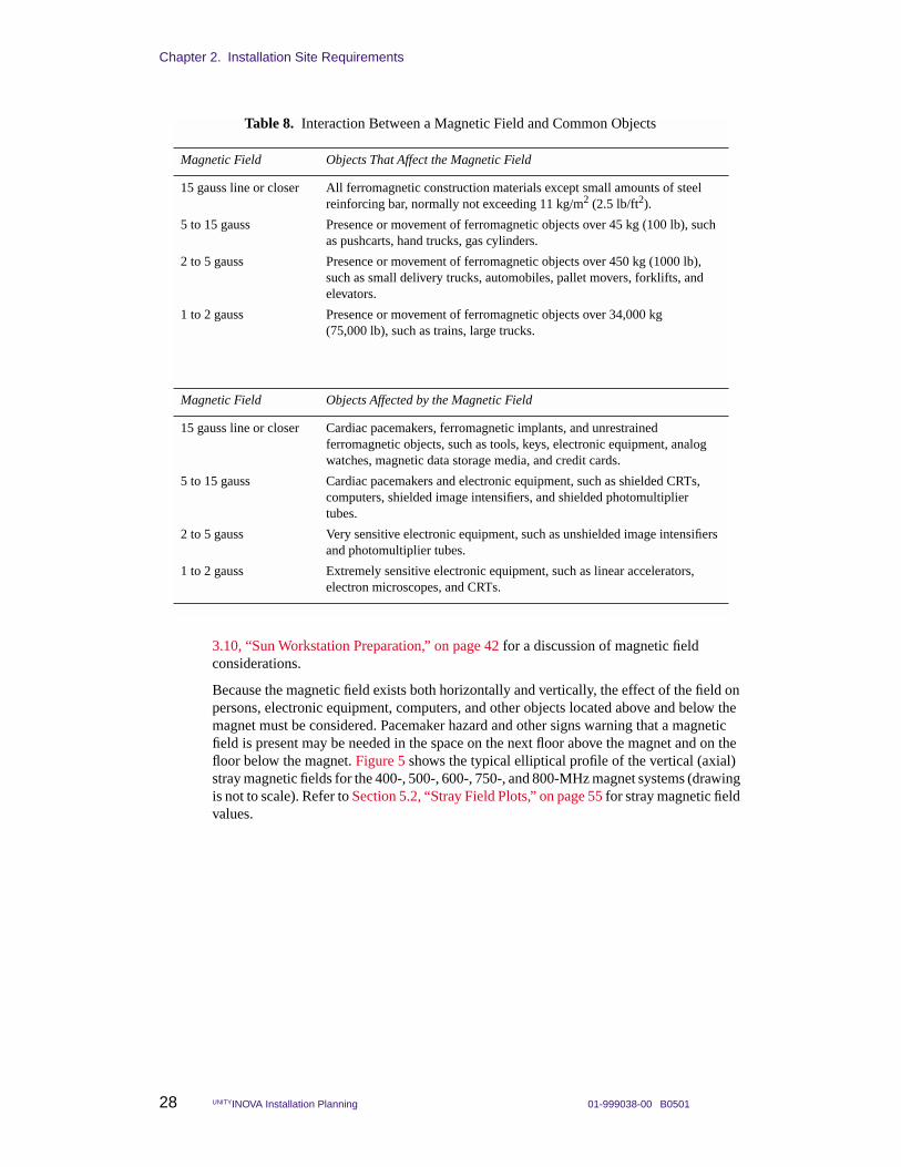
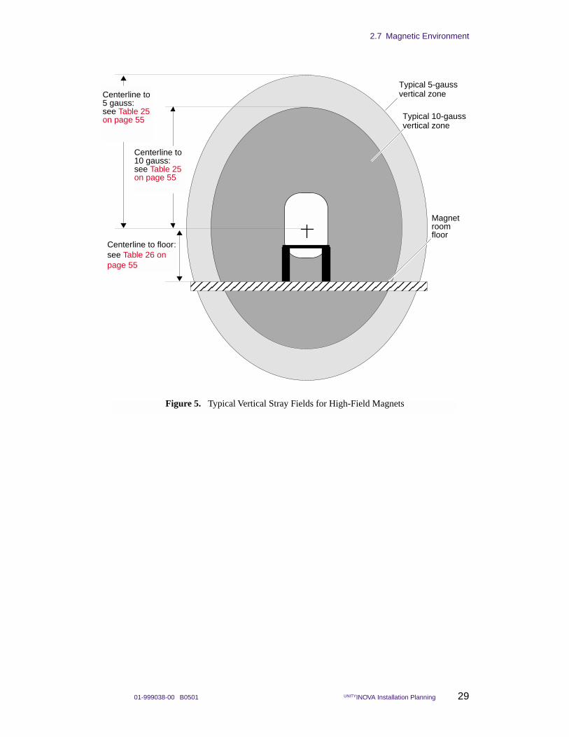
Because the magnetic field exists both horizontally and vertically, the effect of the field on persons, electronic equipment, computers, and other objects located above and below the magnet must be considered. Pacemaker hazard and other signs warning that a magnetic field is present may be needed in the space on the next floor above the magnet and on the floor below the magnet. Figure 5 shows the typical elliptical profile of the vertical (axial) stray magnetic fields for the 400-, 500-, 600-, 750-, and 800-MHz magnet systems (drawing is not to scale). Refer to Section 5.2, “Stray Field Plots,” on page 55 for stray magnetic field values.
Table 8. Interaction Between a Magnetic Field and Common Objects
Magnetic Field Objects That Affect the Magnetic Field
15 gauss line or closer All ferromagnetic construction materials except small amounts of steel reinforcing bar, normally not exceeding 11 kg/m2 (2.5 lb/ft2).
5 to 15 gauss Presence or movement of ferromagnetic objects over 45 kg (100 lb), such as pushcarts, hand trucks, gas cylinders.
2 to 5 gauss Presence or movement of ferromagnetic objects over 450 kg (1000 lb), such as small delivery trucks, automobiles, pallet movers, forklifts, and elevators.
1 to 2 gauss Presence or movement of ferromagnetic objects over 34,000 kg (75,000 lb), such as trains, large trucks.
Magnetic Field Objects Affected by the Magnetic Field
15 gauss line or closer Cardiac pacemakers, ferromagnetic implants, and unrestrained ferromagnetic objects, such as tools, keys, electronic equipment, analog watches, magnetic data storage media, and credit cards.
5 to 15 gauss Cardiac pacemakers and electronic equipment, such as shielded CRTs, computers, shielded image intensifiers, and shielded photomultiplier tubes.
2 to 5 gauss Very sensitive electronic equipment, such as unshielded image intensifiers and photomultiplier tubes.
1 to 2 gauss Extremely sensitive electronic equipment, such as linear accelerators, electron microscopes, and CRTs.
2.7 Magnetic Environment
01-999038-00 B0501 UNITYINOVA Installation Planning 29
Figure 5. Typical Vertical Stray Fields for High-Field Magnets
Typical 5-gauss vertical zone
Typical 10-gauss vertical zone
Centerline to floor:see Table 26 on page 55
Centerline to 5 gauss:see Table 25 on page 55
Centerline to 10 gauss:see Table 25 on page 55
Magnet room floor

Chapter 2. Installation Site Requirements
30 UNITYINOVA Installation Planning 01-999038-00 B0501
2.8 VentilationAir ventilation must be adequate to displace the liquid helium gas during a quench, especially when using any type of volatile liquid for variable temperature experiments. Consult with a safety engineer on this subject. Gaseous helium or nitrogen exhausted from the magnet will displace oxygen and cause asphyxiation if not properly ventilated. During a magnet quench, the evaporated helium is exhausted from the manifold by the pressure relief valves. The amount of gas depends on the amount of liquid helium held by the magnet at the time of the quench. Table 9 lists the approximate total amount of liquid helium for each magnet system. But it is unlikely that a magnet quench will boil off the total amount listed in the table. Also, remember that vented helium gas fills the room from the ceiling down, so place fans and ducts accordingly.
The expansion ratio of liquid helium at room temperature is about 740:1, which means that one liter of liquid helium expands to about 740 liters of helium gas.
• For fans rated in LPM (liters per minute), multiply the LHe maximum volume listed in Table 9 by 740 to get an idea of helium gas the fan should be capable of displacing.
• For fans rated in CFM (cubic feet per minute), multiply the LHe maximum volume listed in Table 9 by 26.13 (includes expansion ratio) to get an idea of the total amount of helium gas that the fan should be capable of displacing (e.g., a magnet that holds 30 liters of LHe will require a fan that can displace about 784 ft3 of helium gas).
2.9 Ambient Temperature and HumidityTable 10 lists the required ambient temperature ranges, temperature stability, and humidity levels for the site. For optimal performance, the ambient temperature around the magnet should not vary. Magnet homogeneity is optimized if the ambient temperature stability is maintained for the duration of an experiment and between shimming. Sunlight should never shine directly on the magnet or the area surrounding the magnet.
If necessary, install an air conditioning system to maintain the required conditions. Keep the air conditioning system operating continuously to stabilize the temperature and humidity surrounding the spectrometer system. The air flow from the room heating and cooling system must not blow on the magnet. Do not allow moisture to collect on, in, or around the system. At high altitudes (above 5000 ft), the cooling efficiency for the
Table 9. Liquid Helium Displacement for Room Ventilation Considerations
Magnet/Bore(MHz/mm)
LHe Maximum Volume(liters)
200/54 30
200/54 LH235 87
200/54 LH365 136
200/89 76
300/54 30
300/54 LH235 87
300/54 LH365 136
300/89 76
400/54 74
400/54 LH365 123
400/54 AS 123
400/89 AS 69
500/51 69
500/51 AS 130
500/89 130
600/51 130
600/51 AS 198
600/89 115
750/51 440
800/63 450
900/54 1350
2.10 Radio-Frequency Environment
01-999038-00 B0501 UNITYINOVA Installation Planning 31
electronics is lower. This can be compensated for by lowering the room temperature by one or two degrees from the room temperature specification.
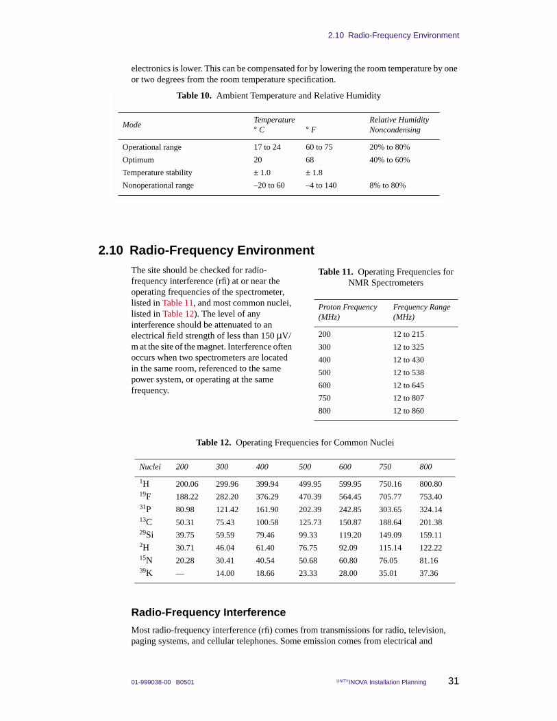
2.10 Radio-Frequency EnvironmentThe site should be checked for radio-frequency interference (rfi) at or near the operating frequencies of the spectrometer, listed in Table 11, and most common nuclei, listed in Table 12). The level of any interference should be attenuated to an electrical field strength of less than 150 µV/m at the site of the magnet. Interference often occurs when two spectrometers are located in the same room, referenced to the same power system, or operating at the same frequency.
Radio-Frequency Interference
Most radio-frequency interference (rfi) comes from transmissions for radio, television, paging systems, and cellular telephones. Some emission comes from electrical and
Table 10. Ambient Temperature and Relative Humidity
ModeTemperature Relative Humidity ° C ° F Noncondensing
Operational range 17 to 24 60 to 75 20% to 80%
Optimum 20 68 40% to 60%
Temperature stability ± 1.0 ± 1.8
Nonoperational range –20 to 60 –4 to 140 8% to 80%
Table 11. Operating Frequencies for NMR Spectrometers
Proton Frequency(MHz)
Frequency Range(MHz)
200 12 to 215
300 12 to 325
400 12 to 430
500 12 to 538
600 12 to 645
750 12 to 807
800 12 to 860
Table 12. Operating Frequencies for Common Nuclei
Nuclei 200 300 400 500 600 750 800
1H 200.06 299.96 399.94 499.95 599.95 750.16 800.8019F 188.22 282.20 376.29 470.39 564.45 705.77 753.4031P 80.98 121.42 161.90 202.39 242.85 303.65 324.1413C 50.31 75.43 100.58 125.73 150.87 188.64 201.3829Si 39.75 59.59 79.46 99.33 119.20 149.09 159.112H 30.71 46.04 61.40 76.75 92.09 115.14 122.2215N 20.28 30.41 40.54 50.68 60.80 76.05 81.1639K — 14.00 18.66 23.33 28.00 35.01 37.36
Chapter 2. Installation Site Requirements
32 UNITYINOVA Installation Planning 01-999038-00 B0501
electronic equipment in the immediate area. The horizontal NMR imaging system has a, shielded magnet bore and is not sensitive to average rfi levels. If the room level exceeds 10,000 µV/m, additional shielding may be required.
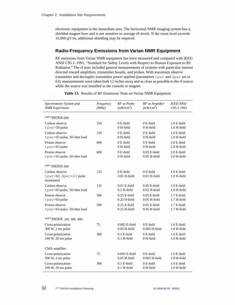
Radio-Frequency Emissions from Varian NMR Equipment
RF emissions from Varian NMR equipment has been measured and compared with IEEE/ANSI C95.1–1991, “Standard for Safety Levels with Respect to Human Exposure to RF Radiation.” The rf tests included general measurements of systems with particular interest directed toward amplifiers, transmitter boards, and probes. With maximum observe transmitter and decoupler transmitter power applied (parameters tpwr and dpwr set to 63), measurements were taken both 12 inches away and as close as possible to the rf source while the source was installed in the console or magnet.
Table 13. Results of RF Emissions Tests on Varian NMR Equipment
Spectrometer System and NMR Experiment
Frequency (MHz)
RF at Probe (mW/cm2)
RF at Amplifier (mW/cm2)
IEEE/ANSI C95.1-1991
UNITYINOVA 600
Carbon observetpwr=58 pulse
150 0 E-field0 H-field
0 E-field0 H-field
1.0 E-field1.0 H-field
Carbon observetpwr=63 pulse, 50-ohm load
150 0 E-field0 H-field
0 E-field0 H-field
1.0 E-field1.0 H-field
Proton observetpwr=63 pulse
600 0 E-field0 H-field
0 E-field0 H-field
2.0 E-field2.0 H-field
Proton observetpwr=63 pulse, 50-ohm load
600 0 E-field0 H-field
0.05 E-field0.05 H-field
2.0 E-field2.0 H-field
UNITYINOVA 500
Carbon observetpwr=63, dpwr=63 pulseterminated
125 0 E-field0.05 H-field
0 E-field0.01 H-field
1.0 E-field1.0 H-field
Carbon observetpwr=63 pulse, 50-ohm load
125 0.01 E-field0.2 H-field
0.05 E-field0.02 H-field
1.0 E-field1.0 H-field
Proton observetpwr=63 pulse
500 0.25 E-field0.25 H-field
0.05 E-field0.05 H-field
1.7 E-field1.7 H-field
Proton observetpwr=63 pulse, 50-ohm load
500 0.25 E-field0.25 H-field
0.05 E-field0.05 H-field
1.7 E-field1.7 H-field
UNITYINOVA 200, 300, 400
Cross-polarization300 W, 2 ms pulse
75 0.005 E-field0.05 H-field
0 E-field0.005 H-field
1.0 E-field1.8 H-field
Cross-polarization100 W, 20 ms pulse
300 0.1 E-field0.1 H-field
0 E-field0 H-field
1.0 E-field1.0 H-field
CMA amplifier
Cross-polarization300 W, 2 ms pulse
75 0.005 E-field0.05 H-field
0 E-field0.005 H-field
1.0 E-field1.8 H-field
Cross-polarization100 W, 20 ms pulse
300 0.1 E-field0.1 H-field
0 E-field0 H-field
1.0 E-field1.0 H-field
2.11 Helium and Nitrogen Refill Volumes and Intervals
01-999038-00 B0501 UNITYINOVA Installation Planning 33
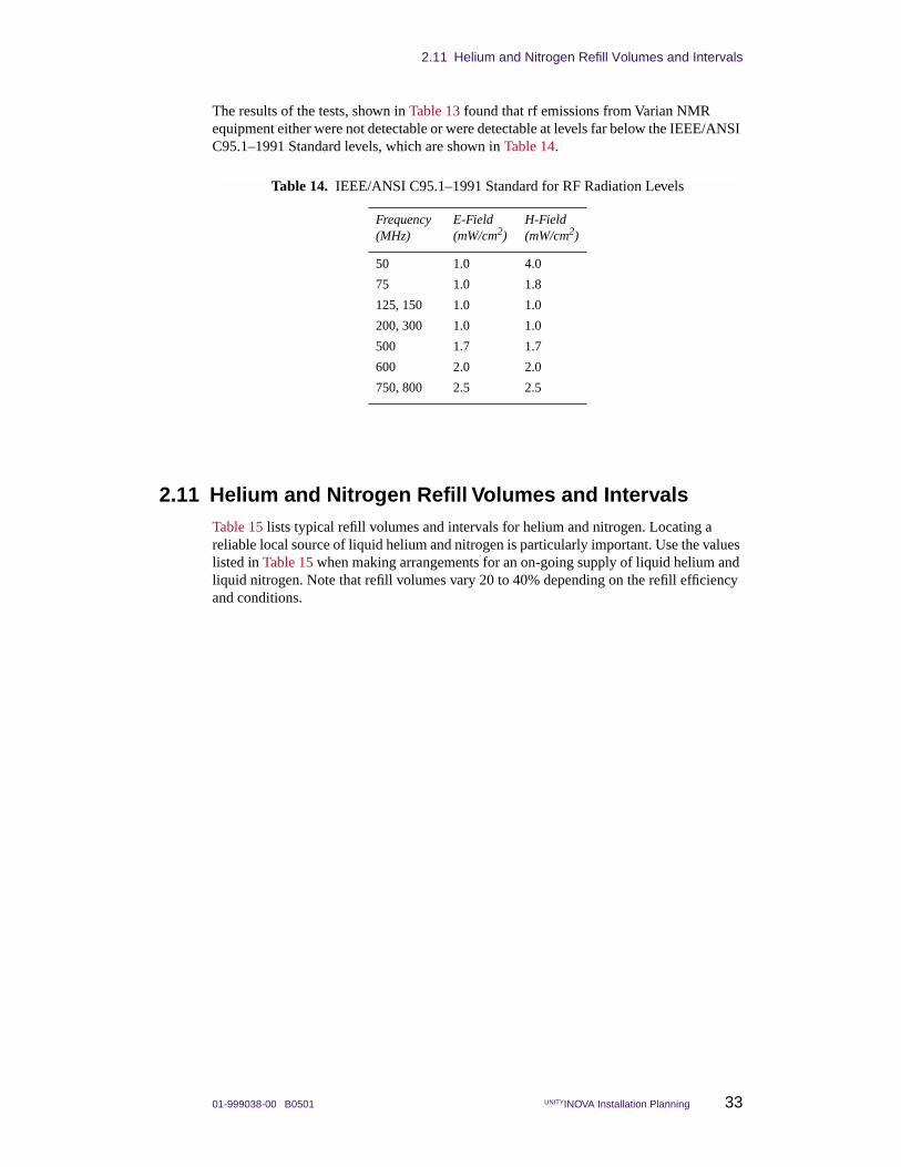
The results of the tests, shown in Table 13 found that rf emissions from Varian NMR equipment either were not detectable or were detectable at levels far below the IEEE/ANSI C95.1–1991 Standard levels, which are shown in Table 14.
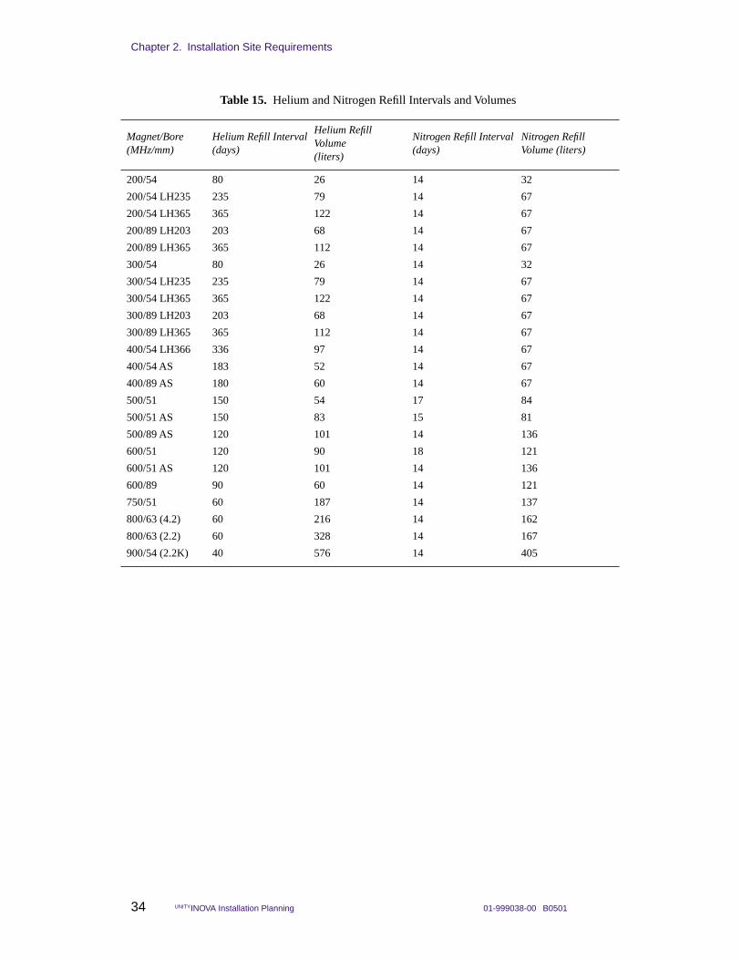
2.11 Helium and Nitrogen Refill Volumes and IntervalsTable 15 lists typical refill volumes and intervals for helium and nitrogen. Locating a reliable local source of liquid helium and nitrogen is particularly important. Use the values listed in Table 15 when making arrangements for an on-going supply of liquid helium and liquid nitrogen. Note that refill volumes vary 20 to 40% depending on the refill efficiency and conditions.
Table 14. IEEE/ANSI C95.1–1991 Standard for RF Radiation Levels
Frequency (MHz)
E-Field (mW/cm2)
H-Field (mW/cm2)
50 1.0 4.0
75 1.0 1.8
125, 150 1.0 1.0
200, 300 1.0 1.0
500 1.7 1.7
600 2.0 2.0
750, 800 2.5 2.5
Chapter 2. Installation Site Requirements
34 UNITYINOVA Installation Planning 01-999038-00 B0501
Table 15. Helium and Nitrogen Refill Intervals and Volumes
Magnet/Bore(MHz/mm)
Helium Refill Interval(days)
Helium Refill Volume(liters)
Nitrogen Refill Interval(days)
Nitrogen Refill Volume (liters)
200/54 80 26 14 32
200/54 LH235 235 79 14 67
200/54 LH365 365 122 14 67
200/89 LH203 203 68 14 67
200/89 LH365 365 112 14 67
300/54 80 26 14 32
300/54 LH235 235 79 14 67
300/54 LH365 365 122 14 67
300/89 LH203 203 68 14 67
300/89 LH365 365 112 14 67
400/54 LH366 336 97 14 67
400/54 AS 183 52 14 67
400/89 AS 180 60 14 67
500/51 150 54 17 84
500/51 AS 150 83 15 81
500/89 AS 120 101 14 136
600/51 120 90 18 121
600/51 AS 120 101 14 136
600/89 90 60 14 121
750/51 60 187 14 137
800/63 (4.2) 60 216 14 162
800/63 (2.2) 60 328 14 167
900/54 (2.2K) 40 576 14 405
01-999038-00 B0501 UNITYINOVA Installation Planning 35
Chapter 3. Site Preparation
Sections in this chapter:
• 3.1 “Line Voltage Variation” this page
• 3.2 “Uninterrupted Power Supply” page 36
• 3.3 “Electrical Outlets” page 36
• 3.4 “Separate Air Sources for System Options” page 38
• 3.5 “Compressed Air Supply” page 39
• 3.6 “AC Power and Air Conditioning” page 40
• 3.7 “Compressed Nitrogen Gas” page 40
• 3.8 “Telephone and Internet Access” page 40
• 3.9 “Electrostatic Discharges” page 41
• 3.10 “Sun Workstation Preparation” page 42
Verify the configuration with a Varian, Inc. representative before designing the room layout. Site preparation must conform with federal, state, and local codes, which take precedence over recommendations in this guide. Approval by a building inspector may be necessary.
3.1 Line Voltage Variation200-, 300-, 400-, 500-, and 600-MHz UNITYINOVA spectrometers require one line tap at 220 Vac, single phase. 750- and 800-MHz systems require two 220 Vac, single-phase lines. Current ratings for these taps are listed in Table 16.
Measure and record the ac line voltage for 48 hours using a suitable power line analyzer, such as the BMI Model 4800 or equivalent. Provide a copy for the Varian installation engineer. Requirements are the following:
• Long-term voltage variations (slow average) do not exceed 7% of nominal line tap voltages.
• Short-term voltage variations (sag or surge), with a duration between several milliseconds and several seconds, do not exceed 10% of nominal line tap voltage.
• Line transients (impulse), with a duration between 1 µs and 800 µs, do not exceed 50 V peak above or below nominal line tap voltage. These transients must be measured at the power plug with a load connected that draws the same power as the spectrometer.
• AC line frequency does not vary by more than +0.5 to –1.0 Hz.
Installing a line conditioner and regulator is strongly recommended. By providing protection against transients and improving line regulation, total system “up-time” improves and the electronic components within the system last longer. In many locations,
Chapter 3. Site Preparation
36 UNITYINOVA Installation Planning 01-999038-00 B0501
a good power conditioning system can pay for itself within a few years. Contact a local power consultant for suitable equipment in your area.
3.2 Uninterrupted Power SupplyIf your site experiences frequent and short (less than 10 minutes) power outages, you should consider installing an uninterrupted power supply (UPS). UPS systems are limited in how long they can supply power when house power is out. Consider the placement of a UPS when planning your lab. If you want to use a single UPS, it must have output for 220 Vac and 120 Vac and it must be installed such that both the NMR console and the host workstation can use it. If the UPS does not provide a 220 Vac output, use a step-up transformer to boost the 208 Vac output to 220 Vac. You can purchase an autotransformer from Varian (Part No. 01-901886-00). Solids systems require more than one transformer.
To determine the power rating for the UPS (in kW), refer to Table 19 on page 41 and add the values (kW) for the accessories with your system.
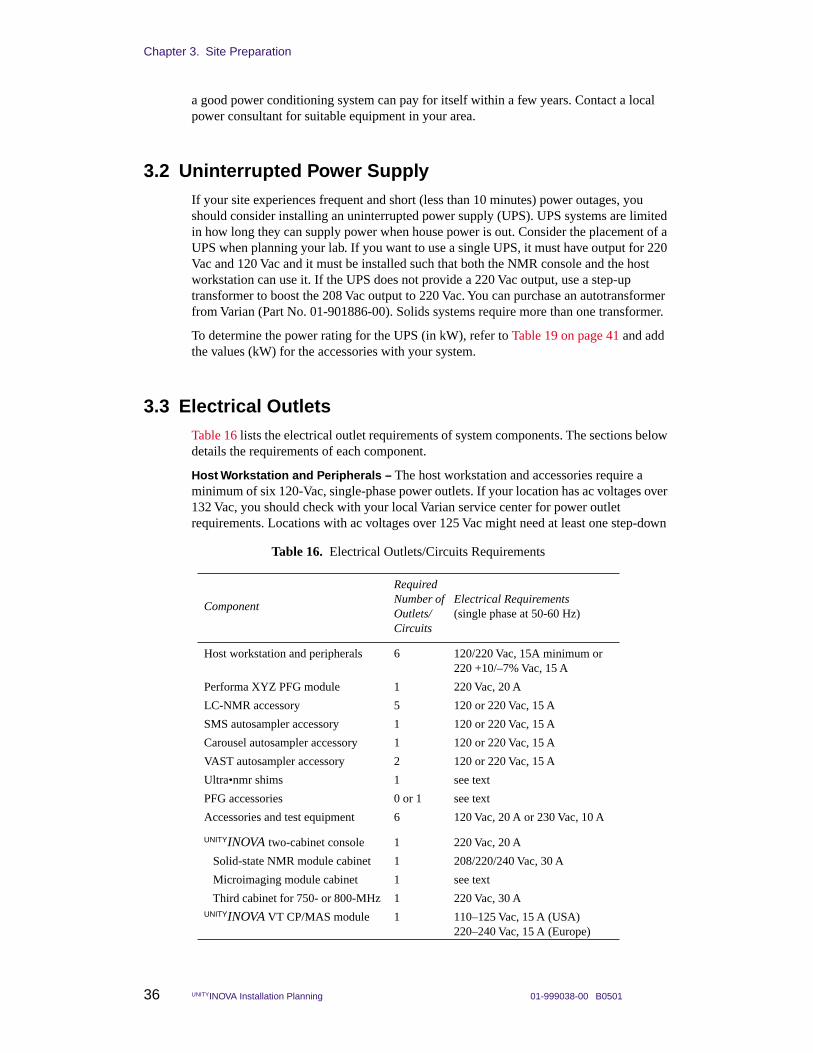
3.3 Electrical OutletsTable 16 lists the electrical outlet requirements of system components. The sections below details the requirements of each component.
Host Workstation and Peripherals – The host workstation and accessories require a minimum of six 120-Vac, single-phase power outlets. If your location has ac voltages over 132 Vac, you should check with your local Varian service center for power outlet requirements. Locations with ac voltages over 125 Vac might need at least one step-down
Table 16. Electrical Outlets/Circuits Requirements
Component
Required Number of Outlets/Circuits
Electrical Requirements(single phase at 50-60 Hz)
Host workstation and peripherals 6 120/220 Vac, 15A minimum or220 +10/–7% Vac, 15 A
Performa XYZ PFG module 1 220 Vac, 20 A
LC-NMR accessory 5 120 or 220 Vac, 15 A
SMS autosampler accessory 1 120 or 220 Vac, 15 A
Carousel autosampler accessory 1 120 or 220 Vac, 15 A
VAST autosampler accessory 2 120 or 220 Vac, 15 A
Ultra•nmr shims 1 see text
PFG accessories 0 or 1 see text
Accessories and test equipment 6 120 Vac, 20 A or 230 Vac, 10 A
UNITYINOVA two-cabinet console 1 220 Vac, 20 A
Solid-state NMR module cabinet 1 208/220/240 Vac, 30 A
Microimaging module cabinet 1 see text
Third cabinet for 750- or 800-MHz 1 220 Vac, 30 AUNITYINOVA VT CP/MAS module 1 110–125 Vac, 15 A (USA)
220–240 Vac, 15 A (Europe)
3.3 Electrical Outlets
01-999038-00 B0501 UNITYINOVA Installation Planning 37
transformer. The Host workstation and peripherals can operate in the Asian market 190 to 205 V range. To minimize ground loop interference, electrical outlets should all be on the same 20-A service. Surge protection is strongly recommended.
UNITYINOVA Two-Cabinet Console – The standard two-cabinet system requires a dedicated single-phase, continuous-duty 220 Vac (±7%), 50/60 Hz power line with 20-A minimum service (for up to 4 channels). Terminate this line within 3 m (10 ft) of the left side (looking from the rear) of the standard cabinet with a fused, quick-disconnect switch box or circuit breaker. Run a separate, insulated, low-resistance earth ground to the main electrical service entrance ground. A system with more than 4 channels requires a third cabinet, which is described in the next paragraph.
UNITYINOVA Third Cabinet for 750- or 800-MHz Systems – The 750/51 third cabinet requires a dedicated single-phase, continuous-duty 220 Vac (±7%), 50/60 Hz power line with 30-A minimum service. Terminate this line within 3 m (10 ft) of the left side (looking from the rear) of the standard cabinet with a fused, quick-disconnect switch box or circuit breaker. Run a separate, insulated, low-resistance earth ground to the main electrical service entrance ground.
UNITYINOVA Solid-State NMR Modules Cabinet – No extra electrical services are required for solids modules that do not require the third cabinet, such as CP/MAS. Solids modules that require the third cabinet, such as Wideline and CRAMPS/Multipulse, require an additional 208/220/240-Vac single-phase, 30-A dedicated line. A spectrometer system with complete liquids and solids capability (CP/MAS, Wideline, and CRAMPS/Multipulse) requires an electrical supply with one 220-Vac single-phase 20-A outlet and for the standard cabinet and one 208/220/240-Vac single-phase 30-A outlet for the high-power solids cabinet.
UNITYINOVA VT CP/MAS Module – A dedicated, single-phase, continuous-duty 50/60 Hz power line is required. The line should be 110 to 124 Vac, 15-A in the United States and 220 to 240 Vac, 15-A elsewhere. In addition, the customer must supply a 3-prong polarized plug compatible with the site voltage.
Performa XYZ PFG Module – The Performa XYZ PFG module includes a Performa XYZ gradient amplifier. This amplifier requires a single-phase, continuous-duty 208–220 Vac, 50/60 Hz power line with 20-A minimum service. Do not plug this amplifier into the power strip inside the NMR console because the power strip is not rated high enough and could cause problems.
Microimaging Module Cabinet – The gradient power cabinet of the microimaging module contains three Techron gradient amplifiers, a VME card cage, and a power distribution unit (PDU). Because the cabinet requires considerable electrical power, customers must provide a dedicated three-phase (3Ø) power line to a wall-mounted circuit breaker and wiring from the circuit breaker to the PDU. All wiring must conform to local electrical codes. For three-phase wiring configuration and requirements, check with your Varian representative. The 5-m (16.5-ft) 5-conductor cable to the PDU is supplied by Varian without connectors. Figure 6 shows the internal wiring of the gradient cabinet.
As shown in Table 17, Techron units come in four different models corresponding to the four input voltages. Varian recommends the 208 model for U.S. installations and the 380 model for most other installations (e.g., Europe). The customer must communicate the choice of power input voltage and mains frequency to Varian well in advance of the spectrometer shipping date so that the correct Techron models are included. Note that by using internal jumpers, the Techron 208 can be converted to the 240 model, and the 380 model can be converted to the 416 model.
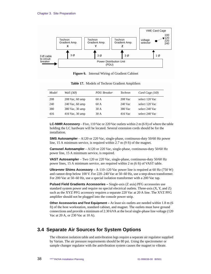
Chapter 3. Site Preparation
38 UNITYINOVA Installation Planning 01-999038-00 B0501
LC-NMR Accessory – Five, 110 Vac or 220 Vac outlets within 2 m (6 ft) of where the table holding the LC hardware will be located. Several extension cords should be for the installation.
SMS Autosampler – A120 or 220 Vac, single-phase, continuous-duty 50/60 Hz power line, 15 A minimum service, is required within 2.7 m (9 ft) of the magnet.
Carousel Autosampler – A120 or 220 Vac, single-phase, continuous-duty 50/60 Hz power line, 15 A minimum service, is required.
VAST Autosampler – Two 120 or 220 Vac, single-phase, continuous-duty 50/60 Hz power lines, 15 A minimum service, are required within 2 m (6 ft) of VAST table.
Ultra•nmr Shims Accessory – A 110–120 Vac power line is required at 60 Hz (750 W) and cannot drop below 100 V. For 220–240 Vac at 50–60 Hz, use a step-down transformer. For 200 Vac at 50–60 Hz, use a special isolation transformer with a 200 Vac tap.
Pulsed Field Gradients Accessories – Single-axis (Z axis) PFG accessories use standard system power and require no special electrical outlets. Three-axis (X, Y, and Z) such as the XYZ PFG accessory requires a separate 220 Vac at 20 A line. The XYZ PFG amplifier should not be plugged into the console power strip.
Other Accessories and Test Equipment – At least six outlets are needed within 1.8 m (6 ft) of the host workstation, standard cabinet, and magnet. The outlets must have ground connections and provide a minimum of 2.30 kVA at the local single-phase line voltage (120 Vac at 20 A, or 230 Vac at 10 A).
3.4 Separate Air Sources for System OptionsThe vibration isolation table and antivibration legs require a separate air regulator supplied by Varian. The air pressure requirements should be 80 psi. Using the spectrometer or sample changer regulator with the antivibration system causes the magnet to vibrate.
Figure 6. Internal Wiring of Gradient Cabinet
VME Card Cage
3 Ø cableto circuitbreaker Power Distribution Unit
(PDU)
1 Ø3 Ø3 Ø 3 Ø
TechronGradient Amp.
TechronGradient Amp.
TechronGradient Amp.
X Y Z
100120220240
voltageselector
Table 17. Models of Techron Gradient Amplifiers
Model Wall (3Ø) PDU Breaker Techron Card Cage (1Ø)
208 208 Vac, 60 amp 60 A 208 Vac select 120 Vac
240 240 Vac, 60 amp 60 A 240 Vac select 120 Vac
380 380 Vac, 30 amp 30 A 380 Vac select 240 Vac
416 416 Vac, 30 amp 30 A 416 Vac select 240 Vac
3.5 Compressed Air Supply
01-999038-00 B0501 UNITYINOVA Installation Planning 39
A system equipped with a vibration table or vibration isolators for the magnet also requires a separate air source and regulator. Bottled gas is not recommended for long-term operation.
The CP/MAS and CRAMPS solids options also require a separate regulated air source (or nitrogen gas for variable temperature operation) with 620 kPa (90 psig) pressure at the wall. Dewpoint should be –193°C (80 K) and oil removal greater than 99.5%. Filtration should be to 0.6 microns. The minimum flowrate at the wall is 80 lpm.
CAUTION: Contaminated air can cause extensive damage to the solids probe.
3.5 Compressed Air SupplyThe house compressed air supply must provide a source of air that is clean, dry, and free of contaminants, with a dew point of –40°C (–40°F) minimum. The dew point must be -60°C for the FTS coolers (preconditioning units) that are standard on 750-MHz and bigger magnets.
The source should include a reservoir and be capable of delivering the air pressures (in kilopascals or pounds-per-square-inch-gauge) and flow rates (in liters-per-minute or standard cubic-feet-per-hour) after filtering as given in Table 18.
Install a gate valve on the permanent outlet of the air supply line. The gate valve must be rated at least 860 kPa (125 psi or 9 kg/cm2). If the house line pressure is greater than this level, the valve must be rated at a level that exceeds the house pressure. Attach to the valve a minimum 1 cm (0.4 in.) pipe terminated with a 1/2-inch male NPT. Make the pipe long enough so that its termination fitting is within 4.5 m (15 ft) of the planned location of the magnet. A primary air regulator capable of ±2 psi is also required upstream from the gate valve.
Table 18. Compressed Air Supply Source
System Configuration Pressure Flow Rate
200, 300, or 400 system with liquids only, no options (air source needed for spin, probe cooling, VT, and eject):
Normal operation 310 kPa (45 psig) 27 LPM (57 SCFH)
During sample eject 310 kPa (45 psig) 45 LPM (95 SCFH)
500, 600, 750, or 800 system with liquids only, no options (air source needed for spin, probe/shim cooling, VT, and eject):
Normal operation 310 kPa (45 psig) 27 LPM (57 SCFH)
During sample eject 310 kPa (45 psig) 48 LPM (102 SCFH)
System with wideline module: Same as above
System with third/fourth rf channel: Same as above
System with CP/MAS or CRAMPS: 620 kPa (90 psig) 80 LPM (170 SCFH)
System with Doty probe: 414 kPa (60 psig) 50 LPM (106 SCFH)
System with microimaging module:
Gradient coil cooling 310 kPa (45 psig) 50 LPM (106 SCFH)
Probe cooling 310 kPa (45 psig) 20 LPM (42 SCFH)
System with antivibration systems: 585 kPa (80 psig) 4 LPM
Chapter 3. Site Preparation
40 UNITYINOVA Installation Planning 01-999038-00 B0501
In areas where humidity is high or where moisture in the air supply is a problem, consider installing a prefilter with an automatic drain to help prevent overload of the filter. In extreme cases, an air dryer assembly may be necessary.
The installation engineer will install on your air termination fitting a Varian-supplied assembly that includes a 0 to 690 kPa (0 to 100 psi) pressure gauge, a reduction valve, a standard 20 micron air filter, a coalescing oil filter (99.9 percent oil removal efficiency), and an air line to the magnet.
3.6 AC Power and Air ConditioningUse Table 19 to help determine maximum surge current, line conditioning, and air conditioning requirements. The surge current can be reduced by setting each rf amplifier to the off position using the rf amplifier switch on the rear panel, and then switching on the spectrometer power and turning on each rf amplifier separately.
A filter on the air conditioning unit intake and special air filtration is required in installations exposed to corrosive gases, salt air, or unusual dirt or dust conditions. The air conditioning system requires a power line separate from the spectrometer system.
3.7 Compressed Nitrogen GasDuring operation of the variable temperature accessory, a compressed nitrogen gas supply (from a cylinder or a fixed line) is required that is dry, oil-free, and magnetically clean (e.g., free of rust), with a dew point of –193°C (80 K). The flow and pressure rates through the regulators are the same as those listed for the compressed air supply.
3.8 Telephone and Internet AccessVarian recommends locating a regular voice telephone line near the host workstation. This telephone would enable the spectrometer operator to discuss the spectrometer system as it operates.
Varian also strongly recommends that Internet access be provided during and after system installation. By providing external access to the spectrometer, technical problems can be quickly analyzed by the engineering and scientific staff at Palo Alto. After the system is installed, applications-related questions can be answered in real time by Varian’s NMR applications people. As a matter of policy, Varian provides online support during installation and during the warranty period. If direct access to the Internet is not technically feasible, a high-quality analog telephone line can be used. Varian provides a high-speed modem during the system installation.
If internal security policies preclude ready modem or Internet access to the spectrometer, contact Varian’s installation department for a list of options that might satisfy security concerns.
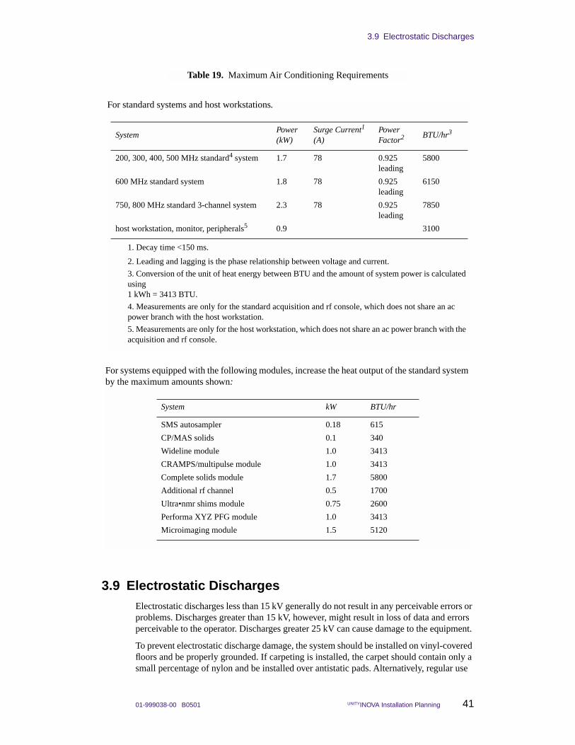
3.9 Electrostatic Discharges
01-999038-00 B0501 UNITYINOVA Installation Planning 41
3.9 Electrostatic DischargesElectrostatic discharges less than 15 kV generally do not result in any perceivable errors or problems. Discharges greater than 15 kV, however, might result in loss of data and errors perceivable to the operator. Discharges greater 25 kV can cause damage to the equipment.
To prevent electrostatic discharge damage, the system should be installed on vinyl-covered floors and be properly grounded. If carpeting is installed, the carpet should contain only a small percentage of nylon and be installed over antistatic pads. Alternatively, regular use
Table 19. Maximum Air Conditioning Requirements
For standard systems and host workstations.
SystemPower(kW)
Surge Current1 (A)
1. Decay time <150 ms.
Power Factor2
2. Leading and lagging is the phase relationship between voltage and current.
BTU/hr3
3. Conversion of the unit of heat energy between BTU and the amount of system power is calculated using 1 kWh = 3413 BTU.
200, 300, 400, 500 MHz standard4 system
4. Measurements are only for the standard acquisition and rf console, which does not share an ac power branch with the host workstation.
1.7 78 0.925leading
5800
600 MHz standard system 1.8 78 0.925leading
6150
750, 800 MHz standard 3-channel system 2.3 78 0.925leading
7850
host workstation, monitor, peripherals5
5. Measurements are only for the host workstation, which does not share an ac power branch with the acquisition and rf console.
0.9 3100
For systems equipped with the following modules, increase the heat output of the standard system by the maximum amounts shown:
System kW BTU/hr
SMS autosampler 0.18 615
CP/MAS solids 0.1 340
Wideline module 1.0 3413
CRAMPS/multipulse module 1.0 3413
Complete solids module 1.7 5800
Additional rf channel 0.5 1700
Ultra•nmr shims module 0.75 2600
Performa XYZ PFG module 1.0 3413
Microimaging module 1.5 5120
Chapter 3. Site Preparation
42 UNITYINOVA Installation Planning 01-999038-00 B0501
of a good quality antistatic spray can help considerably in alleviating the problem. Whenever a printed circuit board must be touched or handled, the person should wear grounded wrist straps.
CAUTION: Many components in the system contain highly sensitive electronic devices that must be protected from electrostatic discharges by proper floor coverings and grounding practices. A person walking across a nylon carpet or wearing synthetic fabrics can generate an electrostatic charge that can discharge to the next object that is touched. If this happens to be the system, the system components can be damaged. An overly dry atmosphere also tends to create an electrostatic charge. As with any system based on integrated circuits, the system is susceptible to static spikes, both those generated on the power line and those generated in the lab area, that must be suppressed.
3.10 Sun Workstation PreparationVarian NMR spectrometers are operated using a Sun workstation as a host computer, regardless of whether the Sun was purchased from Varian or separately, certain preparations are required. Some of these preparations have been outlined previously in the section “Electrical Outlets” on page 36.
Magnetic Field Considerations
The spectrometer host workstation system and magnetic storage media (hard disk, streaming magnetic tape cartridge, etc.) must be located at a sufficient distance from the magnet such that the magnetic field cannot damage the data. For a Sun workstation, this specification is less than 5 gauss. The distances at which this gauss level is present are different for each kind of magnet and must be taken into account when planning the room size. See the field plots in Section 5.2, “Stray Field Plots,” on page 55 for typical distances at which various gauss levels exist for particular magnets, but be aware that these distances vary somewhat for each magnet and should be checked after a magnet is installed.
Sun Workstations
If you purchase a Sun workstation from a source other than Varian, or plan to use an existing Sun workstation, any of the Sun workstations listed here are acceptable.
The host workstations must have at least 64 megabytes (MB) of RAM, but 128 MB is recommended. Solaris and VNMR require a minimum total hard disk space of 9 GB.
Monitors can be any size. Graphics can be “plain” or the GX version (the GX series provides higher performance). Base level graphics work fine with VNMR. Higher performance graphics configurations (e.g., Creator Elite) are also compatible with VNMR and Spinsight. Either 8-bit or 24-bit graphics are supported.
Sun Peripherals
A CD-ROM drive is required to load the Solaris and VNMR software onto the host workstation. The CD-ROM drive might not automatically be included with a Sun workstation; it is included when the Sun computer is part of a NMR spectrometer purchase. While loading the software remotely is possible, loading the software locally is preferred.
3.10 Sun Workstation Preparation
01-999038-00 B0501 UNITYINOVA Installation Planning 43
Often, the remote computer is password protected and thus requires the presence of the system administrator to enter the password and grant access. Should any troubleshooting or software reloads be required, the process would be complicated by the need for the system administrator. A back up device, such as a tape drive, is strongly recommended.
Solaris Media
Sun workstations, whether purchased from Varian or another source, include the UNIX “right-to-use” license. If you purchase a Sun workstation through Varian, a current version of Solaris on a CD-ROM is included. If you purchase the Sun workstation from another source, you must purchase a copy of the Solaris CD-ROM or make sure a copy is available. At least one copy of the CD-ROM available for the installation is required.
Note that the Varian-supplied media might not be for the latest version of Solaris. It is, however, the latest supported by Varian. In case of doubt, please contact Varian.
Solaris Installation
The VNMR and Solaris Software Installation manual contains complete instructions for configuring the Sun workstation and installing Solaris software according to Varian specifications. Sun workstations operating either as a host or as a separate data station require specific setup and configuration for Solaris installation.
If you have purchased your Sun workstation from Varian, Varian assumes full responsibility and the Varian installation engineer will install both the Solaris and VNMR software, subject to the constraints discussed above under “Solaris Media” and “Sun Peripherals.”
If you have purchased your Sun from another source, you are responsible for configuring the hardware and installing Solaris according to the instructions contained in the VNMR and Software Installation manual (you can request a free copy through Varian Technical Support or through your local Varian sales and service organization). Installation will not start until the Sun workstation system is properly configured; however, you are not expected to install the Varian VNMR software.
There is an exception: If you purchased a Sun workstation from a source other than Varian and if you have knowledge of UNIX system administration and if that Sun workstation came with Solaris preloaded, it is possible to reconfigure the preloaded Solaris so that it can be used for VNMR operation. In this case only, a copy of the Solaris CD-ROM is not required. Guidelines (but not step-by-step instructions) are contained in the VNMR and Software Installation manual for the case of a system with two hard drives. Varian installers are not trained to perform these operations. If you have purchased the Sun workstation from Varian, you must have a copy of the Solaris CD-ROM available for the installer to use.
Sun Documentation
The Varian manual VNMR and Solaris Software Installation contains full, step-by-step instructions for installing Solaris, and the Varian manual System Operation contains information to operate your spectrometer and interact with UNIX. The Sun workstation also comes with the Sun “Desktop SPARC manual set,” which provides user-level documentation on the basic features of UNIX. Additionally, Solaris contains extensive online documentation. For these reasons, full Sun UNIX documentation is not included with the purchase of a Sun workstation (whether from Varian or another source).
Full Solaris documentation is available at:
http://docs.sun.com/
Chapter 3. Site Preparation
44 UNITYINOVA Installation Planning 01-999038-00 B0501
Sun Workstation Preparation Checklist
Configuration and Peripherals
Printers should be either serial (RS-232) or parallel (Centronics) and must be capable of accepting PCL3, PCL5, and PostScript. Plotters should be either serial (RS-232) or parallel (Centronics) and must be capable of accepting HPGL, HPGL-2, PCL3, PCL5, or PostScript. Printers and plotters must be able to be configured from their front panels. Sufficient RAM for a full page o PCL/PostScript is required. this might be more than the minimum supplied, depending on the plotter and paper size.
X server software must be capable of supporting RSH, REXEC, XDM, or XDMCP.
Collecting System and Network Information
The Solaris installation program prompts you to enter some system and network information before installation begins. You can save time by collecting this information now, before booting from the Solaris CD-ROM.
Use the Table 20 to record your system information. Each field on the worksheet is described below.
If your system is not connected to a network, you need to know or create only the Host name, root password, and the time zone. If your system is on a network, you need additional information described in the following sections. If unsure, contact your network administrator.
System Configuration Type
You are asked to configure your Sun workstation as one of the following: server, standalone, or dataless client. A server is a system that provides network services such as file transfer and storage space. A standalone system is a system that contains its own hard disk and bootup files. A dataless client, sometimes called diskless client, is a system without its own hard disk and uses an NFS server for the operating system, storage, and other services. For the purposes of VNMR, you must install your system as a standalone system.
Selecting a Host Name
Each computer on a network has a host name that uniquely identifies the computer. If you already have a version of UNIX installed, you can use the command uname -n from within a shell to display this information for a Sun workstation.
Sun workstation is an Ultra or SPARCstation capable of running Solaris 2.5.1 or newer.
Hard disk space is 9 GB or larger. RAM is 64 MB or more.
CD-ROM drive is installed locally or readily accessible on a networked computer.
Solaris CD-ROM is available.
If you have purchased the Sun workstation from a source other than Varian:
Copy of current VNMR and Solaris Software Installation manual in-house.
Sun Workstation and peripherals installed and configured according to Varian specifications.
Solaris installed and configured according to Varian specifications.
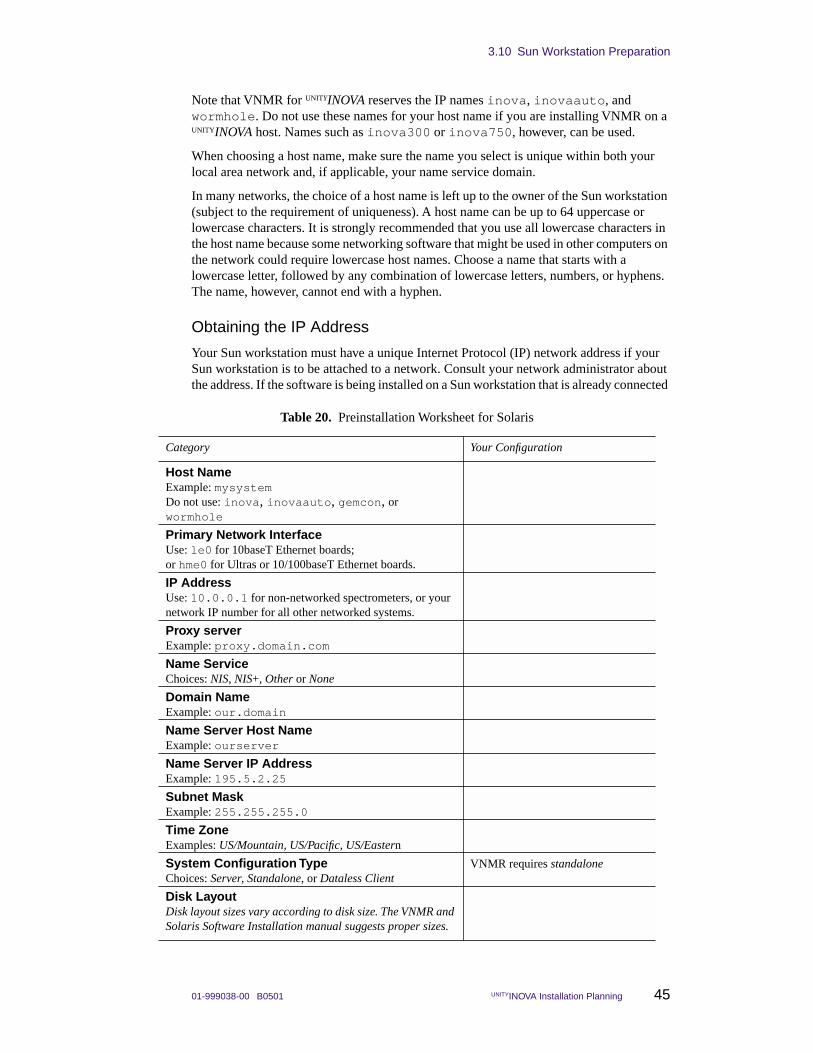
3.10 Sun Workstation Preparation
01-999038-00 B0501 UNITYINOVA Installation Planning 45
Note that VNMR for UNITYINOVA reserves the IP names inova, inovaauto, and wormhole. Do not use these names for your host name if you are installing VNMR on a UNITYINOVA host. Names such as inova300 or inova750, however, can be used.
When choosing a host name, make sure the name you select is unique within both your local area network and, if applicable, your name service domain.
In many networks, the choice of a host name is left up to the owner of the Sun workstation (subject to the requirement of uniqueness). A host name can be up to 64 uppercase or lowercase characters. It is strongly recommended that you use all lowercase characters in the host name because some networking software that might be used in other computers on the network could require lowercase host names. Choose a name that starts with a lowercase letter, followed by any combination of lowercase letters, numbers, or hyphens. The name, however, cannot end with a hyphen.
Obtaining the IP Address
Your Sun workstation must have a unique Internet Protocol (IP) network address if your Sun workstation is to be attached to a network. Consult your network administrator about the address. If the software is being installed on a Sun workstation that is already connected
Table 20. Preinstallation Worksheet for Solaris
Category Your Configuration
Host Name Example: mysystemDo not use: inova, inovaauto, gemcon, or wormhole
Primary Network InterfaceUse: le0 for 10baseT Ethernet boards; or hme0 for Ultras or 10/100baseT Ethernet boards.
IP Address Use: 10.0.0.1 for non-networked spectrometers, or your network IP number for all other networked systems.
Proxy serverExample: proxy.domain.com
Name Service Choices: NIS, NIS+, Other or None
Domain Name Example: our.domain
Name Server Host Name Example: ourserver
Name Server IP Address Example: 195.5.2.25
Subnet Mask Example: 255.255.255.0
Time Zone Examples: US/Mountain, US/Pacific, US/Eastern
System Configuration Type Choices: Server, Standalone, or Dataless Client
VNMR requires standalone
Disk Layout Disk layout sizes vary according to disk size. The VNMR and Solaris Software Installation manual suggests proper sizes.
Chapter 3. Site Preparation
46 UNITYINOVA Installation Planning 01-999038-00 B0501
to a network, the command ypcat hosts | grep `uname -n` can be used to display the IP address of your Sun workstation. Note the use of back quotes ( ` ) in this command.
If NIS is not enabled, use the command: cat /etc/hosts | grep uname -n
One of the IP addresses specified in RFC1597 must be available. These are:
10.0.0.x172.16.0.x192.168.0.x
where x is 1 through 4.
Selecting a Subnet Mask
The subnet mask is a number that is used to split IP addresses into the network (Internet) and host parts. If your site does not use multiple subnets, use the default number; otherwise, consult your network administrator. For a Sun workstation connected to a network, the command cat /etc/netmasks can be used.
Selecting the Name Service Type
The name service prompt allows choosing between NIS, NIS+, and none. If you choose NIS or NIS+, you need to enter the host name and the IP address of the computer from which you receive the service. If you choose none, you are not prompted for additional information. Ask your network administrator what name service the network uses.
Entering the host Name and IP Address of the Name Server
If you select either NIS or NIS+ as the name service type, it is assumed that there is another computer on the network that is the current NIS or NIS+ server. You are asked to enter the host name and IP address of the server that provides the name service. On an existing computer, the server’s name can be displayed by entering the command ypwhich. The server’s IP address and other information can be displayed by entering the command ypcat hosts | grep `ypwhich`. Again, note the use of back quotes ( ` ).
Domain Name
The domain name is the name assigned to a group of computers that are administered together. All computers in the group (domain) are accessed by the same NIS or NIS+ maps. Your network administrator should be able to provide the domain name. You can also find your domain name by entering the command domainname.
Setting the Time Zone
Solaris software uses world time zones and automatically adjusts for daylight-savings time if appropriate. Time zones are specified by name, such as “US/Central.”
Disk Layout
Your Sun workstation must contain at least one hard disk drive. See the Varian manual VNMR and Solaris Software Installation for disk layout requirements.
01-999038-00 B0501 UNITYINOVA Installation Planning 47
Chapter 4. Installation Supplies
Sections in this chapter:
• 4.1 “Required Installation Supplies and Equipment” this page
• 4.2 “Recommended Installation Supplies and Equipment” page 51
• 4.3 “LC-NMR Equipment, Supplies, and Solvents” page 51
Certain supplies not provided by Varian, such as helium and nitrogen supplies, must be obtained by the customer before the Varian installation engineer can start the installation.
4.1 Required Installation Supplies and EquipmentThe installation engineer will need the following non-Varian supplies and equipment during installation:
• Liquid helium supply
• Liquid nitrogen supply
• Helium gas supply
• Nitrogen gas supply
• Face mask and thermal gloves
• Heat gun
• Nonferromagnetic ladder
• Hoist
• Isopropyl alcohol and acetone
Locating a reliable local source of liquid helium and nitrogen is particularly important. As soon as possible after ordering a system, make arrangements for an initial delivery and an ongoing supply of liquid helium and nitrogen.
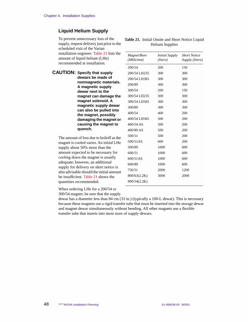
Chapter 4. Installation Supplies
48 UNITYINOVA Installation Planning 01-999038-00 B0501
Liquid Helium Supply
To prevent unnecessary loss of the supply, request delivery just prior to the scheduled visit of the Varian installation engineer. Table 21 lists the amount of liquid helium (LHe) recommended at installation.
CAUTION: Specify that supply dewars be made of nonmagnetic materials. A magnetic supply dewar next to the magnet can damage the magnet solenoid. A magnetic supply dewar can also be pulled into the magnet, possibly damaging the magnet or causing the magnet to quench.
The amount of loss due to boiloff as the magnet is cooled varies. An initial LHe supply about 50% more than the amount expected to be necessary for cooling down the magnet is usually adequate; however, an additional supply for delivery on short notice is also advisable should the initial amount be insufficient. Table 21 shows the quantities recommended.
When ordering LHe for a 200/54 or 300/54 magnet, be sure that the supply dewar has a diameter less than 84 cm (33 in.) (typically a 100-L dewar). This is necessary because these magnets use a rigid transfer tube that must be inserted into the storage dewar and magnet dewar simultaneously without bending. All other magnets use a flexible transfer tube that inserts into most sizes of supply dewars.
Table 21. Initial Onsite and Short Notice Liquid Helium Supplies
Magnet/Bore(MHz/mm)
Initial Supply(liters)
Short Notice Supply (liters)
200/54 200 150
200/54 LH235 300 300
200/54 LH365 300 300
200/89 300 300
300/54 200 150
300/54 LH235 300 300
300/54 LH365 300 300
300/89 300 300
400/54 400 200
400/54 LH365 500 200
400/54 AS 500 200
400/89 AS 500 200
500/51 500 200
500/51AS 600 200
500/89 1000 600
600/51 1000 600
600/51AS 1000 600
600/89 1000 600
750/51 2000 1200
800/63(2.2K) 3000 2000
900/54(2.2K)
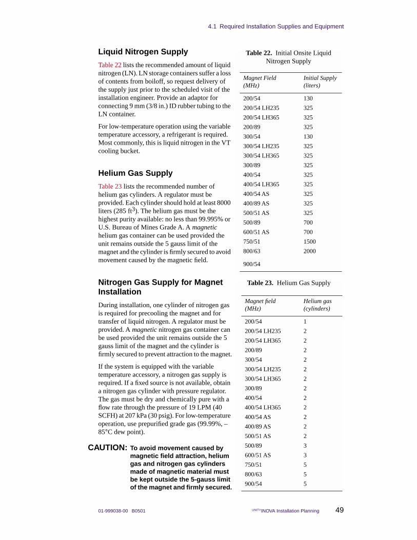
4.1 Required Installation Supplies and Equipment
01-999038-00 B0501 UNITYINOVA Installation Planning 49
Liquid Nitrogen Supply
Table 22 lists the recommended amount of liquid nitrogen (LN). LN storage containers suffer a loss of contents from boiloff, so request delivery of the supply just prior to the scheduled visit of the installation engineer. Provide an adaptor for connecting 9 mm (3/8 in.) ID rubber tubing to the LN container.
For low-temperature operation using the variable temperature accessory, a refrigerant is required. Most commonly, this is liquid nitrogen in the VT cooling bucket.
Helium Gas Supply
Table 23 lists the recommended number of helium gas cylinders. A regulator must be provided. Each cylinder should hold at least 8000 liters (285 ft3). The helium gas must be the highest purity available: no less than 99.995% or U.S. Bureau of Mines Grade A. A magnetic helium gas container can be used provided the unit remains outside the 5 gauss limit of the magnet and the cylinder is firmly secured to avoid movement caused by the magnetic field.
Nitrogen Gas Supply for Magnet Installation
During installation, one cylinder of nitrogen gas is required for precooling the magnet and for transfer of liquid nitrogen. A regulator must be provided. A magnetic nitrogen gas container can be used provided the unit remains outside the 5 gauss limit of the magnet and the cylinder is firmly secured to prevent attraction to the magnet.
If the system is equipped with the variable temperature accessory, a nitrogen gas supply is required. If a fixed source is not available, obtain a nitrogen gas cylinder with pressure regulator. The gas must be dry and chemically pure with a flow rate through the pressure of 19 LPM (40 SCFH) at 207 kPa (30 psig). For low-temperature operation, use prepurified grade gas (99.99%, –85°C dew point).
CAUTION: To avoid movement caused by magnetic field attraction, helium gas and nitrogen gas cylinders made of magnetic material must be kept outside the 5-gauss limit of the magnet and firmly secured.
Table 22. Initial Onsite Liquid Nitrogen Supply
Magnet Field(MHz)
Initial Supply(liters)
200/54 130
200/54 LH235 325
200/54 LH365 325
200/89 325
300/54 130
300/54 LH235 325
300/54 LH365 325
300/89 325
400/54 325
400/54 LH365 325
400/54 AS 325
400/89 AS 325
500/51 AS 325
500/89 700
600/51 AS 700
750/51 1500
800/63 2000
900/54
Table 23. Helium Gas Supply
Magnet field(MHz)
Helium gas(cylinders)
200/54 1
200/54 LH235 2
200/54 LH365 2
200/89 2
300/54 2
300/54 LH235 2
300/54 LH365 2
300/89 2
400/54 2
400/54 LH365 2
400/54 AS 2
400/89 AS 2
500/51 AS 2
500/89 3
600/51 AS 3
750/51 5
800/63 5
900/54 5
Chapter 4. Installation Supplies
50 UNITYINOVA Installation Planning 01-999038-00 B0501
Face Mask and Thermal Gloves
If cryogenic helium or nitrogen contact living tissue, a serious injury (similar to a burn) can occur. Order appropriate safety coverings for use during dewar servicing, including a mask that protects the face completely and a loose-fitting pair of thermal gloves.
WARNING: Avoid helium or liquid nitrogen contact with any part of the body. If liquid helium or nitrogen contact living tissue, a serious injury (similar to a burn) can occur. Never place your head over the helium and nitrogen exit tubes on top of the magnet. If helium or nitrogen contacts the body, seek medical attention, especially if the skin is blistered or the eyes are affected.
Heat Gun
Acquire a 1600 W heat gun (Dayton Model 27046 or equivalent) and a heavy-duty extension cord for thawing ice accumulation and drying out moisture on dewar servicing equipment.
CAUTION: These heat guns contain ferrous magnetic materials.
Nonferromagnetic Ladder
Acquire a 180cm (6 ft) nonferromagnetic ladder for reaching the top of the dewar while inserting and removing the helium transfer tube. The ladder should be sturdy and self-supporting with rubber feet. A somewhat taller ladder 250–300 cm (8–10 ft) is recommended for 750- and 800-MHz magnets.
Hoist
A hoist must be available to remove the magnet from the crate, assemble it, and move it into place. The capacity of the hoist depends on the weight of the magnet being installed. Table 5 on page 22 specifies magnet weights. Allow a safety factor of at least 100% above the weight shown. Be sure adequate space is available for bringing the hoist and magnet in through the lab door.
WARNING: Death of serious injury may result if the magnet is lifted with improperly assembled or improperly rated equipment.
The hoist can be a chain hoist suspended from a moveable mechanism, such as an A-frame, or it can be permanently fixed above the area designated for the magnet, such as a beam. A vertical lifting device is required for magnets with antivibration legs; this vertical lifting device would eliminate the need for a “cherry picker” type device. Consult your plant facilities department or authorized Varian representative to ensure that adequate facilities are available.
Isopropyl Alcohol and Acetone Solvents
Obtain 1 pint (500 cm3) each of isopropyl alcohol and acetone. These solvents are needed to clean the magnet parts before assembly. Acetone should never be used for general cleaning as it can damage some plastics and paints.
4.2 Recommended Installation Supplies and Equipment
01-999038-00 B0501 UNITYINOVA Installation Planning 51
4.2 Recommended Installation Supplies and EquipmentIn addition to the required installation supplies and equipment, the following items are recommended:
• Cryogenic equipment rack
• Electrical power surge protector
• Monitor degaussing coil
Cryogenic Equipment RackVarious items are used around the magnet for routine maintenance and handling, including a helium transfer tube, a flutter tube, Tygon tubing, and stingers. To protect the cryogenic equipment from damage and to keep it conveniently available, provide a rack to hold the items. A 1.2 m × 2.4 m (4 ft × 8 ft) peg board hung on a laboratory wall, with wood or plastic pegs, works very well.
Electrical Power Surge Protector To protect the delicate electrical components of the sun workstation (monitor, disk drive unit, CPU base, etc.), a good quality surge protector should be inserted in the power circuit serving the components. A single surge protector with six outlets should suffice if the components are located relatively close to one another. Contact an electronic professional for advice on quality surge protection in your area. If a UPS is to be used for line conditioning, a surge protector is unnecessary.
Monitor Degaussing Coil The workstation monitor can gradually become somewhat magnetized due to its proximity to the magnet. This condition can be corrected with a degaussing coil. If the host workstation system is to be located near the edge of the 1–2 gauss stray field of the magnet, the degaussing coil is a necessity. For example, GC Electonics model 9317 (1801 Morgan St., Rockford Il., 61102, (815) 968-9661).
4.3 LC-NMR Equipment, Supplies, and SolventsYou must have the following equipment, samples, and solvents on hand before the LC-NMR accessory is installed:
• A nonmagnetic table (at least 3 ft by 4 ft) to hold the LC hardware.
• Either gas cylinder of helium, outfitted with 0.25-inch OD Teflon tubing with aerator (this will be used for sparging the acetonitrile solvent), or the necessary degassing equipment. Do not use an aspirator.
• At least 300 mL of D2O, 99.8 atom percent or better.
• At least 100 mL of acetone-d6.
• At least 300 mL of OmniSolv brand acetonitrile (EM Science part no. AX014-l).
• Research grade sucrose.
• At least three, 100-mL volumetric flasks for preparing standard samples.
• An appropriate waste container for HPLC effluent. The cover of the container must have a hole in the top of about 2 mm diameter. The hole is used for the outlet of the LC-NMR Microflow probe.
• Air supply for the pneumatic valve.

Chapter 4. Installation Supplies
52 UNITYINOVA Installation Planning 01-999038-00 B0501

01-999038-00 B0501 UNITYINOVA Installation Planning 53
Chapter 5. Stray Magnetic Fields
Sections in this chapter:
• 5.1 “Safety Hazards of Strong Magnetic Fields” this page
• 5.2 “Stray Field Plots” page 55
• 5.3 “Posting Requirements for Magnetic Field Warning Signs” page 67
The magnetic field is typically the biggest concern when planning for an NMR system. This chapter contains magnetic field safety information and stray field plots.
5.1 Safety Hazards of Strong Magnetic FieldsThe potential safety hazards of strong magnetic fields for devices such as certain pacemakers must be understood and planned for. A set of plots indicating the magnitude of the stray fields for each type of magnet is included in Section 5.2, “Stray Field Plots,” on page 55. These plots show typical levels of stray field. Actual levels may vary and should be checked after a particular magnet has been installed.
WARNING: Cardiac pacemaker wearers must remain outside the 5-gauss perimeter from the magnet until safety is clearly established. An NMR superconducting magnet generates strong magnetic and electromagnetic fields that can inhibit operation of some cardiac pacemakers, which could result in death or serious injury to the user. Consult the pacemaker user’s manual, contact the manufacturer, or confer with a physician to determine the effect on a specific pacemaker. Varian provides signs with each system to warn pacemaker wearers of this hazard. Post the signs according to Section 5.3, “Posting Requirements for Magnetic Field Warning Signs,” on page 67.
Pacemakers
Cardiac pacemaker wearers must not enter a zone that would subject a cardiac pacemaker to a magnetic intensity that could cause adverse effects. In some instances, this zone might include space on the floors directly above and below the magnet. For assistance in determining the effect of a system on pacemaker, consult the pacemaker user’s manual, contact the pacemaker manufacturer, or confer with a physician to determine the effect on a specific pacemaker. Actual levels vary and should be checked after a particular magnet has been installed.
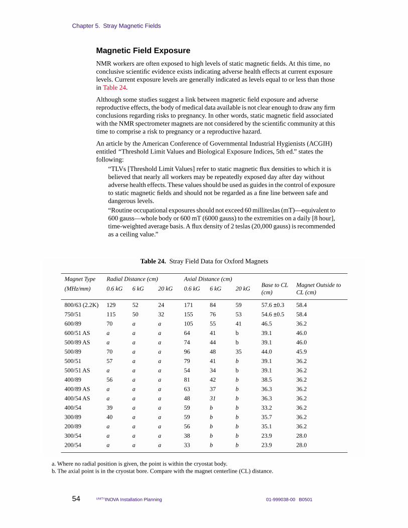
Chapter 5. Stray Magnetic Fields
54 UNITYINOVA Installation Planning 01-999038-00 B0501
Magnetic Field Exposure
NMR workers are often exposed to high levels of static magnetic fields. At this time, no conclusive scientific evidence exists indicating adverse health effects at current exposure levels. Current exposure levels are generally indicated as levels equal to or less than those in Table 24.
Although some studies suggest a link between magnetic field exposure and adverse reproductive effects, the body of medical data available is not clear enough to draw any firm conclusions regarding risks to pregnancy. In other words, static magnetic field associated with the NMR spectrometer magnets are not considered by the scientific community at this time to comprise a risk to pregnancy or a reproductive hazard.
An article by the American Conference of Governmental Industrial Hygienists (ACGIH) entitled “Threshold Limit Values and Biological Exposure Indices, 5th ed.” states the following:
“TLVs [Threshold Limit Values] refer to static magnetic flux densities to which it is believed that nearly all workers may be repeatedly exposed day after day without adverse health effects. These values should be used as guides in the control of exposure to static magnetic fields and should not be regarded as a fine line between safe and dangerous levels.
“Routine occupational exposures should not exceed 60 milliteslas (mT)—equivalent to 600 gauss—whole body or 600 mT (6000 gauss) to the extremities on a daily [8 hour], time-weighted average basis. A flux density of 2 teslas (20,000 gauss) is recommended as a ceiling value.”
Table 24. Stray Field Data for Oxford Magnets
Magnet Type Radial Distance (cm) Axial Distance (cm)
(MHz/mm) 0.6 kG 6 kG 20 kG 0.6 kG 6 kG 20 kGBase to CL (cm)
Magnet Outside to CL (cm)
800/63 (2.2K) 129 52 24 171 84 59 57.6 ±0.3 58.4
750/51 115 50 32 155 76 53 54.6 ±0.5 58.4
600/89 70 a a 105 55 41 46.5 36.2
600/51 AS a a a 64 41 b 39.1 46.0
500/89 AS a a a 74 44 b 39.1 46.0
500/89 70 a a 96 48 35 44.0 45.9
500/51 57 a a 79 41 b 39.1 36.2
500/51 AS a a a 54 34 b 39.1 36.2
400/89 56 a a 81 42 b 38.5 36.2
400/89 AS a a a 63 37 b 36.3 36.2
400/54 AS a a a 48 31 b 36.3 36.2
400/54 39 a a 59 b b 33.2 36.2
300/89 40 a a 59 b b 35.7 36.2
200/89 a a a 56 b b 35.1 36.2
300/54 a a a 38 b b 23.9 28.0
200/54 a a a 33 b b 23.9 28.0
a. Where no radial position is given, the point is within the cryostat body.b. The axial point is in the cryostat bore. Compare with the magnet centerline (CL) distance.
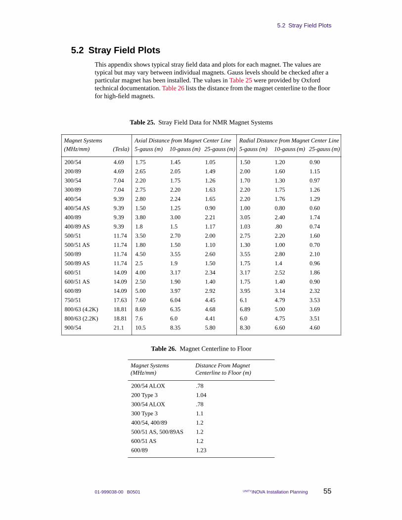
5.2 Stray Field Plots
01-999038-00 B0501 UNITYINOVA Installation Planning 55
5.2 Stray Field PlotsThis appendix shows typical stray field data and plots for each magnet. The values are typical but may vary between individual magnets. Gauss levels should be checked after a particular magnet has been installed. The values in Table 25 were provided by Oxford technical documentation. Table 26 lists the distance from the magnet centerline to the floor for high-field magnets.
Table 25. Stray Field Data for NMR Magnet Systems
Magnet Systems Axial Distance from Magnet Center Line Radial Distance from Magnet Center Line
(MHz/mm) (Tesla) 5-gauss (m) 10-gauss (m) 25-gauss (m) 5-gauss (m) 10-gauss (m) 25-gauss (m)
200/54 4.69 1.75 1.45 1.05 1.50 1.20 0.90
200/89 4.69 2.65 2.05 1.49 2.00 1.60 1.15
300/54 7.04 2.20 1.75 1.26 1.70 1.30 0.97
300/89 7.04 2.75 2.20 1.63 2.20 1.75 1.26
400/54 9.39 2.80 2.24 1.65 2.20 1.76 1.29
400/54 AS 9.39 1.50 1.25 0.90 1.00 0.80 0.60
400/89 9.39 3.80 3.00 2.21 3.05 2.40 1.74
400/89 AS 9.39 1.8 1.5 1.17 1.03 .80 0.74
500/51 11.74 3.50 2.70 2.00 2.75 2.20 1.60
500/51 AS 11.74 1.80 1.50 1.10 1.30 1.00 0.70
500/89 11.74 4.50 3.55 2.60 3.55 2.80 2.10
500/89 AS 11.74 2.5 1.9 1.50 1.75 1.4 0.96
600/51 14.09 4.00 3.17 2.34 3.17 2.52 1.86
600/51 AS 14.09 2.50 1.90 1.40 1.75 1.40 0.90
600/89 14.09 5.00 3.97 2.92 3.95 3.14 2.32
750/51 17.63 7.60 6.04 4.45 6.1 4.79 3.53
800/63 (4.2K) 18.81 8.69 6.35 4.68 6.89 5.00 3.69
800/63 (2.2K) 18.81 7.6 6.0 4.41 6.0 4.75 3.51
900/54 21.1 10.5 8.35 5.80 8.30 6.60 4.60
Table 26. Magnet Centerline to Floor
Magnet Systems(MHz/mm)
Distance From Magnet Centerline to Floor (m)
200/54 ALOX .78
200 Type 3 1.04
300/54 ALOX .78
300 Type 3 1.1
400/54, 400/89 1.2
500/51 AS, 500/89AS 1.2
600/51 AS 1.2
600/89 1.23
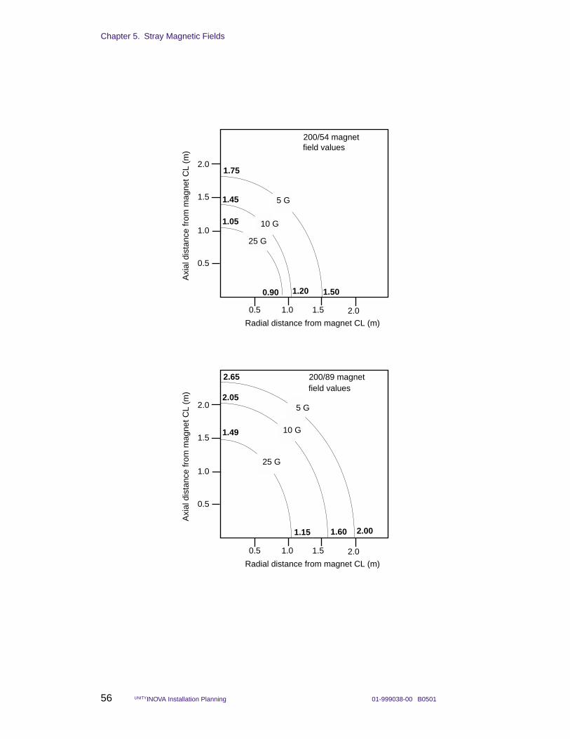
Chapter 5. Stray Magnetic Fields
56 UNITYINOVA Installation Planning 01-999038-00 B0501
field values
1.0 2.0
2.0
1.0
200/54 magnet
0.5
1.5
0.5 1.5
Axi
al d
ista
nce
from
mag
net C
L (m
)
Radial distance from magnet CL (m)
1.75
1.50
5 G1.45
1.20
10 G
0.90
1.05
25 G
field values
1.0 2.0
2.0
1.0
200/89 magnet
0.5
1.5
0.5 1.5
Axi
al d
ista
nce
from
mag
net C
L (m
)
Radial distance from magnet CL (m)
2.65
2.00
2.05
1.601.15
1.49
5 G
10 G
25 G
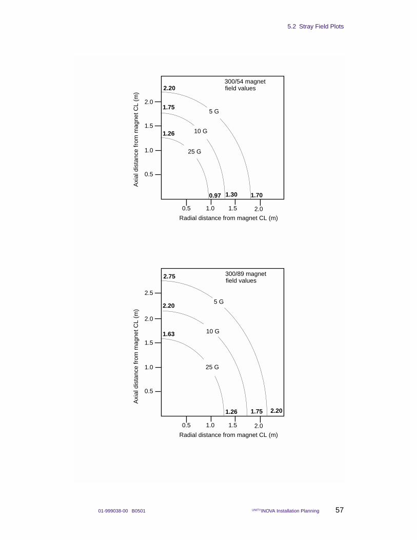
5.2 Stray Field Plots
01-999038-00 B0501 UNITYINOVA Installation Planning 57
field values
1.0 2.0
2.0
1.0
300/54 magnet
0.5
1.5
0.5 1.5
Axi
al d
ista
nce
from
mag
net C
L (m
)
Radial distance from magnet CL (m)
2.20
1.70
1.75
1.300.97
1.26
field values
1.0 2.0
2.0
1.0
300/89 magnet
0.5
1.5
0.5 1.5
Axi
al d
ista
nce
from
mag
net C
L (m
)
Radial distance from magnet CL (m)
2.75
2.20
2.20
1.751.26
1.63
5 G
10 G
25 G
2.55 G
10 G
25 G
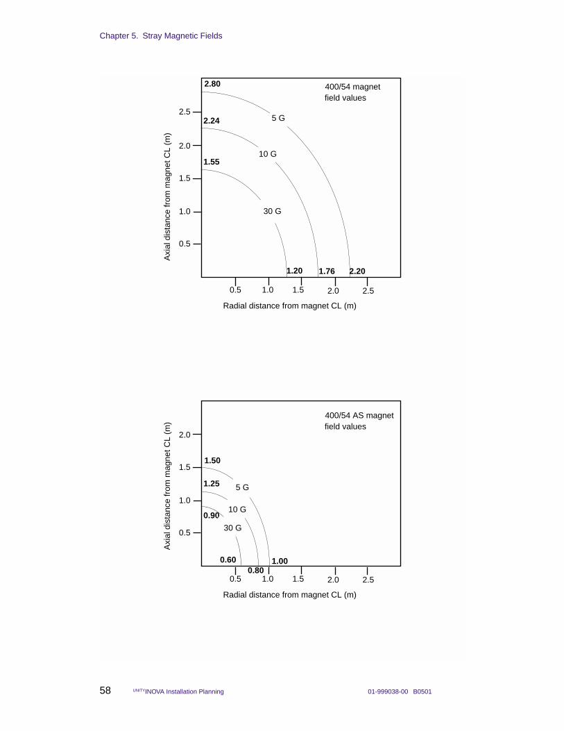
Chapter 5. Stray Magnetic Fields
58 UNITYINOVA Installation Planning 01-999038-00 B0501
field values
1.0 2.0
2.0
1.0
400/54 magnet
0.5
1.5
0.5 1.5
Axi
al d
ista
nce
from
mag
net C
L (m
)
Radial distance from magnet CL (m)
2.80
2.20
2.24
1.761.20
1.55
2.5
2.5
5 G
10 G
30 G
field values
1.0 2.0
2.0
1.0
400/54 AS magnet
0.5
1.5
0.5 1.5
Axi
al d
ista
nce
from
mag
net C
L (m
)
Radial distance from magnet CL (m)
1.50
1.00
1.25
0.800.60
0.90
2.5
5 G
10 G
30 G
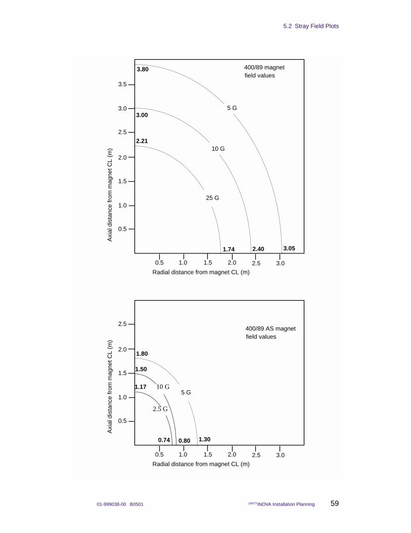
5.2 Stray Field Plots
01-999038-00 B0501 UNITYINOVA Installation Planning 59
field values
1.0 2.5
2.0
1.0
400/89 AS magnet
0.5
1.5
0.5 1.5
Axi
al d
ista
nce
from
mag
net C
L (m
)
Radial distance from magnet CL (m)
1.80
2.5
2.0 3.0
5 G10 G
2.5 G
0.74 0.80 1.30
1.50
1.17
field values
1.0 2.5
2.0
1.0
400/89 magnet
0.5
1.5
0.5 1.5
Axi
al d
ista
nce
from
mag
net C
L (m
)
Radial distance from magnet CL (m)
3.80
3.05
3.00
2.401.74
2.212.5
2.0 3.0
3.0
3.5
5 G
10 G
25 G
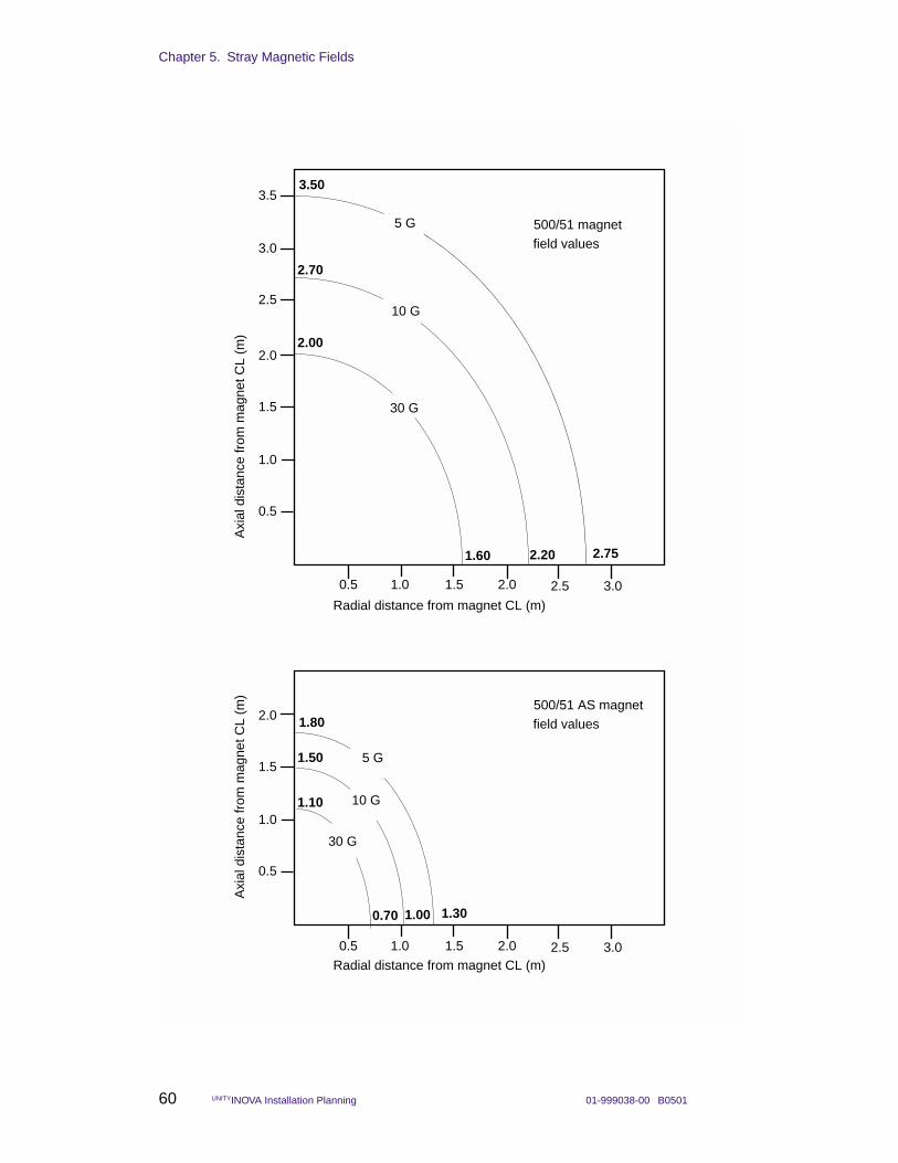
Chapter 5. Stray Magnetic Fields
60 UNITYINOVA Installation Planning 01-999038-00 B0501
field values
1.0 2.5
2.0
1.0
500/51 magnet
0.5
1.5
0.5 1.5
Axi
al d
ista
nce
from
mag
net C
L (m
)
Radial distance from magnet CL (m)
3.50
2.75
2.70
2.201.60
2.00
2.5
2.0 3.0
3.0
3.5
5 G
10 G
30 G
field values
1.0 2.5
2.0
1.0
500/51 AS magnet
0.5
1.5
0.5 1.5
Axi
al d
ista
nce
from
mag
net C
L (m
)
Radial distance from magnet CL (m)
1.80
1.30
1.50
1.000.70
1.10
2.0 3.0
5 G
10 G
30 G
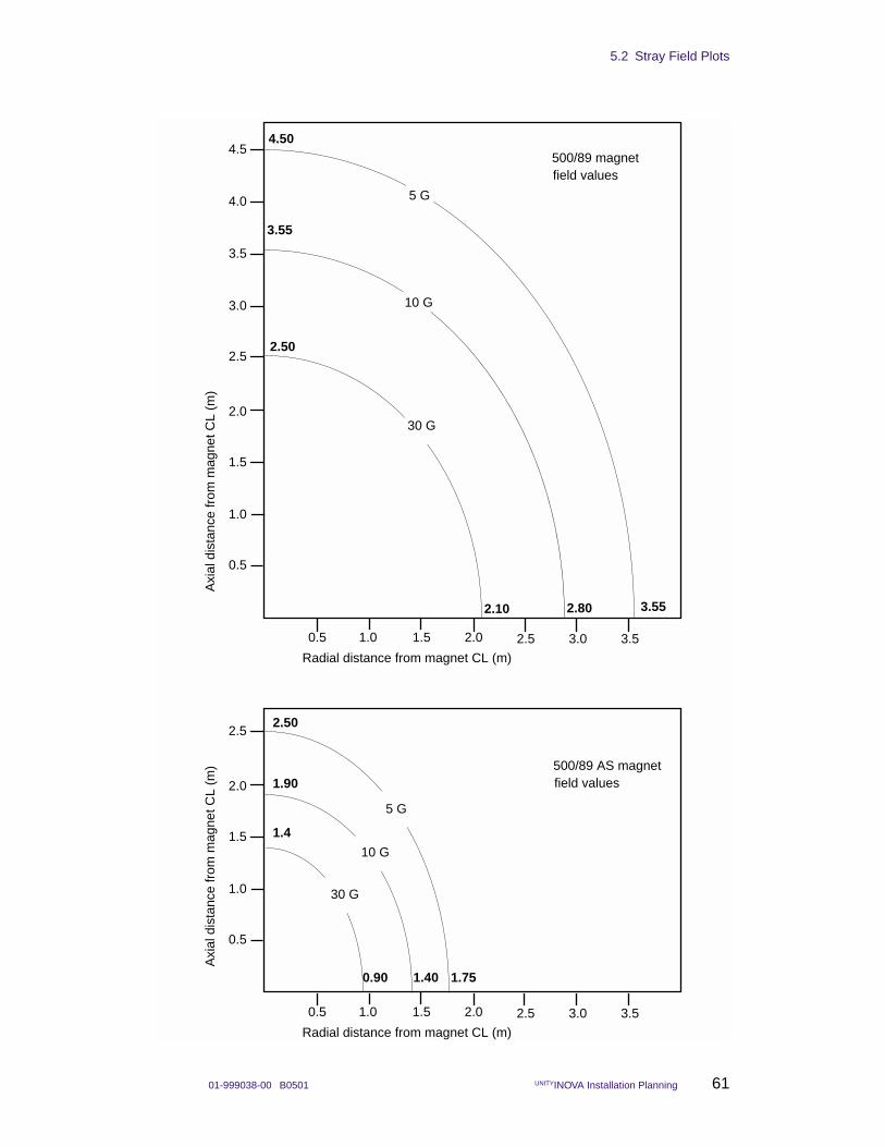
5.2 Stray Field Plots
01-999038-00 B0501 UNITYINOVA Installation Planning 61
field values
1.0 2.5
2.0
1.0
500/89 magnet
0.5
1.5
0.5 1.5
Axi
al d
ista
nce
from
mag
net C
L (m
)
Radial distance from magnet CL (m)
4.50
3.55
3.55
2.802.10
2.502.5
2.0 3.0
3.0
3.5
4.0
4.5
3.5
5 G
10 G
30 G
field values
1.0 2.5
2.0
1.0
500/89 AS magnet
0.5
1.5
0.5 1.5
Axi
al d
ista
nce
from
mag
net C
L (m
)
Radial distance from magnet CL (m)
1.75
2.502.5
2.0 3.0 3.5
5 G
10 G
30 G
1.90
1.4
1.400.90
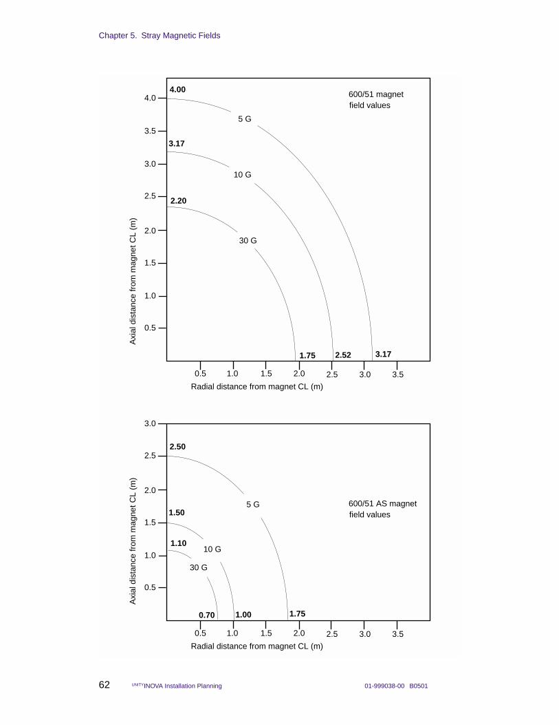
Chapter 5. Stray Magnetic Fields
62 UNITYINOVA Installation Planning 01-999038-00 B0501
field values
1.0 2.5
2.0
1.0
600/51 magnet
0.5
1.5
0.5 1.5
Axi
al d
ista
nce
from
mag
net C
L (m
)
Radial distance from magnet CL (m)
4.00
3.17
3.17
2.521.75
2.202.5
2.0 3.0
3.0
3.5
4.0
3.5
5 G
10 G
30 G
1.10
1.50
2.50
field values600/51 AS magnet
1.0 2.5
2.0
1.0
0.5
1.5
0.5 1.5
Axi
al d
ista
nce
from
mag
net C
L (m
)
Radial distance from magnet CL (m)
1.751.000.70
2.5
2.0 3.0
3.0
3.5
5 G
10 G
30 G
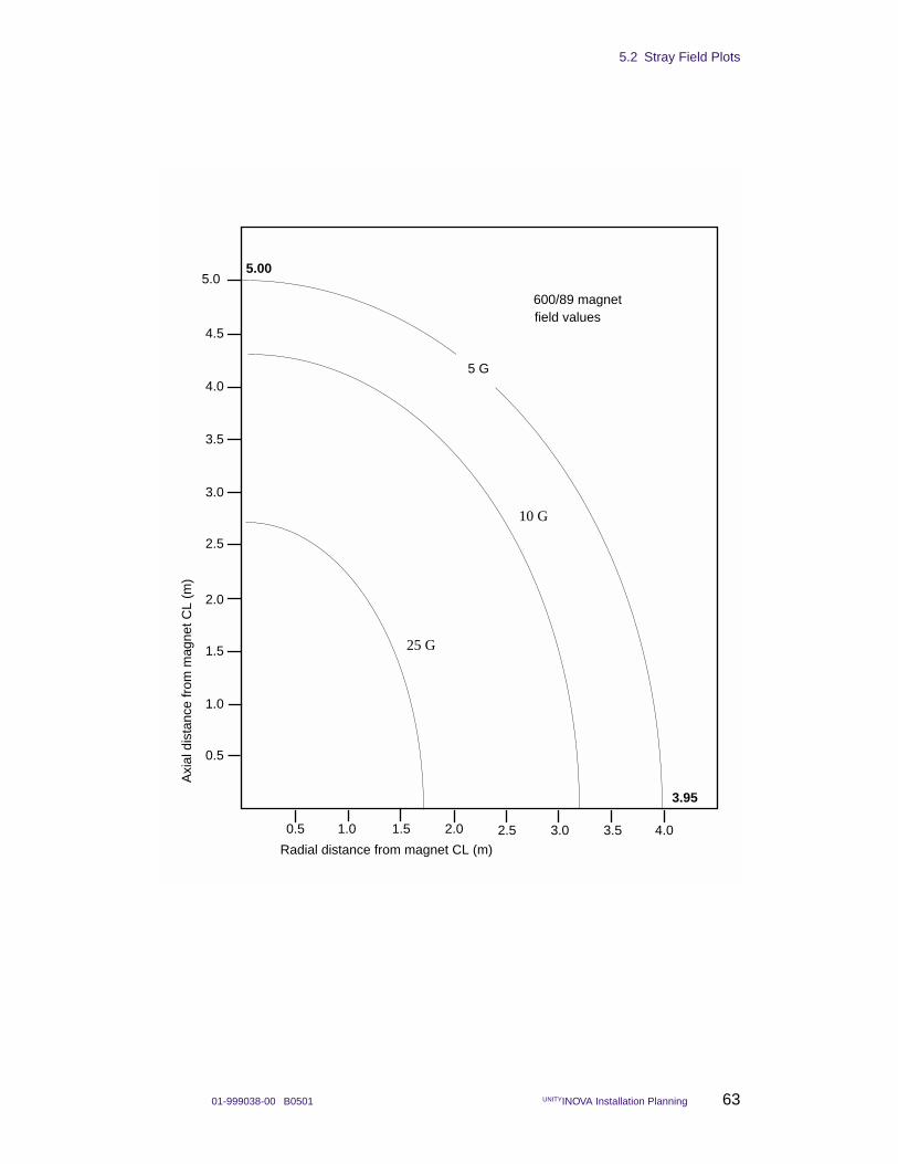
5.2 Stray Field Plots
01-999038-00 B0501 UNITYINOVA Installation Planning 63
field values
1.0 2.5
2.0
1.0
600/89 magnet
0.5
1.5
0.5 1.5
Axi
al d
ista
nce
from
mag
net C
L (m
)
Radial distance from magnet CL (m)
5.00
3.95
2.5
2.0 3.0
3.0
3.5
4.0
4.5
3.5
5 G
5.0
4.0
25 G
10 G
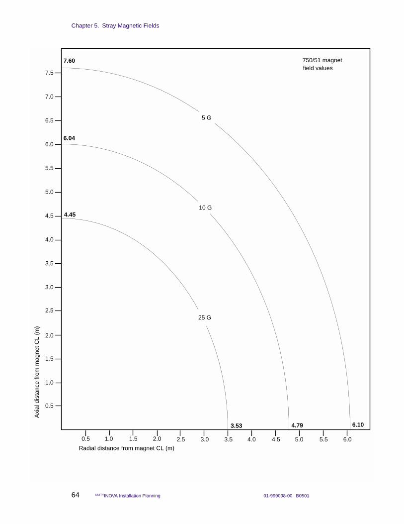
Chapter 5. Stray Magnetic Fields
64 UNITYINOVA Installation Planning 01-999038-00 B0501
field values
1.0 2.5
2.0
1.0
750/51 magnet
0.5
1.5
0.5 1.5
Axi
al d
ista
nce
from
mag
net C
L (m
)
Radial distance from magnet CL (m)
7.60
6.10
6.04
4.793.53
4.45
2.5
2.0 3.0
3.0
3.5
4.0
4.5
3.5
5.0
5.5
6.0
6.5
7.0
7.5
4.0 4.5 5.0 5.5 6.0
5 G
10 G
25 G
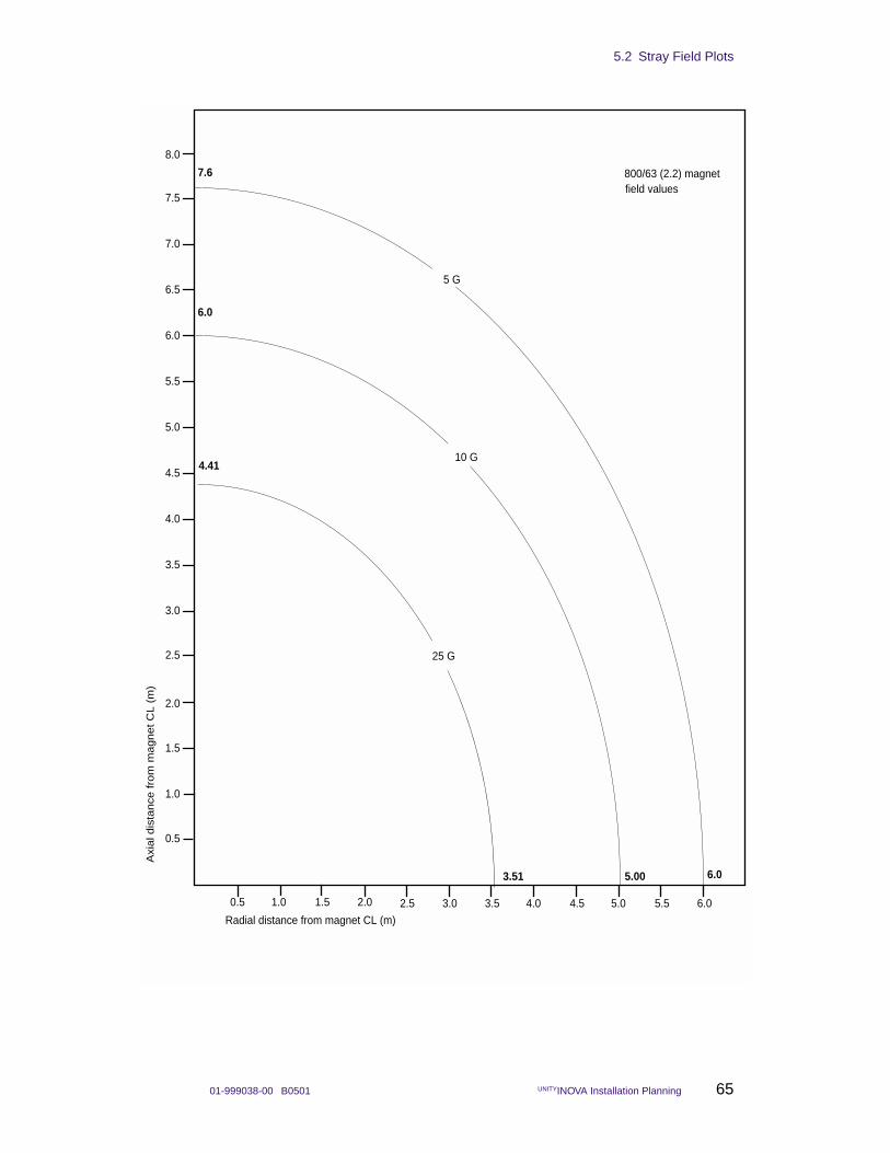
5.2 Stray Field Plots
01-999038-00 B0501 UNITYINOVA Installation Planning 65
field values
1.0 2.5
2.0
1.0
800/63 (2.2) magnet
0.5
1.5
0.5 1.5
Axi
al d
ista
nce
fro
m m
agnet C
L (
m)
Radial distance from magnet CL (m)
6.0
5.00
2.5
2.0 3.0
3.0
3.5
4.0
4.5
3.5
5.0
5.5
6.0
6.5
7.0
7.5
4.0 4.5 5.0 5.5 6.0
5 G
10 G
25 G
8.0
7.6
4.41
3.51 6.0
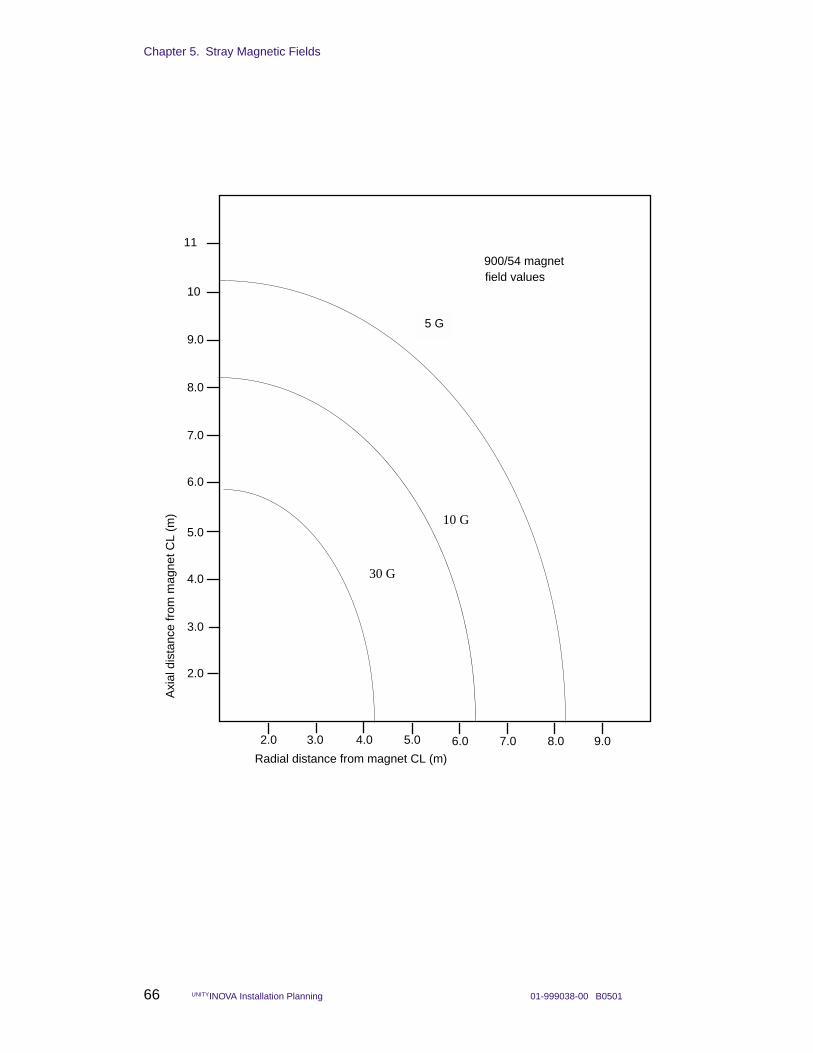
Chapter 5. Stray Magnetic Fields
66 UNITYINOVA Installation Planning 01-999038-00 B0501
field values
3.0 6.0
5.0
3.0
900/54 magnet
2.0
4.0
2.0 4.0
Axi
al d
ista
nce
from
mag
net C
L (m
)
Radial distance from magnet CL (m)
6.0
5.0 7.0
7.0
8.0
9.0
10
8.0
5 G
11
9.0
30 G
10 G
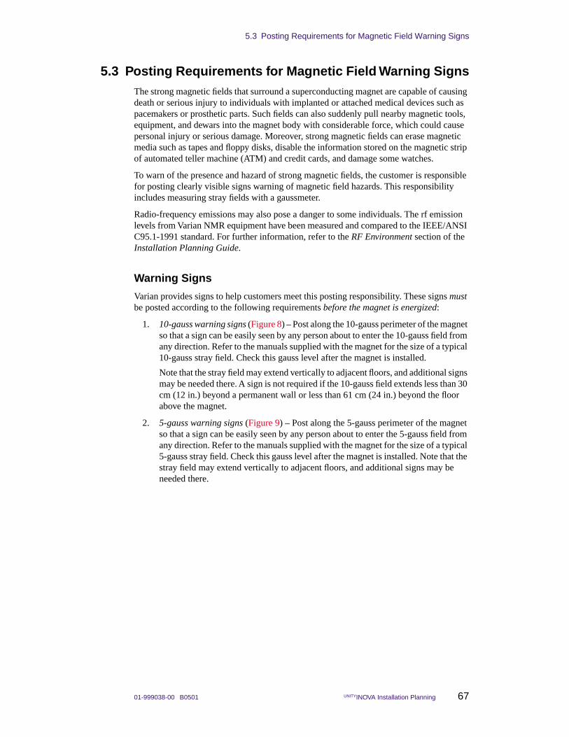
5.3 Posting Requirements for Magnetic Field Warning Signs
01-999038-00 B0501 UNITYINOVA Installation Planning 67
5.3 Posting Requirements for Magnetic Field Warning SignsThe strong magnetic fields that surround a superconducting magnet are capable of causing death or serious injury to individuals with implanted or attached medical devices such as pacemakers or prosthetic parts. Such fields can also suddenly pull nearby magnetic tools, equipment, and dewars into the magnet body with considerable force, which could cause personal injury or serious damage. Moreover, strong magnetic fields can erase magnetic media such as tapes and floppy disks, disable the information stored on the magnetic strip of automated teller machine (ATM) and credit cards, and damage some watches.
To warn of the presence and hazard of strong magnetic fields, the customer is responsible for posting clearly visible signs warning of magnetic field hazards. This responsibility includes measuring stray fields with a gaussmeter.
Radio-frequency emissions may also pose a danger to some individuals. The rf emission levels from Varian NMR equipment have been measured and compared to the IEEE/ANSI C95.1-1991 standard. For further information, refer to the RF Environment section of the Installation Planning Guide.
Warning Signs
Varian provides signs to help customers meet this posting responsibility. These signs must be posted according to the following requirements before the magnet is energized:
1. 10-gauss warning signs (Figure 8) – Post along the 10-gauss perimeter of the magnet so that a sign can be easily seen by any person about to enter the 10-gauss field from any direction. Refer to the manuals supplied with the magnet for the size of a typical 10-gauss stray field. Check this gauss level after the magnet is installed.
Note that the stray field may extend vertically to adjacent floors, and additional signs may be needed there. A sign is not required if the 10-gauss field extends less than 30 cm (12 in.) beyond a permanent wall or less than 61 cm (24 in.) beyond the floor above the magnet.
2. 5-gauss warning signs (Figure 9) – Post along the 5-gauss perimeter of the magnet so that a sign can be easily seen by any person about to enter the 5-gauss field from any direction. Refer to the manuals supplied with the magnet for the size of a typical 5-gauss stray field. Check this gauss level after the magnet is installed. Note that the stray field may extend vertically to adjacent floors, and additional signs may be needed there.
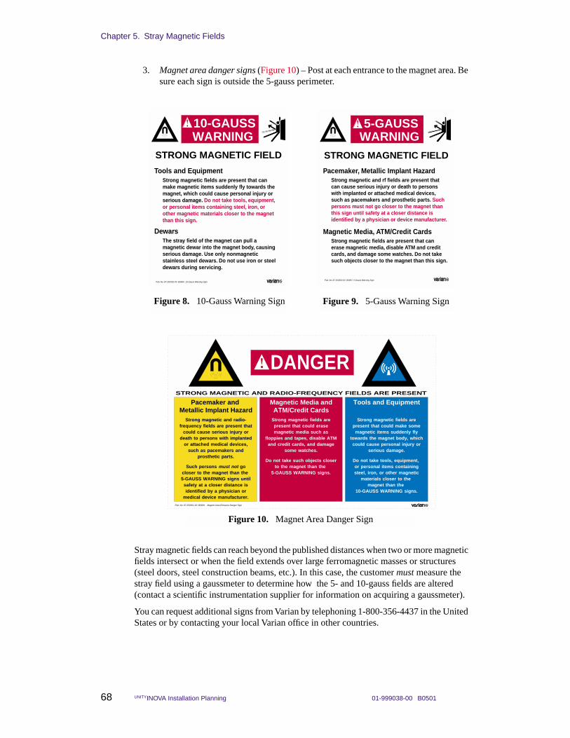
Chapter 5. Stray Magnetic Fields
68 UNITYINOVA Installation Planning 01-999038-00 B0501
3. Magnet area danger signs (Figure 10) – Post at each entrance to the magnet area. Be sure each sign is outside the 5-gauss perimeter.
Stray magnetic fields can reach beyond the published distances when two or more magnetic fields intersect or when the field extends over large ferromagnetic masses or structures (steel doors, steel construction beams, etc.). In this case, the customer must measure the stray field using a gaussmeter to determine how the 5- and 10-gauss fields are altered (contact a scientific instrumentation supplier for information on acquiring a gaussmeter).
You can request additional signs from Varian by telephoning 1-800-356-4437 in the United States or by contacting your local Varian office in other countries.
Tools and EquipmentStrong magnetic fields are present that can make magnetic items suddenly fly towards the magnet, which could cause personal injury or serious damage. Do not take tools, equipment, or personal items containing steel, iron, or other magnetic materials closer to the magnet than this sign.
DewarsThe stray field of the magnet can pull a magnetic dewar into the magnet body, causing serious damage. Use only nonmagnetic stainless steel dewars. Do not use iron or steel dewars during servicing.
STRONG MAGNETIC FIELD
Pub. No. 87-250302-00 B0694 10-Gauss Warning Sign
10-GAUSSWARNING
Figure 8. 10-Gauss Warning Sign
Pacemaker, Metallic Implant HazardStrong magnetic and rf fields are present that can cause serious injury or death to persons with implanted or attached medical devices, such as pacemakers and prosthetic parts. Such persons must not go closer to the magnet than this sign until safety at a closer distance is identified by a physician or device manufacturer.
Magnetic Media, ATM/Credit CardsStrong magnetic fields are present that can erase magnetic media, disable ATM and credit cards, and damage some watches. Do not take such objects closer to the magnet than this sign.
STRONG MAGNETIC FIELD
Pub. No. 87-250303-00 B0694 5-Gauss Warning Sign
5-GAUSSWARNING
Figure 9. 5-Gauss Warning Sign
STRONG MAGNETIC AND RADIO-FREQUENCY FIELDS ARE PRESENT
Pub. No. 87-250301-00 B0694 Magnet Area Entrance Danger Sign
DANGER
Pacemaker and Metallic Implant Hazard
Strong magnetic and radio-frequency fields are present that
could cause serious injury or death to persons with implanted
or attached medical devices, such as pacemakers and
prosthetic parts.
Such persons must not go closer to the magnet than the 5-GAUSS WARNING signs until
safety at a closer distance is identified by a physician or
medical device manufacturer.
Tools and Equipment
Strong magnetic fields are present that could make some magnetic items suddenly fly
towards the magnet body, which could cause personal injury or
serious damage.
Do not take tools, equipment, or personal items containing steel, iron, or other magnetic
materials closer to the magnet than the
10-GAUSS WARNING signs.
Magnetic Media andATM/Credit Cards
Strong magnetic fields are present that could erase magnetic media such as
floppies and tapes, disable ATM and credit cards, and damage
some watches.
Do not take such objects closer to the magnet than the
5-GAUSS WARNING signs.
Figure 10. Magnet Area Danger Sign
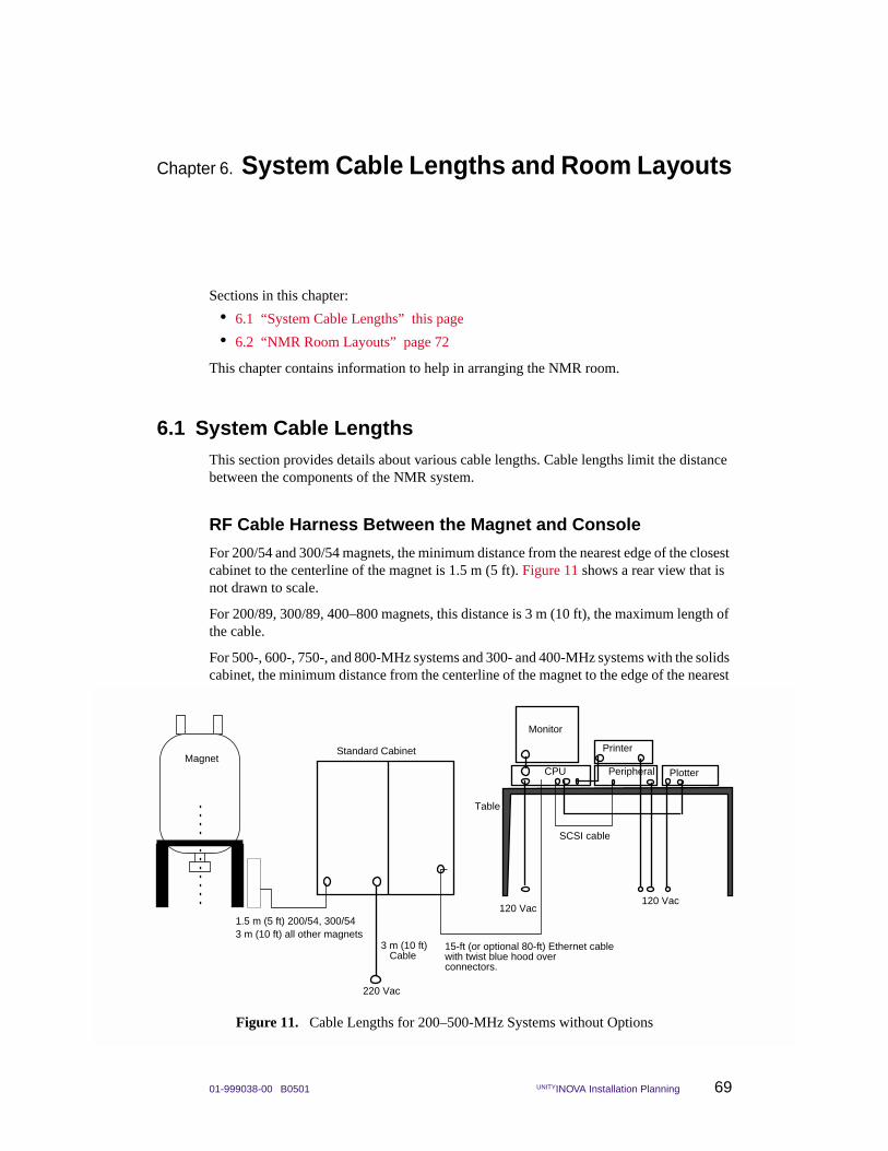
01-999038-00 B0501 UNITYINOVA Installation Planning 69
Chapter 6. System Cable Lengths and Room Layouts
Sections in this chapter:
• 6.1 “System Cable Lengths” this page
• 6.2 “NMR Room Layouts” page 72
This chapter contains information to help in arranging the NMR room.
6.1 System Cable LengthsThis section provides details about various cable lengths. Cable lengths limit the distance between the components of the NMR system.
RF Cable Harness Between the Magnet and Console
For 200/54 and 300/54 magnets, the minimum distance from the nearest edge of the closest cabinet to the centerline of the magnet is 1.5 m (5 ft). Figure 11 shows a rear view that is not drawn to scale.
For 200/89, 300/89, 400–800 magnets, this distance is 3 m (10 ft), the maximum length of the cable.
For 500-, 600-, 750-, and 800-MHz systems and 300- and 400-MHz systems with the solids cabinet, the minimum distance from the centerline of the magnet to the edge of the nearest
220 Vac
Printer
Monitor
Table
120 Vac
PlotterCPU Peripheral
Standard Cabinet
3 m (10 ft)Cable
1.5 m (5 ft) 200/54, 300/54
SCSI cable
120 Vac
Magnet
15-ft (or optional 80-ft) Ethernet cablewith twist blue hood over connectors.
3 m (10 ft) all other magnets
Figure 11. Cable Lengths for 200–500-MHz Systems without Options
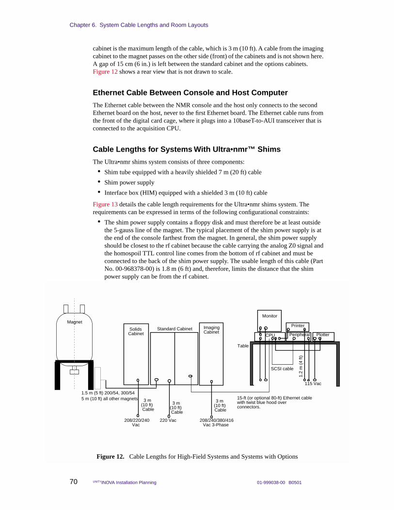
Chapter 6. System Cable Lengths and Room Layouts
70 UNITYINOVA Installation Planning 01-999038-00 B0501
cabinet is the maximum length of the cable, which is 3 m (10 ft). A cable from the imaging cabinet to the magnet passes on the other side (front) of the cabinets and is not shown here. A gap of 15 cm (6 in.) is left between the standard cabinet and the options cabinets. Figure 12 shows a rear view that is not drawn to scale.
Ethernet Cable Between Console and Host Computer
The Ethernet cable between the NMR console and the host only connects to the second Ethernet board on the host, never to the first Ethernet board. The Ethernet cable runs from the front of the digital card cage, where it plugs into a 10baseT-to-AUI transceiver that is connected to the acquisition CPU.
Cable Lengths for Systems With Ultra•nmr™ Shims
The Ultra•nmr shims system consists of three components:
• Shim tube equipped with a heavily shielded 7 m (20 ft) cable
• Shim power supply
• Interface box (HIM) equipped with a shielded 3 m (10 ft) cable
Figure 13 details the cable length requirements for the Ultra•nmr shims system. The requirements can be expressed in terms of the following configurational constraints:
• The shim power supply contains a floppy disk and must therefore be at least outside the 5-gauss line of the magnet. The typical placement of the shim power supply is at the end of the console farthest from the magnet. In general, the shim power supply should be closest to the rf cabinet because the cable carrying the analog Z0 signal and the homospoil TTL control line comes from the bottom of rf cabinet and must be connected to the back of the shim power supply. The usable length of this cable (Part No. 00-968378-00) is 1.8 m (6 ft) and, therefore, limits the distance that the shim power supply can be from the rf cabinet.
Solids Cabinet
208/220/240Vac
220 Vac
Standard Cabinet
3 m (10 ft) Cable
Printer
Monitor
Table
115 Vac
PlotterCPU
Imaging Cabinet
208/240/380/416 Vac 3-Phase
Peripheral
3 m (10 ft) Cable
3 m (10 ft) Cable
1.2
m (
4 ft)
Magnet
SCSI cable
15-ft (or optional 80-ft) Ethernet cablewith twist blue hood over connectors.
1.5 m (5 ft) 200/54, 300/545 m (10 ft) all other magnets
Figure 12. Cable Lengths for High-Field Systems and Systems with Options
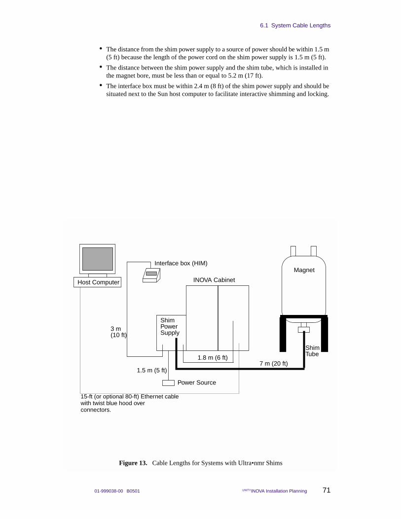
6.1 System Cable Lengths
01-999038-00 B0501 UNITYINOVA Installation Planning 71
• The distance from the shim power supply to a source of power should be within 1.5 m (5 ft) because the length of the power cord on the shim power supply is 1.5 m (5 ft).
• The distance between the shim power supply and the shim tube, which is installed in the magnet bore, must be less than or equal to 5.2 m (17 ft).
• The interface box must be within 2.4 m (8 ft) of the shim power supply and should be situated next to the Sun host computer to facilitate interactive shimming and locking.
Host Computer
Interface box (HIM)
Shim
Shim
7 m (20 ft)
3 m
1.8 m (6 ft)
Power Source
1.5 m (5 ft)
Magnet
INOVA Cabinet
Tube
PowerSupply(10 ft)
15-ft (or optional 80-ft) Ethernet cablewith twist blue hood over connectors.
Figure 13. Cable Lengths for Systems with Ultra•nmr Shims
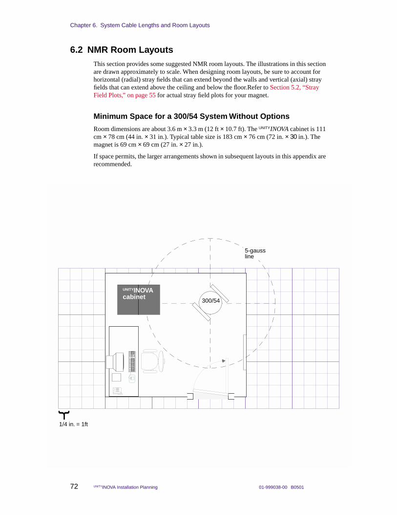
Chapter 6. System Cable Lengths and Room Layouts
72 UNITYINOVA Installation Planning 01-999038-00 B0501
6.2 NMR Room LayoutsThis section provides some suggested NMR room layouts. The illustrations in this section are drawn approximately to scale. When designing room layouts, be sure to account for horizontal (radial) stray fields that can extend beyond the walls and vertical (axial) stray fields that can extend above the ceiling and below the floor.Refer to Section 5.2, “Stray Field Plots,” on page 55 for actual stray field plots for your magnet.
Minimum Space for a 300/54 System Without Options
Room dimensions are about 3.6 m × 3.3 m (12 ft × 10.7 ft). The UNITYINOVA cabinet is 111 cm × 78 cm (44 in. × 31 in.). Typical table size is 183 cm × 76 cm (72 in. × 30 in.). The magnet is 69 cm × 69 cm (27 in. × 27 in.).
If space permits, the larger arrangements shown in subsequent layouts in this appendix are recommended.
GE
MIN
I 200
0C
abin
et
{
UNITYINOVAcabinet
1/4 in. = 1ft
300/54
5-gaussline
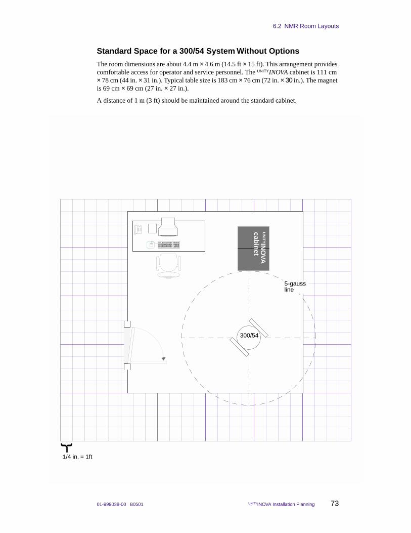
6.2 NMR Room Layouts
01-999038-00 B0501 UNITYINOVA Installation Planning 73
Standard Space for a 300/54 System Without Options
The room dimensions are about 4.4 m × 4.6 m (14.5 ft × 15 ft). This arrangement provides comfortable access for operator and service personnel. The UNITYINOVA cabinet is 111 cm × 78 cm (44 in. × 31 in.). Typical table size is 183 cm × 76 cm (72 in. × 30 in.). The magnet is 69 cm × 69 cm (27 in. × 27 in.).
A distance of 1 m (3 ft) should be maintained around the standard cabinet.
{
UN
ITYIN
OVA
cabin
et
1/4 in. = 1ft
300/54
5-gaussline
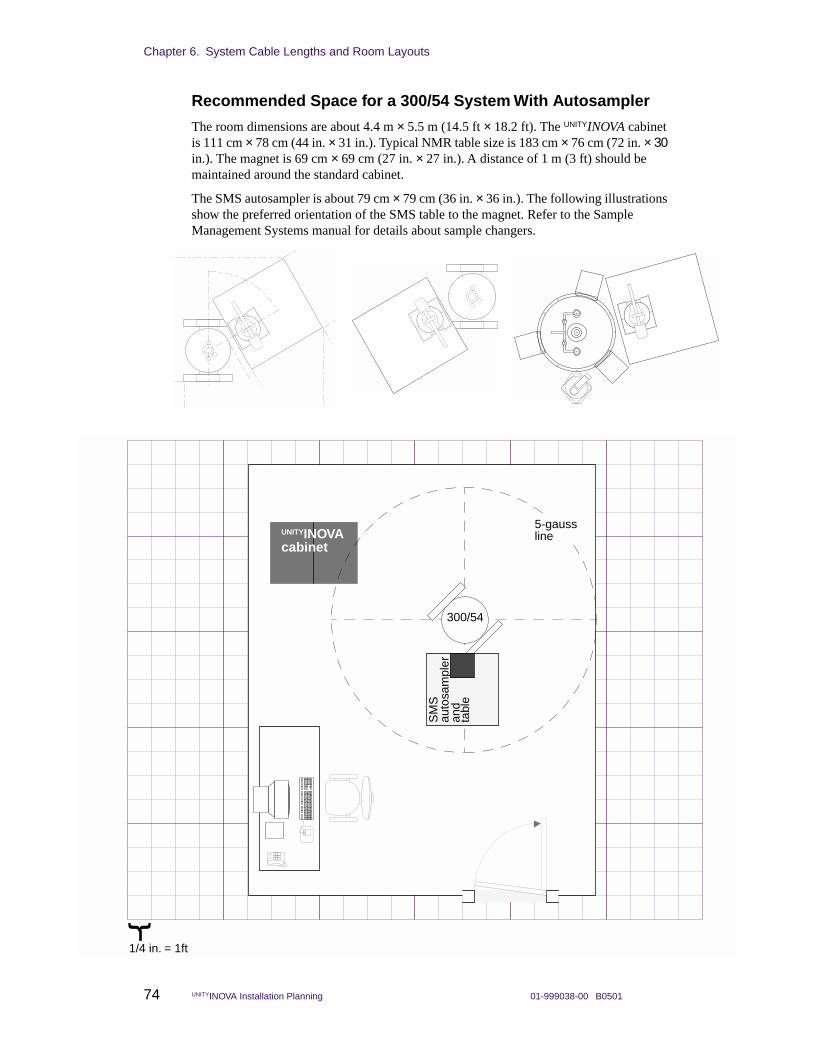
Chapter 6. System Cable Lengths and Room Layouts
74 UNITYINOVA Installation Planning 01-999038-00 B0501
Recommended Space for a 300/54 System With Autosampler
The room dimensions are about 4.4 m × 5.5 m (14.5 ft × 18.2 ft). The UNITYINOVA cabinet is 111 cm × 78 cm (44 in. × 31 in.). Typical NMR table size is 183 cm × 76 cm (72 in. × 30 in.). The magnet is 69 cm × 69 cm (27 in. × 27 in.). A distance of 1 m (3 ft) should be maintained around the standard cabinet.
The SMS autosampler is about 79 cm × 79 cm (36 in. × 36 in.). The following illustrations show the preferred orientation of the SMS table to the magnet. Refer to the Sample Management Systems manual for details about sample changers.
{
UNITYINOVAcabinet
1/4 in. = 1ft
300/54
5-gaussline
SM
S
auto
sam
pler
and
tabl
e
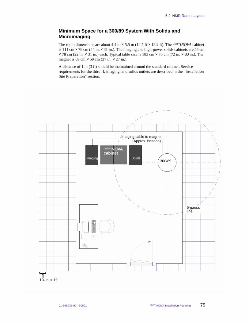
6.2 NMR Room Layouts
01-999038-00 B0501 UNITYINOVA Installation Planning 75
Minimum Space for a 300/89 System With Solids and Microimaging
The room dimensions are about 4.4 m × 5.5 m (14.5 ft × 18.2 ft). The UNITYINOVA cabinet is 111 cm × 78 cm (44 in. × 31 in.). The imaging and high-power solids cabinets are 55 cm × 78 cm (22 in. × 31 in.) each. Typical table size is 183 cm × 76 cm (72 in. × 30 in.). The magnet is 69 cm × 69 cm (27 in. × 27 in.).
A distance of 1 m (3 ft) should be maintained around the standard cabinet. Service requirements for the third rf, imaging, and solids outlets are described in the “Installation Site Preparation” section.
{
Imaging Solids
Imaging cable to magnet(Approx. location)
UNITYINOVAcabinet
1/4 in. = 1ft
300/89
5-gaussline
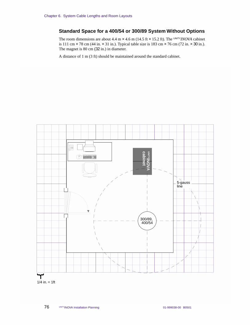
Chapter 6. System Cable Lengths and Room Layouts
76 UNITYINOVA Installation Planning 01-999038-00 B0501
Standard Space for a 400/54 or 300/89 System Without Options
The room dimensions are about 4.4 m × 4.6 m (14.5 ft × 15.2 ft). The UNITYINOVA cabinet is 111 cm × 78 cm (44 in. × 31 in.). Typical table size is 183 cm × 76 cm (72 in. × 30 in.). The magnet is 80 cm (32 in.) in diameter.
A distance of 1 m (3 ft) should be maintained around the standard cabinet.
{
UN
ITYIN
OVA
cabin
et
1/4 in. = 1ft
300/89,
5-gaussline
400/54
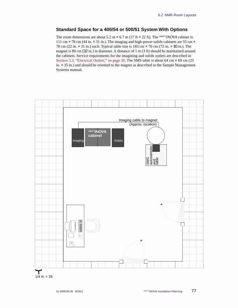
6.2 NMR Room Layouts
01-999038-00 B0501 UNITYINOVA Installation Planning 77
Standard Space for a 400/54 or 500/51 System With Options
The room dimensions are about 5.2 m × 6.7 m (17 ft × 22 ft). The UNITYINOVA cabinet is 111 cm × 78 cm (44 in. × 31 in.). The imaging and high-power solids cabinets are 55 cm × 78 cm (22 in. × 31 in.) each. Typical table size is 183 cm × 76 cm (72 in. × 30 in.). The magnet is 80 cm (32 in.) in diameter. A distance of 1 m (3 ft) should be maintained around the cabinets. Service requirements for the imagining and solids outlets are described in Section 3.3, “Electrical Outlets,” on page 36. The SMS table is about 64 cm × 69 cm (25 in. × 35 in.) and should be oriented to the magnet as described in the Sample Management Systems manual.
{
Imaging Solids
Imaging cable to magnet(Approx. location)
SM
S
auto
sam
pler
and
tabl
e
UNITYINOVAcabinet
1/4 in. = 1ft
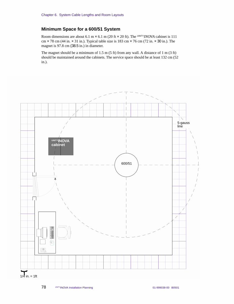
Chapter 6. System Cable Lengths and Room Layouts
78 UNITYINOVA Installation Planning 01-999038-00 B0501
Minimum Space for a 600/51 System
Room dimensions are about 6.1 m × 6.1 m (20 ft × 20 ft). The UNITYINOVA cabinet is 111 cm × 78 cm (44 in. × 31 in.). Typical table size is 183 cm × 76 cm (72 in. × 30 in.). The magnet is 97.8 cm (38.5 in.) in diameter.
The magnet should be a minimum of 1.5 m (5 ft) from any wall. A distance of 1 m (3 ft) should be maintained around the cabinets. The service space should be at least 132 cm (52 in.).
{
UNITYINOVAcabinet
1/4 in. = 1ft
600/51
5-gaussline
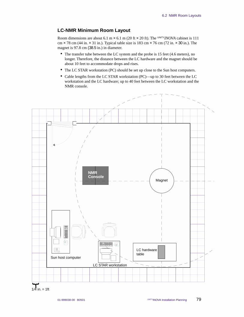
6.2 NMR Room Layouts
01-999038-00 B0501 UNITYINOVA Installation Planning 79
LC-NMR Minimum Room Layout
Room dimensions are about 6.1 m × 6.1 m (20 ft × 20 ft). The UNITYINOVA cabinet is 111 cm × 78 cm (44 in. × 31 in.). Typical table size is 183 cm × 76 cm (72 in. × 30 in.). The magnet is 97.8 cm (38.5 in.) in diameter.
• The transfer tube between the LC system and the probe is 15 feet (4.6 meters), no longer. Therefore, the distance between the LC hardware and the magnet should be about 10 feet to accommodate drops and rises.
• The LC STAR workstation (PC) should be set up close to the Sun host computers.
• Cable lengths from the LC STAR workstation (PC)—up to 30 feet between the LC workstation and the LC hardware; up to 40 feet between the LC workstation and the NMR console.
NMR
LC hardwaretable
LC STAR workstation
Sun host computer
ConsoleMagnet
{
1/4 in. = 1ft
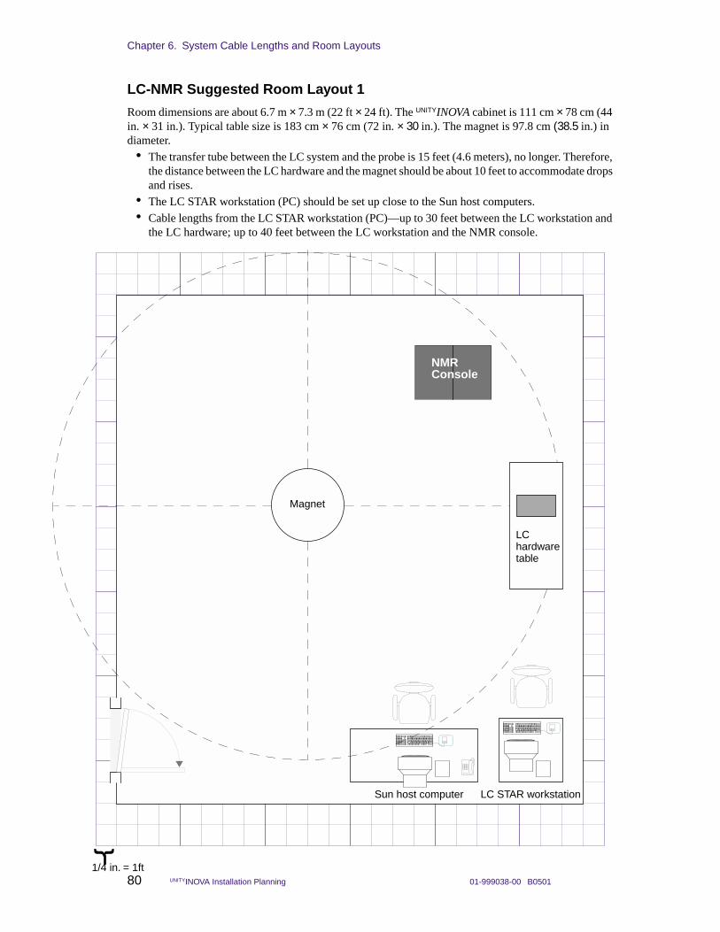
Chapter 6. System Cable Lengths and Room Layouts
80 UNITYINOVA Installation Planning 01-999038-00 B0501
LC-NMR Suggested Room Layout 1
Room dimensions are about 6.7 m × 7.3 m (22 ft × 24 ft). The UNITYINOVA cabinet is 111 cm × 78 cm (44 in. × 31 in.). Typical table size is 183 cm × 76 cm (72 in. × 30 in.). The magnet is 97.8 cm (38.5 in.) in diameter.
• The transfer tube between the LC system and the probe is 15 feet (4.6 meters), no longer. Therefore, the distance between the LC hardware and the magnet should be about 10 feet to accommodate drops and rises.
• The LC STAR workstation (PC) should be set up close to the Sun host computers.
• Cable lengths from the LC STAR workstation (PC)—up to 30 feet between the LC workstation and the LC hardware; up to 40 feet between the LC workstation and the NMR console.
NMRConsole
LC hardwaretable
LC STAR workstationSun host computer
Magnet
{
1/4 in. = 1ft
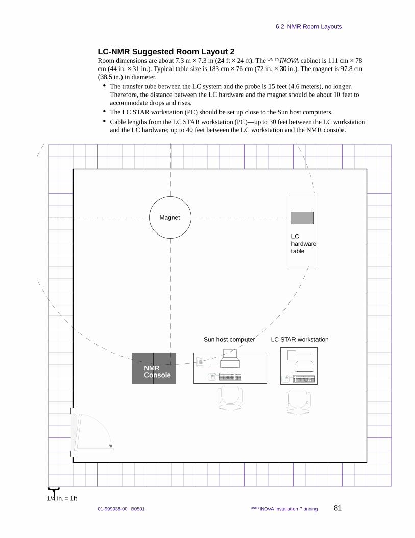
6.2 NMR Room Layouts
01-999038-00 B0501 UNITYINOVA Installation Planning 81
LC-NMR Suggested Room Layout 2Room dimensions are about 7.3 m × 7.3 m (24 ft × 24 ft). The UNITYINOVA cabinet is 111 cm × 78 cm (44 in. × 31 in.). Typical table size is 183 cm × 76 cm (72 in. × 30 in.). The magnet is 97.8 cm (38.5 in.) in diameter.
• The transfer tube between the LC system and the probe is 15 feet (4.6 meters), no longer. Therefore, the distance between the LC hardware and the magnet should be about 10 feet to accommodate drops and rises.
• The LC STAR workstation (PC) should be set up close to the Sun host computers.
• Cable lengths from the LC STAR workstation (PC)—up to 30 feet between the LC workstation and the LC hardware; up to 40 feet between the LC workstation and the NMR console.
NMRConsole
LC hardwaretable
LC STAR workstationSun host computer
Magnet
{
1/4 in. = 1ft
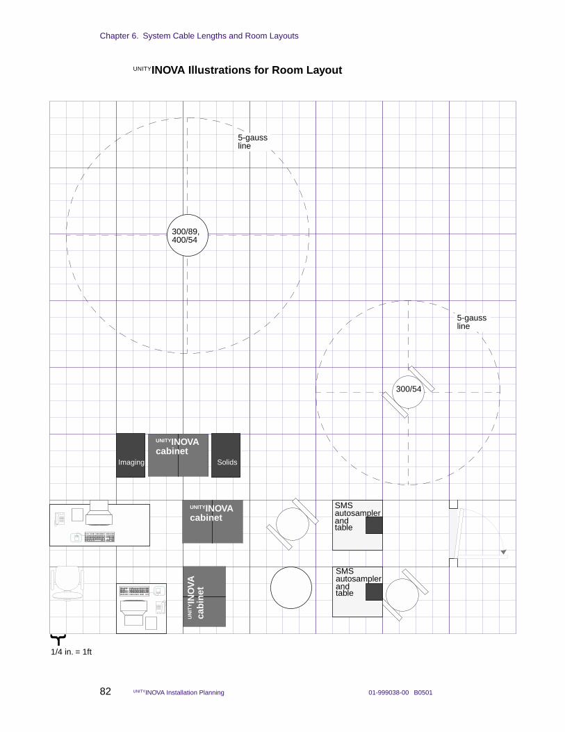
Chapter 6. System Cable Lengths and Room Layouts
82 UNITYINOVA Installation Planning 01-999038-00 B0501
UNITYINOVA Illustrations for Room Layout
GEMINI 2000Cabinet
GE
MIN
I 200
0C
abin
et
SMS autosamplerandtable
SMS autosamplerandtable
{
Imaging Solids
UNITYINOVAcabinet
UNITYINOVAcabinet
UN
ITYIN
OVA
cab
inet
1/4 in. = 1ft
300/89,
300/54
5-gaussline
400/54
5-gaussline
6.2 NMR Room Layouts
01-999038-00 B0501 UNITYINOVA Installation Planning 83
Blank Grid for Room Layout{
1/4 in. = 1ft

Chapter 6. System Cable Lengths and Room Layouts
84 UNITYINOVA Installation Planning 01-999038-00 B0501
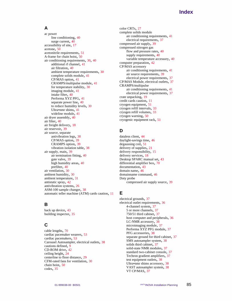
01-999038-00 B0501 UNITYINOVA Installation Planning 85
IndexIndex
Aac power
line conditioning, 40surge current, 40
accessibility of site, 17acetone, 50acetonitrile requirements, 51A-frame for chain hoist, 50air conditioning requirements, 30, 40
additional rf channel, 41air filtration, 40ambient temperature requirements, 30complete solids module, 41CP/MAS option, 41CRAMPS/multipulse module, 41for temperature stability, 30imaging module, 41intake filter, 40Performa XYZ PFG, 41separate power line, 40to reduce humidity levels, 30Ultra•nmr shims, 41wideline module, 41
air dryer assembly, 40air filter, 40air freight delivery, 18air reservoir, 39air source, separate
antivibration legs, 38CP/MAS option, 39CRAMPS option, 39vibration isolation table, 38
air supply, main, 39air termination fitting, 40gate valve, 39high humidity areas, 40prefilter, 40
air ventilation, 30ambient humidity, 30ambient temperature, 31antistatic spray, 42antivibration systems, 26ASM-100 sample changer, 38automatic teller machine (ATM) cards caution, 11
Bback up device, 43building inspector, 35
Ccable lengths, 70cardiac pacemaker wearers, 53cardiac pacemakers, 53Carousel Autosampler, electrical outlets, 38cautions defined, 9CD-ROM drive, 42ceiling height, 24centerline to floor distance, 29CFM-rated fans for ventilation, 30chain hoist, 50codes, 35
color CRTs, 27complete solids module
air conditioning requirements, 41electrical requirements, 37
compressed air supply, 39compressed nitrogen gas
flow and pressure rates, 40supply requirements, 40variable temperature accessory, 40
computer preparation, 42CP/MAS accessory
air conditioning requirements, 41air source requirements, 39electrical power requirements, 37
CP/MAS Module, electrical outlets, 37CRAMPS/multipulse
air conditioning requirements, 41electrical power requirements, 37
crate unpacking, 19credit cards caution, 11cryogen equipment, 51cryogen refill intervals, 33cryogen refill volumes, 33cryogen warning, 50cryogenic equipment rack, 51
Ddataless client, 44daylight-savings time, 46degaussing coil, 51delivery of supplies, 21delivery responsibility, 15delivery services, 18Desktop SPARC manual set, 43differential amplifier box, 70documentation, 43domain name, 46domainname command, 46Doty probe
compressed air supply source, 39
Eelectrical grounds, 37electrical outlet requirements, 36
4-channel system, 375 or more channels, 37750/51 third cabinet, 37host computer and peripherals, 36LC-NMR accessory, 38microimaging module, 37Performa XYZ PFG module, 37PFG accessories, 38separate ground for third cabinet, 37SMS autosampler system, 38solids third cabinet, 37solid-state NMR modules, 37standard two-cabinet console, 37Techron gradient amplifiers, 37test equipment outlets, 38Ultra•nmr shims accessory, 38VAST autosampler system, 38VT CP/MAS, 37
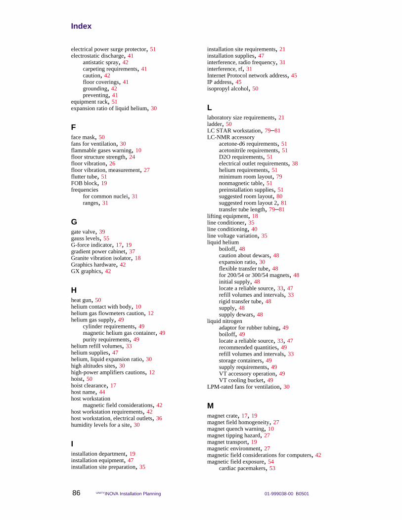
Index
86 UNITYINOVA Installation Planning 01-999038-00 B0501
electrical power surge protector, 51electrostatic discharge, 41
antistatic spray, 42carpeting requirements, 41caution, 42floor coverings, 41grounding, 42preventing, 41
equipment rack, 51expansion ratio of liquid helium, 30
Fface mask, 50fans for ventilation, 30flammable gases warning, 10floor structure strength, 24floor vibration, 26floor vibration, measurement, 27flutter tube, 51FOB block, 19frequencies
for common nuclei, 31ranges, 31
Ggate valve, 39gauss levels, 55G-force indicator, 17, 19gradient power cabinet, 37Granite vibration isolator, 18Graphics hardware, 42GX graphics, 42
Hheat gun, 50helium contact with body, 10helium gas flowmeters caution, 12helium gas supply, 49
cylinder requirements, 49magnetic helium gas container, 49purity requirements, 49
helium refill volumes, 33helium supplies, 47helium, liquid expansion ratio, 30high altitudes sites, 30high-power amplifiers cautions, 12hoist, 50hoist clearance, 17host name, 44host workstation
magnetic field considerations, 42host workstation requirements, 42host workstation, electrical outlets, 36humidity levels for a site, 30
Iinstallation department, 19installation equipment, 47installation site preparation, 35
installation site requirements, 21installation supplies, 47interference, radio frequency, 31interference, rf, 31Internet Protocol network address, 45IP address, 45isopropyl alcohol, 50
Llaboratory size requirements, 21ladder, 50LC STAR workstation, 79–81LC-NMR accessory
acetone-d6 requirements, 51acetonitrile requirements, 51D2O requirements, 51electrical outlet requirements, 38helium requirements, 51minimum room layout, 79nonmagnetic table, 51preinstallation supplies, 51suggested room layout, 80suggested room layout 2, 81transfer tube length, 79–81
lifting equipment, 18line conditioner, 35line conditioning, 40line voltage variation, 35liquid helium
boiloff, 48caution about dewars, 48expansion ratio, 30flexible transfer tube, 48for 200/54 or 300/54 magnets, 48initial supply, 48locate a reliable source, 33, 47refill volumes and intervals, 33rigid transfer tube, 48supply, 48supply dewars, 48
liquid nitrogenadaptor for rubber tubing, 49boiloff, 49locate a reliable source, 33, 47recommended quantities, 49refill volumes and intervals, 33storage containers, 49supply requirements, 49VT accessory operation, 49VT cooling bucket, 49
LPM-rated fans for ventilation, 30
Mmagnet crate, 17, 19magnet field homogeneity, 27magnet quench warning, 10magnet tipping hazard, 27magnet transport, 19magnetic environment, 27magnetic field considerations for computers, 42magnetic field exposure, 54
cardiac pacemakers, 53
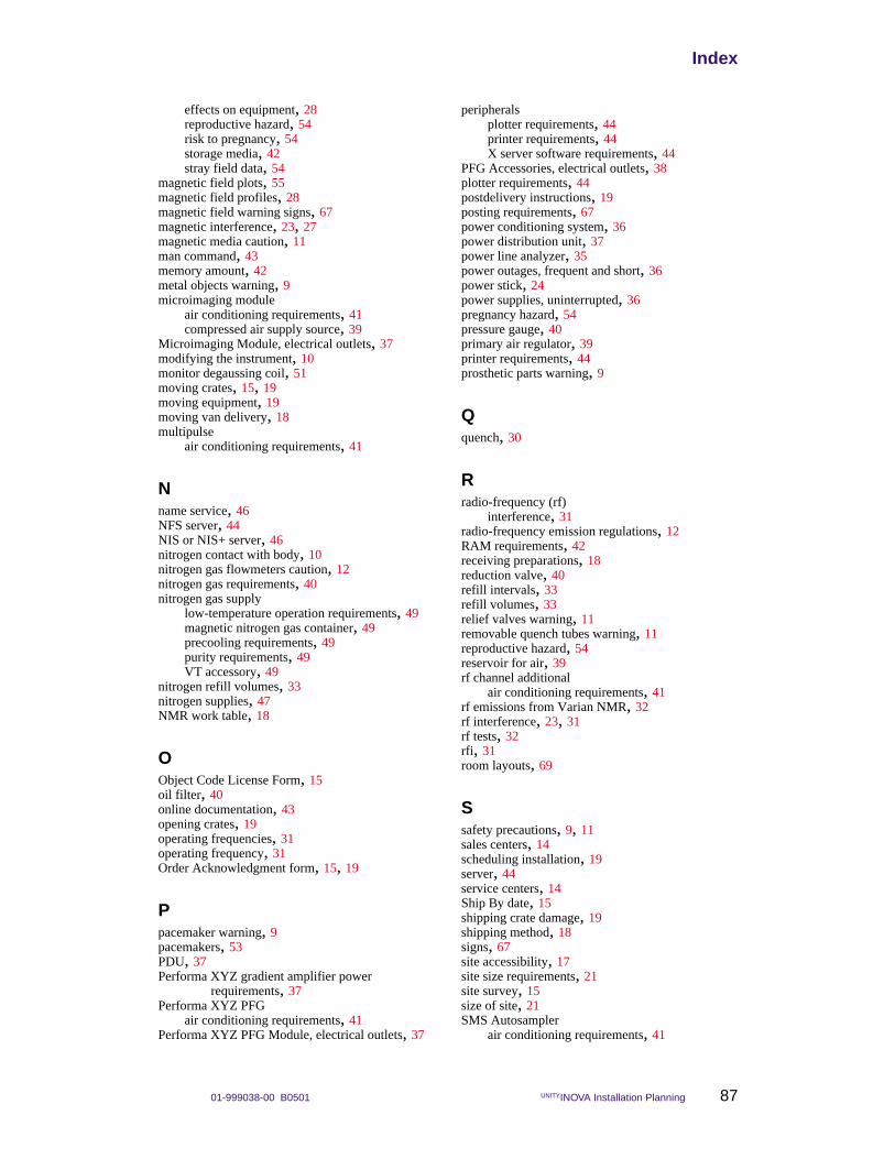
01-999038-00 B0501 UNITYINOVA Installation Planning 87
Index
effects on equipment, 28reproductive hazard, 54risk to pregnancy, 54storage media, 42stray field data, 54
magnetic field plots, 55magnetic field profiles, 28magnetic field warning signs, 67magnetic interference, 23, 27magnetic media caution, 11man command, 43memory amount, 42metal objects warning, 9microimaging module
air conditioning requirements, 41compressed air supply source, 39
Microimaging Module, electrical outlets, 37modifying the instrument, 10monitor degaussing coil, 51moving crates, 15, 19moving equipment, 19moving van delivery, 18multipulse
air conditioning requirements, 41
Nname service, 46NFS server, 44NIS or NIS+ server, 46nitrogen contact with body, 10nitrogen gas flowmeters caution, 12nitrogen gas requirements, 40nitrogen gas supply
low-temperature operation requirements, 49magnetic nitrogen gas container, 49precooling requirements, 49purity requirements, 49VT accessory, 49
nitrogen refill volumes, 33nitrogen supplies, 47NMR work table, 18
OObject Code License Form, 15oil filter, 40online documentation, 43opening crates, 19operating frequencies, 31operating frequency, 31Order Acknowledgment form, 15, 19
Ppacemaker warning, 9pacemakers, 53PDU, 37Performa XYZ gradient amplifier power
requirements, 37Performa XYZ PFG
air conditioning requirements, 41Performa XYZ PFG Module, electrical outlets, 37
peripheralsplotter requirements, 44printer requirements, 44X server software requirements, 44
PFG Accessories, electrical outlets, 38plotter requirements, 44postdelivery instructions, 19posting requirements, 67power conditioning system, 36power distribution unit, 37power line analyzer, 35power outages, frequent and short, 36power stick, 24power supplies, uninterrupted, 36pregnancy hazard, 54pressure gauge, 40primary air regulator, 39printer requirements, 44prosthetic parts warning, 9
Qquench, 30
Rradio-frequency (rf)
interference, 31radio-frequency emission regulations, 12RAM requirements, 42receiving preparations, 18reduction valve, 40refill intervals, 33refill volumes, 33relief valves warning, 11removable quench tubes warning, 11reproductive hazard, 54reservoir for air, 39rf channel additional
air conditioning requirements, 41rf emissions from Varian NMR, 32rf interference, 23, 31rf tests, 32rfi, 31room layouts, 69
Ssafety precautions, 9, 11sales centers, 14scheduling installation, 19server, 44service centers, 14Ship By date, 15shipping crate damage, 19shipping method, 18signs, 67site accessibility, 17site size requirements, 21site survey, 15size of site, 21SMS Autosampler
air conditioning requirements, 41
Index
88 UNITYINOVA Installation Planning 01-999038-00 B0501
SMS Autosampler robot, 18SMS Autosampler table, 18SMS Autosampler, electrical outlets, 38Solaris
CD-ROM, 43collecting system and network information, 44
Solaris operating system software, 42solids high-power amplifiers caution, 12solids modules, 37Solid-State NMR Modules Cabinet, electrical
outlets, 37solvents, 50spectrometer frequency ranges, 31stand alone, 44step-down transformer, 37–38stingers, 51stray field plots, 29, 53, 55streaming tape cartridge, 42structural floor loading rating, 24subnet mask, 46sucrose requirements, 51Sun peripherals, 42Sun workstation, 42Sun workstations, 42sunlight, 30supplies, 47supply dewars, 21supporting the magnet, 27surge current, 40surge protection, 36, 51
TTechron units, 37temperature stability, 30thermal gloves, 50third rf channel
compressed air supply source, 39tip-and-tell indicator, 17, 19transfer of ownership, 19transfer tube, 24, 51transformer, step-down, 38Tygon tubing, 51
UUltra•nmr shims
air conditioning requirements, 41cable lengths, 70
Ultra•nmr Shims Accessory, electrical outlets, 38uname -n command, 44uncrating system, 18upper barrel warning, 10UPS systems, 36
Vvan delivery, 18Varian sales and service centers, 14VAST Autosampler, electrical outlets, 38ventilation, 30vertical magnetic fields, 28vibration in floor, 26
vibration in floor, measurement, 27vibration table, 39VME card cage, 37VNMR and Solaris Software Installation Manual, 43voltage variations, 35volumetric flasks requirements, 51VT CP/MAS Module, electrical outlets, 37VT experiment warning, 10
Wwarning signs, 67warnings defined, 9waste container, 51waste container cover, 51wideline module
air conditioning requirements, 41compressed air supply source, 39electrical power requirements, 37
workstation preparation, 42world time zones, 46
XX server software requirements, 44XYZ PFG Module, electrical outlets, 37
Yypcat command, 46ypwhich command, 46