Embed Size (px)
Citation preview
Volume6,Number2 107
INNOVATIVE FAÇADES Lightweight and Thin Systems with High Inertia
for the Thermal Comfort Application in Office Buildings in Southern Europe
Monica Rossi1
KEYWORDSbuilding envelope, thermal comfort, thermal inertia, dry construction
1PhD, Università degli Studi di Camerino, School of Architecture and Design “Eduardo Vittoria,” via Lungo Castellano, 63100 Ascoli Piceno, Italy, [email protected].
ABSTRACTThis research demonstrates that lightweight, thin façade systems with innovative materials can combine a higher thermal inertia with a lower energy demand for heating and cooling as compared to massive façades. It is therefore very possible to use innovative light materials (originally developed in and for Central Europe) also in Southern Europe, where the main problem is the energy demand for cooling in summer (in contrast to the energy demand for heating in northern latitudes). Three of those systems were selected and investigated for three different climatic conditions in middle latitudes with respect not only to static energy performance parameters imposed by the Italian legislation (thermal transmittance U and superficial mass MS), but also checking two dynamic energy performance parameters defined particularly for non massive structures (phase delay fa and decrement factor φ). Additionally a recently introduced by European standard UNI-EN-ISO-13786 parameter (periodic thermal transmittance Yia) was considered. Verification of the energy performance of the façade systems was performed using thermodynamic simulations. The results are:
• Development and application of an experimental / simulation procedure for the evaluation of the thermal performance of façade systems in use (annual energy demand: [kWh], costs [€] and .CO2 produced [kg]).
• Demonstration that energy performance of new lightweight systems is better than the one of a traditional Italian reference façade system with high MS.
• Proposal of possibilities for improving the analyzed façade systems with respect to their application in middle latitudes.
• Development of design criteria for the application of the analyzed façades in three climatic zones in Italy.
RESEA
RC
H
108 Journal of Green Building
INTRODUCTIONIn the world of architecture and building, sustainable development is about reducing energy demand and CO2 emission during the entire life cycle of buildings—construction, use, main-tenance and demolishing—including the life cycle assessment (LCA) of all materials, products and components used. Since the tested materials are very innovative, it was not possible to obtain information from manufacturers on the energy demand and the CO2 emission during the manufacturing process. Therefore this research focuses only on the reduction of energy demand and consumption during the building use and, in particular, the energy demand for heating and cooling as a function of the performance of building envelopes.
Considering the building envelope as a dynamic interface between the surrounding and the internal environment, its primary role is to contribute to guarantee internal comfort, whilst limiting the use of non renewable energy sources. As a result, this research has identified a number of building façade systems that can be assembled off-site and combine their light-weight structure with a high energy performance, particularly with respect to reduced thermal transmittance and increased thermal inertia.
Following a detailed analysis of the products that have been developed in Central Europe in recent years, three groups of innovative products—not yet available or applied in South-ern Europe (middle latitudes)—have been identified with respect to satisfying those needs / requirements: VIP (Vacuum Insulation Panels), TIM (Transparent Insulation Materials) and PCM (Phase Changing Materials) (Pfundstein 2007).
These products in fact show interesting energetic characteristics, which are difficult to be found in other materials used in the construction of building façades across Southern Europe:
• VIP can combine a high thermal resistance with extremely reduced weight and thickness, due to their evacuated condition (Cremers 2007);
• TIM also feature a high thermal resistance combined with reduced weight and thickness. If attached to an opaque wall, they can greatly increase its thermal storage capacity (Kerschberger, 1996);
• PCM can greatly increase the thermal inertia of a non-massive structure independent of their thickness due to their capacity of changing phase.
CASE STUDIES AND INNOVATIVE FAÇADE SYSTEMSWith the intention to evaluate the applicability of those products in Southern Europe, a num-ber of existing central European buildings, characterised by the use of VIP, TIM or PCM, were selected.
As a result of the analysis of their performance (monitored for at least one year), the build-ings identified to be particularly innovative and energy efficient are:
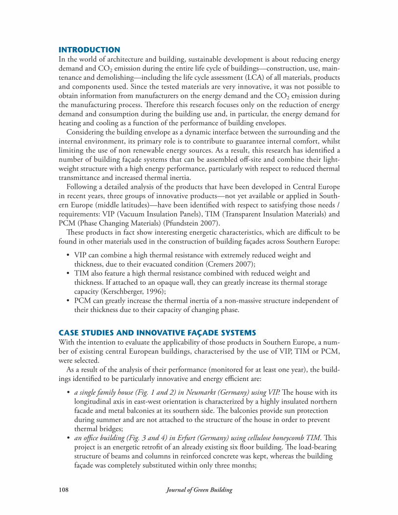
• a single family house (Fig. 1 and 2) in Neumarkt (Germany) using VIP. The house with its longitudinal axis in east-west orientation is characterized by a highly insulated northern facade and metal balconies at its southern side. The balconies provide sun protection during summer and are not attached to the structure of the house in order to prevent thermal bridges;
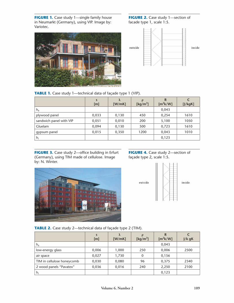
• an office building (Fig. 3 and 4) in Erfurt (Germany) using cellulose honeycomb TIM. This project is an energetic retrofit of an already existing six floor building. The load-bearing structure of beams and columns in reinforced concrete was kept, whereas the building façade was completely substituted within only three months;
Volume6,Number2 109
FIGURE 1. Case study 1—single family house in Neumarkt (Germany), using VIP. Image by: Variotec.
FIGURE 2. Case study 1—section of facade type 1, scale 1:5.
TABLE 1. Case study 1—technical data of façade type 1 (VIP).
s [m]
λ[W/mK]
ρ[kg/m3]
R [m2k/W]
C [J/kgK]
he 0,043
plywood panel 0,033 0,130 450 0,254 1610
sandwich panel with VIP 0,051 0,010 200 5,100 1050
Gluelam 0,094 0,130 500 0,723 1610
gypsum panel 0,015 0,350 1200 0,043 1010
hi 0,123
FIGURE 4. Case study 2—section of façade type 2, scale 1:5.
TABLE 2. Case study 2—technical data of façade type 2 (TIM).
s [m]
λ[W/mK]
ρ[kg/m3]
R [m2k/W]
C J/k gK
he 0,043
low-energy glass 0,006 1,000 250 0,006 2500
air space 0,027 1,730 0 0,156
TIM in cellulose honeycomb 0,030 0,080 96 0,375 2340
2 wood panels “Pavatex” 0,036 0,016 240 2,250 2100
hi 0,123
FIGURE 3. Case study 2—office building in Erfurt (Germany), using TIM made of cellulose. Image by: N. Winter.
110 Journal of Green Building
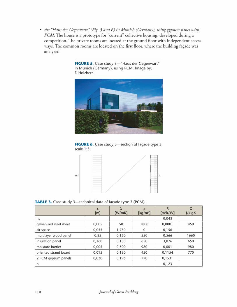
• the “Haus der Gegenwart” (Fig. 5 and 6) in Munich (Germany), using gypsum panel with PCM. The house is a prototype for “current” collective housing, developed during a competition. The private rooms are located at the ground floor with independent access ways. The common rooms are located on the first floor, where the building façade was analyzed.
TABLE 3. Case study 3—technical data of façade type 3 (PCM).
s [m]
λ[W/mK]
ρ[kg/m3]
R [m2k/W]
C J/k gK
he 0,043
galvanized steel sheet 0,005 50 7800 0,0001 450
air space 0,055 1,730 0 0,156
multilayer wood panel 0,85 0,150 550 0,566 1660
insulation panel 0,160 0,130 650 3,076 650
moisture barrier 0,005 0,500 980 0,001 980
oriented strand board 0,015 0,130 450 0,1154 770
2 PCM gypsum panels 0,030 0,196 770 0,1531
hi 0,123
FIGURE 5. Case study 3—“Haus der Gegenwart” in Munich (Germany), using PCM. Image by: F. Holzherr.
FIGURE 6. Case study 3—section of façade type 3, scale 1:5.
Volume6,Number2 111
PROCEDURE FOR THE EVALUATION OF THE THERMAL PERFORMANCE IN USE OF SELECTED FAÇADE SYSTEMSIn order to verify the potential application of the selected building façade systems in middle latitudes, the systems were evaluated with respect to the current Italian design regulations (Imperadori 2006). This standard defines an upper limit for the thermal transmittance of a façade based on the climatic zone where the building is located and imposes a minimum “superficial mass” [MS in kg/m2] for the external vertical surfaces. According to the Italian design regulations (Dlgs. 311/2006, 2007), thermal transmittance [U] has to be lower than 0,33 W/m2K for the coldest climate zone in Italy and the superficial mass [MS] has to exceed 230 kg/m2 for the warmest climate zone. In case the value for MS falls below this limit, an experimental verification is necessary to prove that the thermal inertia is equivalent to that of a façade characterized by the required values. As the selected building façade systems show a very low value of thermal transmittance compared to the design standard—yet their superfi-cial mass is lower than the minimum required (Tables 1, 2 and 3)—it has been necessary to simulate their thermal inertia.
Façade type 1: U = 0,120 W/m2K, Ms = 90 kg/m2.Façade type 2: U = 0,330 W/m2K, Ms = 16 kg/m2.Façade type 3: U = 0,230 W/m2K, Ms = 135,34 kg/m2.
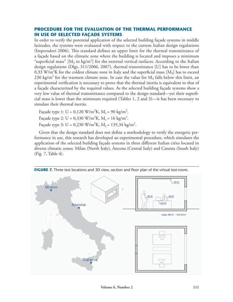
Given that the design standard does not define a methodology to verify the energetic per-formance in use, this research has developed an experimental procedure, which simulates the application of the selected building façade systems in three different Italian cities located in diverse climatic zones: Milan (North Italy), Ancona (Central Italy) and Catania (South Italy) (Fig. 7, Table 4).
FIGURE 7. Three test locations and 3D view, section and floor plan of the virtual test-room.
112 Journal of Green Building
The energy performance for each of the three selected façade systems has been verified by means of thermodynamic simulations using the software package “Energy Plus” applied to a virtual test room in those three cities. The virtual test room has a floor surface of 22,5 m2
and a height of 3 m. The room has been simulated as an office space (internal thermal load of 380 W) south-oriented and with a window-to-wall ratio of 30% (Fig. 7).
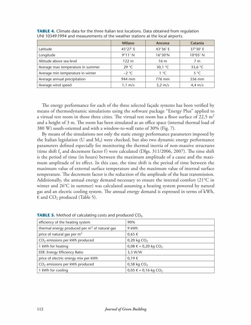
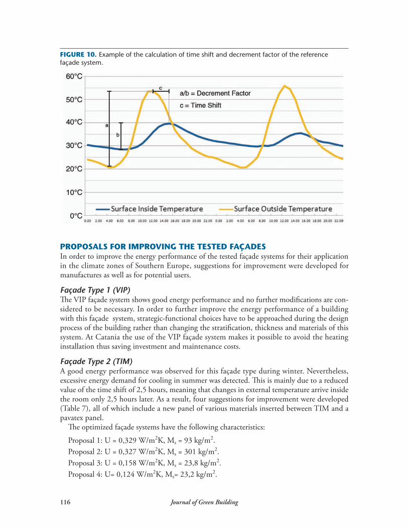
By means of the simulations not only the static energy performance parameters imposed by the Italian legislation (U and MS) were checked, but also two dynamic energy performance parameters defined especially for monitoring the thermal inertia of non-massive structures (time shift fa and decrement factor f ) were calculated (Dlgs. 311/2006, 2007). The time shift is the period of time (in hours) between the maximum amplitude of a cause and the maxi-mum amplitude of its effect. In this case, the time shift is the period of time between the maximum value of external surface temperature and the maximum value of internal surface temperature. The decrement factor is the reduction of the amplitude of the heat transmission. Additionally, the annual energy demand necessary to ensure the internal comfort (21°C in winter and 26°C in summer) was calculated assuming a heating system powered by natural gas and an electric cooling system. The annual energy demand is expressed in terms of kWh, € and CO2 produced (Table 5).
TABLE 4. Climate data for the three Italian test locations. Data obtained from regulation UNI 10349:1994 and measurements of the weather stations at the local airports.
Milano Ancona Catania
Latitude 45°27’ E 43°36’ E 37°30’ E
Longitude 9°11’ N 16°30’N 10°05’ N
Altitude above sea level 122 m 16 m 7 m
Average max temperature in summer 29 °C 30,1 °C 33,6 °C
Average min temperature in winter –2 °C 1 °C 5 °C
Average annual precipitation 944 mm 776 mm 556 mm
Average wind speed 1,1 m/s 3,2 m/s 4,4 m/s
TABLE 5. Method of calculating costs and produced CO2.
efficiency of the heating system 90%
thermal energy produced per m3 of natural gas 9 kWh
price of natural gas per m3 0,65 €
CO2 emissions per kWh produced 0,20 kg CO2
1 kWh for heating 0,08 € = 0,20 kg CO2
EER: Energy Efficiency Ratio 3,3 W/W
price of electric energy mix per kWh 0,19 €
CO2 emissions per kWh produced 0,58 kg CO2
1 kWh for cooling 0,05 € = 0,16 kg CO2
Volume6,Number2 113
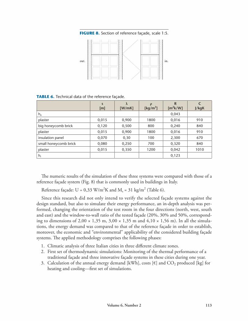
The numeric results of the simulation of these three systems were compared with those of a reference façade system (Fig. 8) that is commonly used in buildings in Italy.
Reference façade: U = 0,33 W/m2K and Ms = 31 kg/m2 (Table 6).
Since this research did not only intend to verify the selected façade systems against the design standard, but also to simulate their energy performance, an in-depth analysis was per-formed, changing the orientation of the test room in the four directions (north, west, south and east) and the window-to-wall ratio of the tested façade (20%, 30% and 50%, correspond-ing to dimensions of 2,00 × 1,35 m, 3,00 × 1,35 m and 4,10 × 1,56 m). In all the simula-tions, the energy demand was compared to that of the reference façade in order to establish, moreover, the economic and “environmental” applicability of the considered building façade systems. The applied methodology comprises the following phases:
1. Climatic analysis of three Italian cities in three different climate zones.2. First set of thermodynamic simulations: Monitoring of the thermal performance of a
traditional façade and three innovative façade systems in these cities during one year.3. Calculation of the annual energy demand [kWh], costs [€] and CO2 produced [kg] for
heating and cooling—first set of simulations.
FIGURE 8. Section of reference façade, scale 1:5.
TABLE 6. Technical data of the reference façade.
s [m]
λ[W/mK]
ρ[kg/m3]
R [m2k/W]
C J/kgK
he 0,043
plaster 0,015 0,900 1800 0,016 910
big honeycomb brick 0,120 0,500 800 0,240 840
plaster 0,015 0,900 1800 0,016 910
insulation panel 0,070 0,30 100 2,300 670
small honeycomb brick 0,080 0,250 700 0,320 840
plaster 0,015 0,350 1200 0,042 1010
hi 0,123
114 Journal of Green Building
4. Evaluation of the simulation results and comparison of the energy performance in use of the reference and the tested façade systems.
5. Second set of thermodynamic simulations—sensitivity analysis:- variation of orientation towards 4 cardinal points,- variation of the window-to-wall ratio for the test system.
6. Calculation of the annual energy demand [kWh], costs [€] and CO2 produced [kg] for heating and cooling—second set of simulations.
7. Evaluation of the results of the second set of simulations.8. Elaboration of proposals for improving the analyzed building façade systems.9. Definition of design guidelines for the application of the analyzed building façade
systems in buildings in Southern Europe (middle latitudes).
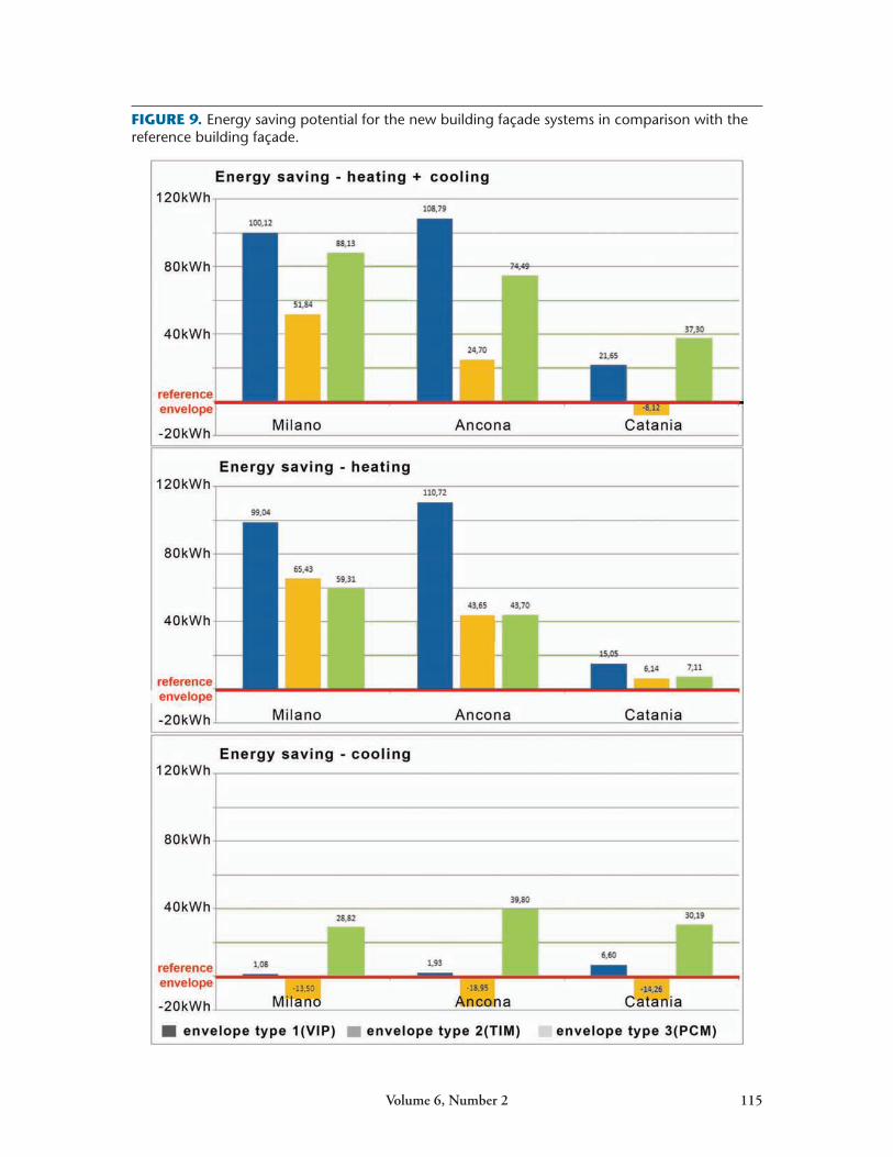
RESULTS OF THE SIMULATIONThe simulations provide the possibility to determine the values of time shift (φ) and decre-ment factor (fa) of the building façades as well as the overall annual energy demand during one year (winter and summer) (Fig. 9).
Reference façade : φ = 7 h, fa =0,42.Façade type 1: φ = 10,62 h; fa = 0,20Façade type 2: φ = 3,46 h; fa = 0,85Façade type 3: φ and fa can’t be determined due to the nature of PCM
The results of the thermodynamic simulations show not only a good thermal performance and energy saving potential for the new building façades, but also their constraints, particu-larly when using those systems in buildings in Southern Europe. The tested building façades showed good results during the course of one year, especially in winter. During the summer period, on the other hand, only a minimum energy saving potential was detected (e.g. façade type 2 in Catania was less efficient than the reference façade ) (Fig. 9).
These results depend on two main factors: The analyzed building façades were developed for the climatic conditions of central Europe (continental climate), where, in contrast to Italy, energy saving mainly means limiting the energy losses towards the surrounding environment during winter period. The used test room is considered to be an office room, meaning that significant internal thermal loads are present. In this case, also building façade systems with a very good energy performance can’t reduce the energy demand for cooling purposes during summer. The use of building façades with a big time shift and decrement factor contributes to limiting the impact of the external thermal load on the internal climate. At the same time, they can’t influence the temperature increase due to the internal thermal load and the solar irradiation through the windows.
Based on the above considerations, two different approaches can be derived to solve these two problems:
• Proposals to improve the analyzed building façade systems for their application in southern Europe.
• Criteria for their application in middle latitudes considering not only the building façade but the entire energy concept of the building in which the façade is used.
Volume6,Number2 115
FIGURE 9. Energy saving potential for the new building façade systems in comparison with the reference building façade.
116 Journal of Green Building
PROPOSALS FOR IMPROVING THE TESTED FAÇADES In order to improve the energy performance of the tested façade systems for their application in the climate zones of Southern Europe, suggestions for improvement were developed for manufactures as well as for potential users.
Façade Type 1 (VIP)The VIP façade system shows good energy performance and no further modifications are con-sidered to be necessary. In order to further improve the energy performance of a building with this façade system, strategic-functional choices have to be approached during the design process of the building rather than changing the stratification, thickness and materials of this system. At Catania the use of the VIP façade system makes it possible to avoid the heating installation thus saving investment and maintenance costs.
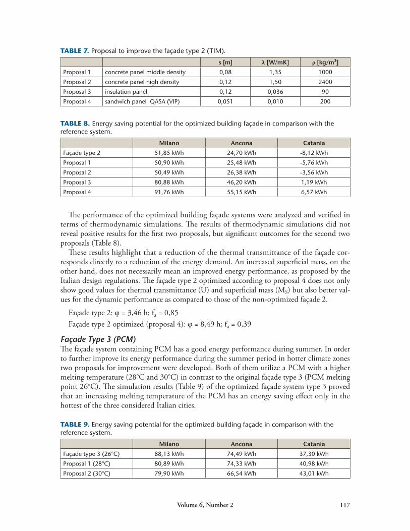
Façade Type 2 (TIM)A good energy performance was observed for this façade type during winter. Nevertheless, excessive energy demand for cooling in summer was detected. This is mainly due to a reduced value of the time shift of 2,5 hours, meaning that changes in external temperature arrive inside the room only 2,5 hours later. As a result, four suggestions for improvement were developed (Table 7), all of which include a new panel of various materials inserted between TIM and a pavatex panel.
The optimized façade systems have the following characteristics:
Proposal 1: U = 0,329 W/m2K, Ms = 93 kg/m2. Proposal 2: U = 0,327 W/m2K, Ms = 301 kg/m2.Proposal 3: U = 0,158 W/m2K, Ms = 23,8 kg/m2.Proposal 4: U= 0,124 W/m2K, Ms= 23,2 kg/m2.
FIGURE 10. Example of the calculation of time shift and decrement factor of the reference façade system.
Volume6,Number2 117
The performance of the optimized building façade systems were analyzed and verified in terms of thermodynamic simulations. The results of thermodynamic simulations did not reveal positive results for the first two proposals, but significant outcomes for the second two proposals (Table 8).
These results highlight that a reduction of the thermal transmittance of the façade cor-responds directly to a reduction of the energy demand. An increased superficial mass, on the other hand, does not necessarily mean an improved energy performance, as proposed by the Italian design regulations. The façade type 2 optimized according to proposal 4 does not only show good values for thermal transmittance (U) and superficial mass (MS) but also better val-ues for the dynamic performance as compared to those of the non-optimized façade 2.
Façade type 2: φ = 3,46 h; fa = 0,85 Façade type 2 optimized (proposal 4): φ = 8,49 h; fa = 0,39
Façade Type 3 (PCM)The façade system containing PCM has a good energy performance during summer. In order to further improve its energy performance during the summer period in hotter climate zones two proposals for improvement were developed. Both of them utilize a PCM with a higher melting temperature (28°C and 30°C) in contrast to the original façade type 3 (PCM melting point 26°C). The simulation results (Table 9) of the optimized façade system type 3 proved that an increasing melting temperature of the PCM has an energy saving effect only in the hottest of the three considered Italian cities.
TABLE 7. Proposal to improve the façade type 2 (TIM).
s [m] λ [W/mK] ρ [kg/m3]
Proposal 1 concrete panel middle density 0,08 1,35 1000
Proposal 2 concrete panel high density 0,12 1,50 2400
Proposal 3 insulation panel 0,12 0,036 90
Proposal 4 sandwich panel QASA (VIP) 0,051 0,010 200
TABLE 8. Energy saving potential for the optimized building façade in comparison with the reference system.
Milano Ancona Catania
Façade type 2 51,85 kWh 24,70 kWh -8,12 kWh
Proposal 1 50,90 kWh 25,48 kWh -5,76 kWh
Proposal 2 50,49 kWh 26,38 kWh -3,56 kWh
Proposal 3 80,88 kWh 46,20 kWh 1,19 kWh
Proposal 4 91,76 kWh 55,15 kWh 6,57 kWh
TABLE 9. Energy saving potential for the optimized building façade in comparison with the reference system.
Milano Ancona Catania
Façade type 3 (26°C) 88,13 kWh 74,49 kWh 37,30 kWh
Proposal 1 (28°C) 80,89 kWh 74,33 kWh 40,98 kWh
Proposal 2 (30°C) 79,90 kWh 66,54 kWh 43,01 kWh
118 Journal of Green Building
The results further demonstrate that using materials that have the ability of changing their thermal performance with changing temperature (PCM) requires a priori accurate climatic analysis of the desired construction site in order to optimize their energy performance. Using PCM without knowing the average daily and monthly temperature—and especially the range of temperature fluctuation during one day—cannot be energetically and economically efficient.
VERIFICATION OF THE OPTIMIZED FACADE SYSTEMS BASED ON NEW NATIONAL AND EUROPEAN STANDARDSDuring the preparation of this research, the issue of energy saving in summer cooling has gained growing international attention. Several new national and European laws were launched to regulate the performance of minimum thermal inertia of building shells and par-ticularly façades.
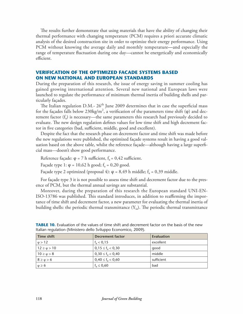
The Italian regulation D.M.- 26th June 2009 determines that in case the superficial mass for the façades falls below 230kg/m2, a verification of the parameters time shift (φ) and dec-rement factor (fa) is necessary—the same parameters this research had previously decided to evaluate. The new design regulation defines values for low time shift and high decrement fac-tor in five categories (bad, sufficient, middle, good and excellent).
Despite the fact that the research phase on decrement factor and time shift was made before the new regulations were published, the optimized façade systems result in having a good val-uation based on the above table, whilst the reference façade—although having a large superfi-cial mass—doesn’t show good performance.
Reference façade: φ = 7 h sufficient, fa = 0,42 sufficient.Façade type 1: φ = 10,62 h good; fa = 0,20 good.Façade type 2 optimized (proposal 4): φ = 8,49 h middle; fa = 0,39 middle.
For façade type 3 it is not possible to assess time shift and decrement factor due to the pres-ence of PCM, but the thermal annual savings are substantial.
Moreover, during the preparation of this research the European standard UNI-EN-ISO-13786 was published. This standard introduces, in addition to reaffirming the impor-tance of time shift and decrement factor, a new parameter for evaluating the thermal inertia of building shells: the periodic thermal transmittance (Yia). The periodic thermal transmittance
TABLE 10. Evaluation of the values of time shift and decrement factor on the basis of the new Italian regulation (Ministero dello Sviluppo Economico, 2009).
Time shift Decrement factor Evaluation
φ > 12 fa < 0,15 excellent
12 ≥ φ > 10 0,15 ≤ fa < 0,30 good
10 ≥ φ > 8 0,30 ≤ fa < 0,40 middle
8 ≥ φ > 6 0,40 ≤ fa < 0,60 sufficient
φ ≥ 6 fa ≤ 0,60 bad
Volume6,Number2 119
is a “complex quantity defined as the complex amplitude of the density of heat flow rate through the surface of the component adjacent to zone m, divided by the complex amplitude of the tem-perature in zone n when the temperature in zone m is held constant” (European Committee for Standardization 2008). The European standard UNI-EN-ISO-13786 defines how to calculate the periodic thermal transmittance whereas Italian Law DPR 59 2th April 2009 defines that for façades a periodic thermal transmittance value must be ≤ 0,12 W/m2K (DPR 59/2009, 2009). Based on this new standard the value of the periodic thermal transmittance has been calculated for the reference façade and the optimized façades.
Reference façade: Yia = 0,1353, not sufficient Façade type 1: Yia = 0,0498, excellent Façade type 2 optimized (proposal 4): Yia = 0,0580 excellent
In façade type 3 it is not possible to assess time shift and decrement factor for the presence of PCM, but the thermal annual savings is substantial.
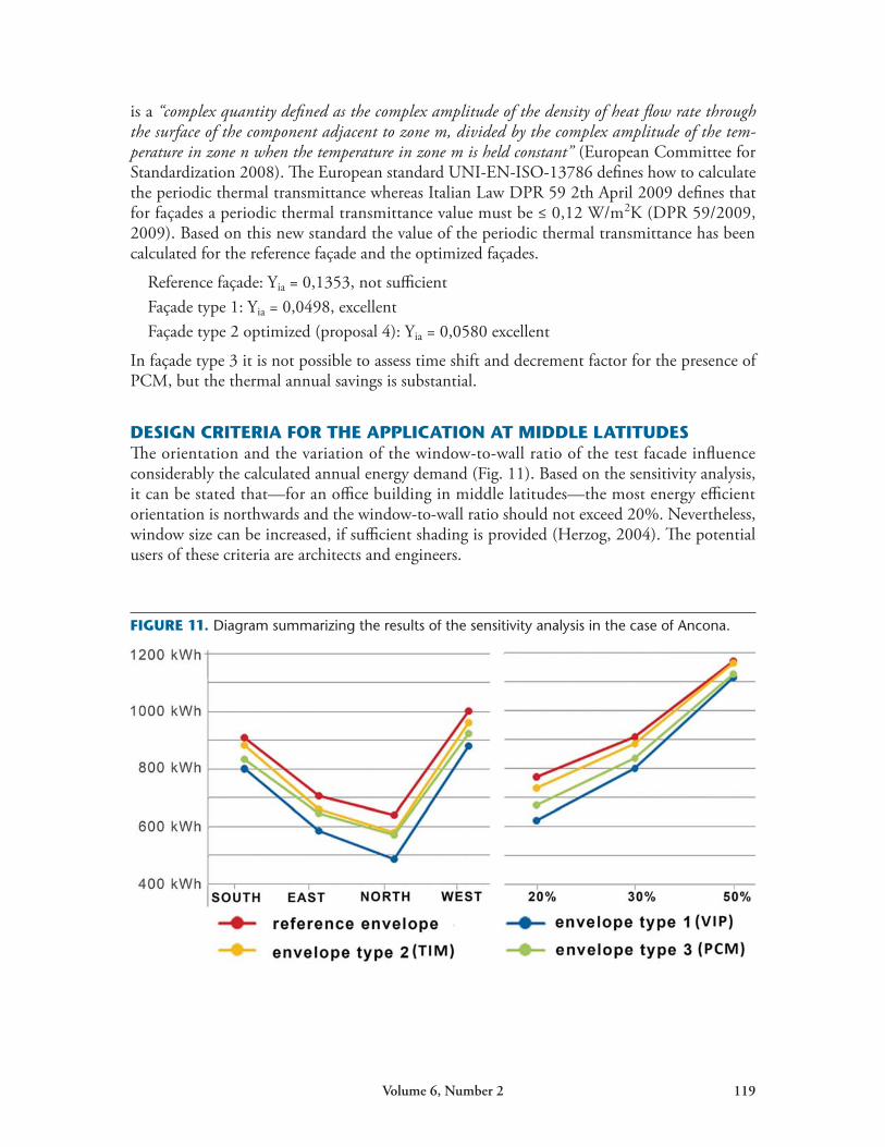
DESIGN CRITERIA FOR THE APPLICATION AT MIDDLE LATITUDESThe orientation and the variation of the window-to-wall ratio of the test facade influence considerably the calculated annual energy demand (Fig. 11). Based on the sensitivity analysis, it can be stated that—for an office building in middle latitudes—the most energy efficient orientation is northwards and the window-to-wall ratio should not exceed 20%. Nevertheless, window size can be increased, if sufficient shading is provided (Herzog, 2004). The potential users of these criteria are architects and engineers.
FIGURE 11. Diagram summarizing the results of the sensitivity analysis in the case of Ancona.
120 Journal of Green Building
CONCLUSION This research has demonstrated that thin non-massive building façades with a reduced super-ficial mass and realized with VIP, TIM or PCM can have a lower annual energy demand com-pared to massive building façades, also if used in middle latitudes, where the main problem is the energy demand for cooling in summer. Furthermore it is possible to reduce the summer energy demand for cooling with simple modifications to the tested façades systems (addition of a layer in the façade type 2 with TIM and increasing melting temperature in the façade type 3 with PCM).
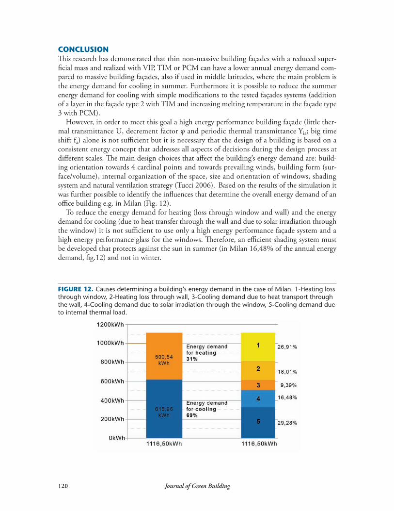
However, in order to meet this goal a high energy performance building façade (little ther-mal transmittance U, decrement factor φ and periodic thermal transmittance Yia; big time shift fa) alone is not sufficient but it is necessary that the design of a building is based on a consistent energy concept that addresses all aspects of decisions during the design process at different scales. The main design choices that affect the building’s energy demand are: build-ing orientation towards 4 cardinal points and towards prevailing winds, building form (sur-face/volume), internal organization of the space, size and orientation of windows, shading system and natural ventilation strategy (Tucci 2006). Based on the results of the simulation it was further possible to identify the influences that determine the overall energy demand of an office building e.g. in Milan (Fig. 12).
To reduce the energy demand for heating (loss through window and wall) and the energy demand for cooling (due to heat transfer through the wall and due to solar irradiation through the window) it is not sufficient to use only a high energy performance façade system and a high energy performance glass for the windows. Therefore, an efficient shading system must be developed that protects against the sun in summer (in Milan 16,48% of the annual energy demand, fig.12) and not in winter.
FIGURE 12. Causes determining a building’s energy demand in the case of Milan. 1-Heating loss through window, 2-Heating loss through wall, 3-Cooling demand due to heat transport through the wall, 4-Cooling demand due to solar irradiation through the window, 5-Cooling demand due to internal thermal load.
Volume6,Number2 121
However, to reduce the cooling demand due to internal thermal loads (in Milan 29,28% of the annual energy demand, fig.12) it is necessary to develop an appropriate strategy for natural ventilation, that uses prevailing winds and natural air movements caused by pressure differences between inside and outside.
This research has demonstrated that thin non-massive building façades realized with VIP, TIM or PCM have a high potential in reducing the annual energy demand in an office build-ing located in different Italian climatic zones. But the use of such systems must at the same time necessarily be supported by appropriate design choices. These appropriate design choices can’t be defined by scientific research, since the design of each building is a particular case. For this reason, the designer can successfully implement these tested façade systems, but has also to consider in each case the specific micro-climatic condition of the location and habits of the users (Hegger 2008).
REFERENCESCremers, J. (2007). Einsatzmöglichkeiten von Vakuum-Dämmsystemen im Bereich der Gebäudehülle—Technologische,
bauphysikalische und architektonische Aspekte. München/New York: Martin Meidenbauer.European Committee for Standardization (2008). UNI-EN-ISO-13786:2008 Thermal performance of building
components—Dynamic thermal characteristics—Calculation metods. Brussels:CEN.Hegger, M. (2008). Energy Manual. München: Detail.Herzog, T. (2004). Façade Construction Manual. München: Detail.Imperadori, M. (2006). La progettazione con tecnologia stratificata a secco. Milano: Il Sole 24 ore.Kerschberger, A. (1996). Solares Bauen mit transparenter Wärmedämmung – Systeme – Wirtschaftlichkeit – Perspektiven.
Wiesbaden: Bauverlag.Ministero dello Sviluppo Economico (2009). D.M. 26/6/2009 Linee guida nazionali per la certificazione ener-
getica degli edifici. Roma: Gazzetta ufficiale.Pfundstein, M. (2007). Insulating Materials. München: Detail. Tucci, F. (2006). Involucro ben temperato. Efficienza energetica ed ecologica in architettura attraverso la pelle degli
edifici. Firenze: Alinea.Dlgs. 311/2006 Disposizioni correttive ed integrative al decreto legislativo 19 agosto 2005, n.192, recante attuazione
della direttiva 2002/91/CE, relativa al rendimento energetico nell’edilizia. (2007). Roma: Gazzetta ufficiale. DPR 59/2009 Regolamento di attuazione dell´articolo 4 comma 1 lettere a) e b), del decreto legislativo 19 agosto
2005, n.192, concernente attuazione della direttiva 2002/91/CE sul rendimento energetico in edilizia.(2009). Roma: Gazzetta ufficiale.