Embed Size (px)
Citation preview
Geosynthetics 2015 February 15-18, Portland, Oregon
Innovative Approach to Landfill Gas Collection and Control E. S. Steinhauser, Sanborn, Head & Associates, Inc., USA, [email protected] S. Fourmont, AFITEX-TEXEL, Inc., Canada, [email protected] ABSTRACT Landfill gas (LFG) needs to be effectively extracted from active and closed landfills to comply with air quality regulations as well as to fuel beneficial uses. LFG extraction is performed by applying a vacuum to vertical wells and collection trenches or other landfill related infrastructure. LFG collection trenches are semi-permanent features used to control LFG emissions prior to installing wells. LFG collection trenches are constructed by excavating a trench into the waste mass and installing a perforated pipe bedded in and backfilled with aggregate. Each year miles of trenches are constructed in landfills requiring the excavation and relocation of significant volumes of waste. While LFG collection trenches are an important component to a well-operated landfill, there is significant cost associated with constructing trenches and relocating waste. This paper examines the use of a tubular drainage geocomposite as a LFG collection and conveyance medium. 1. INTRODUCTION Landfill gas (LFG) is produced during the decomposition of putrescible material in landfills. Often referred to as biogas, LFG is a source of odors and greenhouse gases. LFG is typically 40 to 60 percent methane with the remainder consisting of carbon dioxide with lesser concentrations of atmospheric gases (e.g., oxygen and nitrogen) and trace concentrations of other constituents (e.g., hydrogen sulfide, siloxanes). Methane is a greenhouse gas that has 25 times more of an impact on climate change than carbon dioxide (USEPA, 2013). LFG must be removed from the landfill to reduce or eliminate odors, and to limit the migration of methane to the atmosphere or nearby structures, which could result in an explosive hazard. Federal and state regulations address the collection and control of LFG, and landfill owners and operators may be required to apply for air quality permits. As such, the management of LFG at landfills is an important, and often costly, operational aspect of a well-run landfill. The need to install a gas collection and control system (GCCS) is dependent on the amount and type of waste accepted. Once installed, a properly designed and constructed GCCS can be an integral part of an environmentally sound waste material management operation. Typically, LFG is controlled by an active or passive gas system. A passive system consists of vents that emit LFG into the atmosphere; whereas an active system extracts LFG by applying a vacuum to a network of collection wells and trenches. In an active system, LFG is collected and sent to a destruction device, such as a flare, where it is combusted and the methane is converted to carbon dioxide. Because of the energy potential of the methane gas, landfill gas-to-energy (LFGTE) projects have been developed to capitalize on the “man-made” “green” fuel source. In general, LFGTE projects use the LFG to fuel specially designed turbines, reciprocating engines, or boilers. LFGTE projects can have design lives in excess of 20 years and range in size from a few kilowatts to 10 or more megawatts. Also, LFG can be processed into a compressed gas for vehicle use. The success of a LFGTE project is directly related to the performance of the GCCS. Traditional methods of LFG collection can be time consuming and expensive to install, and installation sometimes can be delayed due to seasonal and budget issues. This paper presents a geosynthetic solution that landfill owners and operators can cost effectively employ in their GCCS to enhance the success of their LFGTE projects as well as maintain compliance with regulatory requirements. 2. CURRENT LANDFILL GAS CONTROL PRACTICES There are several approaches to collecting LFG, including: (i) a gas collection layer within the final cover system; (ii) collection trenches within the waste mass; and (iii) vertical extraction wells. Some states require that the landfill final cover system include a granular gas venting layer below the cap geomembrane. While the required thickness of this section may vary from state to state (152 to 305 millimeters [mm]), this layer can be an expensive component of the final cover system, and may be difficult to construct.
283
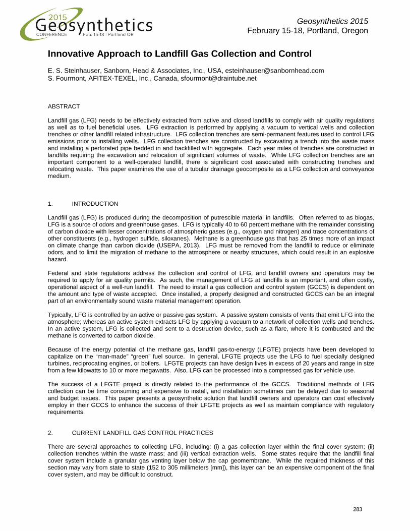
To reduce nuisance odors, gas collection trenches are often installed at some landfills to intercept fugitive emissions from the surface of the landfill. Construction of a typical LFG collection trench involves waste excavation and relocation, and the purchase and installation of perforated high-density polyethylene (HDPE) pipe and drainage aggregate. The perforated pipe is typically connected to solid HDPE pipe and a wellhead, through which vacuum, and hence the gas collection rate, can be monitored and controlled. It is common to space the LFG collection trenches about 15 to 30 meters (m) apart horizontally and about 9 to 12 m vertically (see Figure 1). Closer spacing is sometimes used when more aggressive odor reduction measures are needed. Each collection trench has a zone of influence, in which the vacuum that is applied to the trench influences the movement of LFG within the landfill. Maintaining this spacing is important for efficient LFG collection.
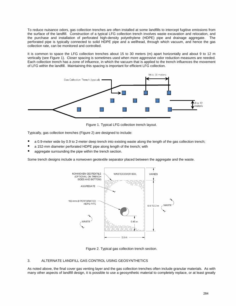
Figure 1. Typical LFG collection trench layout. Typically, gas collection trenches (Figure 2) are designed to include: a 0.9-meter wide by 0.9 to 2-meter deep trench into existing waste along the length of the gas collection trench; a 152-mm diameter perforated HDPE pipe along length of the trench; with aggregate surrounding the pipe within the trench section. Some trench designs include a nonwoven geotextile separator placed between the aggregate and the waste.
Figure 2. Typical gas collection trench section. 3. ALTERNATE LANDFILL GAS CONTROL USING GEOSYNTHETICS As noted above, the final cover gas venting layer and the gas collection trenches often include granular materials. As with many other aspects of landfill design, it is possible to use a geosynthetic material to completely replace, or at least greatly
284
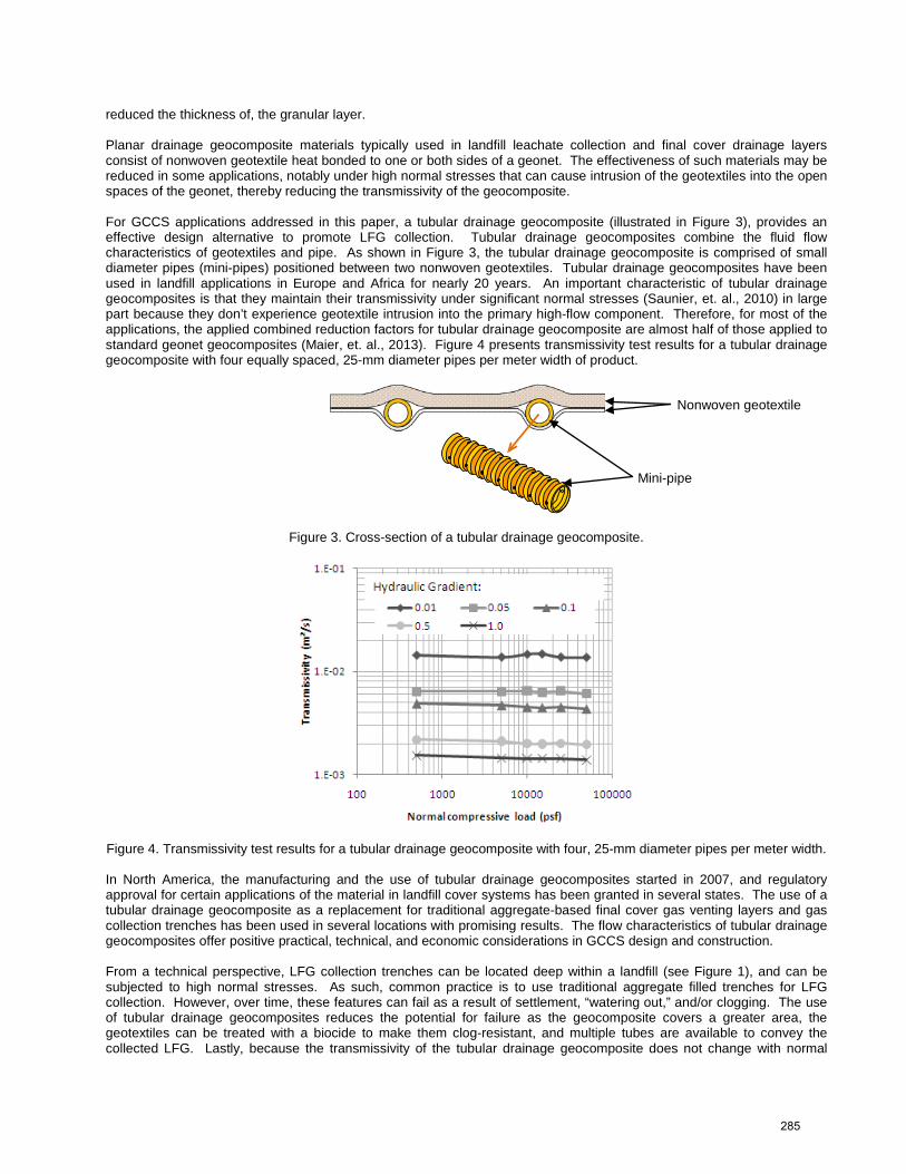
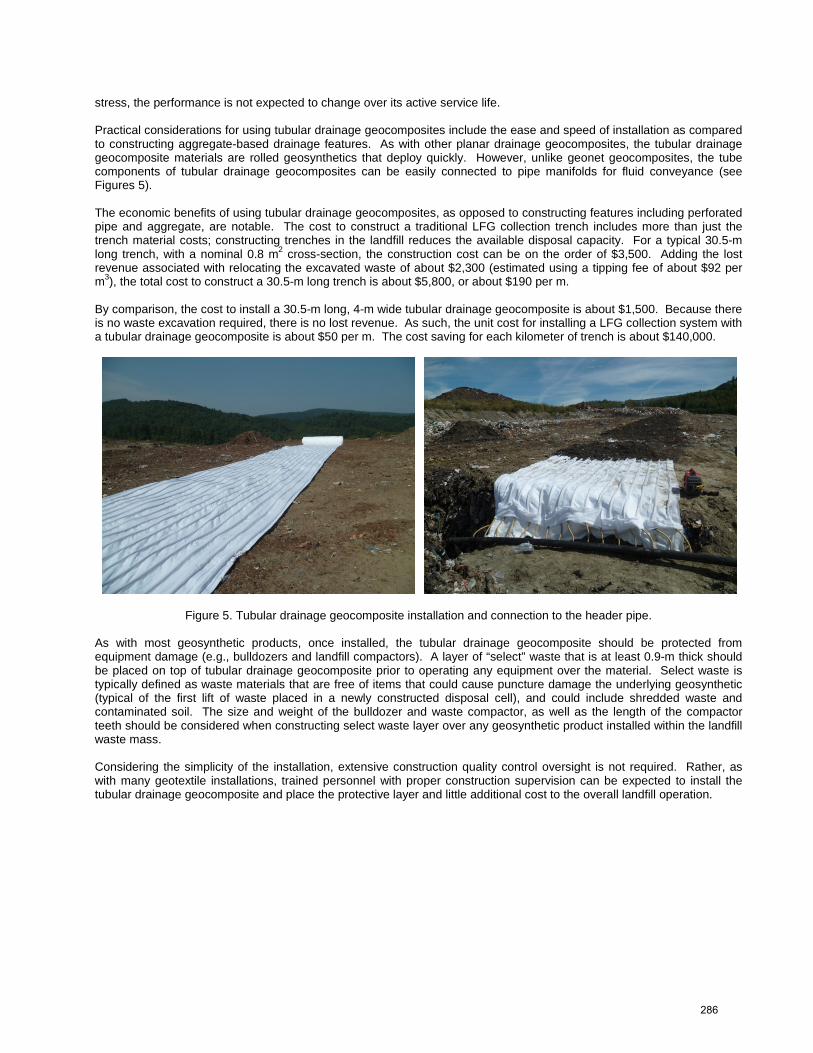
reduced the thickness of, the granular layer. Planar drainage geocomposite materials typically used in landfill leachate collection and final cover drainage layers consist of nonwoven geotextile heat bonded to one or both sides of a geonet. The effectiveness of such materials may be reduced in some applications, notably under high normal stresses that can cause intrusion of the geotextiles into the open spaces of the geonet, thereby reducing the transmissivity of the geocomposite. For GCCS applications addressed in this paper, a tubular drainage geocomposite (illustrated in Figure 3), provides an effective design alternative to promote LFG collection. Tubular drainage geocomposites combine the fluid flow characteristics of geotextiles and pipe. As shown in Figure 3, the tubular drainage geocomposite is comprised of small diameter pipes (mini-pipes) positioned between two nonwoven geotextiles. Tubular drainage geocomposites have been used in landfill applications in Europe and Africa for nearly 20 years. An important characteristic of tubular drainage geocomposites is that they maintain their transmissivity under significant normal stresses (Saunier, et. al., 2010) in large part because they don’t experience geotextile intrusion into the primary high-flow component. Therefore, for most of the applications, the applied combined reduction factors for tubular drainage geocomposite are almost half of those applied to standard geonet geocomposites (Maier, et. al., 2013). Figure 4 presents transmissivity test results for a tubular drainage geocomposite with four equally spaced, 25-mm diameter pipes per meter width of product.
Figure 3. Cross-section of a tubular drainage geocomposite.
Figure 4. Transmissivity test results for a tubular drainage geocomposite with four, 25-mm diameter pipes per meter width. In North America, the manufacturing and the use of tubular drainage geocomposites started in 2007, and regulatory approval for certain applications of the material in landfill cover systems has been granted in several states. The use of a tubular drainage geocomposite as a replacement for traditional aggregate-based final cover gas venting layers and gas collection trenches has been used in several locations with promising results. The flow characteristics of tubular drainage geocomposites offer positive practical, technical, and economic considerations in GCCS design and construction. From a technical perspective, LFG collection trenches can be located deep within a landfill (see Figure 1), and can be subjected to high normal stresses. As such, common practice is to use traditional aggregate filled trenches for LFG collection. However, over time, these features can fail as a result of settlement, “watering out,” and/or clogging. The use of tubular drainage geocomposites reduces the potential for failure as the geocomposite covers a greater area, the geotextiles can be treated with a biocide to make them clog-resistant, and multiple tubes are available to convey the collected LFG. Lastly, because the transmissivity of the tubular drainage geocomposite does not change with normal
Nonwoven geotextile
Mini-pipe
285
stress, the performance is not expected to change over its active service life. Practical considerations for using tubular drainage geocomposites include the ease and speed of installation as compared to constructing aggregate-based drainage features. As with other planar drainage geocomposites, the tubular drainage geocomposite materials are rolled geosynthetics that deploy quickly. However, unlike geonet geocomposites, the tube components of tubular drainage geocomposites can be easily connected to pipe manifolds for fluid conveyance (see Figures 5). The economic benefits of using tubular drainage geocomposites, as opposed to constructing features including perforated pipe and aggregate, are notable. The cost to construct a traditional LFG collection trench includes more than just the trench material costs; constructing trenches in the landfill reduces the available disposal capacity. For a typical 30.5-m long trench, with a nominal 0.8 m2 cross-section, the construction cost can be on the order of $3,500. Adding the lost revenue associated with relocating the excavated waste of about $2,300 (estimated using a tipping fee of about $92 per m3), the total cost to construct a 30.5-m long trench is about $5,800, or about $190 per m. By comparison, the cost to install a 30.5-m long, 4-m wide tubular drainage geocomposite is about $1,500. Because there is no waste excavation required, there is no lost revenue. As such, the unit cost for installing a LFG collection system with a tubular drainage geocomposite is about $50 per m. The cost saving for each kilometer of trench is about $140,000.
Figure 5. Tubular drainage geocomposite installation and connection to the header pipe. As with most geosynthetic products, once installed, the tubular drainage geocomposite should be protected from equipment damage (e.g., bulldozers and landfill compactors). A layer of “select” waste that is at least 0.9-m thick should be placed on top of tubular drainage geocomposite prior to operating any equipment over the material. Select waste is typically defined as waste materials that are free of items that could cause puncture damage the underlying geosynthetic (typical of the first lift of waste placed in a newly constructed disposal cell), and could include shredded waste and contaminated soil. The size and weight of the bulldozer and waste compactor, as well as the length of the compactor teeth should be considered when constructing select waste layer over any geosynthetic product installed within the landfill waste mass. Considering the simplicity of the installation, extensive construction quality control oversight is not required. Rather, as with many geotextile installations, trained personnel with proper construction supervision can be expected to install the tubular drainage geocomposite and place the protective layer and little additional cost to the overall landfill operation.
286
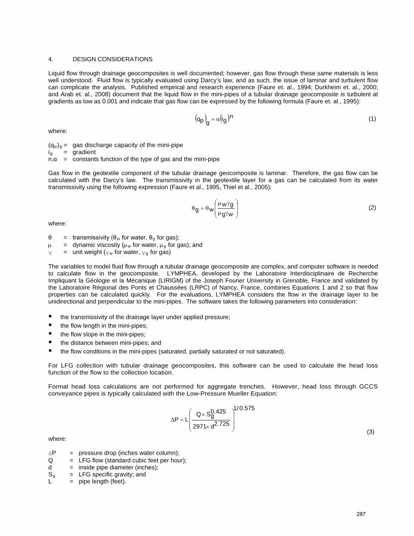
4. DESIGN CONSIDERATIONS Liquid flow through drainage geocomposites is well documented; however, gas flow through these same materials is less well understood. Fluid flow is typically evaluated using Darcy’s law, and as such, the issue of laminar and turbulent flow can complicate the analysis. Published empirical and research experience (Faure et. al., 1994; Durkheim et. al., 2000; and Arab et. al., 2008) document that the liquid flow in the mini-pipes of a tubular drainage geocomposite is turbulent at gradients as low as 0.001 and indicate that gas flow can be expressed by the following formula (Faure et. al., 1995): ( ) ( )ngigpq α= (1)
where: (qp)g = gas discharge capacity of the mini-pipe ig = gradient n,α = constants function of the type of gas and the mini-pipe Gas flow in the geotextile component of the tubular drainage geocomposite is laminar. Therefore, the gas flow can be calculated with the Darcy’s law. The transmissivity in the geotextile layer for a gas can be calculated from its water transmissivity using the following expression (Faure et al., 1995, Thiel et al., 2005):
γµ
γµθ=θ
wggw
wg (2)
where: θ = transmissivity (θw for water, θg for gas); µ = dynamic viscosity (µw for water, µg for gas); and γ = unit weight (γw for water, γg for gas) The variables to model fluid flow through a tubular drainage geocomposite are complex, and computer software is needed to calculate flow in the geocomposite. LYMPHEA, developed by the Laboratoire Interdisciplinaire de Recherche Impliquant la Géologie et la Mécanique (LIRIGM) of the Joseph Fourier University in Grenoble, France and validated by the Laboratoire Régional des Ponts et Chaussées (LRPC) of Nancy, France, combines Equations 1 and 2 so that flow properties can be calculated quickly. For the evaluations, LYMPHEA considers the flow in the drainage layer to be unidirectional and perpendicular to the mini-pipes. The software takes the following parameters into consideration: the transmissivity of the drainage layer under applied pressure; the flow length in the mini-pipes; the flow slope in the mini-pipes; the distance between mini-pipes; and the flow conditions in the mini-pipes (saturated, partially saturated or not saturated). For LFG collection with tubular drainage geocomposites, this software can be used to calculate the head loss function of the flow to the collection location. Formal head loss calculations are not performed for aggregate trenches. However, head loss through GCCS conveyance pipes is typically calculated with the Low-Pressure Mueller Equation:
575.0/1
725.2d2971
425.0gSQ
LP
×
×=∆
(3) where: ΔP = pressure drop (inches water column); Q = LFG flow (standard cubic feet per hour); d = inside pipe diameter (inches); Sg = LFG specific gravity; and L = pipe length (feet).
287
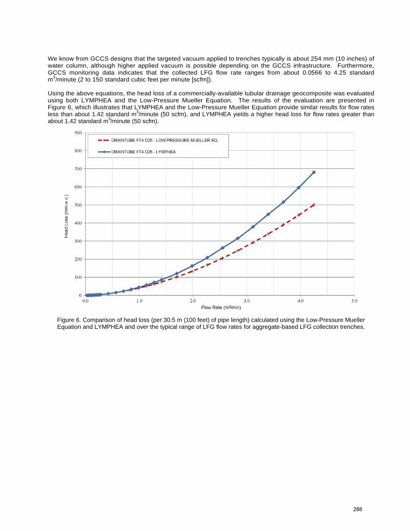
We know from GCCS designs that the targeted vacuum applied to trenches typically is about 254 mm (10 inches) of water column, although higher applied vacuum is possible depending on the GCCS infrastructure. Furthermore, GCCS monitoring data indicates that the collected LFG flow rate ranges from about 0.0566 to 4.25 standard m3/minute (2 to 150 standard cubic feet per minute [scfm]). Using the above equations, the head loss of a commercially-available tubular drainage geocomposite was evaluated using both LYMPHEA and the Low-Pressure Mueller Equation. The results of the evaluation are presented in Figure 6, which illustrates that LYMPHEA and the Low-Pressure Mueller Equation provide similar results for flow rates less than about 1.42 standard m3/minute (50 scfm), and LYMPHEA yields a higher head loss for flow rates greater than about 1.42 standard m3/minute (50 scfm).
Figure 6. Comparison of head loss (per 30.5 m (100 feet) of pipe length) calculated using the Low-Pressure Mueller Equation and LYMPHEA and over the typical range of LFG flow rates for aggregate-based LFG collection trenches.
288
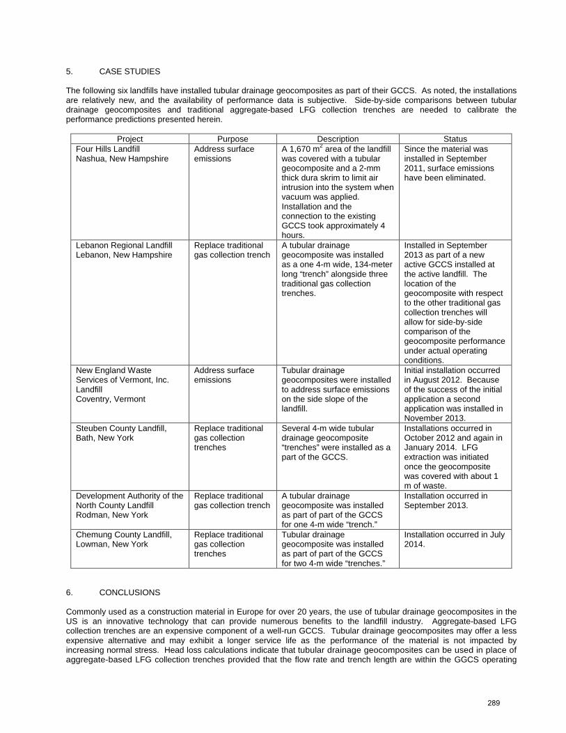
5. CASE STUDIES The following six landfills have installed tubular drainage geocomposites as part of their GCCS. As noted, the installations are relatively new, and the availability of performance data is subjective. Side-by-side comparisons between tubular drainage geocomposites and traditional aggregate-based LFG collection trenches are needed to calibrate the performance predictions presented herein.
Project Purpose Description Status Four Hills Landfill Nashua, New Hampshire
Address surface emissions
A 1,670 m2 area of the landfill was covered with a tubular geocomposite and a 2-mm thick dura skrim to limit air intrusion into the system when vacuum was applied. Installation and the connection to the existing GCCS took approximately 4 hours.
Since the material was installed in September 2011, surface emissions have been eliminated.
Lebanon Regional Landfill Lebanon, New Hampshire
Replace traditional gas collection trench
A tubular drainage geocomposite was installed as a one 4-m wide, 134-meter long “trench” alongside three traditional gas collection trenches.
Installed in September 2013 as part of a new active GCCS installed at the active landfill. The location of the geocomposite with respect to the other traditional gas collection trenches will allow for side-by-side comparison of the geocomposite performance under actual operating conditions.
New England Waste Services of Vermont, Inc. Landfill Coventry, Vermont
Address surface emissions
Tubular drainage geocomposites were installed to address surface emissions on the side slope of the landfill.
Initial installation occurred in August 2012. Because of the success of the initial application a second application was installed in November 2013.
Steuben County Landfill, Bath, New York
Replace traditional gas collection trenches
Several 4-m wide tubular drainage geocomposite “trenches” were installed as a part of the GCCS.
Installations occurred in October 2012 and again in January 2014. LFG extraction was initiated once the geocomposite was covered with about 1 m of waste.
Development Authority of the North County Landfill Rodman, New York
Replace traditional gas collection trench
A tubular drainage geocomposite was installed as part of part of the GCCS for one 4-m wide “trench.”
Installation occurred in September 2013.
Chemung County Landfill, Lowman, New York
Replace traditional gas collection trenches
Tubular drainage geocomposite was installed as part of part of the GCCS for two 4-m wide “trenches.”
Installation occurred in July 2014.
6. CONCLUSIONS Commonly used as a construction material in Europe for over 20 years, the use of tubular drainage geocomposites in the US is an innovative technology that can provide numerous benefits to the landfill industry. Aggregate-based LFG collection trenches are an expensive component of a well-run GCCS. Tubular drainage geocomposites may offer a less expensive alternative and may exhibit a longer service life as the performance of the material is not impacted by increasing normal stress. Head loss calculations indicate that tubular drainage geocomposites can be used in place of aggregate-based LFG collection trenches provided that the flow rate and trench length are within the GGCS operating
289
parameters. Empirical data from field trials where tubular drainage geocomposites are installed in place of, or side-by-side with, traditional aggregate-based LFG collection trenches is needed to better understand the material’s performance under actual GCCS operating conditions. Such evaluations should consider the different fluid flow regimes associated with planar and linear installations, as well as the overall width of the collection feature. REFERENCES Arab, R., Fourmount, S., and Gendrin, P. (2008). Lateral and Capping Landfills Drainage with Geocomposites. 1st Middle
European Conference on Landfill Technology, Budapest ; Hungary Durkheim, Y. and Gendrin, P. (2000). Drainage Design in a Landfill Lining System at the Saint Sylvestre Bas Le Roc
(Creuse france). Second European Geosynthetics Conference, Vol. 2, pp. 505 - 507. Faure, Y.H., Auvin, G. and Eloy-Giorni, C. (1994). Performance Tests and Design of Geocomposites for Drainage of Gas.
Fifth International Conference on Geotextiles, Geomembranes and Related Products, pp. 833 - 836. Faure, Y.H. and Auvin, G. (1995). Gas Drainage by Geocomposites. Recontres 95 du CFG, pp. 63 - 69. (in French) Maier, T.B. and Fourmont, S. (2013). How Tubular Drainage Geocomposite Was Used in Landfill Final Cover.
Geosynthetics, Vol. 31, No.3, pp. 48 - 51 Saunier, P., Ragen, W., and Blond, E. (2010). Assessment of the resistance of drain tube planar drainage geocomposites
to high compressive loads, 9th International Conference on Geosynthetics, Guarujá, Brazil, Vol. 3. Theil, R. and Narejo, D. (2005). Update on designing with geocomposite drainage layers in landfills – Part 2 of 4:
geocomposites on bioreactor landfill sideslopes to control seeps and gas. GFR Magazine, Vol. 23, No. 2. United States Environmental Protection Agency (2013). 40 CFR Part 98 - 2013 Revisions to the Greenhouse Gas
Reporting Rule and Final Confidentiality Determinations for New or Substantially Revised Data Elements; Final Rule, Federal Register, Vol. 78, No. 230, pp 71904 - 71980.
290