Embed Size (px)
Citation preview

Innovations ReportHenry Ayliff c1186342
AbstractDescribed here is an intuitive manipulation system for virtual scenes, using handmovements tracked by a domestic web camera. Methods for tracking position and handshape are discussed as well as methods for affecting virtual objects using this data.
IntroductionThe modelling and manipulation of computer generated 3D objects is done almostexclusively by using a keyboard and mouse as the primary inputs. While these tools haveproved adequate to achieve these tasks, they lack the intuitiveness of more natural mediasuch as clay or plastocine, where an artist can use their hands and fingers directly on themodel that is being created. If the keyboard and mouse could be eliminated then onefurther layer of abstraction between digital artists and their creations would be removed.
Existing User Input Systems SystemsSince computer graphics were first invented, there have been many innovative systemscreated to interact with these virtual worlds. The majority of these systems use some sortof specialised hardware specifically designed for the purpose, which are often expensiveand bulky.There are two main types of input devices for 3D virtual scenes, those that allow the userto manipulate in all three dimensions simultaneously, and those that manipulate only in asingle two dimensional plane at a time. An example of a three dimensional input systemwould be the Polhemus Fastrack system[1][4], which usesa small stylus whose position and orientation in real worldspace is tracked by magnetically measuring it's distancefrom a set of sensors. This data is then translated into anabsolute position and rotation inside the virtual scene. In aDataglove system the position and orientation of the handare tracked in the same way, but it goes one step furtherthan the stylus system by also measuring the orientation ofeach finger using mechanical sensors to detect the degreeof bend of each joint[1]. This allows a 3D representation of the whole hand to bereproduced in the virtual world, enabling the user to grasp and hold virtual objects in avery natural manner.
page 1
Figure1 “Polhemus Fastrack stylus andsensor” from Inition www.inition.co.uk

Other systems are also available that are entirely mechanical, theserecord the position and orientation of a handle on some sort ofactuator arm, by measuring the bend of each joint in that arm [1]. Amanipulator arm also lends itself quite conveniently to forcefeedback applications. By using motors or electromagnetic brakeson the joints of the arm, resistance to the users motions can begiven when the manipulator comes into contact with a virtual objectinside the simulation. This tactile feedback gives more of a sense ofreality to the simulation and aids the user in intuitive positioning ofthe manipulator inside the scene, they do not need to be looking atthe virtual tool to judge when it has come into contact with theobject.Three dimensional systems such as these have the advantage that the user can positiontheir tool in every degree of freedom that they would be able to in the physical world,they can move it in all three dimensions simultaneously. Because they record absolutemeasurements of the user's position, they are good for positioning objects absolutelywithin a scene, but not so good for relative motions, since the manipulator can only bemeasured within a certain area around the detector, the user is constrained within thisarea, and cannot make larger motions than this, as they could do with a mouse by liftingit up and moving it repeatedly across the same section of tabletop. The main disadvantageof these systems however, is their expense. The high price of the hardware involved, andthe fact that it can only be used for one specialised purpose, means that these systems areoutside of the reach of the majority of users.
Two dimensional input systems include conventional mice or trackballs, which drive therelative motion of a cursor on the plane of the screen, or graphics tablets, which describean absolute location on that same screen plane. Generally, the main system of output tothe user of the virtual scene is a traditional computer monitor. This means that the threedimensional objects are projected into a two dimensional image to display to the user,making it very difficult, if not impossible to judge the distance of an object away fromthe viewer. Because of this, it seems more logical to manipulate objects in twodimensions then three when they can only be sen in two dimensions.In the physical world we perceive objects in three dimensions, we can judge distance byusing our stereoscopic vision and comparing images from the left and right eye. We canalso judge shape and distance by moving the head slightly, to look at an object fromdifferent points of view. There are a variety of systems available that will displaycomputer images in three dimensions, head mounted displays or virtual reality headsets
page 2
Figure 2 “Dataglove (top)and force feedbackarmature (bottom)
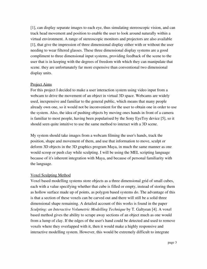
[1], can display separate images to each eye, thus simulating stereoscopic vision, and cantrack head movement and position to enable the user to look around naturally within avirtual environment. A range of stereoscopic monitors and projectors are also available[1], that give the impression of three dimensional display either with or without the userneeding to wear filtered glasses. These three dimensional display systems are a goodcompliment to three dimensional input systems, providing feedback of the scene to theuser that is in keeping with the degrees of freedom with which they can manipulate thatscene. they are unfortunately far more expensive than conventional two dimensionaldisplay units.
Project AimsFor this project I decided to make a user interaction system using video input from awebcam to drive the movement of an object in virtual 3D space. Webcams are widelyused, inexpensive and familiar to the general public, which means that many peoplealready own one, so it would not be inconvenient for the user to obtain one in order to usethe system. Also, the idea of pushing objects by moving ones hands in front of a camerais familiar to most people, having been popularised by the Sony EyeToy device [5], so itshould seen quite intuitive to use the same method to interact with a 3D scene.
My system should take images from a webcam filming the user's hands, track theposition, shape and movement of them, and use that information to move, sculpt ordeform 3D objects in the 3D graphics program Maya, in much the same manner as onewould scoop or push clay while sculpting. I will be using the MEL scripting languagebecause of it's inherent integration with Maya, and because of personal familiarity withthe language.
Voxel Sculpting MethodVoxel based modelling systems store objects as a three dimensional grid of small cubes,each with a value specifying whether that cube is filled or empty, instead of storing themas hollow surface made up of points, as polygon based systems do. The advantage of thisis that a section of these voxels can be carved out and there will still be a solid threedimensional shape remaining. A detailed account of this works is found in the paperSculpting: an Interactive Volumetric Modelling Technique by T. Galtyean [4]. A voxelbased method gives the ability to scrape away sections of an object much as one wouldfrom a lump of clay. If the edges of the user's hand could be detected and used to removevoxels where they overlapped with it, then it would make a highly responsive andinteractive modelling system. However, this would be extremely difficult to integrate
page 3

with Maya. since it's objects are polygon based not voxel based. It would be best then tofind a polygon based method to accomplish the same effect.
Boolean Sculpting Method Using the video data, the positions that the users hands have moved over could berecorded, and those portions of the image subtracted from the object. This would leave agap in the object where the hand had moved over it, in much the same manner that adepression is left when clay is scraped away from a sculpture. The data would becaptured from the images in a similar way to the drawing prism device created byRichard Greene in his paper The Drawing Prism: A Versatile Graphic Input Device [2].In Greene's system, a camera filmed theuser painting on glass with a paintbrush,fingers or other object, recording onlythe points at which it touched the glass,by means of reflection within a prism.Each successive frame was added to aframe buffer, without removing theprevious one, thus creating a trail ofcoloured pixels wherever the user hadpainted.
My system would take images from the webcam of the user's hands against a stronglycontrasting background and use the same frame buffer system to record a trail whereverthe hands had moved. The contrast could then be increased to produce a simple black andwhite image, black where the hands had been, and white where they had not. A routinewould then detect the edges of this shape, compare them to an object in the Maya sceneand use a method called boolean subtraction to remove from the object those areas wherethe hand shape overlapped with it.
page 4
Figure 3 “The Drawing Prism System” From The DrawingPrism: A Versatile Graphic Input Device: SIGGRAPH 1985.
Boolean subtractionfrom object
Compare outline to 3Dobject
Images are overlayed inframe buffer
The camera films the user’shands
Figure 4 “Stages of the boolean sculpting system”
The edge detection routine would likely be the most challenging part of this system toproduce, and I decided that this would be too difficult for me to accomplish satisfactorilyin the period of time available. So I decided to focus only on moving an object, using asomewhat different and simpler method.
Point Tracking MethodVideo data from a webcam could be captured in real time by the script, then analysed tolook for a particular point or object held by the user. If this same object is found in everyframe, it could be tracked around the screen, and it's motion used to drive the motion of acontrol object in the virtual scene.
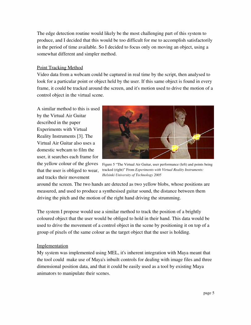
A similar method to this is usedby the Virtual Air Guitardescribed in the paperExperiments with VirtualReality Instruments [3]. TheVirtual Air Guitar also uses adomestic webcam to film theuser, it searches each frame forthe yellow colour of the glovesthat the user is obliged to wear,and tracks their movementaround the screen. The two hands are detected as two yellow blobs, whose positions aremeasured, and used to produce a synthesised guitar sound, the distance between themdriving the pitch and the motion of the right hand driving the strumming.
The system I propose would use a similar method to track the position of a brightlycoloured object that the user would be obliged to hold in their hand. This data would beused to drive the movement of a control object in the scene by positioning it on top of agroup of pixels of the same colour as the target object that the user is holding.
ImplementationMy system was implemented using MEL, it's inherent integration with Maya meant thatthe tool could make use of Maya's inbuilt controls for dealing with image files and threedimensional position data, and that it could be easily used as a tool by existing Mayaanimators to manipulate their scenes.
page 5
Figure 5 “The Virtual Air Guitar, user performance (left) and points beingtracked (right)” From Experiments with Virtual Reality Instruments:Helsinki University of Technology 2005

Obtaining images from the cameraI experienced problems when attempting to get a webcam to provide real time footage tothe MEL script, firstly because of the difficulty of obtaining drivers that would functionunder the linux system in use in the University laboratory, there being none provided bythe hardware manufacturer for linux use nor any officially endorsed by them, and alsobecause the support in the MEL language for importing binary data such as images orvideo is both limited and restricting. I decided therefore to focus on a system that wouldanalyse prerecorded images only, but which could theoretically be modified to take realtime images from a webcam. Theoretically, a camera could be set up to post images to a website at regular intervals,several times a second, overwriting the previous image each time. A MEL script couldthen download this image repeatedly each second. This would mean that the camerawould not even need to be on the same computer as the script were running on, negatingthe problem of incompatible drivers and opening the possibility of collaboration betweenCG artists on opposite sides of the world. However I did not investigate this in practicedue to the constraints of the time period available to me, and the need to focus on otheraspects of the project.
The script I created loads a sequence of images from disk into a Maya texture node, thismeans that Maya's inbuilt texture utilities can be used to manage and manipulate the file.
Analysing the imagesMaya's colorAtPoint utility is used by the script to take samples from various parts of theimage and return the RGB values from them as an array. It takes a total of 900 samplesfrom each frame in a 30 x 30 grid spread evenly across the image. The advantage ofloading the images using Maya's texture system is that the script will work with imagesof any size or proportion with no change to the code.Using only a limited set of samples, rather than checking every pixel in the image meansthat it is possible for the target object to go unnoticed if too few sample points are usedand if the target object takes up too small a part of the image. In this case, the targetobject could lie between two samples and not intersect with either one, this would mean itwould not be picked up by any sample and so would go completely undetected. As thenumber of samples taken increases however, the amount of time taken to process eachframe also increases. Since MEL is a scripting language, and not optimised for speed ofexecution, this is a serious concern, A more powerful programming language, such as C,would execute much faster than MEL, and so would in all probability be able to checkevery pixel in the image. In the course of my testing and experimentation I found that 30
page 6

x 30 samples taken in MEL provided adequate coverage to pick up any reasonable sizedtarget object, and to still execute at a reasonable speed.
Each of the samples taken from the image is checked in turn by the script, and the RGBvalues of that sample compared to the RGB values of the target colour, that is, the colourof the object that the user is holding and that is intended to be tracked. As soon as amatching sample is found, within a specified degree of tolerance, the position of thatsample within the image is found. A control object, in the form of a small sphere, ismoved to coordinates in the virtual scene that equate to that position on the image. Thecontrol object moves along a plane parallel to the XZ axis of the scene, within the boundsof a square that is 30 scene units long and wide. For the sake of clarity, the image that isbeing analysed is projected onto this same square inside the scene, so that the user can seehow the movement of the objects relates to the picture. In the system I have created, thecontrol object is fixed on this XZ plane, but in a fully featured system, the user wouldneed to be able to rotate the plane plane of motion so as to manipulate objects alongdifferent axes.
Since the control object is moved directly to the position of the sample, and since only 30x 30 samples are taken from the image, the control object seems to move in a jerky,stepped manner rather than the smooth continuous motion that would be preferable. 30 x30 samples is not really a high enough resolution to give a useful degree of control to aserious user wanting to position objects in a scene, but the same principle could easily beexpanded, by using a greater number of samples, to give a smooth user experience.
Because the first sample found to match the target colour is chosen, and the samples arechecked in order from the top leftmost to the bottom rightmost, then the rest of the imageis ignored and the control object is always sent to the top left hand corner of the targetobject in the image. This can cause problems if there are other parts of the image with asimilar colour to the target object or even just a lot of noise, since it only takes a single
page 7
Images are loaded astextures
Colour samples taken andcompared to target colour
Cursor object movedaccording to UV coordinates
of sampleFigure 6 “Stages of the point tracking system”

pixel in the wrong place of the right colour to send the control object off course. Forexample, in one test of the system, the target object was a light blue square of paper andthe user was wearing a navy blue t shirt, which appeared to be distinctly separate colours.In most frames it tracked the target perfectly, but in a few frames it picked up a sectionfrom the shirt instead. When the tolerance for changes in colour was decreased, it did notpick up anything for those frames. To counter this problem, the colour of the target objectshould be chosen with care so as to be highly different from any other colour in the shot.This would also be improved by implementing an algorithm hat looked for clusters ofpixels of the target colour, rather than just individual samples. Placing the control objectin the centre of this cluster would give a nicer feeling to the user interaction.
Manipulating ObjectsSince the initial aim of the system is to enable the user move objects around inside ascene, the control object must be able to affect and manipulate other objects within Maya.In my system this is accomplished byusing the control object to push otherobjects in the scene. In the test setup Iwas using there is only one other object,but this could easily be modified toaffect multiple objects, simply byhaving a list of all these objects andmanipulating each one in turn for eachframe.The system checks the distance betweenthe control object and the pushableobject each frame, using pythagorus'theorum to calculate this from therespective X and Z positions of eachone. If this distance is small enough that the objects would be touching then the pushableobject is moved directly away from the control object by a distance of one scene unit.The system looks only at the distance between the two objects, and does not take intoaccount their shape in any way, hence it works satisfactorily for circular objects, but formore complicated shapes it would react after passing through edges or before touchingthe object, which would not be acceptable for a serious interaction system. A moredeveloped system would have to take into account the topology of the pushable object, tolook at each of it's polygons and check whether it would intersect with the control object.The topology of the control object would not need to be taken into account since it is
page 8
Figure 7 “Screenshot of the system in Maya. The small sphereis the control object, which is following the blue paper in theimage and is about to push the large object.”

effectively just a point, the head of a tool used to manipulate other objects and has no realshape of it's own.
Shortcomings and Achievements of the SystemThis system serves as a demonstration of some of the basic aspects camera basedinteraction with a virtual three dimensional scene. However it is not fully featured enoughto be considered a practical implementation of such a system, even as a prototype.
The system succeeds in taking images from a webcam and using them to move an objectin a virtual 3D scene. However, the images are not captured in real time, which means itis not functional as a system for the user to interact with the computer, and the plane ofmotion cannot be changed, which means the object can only be positioned along the X Zplane of the virtual scene, and not along the Y axis at all.
The speed of execution of the system is rather slow, meaning that the frame rate is lowand the sample resolution is small, this means that the object moves in a jerky fashion,and since it follows only the first single sample, it tends to chase the top left corner of thetarget rather than it's centre and is prone to inaccuracies.
Tracking a single point in two dimensions, as this system effectively does at present, isnot very inspiring, and is probably better achieved using a mouse. Though this systemtracks the movement of the users hand, it does not take any account of its shape, or theposition of the fingers, which could have added a very intuitive dynamic to the process ofinteraction.This system has shown however that a system achieving all the aims set out for thisproject would be possible to produce, all the problems listed here could be addressed andsolved.
Possible Expansion of the SystemThe largest and most important factor that I would like to add would be to have imagescaptured in real time from a camera. This would achieve the primary aim of producing auser input system rather than just a system that tracks moving images. In practice, thiswould probably necessitate rewriting the system using C in order to speed up executionso that it could deal with a high enough frame rate that the lag to user response would beminimised. Faster execution would also mean that a larger number of samples could betaken, possibly up to one per pixel, which would increase the smoothness of movementacross the screen.
page 9

I would also like to use an edge detection algorithm to judge the outline of the wholeuser's hand, rather than a single point on an object they are holding. The edge of the handor fingers could then be used to push, scoop or even grasp objects on screen, adding awhole new dimension to the process of user input and becoming much more natural andintuitive than dragging things around using a single point.Finally, I would like to implement other methods of manipulation than simply pushingobjects. Adding the ability to recognise hand gestures, to push and pull vertices bypinching them between fingers or to paint textures by using a fingertip as a brush. It would also have been nice to create a graphical user interface to do things such asspecify the path of the image sequence and change the number of samples taken fromeach frame.
In hindsight, I think that because I am so used to using a mouse to interact with virtualscenes, the product I actually produced seems to have become gradually more like amouse over the course of the project. Whenever I faced a challenge, it was the optionmost similar to a mouse's functionality that seemed to me the most logical and simplest,perhaps only because it was the most familiar to me.If I were to start this project over, I would try to focus more on recognising the shape ofthe hand and using that shape to affect objects in the scene, since that seems to me now afar more innovative application than tracking the position of a hand, and it is closer towhat my original aim was.
ConclusionThe project succeeded in demonstrating some, but not all of the principles needed toaccomplish its aim. It did not take images from a camera in real time, but did analyseimages recorded previously. It did not track the shape of the fingers to scoop or mouldobjects, but it did track the position of the hand, to move objects. It provided limitedinput from a user by means of gestures recorded by a webcam, but not in real time.
References
[1] Inition Ltd. Inition Products [online]. 79 Leanord Street, London.available from http://www.inition.co.uk/inition/products.php[accessed 9th March 2006]
[2] Greene R. 1985. The Drawing Prism: A Versatile Graphic Input Device. SIGGRAPH proceedings volume 19. 103110.
page 10

[3] MäkiPatola T. Kanerva J.L.A. Takala. T. 2005. Experiments with Virtual RealityInstruments. Labarotory of Telecommunications Software and Multimedia, Helsinki University of Technology.
[4] Galtyean T.A. Hughes J.F. 1991. Sculpting: An Interactive Volumetric ModellingTechnique . Computer Graphics volume 25. 267274
[5] Sony. 2006. EyeToy.com [online].available from http://www.eyetoy.com. [accessed 9th March 2006]
Appendix – MEL script code
page 11
/****************************** tracking movement from images ********************************************/
proc checkImage ( float $array[], int $sampleU, int $sampleV){ /*acceps an array of rgb values and finds those points that are within the target colour range*/
/*if there is more than one pixel mathcing, it gets the top left one*/
int $i;for( $i=0; $i <= ($sampleU * $sampleV *3); $i+=3 ) /*for each pixel sampled*/{
if ( matchesColour($array, $i) ) /*if the pixel matches the target colour*/{
/*find the x y position that corresponds to that pixel*/findUV($i, $sampleU);print ("at index " + $i + " R: " + $array[$i] + "\n");print (" " + $i + " G: " + $array[$i+1] + "\n");print (" " + $i + " B: " + $array[$i+2] + "\n");
/*move the object to that position*/moveTo( findUV($i, $sampleU) );return;
}}
}
proc int matchesColour( float $array[], int $i ){ /*takes an array of rgb values, and an index of that array, checks if the values at that*/
/*index are close enough to the target values defined within this procedure*/
float $R = 0.17;float $G = 0.36;float $B = 0.88;float $tolerance = 0.3;
if ( $array[$i] > ($R $tolerance) )if ( $array[$i] < ($R + $tolerance) ) /*is it close to target R value?*/
if ( $array[$i+1] > ($G $tolerance) )if ( $array[$i+1] < ($G + $tolerance) ) /*is it close to target G value*/
if ( $array[$i+2] > ($B $tolerance) )if ( $array[$i+2] < ($B + $tolerance) ) /*is it close to target B value?*/
{ /*if so then...*/print "colours match\n";return 1;
} /*or else...*/return 0;
}

page 12
proc vector findUV( int $index, int $sampleU){ /*takes the index of an array and calculates the row and column of that value from the number*/
/*of items in a row*/
int $row;int $col;
/*find the row*/$row = ( trunc( $index / ($sampleU *3) ) );
/*find the column*/$col = ( ( $index ($sampleU * 3 * $row) ) /3 );
/*return the values*/vector $position = << $row, 0, $col>>;
return $position;}
proc moveTo ( vector $position ){ /*takes an xyz vector and moves the control object to that position*/
move ($position.x) ($position.y) ($position.z) ControlObject;}
proc ImageSequence(string $filename, int $startNum, int $endNum){ /*loads each image of an image sequence in turn*/
int $i;for($i=$startNum; $i <= $endNum; $i++ ){
ChangeImage($filename, $i);CheckOverlap( "MovingObject", "ControlObject" );refresh cv;
}}
proc ChangeImage(string $filename, int $frameNum){ /*loads the next image of an image sequence, and calls the checking procedure*/
setAttr type "string" file1.fileTextureName ( $filename + $frameNum +".tif"); checkImage(`colorAtPoint o RGB su 30 sv 30 file1`, 30, 30);
}
/*********************************** moving other images with the cursor ************************************/
proc float distance(string $object1, string $object2){ /*returns distance between two objects*/
/*find x distance*/float $xDist= ( getAttr($object1+".tx") getAttr($object2+".tx") );
/*find y distance*/float $zDist= ( getAttr($object1+".tz") getAttr($object2+".tz") );
/*calculate hypotenuse*/float $value=( sqrt (pow($xDist, 2) + pow($zDist, 2)) );return $value;
};
proc CheckOverlap(string $mover, string $obstacle){ /*checks if they are overlapping and moves if neccesary*/
float $touchingDistance = (`getAttr MovingObject.sx` + 1);
if( distance($mover, $obstacle) < $touchingDistance)MoveAwayFrom($mover, $obstacle);
}
proc MoveAwayFrom(string $mover, string $obstacle){ /*finds the angle vector btween the objects and moves*/
/*it away by a small amount along that vector*/

page 13
float $vectorX = getAttr($mover+".tx") getAttr($obstacle+".tx");float $vectorZ = getAttr($mover+".tz") getAttr($obstacle+".tz");
float $length = ( abs($vectorX) + abs($vectorZ) );
float $unitX =( $vectorX / $length );float $unitZ =( $vectorZ / $length );
move r $unitX 0 $unitZ $mover;}
/******************************* to run the script *************************************/
ImageSequence("/bacva3/hayliff/Innovations/WebcamFootage/BluePaper/BlueTest",111,115);
/***************************************************************************************/
/////////////////To Set The Scene//////////////////*make objects*/sphere n ControlObject;sphere n MovingObject;setAttr MovingObject.sx 3;setAttr MovingObject.sz 3;
nurbsPlane n PicturePlane;setAttr PicturePlane.rx 90;setAttr PicturePlane.ry 180;setAttr PicturePlane.rz 90;setAttr PicturePlane.sz 30;setAttr PicturePlane.sy 30;setAttr PicturePlane.tx 15;setAttr PicturePlane.tz 15;
/*make textures*/shadingNode asTexture file n file1;shadingNode asShader lambert n pictureShader;connectAttr f file1.outColor pictureShader.color;assignSG pictureShader PicturePlane;/////////////////