Embed Size (px)
Citation preview

I2C Logic Selection GuideAdvanced I2C Devices: Innovation in a Mature Technology
GTLP
2500
655
400
35
10
10 0 10 100 1000
1
0.1
BTLETL
GeneralPurpose Logic
1394.a
RS-232
RS-422
RS-423
LVDS=RS-644ECL/PECL/LVPECL
RS-485
I2C
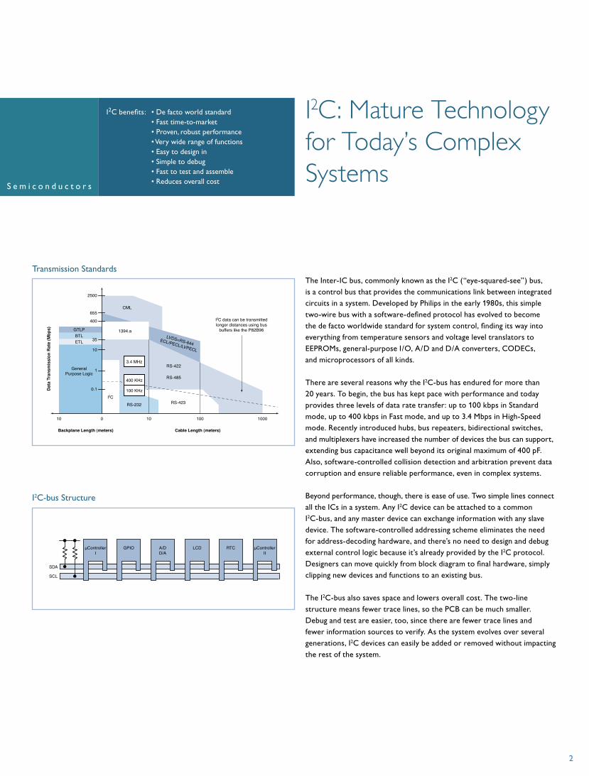
I2C data can be transmittedlonger distances using bus
buffers like the P82B96
Backplane Length (meters) Cable Length (meters)
Dat
a Tr
ansm
issi
on R
ate
(Mbp
s)
CML
3.4 MHz
100 KHz
400 KHz
Transmission Standards
SDA
µControllerI
µControllerII
GPIO A/DD/A
LCD RTC
SCL
2
I2C benefits: I2C: Mature Technology for Today’s Complex Systems
I2C-bus Structure
• De facto world standard• Fast time-to-market• Proven, robust performance• Very wide range of functions• Easy to design in• Simple to debug• Fast to test and assemble• Reduces overall cost
The Inter-IC bus, commonly known as the I2C (“eye-squared-see”) bus, is a control bus that provides the communications link between integrated circuits in a system. Developed by Philips in the early 1980s, this simple two-wire bus with a software-defined protocol has evolved to become the de facto worldwide standard for system control, finding its way into everything from temperature sensors and voltage level translators to EEPROMs, general-purpose I/O, A/D and D/A converters, CODECs, and microprocessors of all kinds.
There are several reasons why the I2C-bus has endured for more than 20 years. To begin, the bus has kept pace with performance and today provides three levels of data rate transfer: up to 100 kbps in Standard mode, up to 400 kbps in Fast mode, and up to 3.4 Mbps in High-Speed mode. Recently introduced hubs, bus repeaters, bidirectional switches, and multiplexers have increased the number of devices the bus can support, extending bus capacitance well beyond its original maximum of 400 pF. Also, software-controlled collision detection and arbitration prevent data corruption and ensure reliable performance, even in complex systems.
Beyond performance, though, there is ease of use. Two simple lines connect all the ICs in a system. Any I2C device can be attached to a common I2C-bus, and any master device can exchange information with any slave device. The software-controlled addressing scheme eliminates the need for address-decoding hardware, and there’s no need to design and debug external control logic because it’s already provided by the I2C protocol. Designers can move quickly from block diagram to final hardware, simply clipping new devices and functions to an existing bus.
The I2C-bus also saves space and lowers overall cost. The two-line structure means fewer trace lines, so the PCB can be much smaller. Debug and test are easier, too, since there are fewer trace lines and fewer information sources to verify. As the system evolves over several generations, I2C devices can easily be added or removed without impacting the rest of the system.

Old Design New DesignNeeds More Control Lines
I2C Solves the Problem
Simple LCDwith Backlight
Aux Keypad
LED Array
Aux Keypad
LED Array
Microcontroller Microcontroller
I2C LED Blinker
I2C
Microcontroller
Portable Device Applications
Innovative Products for Better Designs
Connectors
SCL
SDA
Transceivers
I2C Master or Slave Devices
PCA9510/11/12/13 or 14
Hot Swap Applications Including cPCI, VME, and Advanced TCA

GPIO
Bus Controller100 kHz Microcontroller
Microprocessor100 kHz and 400 kHz
EEPROMMultiplexer
LEDBlinker
GPIO
LED
Repeater
EEPROM
Switch
Keypad
Relay
ModeSelector
Reset
Interrupt
Disable
Reset
Inputs
Outputs
Remote
I2C I2C
SensorTempSensor
1
TempSensor
2
TempSensor
3
TempSensor
4
1.8V
2.5V
3.3V 5V
5V5V
3.3V3.3V
1.8V
2.5V
3.3V 5V
General-purpose Applications
SDRAM8~64 MBFlash
8~256 MBSD/MS/MMCI/FCard bus
I/F
USB I/F1394
I2C I/FWired I/F
I2C
Card bus &1394 IC
BluetoothIrDA
WirelessAccess
WirelessEthernetUART I/F
Wireless I/F
Memory I/F
UART
RF ModuleGPRSGSMIrDA
CommunicationInterface
Codec I/F
Touch Panel I/FLCD Display
PowerManagement
Power ControllerBacklight Control
Voltage SupervisorReset IC
Battery (Li, NiMH)
ProcessorEEPROM
EEPROM
LCD
AudioCodec Audio
AMP
MicrophoneAMP Microphone
LED
Headphone
Speaker
I/O ShortButtonKeypad ExtendKeypad
LCD TouchPanel
Touch PanelController
MCOS CameramoduleTone Generator
Camera ImageProcessor
MCU
MCU
I2C/IFDevice
(Bar codeScanner)
I2C/IFDevice
(ISP 1301BS)
LED Blinkeror
GPIO
GPIO
Bus Control
Bus ControlEEPROM
EEPROM
RTC
Display
PDA and Smartphone Applications
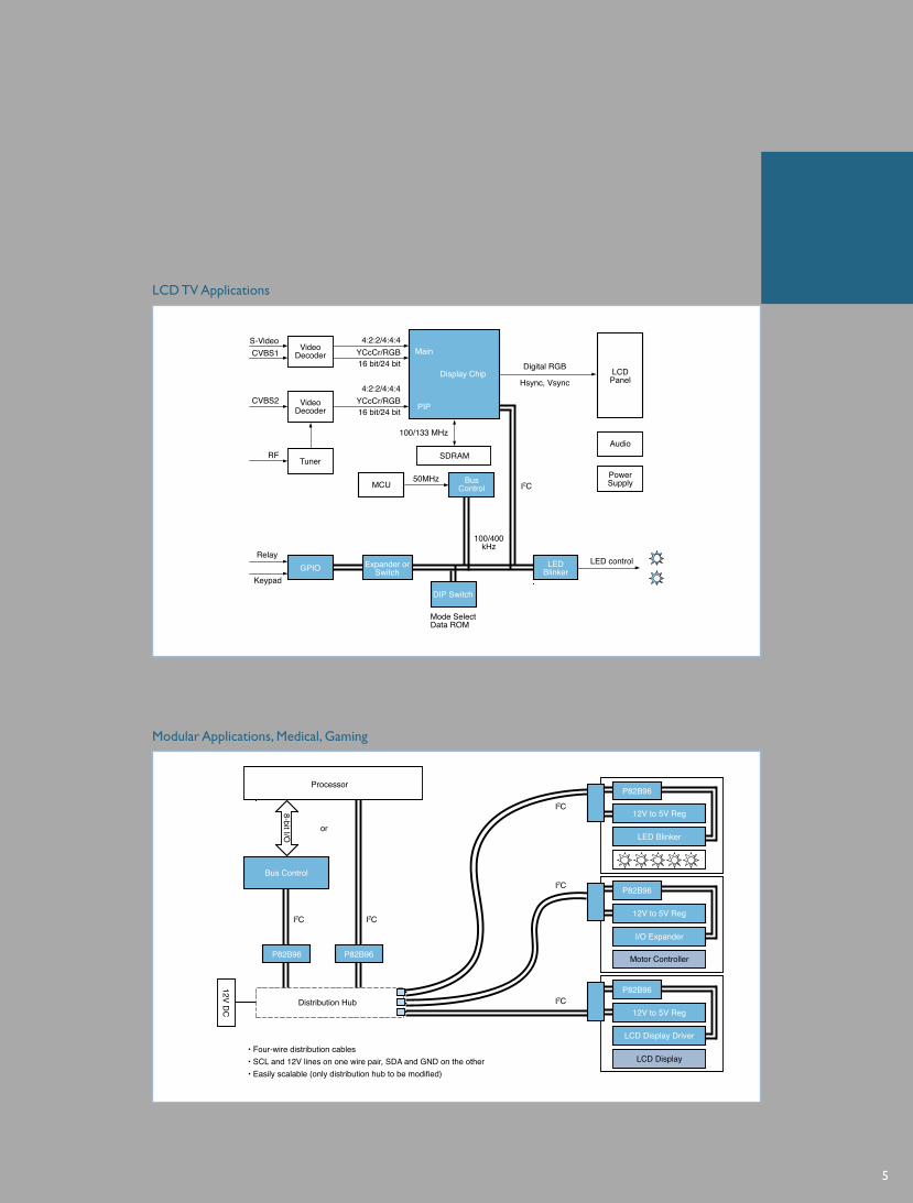
S-Video 4:2:2/4:4:4
16 bit/24 bitYCcCr/RGB
4:2:2/4:4:4
16 bit/24 bitYCcCr/RGB
CVBS1
CVBS2
RF
VideoDecoder
VideoDecoder
Tuner
Display Chip LCDPanel
Audio
PowerSupply
100/133 MHz
SDRAM
50MHzMCU
DIP Switch
Mode SelectData ROM
Relay
Keypad
Expander orSwitchGPIO
100/400kHz
LEDBlinker
LED control
BusControl
Digital RGB
Hsync, Vsync
Main
PIP
I2C
LCD TV Applications
Processor
or
Bus Control
P82B96
12V DC
P82B96
P82B96
12V to 5V Reg
12V to 5V Reg
12V to 5V Reg
Motor Controller
I/O Expander
LCD Display Driver
LCD Display
LED Blinker
P82B96
P82B96
I2C
I2C
I2C
I2CI2C
8-bit I/O
Distribution Hub
• Four-wire distribution cables• SCL and 12V lines on one wire pair, SDA and GND on the other• Easily scalable (only distribution hub to be modified)
Modular Applications, Medical, Gaming
5

I2C Product Families
PORSupply
SDA
OSC
SCL
A2
A1
A0
Internal / ExternalOscillator
DataRegisters
AnalogReference
I2C-busInterface
Sub AddressDecoder
I2C Analog-to-Digital Converter
Parallel-Bus-to-I2C-bus Controllers
Chip Enable
OperationControl
Control
SDA
SCL
Bus Buffer MicrocontrollerData
I 2C Interface
Write StrobeRead StrobeResetAddress InputsInterrupt Request
/8
I2C-bus Repeaters, Hubs, and Extenders
SDA SDA
SCL SCL
Enable
- Converts signals from digital to analog, analog to digital- Four-channel A/D converter- One-channel D/A converter- Internal oscillator- Power On Reset (POR)
- Interfaces most 8-bit parallel-bus microcontrollers and microprocessors to I2C-bus- Parallel bus system communicates bi-directionally with I2C-bus- Provides master and slave functions- I2C-bus communications carried out on byte-wise basis, using interrupt or polled handshake- Controls all I2C-bus-specific sequences (protocol, arbitration, timing) - Internal oscillator (PCA9564)- Multi-master capable
- Bi-directional I2C drivers isolate I2C-bus capacitance, accommodating more I2C devices and longer bus length
- Up to 400-pF load on each segment- Different voltages (3.3 or 5 V) on each segment- Devices transparent to bus arbitration and contention protocols in multi-master environment- Twisted pair differential transmission or opto-electrical isolation of I2C-bus (P82B96)
6
PCF8591 100-kHz 4-channel 8-bit A/D and D/A Converter
PCA9510/11/12/13/14 I2C Hot Swap Bus Buffers
PCA9515/15A I2C-bus Repeater
PCA9517 Low-voltage I2C-bus Repeater
PCA9516/16A 5-channel I2C Hub
PCA9518 Expandable 5-channel I2C Hub
P82B96 Dual Bi-directional I2C-bus Buffer
P82B715 I2C-bus Extender
PCA9564 400-kHz 2.3-to-3.6-V I2C-bus Controller
PCA8584 100-kHz 4.5-to-5.5-V I2C-bus Controller

Mux Select
SDA
SCL
Mux
EEPRO
M
Output
Default
I2C EEPROM-based DIP Switches
I2C LED Dimmers/Blinkers
Supply
Reset POR
I2C-busInterface
Latches Input/OutputStages
Sub AddressDecoder
Oscillator
SDA
SCL
A2
A1
A0
I2C General-purpose I/O (GPIO) Expanders
Supply Interrupt
Reset POR
I2C-busInterface
Latches Input/OutputStages
Sub AddressDecoder
Interrupt
SDA
SCL
A2
A1
A0
- Replace jumpers and DIP switches- Hands-free manipulation via integrated, I2C-controlled EEPROM and multiplexer- Program and store settings in I2C-controlled EEPROM register- Multiplex between default values and stored settings- Non-volatile memory retains register values, even on power-down
- Extend GPIO from I2C or SMBus - Connect parallel I/O to serial I2C or SMBus
and provide I/O expansion - Quasi output: upper transistor is on for half
a clock cycle and then held up by a weak
current source (25-mA sink)- True Output: configurable as input or output
with polarity inversion (push/pull with 25-mA sink and 10-mA source)
- General-purpose I/O and LED control- No external components required: internal
oscillator provides two (256-step, user-definable) frequency and duty cycles
- Two programmable blink rates- Single-transmission control of LED on/off/blink
- LED brightness controlled by setting frequency to 152 Hz and changing duty cycle to vary LED’s average current
- Extra pins can be used as inputs or outputs- Hardware reset pin for state machine- 25-mA, high-current open drain outputs
7
PCA8550 4-bit Multiplexed / 1-bit Latched 5-bit I2C EEPROM
PCA9559 5-bit Multiplexed / 1-bit Latched 6-bit I2C EEPROM
PCA9560 Dual 5-bit Multiplexed / 1-bit Latched I2C EEPROM
PCA9561 Quad 6-bit Multiplexed I2C EEPROM
Quasi Output (Weak Current Source)
PCA9500 8-bit with 2-kbit EEPROM
PCA9501 8-bit with 2-kbit EEPROM, Interrupt
PCA9558 8-bit w/ 5-bit DIP, 2-kbit EEPROM
PCF8574/74A 8-bit with Interrupt
PCF8575/75C 16-bit with Interrupt
True Output (Configurable Push/Pull)
PCA9536 4-bit with Interrupt
PCA9537 4-bit with Interrupt, Reset
PCA9538 8-bit with Interrupt, Reset
PCA9539 16-bit with Interrupt, Reset
PCA9534/54/54A 8-bit with Interrupt
PCA9535/55 16-bit with Interrupt
PCA9557 8-bit with Reset
LED Dimmers (Freq. Range: 152 Hz to 1.69 sec.)
PCA9530 2-bit I2C / SMBus LED Dimmer
PCA9533 4-bit I2C / SMBus LED Dimmer
PCA9531 8-bit I2C / SMBus LED Dimmer
PCA9532 16-bit I2C / SMBus LED Dimmer
LED Blinkers (Freq. Range: 44 Hz to 5.82 sec.)
PCA9550 2-bit I2C / SMBus LED Blinker
PCA9553 4-bit I2C / SMBus LED Blinker
PCA9551 8-bit I2C / SMBus LED Blinker
PCA9552 16-bit I2C / SMBus LED Blinker

SCLSDA
I2CController
I2C Bus 0
I2C Bus 1
Interrupt 0
OFF
Interrupt 1
Interrupt
Reset
I2C Multiplexers and Switches
I2C Real-time Clocks
Supply
32kHz
SDA
SCL
A0
Counters:Year, Month, Day,
Hour, Minute, Second
(240 Byte RAM 8583)
Alarm and Timer Registers
I2C-busInterface
Interrupt
Oscillator/Prescaler
POR
Sub AddressDecoder
Interrupt
I2C LCD Segment Drivers
SDA
SCLControl Logic
RAM Sequencer
Segment(Column)
Driver
Bias VoltageGenerator
Backplane(Row)Driver
Power Supplies
- Fans I2C-bus out to multiple I2C-buses - Buses selected via I2C commands from master- Multiplexers and switches select one
downstream I2C-bus at a time - Switches can, in broadcast mode, turn on all
channels simultaneously
- Interrupts are collected and sent to master- Reset pin deselects all channels, so master can
regain control if bus hangs up- Designed for address conflict resolution, I2C
sub-branch isolation, I2C-bus level shifting, etc.
- 32.768-kHz quartz oscillator- Year, month, day, hour, minute, second (1/100-sec resolution)- Alarm and timer functions- Wide operating supply voltage range (1.0 to 5.5 V)- Open drain interrupt pin - Low back-up current (0.25 µA at 3 V)- Low-voltage detection
- Low power- On-chip bias- Temperature compensation
- Blinking- No external parts required
8
PCF8563 Low-power I2C Real-time Clock
PCA8565 High-temperature (125 °C) I2C Real-time Clock
PCF8583 I2C Real-time Clock with 240-Byte RAM
PCF8593 I2C Real-time Clock with 1/100-second Resolution
PCF8562 32-to-128 I2C LCD Segment Driver
PCF8566 24-to-96 I2C LCD Segment Driver
PCF8577C 32-to-64 I2C LCD Segment Driver
PCF8576(C, D) 40-to-160 I2C LCD Segment Driver
PCF8578/79 >384 I2C LCD Segment / Dot Driver
PCF2113/2119 I2C LCD Character Display
PCF88xx I2C Color LCD Segment Drivers (consult Internet for full listing)
SAA1064 4 x 7 I2C LED Segment Driver with Decimal
PCA9540B 1-to-2 Multiplexer
PCA9541 2-to-1 Master Select w/ Int, Reset
PCA9542A 1-to-2 Multiplexer with Interrupt
PCA9543A 1-to-2 Switch w/ Interrupt, Reset
PCA9544A 1-to-4 Multiplexer w/ Interrupt
PCA9545A 1-to-4 Switch w/ Interrupt, Reset
PCA9546A 1-to-8 Switch with Reset
PCA9547 1-to-8 Multiplexer with Reset
PCA9548A 1-to-8 Switch with Reset
PCA9549 8-bit Bus Switch with Reset

AddressPointer
256-byteEEPROM
PORSupply
SDA
SCL
A2
A1
A0
I2C-busInterface
Sub AddressDecoder
I2C Serial EEPROMs
I2C Temperature and Voltage Sensors
LM75A
SupplyPOR
I2C-busInterface
Sub AddressDecoder
Interrupt
ThresholdHysteresis
ADC
INT
SDA
SCL
A2
A1
A0
I2C Voltage Level Translators
1.8 V
1.5 V
5 V
200 K
356
356
1.2 V
1.0 V
VCORE VCC
CPU I/O
GND
SREF
S1
S2Chipset I/O
GREF
DREF
D1
D2
GTL2002
- Wide voltage range minimizes EEPROM inventory
- I2C-bus reads/writes information to/from memory
- Wide voltage range (2.5 to 5.5 V)- 1,000,000 read/write cycles- 10-year data retention
- Hardware monitors use I2C-bus to report temperature and/or voltage- Remote sensor is more accurate than package-mounted sensors (analog input pins let
external transistors and diodes – in a processor, for example – perform very precise temperature sensing)
- Voltage translation between any voltage from 1.0 to 5.0 V- Open drain on both sides with no drive- Bi-directional voltage translation with no direction pin- Reference voltage clamps input voltage with low propagation delay- Supports bi-directional translation of normal 3.3- and/or 5.0-V I2C-bus signals to low-voltage
I2C processor ports- BiCMOS process for excellent ESD performance
I2C Product Families
9
NE1617A ±2 °C Local / Remote I2C Temperature Monitor
NE1618 ±1 °C High-accuracy Local / Remote I2C Temperature Monitor
NE1619 ±2 °C Local / Remote I2C Temperature and Voltage Monitor
SA56004X ±1 °C Local / Remote Digital Temp Sensor with Over-temp Alarms
LM75A ±2 °C Digital I2C Temperature Sensor and Thermal Watchdog™
SE95 ±1 °C Digital I2C Temperature Sensor and Thermal Watchdog
GTL2000 22-bit Bi-directional I2C Voltage Level Translator
GTL2002 2-bit Bi-directional I2C Voltage Level Translator
GTL2010 10-bit Bi-directional I2C Voltage Level Translator
PCA24S08 1024 x 8-bit (8-kbit) I2C Serial EEPROM with Security Features
PCF8570 256 x 8-bit (2-kbit) I2C Static Low-voltage RAM
PCF8581(C) 128 x 8-bit (1-kbit) I2C Serial EEPROM
PCF8582C-2 256 x 8-bit (2-kbit) I2C Serial EEPROM
PCF8594C-2 512 x 8-bit (4-kbit) I2C Serial EEPROM
PCF8598C-2 1024 x 8-bit (8-kbit) I2C Serial EEPROM
PCF85102C-2 256 x 8-bit (2-kbit) I2C Serial EEPROM
PCF85103C-2 256 x 8-bit (2-kbit) I2C Serial EEPROM with Alternate I2C Address
PCF85116-3 2048 x 8-bit (16-kbit) I2C Serial EEPROM
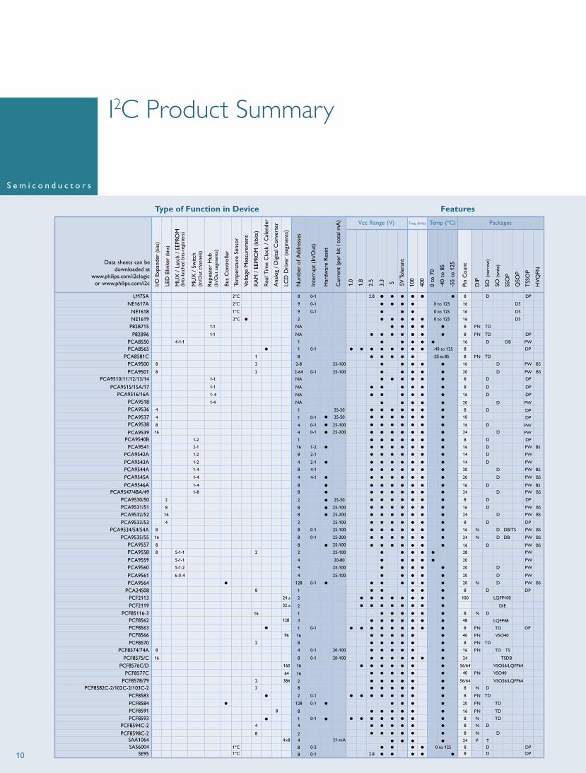
I2C Product Summary
LM75ANE1617A
NE1618NE1619
P82B715
P82B96PCA8550
PCA8581CPCA9500
PCA9501PCA9510/11/12/13/14
PCA9515/15A/17PCA9516/16A
PCA9518
PCA9541PCA9540B
PCA9539
PCA9538PCA9537
PCA9536
PCA9542A
PCA9543APCA9544APCA9545A
PCA9546APCA9547/48A/49
PCA9530/50PCA9531/51PCA9532/52
PCA9533/53PCA9534/54/54A
PCA9535/55PCA9557PCA9558
PCA9559PCA9560
PCA9561PCA9564
PCA24S08PCF2113
PCF85116-3PCF2119
PCF8563PCF8562
PCA8565
PCF8566PCF8570
PCF8574/74A
PCF8575/CPCF8576C/D
PCF8577CPCF8578/79
PCF8582C-2/102C-2/103C-2PCF8583PCF8584PCF8591PCF8593
PCF8594C-2
PCF8598C-2SAA1064SA56004
SE95
I/O E
xpan
der
(bits
)
LED
Blin
ker
(bits
)
MU
X /
Lat
ch /
EEP
ROM
(bits
-latc
hed
bits
-reg
iste
rs)
MU
X /
Sw
itch
(In/
Out
cha
nnel
s)
Rep
eate
r H
ub(I
n/O
ut s
egm
ents
)
Bus
Con
trol
ler
Tem
pera
ture
Sen
sor
Volta
ge M
easu
rem
ent
RA
M /
EEP
ROM
(kb
its)
Rea
l Tim
e C
lock
/ C
alen
der
Ana
log
/ D
igita
l Con
vert
er
LCD
Dri
ver
(seg
men
ts)
Num
ber
of A
ddre
sses
Inte
rrup
t (I
n/O
ut)
Har
dwar
e R
eset
Cur
rent
(pe
r bi
t / t
otal
mA
)
1.0
1.8
2.5
3.3 5 5V
Tol
eran
t
100
400
0 to
70
-40
to 8
5
-55
to 1
25
Pin
Cou
nt
DIP
SO (
narr
ow)
SO(w
ide)
SSO
P
QSO
P
TSS
OP
HV
QFN
Vcc Range (V) PackagesTemp (ºC)Freq (kHz)
8
8
16
8
8
8
16
2
8
16
4
8 1 8 D DP
4x8
4-1-1
5-1-1
5-1-1
5-1-2
6-0-4
2-1
1-2
1-2
1-4
1-4
1-4
1-8
1-
1-1
1-1
1
1-1
1- 4
1-4
2ºC
2ºC
1ºC
1ºC 0 to 1251ºC
88
DD
DPDP
2ºC
1
2
2
2
16
2
2
2
4
8
8
8
0-2
0-1
8
24
128 3
ch
32ch
96
160
64
384
8
9
9
2
NA
NA
1
8
2-8
2-64
NA
NA
NA
NA
16 1-2
8
4
8
4
8
8
2
8
8
2
8
8
8
2
4
4
4
128
2
2
1
1
1
16
8
4
8
16
16
2
8
2
128
8
1
4
24
0-1
0-1
0-1
0-1
2-1
2-1
4-1
4-1
0-1
0-1
0-1
0-1
0-1
0-1
0-1
0-1
0-1
0-1
25-100
25-50
25-50
25-100
25-200
8
10
16
24
DP
DP
PW
PW
D
D
D
25-100
25-50
25-100
25-200
25-100
25-100
25-200
25-100
25-100
20-80
25-100
25-100
20-100
20-100
21-mA
DPD8
DS 0 to 125
2.8
2.8
0 to 125
0 to 125
DS16
16
16
DS
TD
TD
TD
NP8
NP8
WPDBD16
NP858 ot 52-
-40 to 125
DPD8
DPD16
D16
D
PW
PWD14
PWD14
SB
BS
BS
PWD20
SBPWD20
PWD16
PWD24
DPD8
PWD16
PWD24
SB
SB
BS
8 DPD
PWD24
PWD16
PW28
PW20
PWD20
PWD20
PWD20
SB
SB
LQFP100
DIE
LQFP48
100
DN
N
N
N
8
48
8 TDNP DP
8 DP
40 NP VSO40
TDNP8
TDNP16 TS
24 TSDB
VSO56/LQFP64
40 NP SO40V
VSO56/LQFP6456/64
56/64
DN8
8 NP
TD
TD
NP20
TDNP16
8 TDN
DN8
T
8
24
N
P
D
SBPWD
D
16
DP
DP
D8
PW20
SBPW20
PWDB/TS
DB
D16
SB
SB
Data sheets can bedownloaded at
www.philips.com/i2clogicor www.philips.com/i2c
1-2 1 D8 DP
8
8
4
4
16
4
1
1
4
0-1
0-1
0-1
Type of Function in Device Features
10

I2C Frequently Asked Questions
Problem Description
Putting too many of the same devices on the bus causes an address conflict.
I need more devices than the 400 pF load allows.
I have to send I2C through a really long cable.
I have a mixed-voltage environment that causes conflicts on the open-drain I²C-bus.
I have slow (100 kHz) and fast (400 kHz) parts on the same bus. How can I isolate them to get the most performance from the 400 kHz devices?
I have two masters in my fault-tolerant system, one active at a time. How do I select one master over the other?
I support hot swap in my fault-tolerant system. How can I keep I²C-bus traffic undisturbed during a swap?
I need to add a new I²C port to a host.
The I²C-bus is “multi-drop” and any device can hang the bus. How can I make this bus more fault-tolerant?
Use a multiplexer to break address space into sub-branches. Master selects which sub-branch to address under I²C control. Two to eight sub-branches are available per multiplexer.
Use a multiplexer to break up the capacitance by sub-branch. Sub-branches are addressed individually.
Use a repeater or hub to address all devices at the same time (be careful of address conflicts).
Use an I²C-bus extender to add high drive to any I²C-bus. Guidelines (80 pF per meter) for 400 kHz are at least 20m and for 30 kHz are at least 1000m.
Use a switch to dynamically split the bus by pulling downstream channels to different voltages.
Use a bus repeater and have the master disable the 100-kHz segment during 400-kHz communication.
Use an I²C master selector to switch from a failing master to its backup. The selector also provides isolation.
Use an I²C hot swap bus buffer to detect bus idle condition, isolate capacitance, and prevent bus glitches.
Use a bus controller to create a new I²C port.You may not need a new port. A multiplexer or a switch may give you the features you need.
Break the bus into different branches to create a “star” configuration. Multi-cast is allowed. The master sets the configuration via I²C.
PCA9540B, 41, 42A, 43A, 44A, 45A, 46A, 47, 48A
PCA9540B, 41, 42A, 43A, 44A, 45A, 46A, 47, 48A
PCA9515, 15A, 16, 16A, 17, 18
P82B715, P82B96
PCA9543A, 45A, 46A, 48AGTL2002, GTL2010, GTL2000
PCA9515, 15A, 16, 16A, 17, 18
PCA9541
PCA9510, 11, 12, 13, 14
PCA9564, PCF8584PCA954x
PCA9543A, 45A, 46A, 48ASimple discrete circuitry with any buffer can detect and isolate failed sections.
Solution Suggested PartsFeatures
11

R/W
1010100 R/W
1010A2A1A0
VDDSCL
SDA
EEPROM
How the I2C-bus Works
I2C-bus TerminologyAll the ICs along an I2C-bus are either masters or slaves. A master is an IC that initiates a data transfer, provides the serial clock signal (SCL) during the transfer, and then terminates the transfer. There can be more than one master on the bus at a time – the I2C software protocol uses arbitration and synchronization to prevent collisions and data loss. A slave is any device addressed by the master.
While the master or slave is sending data over the serial data line (SDA), it is referred to as a transmitter. While it’s accepting data from the SDA data line, it’s called a receiver. A master transmitter can put data onto the SDA data line at any time; a slave transmitter can only do so by request.
Device AddressesEach device along the I2C-bus has a unique, 7-bit I2C address. The first four bits in the address are typically fixed, indicating device category (e.g. 1010 is assigned to EEPROMs). The last three bits (A
2, A
1, A
0) are set by hardware address pins
on the IC package. There are up to eight different address combinations available for each device, so up to eight identical devices can operate on the same I2C-bus. The address pins are held high (1) to Vcc or held low (0) to GND.
The Data Transfer Bitstream“F” indicates the bus is Free, or available for use. During the Free state the serial data line (SDA) is transferring no data and both the SDA data line and the SCL clock line are high.
To take control of the bus and initiate a transaction, the master sends out a Start (S) condition. If the master already controls the bus and wants to initiate an additional transaction, it sends out a Repeat Start (Sr) condition. For the start condition, the SDA data line goes from high to low while the SCL clock remains high.
The Start condition is followed by the desired slave address and the instruction to write (W) or read (R) data.
The slave responds to the master by sending an Acknowledge (A) bit and the transfer begins. During data transfer, the SCL clock line is brought and held low; the SDA data line can be either high or low. The SDA data line only changes state when the SCL clock line is low.
After each byte is sent, the receiver will Acknowledge (A) the transmitter. When the master is the receiver, it will Not Acknowledge (A) the last byte so it can regain control of the bus to terminate the communication. When the master has completed the transmission, it sends the Stop (P) condition to free the bus. For the stop condition, the SDA data line goes from low to high while the SCL clock line remains high.
With the data transfer complete, the bus returns to the Free state, with both lines high.
Transmitter Receiver
SDA
SCL
Master Slave
Master Slave
Receiver Transmitter
SDA
SCL
I2C vs. SMBus Developed by Intel in the mid-1990s, the System Management Bus, also known as SMBus, is a popular derivative of the I2C-bus that is, in most cases, compatible with I2C. Both buses use a two-wire communication scheme and have addressable slaves. The SMBus is limited to a maximum data transfer rate of only 100 kbps, requiring special handling in systems that also use the higher transfer rates available with I2C. Other differences include timeout and minimum clock speed, voltage levels, pull-up resistor values, and current levels.
F S Slave Adress A Data A Data A P FW
Write Data
< n data bytes > last data byte
F S Slave Adress A Data A Data A P FR
Read Data
< n data bytes > last data byte
S = Start ConditionF = FreeP = Stop Condition
A = AcknowledgeR= Read (Active High)A = Not AcknowledgeW = Write (Active Low)
12

Visit the I2C-bus homepage at www.philips.com/i2clogic Order eval kits and obtain technical information/samples by contacting us at [email protected]

Phil ips Semiconductors
Philips Semiconductors is a worldwide company with over 100 sales offices in more than 50 countries. For a complete up-to-date list of our sales offices please [email protected] complete list will be sent to you automatically.You can also visit our websitehttp://www.semiconductors.philips.com/sales.
© Koninklijke Philips Electronics N.V. 2004 SCS 76 All rights reserved. Reproduction in whole or in part is prohibited without the prior written consent of the copyright owner. The information presented in this document does not form part of any quotation or contract, is believed to be accurate and reliable and may be changed without notice. No liability will be accepted by the publisher for any consequence of its use. Publication thereof does not convey nor imply any license under patent- or other industrial or intellectual property rights.
date of release: January 2005document order number: 9397 750 13239
Printed in the Netherlands
www.semiconductors.philips.com
Purchase of Philips I2C components conveys a license under the Philips’ patent to use the components in the I2C system provided the system conforms to the I2C specification defined by Philips.