Embed Size (px)
Citation preview
© Radio Frequency Systems 2014 All rights reserved1
RADIO FREQUENCY SYSTEMS
WIRELESS / MICROWAVE / INDOOR / BROADCAST
RFS is a worldwide leading provider of innovative wireless and broadcast infrastructure products and solutions
Innovation and TrendsYour global partner for end-to-end RF solutions
Business Development &
Product Support EMEA
Dr Gurgen Harutyunyan
© Radio Frequency Systems 2014 All rights reserved2
Agenda
� Antenna trend and our progress in multiband
� RFS Antenna key features and platforms
� New in 2015
� Antenna qualification program
� Roadmap 2015/16
� RFS BSA Highlights 2014
� Diplexer portfolio
© Radio Frequency Systems 2014 All rights reserved3
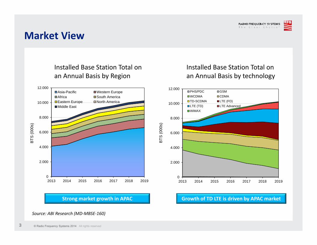
Market View
0
2.000
4.000
6.000
8.000
10.000
12.000
2013 2014 2015 2016 2017 2018 2019
BT
S (
000s
)
Asia-Pacific Western EuropeAfrica South AmericaEastern Europe North AmericaMiddle East
Installed Base Station Total on
an Annual Basis by technology
0
2.000
4.000
6.000
8.000
10.000
12.000
2013 2014 2015 2016 2017 2018 2019
BT
S (
000s
)
PHS/PDC GSM
WCDMA CDMA
TD-SCDMA LTE (FD)
LTE (TD) LTE Advanced
WiMAX
Installed Base Station Total on
an Annual Basis by Region
Strong market growth in APAC Growth of TD LTE is driven by APAC market
Source: ABI Research (MD-MBSE-160)
© Radio Frequency Systems 2014 All rights reserved4
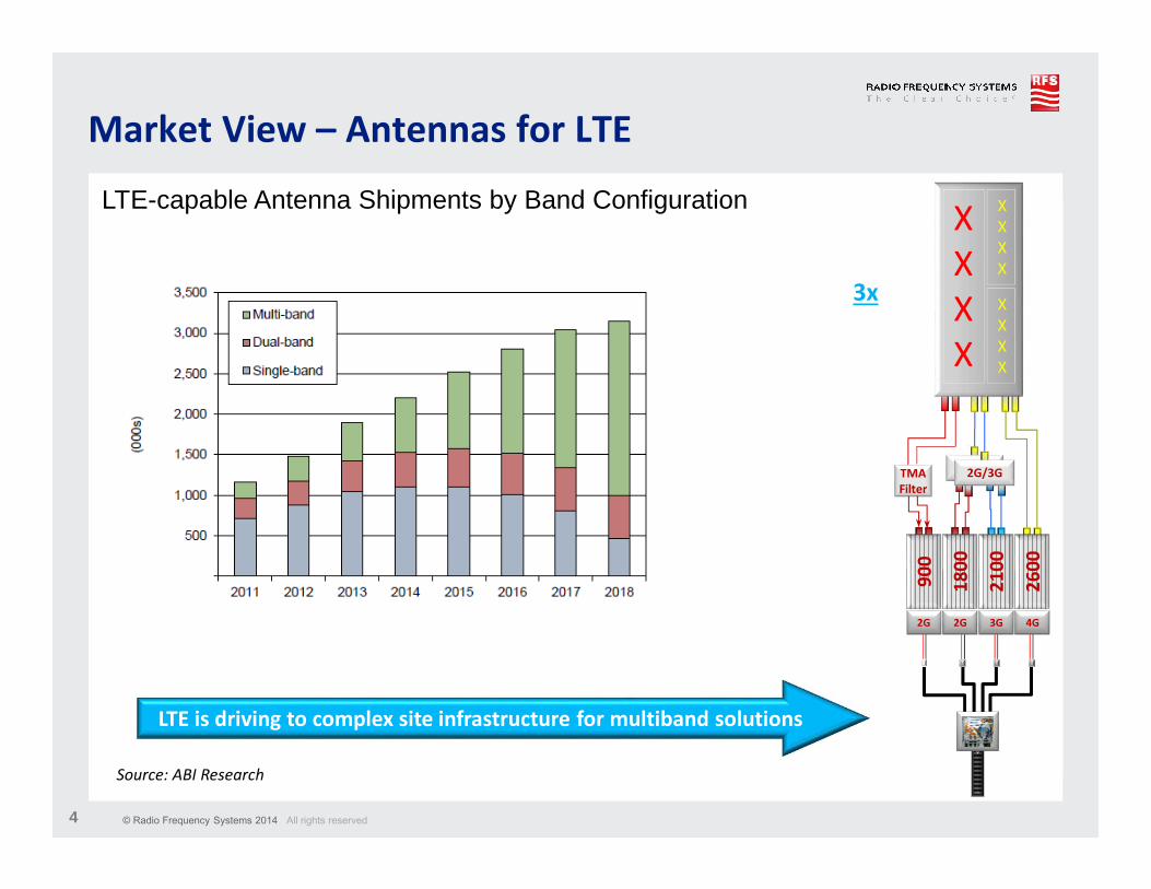
Market View – Antennas for LTE
LTE-capable Antenna Shipments by Band Configuration
18
00
26
00
21
00
90
0
2G 2G 3G 4G
X
X
X
X
X
X
X
X
X
X
X
X
2G/3G2G/3GTMA
Filter
LTE is driving to complex site infrastructure for multiband solutions
3x
Source: ABI Research
© Radio Frequency Systems 2014 All rights reserved5
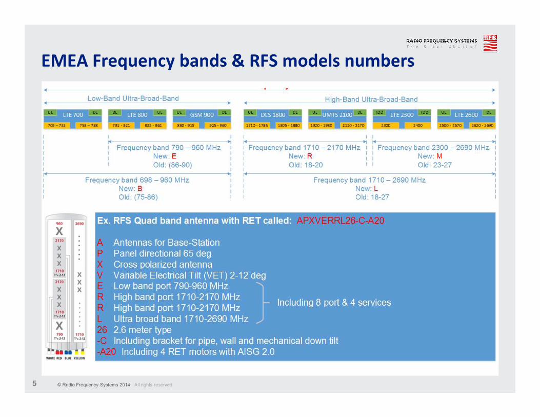
EMEA Frequency bands & RFS models numbers
© Radio Frequency Systems 2014 All rights reserved6
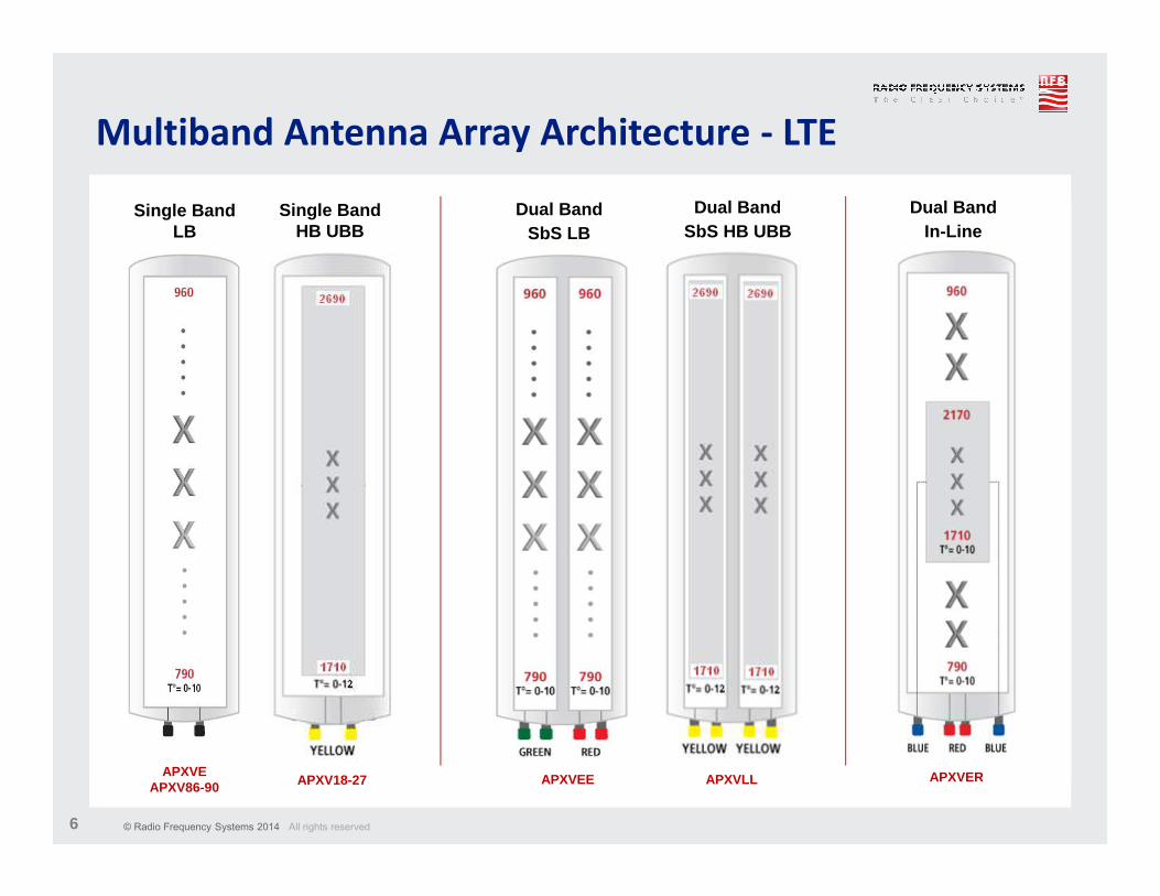
Multiband Antenna Array Architecture - LTE
Single BandHB UBB
Dual BandSbS LB
Dual BandIn-Line
Single BandLB
Dual BandSbS HB UBB
APXVEAPXV86-90 APXV18-27 APXVEE APXVLL APXVER
© Radio Frequency Systems 2014 All rights reserved7
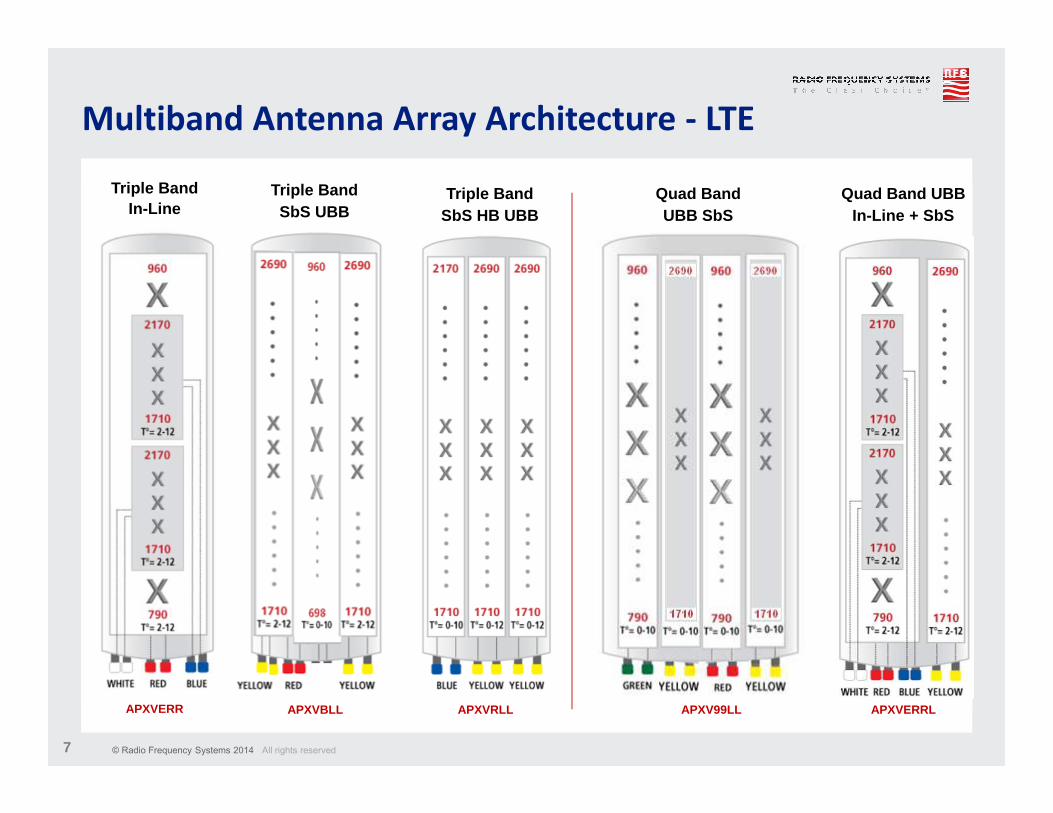
Multiband Antenna Array Architecture - LTE
Triple BandSbS UBB
Triple BandIn-Line
Quad Band UBBIn-Line + SbS
Triple BandSbS HB UBB
APXVERR APXVBLL APXVRLL APXVERRL
Quad BandUBB SbS
APXV99LL
© Radio Frequency Systems 2014 All rights reserved8
RFS Antenna key features
� Ultra Broad Band High Gain antennas with excellent performance over complete operating band: 790 – 960 MHz and 1710 – 2690 MHz
698 – 960 MHz and 1710 – 2690 MHz in 2014
� High stability of electrical performance over complete operating frequency band and tilt range due to separate phase shifter per dipole
� Broad tilt range for dense urban applications 0-12°
� Advanced upper side lobe suppression (USLS >17 dB in full UBB) resulting into maintained isolation with neighboring cells in high tilt range
� Long term stable PIM performance due to non metallic materials in VET system
� Reduce tower load due to optimized aerodynamic antenna shape“Wind Master” trade Mark
© Radio Frequency Systems 2014 All rights reserved9
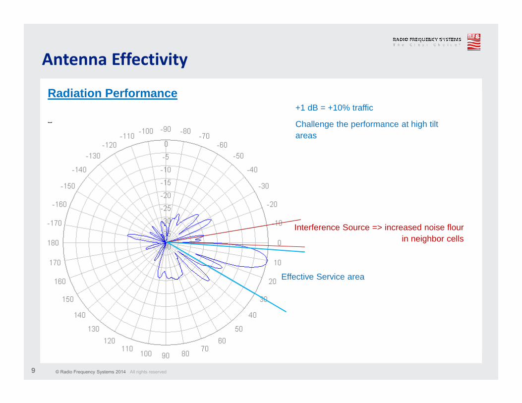
Antenna Effectivity
Interference Source => increased noise flour in neighbor cells
Radiation Performance
Effective Service area
+1 dB = +10% traffic
Challenge the performance at high tilt areas
© Radio Frequency Systems 2014 All rights reserved10
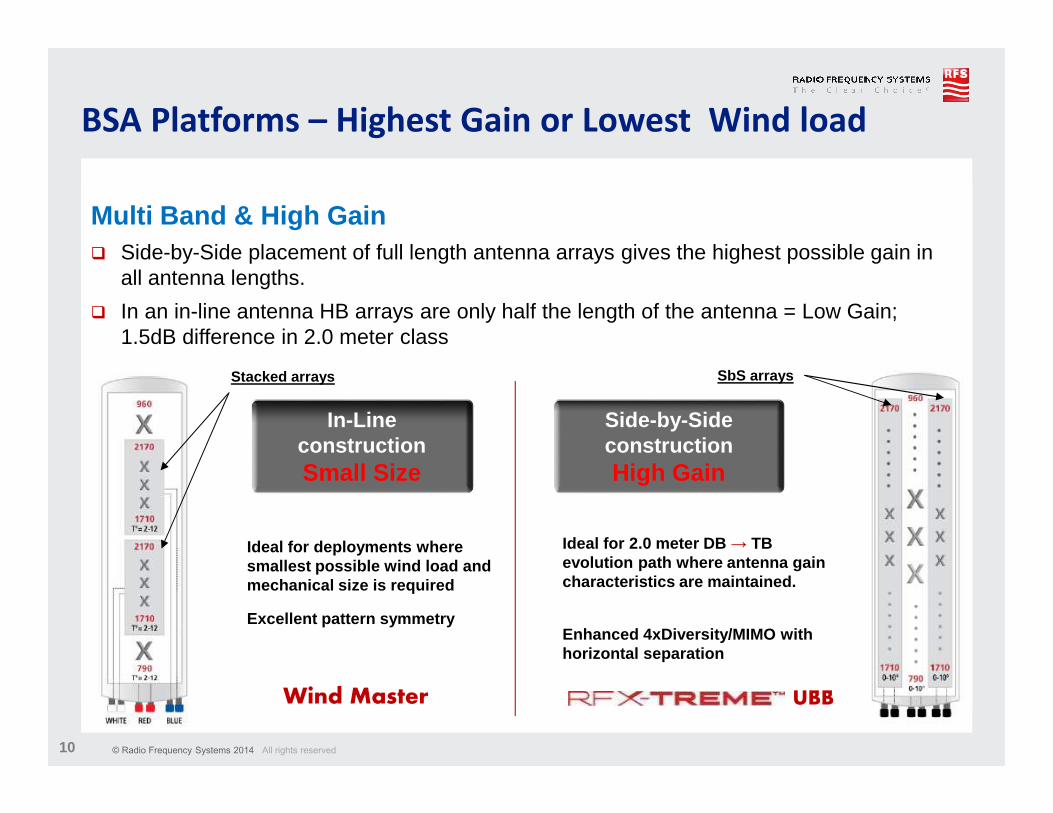
BSA Platforms – Highest Gain or Lowest Wind load
Multi Band & High Gain� Side-by-Side placement of full length antenna arrays gives the highest possible gain in
all antenna lengths.
� In an in-line antenna HB arrays are only half the length of the antenna = Low Gain; 1.5dB difference in 2.0 meter class
UBB
Ideal for 2.0 meter DB → TB evolution path where antenna gain characteristics are maintained.
Enhanced 4xDiversity/MIMO with horizontal separation
Ideal for deployments where smallest possible wind load and mechanical size is required
Excellent pattern symmetry
Side-by-SideconstructionHigh Gain
In-Line constructionSmall Size
Stacked arrays SbS arrays
Wind Master
© Radio Frequency Systems 2014 All rights reserved11
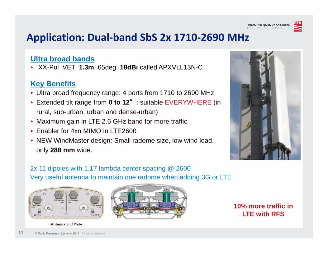
Application: Dual-band SbS 2x 1710-2690 MHz
Ultra broad bands• XX-Pol VET 1.3m 65deg 18dBi called APXVLL13N-C
Key Benefits• Ultra broad frequency range: 4 ports from 1710 to 2690 MHz• Extended tilt range from 0 to 12°°°°: suitable EVERYWHERE (in
rural, sub-urban, urban and dense-urban)• Maximum gain in LTE 2.6 GHz band for more traffic• Enabler for 4xn MIMO in LTE2600• NEW WindMaster design: Small radome size, low wind load,
only 288 mm wide.
2x 11 dipoles with 1.17 lambda center spacing @ 2600 Very useful antenna to maintain one radome when adding 3G or LTE
10% more traffic in LTE with RFS
© Radio Frequency Systems 2014 All rights reserved12
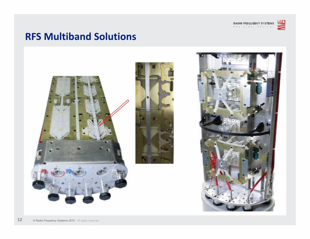
RFS Multiband Solutions

© Radio Frequency Systems 2014 All rights reserved13
Application: Triple Band 790-960 / 2x 1710-2170
Triple Band XXX-pol VET• XXX-pol VET 2.6m 65deg 17.5 dBi called APXVERR26-C
Key Benefits• Extended band to LTE 800• High Gain: A direct replacement for site upgrade• Omni shape Radome – Extreme low wind load < 600N• Broad tilt range: 2 to 12 deg• Low width 28 cm
WindMaster TM
• Optimized radome shape • Easy access to connectors • color code on connectors• Space for RET and indicator
© Radio Frequency Systems 2014 All rights reserved14
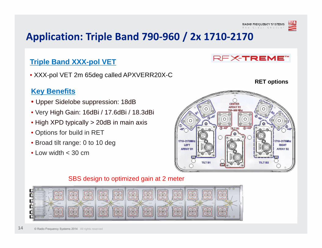
Application: Triple Band 790-960 / 2x 1710-2170
Triple Band XXX-pol VET
• XXX-pol VET 2m 65deg called APXVERR20X-C
Key Benefits• Upper Sidelobe suppression: 18dB
• Very High Gain: 16dBi / 17.6dBi / 18.3dBi
• High XPD typically > 20dB in main axis
• Options for build in RET
• Broad tilt range: 0 to 10 deg
• Low width < 30 cm
SBS design to optimized gain at 2 meter
RET options
© Radio Frequency Systems 2014 All rights reserved15
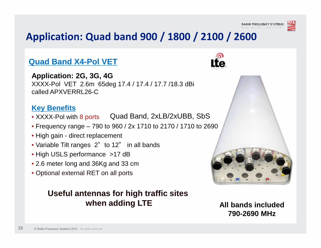
Application: Quad band 900 / 1800 / 2100 / 2600
Quad Band X4-Pol VET
Application: 2G, 3G, 4GXXXX-Pol VET 2.6m 65deg 17.4 / 17.4 / 17.7 /18.3 dBi called APXVERRL26-C
Key Benefits• XXXX-Pol with 8 ports• Frequency range – 790 to 960 / 2x 1710 to 2170 / 1710 to 2690• High gain - direct replacement • Variable Tilt ranges 2°to 12° in all bands• High USLS performance >17 dB• 2.6 meter long and 36Kg and 33 cm• Optional external RET on all ports
Useful antennas for high traffic sites when adding LTE All bands included
790-2690 MHz
Quad Band, 2xLB/2xUBB, SbS
© Radio Frequency Systems 2014 All rights reserved16
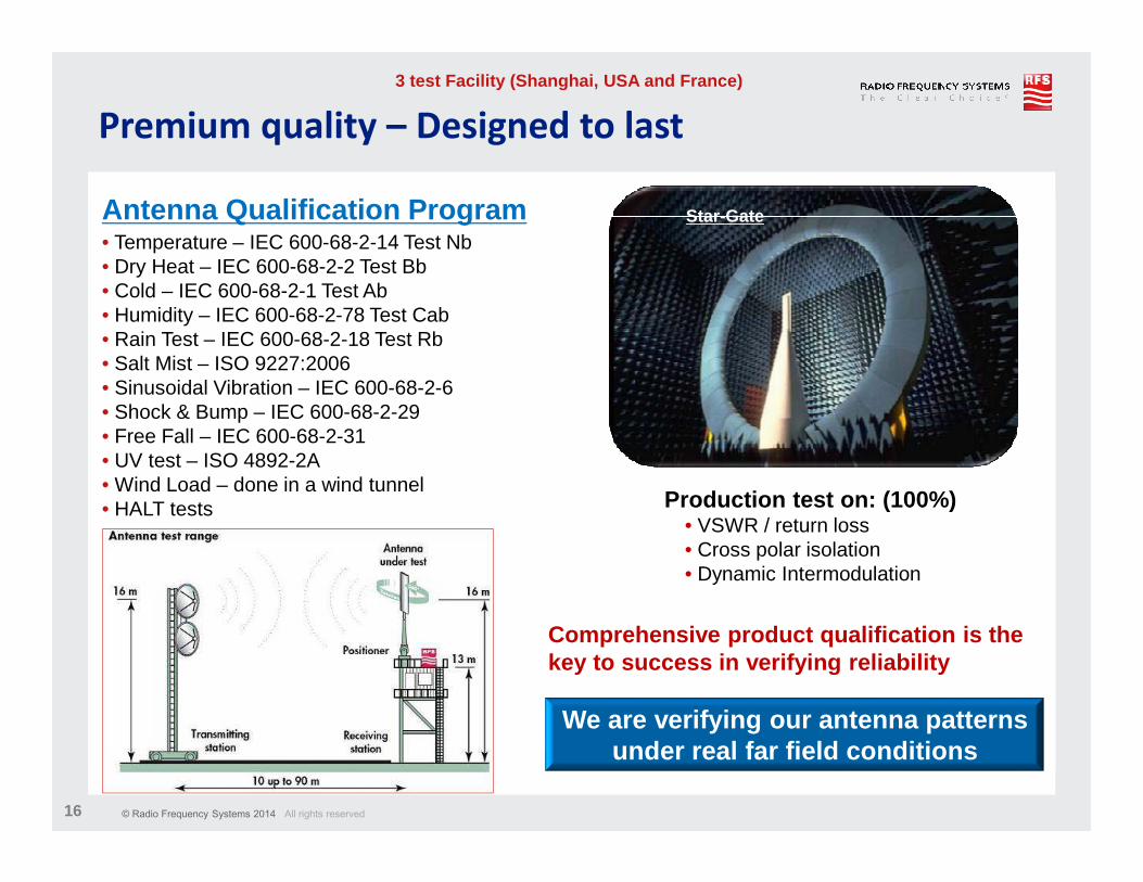
Premium quality – Designed to last
Antenna Qualification Program• Temperature – IEC 600-68-2-14 Test Nb• Dry Heat – IEC 600-68-2-2 Test Bb• Cold – IEC 600-68-2-1 Test Ab• Humidity – IEC 600-68-2-78 Test Cab• Rain Test – IEC 600-68-2-18 Test Rb• Salt Mist – ISO 9227:2006• Sinusoidal Vibration – IEC 600-68-2-6• Shock & Bump – IEC 600-68-2-29• Free Fall – IEC 600-68-2-31• UV test – ISO 4892-2A• Wind Load – done in a wind tunnel• HALT tests
Comprehensive product qualification is the key to success in verifying reliability
Star-Gate
3 test Facility (Shanghai, USA and France)
We are verifying our antenna patterns under real far field conditions
Production test on: (100%)• VSWR / return loss• Cross polar isolation• Dynamic Intermodulation
© Radio Frequency Systems 2014 All rights reserved17
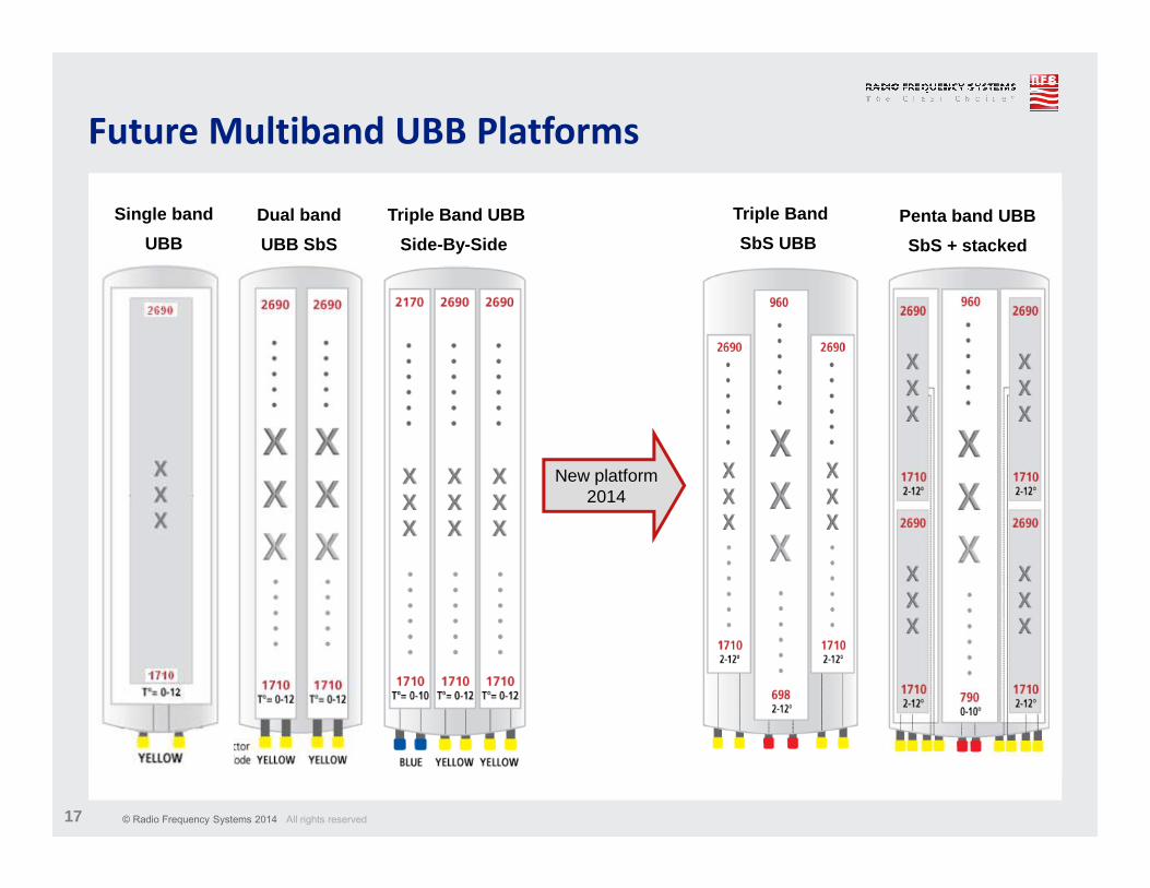
Future Multiband UBB Platforms
Dual band
UBB SbS
Triple Band
SbS UBB
Penta band UBB
SbS + stacked
Single band
UBB
Triple Band UBB
Side-By-Side
New platform2014
© Radio Frequency Systems 2014 All rights reserved18
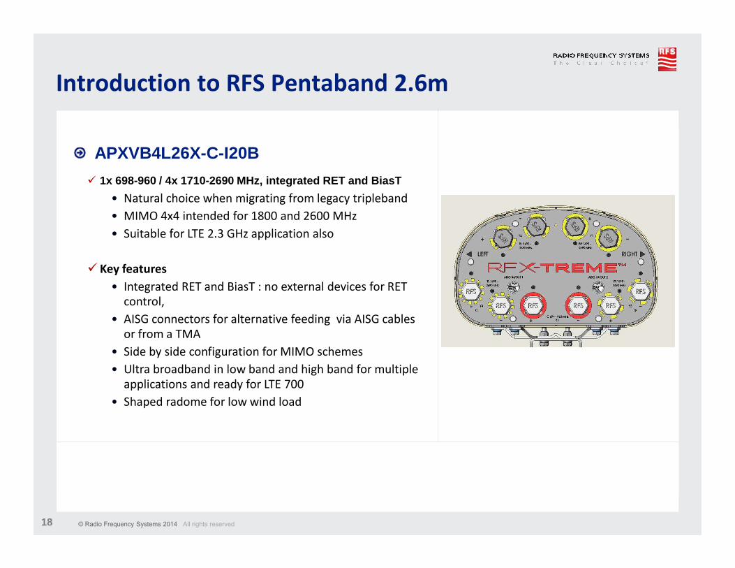
� 1x 698-960 / 4x 1710-2690 MHz, integrated RET and Bi asT
• Natural choice when migrating from legacy tripleband
• MIMO 4x4 intended for 1800 and 2600 MHz
• Suitable for LTE 2.3 GHz application also
� Key features
• Integrated RET and BiasT : no external devices for RET
control,
• AISG connectors for alternative feeding via AISG cables
or from a TMA
• Side by side configuration for MIMO schemes
• Ultra broadband in low band and high band for multiple
applications and ready for LTE 700
• Shaped radome for low wind load
Introduction to RFS Pentaband 2.6m
APXVB4L26X-C-I20B
© Radio Frequency Systems 2014 All rights reserved19
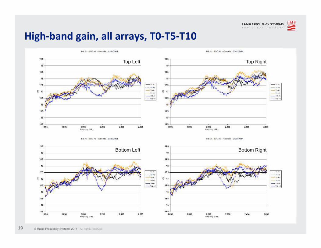
High-band gain, all arrays, T0-T5-T10
Top Left Top Right
Bottom Left Bottom Right
© Radio Frequency Systems 2014 All rights reserved20
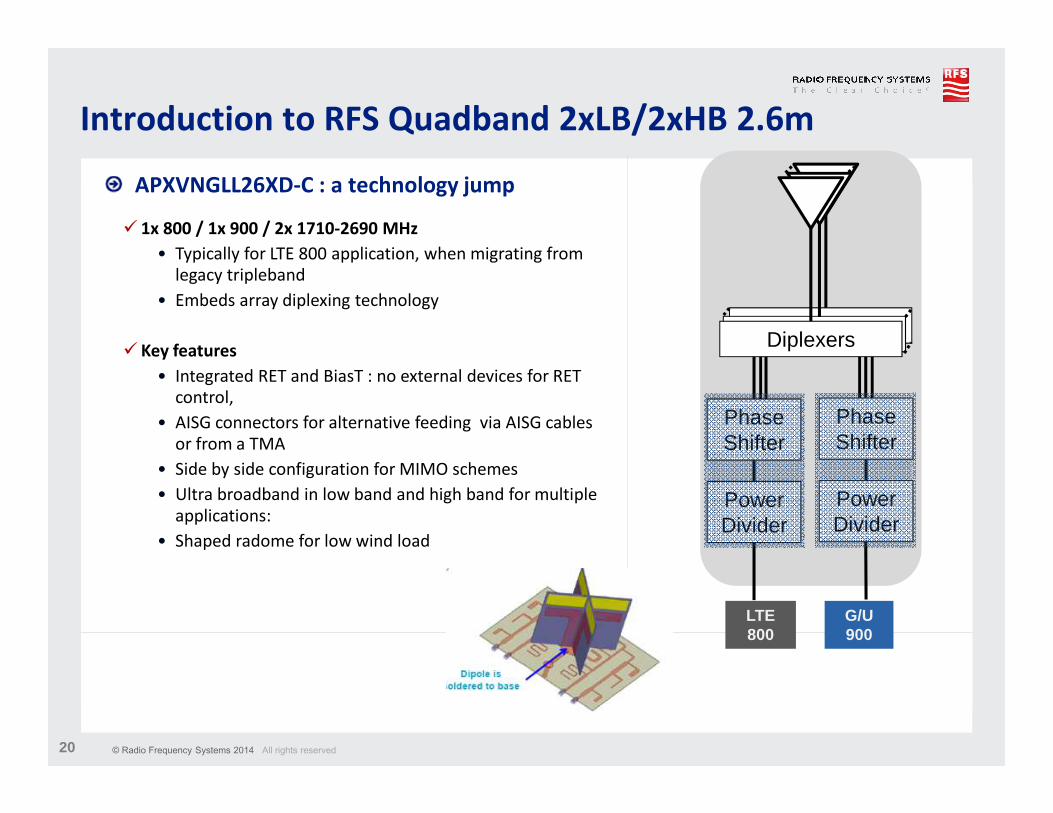
� 1x 800 / 1x 900 / 2x 1710-2690 MHz
• Typically for LTE 800 application, when migrating from
legacy tripleband
• Embeds array diplexing technology
� Key features
• Integrated RET and BiasT : no external devices for RET
control,
• AISG connectors for alternative feeding via AISG cables
or from a TMA
• Side by side configuration for MIMO schemes
• Ultra broadband in low band and high band for multiple
applications:
• Shaped radome for low wind load
Introduction to RFS Quadband 2xLB/2xHB 2.6m
APXVNGLL26XD-C : a technology jump
Diplexers
Phase Shifter
Power Divider
Power Divider
Phase Shifter
LTE 800
G/U 900
© Radio Frequency Systems 2014 All rights reserved21
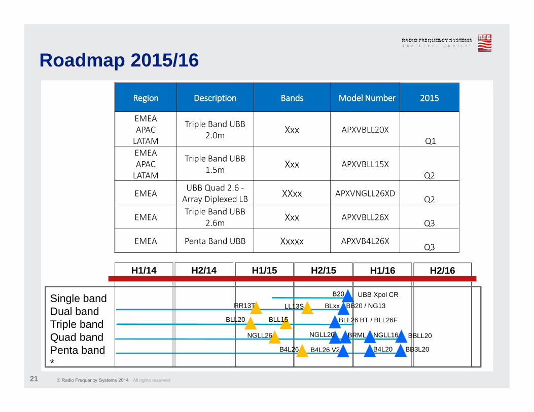
Roadmap 2015/16
RegionRegionRegionRegion DescriptionDescriptionDescriptionDescription BandsBandsBandsBands Model NumberModel NumberModel NumberModel Number 2015201520152015
EMEA
APAC
LATAM
Triple Band UBB
2.0mXxx APXVBLL20X
Q1
EMEA
APAC
LATAM
Triple Band UBB
1.5mXxx APXVBLL15X
Q2
EMEAUBB Quad 2.6 -
Array Diplexed LBXXxx APXVNGLL26XD
Q2
EMEATriple Band UBB
2.6mXxx APXVBLL26X
Q3
EMEA Penta Band UBB Xxxxx APXVB4L26X Q3
H1/14 H2/14 H2/15H1/15 H2/16H1/16
Single bandDual bandTriple bandQuad bandPenta band*
B20 UBB Xpol CR
BLL20 BLL15
RR13T
NGLL26
B4L26
BLL26 BT / BLL26F
BRML
B4L26 V2 BB3L20
NGLL16NGLL20
LL13S BLxx BB20 / NG13
B4L20
BBLL20
© Radio Frequency Systems 2014 All rights reserved22
BSA EMEA - Highlights 2014
Tangible capacity increase on-going
Top 5 major wins
• Big success with KPN Netherlands
2014/15: Wind Master antennas
• We are listed as one of the two major
suppliers for BSA at Telenor
• Increase our BSA market share in Russia
by 300%
• First success with NSN in Africa
• Positioning our quad band in Orange
Romania
© Radio Frequency Systems 2014 All rights reserved23
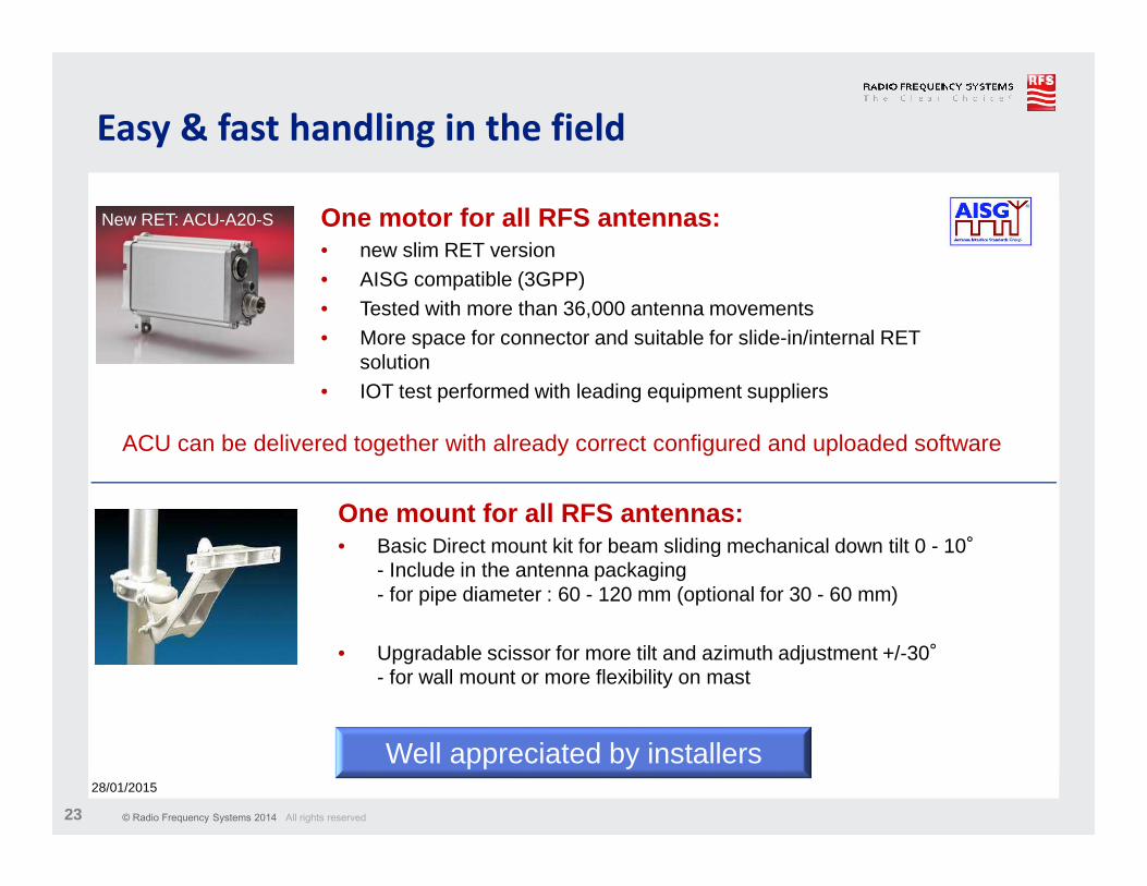
Easy & fast handling in the field
One motor for all RFS antennas: • new slim RET version• AISG compatible (3GPP) • Tested with more than 36,000 antenna movements• More space for connector and suitable for slide-in/internal RET
solution• IOT test performed with leading equipment suppliers
New RET: ACU-A20-S
28/01/2015
ACU can be delivered together with already correct configured and uploaded software
One mount for all RFS antennas: • Basic Direct mount kit for beam sliding mechanical down tilt 0 - 10°
- Include in the antenna packaging- for pipe diameter : 60 - 120 mm (optional for 30 - 60 mm)
• Upgradable scissor for more tilt and azimuth adjustment +/-30°- for wall mount or more flexibility on mast
Well appreciated by installers
© Radio Frequency Systems 2014 All rights reserved24
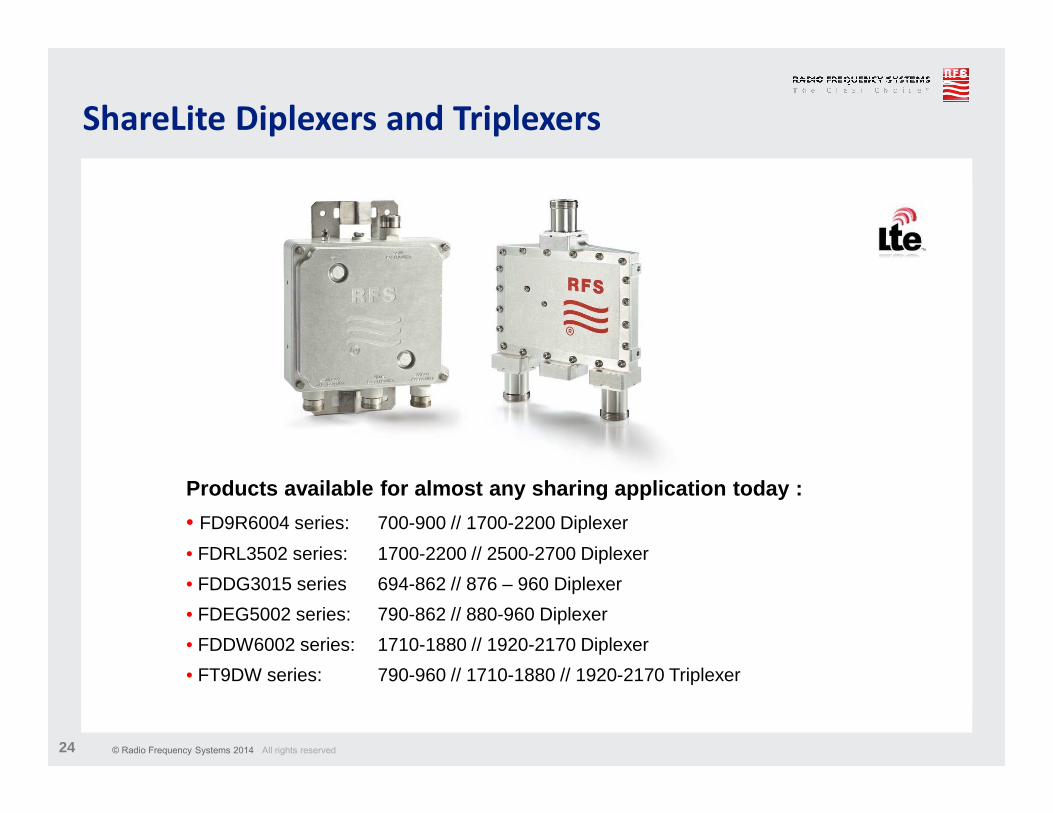
Products available for almost any sharing applicati on today :
• FD9R6004 series: 700-900 // 1700-2200 Diplexer
• FDRL3502 series: 1700-2200 // 2500-2700 Diplexer
• FDDG3015 series 694-862 // 876 – 960 Diplexer
• FDEG5002 series: 790-862 // 880-960 Diplexer
• FDDW6002 series: 1710-1880 // 1920-2170 Diplexer
• FT9DW series: 790-960 // 1710-1880 // 1920-2170 Triplexer
ShareLite Diplexers and Triplexers
© Radio Frequency Systems 2014 All rights reserved25
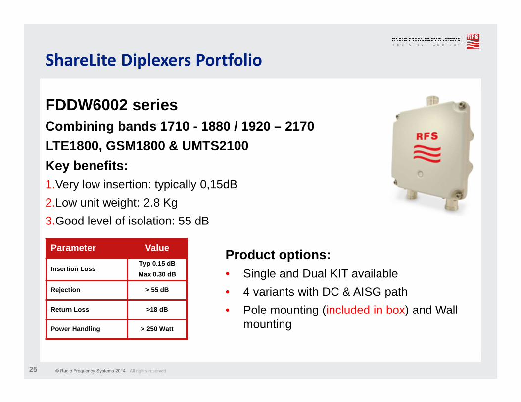
FDDW6002 series Combining bands 1710 - 1880 / 1920 – 2170
LTE1800, GSM1800 & UMTS2100
Key benefits:1.Very low insertion: typically 0,15dB
2.Low unit weight: 2.8 Kg
3.Good level of isolation: 55 dB
ShareLite Diplexers Portfolio
Parameter Value
Insertion LossTyp 0.15 dB
Max 0.30 dB
Rejection > 55 dB
Return Loss >18 dB
Power Handling > 250 Watt
Product options:• Single and Dual KIT available
• 4 variants with DC & AISG path
• Pole mounting (included in box) and Wall mounting
© Radio Frequency Systems 2014 All rights reserved26 © Radio Frequency Systems 2014. All rights reserved
Performance
Our focus
Quality
InnovationCustomer
Care
RFS Motivation
g{tÇ~ lÉâ