Embed Size (px)
Citation preview
20
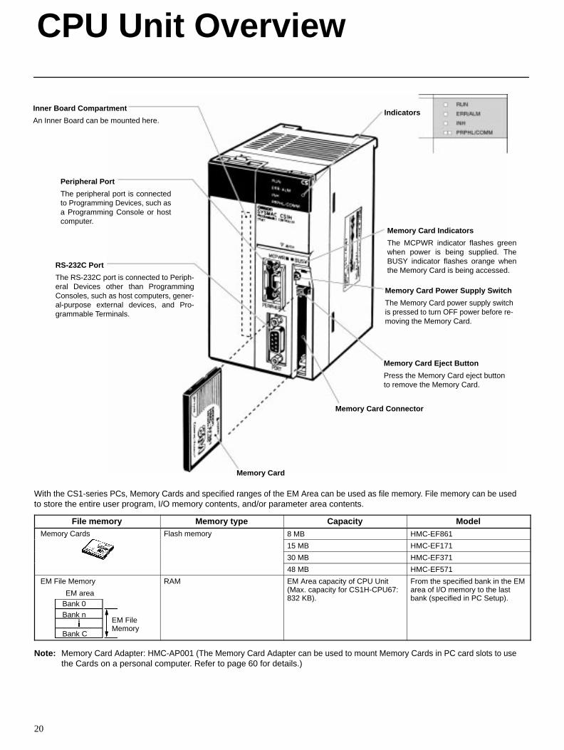
Inner Board Compartment
An Inner Board can be mounted here.
Peripheral Port
The peripheral port is connectedto Programming Devices, such asa Programming Console or hostcomputer.
RS-232C Port
The RS-232C port is connected to Periph-eral Devices other than ProgrammingConsoles, such as host computers, gener-al-purpose external devices, and Pro-grammable Terminals.
Indicators
Memory Card Indicators
The MCPWR indicator flashes greenwhen power is being supplied. TheBUSY indicator flashes orange whenthe Memory Card is being accessed.
Memory Card Power Supply Switch
The Memory Card power supply switchis pressed to turn OFF power before re-moving the Memory Card.
Memory Card Eject Button
Press the Memory Card eject buttonto remove the Memory Card.
Memory Card Connector
Memory Card
With the CS1-series PCs, Memory Cards and specified ranges of the EM Area can be used as file memory. File memory can be usedto store the entire user program, I/O memory contents, and/or parameter area contents.
File memory Memory type Capacity ModelMemory Cards Flash memory 8 MB HMC-EF861e o y Ca ds as e o y
15 MB HMC-EF171
30 MB HMC-EF371
48 MB HMC-EF571
EM File Memory
EM area
EM File Memory
Bank 0
Bank n
Bank C
RAM EM Area capacity of CPU Unit(Max. capacity for CS1H-CPU67:832 KB).
From the specified bank in the EMarea of I/O memory to the lastbank (specified in PC Setup).
Note: Memory Card Adapter: HMC-AP001 (The Memory Card Adapter can be used to mount Memory Cards in PC card slots to usethe Cards on a personal computer. Refer to page 60 for details.)
CPU Unit Overview
21
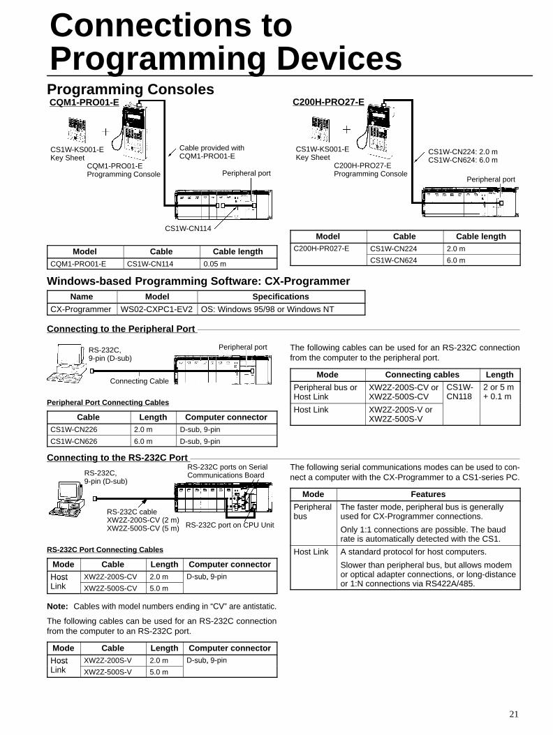
Programming Consoles
CQM1-PRO01-EProgramming Console
CS1W-KS001-EKey Sheet
CS1W-CN114
Cable provided withCQM1-PRO01-E
Peripheral port
CQM1-PRO01-E
Model Cable Cable lengthCQM1-PRO01-E CS1W-CN114 0.05 m
CS1W-KS001-EKey Sheet
C200H-PRO27-EProgramming Console
CS1W-CN224: 2.0 mCS1W-CN624: 6.0 m
Peripheral port
C200H-PRO27-E
Model Cable Cable lengthC200H-PR027-E CS1W-CN224 2.0 mC 00 0
CS1W-CN624 6.0 m
Windows-based Programming Software: CX-ProgrammerName Model Specifications
CX-Programmer WS02-CXPC1-EV2 OS: Windows 95/98 or Windows NT
Connecting to the Peripheral Port
RS-232C,9-pin (D-sub)
Peripheral port
Connecting Cable
Peripheral Port Connecting Cables
Cable Length Computer connectorCS1W-CN226 2.0 m D-sub, 9-pin
CS1W-CN626 6.0 m D-sub, 9-pin
The following cables can be used for an RS-232C connectionfrom the computer to the peripheral port.
Mode Connecting cables Length
Peripheral bus or Host Link
XW2Z-200S-CV orXW2Z-500S-CV
CS1W-CN118
2 or 5 m+ 0.1 m
Host Link XW2Z-200S-V orXW2Z-500S-V
Connecting to the RS-232C Port
RS-232C,9-pin (D-sub)
RS-232C port on CPU Unit
RS-232C cableXW2Z-200S-CV (2 m)XW2Z-500S-CV (5 m)
RS-232C ports on SerialCommunications Board
RS-232C Port Connecting Cables
Mode Cable Length Computer connector
Host XW2Z-200S-CV 2.0 m D-sub, 9-pinHostLink XW2Z-500S-CV 5.0 m
sub, 9
Note: Cables with model numbers ending in “CV” are antistatic.
The following cables can be used for an RS-232C connectionfrom the computer to an RS-232C port.
Mode Cable Length Computer connectorHost XW2Z-200S-V 2.0 m D-sub, 9-pinHostLink XW2Z-500S-V 5.0 m
sub, 9
The following serial communications modes can be used to con-nect a computer with the CX-Programmer to a CS1-series PC.
Mode Features
Peripheralbus
The faster mode, peripheral bus is generallyused for CX-Programmer connections.
Only 1:1 connections are possible. The baudrate is automatically detected with the CS1.
Host Link A standard protocol for host computers.
Slower than peripheral bus, but allows modemor optical adapter connections, or long-distanceor 1:N connections via RS422A/485.
Connections toProgramming Devices
22
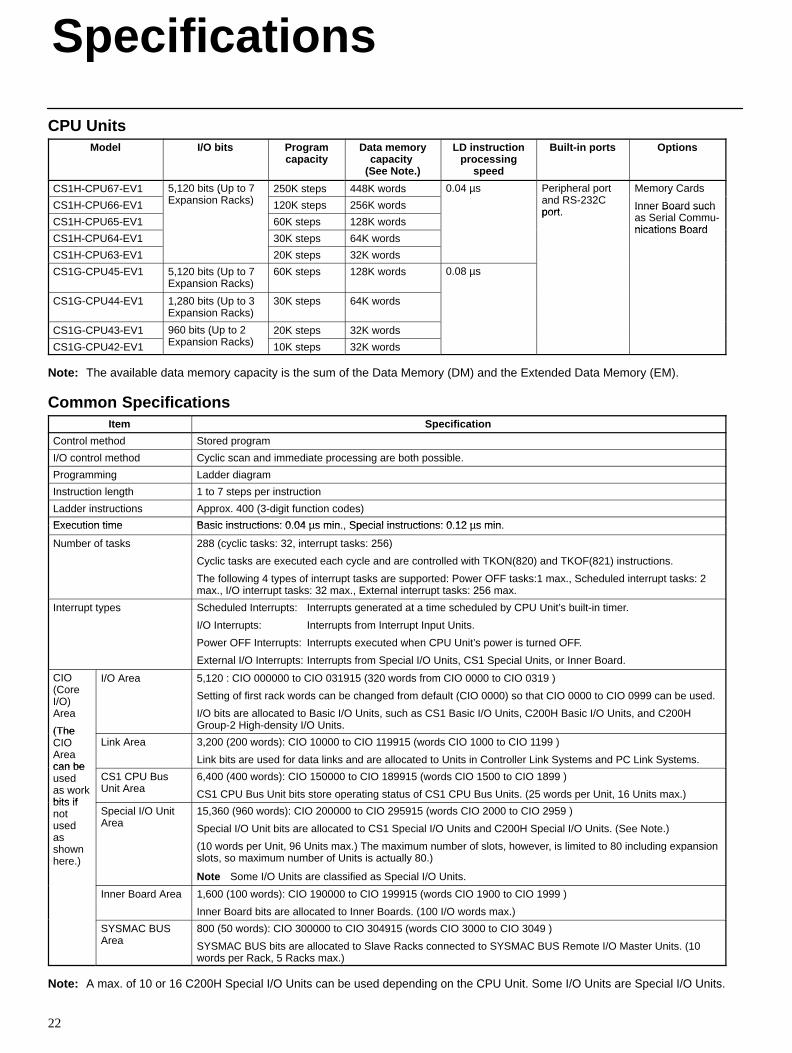
CPU UnitsModel I/O bits Program
capacityData memory
capacity (See Note.)
LD instructionprocessing
speed
Built-in ports Options
CS1H-CPU67-EV1 5,120 bits (Up to 7E i R k )
250K steps 448K words 0.04 µs Peripheral portd RS 232C
Memory Cards
CS1H-CPU66-EV1
5, 0 b s (U oExpansion Racks) 120K steps 256K words
0 0 µs e e a oand RS-232Cport
e o y Ca ds
Inner Board such
CS1H-CPU65-EV1 60K steps 128K wordsport. Inner Board such
as Serial Commu-nications Board
CS1H-CPU64-EV1 30K steps 64K wordsnications Board
CS1H-CPU63-EV1 20K steps 32K words
CS1G-CPU45-EV1 5,120 bits (Up to 7Expansion Racks)
60K steps 128K words 0.08 µs
CS1G-CPU44-EV1 1,280 bits (Up to 3Expansion Racks)
30K steps 64K words
CS1G-CPU43-EV1 960 bits (Up to 2E i R k )
20K steps 32K words
CS1G-CPU42-EV1
960 b s (U oExpansion Racks) 10K steps 32K words
Note: The available data memory capacity is the sum of the Data Memory (DM) and the Extended Data Memory (EM).
Common SpecificationsItem Specification
Control method Stored program
I/O control method Cyclic scan and immediate processing are both possible.
Programming Ladder diagram
Instruction length 1 to 7 steps per instruction
Ladder instructions Approx. 400 (3-digit function codes)
Execution time Basic instructions: 0 04 µs min Special instructions: 0 12 µs minExecution time Basic instructions: 0.04 µs min., Special instructions: 0.12 µs min.
Number of tasks 288 (cyclic tasks: 32, interrupt tasks: 256)
Cyclic tasks are executed each cycle and are controlled with TKON(820) and TKOF(821) instructions.
The following 4 types of interrupt tasks are supported: Power OFF tasks:1 max., Scheduled interrupt tasks: 2max., I/O interrupt tasks: 32 max., External interrupt tasks: 256 max.
Interrupt types Scheduled Interrupts: Interrupts generated at a time scheduled by CPU Unit’s built-in timer.
I/O Interrupts: Interrupts from Interrupt Input Units.
Power OFF Interrupts: Interrupts executed when CPU Unit’s power is turned OFF.
External I/O Interrupts: Interrupts from Special I/O Units, CS1 Special Units, or Inner Board.
CIO(CoreI/O)Area
(The
I/O Area 5,120 : CIO 000000 to CIO 031915 (320 words from CIO 0000 to CIO 0319 )
Setting of first rack words can be changed from default (CIO 0000) so that CIO 0000 to CIO 0999 can be used.
I/O bits are allocated to Basic I/O Units, such as CS1 Basic I/O Units, C200H Basic I/O Units, and C200HGroup-2 High-density I/O Units.(The
CIOAreacan be
Link Area 3,200 (200 words): CIO 10000 to CIO 119915 (words CIO 1000 to CIO 1199 )
Link bits are used for data links and are allocated to Units in Controller Link Systems and PC Link Systems.can beusedas workbits if
CS1 CPU BusUnit Area
6,400 (400 words): CIO 150000 to CIO 189915 (words CIO 1500 to CIO 1899 )
CS1 CPU Bus Unit bits store operating status of CS1 CPU Bus Units. (25 words per Unit, 16 Units max.)bits ifnotusedasshownhere.)
Special I/O UnitArea
15,360 (960 words): CIO 200000 to CIO 295915 (words CIO 2000 to CIO 2959 )
Special I/O Unit bits are allocated to CS1 Special I/O Units and C200H Special I/O Units. (See Note.)
(10 words per Unit, 96 Units max.) The maximum number of slots, however, is limited to 80 including expansionslots, so maximum number of Units is actually 80.)
Note Some I/O Units are classified as Special I/O Units.
Inner Board Area 1,600 (100 words): CIO 190000 to CIO 199915 (words CIO 1900 to CIO 1999 )
Inner Board bits are allocated to Inner Boards. (100 I/O words max.)
SYSMAC BUSArea
800 (50 words): CIO 300000 to CIO 304915 (words CIO 3000 to CIO 3049 )
SYSMAC BUS bits are allocated to Slave Racks connected to SYSMAC BUS Remote I/O Master Units. (10words per Rack, 5 Racks max.)
Note: A max. of 10 or 16 C200H Special I/O Units can be used depending on the CPU Unit. Some I/O Units are Special I/O Units.
Specifications
Specifications
23
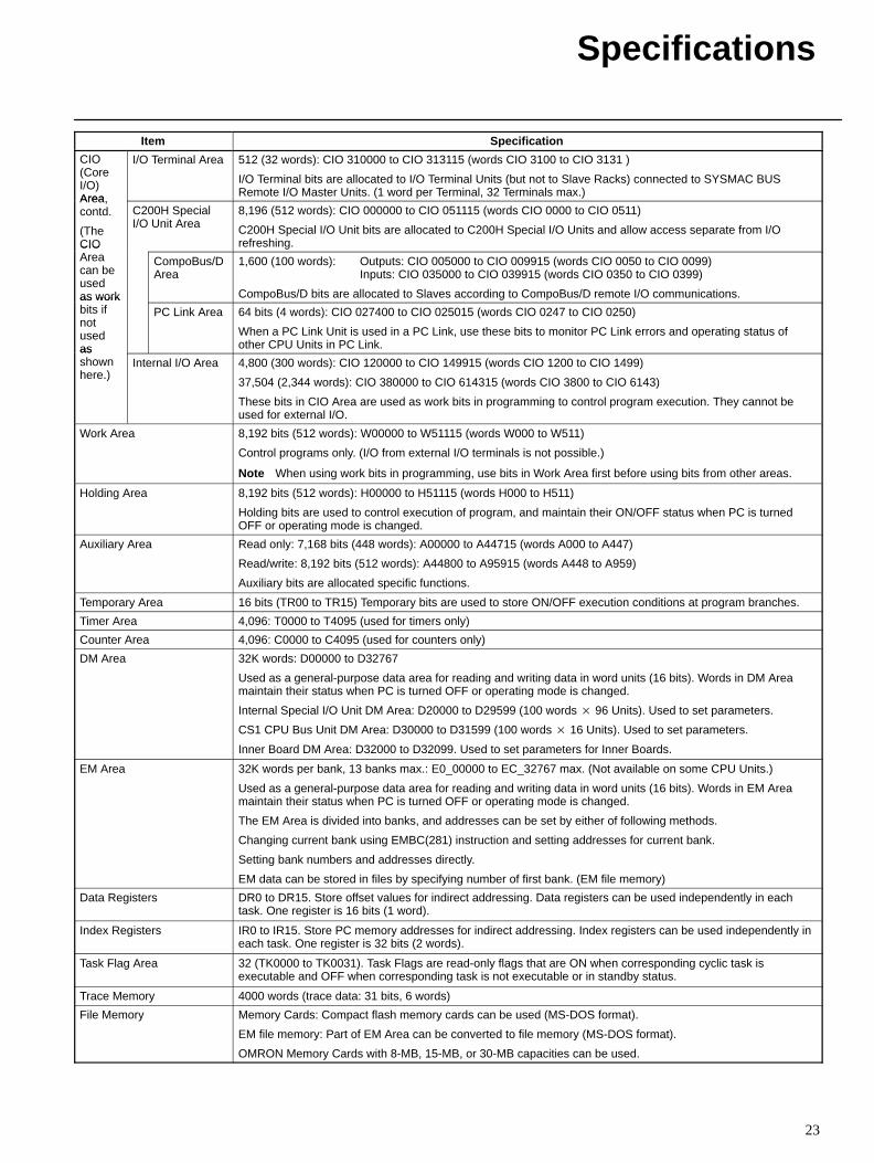
Item Specification
CIO(CoreI/O)Area
I/O Terminal Area 512 (32 words): CIO 310000 to CIO 313115 (words CIO 3100 to CIO 3131 )
I/O Terminal bits are allocated to I/O Terminal Units (but not to Slave Racks) connected to SYSMAC BUSRemote I/O Master Units. (1 word per Terminal, 32 Terminals max.)Area,
contd.
(TheCIO
C200H SpecialI/O Unit Area
8,196 (512 words): CIO 000000 to CIO 051115 (words CIO 0000 to CIO 0511)
C200H Special I/O Unit bits are allocated to C200H Special I/O Units and allow access separate from I/Orefreshing.CIO
Areacan beusedas work
CompoBus/DArea
1,600 (100 words): Outputs: CIO 005000 to CIO 009915 (words CIO 0050 to CIO 0099)Inputs: CIO 035000 to CIO 039915 (words CIO 0350 to CIO 0399)
CompoBus/D bits are allocated to Slaves according to CompoBus/D remote I/O communications.as workbits ifnotusedas
PC Link Area 64 bits (4 words): CIO 027400 to CIO 025015 (words CIO 0247 to CIO 0250)
When a PC Link Unit is used in a PC Link, use these bits to monitor PC Link errors and operating status ofother CPU Units in PC Link.as
shownhere.)
Internal I/O Area 4,800 (300 words): CIO 120000 to CIO 149915 (words CIO 1200 to CIO 1499)
37,504 (2,344 words): CIO 380000 to CIO 614315 (words CIO 3800 to CIO 6143)
These bits in CIO Area are used as work bits in programming to control program execution. They cannot beused for external I/O.
Work Area 8,192 bits (512 words): W00000 to W51115 (words W000 to W511)
Control programs only. (I/O from external I/O terminals is not possible.)
Note When using work bits in programming, use bits in Work Area first before using bits from other areas.
Holding Area 8,192 bits (512 words): H00000 to H51115 (words H000 to H511)
Holding bits are used to control execution of program, and maintain their ON/OFF status when PC is turnedOFF or operating mode is changed.
Auxiliary Area Read only: 7,168 bits (448 words): A00000 to A44715 (words A000 to A447)
Read/write: 8,192 bits (512 words): A44800 to A95915 (words A448 to A959)
Auxiliary bits are allocated specific functions.
Temporary Area 16 bits (TR00 to TR15) Temporary bits are used to store ON/OFF execution conditions at program branches.
Timer Area 4,096: T0000 to T4095 (used for timers only)
Counter Area 4,096: C0000 to C4095 (used for counters only)
DM Area 32K words: D00000 to D32767
Used as a general-purpose data area for reading and writing data in word units (16 bits). Words in DM Areamaintain their status when PC is turned OFF or operating mode is changed.
Internal Special I/O Unit DM Area: D20000 to D29599 (100 words 96 Units). Used to set parameters.
CS1 CPU Bus Unit DM Area: D30000 to D31599 (100 words 16 Units). Used to set parameters.
Inner Board DM Area: D32000 to D32099. Used to set parameters for Inner Boards.
EM Area 32K words per bank, 13 banks max.: E0_00000 to EC_32767 max. (Not available on some CPU Units.)
Used as a general-purpose data area for reading and writing data in word units (16 bits). Words in EM Areamaintain their status when PC is turned OFF or operating mode is changed.
The EM Area is divided into banks, and addresses can be set by either of following methods.
Changing current bank using EMBC(281) instruction and setting addresses for current bank.
Setting bank numbers and addresses directly.
EM data can be stored in files by specifying number of first bank. (EM file memory)
Data Registers DR0 to DR15. Store offset values for indirect addressing. Data registers can be used independently in eachtask. One register is 16 bits (1 word).
Index Registers IR0 to IR15. Store PC memory addresses for indirect addressing. Index registers can be used independently ineach task. One register is 32 bits (2 words).
Task Flag Area 32 (TK0000 to TK0031). Task Flags are read-only flags that are ON when corresponding cyclic task isexecutable and OFF when corresponding task is not executable or in standby status.
Trace Memory 4000 words (trace data: 31 bits, 6 words)
File Memory Memory Cards: Compact flash memory cards can be used (MS-DOS format).
EM file memory: Part of EM Area can be converted to file memory (MS-DOS format).
OMRON Memory Cards with 8-MB, 15-MB, or 30-MB capacities can be used.
Specifications
24
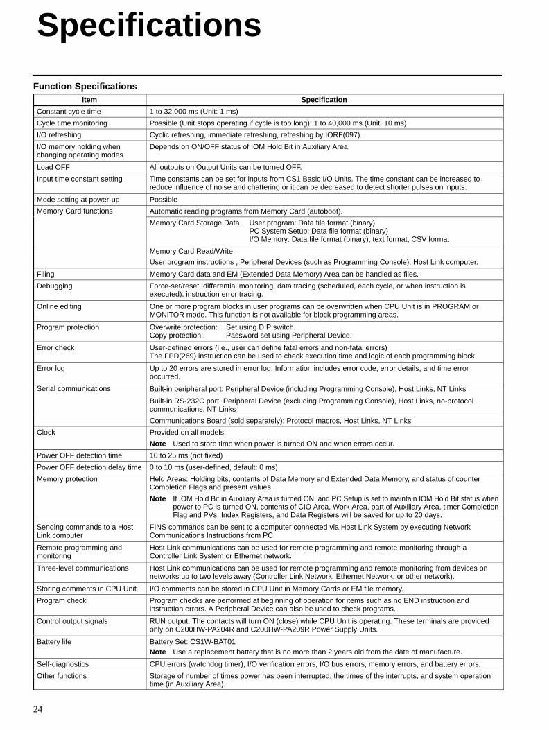
Function SpecificationsItem Specification
Constant cycle time 1 to 32,000 ms (Unit: 1 ms)
Cycle time monitoring Possible (Unit stops operating if cycle is too long): 1 to 40,000 ms (Unit: 10 ms)
I/O refreshing Cyclic refreshing, immediate refreshing, refreshing by IORF(097).
I/O memory holding whenchanging operating modes
Depends on ON/OFF status of IOM Hold Bit in Auxiliary Area.
Load OFF All outputs on Output Units can be turned OFF.
Input time constant setting Time constants can be set for inputs from CS1 Basic I/O Units. The time constant can be increased toreduce influence of noise and chattering or it can be decreased to detect shorter pulses on inputs.
Mode setting at power-up Possible
Memory Card functions Automatic reading programs from Memory Card (autoboot).e o y Ca d u c o s
Memory Card Storage Data User program: Data file format (binary)PC System Setup: Data file format (binary)I/O Memory: Data file format (binary), text format, CSV format
Memory Card Read/Write
User program instructions , Peripheral Devices (such as Programming Console), Host Link computer.
Filing Memory Card data and EM (Extended Data Memory) Area can be handled as files.
Debugging Force-set/reset, differential monitoring, data tracing (scheduled, each cycle, or when instruction isexecuted), instruction error tracing.
Online editing One or more program blocks in user programs can be overwritten when CPU Unit is in PROGRAM orMONITOR mode. This function is not available for block programming areas.
Program protection Overwrite protection: Set using DIP switch.Copy protection: Password set using Peripheral Device.
Error check User-defined errors (i.e., user can define fatal errors and non-fatal errors)The FPD(269) instruction can be used to check execution time and logic of each programming block.
Error log Up to 20 errors are stored in error log. Information includes error code, error details, and time erroroccurred.
Serial communications Built-in peripheral port: Peripheral Device (including Programming Console), Host Links, NT Links
Built-in RS-232C port: Peripheral Device (excluding Programming Console), Host Links, no-protocolcommunications, NT Links
Communications Board (sold separately): Protocol macros, Host Links, NT Links
Clock Provided on all models.
Note Used to store time when power is turned ON and when errors occur.
Power OFF detection time 10 to 25 ms (not fixed)
Power OFF detection delay time 0 to 10 ms (user-defined, default: 0 ms)
Memory protection Held Areas: Holding bits, contents of Data Memory and Extended Data Memory, and status of counterCompletion Flags and present values.
Note If IOM Hold Bit in Auxiliary Area is turned ON, and PC Setup is set to maintain IOM Hold Bit status whenpower to PC is turned ON, contents of CIO Area, Work Area, part of Auxiliary Area, timer CompletionFlag and PVs, Index Registers, and Data Registers will be saved for up to 20 days.
Sending commands to a HostLink computer
FINS commands can be sent to a computer connected via Host Link System by executing NetworkCommunications Instructions from PC.
Remote programming andmonitoring
Host Link communications can be used for remote programming and remote monitoring through aController Link System or Ethernet network.
Three-level communications Host Link communications can be used for remote programming and remote monitoring from devices onnetworks up to two levels away (Controller Link Network, Ethernet Network, or other network).
Storing comments in CPU Unit I/O comments can be stored in CPU Unit in Memory Cards or EM file memory.
Program check Program checks are performed at beginning of operation for items such as no END instruction andinstruction errors. A Peripheral Device can also be used to check programs.
Control output signals RUN output: The contacts will turn ON (close) while CPU Unit is operating. These terminals are providedonly on C200HW-PA204R and C200HW-PA209R Power Supply Units.
Battery life Battery Set: CS1W-BAT01Note Use a replacement battery that is no more than 2 years old from the date of manufacture.
Self-diagnostics CPU errors (watchdog timer), I/O verification errors, I/O bus errors, memory errors, and battery errors.
Other functions Storage of number of times power has been interrupted, the times of the interrupts, and system operationtime (in Auxiliary Area).
Specifications
25
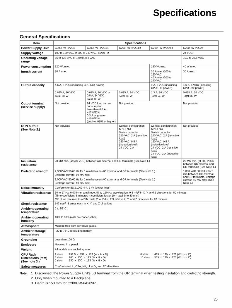
General SpecificationsItem Specifications
Power Supply Unit C200HW-PA204 C200HW-PA204S C200HW-PA204R C200HW-PA209R C200HW-PD024
Supply voltage 100 to 120 VAC or 200 to 240 VAC, 50/60 Hz 24 VDC
Operating voltagerange
85 to 132 VAC or 170 to 264 VAC 19.2 to 28.8 VDC
Power consumption 120 VA max. 180 VA max. 40 W max.
Inrush current 30 A max. 30 A max./100 to120 VAC40 A max./200 to240 VAC
30 A max.
Output capacity 4.6 A, 5 VDC (including CPU Unit power) 9 A, 5 VDC (includingCPU Unit power )
4.6 A, 5 VDC (includingCPU Unit power )
0.625 A, 26 VDCTotal: 30 W
0.625 A, 26 VDC or0.8 A, 24 VDCTotal: 30 W
0.625 A, 24 VDCTotal: 30 W
1.3 A, 26 VDCTotal: 45 W
0.625 A, 26 VDCTotal: 30 W
Output terminal(service supply)
Not provided 24 VDC load currentconsumptionLess than 0.3 A:+17%/11%0.3 A or greater:+10%/11%(Lot No. 0187 or higher)
Not provided Not provided
RUN output (See Note 2.)
Not provided Contact configuration:SPST-NOSwitch capacity: 250 VAC, 2 A (resistiveload)250 VAC, 0.5 A(induction load),24 VDC, 2 A
Contact configuration:SPST-NOSwitch capacity: 240 VAC, 2 A (resistiveload)120 VAC, 0.5 A(inductive load)24 VDC, 2 A (resistiveload)24 VDC, 2 A (inductiveload)
Not provided
Insulationresistance
20 MΩ min. (at 500 VDC) between AC external and GR terminals (See Note 1.) 20 MΩ min. (at 500 VDC)between DC external andGR terminals (See Note 1.)
Dielectric strength 2,300 VAC 50/60 Hz for 1 min between AC external and GR terminals (See Note 1.)Leakage current: 10 mA max.
1,000 VAC 50/60 Hz for 1min between DC externaland GR terminals leakage
1,000 VAC 50/60 Hz for 1 min between AC external and GR terminals (See Note 1.)Leakage current: 10 mA max.
and GR terminals, leakagecurrent: 10 mA max. (SeeNote 1.)
Noise immunity Conforms to IEC61000-4-4, 2 kV (power lines)
Vibration resistance 10 to 57 Hz, 0.075-mm amplitude, 57 to 150 Hz, acceleration: 9.8 m/s2 in X, Y, and Z directions for 80 minutes (Time coefficient: 8 minutes coefficient factor 10 = total time 80 min.)CPU Unit mounted to a DIN track: 2 to 55 Hz, 2.9 m/s2 in X, Y, and Z directions for 20 minutes
Shock resistance 147 m/s2, 3 times each in X, Y, and Z directions
Ambient operatingtemperature
0 to 55C
Ambient operatinghumidity
10% to 90% (with no condensation)
Atmosphere Must be free from corrosive gases.
Ambient storagetemperature
–20 to 75C (excluding battery)
Grounding Less than 100 Ω
Enclosure Mounted in a panel.
Weight All models are each 6 kg max.
CPU RackDimensions (mm) (See note 3.)
2 slots: 198.5 157 123 (W x H x D) 3 slots: 260 130 123 (W x H x D) 5 slots: 330 130 123 (W x H x D)
8 slots: 435 130 123 (W x H x D) 10 slots: 505 130 123 (W x H x D)
Safety measures Conforms to UL, CSA, NK, Lloyd’s, and EC directives.
Note: 1. Disconnect the Power Supply Unit’s LG terminal from the GR terminal when testing insulation and dielectric strength.2. Only when mounted to a Backplane.3. Depth is 153 mm for C200HW-PA209R.
26
CPU Rack
CPU Backplane
PowerSupplyUnit
Memory Card
Serial CommunicationsBoard
I/O Units
Special I/O Units
CS1 CPU Bus Units
I/O Connecting Cable
Expansion RackI/O Backplane
PowerSupplyUnit
I/O Units
Special I/O Units
CS1 CPU Bus Units
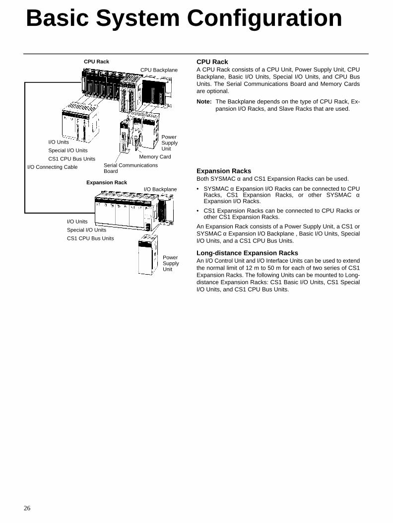
CPU RackA CPU Rack consists of a CPU Unit, Power Supply Unit, CPUBackplane, Basic I/O Units, Special I/O Units, and CPU BusUnits. The Serial Communications Board and Memory Cardsare optional.
Note: The Backplane depends on the type of CPU Rack, Ex-pansion I/O Racks, and Slave Racks that are used.
Expansion RacksBoth SYSMAC α and CS1 Expansion Racks can be used.
• SYSMAC α Expansion I/O Racks can be connected to CPURacks, CS1 Expansion Racks, or other SYSMAC αExpansion I/O Racks.
• CS1 Expansion Racks can be connected to CPU Racks orother CS1 Expansion Racks.
An Expansion Rack consists of a Power Supply Unit, a CS1 orSYSMAC α Expansion I/O Backplane , Basic I/O Units, SpecialI/O Units, and a CS1 CPU Bus Units.
Long-distance Expansion RacksAn I/O Control Unit and I/O Interface Units can be used to extendthe normal limit of 12 m to 50 m for each of two series of CS1Expansion Racks. The following Units can be mounted to Long-distance Expansion Racks: CS1 Basic I/O Units, CS1 SpecialI/O Units, and CS1 CPU Bus Units.
Basic System Configuration
27
ConfigurationName Configuration Remarks
CPU Rack CPU Backplane One of each Unit required for every CPU Rack.C U ac
CPU Unit
O e o eac U equ ed o e e y C U ac
Refer to the following table for model number.
Power Supply Unit
Refer to the following table for model number.
Memory Card Install as required.
Serial Communications Board
q
Refer to the following table for model number.
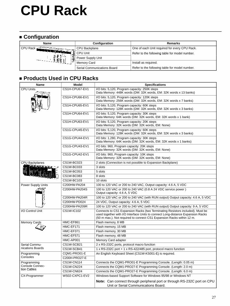
Products Used in CPU RacksName Model Specifications
CPU Units CS1H-CPU67-EV1 I/O bits: 5,120, Program capacity: 250K stepsData Memory: 448K words (DM: 32K words, EM: 32K words x 13 banks)
CS1H-CPU66-EV1 I/O bits: 5,120, Program capacity: 120K stepsData Memory: 256K words (DM: 32K words, EM: 32K words x 7 banks)
CS1H-CPU65-EV1 I/O bits: 5,120, Program capacity: 60K stepsData Memory: 128K words (DM: 32K words, EM: 32K words x 3 banks)
CS1H-CPU64-EV1 I/O bits: 5,120, Program capacity: 30K stepsData Memory: 64K words (DM: 32K words, EM: 32K words x 1 bank)
CS1H-CPU63-EV1 I/O bits: 5,120, Program capacity: 20K stepsData Memory: 32K words (DM: 32K words, EM: None)
CS1G-CPU45-EV1 I/O bits: 5,120, Program capacity: 60K stepsData Memory: 128K words (DM: 32K words, EM: 32K words x 3 banks)
CS1G-CPU44-EV1 I/O bits: 1,280, Program capacity: 30K stepsData Memory: 64K words (DM: 32K words, EM: 32K words x 1 banks)
CS1G-CPU43-EV1 I/O bits: 960, Program capacity: 20K stepsData Memory: 32K words (DM: 32K words, EM: None)
CS1G-CPU42-EV1 I/O bits: 960, Program capacity: 10K stepsData Memory: 32K words (DM: 32K words, EM: None)
CPU Backplanes CS1W-BC023 2 slots (Connection is not possible to Expansion Backplane)C U ac a esCS1W-BC033 3 slotsCS1W-BC053 5 slots
CS1W-BC083 8 slotsCS1W-BC103 10 slots
Power Supply Units C200HW-PA204 100 to 120 VAC or 200 to 240 VAC, Output capacity: 4.6 A, 5 VDCo e Su y U sC200HW-PA204S 100 to 120 VAC or 200 to 240 VAC (0.8 A 24 VDC service power )
Output capacity: 4.6 A, 5 VDC
C200HW-PA204R 100 to 120 VAC or 200 to 240 VAC (with RUN output) Output capacity: 4.6 A, 5 VDC
C200HW-PD024 24 VDC, Output capacity: 4.6 A, 5 VDCC200HW-PA209R 100 to 120 VAC or 200 to 240 VAC (with RUN output) Output capacity: 9 A, 5 VDC
I/O Control Unit CS1W-IC102 Connects to CS1 Expansion Racks (two Terminating Resistors included). Must beused together with I/O Interface Units to connect Long-distance Expansion Racks(50 m max.). Not required to connect CS1 Expansion Racks within 12 m.
Memory Cards HMC-EF861 Flash memory, 8 MBe o y Ca dsHMC-EF171 Flash memory, 15 MBHMC-EF371 Flash memory, 30 MBHMC-EF571 Flash memory, 48 MB
HMC-AP001 Memory Card adapter
Serial Commu-i ti B d
CS1W-SCB21 2 x RS-232C ports, protocol macro functionSe a Co unications Boards CS1W-SCB41 1 x RS-232C port + 1 x RS-422/485 port, protocol macro function
ProgrammingC l
CQM1-PRO01-E An English Keyboard Sheet (CS1W-KS001-E) is required.og a gConsoles C200H-PRO27-E
g s eyboa d S ee (CS S00 ) s equ ed
ProgrammingC l C
CS1W-CN114 Connects the CQM1-PRO01-E Programming Console. (Length: 0.05 m)og a gConsole Connec-tion Cables
CS1W-CN224 Connects the CQM1-PRO27-E Programming Console. (Length: 2.0 m)tion Cables
CS1W-CN624 Connects the CQM1-PRO27-E Programming Console. (Length: 6.0 m)
CX-Programmer WS02-CXPC1-EV2 Windows-based Support Software for Windows 95/98 or Windows NT
Note: Can connect through peripheral port or through RS-232C port on CPUUnit or Serial Communications Board.
CPU Rack
CPU Rack
28
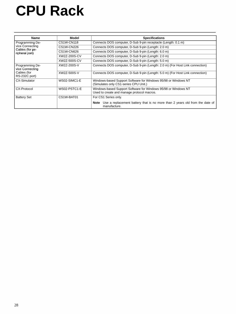
Name SpecificationsModelProgramming De-i C ti
CS1W-CN118 Connects DOS computer, D-Sub 9-pin receptacle (Length: 0.1 m)og a g evice ConnectingCables (for pe
CS1W-CN226 Connects DOS computer, D-Sub 9-pin (Length: 2.0 m)Cables (for pe-ripheral port) CS1W-CN626 Connects DOS computer, D-Sub 9-pin (Length: 6.0 m)ri heral ort)
XW2Z-200S-CV Connects DOS computer, D-Sub 9-pin (Length: 2.0 m)
XW2Z-500S-CV Connects DOS computer, D-Sub 9-pin (Length: 5.0 m)
Programming De-vice Connecting
XW2Z-200S-V Connects DOS computer, D-Sub 9-pin (Length: 2.0 m) (For Host Link connection)vice ConnectingCables (forRS-232C port)
XW2Z-500S-V Connects DOS computer, D-Sub 9-pin (Length: 5.0 m) (For Host Link connection)
CX-Simulator WS02-SIMC1-E Windows-based Support Software for Windows 95/98 or Windows NT (Simulates only CS1-series CPU Unit.)
CX-Protocol WS02-PSTC1-E Windows-based Support Software for Windows 95/98 or Windows NT Used to create and manage protocol macros.
Battery Set CS1W-BAT01 For CS1 Series only.
Note Use a replacement battery that is no more than 2 years old from the date ofmanufacture.
29
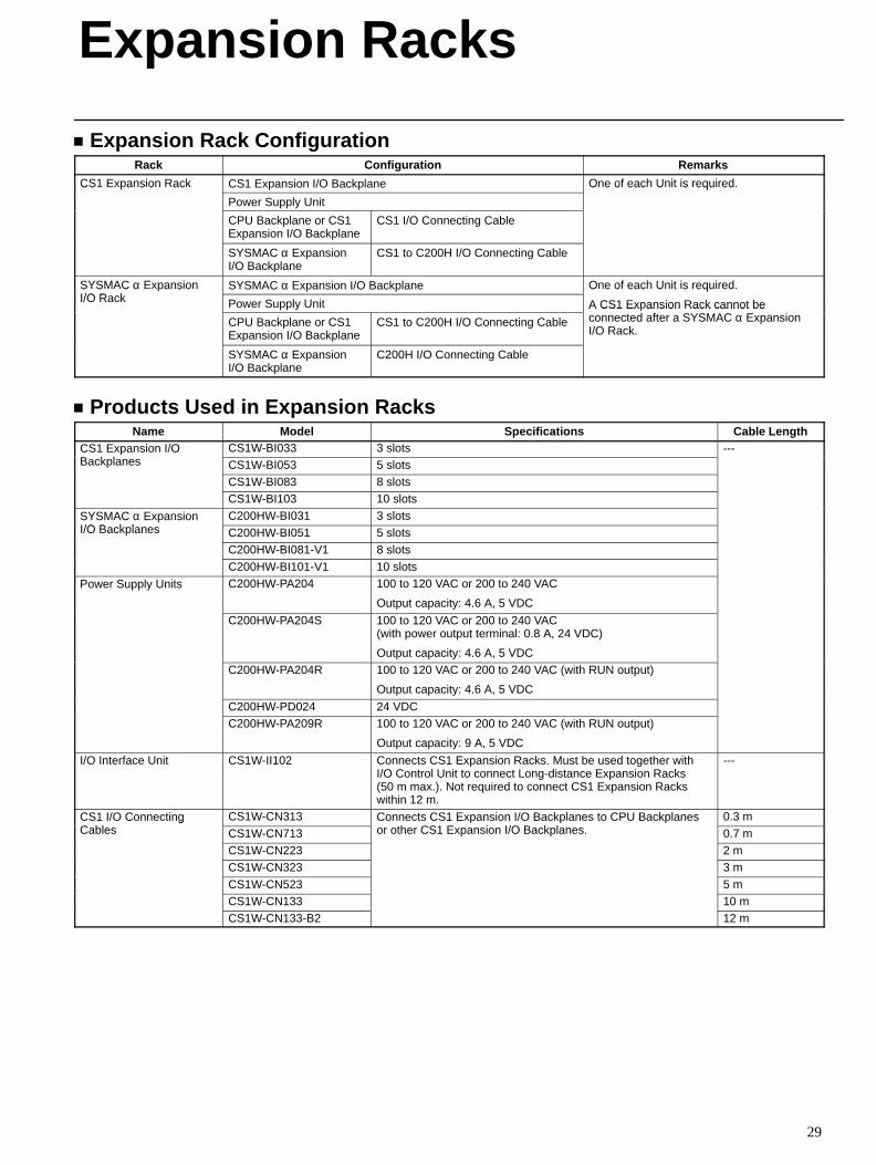
Expansion Rack ConfigurationRack Configuration Remarks
CS1 Expansion Rack CS1 Expansion I/O Backplane One of each Unit is required.CS a s o ac
Power Supply Unit
O e o eac U s equ ed
CPU Backplane or CS1Expansion I/O Backplane
CS1 I/O Connecting Cable
SYSMAC α ExpansionI/O Backplane
CS1 to C200H I/O Connecting Cable
SYSMAC α ExpansionI/O R k
SYSMAC α Expansion I/O Backplane One of each Unit is required.S S C α a s oI/O Rack Power Supply Unit
O e o eac U s equ ed
A CS1 Expansion Rack cannot be
CPU Backplane or CS1Expansion I/O Backplane
CS1 to C200H I/O Connecting Cable
A CS1 Ex ansion Rack cannot beconnected after a SYSMAC α ExpansionI/O Rack.
SYSMAC α ExpansionI/O Backplane
C200H I/O Connecting Cable
Products Used in Expansion RacksName Model Specifications Cable Length
CS1 Expansion I/OB k l
CS1W-BI033 3 slots ---CS a s o /OBackplanes CS1W-BI053 5 slots
CS1W-BI083 8 slotsCS1W-BI103 10 slots
SYSMAC α ExpansionI/O B k l
C200HW-BI031 3 slotsS S C α a s oI/O Backplanes C200HW-BI051 5 slots
C200HW-BI081-V1 8 slots
C200HW-BI101-V1 10 slots
Power Supply Units C200HW-PA204 100 to 120 VAC or 200 to 240 VAC
Output capacity: 4.6 A, 5 VDC
C200HW-PA204S 100 to 120 VAC or 200 to 240 VAC (with power output terminal: 0.8 A, 24 VDC)
Output capacity: 4.6 A, 5 VDCC200HW-PA204R 100 to 120 VAC or 200 to 240 VAC (with RUN output)
Output capacity: 4.6 A, 5 VDC
C200HW-PD024 24 VDCC200HW-PA209R 100 to 120 VAC or 200 to 240 VAC (with RUN output)
Output capacity: 9 A, 5 VDC
I/O Interface Unit CS1W-II102 Connects CS1 Expansion Racks. Must be used together withI/O Control Unit to connect Long-distance Expansion Racks(50 m max.). Not required to connect CS1 Expansion Rackswithin 12 m.
---
CS1 I/O ConnectingC bl
CS1W-CN313 Connects CS1 Expansion I/O Backplanes to CPU Backplanesth CS1 E i I/O B k l
0.3 mCS /O Co ec gCables CS1W-CN713
Co ec s CS a s o /O ac a es o C U ac a esor other CS1 Expansion I/O Backplanes. 0.7 m
CS1W-CN223 2 mCS1W-CN323 3 m
CS1W-CN523 5 mCS1W-CN133 10 mCS1W-CN133-B2 12 m
Expansion Racks
Expansion Racks
30
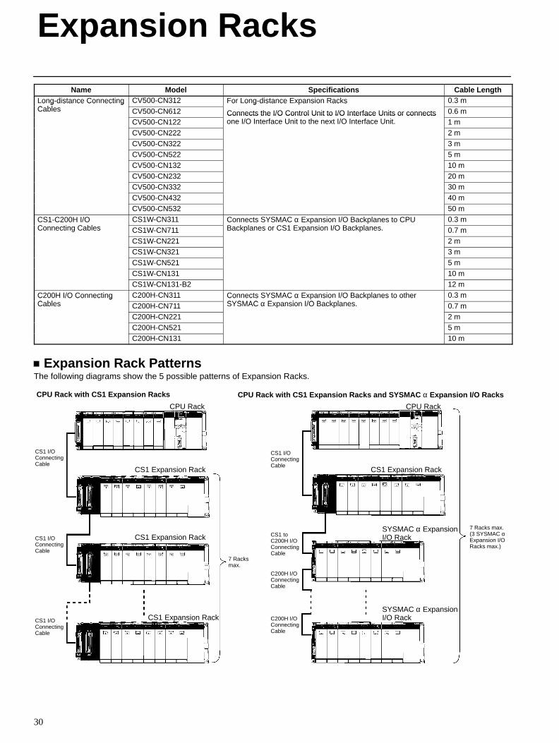
Name Cable LengthSpecificationsModelLong-distance ConnectingC bl
CV500-CN312 For Long-distance Expansion Racks 0.3 mo g d s a ce Co ec gCables CV500-CN612
o o g d s a ce a s o ac s
Connects the I/O Control Unit to I/O Interface Units or connects 0.6 mCV500-CN122
Connects the I/O Control Unit to I/O Interface Units or connectsone I/O Interface Unit to the next I/O Interface Unit. 1 m
CV500-CN222 2 m
CV500-CN322 3 mCV500-CN522 5 mCV500-CN132 10 m
CV500-CN232 20 mCV500-CN332 30 mCV500-CN432 40 m
CV500-CN532 50 m
CS1-C200H I/OC ti C bl
CS1W-CN311 Connects SYSMAC α Expansion I/O Backplanes to CPUB k l CS1 E i I/O B k l
0.3 mCS C 00 /OConnecting Cables CS1W-CN711
Co ec s S S C α a s o /O ac a es o C UBackplanes or CS1 Expansion I/O Backplanes. 0.7 m
CS1W-CN221 2 mCS1W-CN321 3 mCS1W-CN521 5 m
CS1W-CN131 10 mCS1W-CN131-B2 12 m
C200H I/O ConnectingC bl
C200H-CN311 Connects SYSMAC α Expansion I/O Backplanes to otherSYSMAC E i I/O B k l
0.3 mC 00 /O Co ec gCables C200H-CN711
Co ec s S S C α a s o /O ac a es o o eSYSMAC α Expansion I/O Backplanes. 0.7 m
C200H-CN221 2 mC200H-CN521 5 mC200H-CN131 10 m
Expansion Rack PatternsThe following diagrams show the 5 possible patterns of Expansion Racks.
CPU Rack with CS1 Expansion Racks
CPU Rack
CS1 I/OConnectingCable
CS1 I/OConnectingCable
CS1 Expansion Rack
7 Racksmax.
CS1 I/OConnectingCable
CS1 Expansion Rack
CS1 Expansion Rack
CPU Rack with CS1 Expansion Racks and SYSMAC α Expansion I/O Racks
7 Racks max.(3 SYSMAC αExpansion I/ORacks max.)
CS1 Expansion Rack
SYSMAC α ExpansionI/O RackCS1 to
C200H I/O ConnectingCable
CPU Rack
CS1 I/OConnectingCable
C200H I/OConnectingCable
C200H I/OConnectingCable
SYSMAC α ExpansionI/O Rack
Expansion Racks
31
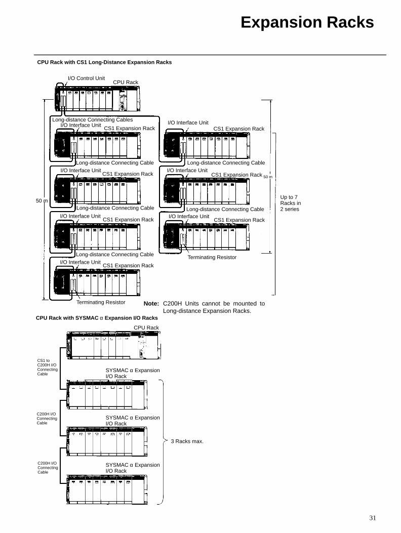
CPU Rack with CS1 Long-Distance Expansion Racks
CPU Rack
CS1 Expansion Rack
CS1 Expansion Rack
CS1 Expansion Rack
CS1 Expansion Rack
Note: C200H Units cannot be mounted toLong-distance Expansion Racks.
CS1 Expansion Rack
CS1 Expansion Rack
CS1 Expansion Rack
50 m
50 m
I/O Control Unit
I/O Interface Unit
I/O Interface Unit
I/O Interface Unit
I/O Interface Unit
I/O Interface Unit
I/O Interface Unit
I/O Interface Unit
Terminating Resistor
Terminating Resistor
Long-distance Connecting Cables
Long-distance Connecting Cable
Long-distance Connecting Cable
Long-distance Connecting Cable
Long-distance Connecting Cable
Long-distance Connecting Cable
Up to 7Racks in2 series
CPU Rack with SYSMAC α Expansion I/O Racks
CPU Rack
CS1 toC200H I/OConnectingCable
C200H I/OConnectingCable
C200H I/OConnectingCable
SYSMAC α ExpansionI/O Rack
3 Racks max.
SYSMAC α ExpansionI/O Rack
SYSMAC α ExpansionI/O Rack
Expansion Racks
32
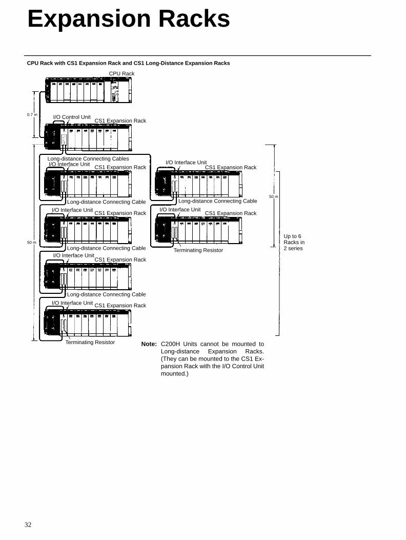
CPU Rack with CS1 Expansion Rack and CS1 Long-Distance Expansion Racks
CPU Rack
CS1 Expansion Rack
CS1 Expansion Rack
CS1 Expansion Rack
CS1 Expansion Rack
Note:
CS1 Expansion Rack
CS1 Expansion Rack
CS1 Expansion Rack
0.7 m
50 m
50 m
Note: C200H Units cannot be mounted toLong-distance Expansion Racks.(They can be mounted to the CS1 Ex-pansion Rack with the I/O Control Unitmounted.)
I/O Control Unit
I/O Interface Unit
Terminating Resistor
Long-distance Connecting Cables
Up to 6Racks in2 seriesTerminating Resistor
I/O Interface Unit
I/O Interface Unit
I/O Interface Unit
I/O Interface Unit
I/O Interface UnitLong-distance Connecting Cable
Long-distance Connecting Cable
Long-distance Connecting Cable
Long-distance Connecting Cable
33
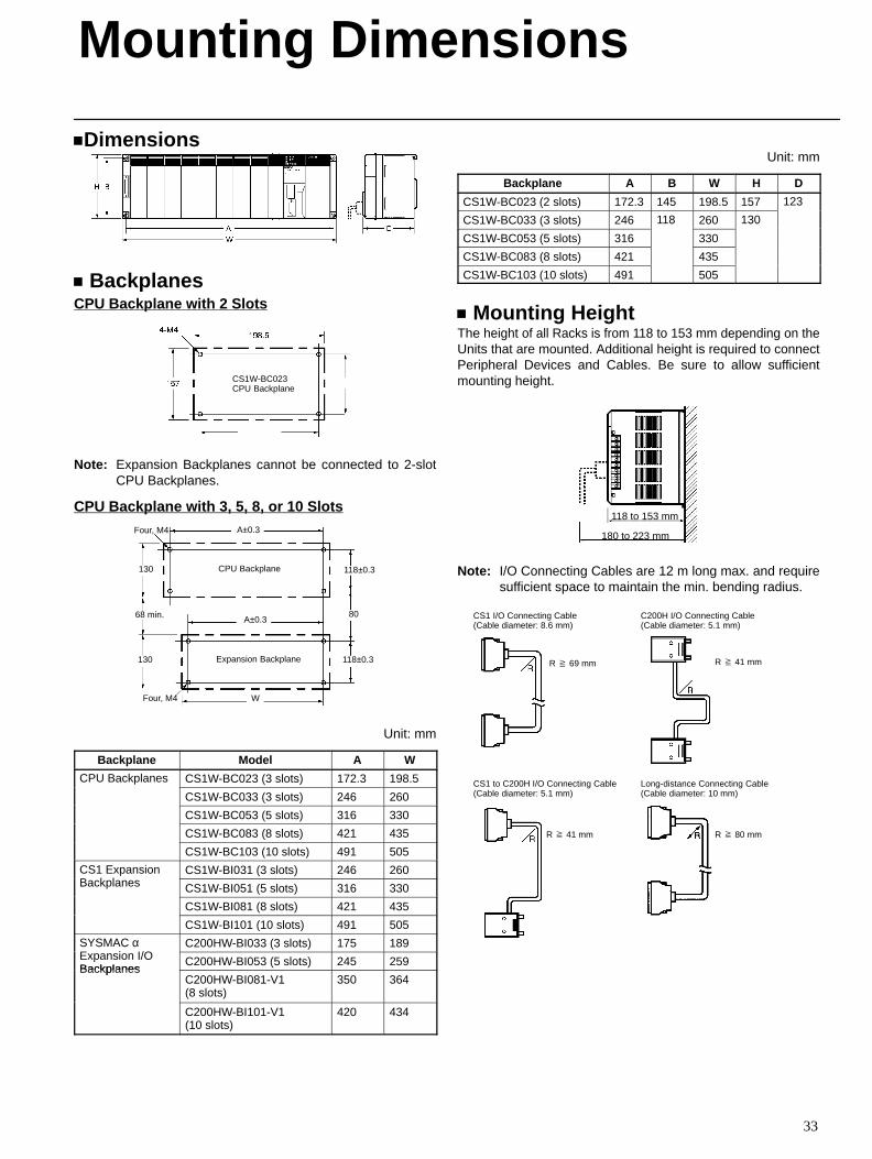
Dimensions
BackplanesCPU Backplane with 2 Slots
CS1W-BC023CPU Backplane
Note: Expansion Backplanes cannot be connected to 2-slotCPU Backplanes.
CPU Backplane with 3, 5, 8, or 10 SlotsA±0.3
118±0.3
80
118±0.3
WFour, M4
130
68 min.
130 CPU Backplane
Expansion Backplane
Four, M4
A±0.3
Unit: mm
Backplane Model A W
CPU Backplanes CS1W-BC023 (3 slots) 172.3 198.5C U ac a es
CS1W-BC033 (3 slots) 246 260
CS1W-BC053 (5 slots) 316 330
CS1W-BC083 (8 slots) 421 435
CS1W-BC103 (10 slots) 491 505
CS1 ExpansionB k l
CS1W-BI031 (3 slots) 246 260CS a s oBackplanes CS1W-BI051 (5 slots) 316 330
CS1W-BI081 (8 slots) 421 435
CS1W-BI101 (10 slots) 491 505
SYSMAC α E i I/O
C200HW-BI033 (3 slots) 175 189S S C αExpansion I/OBackplanes
C200HW-BI053 (5 slots) 245 259Backplanes
C200HW-BI081-V1 (8 slots)
350 364
C200HW-BI101-V1 (10 slots)
420 434
Unit: mm
Backplane A B W H D
CS1W-BC023 (2 slots) 172.3 145 198.5 157 123
CS1W-BC033 (3 slots) 246 118 260 130
3
CS1W-BC053 (5 slots) 316
8
330
30
CS1W-BC083 (8 slots) 421 435
CS1W-BC103 (10 slots) 491 505
Mounting HeightThe height of all Racks is from 118 to 153 mm depending on theUnits that are mounted. Additional height is required to connectPeripheral Devices and Cables. Be sure to allow sufficientmounting height.
118 to 153 mm
180 to 223 mm
Note: I/O Connecting Cables are 12 m long max. and requiresufficient space to maintain the min. bending radius.
CS1 I/O Connecting Cable(Cable diameter: 8.6 mm)
CS1 to C200H I/O Connecting Cable(Cable diameter: 5.1 mm)
C200H I/O Connecting Cable(Cable diameter: 5.1 mm)
R 69 mm R 41 mm
R 41 mm
Long-distance Connecting Cable(Cable diameter: 10 mm)
R 80 mm
Mounting Dimensions
34
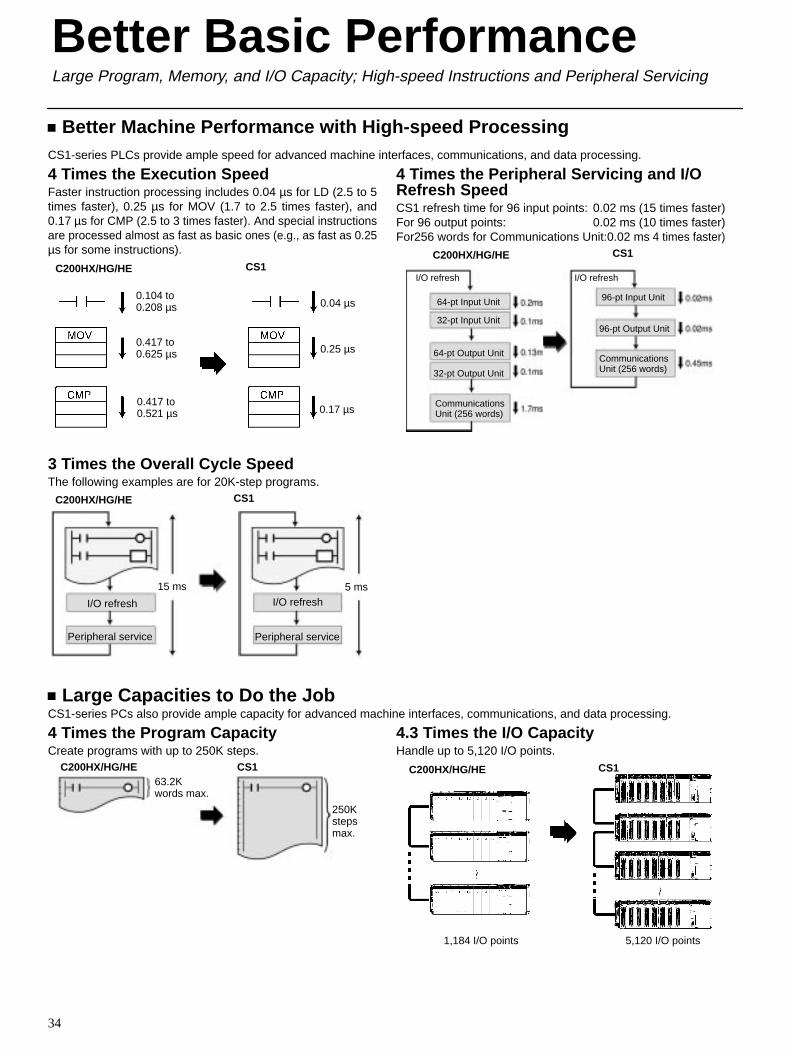
Better Machine Performance with High-speed ProcessingCS1-series PLCs provide ample speed for advanced machine interfaces, communications, and data processing.
4 Times the Execution SpeedFaster instruction processing includes 0.04 µs for LD (2.5 to 5times faster), 0.25 µs for MOV (1.7 to 2.5 times faster), and0.17 µs for CMP (2.5 to 3 times faster). And special instructionsare processed almost as fast as basic ones (e.g., as fast as 0.25µs for some instructions).
C200HX/HG/HE CS1
0.104 to0.208 µs
0.417 to0.625 µs
0.417 to0.521 µs
0.04 µs
0.25 µs
0.17 µs
3 Times the Overall Cycle SpeedThe following examples are for 20K-step programs.
C200HX/HG/HE CS1
I/O refresh
Peripheral service
I/O refresh
Peripheral service
15 ms 5 ms
4 Times the Peripheral Servicing and I/ORefresh SpeedCS1 refresh time for 96 input points: 0.02 ms (15 times faster)For 96 output points: 0.02 ms (10 times faster)For256 words for Communications Unit:0.02 ms 4 times faster)
C200HX/HG/HE CS1
I/O refresh
64-pt Input Unit
64-pt Output Unit
CommunicationsUnit (256 words)
32-pt Output Unit
32-pt Input Unit
96-pt Input Unit
CommunicationsUnit (256 words)
96-pt Output Unit
I/O refresh
Large Capacities to Do the JobCS1-series PCs also provide ample capacity for advanced machine interfaces, communications, and data processing.
4 Times the Program CapacityCreate programs with up to 250K steps.
C200HX/HG/HE CS163.2Kwords max.
250Kstepsmax.
4.3 Times the I/O CapacityHandle up to 5,120 I/O points.
C200HX/HG/HE CS1
1,184 I/O points 5,120 I/O points
Better Basic PerformanceLarge Program, Memory, and I/O Capacity; High-speed Instructions and Peripheral Servicing
Better Basic Performance
35
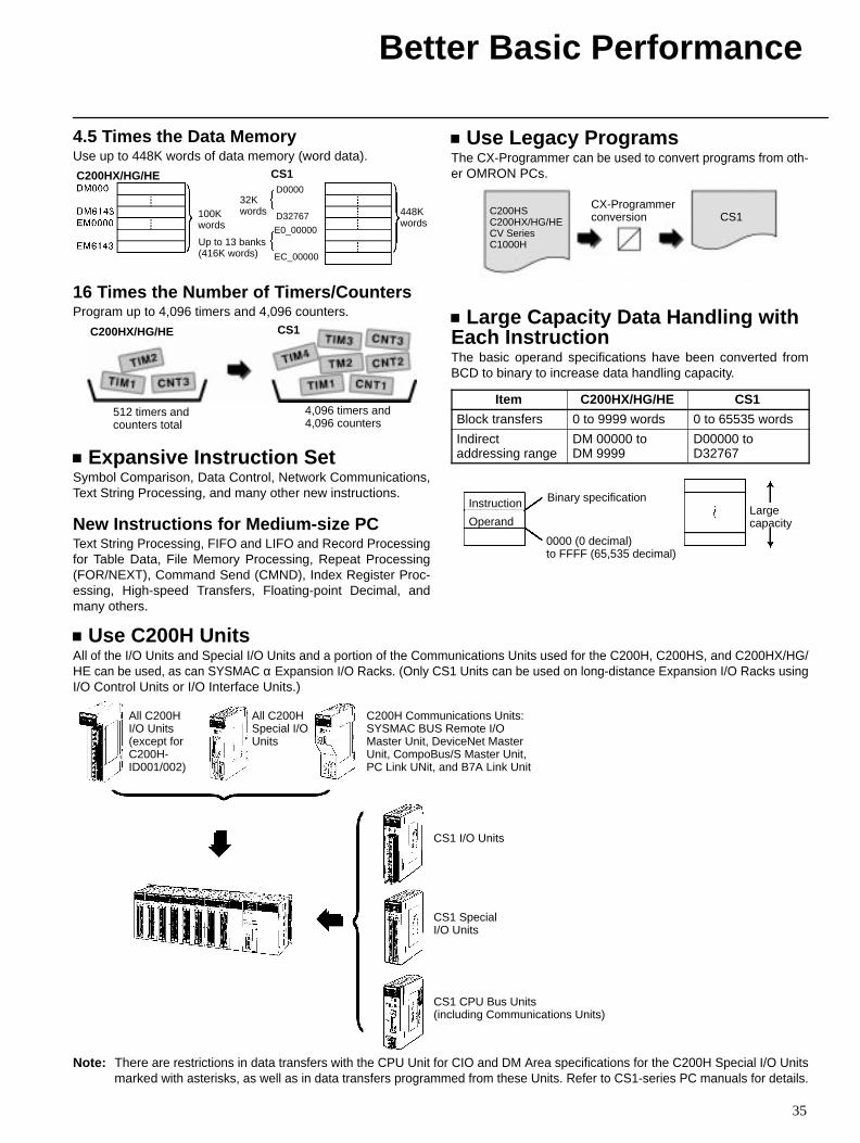
4.5 Times the Data MemoryUse up to 448K words of data memory (word data).
C200HX/HG/HE CS1
100K words
32Kwords
Up to 13 banks(416K words)
448Kwords
D0000
D32767
E0_00000
EC_00000
16 Times the Number of Timers/CountersProgram up to 4,096 timers and 4,096 counters.
C200HX/HG/HE CS1
512 timers andcounters total
4,096 timers and4,096 counters
Expansive Instruction SetSymbol Comparison, Data Control, Network Communications,Text String Processing, and many other new instructions.
New Instructions for Medium-size PCText String Processing, FIFO and LIFO and Record Processingfor Table Data, File Memory Processing, Repeat Processing(FOR/NEXT), Command Send (CMND), Index Register Proc-essing, High-speed Transfers, Floating-point Decimal, andmany others.
Use Legacy ProgramsThe CX-Programmer can be used to convert programs from oth-er OMRON PCs.
CX-Programmerconversion CS1C200HS
C200HX/HG/HECV SeriesC1000H
Large Capacity Data Handling withEach InstructionThe basic operand specifications have been converted fromBCD to binary to increase data handling capacity.
Item C200HX/HG/HE CS1
Block transfers 0 to 9999 words 0 to 65535 words
Indirectaddressing range
DM 00000 toDM 9999
D00000 toD32767
Instruction
Operand
Binary specification
0000 (0 decimal) to FFFF (65,535 decimal)
Largecapacity
Use C200H UnitsAll of the I/O Units and Special I/O Units and a portion of the Communications Units used for the C200H, C200HS, and C200HX/HG/HE can be used, as can SYSMAC α Expansion I/O Racks. (Only CS1 Units can be used on long-distance Expansion I/O Racks usingI/O Control Units or I/O Interface Units.)
All C200HI/O Units(except forC200H-ID001/002)
All C200HSpecial I/OUnits
C200H Communications Units: SYSMAC BUS Remote I/OMaster Unit, DeviceNet MasterUnit, CompoBus/S Master Unit,PC Link UNit, and B7A Link Unit
CS1 I/O Units
CS1 SpecialI/O Units
CS1 CPU Bus Units (including Communications Units)
Note: There are restrictions in data transfers with the CPU Unit for CIO and DM Area specifications for the C200H Special I/O Unitsmarked with asterisks, as well as in data transfers programmed from these Units. Refer to CS1-series PC manuals for details.
36
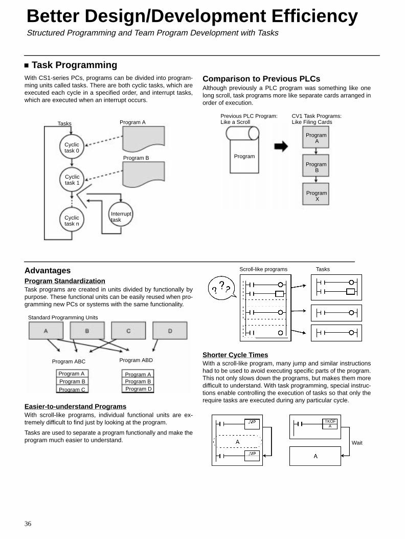
Task ProgrammingWith CS1-series PCs, programs can be divided into program-ming units called tasks. There are both cyclic tasks, which areexecuted each cycle in a specified order, and interrupt tasks,which are executed when an interrupt occurs.
Tasks Program A
Program B
Cyclictask 0
Cyclictask n
Cyclictask 1
Interrupttask
Comparison to Previous PLCsAlthough previously a PLC program was something like onelong scroll, task programs more like separate cards arranged inorder of execution.
Previous PLC Program:Like a Scroll
CV1 Task Programs:Like Filing Cards
Program
Program A
Program B
Program X
AdvantagesProgram StandardizationTask programs are created in units divided by functionally bypurpose. These functional units can be easily reused when pro-gramming new PCs or systems with the same functionality.
Standard Programming Units
Program ABC
Program AProgram B
Program C
Program ABD
Program AProgram BProgram D
Easier-to-understand ProgramsWith scroll-like programs, individual functional units are ex-tremely difficult to find just by looking at the program.
Tasks are used to separate a program functionally and make theprogram much easier to understand.
Scroll-like programs Tasks
Shorter Cycle TimesWith a scroll-like program, many jump and similar instructionshad to be used to avoid executing specific parts of the program.This not only slows down the programs, but makes them moredifficult to understand. With task programming, special instruc-tions enable controlling the execution of tasks so that only therequire tasks are executed during any particular cycle.
Wait
TKOFA
Better Design/Development EfficiencyStructured Programming and Team Program Development with Tasks
Better Design/Development Efficiency
37
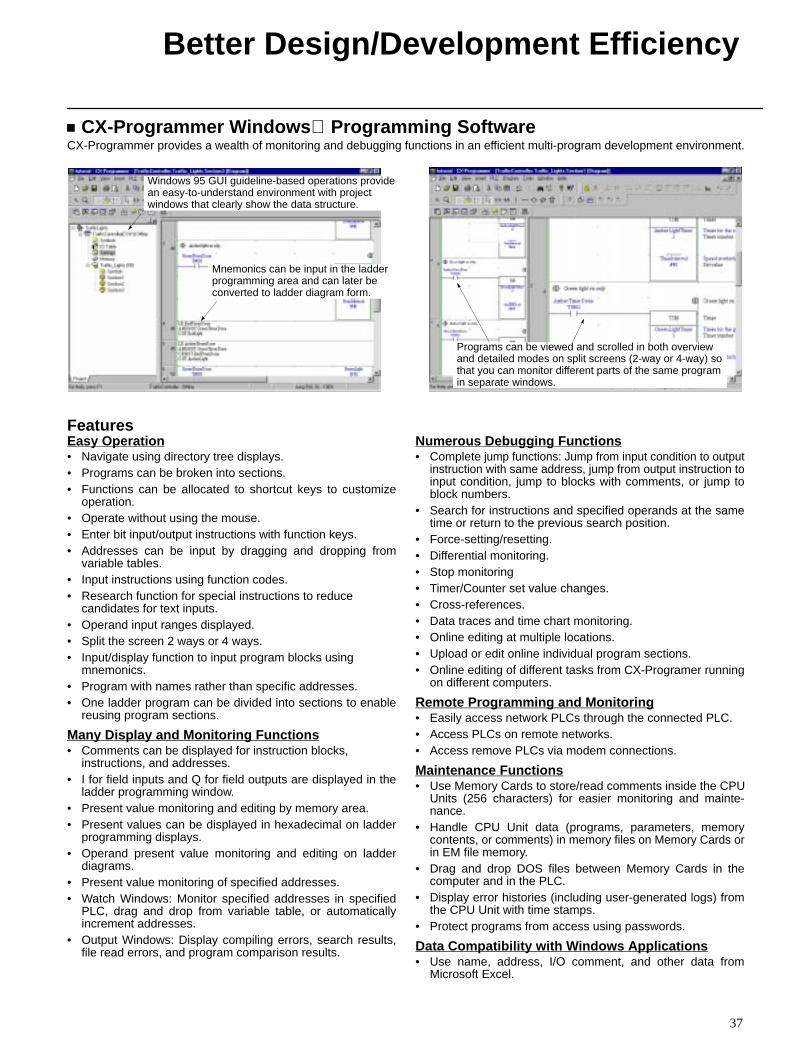
CX-Programmer Windows Programming SoftwareCX-Programmer provides a wealth of monitoring and debugging functions in an efficient multi-program development environment.
Windows 95 GUI guideline-based operations provide an easy-to-understand environment with project windows that clearly show the data structure.
Mnemonics can be input in the ladderprogramming area and can later beconverted to ladder diagram form.
Programs can be viewed and scrolled in both overviewand detailed modes on split screens (2-way or 4-way) sothat you can monitor different parts of the same programin separate windows.
FeaturesEasy Operation• Navigate using directory tree displays.• Programs can be broken into sections.• Functions can be allocated to shortcut keys to customize
operation.• Operate without using the mouse.• Enter bit input/output instructions with function keys.• Addresses can be input by dragging and dropping from
variable tables.• Input instructions using function codes.• Research function for special instructions to reduce
candidates for text inputs.• Operand input ranges displayed.• Split the screen 2 ways or 4 ways.• Input/display function to input program blocks using
mnemonics.• Program with names rather than specific addresses.• One ladder program can be divided into sections to enable
reusing program sections.
Many Display and Monitoring Functions• Comments can be displayed for instruction blocks,
instructions, and addresses.• I for field inputs and Q for field outputs are displayed in the
ladder programming window.• Present value monitoring and editing by memory area.• Present values can be displayed in hexadecimal on ladder
programming displays.• Operand present value monitoring and editing on ladder
diagrams.• Present value monitoring of specified addresses.• Watch Windows: Monitor specified addresses in specified
PLC, drag and drop from variable table, or automaticallyincrement addresses.
• Output Windows: Display compiling errors, search results,file read errors, and program comparison results.
Numerous Debugging Functions• Complete jump functions: Jump from input condition to output
instruction with same address, jump from output instruction toinput condition, jump to blocks with comments, or jump toblock numbers.
• Search for instructions and specified operands at the sametime or return to the previous search position.
• Force-setting/resetting.• Differential monitoring.• Stop monitoring• Timer/Counter set value changes.• Cross-references.• Data traces and time chart monitoring.• Online editing at multiple locations.• Upload or edit online individual program sections.• Online editing of different tasks from CX-Programer running
on different computers.
Remote Programming and Monitoring• Easily access network PLCs through the connected PLC.• Access PLCs on remote networks.• Access remove PLCs via modem connections.
Maintenance Functions• Use Memory Cards to store/read comments inside the CPU
Units (256 characters) for easier monitoring and mainte-nance.
• Handle CPU Unit data (programs, parameters, memorycontents, or comments) in memory files on Memory Cards orin EM file memory.
• Drag and drop DOS files between Memory Cards in thecomputer and in the PLC.
• Display error histories (including user-generated logs) fromthe CPU Unit with time stamps.
• Protect programs from access using passwords.
Data Compatibility with Windows Applications• Use name, address, I/O comment, and other data from
Microsoft Excel.
38
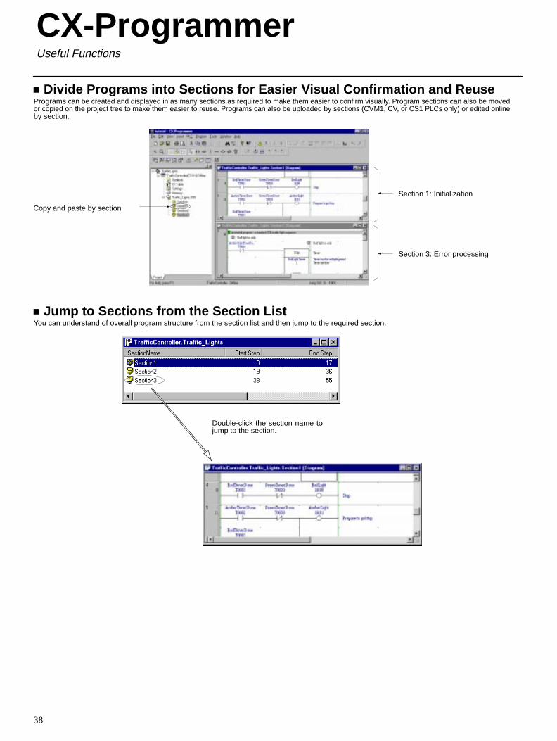
Divide Programs into Sections for Easier Visual Confirmation and ReusePrograms can be created and displayed in as many sections as required to make them easier to confirm visually. Program sections can also be movedor copied on the project tree to make them easier to reuse. Programs can also be uploaded by sections (CVM1, CV, or CS1 PLCs only) or edited onlineby section.
Section 1: Initialization
Section 3: Error processing
Copy and paste by section
Jump to Sections from the Section ListYou can understand of overall program structure from the section list and then jump to the required section.
Double-click the section name tojump to the section.
CX-ProgrammerUseful Functions
CX-Programmer
39
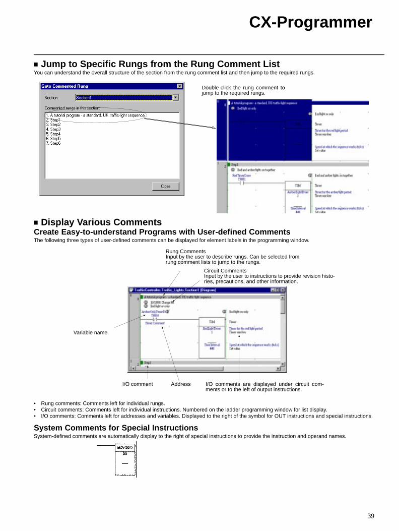
Jump to Specific Rungs from the Rung Comment ListYou can understand the overall structure of the section from the rung comment list and then jump to the required rungs.
Double-click the rung comment tojump to the required rungs.
Display Various CommentsCreate Easy-to-understand Programs with User-defined CommentsThe following three types of user-defined comments can be displayed for element labels in the programming window.
Rung CommentsInput by the user to describe rungs. Can be selected fromrung comment lists to jump to the rungs.
Circuit CommentsInput by the user to instructions to provide revision histo-ries, precautions, and other information.
Variable name
AddressI/O comment I/O comments are displayed under circuit com-ments or to the left of output instructions.
• Rung comments: Comments left for individual rungs.• Circuit comments: Comments left for individual instructions. Numbered on the ladder programming window for list display.• I/O comments: Comments left for addresses and variables. Displayed to the right of the symbol for OUT instructions and special instructions.
System Comments for Special InstructionsSystem-defined comments are automatically display to the right of special instructions to provide the instruction and operand names.
CX-Programmer
40
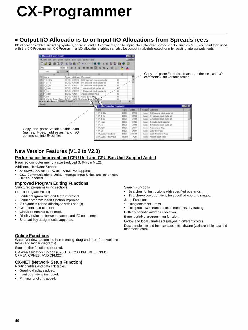
Output I/O Allocations to or Input I/O Allocations from SpreadsheetsI/O allocations tables, including symbols, address, and I/O comments,can be input into a standard spreadsheets, such as MS-Excel, and then usedwith the CX-Programmer. CX-Programmer I/O allocations tables can also be output in tab-delineated form for pasting into spreadsheets.
Copy and paste Excel data (names, addresses, and I/Ocomments) into variable tables.
Copy and paste variable table data(names, types, addresses, and I/Ocomments) into Excel files.
New Version Features (V1.2 to V2.0)Performance Improved and CPU Unit and CPU Bus Unit Support AddedRequired computer memory size (reduced 30% from V1.2).Additional Hardware Support• SYSMAC ISA Board PC and SRM1-V2 supported.• CS1 Communications Units, Interrupt Input Units, and other new
Units supported.
Improved Program Editing FunctionsStructured programs using sections.Ladder Program Editing• Ladder diagram size and fonts improved.• Ladder program insert function improved.• I/O symbols added (displayed with I and Q).• Comment load function.• Circuit comments supported.• Display switches between names and I/O comments.• Shortcut key assignments supported.
Search Functions• Searches for instructions with specified operands.• Search/replace operations for specified operand ranges.Jump Functions• Rung comment jumps.• Reciprocal I/O searches and search history tracing.Better automatic address allocation.Better variable programming function.Global and local variables displayed in different colors.Data transfers to and from spreadsheet software (variable table data andmnemonic data).
Online FunctionsWatch Window (automatic incrementing, drag and drop from variabletables and ladder diagrams).Stop monitor function supported.UM area allocation function (C200HS, C200HX/HG/HE, CPM1,CPM1A, CPM2B, AND CPM2C).
CX-NET (Network Setup Function)Routing tables and data link tables• Graphic displays added.• Input operations improved.• Printing functions added.
CX-Programmer
41
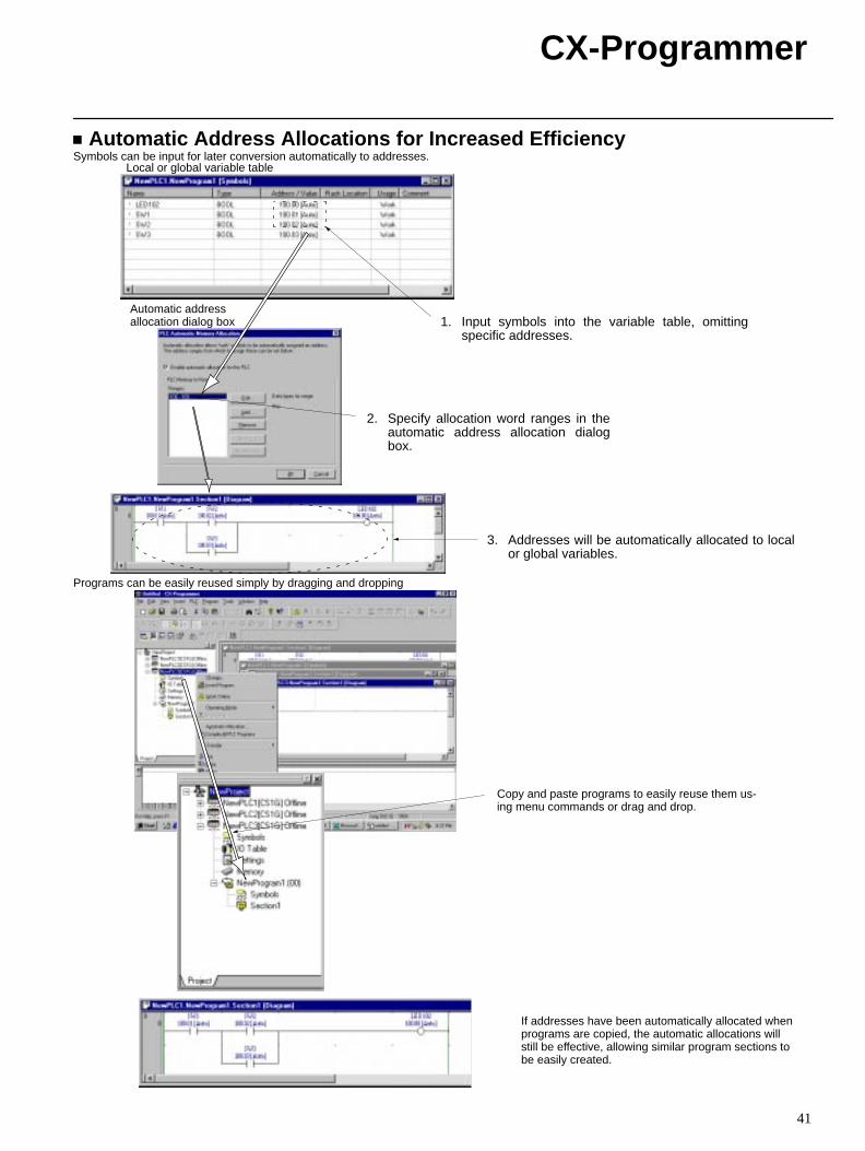
Automatic Address Allocations for Increased EfficiencySymbols can be input for later conversion automatically to addresses.
1. Input symbols into the variable table, omittingspecific addresses.
2. Specify allocation word ranges in theautomatic address allocation dialogbox.
3. Addresses will be automatically allocated to localor global variables.
Local or global variable table
Automatic address allocation dialog box
Programs can be easily reused simply by dragging and dropping
Copy and paste programs to easily reuse them us-ing menu commands or drag and drop.
If addresses have been automatically allocated whenprograms are copied, the automatic allocations willstill be effective, allowing similar program sections tobe easily created.
CX-Programmer
42
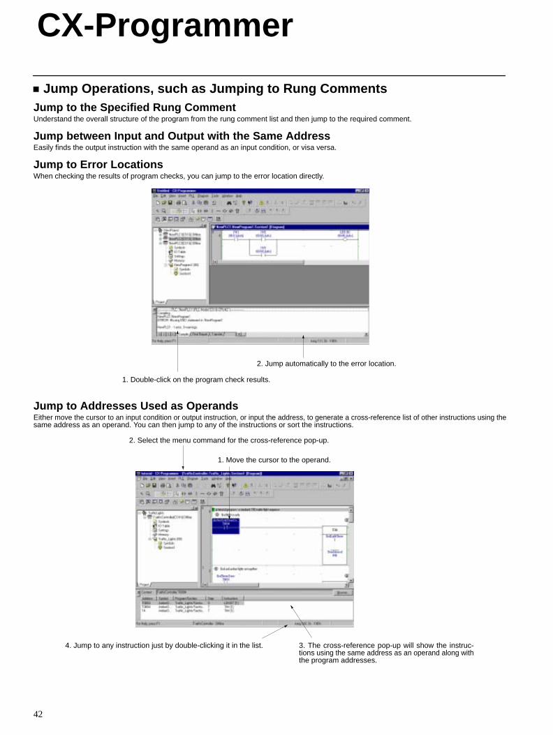
Jump Operations, such as Jumping to Rung CommentsJump to the Specified Rung CommentUnderstand the overall structure of the program from the rung comment list and then jump to the required comment.
Jump between Input and Output with the Same AddressEasily finds the output instruction with the same operand as an input condition, or visa versa.
Jump to Error LocationsWhen checking the results of program checks, you can jump to the error location directly.
2. Jump automatically to the error location.
1. Double-click on the program check results.
Jump to Addresses Used as OperandsEither move the cursor to an input condition or output instruction, or input the address, to generate a cross-reference list of other instructions using thesame address as an operand. You can then jump to any of the instructions or sort the instructions.
1. Move the cursor to the operand.
2. Select the menu command for the cross-reference pop-up.
4. Jump to any instruction just by double-clicking it in the list. 3. The cross-reference pop-up will show the instruc-tions using the same address as an operand along withthe program addresses.
CX-Programmer
43
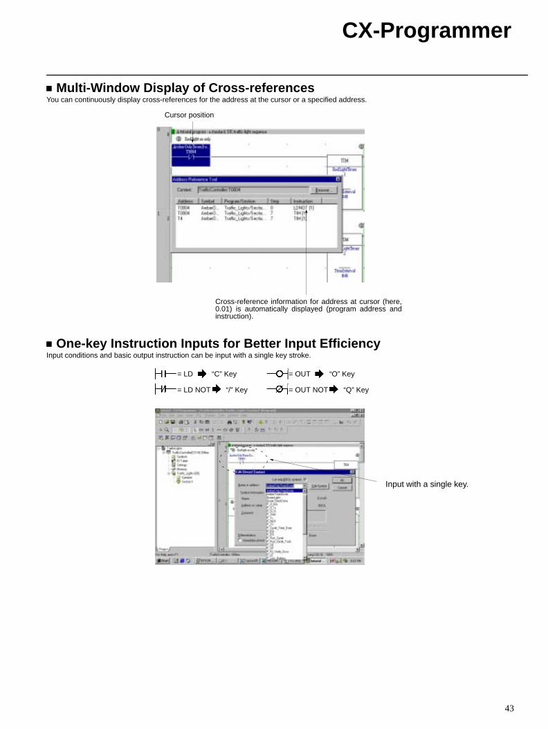
Multi-Window Display of Cross-referencesYou can continuously display cross-references for the address at the cursor or a specified address.
Cursor position
Cross-reference information for address at cursor (here,0.01) is automatically displayed (program address andinstruction).
One-key Instruction Inputs for Better Input EfficiencyInput conditions and basic output instruction can be input with a single key stroke.
Input with a single key.
= LD “C” Key
= LD NOT “/” Key
= OUT “O” Key
= OUT NOT “Q” Key
CX-Programmer
44
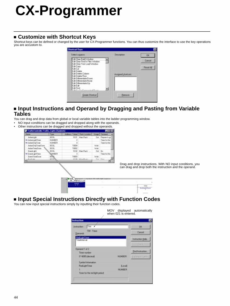
Customize with Shortcut KeysShortcut keys can be defined or changed by the user for CX-Programmer functions. You can thus customize the interface to use the key operationsyou are accustom to.
Input Instructions and Operand by Dragging and Pasting from VariableTablesYou can drag and drop data from global or local variable tables into the ladder programming window.• NO input conditions can be dragged and dropped along with the operands.• Other instructions can be dragged and dropped without the operands.
Drag and drop instructions. With NO input conditions, youcan drag and drop both the instruction and the operand.
Input Special Instructions Directly with Function CodesYou can now input special instructions simply by inputting their function codes.
MOV displayed automaticallywhen 021 is entered.
CX-Programmer
45
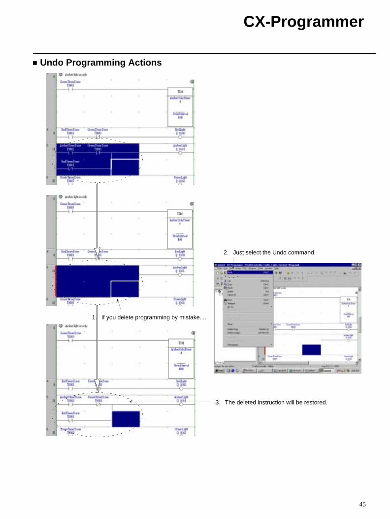
Undo Programming Actions
1. If you delete programming by mistake....
2. Just select the Undo command.
3. The deleted instruction will be restored.
CX-Programmer
46
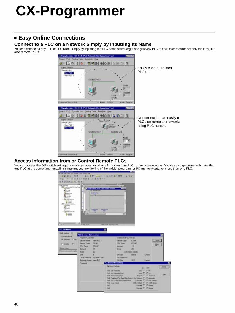
Easy Online ConnectionsConnect to a PLC on a Network Simply by Inputting Its NameYou can connect to any PLC on a network simply by inputting the PLC name of the target and gateway PLC to access or monitor not only the local, butalso remote PLCs.
Easily connect to localPLCs...
Or connect just as easily toPLCs on complex networksusing PLC names.
Access Information from or Control Remote PLCsYou can access the DIP switch settings, operating modes, or other information from PLCs on remote networks. You can also go online with more thanone PLC at the same time, enabling simultaneous monitoring of the ladder programs or I/O memory data for more than one PLC.
CX-Programmer
47
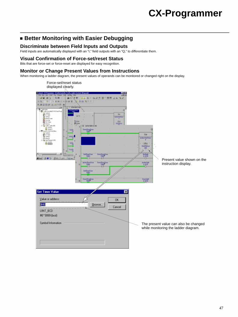
Better Monitoring with Easier DebuggingDiscriminate between Field Inputs and OutputsField inputs are automatically displayed with an “I,” field outputs with an “Q,” to differentiate them.
Visual Confirmation of Force-set/reset StatusBits that are force-set or force-reset are displayed for easy recognition.
Monitor or Change Present Values from InstructionsWhen monitoring a ladder diagram, the present values of operands can be monitored or changed right on the display.
Force-set/reset statusdisplayed clearly.
Present value shown on theinstruction display.
The present value can also be changedwhile monitoring the ladder diagram.
CX-Programmer
48
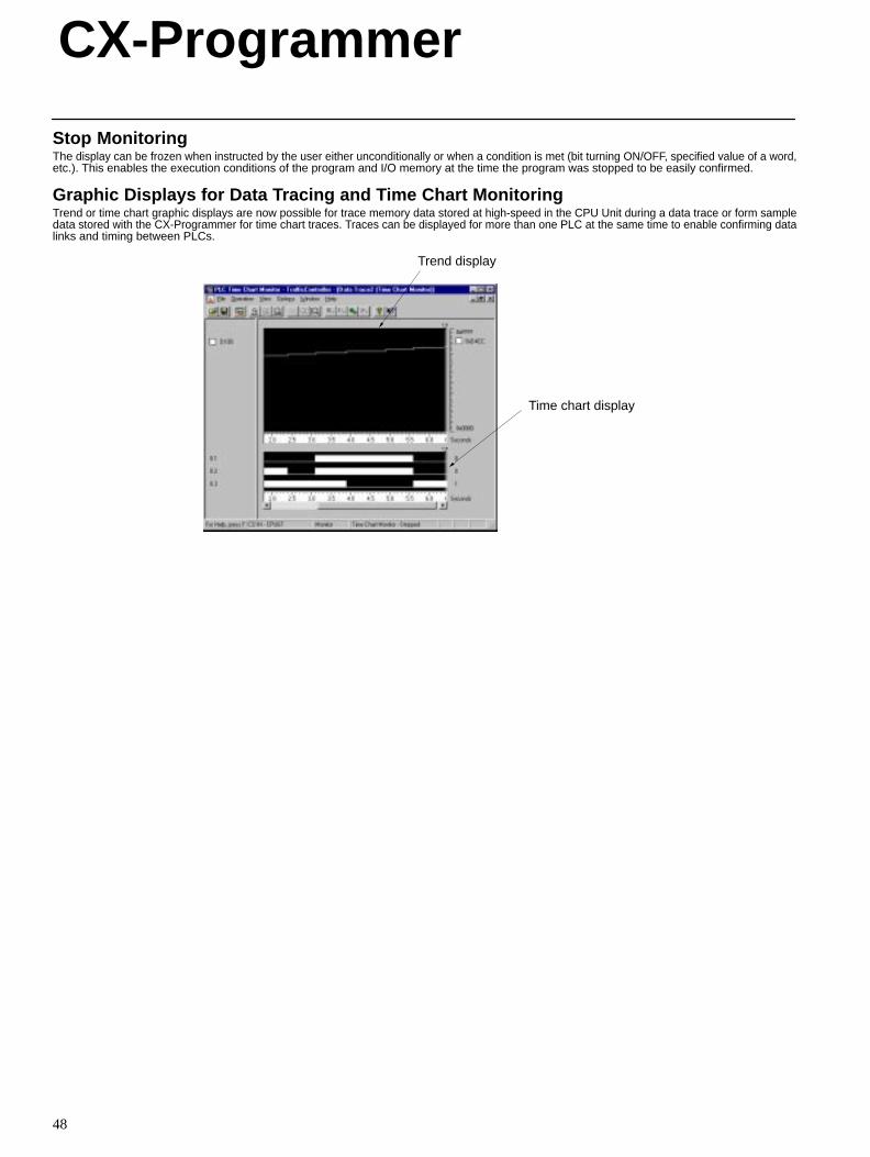
Stop MonitoringThe display can be frozen when instructed by the user either unconditionally or when a condition is met (bit turning ON/OFF, specified value of a word,etc.). This enables the execution conditions of the program and I/O memory at the time the program was stopped to be easily confirmed.
Graphic Displays for Data Tracing and Time Chart MonitoringTrend or time chart graphic displays are now possible for trace memory data stored at high-speed in the CPU Unit during a data trace or form sampledata stored with the CX-Programmer for time chart traces. Traces can be displayed for more than one PLC at the same time to enable confirming datalinks and timing between PLCs.
Trend display
Time chart display
CX-Simulator
49
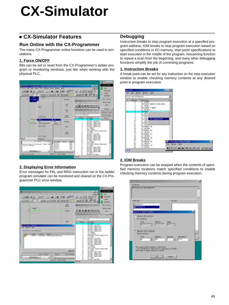
CX-Simulator FeaturesRun Online with the CX-ProgrammerThe many CX-Programmer online functions can be used in sim-ulations.
1. Force ON/OFFBits can be set or reset from the CX-Programmer’s ladder pro-gram or monitoring windows, just like when working with thephysical PLC.
2. Displaying Error InformationError messages for FAL and MSG instruction run in the ladderprogram simulator can be monitored and cleared on the CX-Pro-grammer PLC error window.
DebuggingInstruction breaks to stop program execution at a specified pro-gram address, IOM breaks to stop program execution based onspecified conditions in I/O memory, start point specifications tostart execution in the middle of the program, rescanning functionto repeat a scan from the beginning, and many other debuggingfunctions simplify the job of correcting programs.
1. Instruction BreaksA break point can be set for any instruction on the step executionwindow to enable checking memory contents at any desiredpoint in program execution.
2. IOM BreaksProgram execution can be stopped when the contents of speci-fied memory locations match specified conditions to enablechecking memory contents during program execution.
CX-Simulator
50
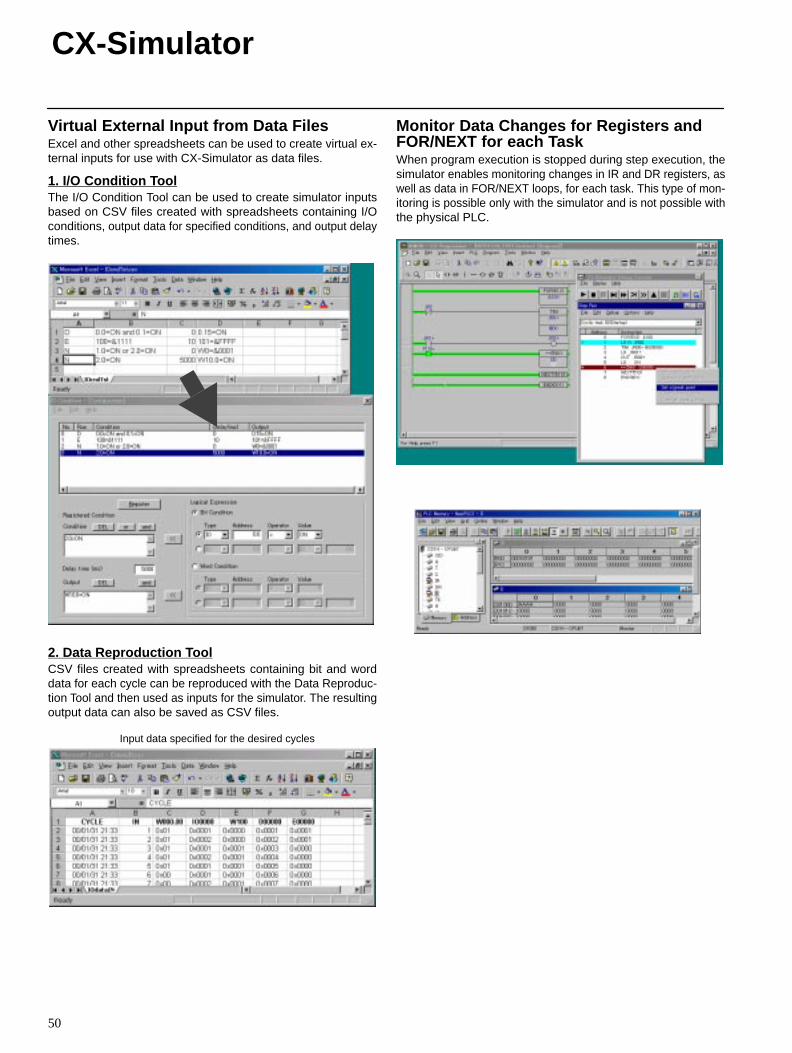
Virtual External Input from Data FilesExcel and other spreadsheets can be used to create virtual ex-ternal inputs for use with CX-Simulator as data files.
1. I/O Condition ToolThe I/O Condition Tool can be used to create simulator inputsbased on CSV files created with spreadsheets containing I/Oconditions, output data for specified conditions, and output delaytimes.
2. Data Reproduction ToolCSV files created with spreadsheets containing bit and worddata for each cycle can be reproduced with the Data Reproduc-tion Tool and then used as inputs for the simulator. The resultingoutput data can also be saved as CSV files.
Input data specified for the desired cycles
Monitor Data Changes for Registers andFOR/NEXT for each TaskWhen program execution is stopped during step execution, thesimulator enables monitoring changes in IR and DR registers, aswell as data in FOR/NEXT loops, for each task. This type of mon-itoring is possible only with the simulator and is not possible withthe physical PLC.
51
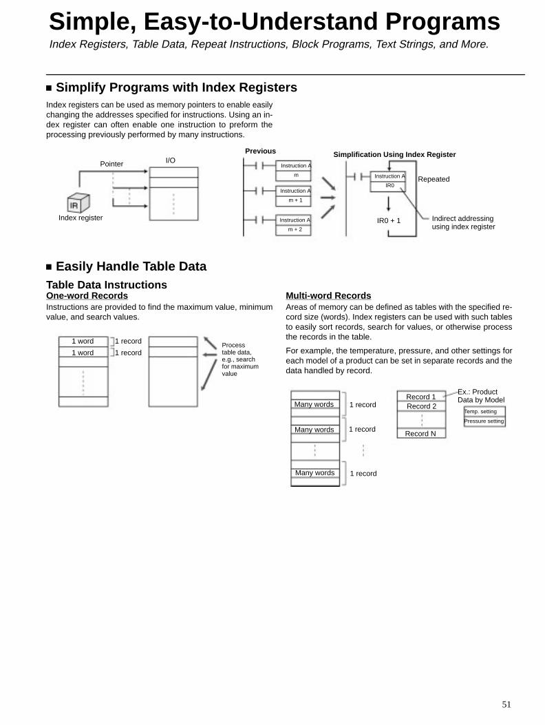
Simplify Programs with Index RegistersIndex registers can be used as memory pointers to enable easilychanging the addresses specified for instructions. Using an in-dex register can often enable one instruction to preform theprocessing previously performed by many instructions.
Pointer I/O
Index register
Previous Simplification Using Index RegisterInstruction A
m
Instruction A
m + 1
Instruction A
m + 2
Instruction A
IR0
IR0 + 1 Indirect addressingusing index register
Repeated
Easily Handle Table DataTable Data InstructionsOne-word RecordsInstructions are provided to find the maximum value, minimumvalue, and search values.
1 word
1 word
1 record
1 recordProcesstable data,e.g., searchfor maximumvalue
Multi-word RecordsAreas of memory can be defined as tables with the specified re-cord size (words). Index registers can be used with such tablesto easily sort records, search for values, or otherwise processthe records in the table.
For example, the temperature, pressure, and other settings foreach model of a product can be set in separate records and thedata handled by record.
Many words
Many words
Many words
1 record
1 record
1 recordRecord 1Record 2
Record N
Ex.: ProductData by Model
Temp. setting
Pressure setting
Simple, Easy-to-Understand ProgramsIndex Registers, Table Data, Repeat Instructions, Block Programs, Text Strings, and More.
Simple, Easy-to-Understand ProgramsIndex Registers, Table Data, Repeat Instructions, Block Programs, Text Strings, and More.
52
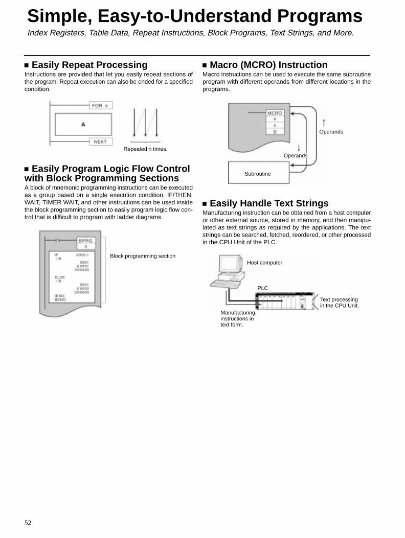
Easily Repeat ProcessingInstructions are provided that let you easily repeat sections ofthe program. Repeat execution can also be ended for a specifiedcondition.
Repeated n times.
Easily Program Logic Flow Controlwith Block Programming SectionsA block of mnemonic programming instructions can be executedas a group based on a single execution condition. IF/THEN,WAIT, TIMER WAIT, and other instructions can be used insidethe block programming section to easily program logic flow con-trol that is difficult to program with ladder diagrams.
Block programming section
Macro (MCRO) InstructionMacro instructions can be used to execute the same subroutineprogram with different operands from different locations in theprograms.
Operands
Operands
Subroutine
Easily Handle Text StringsManufacturing instruction can be obtained from a host computeror other external source, stored in memory, and then manipu-lated as text strings as required by the applications. The textstrings can be searched, fetched, reordered, or other processedin the CPU Unit of the PLC.
Host computer
PLC
Manufacturinginstructions intext form.
Text processingin the CPU Unit.
53
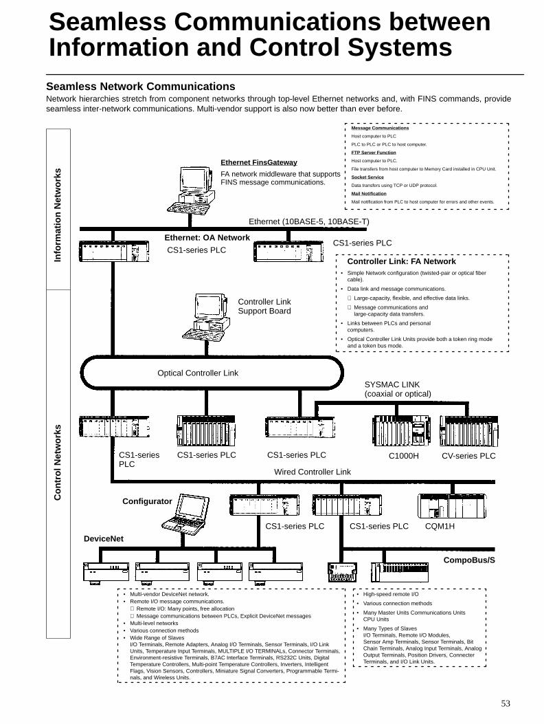
Seamless Network CommunicationsNetwork hierarchies stretch from component networks through top-level Ethernet networks and, with FINS commands, provideseamless inter-network communications. Multi-vendor support is also now better than ever before.
Info
rmat
ion
Net
wor
ksC
ontr
ol N
etw
orks
Ethernet: OA Network
Message Communications
Host computer to PLC
PLC to PLC or PLC to host computer.
FTP Server Function
Host computer to PLC.
File transfers from host computer to Memory Card installed in CPU Unit.
Socket Service
Data transfers using TCP or UDP protocol.
Mail Notification
Mail notification from PLC to host computer for errors and other events.
Ethernet FinsGateway
FA network middleware that supportsFINS message communications.
Configurator
Controller Link: FA Network• Simple Network configuration (twisted-pair or optical fiber
cable).
• Data link and message communications.
⋅ Large-capacity, flexible, and effective data links.
⋅ Message communications and large-capacity data transfers.
• Links between PLCs and personal computers.
• Optical Controller Link Units provide both a token ring modeand a token bus mode.
CS1-series PLC
Controller LinkSupport Board
CS1-series PLC
CS1-seriesPLC
CS1-series PLC CS1-series PLC
SYSMAC LINK(coaxial or optical)
C1000H CV-series PLC
CQM1H
Wired Controller Link
CompoBus/S
DeviceNet
• Multi-vendor DeviceNet network.• Remote I/O message communications.
⋅ Remote I/O: Many points, free allocation⋅ Message communications between PLCs, Explicit DeviceNet messages
• Multi-level networks• Various connection methods• Wide Range of Slaves
I/O Terminals, Remote Adapters, Analog I/O Terminals, Sensor Terminals, I/O LinkUnits, Temperature Input Terminals, MULTIPLE I/O TERMINALs, Connector Terminals,Environment-resistive Terminals, B7AC Interface Terminals, RS232C Units, DigitalTemperature Controllers, Multi-point Temperature Controllers, Inverters, IntelligentFlags, Vision Sensors, Controllers, Miniature Signal Converters, Programmable Termi-nals, and Wireless Units.
• High-speed remote I/O
• Various connection methods
• Many Master Units Communications UnitsCPU Units
• Many Types of SlavesI/O Terminals, Remote I/O Modules, Sensor Amp Terminals, Sensor Terminals, BitChain Terminals, Analog Input Terminals, AnalogOutput Terminals, Position Drivers, ConnecterTerminals, and I/O Link Units.
CS1-series PLCCS1-series PLC
Ethernet (10BASE-5, 10BASE-T)
Optical Controller Link
Seamless Communications betweenInformation and Control Systems
Seamless Communications betweenInformation and Control Systems
54
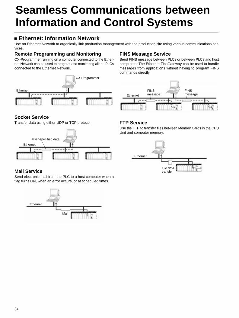
Ethernet: Information NetworkUse an Ethernet Network to organically link production management with the production site using various communications ser-vices.
Remote Programming and MonitoringCX-Programmer running on a computer connected to the Ether-net Network can be used to program and monitoring all the PLCsconnected to the Ethernet Network.
CX-Programmer
Ethernet
Socket ServiceTransfer data using either UDP or TCP protocol.
Ethernet
User-specified data
Mail ServiceSend electronic mail from the PLC to a host computer when aflag turns ON, when an error occurs, or at scheduled times.
Ethernet
FINS Message ServiceSend FINS message between PLCs or between PLCs and hostcomputers. The Ethernet FinsGateway can be used to handlemessages from applications without having to program FINScommands directly.
Ethernet
FINSmessage
FINSmessage
FTP ServiceUse the FTP to transfer files between Memory Cards in the CPUUnit and computer memory.
Ethernet
File datatransfer
Seamless Communications betweenInformation and Control Systems
55
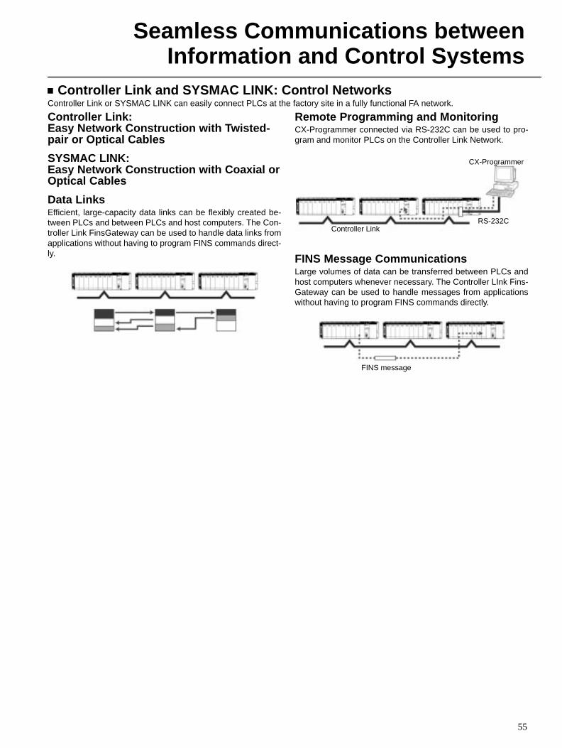
Controller Link and SYSMAC LINK: Control NetworksController Link or SYSMAC LINK can easily connect PLCs at the factory site in a fully functional FA network.
Controller Link:Easy Network Construction with Twisted-pair or Optical Cables
SYSMAC LINK:Easy Network Construction with Coaxial orOptical Cables
Data LinksEfficient, large-capacity data links can be flexibly created be-tween PLCs and between PLCs and host computers. The Con-troller Link FinsGateway can be used to handle data links fromapplications without having to program FINS commands direct-ly.
Remote Programming and MonitoringCX-Programmer connected via RS-232C can be used to pro-gram and monitor PLCs on the Controller Link Network.
Controller Link
CX-Programmer
RS-232C
FINS Message CommunicationsLarge volumes of data can be transferred between PLCs andhost computers whenever necessary. The Controller LInk Fins-Gateway can be used to handle messages from applicationswithout having to program FINS commands directly.
FINS message
Seamless Communications betweenInformation and Control Systems
56
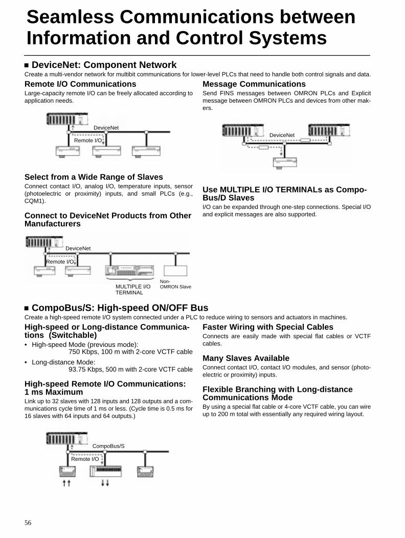
DeviceNet: Component NetworkCreate a multi-vendor network for multibit communications for lower-level PLCs that need to handle both control signals and data.
Remote I/O CommunicationsLarge-capacity remote I/O can be freely allocated according toapplication needs.
Remote I/O
DeviceNet
Select from a Wide Range of SlavesConnect contact I/O, analog I/O, temperature inputs, sensor(photoelectric or proximity) inputs, and small PLCs (e.g.,CQM1).
Connect to DeviceNet Products from OtherManufacturers
Remote I/O
DeviceNet
MULTIPLE I/OTERMINAL
Non-OMRON Slave
Message CommunicationsSend FINS messages between OMRON PLCs and Explicitmessage between OMRON PLCs and devices from other mak-ers.
DeviceNet
Use MULTIPLE I/O TERMINALs as Compo-Bus/D SlavesI/O can be expanded through one-step connections. Special I/Oand explicit messages are also supported.
CompoBus/S: High-speed ON/OFF BusCreate a high-speed remote I/O system connected under a PLC to reduce wiring to sensors and actuators in machines.
High-speed or Long-distance Communica-tions (Switchable)• High-speed Mode (previous mode):
750 Kbps, 100 m with 2-core VCTF cable
• Long-distance Mode: 93.75 Kbps, 500 m with 2-core VCTF cable
High-speed Remote I/O Communications:1 ms MaximumLink up to 32 slaves with 128 inputs and 128 outputs and a com-munications cycle time of 1 ms or less. (Cycle time is 0.5 ms for16 slaves with 64 inputs and 64 outputs.)
Remote I/O
CompoBus/S
Faster Wiring with Special CablesConnects are easily made with special flat cables or VCTFcables.
Many Slaves AvailableConnect contact I/O, contact I/O modules, and sensor (photo-electric or proximity) inputs.
Flexible Branching with Long-distanceCommunications ModeBy using a special flat cable or 4-core VCTF cable, you can wireup to 200 m total with essentially any required wiring layout.
57
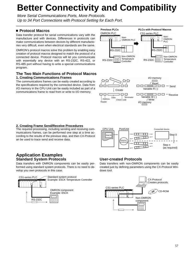
Protocol MacrosData transfer protocol for serial communications vary with themanufacture and with devices. Differences in protocols canmake communications between devices by different manufacto-ries very difficult, even when electrical standards are the same.
OMRON’s protocol macros solve this problem by enabling easycreation of protocol macros designed to match the protocol of aconnected device. Protocol macros will let you communicatewith essentially any device with an RS-232C, RS-422, orRS-485 port without having to write a special communicationsprogram.
Previous PLCs PLCs with Protocol Macros
Non-OMRON PLC
RS-232C
Non-OMRONTemperatureControllerRS-232C RS-232C
RS-232C
Non-OMRONPLC
Non-OMRONTemperatureController
OMRON PLC CS1-series PLC
The Two Main Functions of Protocol Macros1. Creating Communications FramesThe communications frames can be easily created according tothe specifications required by the connected device. Data fromI/O memory in the CPU Unit can be easily included as part of acommunications frame to read from or write to I/O memory.
I/O memory
Read
Variable R ( )Send
ReceiveVariable W ( )
WriteI/O memory
Create
Header
AddressData
Check codeTerminator
2. Creating Frame Send/Receive ProceduresThe required processing, including sending and receiving com-munications frames, can be performed one step at a time ac-cording to the results of the previous step, and then CX-Protocolan be used to trace send and receive data.
CPU Unit
PMCR
Port/Unit
Requiredprocessing
Connected device
Step 0
Step n (as required)
Application ExamplesStandard System ProtocolsData transfers with OMRON components can be easily per-formed using standard system protocols. There is no need to de-velop you own protocols in this case.
CS1-series PLC Standard system protocolExample: E5CK Temperature Controller
RS-232C
OMRON componentExample: E5CK
User-created ProtocolsData transfers with non-OMRON components can be easilycreated just by defining parameters using the CX-Protocol Win-dows tool.
CX-ProtocolCreates protocols.
CD-ROMCS1-series PLC
Non-OMRONcomponent
Better Connectivity and CompatibilityMore Serial Communications Ports, More Protocols.Up to 34 Port Connections with Protocol Setting for Each Port.
Better Connectivity and Compatibility
58
Other ProtocolsOMRON provides all of the capabilities and capacity you need for the advanced programming required for human-machine inter-faces, communications, data processing, and other required applications.• Host Links
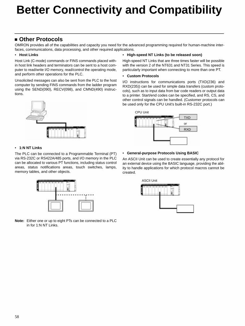
Host Link (C-mode) commands or FINS commands placed with-in host link headers and terminators can be sent to a host com-puter to read/write I/O memory, read/control the operating mode,and perform other operations for the PLC.
Unsolicited messages can also be sent from the PLC to the hostcomputer by sending FINS commands from the ladder programusing the SEND(090), RECV(098), and CMND(490) instruc-tions.
• 1:N NT Links
The PLC can be connected to a Programmable Terminal (PT)via RS-232C or RS422A/485 ports, and I/O memory in the PLCcan be allocated to various PT functions, including status controlareas, status notifications areas, touch switches, lamps,memory tables, and other objects.
Note: Either one or up to eight PTs can be connected to a PLCin for 1:N NT Links.
• High-speed NT Links (to be released soon)
High-speed NT Links that are three times faster will be possiblewith the version 2 of the NT631 and NT31 Series. This speed isparticularly important when connecting to more than one PT.
• Custom Protocols
I/O instructions for communications ports (TXD(236) andRXD(235)) can be used for simple data transfers (custom proto-cols), such as to input data from bar code readers or output datato a printer. Start/end codes can be specified, and RS, CS, andother control signals can be handled. (Customer protocols canbe used only for the CPU Unit’s built-in RS-232C port.)
TXD
or
RXD
CPU Unit
• General-purpose Protocols Using BASIC
An ASCII Unit can be used to create essentially any protocol foran external device using the BASIC language, providing the abil-ity to handle applications for which protocol macros cannot becreated.
ASCII Unit
Better Connectivity and Compatibility
59
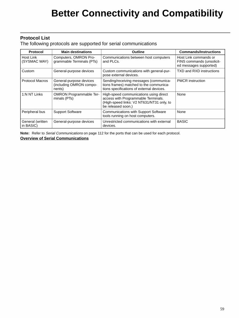
Protocol ListThe following protocols are supported for serial communications
Protocol Main destinations Outline Commands/Instructions
Host Link (SYSMAC WAY)
Computers, OMRON Pro-grammable Terminals (PTs)
Communications between host computersand PLCs.
Host Link commands orFINS commands (unsolicit-ed messages supported)
Custom General-purpose devices Custom communications with general-pur-pose external devices.
TXD and RXD instructions
Protocol Macros General-purpose devices(including OMRON compo-nents)
Sending/receiving messages (communica-tions frames) matched to the communica-tions specifications of external devices.
PMCR instruction
1:N NT Links OMRON Programmable Ter-minals (PTs)
High-speed communications using directaccess with Programmable Terminals.(High-speed links: V2 NT631/NT31 only, tobe released soon.)
None
Peripheral bus Support Software Communications with Support Softwaretools running on host computers.
None
General (writtenin BASIC)
General-purpose devices Unrestricted communications with externaldevices.
BASIC
Note: Refer to Serial Communications on page 112 for the ports that can be used for each protocol.
Overview of Serial Communications
Better Connectivity and Compatibility
60
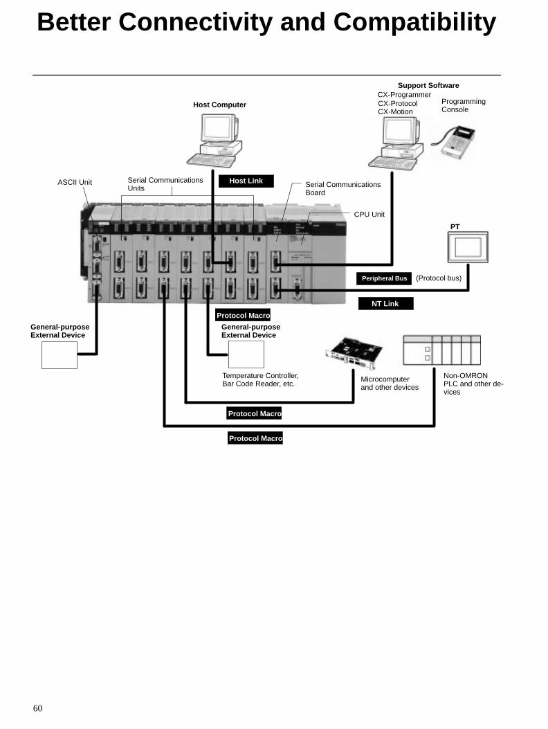
Host Computer
Host Link
General-purposeExternal Device
Microcomputerand other devices
Non-OMRONPLC and other de-vices
PT
Serial CommunicationsBoard
CPU Unit
Support SoftwareCX-ProgrammerCX-ProtocolCX-Motion
ProgrammingConsole
ASCII Unit Serial CommunicationsUnits
Peripheral Bus (Protocol bus)
NT Link
Protocol Macro
General-purposeExternal Device
Temperature Controller,Bar Code Reader, etc.
Protocol Macro
Protocol Macro
61
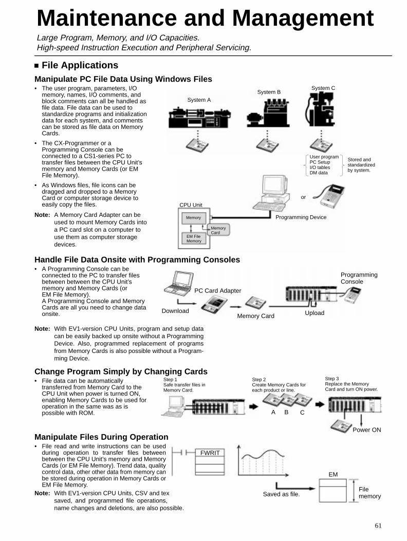
File ApplicationsManipulate PC File Data Using Windows Files• The user program, parameters, I/O
memory, names, I/O comments, andblock comments can all be handled asfile data. File data can be used tostandardize programs and initializationdata for each system, and commentscan be stored as file data on MemoryCards.
• The CX-Programmer or aProgramming Console can beconnected to a CS1-series PC totransfer files between the CPU Unit’smemory and Memory Cards (or EMFile Memory).
• As Windows files, file icons can bedragged and dropped to a MemoryCard or computer storage device toeasily copy the files.
Note: A Memory Card Adapter can beused to mount Memory Cards intoa PC card slot on a computer touse them as computer storagedevices.
Handle File Data Onsite with Programming Consoles• A Programming Console can be
connected to the PC to transfer filesbetween between the CPU Unit’smemory and Memory Cards (orEM File Memory). A Programming Console and MemoryCards are all you need to change dataonsite.
Note: With EV1-version CPU Units, program and setup datacan be easily backed up onsite without a ProgrammingDevice. Also, programmed replacement of programsfrom Memory Cards is also possible without a Program-ming Device.
Change Program Simply by Changing Cards• File data can be automatically
transferred from Memory Card to theCPU Unit when power is turned ON,enabling Memory Cards to be used foroperation in the same was as ispossible with ROM.
Manipulate Files During Operation• File read and write instructions can be used
during operation to transfer files betweenbetween the CPU Unit’s memory and MemoryCards (or EM File Memory). Trend data, qualitycontrol data, other other data from memory canbe stored during operation in Memory Cards orEM File Memory.
Note: With EV1-version CPU Units, CSV and text files can besaved, and programmed file operations, such as filename changes and deletions, are also possible.
Maintenance and ManagementLarge Program, Memory, and I/O Capacities. High-speed Instruction Execution and Peripheral Servicing.
System A
System CSystem B
User programPC SetupI/O tablesDM data
Stored andstandardizedby system.
CPU Unit
Memory
EM FileMemory
MemoryCard
or
Programming Device
Download
PC Card Adapter
Memory Card Upload
ProgrammingConsole
Step 1Safe transfer files inMemory Card.
Step 2Create Memory Cards foreach product or line.
Step 3Replace the MemoryCard and turn ON power.
Power ON
A B C
Saved as file.
EM
Filememory
FWRIT
Maintenance and Management
62
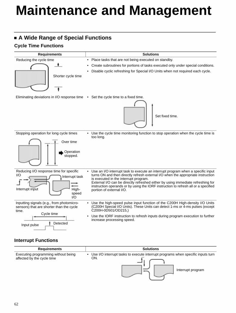
A Wide Range of Special FunctionsCycle Time Functions
Requirements Solutions
Shorter cycle time
Reducing the cycle time • Place tasks that are not being executed on standby.
• Create subroutines for portions of tasks executed only under special conditions.
• Disable cyclic refreshing for Special I/O Units when not required each cycle.
Eliminating deviations in I/O response time • Set the cycle time to a fixed time.
Set fixed time.
Stopping operation for long cycle times
Over time
Operationstopped.
• Use the cycle time monitoring function to stop operation when the cycle time istoo long.
Reducing I/O response time for specificI/O
Interrupt input
Interrupt task
High-speedI/O
• Use an I/O interrupt task to execute an interrupt program when a specific inputturns ON and then directly refresh external I/O when the appropriate instructionis executed in the interrupt program. External I/O can be directly refreshed either by using immediate refreshing forinstruction operands or by using the IORF instruction to refresh all or a specifiedportion of external I/O.
Inputting signals (e.g., from photomicro-sensors) that are shorter than the cycletime.
Cycle time
Input pulse Detected
• Use the high-speed pulse input function of the C200H High-density I/O Units(C200H Special I/O Units). These Units can detect 1-ms or 4-ms pulses (exceptC200H-0D501/OD215,)
• Use the IORF instruction to refresh inputs during program execution to furtherincrease processing speed.
Interrupt Functions
Requirements Solutions
Executing programming without beingaffected by the cycle time
• Use I/O interrupt tasks to execute interrupt programs when specific inputs turnON.
Interrupt program
Maintenance and Management
63
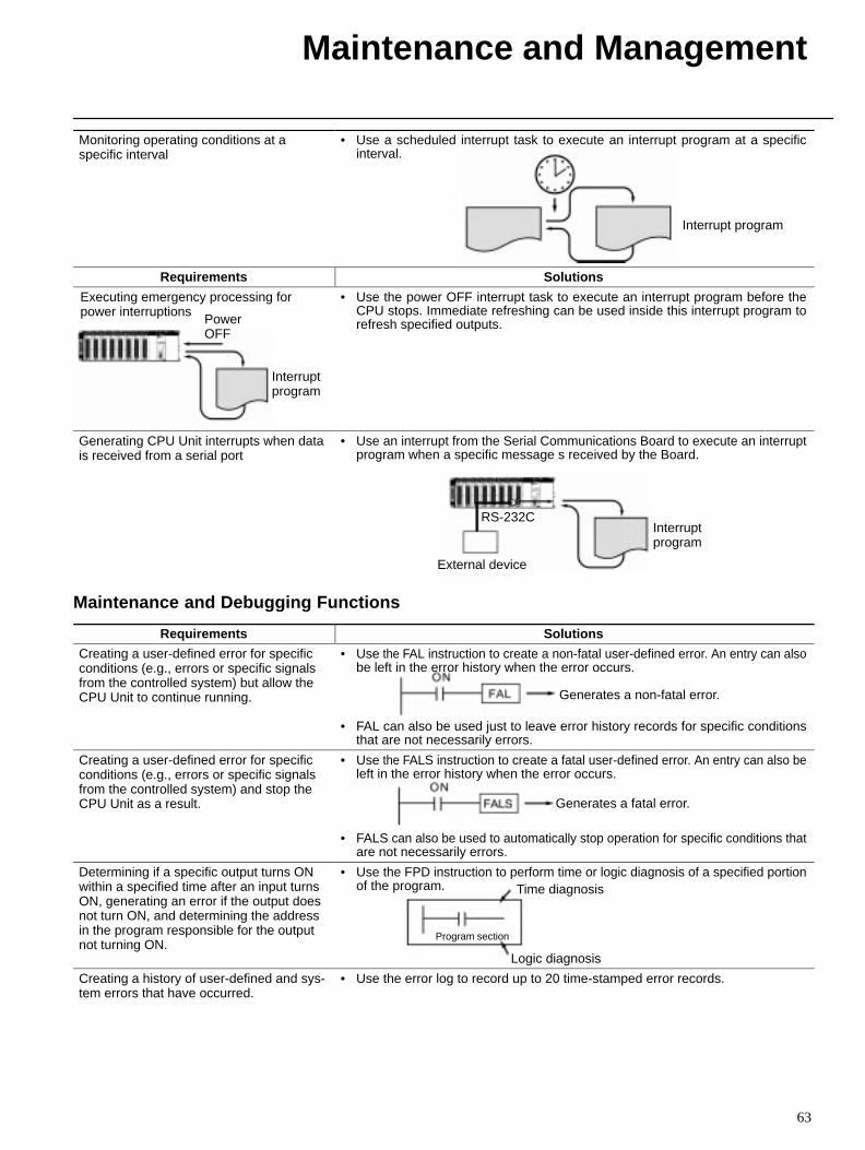
Monitoring operating conditions at aspecific interval
• Use a scheduled interrupt task to execute an interrupt program at a specificinterval.
Interrupt program
Requirements Solutions
Executing emergency processing forpower interruptions
PowerOFF
Interrupt program
• Use the power OFF interrupt task to execute an interrupt program before theCPU stops. Immediate refreshing can be used inside this interrupt program torefresh specified outputs.
Generating CPU Unit interrupts when datais received from a serial port
• Use an interrupt from the Serial Communications Board to execute an interruptprogram when a specific message s received by the Board.
RS-232C
External device
Interruptprogram
Maintenance and Debugging Functions
Requirements Solutions
Creating a user-defined error for specificconditions (e.g., errors or specific signalsfrom the controlled system) but allow theCPU Unit to continue running.
• Use the FAL instruction to create a non-fatal user-defined error. An entry can alsobe left in the error history when the error occurs.
• FAL can also be used just to leave error history records for specific conditionsthat are not necessarily errors.
Generates a non-fatal error.
Creating a user-defined error for specificconditions (e.g., errors or specific signalsfrom the controlled system) and stop theCPU Unit as a result.
• Use the FALS instruction to create a fatal user-defined error. An entry can also beleft in the error history when the error occurs.
• FALS can also be used to automatically stop operation for specific conditions thatare not necessarily errors.
Generates a fatal error.
Determining if a specific output turns ONwithin a specified time after an input turnsON, generating an error if the output doesnot turn ON, and determining the addressin the program responsible for the outputnot turning ON.
• Use the FPD instruction to perform time or logic diagnosis of a specified portionof the program. Time diagnosis
Logic diagnosis
Program section
Creating a history of user-defined and sys-tem errors that have occurred.
• Use the error log to record up to 20 time-stamped error records.
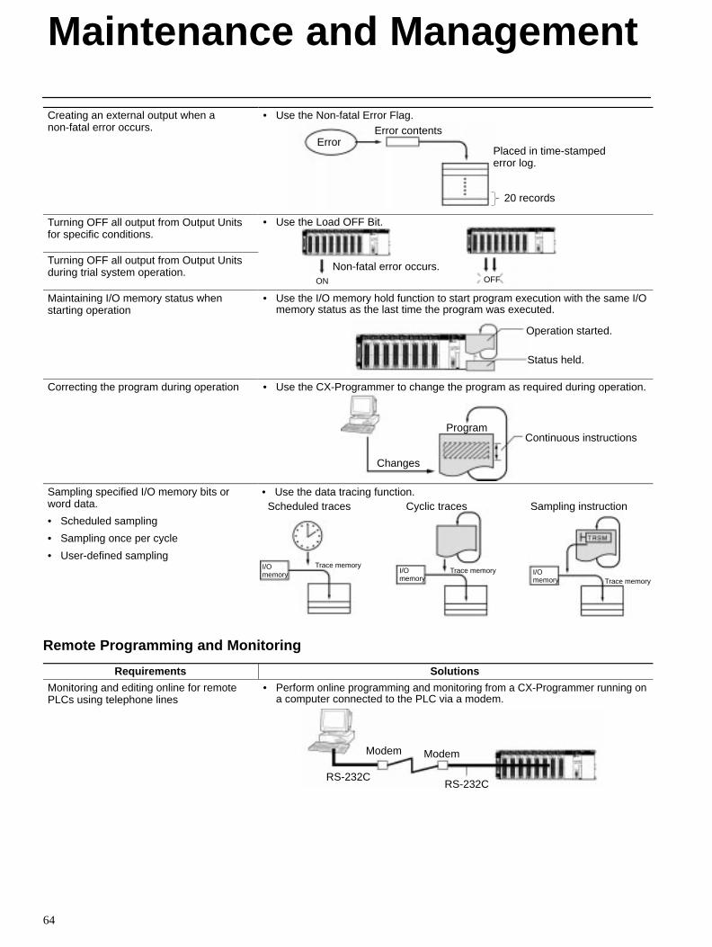
Maintenance and Management
64
Creating an external output when anon-fatal error occurs.
• Use the Non-fatal Error Flag.
ErrorError contents
Placed in time-stamped error log.
20 records
Turning OFF all output from Output Unitsfor specific conditions.
• Use the Load OFF Bit.
Turning OFF all output from Output Unitsduring trial system operation. Non-fatal error occurs.
ON OFF
Maintaining I/O memory status whenstarting operation
• Use the I/O memory hold function to start program execution with the same I/Omemory status as the last time the program was executed.
Status held.
Operation started.
Correcting the program during operation • Use the CX-Programmer to change the program as required during operation.
Changes
ProgramContinuous instructions
Sampling specified I/O memory bits orword data.
• Scheduled sampling
• Sampling once per cycle
• User-defined sampling
• Use the data tracing function.Scheduled traces Cyclic traces Sampling instruction
I/Omemory
Trace memoryI/Omemory
Trace memory I/Omemory Trace memory
Remote Programming and Monitoring
Requirements Solutions
Monitoring and editing online for remotePLCs using telephone lines
• Perform online programming and monitoring from a CX-Programmer running ona computer connected to the PLC via a modem.
Modem Modem
RS-232CRS-232C
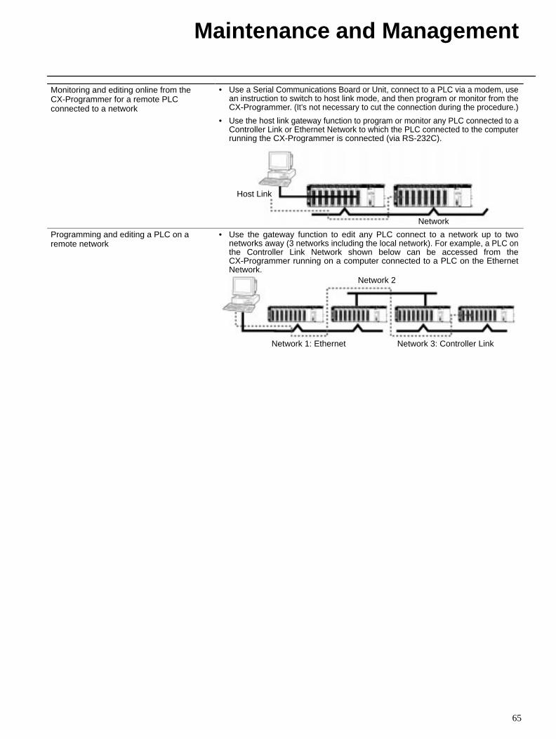
Maintenance and Management
65
Monitoring and editing online from theCX-Programmer for a remote PLCconnected to a network
• Use a Serial Communications Board or Unit, connect to a PLC via a modem, usean instruction to switch to host link mode, and then program or monitor from theCX-Programmer. (It’s not necessary to cut the connection during the procedure.)
• Use the host link gateway function to program or monitor any PLC connected to aController Link or Ethernet Network to which the PLC connected to the computerrunning the CX-Programmer is connected (via RS-232C).
Host Link
Network
Programming and editing a PLC on aremote network
• Use the gateway function to edit any PLC connect to a network up to twonetworks away (3 networks including the local network). For example, a PLC onthe Controller Link Network shown below can be accessed from theCX-Programmer running on a computer connected to a PLC on the EthernetNetwork.
Network 2
Network 1: Ethernet Network 3: Controller Link
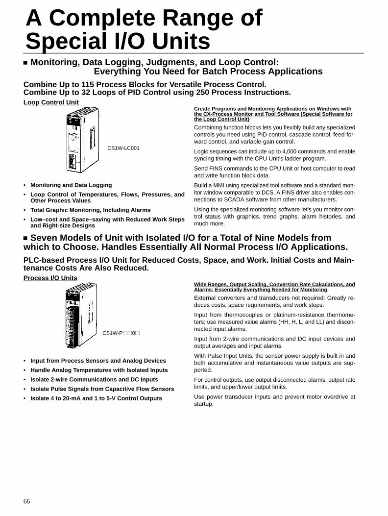
66
Monitoring, Data Logging, Judgments, and Loop Control: Everything You Need for Batch Process Applications
Combine Up to 115 Process Blocks for Versatile Process Control.Combine Up to 32 Loops of PID Control using 250 Process Instructions.Loop Control Unit
CS1W-LC001
• Monitoring and Data Logging
• Loop Control of Temperatures, Flows, Pressures, andOther Process Values
• Total Graphic Monitoring, Including Alarms
• Low–cost and Space–saving with Reduced Work Stepsand Right-size Designs
Create Programs and Monitoring Applications on W indows withthe CX-Process Monitor and T ool Software (Special Software forthe Loop Control Unit)
Combining function blocks lets you flexibly build any specializedcontrols you need using PID control, cascade control, feed-for-ward control, and variable-gain control.
Logic sequences can include up to 4,000 commands and enablesyncing timing with the CPU Unit’s ladder program.
Send FINS commands to the CPU Unit or host computer to readand write function block data.
Build a MMI using specialized tool software and a standard mon-itor window comparable to DCS. A FINS driver also enables con-nections to SCADA software from other manufacturers.
Using the specialized monitoring software let’s you monitor con-trol status with graphics, trend graphs, alarm histories, andmuch more.
Seven Models of Unit with Isolated I/O for a Total of Nine Models fromwhich to Choose. Handles Essentially All Normal Process I/O Applications.PLC-based Process I/O Unit for Reduced Costs, Space, and Work. Initial Costs and Main-tenance Costs Are Also Reduced.Process I/O Units
CS1W-P0
• Input from Process Sensors and Analog Devices
• Handle Analog Temperatures with Isolated Inputs
• Isolate 2-wire Communications and DC Inputs
• Isolate Pulse Signals from Capacitive Flow Sensors
• Isolate 4 to 20-mA and 1 to 5-V Control Outputs
Wide Ranges, Output Scaling, Conversion Rate Calculations, andAlarms: Essentially Everything Needed for Monitoring
External converters and transducers not required: Greatly re-duces costs, space requirements, and work steps.
Input from thermocouples or platinum-resistance thermome-ters; use measured value alarms (HH, H, L, and LL) and discon-nected input alarms.
Input from 2-wire communications and DC input devices andoutput averages and input alarms.
With Pulse Input Units, the sensor power supply is built in andboth accumulative and instantaneous value outputs are sup-ported.
For control outputs, use output disconnected alarms, output ratelimits, and upper/lower output limits.
Use power transducer inputs and prevent motor overdrive atstartup.
A Complete Range ofSpecial I/O Units
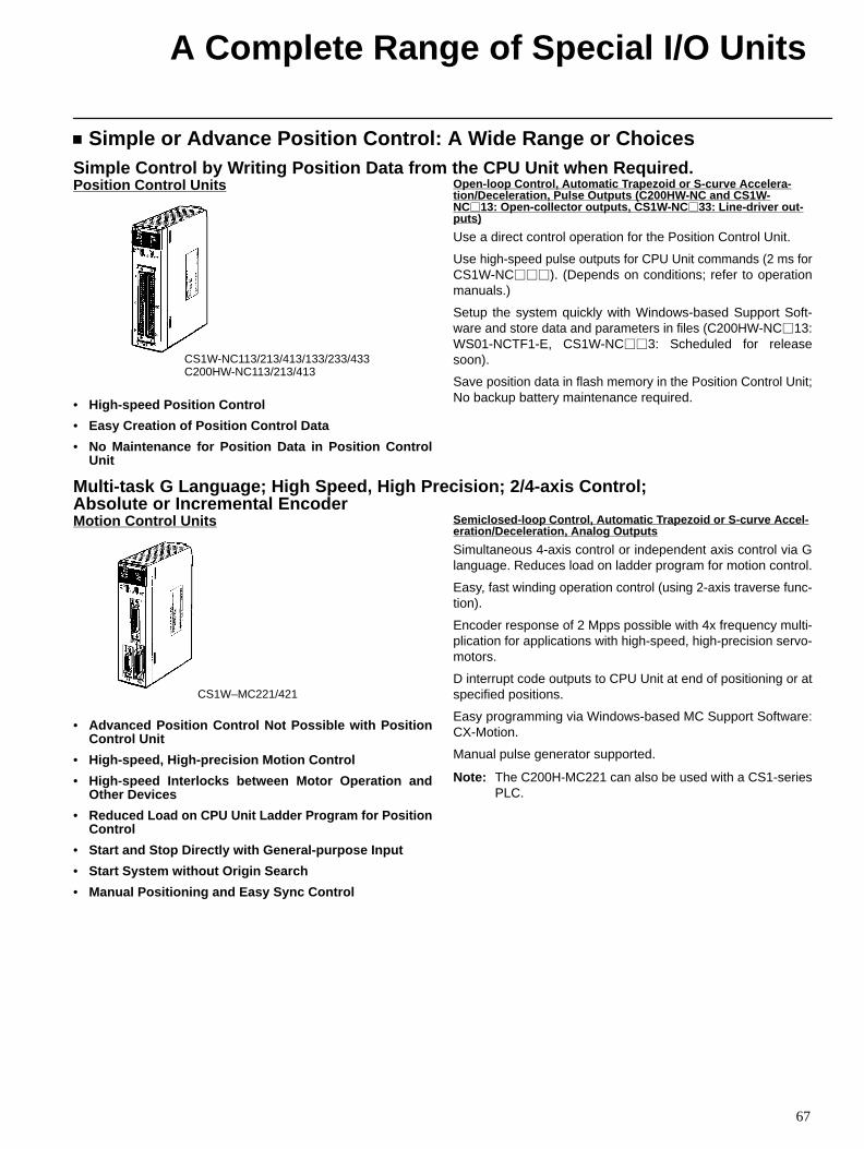
A Complete Range of Special I/O Units
67
Simple or Advance Position Control: A Wide Range or ChoicesSimple Control by Writing Position Data from the CPU Unit when Required.Position Control Units
CS1W-NC113/213/413/133/233/433C200HW-NC113/213/413
• High-speed Position Control
• Easy Creation of Position Control Data
• No Maintenance for Position Data in Position ControlUnit
Open-loop Control, Automatic T rapezoid or S-curve Accelera -tion/Deceleration, Pulse Outputs (C200HW -NC and CS1W-NC13: Open-collector outputs, CS1W -NC33: Line-driver out -puts)
Use a direct control operation for the Position Control Unit.
Use high-speed pulse outputs for CPU Unit commands (2 ms forCS1W-NC). (Depends on conditions; refer to operationmanuals.)
Setup the system quickly with Windows-based Support Soft-ware and store data and parameters in files (C200HW-NC13:WS01-NCTF1-E, CS1W-NC3: Scheduled for releasesoon).
Save position data in flash memory in the Position Control Unit;No backup battery maintenance required.
Multi-task G Language; High Speed, High Precision; 2/4-axis Control; Absolute or Incremental EncoderMotion Control Units
CS1W–MC221/421
• Advanced Position Control Not Possible with PositionControl Unit
• High-speed, High-precision Motion Control
• High-speed Interlocks between Motor Operation andOther Devices
• Reduced Load on CPU Unit Ladder Program for PositionControl
• Start and Stop Directly with General-purpose Input
• Start System without Origin Search
• Manual Positioning and Easy Sync Control
Semiclosed-loop Control, Automatic T rapezoid or S-curve Accel -eration/Deceleration, Analog Outputs
Simultaneous 4-axis control or independent axis control via Glanguage. Reduces load on ladder program for motion control.
Easy, fast winding operation control (using 2-axis traverse func-tion).
Encoder response of 2 Mpps possible with 4x frequency multi-plication for applications with high-speed, high-precision servo-motors.
D interrupt code outputs to CPU Unit at end of positioning or atspecified positions.
Easy programming via Windows-based MC Support Software:CX-Motion.
Manual pulse generator supported.
Note: The C200H-MC221 can also be used with a CS1-seriesPLC.
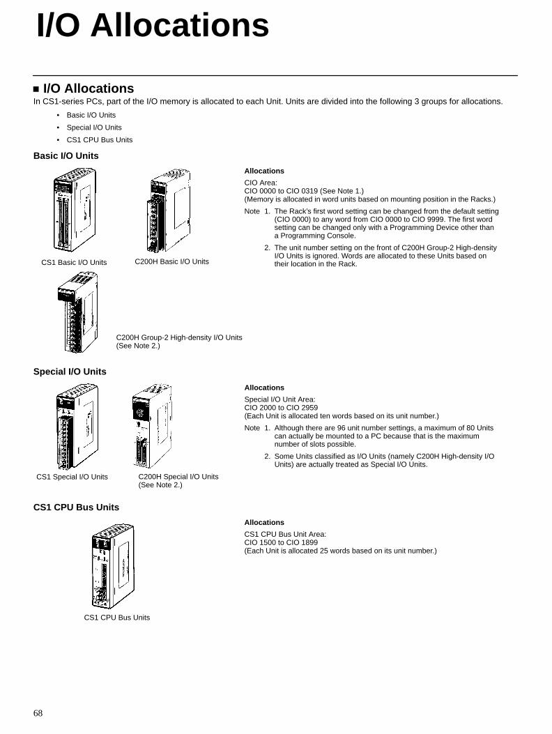
68
I/O AllocationsIn CS1-series PCs, part of the I/O memory is allocated to each Unit. Units are divided into the following 3 groups for allocations.
• Basic I/O Units
• Special I/O Units
• CS1 CPU Bus Units
Basic I/O Units
CS1 Basic I/O Units C200H Basic I/O Units
C200H Group-2 High-density I/O Units(See Note 2.)
Allocations
CIO Area:CIO 0000 to CIO 0319 (See Note 1.)(Memory is allocated in word units based on mounting position in the Racks.)
Note 1. The Rack’s first word setting can be changed from the default setting(CIO 0000) to any word from CIO 0000 to CIO 9999. The first wordsetting can be changed only with a Programming Device other thana Programming Console.
2. The unit number setting on the front of C200H Group-2 High-densityI/O Units is ignored. Words are allocated to these Units based ontheir location in the Rack.
Special I/O Units
CS1 Special I/O Units C200H Special I/O Units(See Note 2.)
Allocations
Special I/O Unit Area:CIO 2000 to CIO 2959(Each Unit is allocated ten words based on its unit number.)
Note 1. Although there are 96 unit number settings, a maximum of 80 Unitscan actually be mounted to a PC because that is the maximumnumber of slots possible.
2. Some Units classified as I/O Units (namely C200H High-density I/OUnits) are actually treated as Special I/O Units.
CS1 CPU Bus Units
CS1 CPU Bus Units
Allocations
CS1 CPU Bus Unit Area:CIO 1500 to CIO 1899(Each Unit is allocated 25 words based on its unit number.)
I/O Allocations
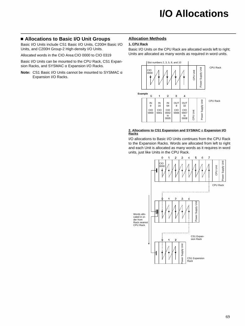
I/O Allocations
69
Allocations to Basic I/O Unit GroupsBasic I/O Units include CS1 Basic I/O Units, C200H Basic I/OUnits, and C200H Group-2 High-density I/O Units.
Allocated words in the CIO Area:CIO 0000 to CIO 0319
Basic I/O Units can be mounted to the CPU Rack, CS1 Expan-sion Racks, and SYSMAC α Expansion I/O Racks.
Note: CS1 Basic I/O Units cannot be mounted to SYSMAC αExpansion I/O Racks.
Allocation Methods1. CPU Rack
Basic I/O Units on the CPU Rack are allocated words left to right;Units are allocated as many words as required in word units.
Slot numbers 2, 3, 5, 8, and 10
CPU RackCIO0000
CP
U U
nit
Pow
er S
uppl
y U
nit
CPU RackIN8
CIO0000
IN16
CIO0001
IN64
CIO0002
to0005
OUT8
CIO0006
OUT32
CIO0007
to0008 C
PU
Uni
t
Pow
er S
uppl
y U
nit
Example
2. Allocations to CS1 Expansion and SYSMAC α Expansion I/ORacks
I/O allocations to Basic I/O Units continues from the CPU Rackto the Expansion Racks. Words are allocated from left to rightand each Unit is allocated as many words as it requires in wordunits, just like Units in the CPU Rack.
CPU Rack
CS1 Expan-sion Rack
CS1 ExpansionRack
Words allo-cated in or-der fromRack nearestCPU Rack.
CP
U U
nit
Pow
er S
uppl
y U
nit
CIO0000
Pow
er S
uppl
y U
nit
Pow
er S
uppl
y U
nit
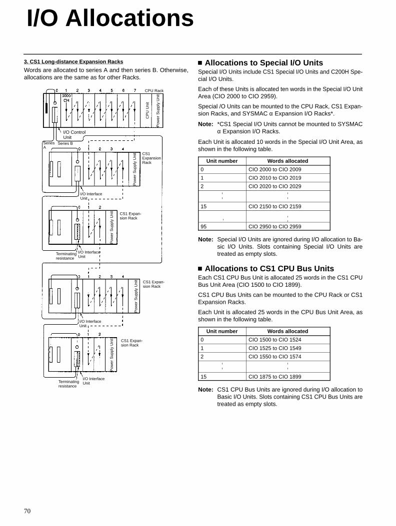
I/O Allocations
70
3. CS1 Long-distance Expansion Racks
Words are allocated to series A and then series B. Otherwise,allocations are the same as for other Racks.
CPU Rack
CS1ExpansionRack
CP
U U
nit
Pow
er S
uppl
y U
nit
Pow
er S
uppl
y U
nit
CS1 Expan-sion Rack
Pow
er S
uppl
y U
nit
CS1 Expan-sion Rack
Pow
er S
uppl
y U
nit
CS1 Expan-sion Rack
Pow
er S
uppl
y U
nit
Terminatingresistance
Terminatingresistance
I/O ControlUnit
I/O InterfaceUnit
I/O InterfaceUnit
I/O InterfaceUnit
I/O InterfaceUnit
SeriesA
Series B
Allocations to Special I/O UnitsSpecial I/O Units include CS1 Special I/O Units and C200H Spe-cial I/O Units.
Each of these Units is allocated ten words in the Special I/O UnitArea (CIO 2000 to CIO 2959).
Special /O Units can be mounted to the CPU Rack, CS1 Expan-sion Racks, and SYSMAC α Expansion I/O Racks*.
Note: *CS1 Special I/O Units cannot be mounted to SYSMACα Expansion I/O Racks.
Each Unit is allocated 10 words in the Special I/O Unit Area, asshown in the following table.
Unit number Words allocated
0 CIO 2000 to CIO 2009
1 CIO 2010 to CIO 2019
2 CIO 2020 to CIO 2029
15 CIO 2150 to CIO 2159
95 CIO 2950 to CIO 2959
Note: Special I/O Units are ignored during I/O allocation to Ba-sic I/O Units. Slots containing Special I/O Units aretreated as empty slots.
Allocations to CS1 CPU Bus UnitsEach CS1 CPU Bus Unit is allocated 25 words in the CS1 CPUBus Unit Area (CIO 1500 to CIO 1899).
CS1 CPU Bus Units can be mounted to the CPU Rack or CS1Expansion Racks.
Each Unit is allocated 25 words in the CPU Bus Unit Area, asshown in the following table.
Unit number Words allocated
0 CIO 1500 to CIO 1524
1 CIO 1525 to CIO 1549
2 CIO 1550 to CIO 1574
15 CIO 1875 to CIO 1899
Note: CS1 CPU Bus Units are ignored during I/O allocation toBasic I/O Units. Slots containing CS1 CPU Bus Units aretreated as empty slots.
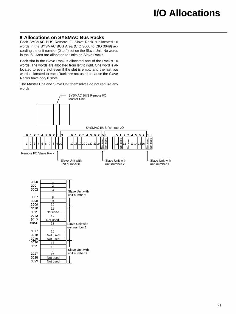
I/O Allocations
71
Allocations on SYSMAC Bus RacksEach SYSMAC BUS Remote I/O Slave Rack is allocated 10words in the SYSMAC BUS Area (CIO 3000 to CIO 3049) ac-cording the unit number (0 to 4) set on the Slave Unit. No wordsin the I/O Area are allocated to Units on Slave Racks.
Each slot in the Slave Rack is allocated one of the Rack’s 10words. The words are allocated from left to right. One word is al-located to every slot even if the slot is empty and the last twowords allocated to each Rack are not used because the SlaveRacks have only 8 slots.
The Master Unit and Slave Unit themselves do not require anywords.
Remote I/O Slave Rack
Slave Unit withunit number 0
SYSMAC BUS Remote I/O
SYSMAC BUS Remote I/OMaster Unit
Slave Unit withunit number 2
Slave Unit withunit number 1
Slave Unit withunit number 0
Slave Unit withunit number 1
Slave Unit withunit number 2
Not used.
123:8
Not used.
11
:16
Not used.Not used.
1718:
24Not used.Not used.
:
:
:
Not
use
dN
ot u
sed
Not
use
dN
ot u
sed
Not
use
d
Not
use
d
910
12
13
1 2 3 4 5 6 7 8 9 10 17 18 19 20 21 22 23 24 11 12 13 14 15 16
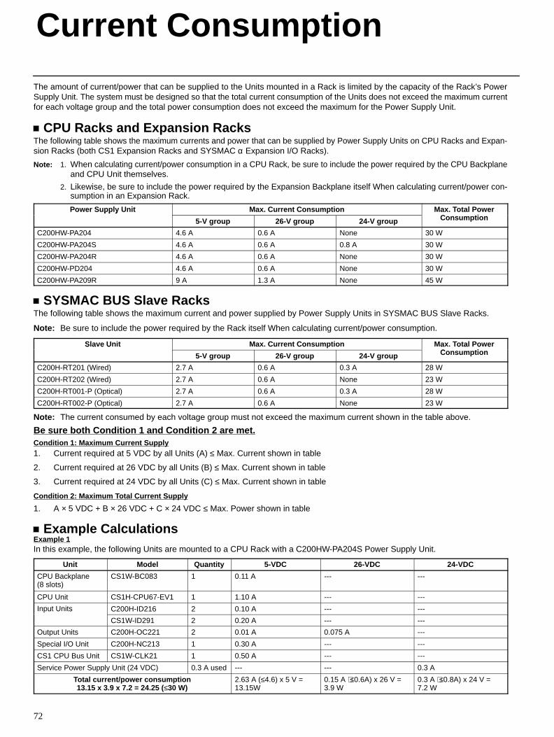
72
The amount of current/power that can be supplied to the Units mounted in a Rack is limited by the capacity of the Rack’s PowerSupply Unit. The system must be designed so that the total current consumption of the Units does not exceed the maximum currentfor each voltage group and the total power consumption does not exceed the maximum for the Power Supply Unit.
CPU Racks and Expansion RacksThe following table shows the maximum currents and power that can be supplied by Power Supply Units on CPU Racks and Expan-sion Racks (both CS1 Expansion Racks and SYSMAC α Expansion I/O Racks).
Note: 1. When calculating current/power consumption in a CPU Rack, be sure to include the power required by the CPU Backplaneand CPU Unit themselves.
2. Likewise, be sure to include the power required by the Expansion Backplane itself When calculating current/power con-sumption in an Expansion Rack.
Power Supply Unit Max. Current Consumption Max. Total PowerC ti
o e Supp y U
5-V group 26-V group 24-V group
a o a o eConsumption
C200HW-PA204 4.6 A 0.6 A None 30 W
C200HW-PA204S 4.6 A 0.6 A 0.8 A 30 W
C200HW-PA204R 4.6 A 0.6 A None 30 W
C200HW-PD204 4.6 A 0.6 A None 30 W
C200HW-PA209R 9 A 1.3 A None 45 W
SYSMAC BUS Slave RacksThe following table shows the maximum current and power supplied by Power Supply Units in SYSMAC BUS Slave Racks.
Note: Be sure to include the power required by the Rack itself When calculating current/power consumption.
Slave Unit Max. Current Consumption Max. Total PowerC ti
S a e U
5-V group 26-V group 24-V group
a o a o eConsumption
C200H-RT201 (Wired) 2.7 A 0.6 A 0.3 A 28 W
C200H-RT202 (Wired) 2.7 A 0.6 A None 23 W
C200H-RT001-P (Optical) 2.7 A 0.6 A 0.3 A 28 W
C200H-RT002-P (Optical) 2.7 A 0.6 A None 23 W
Note: The current consumed by each voltage group must not exceed the maximum current shown in the table above.
Be sure both Condition 1 and Condition 2 are met.Condition 1: Maximum Current Supply1. Current required at 5 VDC by all Units (A) ≤ Max. Current shown in table
2. Current required at 26 VDC by all Units (B) ≤ Max. Current shown in table
3. Current required at 24 VDC by all Units (C) ≤ Max. Current shown in table
Condition 2: Maximum T otal Current Supply
1. A × 5 VDC + B × 26 VDC + C × 24 VDC ≤ Max. Power shown in table
Example CalculationsExample 1In this example, the following Units are mounted to a CPU Rack with a C200HW-PA204S Power Supply Unit.
Unit Model Quantity 5-VDC 26-VDC 24-VDC
CPU Backplane (8 slots)
CS1W-BC083 1 0.11 A --- ---
CPU Unit CS1H-CPU67-EV1 1 1.10 A --- ---
Input Units C200H-ID216 2 0.10 A --- ---u U s
CS1W-ID291 2 0.20 A --- ---
Output Units C200H-OC221 2 0.01 A 0.075 A ---
Special I/O Unit C200H-NC213 1 0.30 A --- ---
CS1 CPU Bus Unit CS1W-CLK21 1 0.50 A --- ---
Service Power Supply Unit (24 VDC) 0.3 A used --- --- 0.3 A
Total current/power consumption13.15 x 3.9 x 7.2 = 24.25 (≤30 W)
2.63 A (≤4.6) x 5 V =13.15W
0.15 A ⟨≤0.6A) x 26 V =3.9 W
0.3 A ⟨≤0.8A) x 24 V =7.2 W
Current Consumption
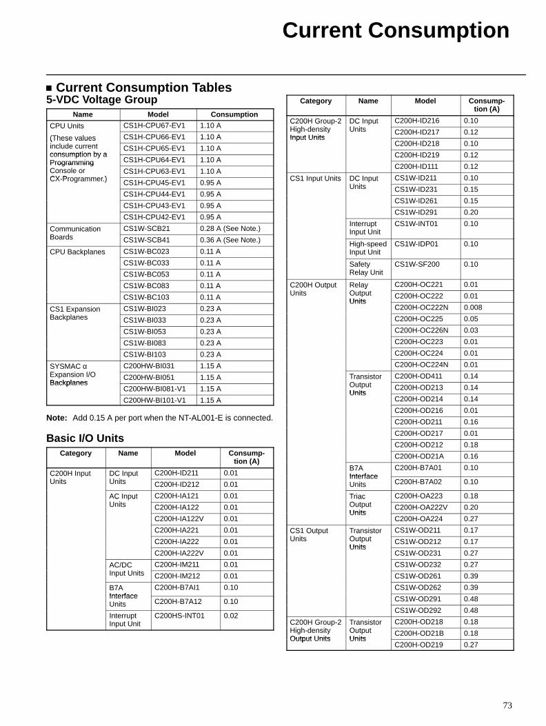
Current Consumption
73
Current Consumption Tables5-VDC Voltage Group
Name Model Consumption
CPU Units CS1H-CPU67-EV1 1.10 AC U U s
(These values CS1H-CPU66-EV1 1.10 A(These valuesinclude currentconsumption by a
CS1H-CPU65-EV1 1.10 Aconsumption by aProgramming CS1H-CPU64-EV1 1.10 AProgrammingConsole orCX Programmer )
CS1H-CPU63-EV1 1.10 ACX-Programmer.) CS1H-CPU45-EV1 0.95 A
CS1H-CPU44-EV1 0.95 A
CS1H-CPU43-EV1 0.95 A
CS1H-CPU42-EV1 0.95 A
CommunicationB d
CS1W-SCB21 0.28 A (See Note.)Co u ca oBoards CS1W-SCB41 0.36 A (See Note.)
CPU Backplanes CS1W-BC023 0.11 AC U ac a es
CS1W-BC033 0.11 A
CS1W-BC053 0.11 A
CS1W-BC083 0.11 A
CS1W-BC103 0.11 A
CS1 ExpansionB k l
CS1W-BI023 0.23 ACS a s oBackplanes CS1W-BI033 0.23 A
CS1W-BI053 0.23 A
CS1W-BI083 0.23 A
CS1W-BI103 0.23 A
SYSMAC αE i I/O
C200HW-BI031 1.15 AS S C αExpansion I/OBackplanes
C200HW-BI051 1.15 ABackplanes
C200HW-BI081-V1 1.15 A
C200HW-BI101-V1 1.15 A
Note: Add 0.15 A per port when the NT-AL001-E is connected.
Basic I/O UnitsCategory Name Model Consump-
tion (A)
C200H InputU it
DC InputU it
C200H-ID211 0.01C 00 uUnits
C uUnits C200H-ID212 0.01
AC InputU it
C200H-IA121 0.01C uUnits C200H-IA122 0.01
C200H-IA122V 0.01
C200H-IA221 0.01
C200H-IA222 0.01
C200H-IA222V 0.01
AC/DCI t U it
C200H-IM211 0.01C/ CInput Units C200H-IM212 0.01
B7AInterface
C200H-B7AI1 0.10InterfaceUnits C200H-B7A12 0.10
InterruptInput Unit
C200HS-INT01 0.02
Category Name Model Consump-tion (A)
C200H Group-2Hi h d it
DC InputU it
C200H-ID216 0.10C 00 G ouHigh-densityInput Units
C uUnits C200H-ID217 0.12
Input UnitsC200H-ID218 0.10
C200H-ID219 0.12
C200H-ID111 0.12
CS1 Input Units DC InputU it
CS1W-ID211 0.10CS u U s C uUnits CS1W-ID231 0.15
CS1W-ID261 0.15
CS1W-ID291 0.20
InterruptInput Unit
CS1W-INT01 0.10
High-speedInput Unit
CS1W-IDP01 0.10
SafetyRelay Unit
CS1W-SF200 0.10
C200H OutputU it
RelayO t t
C200H-OC221 0.01C 00 Ou uUnits
e ayOutputUnits
C200H-OC222 0.01Units
C200H-OC222N 0.008
C200H-OC225 0.05
C200H-OC226N 0.03
C200H-OC223 0.01
C200H-OC224 0.01
C200H-OC224N 0.01
TransistorO t t
C200H-OD411 0.14a s s oOutputUnits
C200H-OD213 0.14Units
C200H-OD214 0.14
C200H-OD216 0.01
C200H-OD211 0.16
C200H-OD217 0.01
C200H-OD212 0.18
C200H-OD21A 0.16
B7AInterface
C200H-B7A01 0.10InterfaceUnits C200H-B7A02 0.10
TriacO t t
C200H-OA223 0.18acOutputUnits
C200H-OA222V 0.20Units
C200H-OA224 0.27
CS1 OutputU it
TransistorO t t
CS1W-OD211 0.17CS Ou uUnits
a s s oOutputUnits
CS1W-OD212 0.17Units
CS1W-OD231 0.27
CS1W-OD232 0.27
CS1W-OD261 0.39
CS1W-OD262 0.39
CS1W-OD291 0.48
CS1W-OD292 0.48
C200H Group-2Hi h d it
TransistorO t t
C200H-OD218 0.18C 00 G ouHigh-densityOutput Units
a s s oOutputUnits
C200H-OD21B 0.18Output Units Units
C200H-OD219 0.27
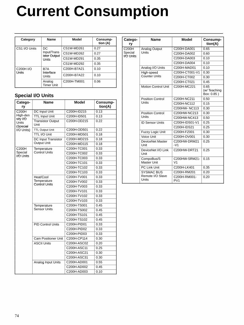
Current Consumption
74
Category Name Model Consump-tion (A)
CS1 I/O Units DCI t/T
CS1W-MD261 0.27CS /O U s CInput/Transistor Output
CS1W-MD262 0.27istor OutputUnits CS1W-MD291 0.35Units
CS1W-MD292 0.35
C200H I/OUnits
B7AInterface
C200H-B7A21 0.10Units Interface
Units C200H-B7A22 0.10
AnalogTimer Unit
C200H-TM001 0.06
Special I/O UnitsCatego-
ryName Model Consump-
tion(A)C200HHi h d
DC Input Unit C200H-ID215 0.13C 00High-density I/O
TTL Input Unit C200H-ID501 0.13sity I/OUnits(Special
Transistor OutputUnit
C200H-OD215 0.22
(S ecialI/O Units) TTL Output Unit C200H-OD501 0.22I/O Units)
TTL I/O Unit C200H-MD501 0.18
DC Input TransistorO t t U it
C200H-MD215 0.18C u a s s oOutput Unit C200H-MD115 0.18
C200HS i l
TemperatureC t l U it
C200H-TC001 0.33C 00SpecialI/O Units
e e a u eControl Units C200H-TC002 0.33
I/O UnitsC200H-TC003 0.33C200H-TC101 0.33
C200H-TC102 0.33C200H-TC103 0.33
Heat/CoolT t
C200H-TV001 0.33ea /CooTemperatureControl Units
C200H-TV002 0.33Control Units
C200H-TV003 0.33C200H-TV101 0.33
C200H-TV102 0.33C200H-TV103 0.33
TemperatureS U it
C200H-TS001 0.45e e a u eSensor Units C200H-TS002 0.45
C200H-TS101 0.45C200H-TS102 0.45
PID Control Units C200H-PID01 0.33Co o U sC200H-PID02 0.33C200H-PID03 0.33
Cam Positioner Unit C200H-CP114 0.30
ASCII Units C200H-ASC02 0.20SC U sC200H-ASC11 0.25C200H-ASC21 0.30
C200H-ASC31 0.30
Analog Input Units C200H-AD001 0.55a og u U sC200H-AD002 0.45
C200H-AD003 0.10
Catego-ry
Name Model Consump-tion(A)
C200HS i l
Analog OutputU it
C200H-DA001 0.65C 00SpecialI/O Units
a og Ou uUnits C200H-DA002 0.60
I/O UnitsC200H-DA003 0.10C200H-DA004 0.10
Analog I/O Units C200H-MAD01 0.10
High-speedC t U it
C200H-CT001-V1 0.30g s eedCounter Units C200H-CT002 0.30
C200H-CT021 0.45Motion Control Unit C200H-MC221 0.65
(w/ TeachingBox: 0.85 )
Position ControlU it
C200H-NC211 0.50os o Co oUnits C200H-NC112 0.15
C200HW- NC113 0.30
Position ControlU it
C200HW-NC213 0.30os o Co oUnits C200HW-NC413 0.50
ID Sensor Units C200H-IDS01-V1 0.25Se so U sC200H-IDS21 0.25
Fuzzy Logic Unit C200H-FZ001 0.30
Voice Unit C200H-OV001 0.30DeviceNet MasterUnit
C200HW-DRM21-V1
0.25
DeviceNet I/O LinkUnit
C200HW-DRT21 0.25
CompoBus/SMaster Unit
C200HW-SRM21-V1
0.15
PC Link Unit C200H-LK401 0.35
SYSMAC BUSR t I/O Sl
C200H-RM201 0.20S S C USRemote I/O SlaveUnits
C200H-RM001-PV1
0.20
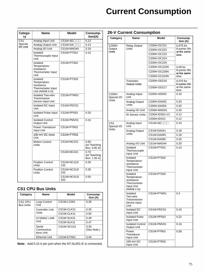
Current Consumption
75
Catego-ry
Name Model Consump-tion(A)
CS1S i l
Analog Input Unit CS1W-AD 0.13CSSpecialI/O Unit
Analog Output Unit CS1W-DA 0.13I/O Unit
Analog I/O Unit CS1W-MAD44 0.20IsolatedThermocouple InputUnit
CS1W-PTS01 0.15
IsolatedTemperature-resistanceThermometer InputUnit
CS1W-PTS02
IsolatedTemperature-resistanceThermometer InputUnit (Ni508.4 Ω)
CS1W-PTS03
Isolated Two-wireTransmissionDevice Input Unit
CS1W-PTW01
Isolated DC InputUnit
CS1W-PDC01
Isolated Pulse InputUnit
CS1W-PPS01 0.20
Isolated ControlOutput Unit
CS1W-PMV01 0.15
Power TransducerInput Unit
CS1W-PTR01
100-mV DC Input CS1W-PTR02100 mV DC In utUnit
CS1W PTR02
Motion ControlUnits
CS1W-MC221 0.60(w/ TeachingBox: 0.80 A)
CS1W-MC421 0.70(w/ TeachingBox: 1.00 A)
Position ControlUnits
CS1W-NC113/133
0.30
Position ControlUnits
CS1W-NC213/233
0.30
CS1W-NC413/433
0.50
CS1 CPU Bus UnitsCategory Name Model Consump-
tion (A)
CS1 CPUBus Units
Loop ControlUnit
CS1W-LC001 0.36
Controller LinkU it
CS1W-CLK21 0.35Co o eUnits CS1W-CLK11 0.50
SYSMAC LINKU it
CS1W-SLK21 0.48S S CUnit CS1W-SLK11 0.47
SerialCommunica-tions Unit
CS1W-SCU21 0.30 (See Note.)
Ethernet Unit CS1W-ETN01 0.40
Note: Add 0.15 A per port when the NT-AL001-E is connected.
26-V Current ConsumptionCategory Name Model Consump-
tion (A)
C200HO t t
Relay OutputU it
C200H-OC221 0.075 for8 i t ON
C 00OutputUnits
e ay Ou uUnits C200H-OC222
0 0 5 o8 points ONat the sameUnits
C200H-OC223at the sametime
C200H-OC224time
C200H-OC225
C200H-OC222N 0.09 for8 i t ONC200H-OC226N 8 points ONat the same
C200H-OC224Nat the sametime
TransistorOutput Units
C200H-OD216 0.075 for8 points ONOut ut Units
C200H-OD2178 oints ONat the sametime
C200HSpecial I/OU it
Analog IntputUnit
C200H-AD003 0.10
Units Analog OutputU it
C200H-DA003 0.20a og Ou uUnits C200H-DA004 0.25
Analog I/O Unit C200H-MAD01 0.20
ID Sensor Units C200H-IDS01-V1 0.12Se so U s
C200H-IDS21 0.12
CS1Special I/OU it
Analog InputUnit
CS1W-AD 0.10
Units Analog OutputU it
CS1W-DA041 0.18a og Ou uUnits CS1W-DA08V 0.18
CS1W-DA08C 0.25
Analog I/O Unit CS1W-MAD44 0.20
IsolatedThermocoupleInput Unit
CS1W-PTS01 0.15
IsolatedTemperature-resistanceThermometerInput Unit
CS1W-PTS02
IsolatedTemperature-resistanceThermometerInput Unit(Ni508.4 Ω)
CS1W-PTS03
IsolatedTwo-wireTransmissionDevice InputUnit
CS1W-PTW01 0.4
Isolated DCInput Unit
CS1W-PDC01 0.15
Isolated PulseInput Unit
CS1W-PPS01 0.22
Isolated ControlOutput Unit
CS1W-PMV01 0.16
PowerTransducerInput Unit
CS1W-PTR01 0.08
100-mV DCInput Unit
CS1W-PTR02
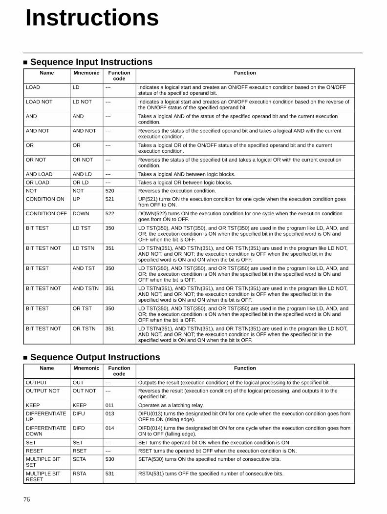
76
Sequence Input InstructionsName Mnemonic Function
codeFunction
LOAD LD --- Indicates a logical start and creates an ON/OFF execution condition based on the ON/OFFstatus of the specified operand bit.
LOAD NOT LD NOT --- Indicates a logical start and creates an ON/OFF execution condition based on the reverse ofthe ON/OFF status of the specified operand bit.
AND AND --- Takes a logical AND of the status of the specified operand bit and the current executioncondition.
AND NOT AND NOT --- Reverses the status of the specified operand bit and takes a logical AND with the currentexecution condition.
OR OR --- Takes a logical OR of the ON/OFF status of the specified operand bit and the currentexecution condition.
OR NOT OR NOT --- Reverses the status of the specified bit and takes a logical OR with the current executioncondition.
AND LOAD AND LD --- Takes a logical AND between logic blocks.
OR LOAD OR LD --- Takes a logical OR between logic blocks.
NOT NOT 520 Reverses the execution condition.
CONDITION ON UP 521 UP(521) turns ON the execution condition for one cycle when the execution condition goesfrom OFF to ON.
CONDITION OFF DOWN 522 DOWN(522) turns ON the execution condition for one cycle when the execution conditiongoes from ON to OFF.
BIT TEST LD TST 350 LD TST(350), AND TST(350), and OR TST(350) are used in the program like LD, AND, andOR; the execution condition is ON when the specified bit in the specified word is ON andOFF when the bit is OFF.
BIT TEST NOT LD TSTN 351 LD TSTN(351), AND TSTN(351), and OR TSTN(351) are used in the program like LD NOT,AND NOT, and OR NOT; the execution condition is OFF when the specified bit in thespecified word is ON and ON when the bit is OFF.
BIT TEST AND TST 350 LD TST(350), AND TST(350), and OR TST(350) are used in the program like LD, AND, andOR; the execution condition is ON when the specified bit in the specified word is ON andOFF when the bit is OFF.
BIT TEST NOT AND TSTN 351 LD TSTN(351), AND TSTN(351), and OR TSTN(351) are used in the program like LD NOT,AND NOT, and OR NOT; the execution condition is OFF when the specified bit in thespecified word is ON and ON when the bit is OFF.
BIT TEST OR TST 350 LD TST(350), AND TST(350), and OR TST(350) are used in the program like LD, AND, andOR; the execution condition is ON when the specified bit in the specified word is ON andOFF when the bit is OFF.
BIT TEST NOT OR TSTN 351 LD TSTN(351), AND TSTN(351), and OR TSTN(351) are used in the program like LD NOT,AND NOT, and OR NOT; the execution condition is OFF when the specified bit in thespecified word is ON and ON when the bit is OFF.
Sequence Output InstructionsName Mnemonic Function
codeFunction
OUTPUT OUT --- Outputs the result (execution condition) of the logical processing to the specified bit.
OUTPUT NOT OUT NOT --- Reverses the result (execution condition) of the logical processing, and outputs it to thespecified bit.
KEEP KEEP 011 Operates as a latching relay.
DIFFERENTIATEUP
DIFU 013 DIFU(013) turns the designated bit ON for one cycle when the execution condition goes fromOFF to ON (rising edge).
DIFFERENTIATEDOWN
DIFD 014 DIFD(014) turns the designated bit ON for one cycle when the execution condition goes fromON to OFF (falling edge).
SET SET --- SET turns the operand bit ON when the execution condition is ON.
RESET RSET --- RSET turns the operand bit OFF when the execution condition is ON.
MULTIPLE BITSET
SETA 530 SETA(530) turns ON the specified number of consecutive bits.
MULTIPLE BITRESET
RSTA 531 RSTA(531) turns OFF the specified number of consecutive bits.
Instructions
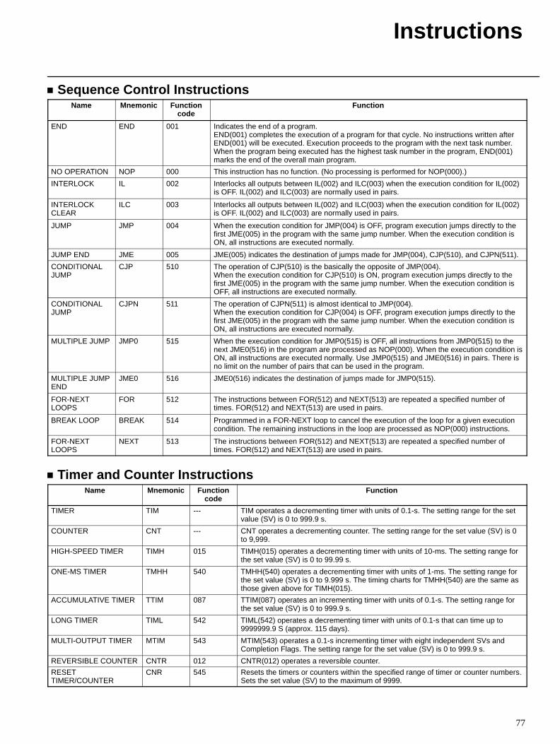
Instructions
77
Sequence Control InstructionsName Mnemonic Function
codeFunction
END END 001 Indicates the end of a program.END(001) completes the execution of a program for that cycle. No instructions written afterEND(001) will be executed. Execution proceeds to the program with the next task number.When the program being executed has the highest task number in the program, END(001)marks the end of the overall main program.
NO OPERATION NOP 000 This instruction has no function. (No processing is performed for NOP(000).)
INTERLOCK IL 002 Interlocks all outputs between IL(002) and ILC(003) when the execution condition for IL(002)is OFF. IL(002) and ILC(003) are normally used in pairs.
INTERLOCKCLEAR
ILC 003 Interlocks all outputs between IL(002) and ILC(003) when the execution condition for IL(002)is OFF. IL(002) and ILC(003) are normally used in pairs.
JUMP JMP 004 When the execution condition for JMP(004) is OFF, program execution jumps directly to thefirst JME(005) in the program with the same jump number. When the execution condition isON, all instructions are executed normally.
JUMP END JME 005 JME(005) indicates the destination of jumps made for JMP(004), CJP(510), and CJPN(511).
CONDITIONALJUMP
CJP 510 The operation of CJP(510) is the basically the opposite of JMP(004).When the execution condition for CJP(510) is ON, program execution jumps directly to thefirst JME(005) in the program with the same jump number. When the execution condition isOFF, all instructions are executed normally.
CONDITIONALJUMP
CJPN 511 The operation of CJPN(511) is almost identical to JMP(004).When the execution condition for CJP(004) is OFF, program execution jumps directly to thefirst JME(005) in the program with the same jump number. When the execution condition isON, all instructions are executed normally.
MULTIPLE JUMP JMP0 515 When the execution condition for JMP0(515) is OFF, all instructions from JMP0(515) to thenext JME0(516) in the program are processed as NOP(000). When the execution condition isON, all instructions are executed normally. Use JMP0(515) and JME0(516) in pairs. There isno limit on the number of pairs that can be used in the program.
MULTIPLE JUMPEND
JME0 516 JME0(516) indicates the destination of jumps made for JMP0(515).
FOR-NEXTLOOPS
FOR 512 The instructions between FOR(512) and NEXT(513) are repeated a specified number oftimes. FOR(512) and NEXT(513) are used in pairs.
BREAK LOOP BREAK 514 Programmed in a FOR-NEXT loop to cancel the execution of the loop for a given executioncondition. The remaining instructions in the loop are processed as NOP(000) instructions.
FOR-NEXTLOOPS
NEXT 513 The instructions between FOR(512) and NEXT(513) are repeated a specified number oftimes. FOR(512) and NEXT(513) are used in pairs.
Timer and Counter InstructionsName Mnemonic Function
codeFunction
TIMER TIM --- TIM operates a decrementing timer with units of 0.1-s. The setting range for the setvalue (SV) is 0 to 999.9 s.
COUNTER CNT --- CNT operates a decrementing counter. The setting range for the set value (SV) is 0to 9,999.
HIGH-SPEED TIMER TIMH 015 TIMH(015) operates a decrementing timer with units of 10-ms. The setting range forthe set value (SV) is 0 to 99.99 s.
ONE-MS TIMER TMHH 540 TMHH(540) operates a decrementing timer with units of 1-ms. The setting range forthe set value (SV) is 0 to 9.999 s. The timing charts for TMHH(540) are the same asthose given above for TIMH(015).
ACCUMULATIVE TIMER TTIM 087 TTIM(087) operates an incrementing timer with units of 0.1-s. The setting range forthe set value (SV) is 0 to 999.9 s.
LONG TIMER TIML 542 TIML(542) operates a decrementing timer with units of 0.1-s that can time up to9999999.9 S (approx. 115 days).
MULTI-OUTPUT TIMER MTIM 543 MTIM(543) operates a 0.1-s incrementing timer with eight independent SVs andCompletion Flags. The setting range for the set value (SV) is 0 to 999.9 s.
REVERSIBLE COUNTER CNTR 012 CNTR(012) operates a reversible counter.
RESETTIMER/COUNTER
CNR 545 Resets the timers or counters within the specified range of timer or counter numbers.Sets the set value (SV) to the maximum of 9999.
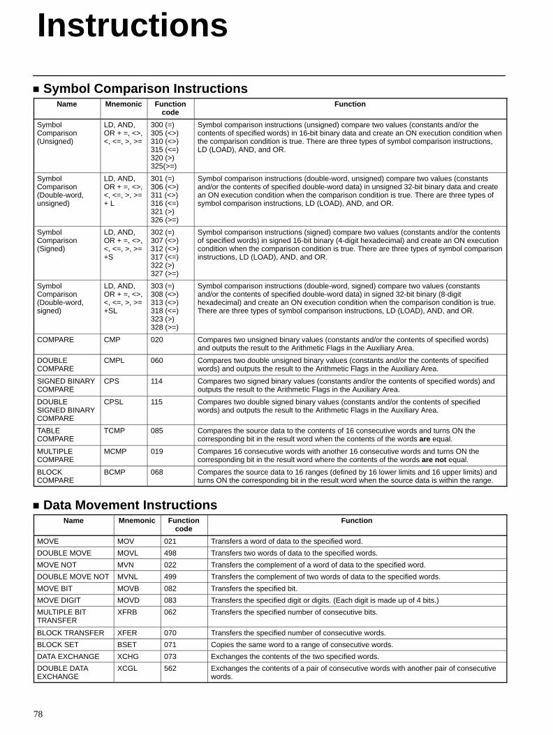
Instructions
78
Symbol Comparison InstructionsName Mnemonic Function
codeFunction
SymbolComparison(Unsigned)
LD, AND,OR + =, <>,<, <=, >, >=
300 (=)305 (<>)310 (<>)315 (<=)320 (>)325(>=)
Symbol comparison instructions (unsigned) compare two values (constants and/or thecontents of specified words) in 16-bit binary data and create an ON execution condition whenthe comparison condition is true. There are three types of symbol comparison instructions,LD (LOAD), AND, and OR.
SymbolComparison(Double-word,unsigned)
LD, AND,OR + =, <>,<, <=, >, >=+ L
301 (=)306 (<>)311 (<>)316 (<=)321 (>)326 (>=)
Symbol comparison instructions (double-word, unsigned) compare two values (constantsand/or the contents of specified double-word data) in unsigned 32-bit binary data and createan ON execution condition when the comparison condition is true. There are three types ofsymbol comparison instructions, LD (LOAD), AND, and OR.
SymbolComparison(Signed)
LD, AND,OR + =, <>,<, <=, >, >=+S
302 (=)307 (<>)312 (<>)317 (<=)322 (>)327 (>=)
Symbol comparison instructions (signed) compare two values (constants and/or the contentsof specified words) in signed 16-bit binary (4-digit hexadecimal) and create an ON executioncondition when the comparison condition is true. There are three types of symbol comparisoninstructions, LD (LOAD), AND, and OR.
SymbolComparison(Double-word,signed)
LD, AND,OR + =, <>,<, <=, >, >=+SL
303 (=)308 (<>)313 (<>)318 (<=)323 (>)328 (>=)
Symbol comparison instructions (double-word, signed) compare two values (constantsand/or the contents of specified double-word data) in signed 32-bit binary (8-digithexadecimal) and create an ON execution condition when the comparison condition is true.There are three types of symbol comparison instructions, LD (LOAD), AND, and OR.
COMPARE CMP 020 Compares two unsigned binary values (constants and/or the contents of specified words)and outputs the result to the Arithmetic Flags in the Auxiliary Area.
DOUBLECOMPARE
CMPL 060 Compares two double unsigned binary values (constants and/or the contents of specifiedwords) and outputs the result to the Arithmetic Flags in the Auxiliary Area.
SIGNED BINARYCOMPARE
CPS 114 Compares two signed binary values (constants and/or the contents of specified words) andoutputs the result to the Arithmetic Flags in the Auxiliary Area.
DOUBLESIGNED BINARYCOMPARE
CPSL 115 Compares two double signed binary values (constants and/or the contents of specifiedwords) and outputs the result to the Arithmetic Flags in the Auxiliary Area.
TABLECOMPARE
TCMP 085 Compares the source data to the contents of 16 consecutive words and turns ON thecorresponding bit in the result word when the contents of the words are equal.
MULTIPLECOMPARE
MCMP 019 Compares 16 consecutive words with another 16 consecutive words and turns ON thecorresponding bit in the result word where the contents of the words are not equal.
BLOCKCOMPARE
BCMP 068 Compares the source data to 16 ranges (defined by 16 lower limits and 16 upper limits) andturns ON the corresponding bit in the result word when the source data is within the range.
Data Movement InstructionsName Mnemonic Function
codeFunction
MOVE MOV 021 Transfers a word of data to the specified word.
DOUBLE MOVE MOVL 498 Transfers two words of data to the specified words.
MOVE NOT MVN 022 Transfers the complement of a word of data to the specified word.
DOUBLE MOVE NOT MVNL 499 Transfers the complement of two words of data to the specified words.
MOVE BIT MOVB 082 Transfers the specified bit.
MOVE DIGIT MOVD 083 Transfers the specified digit or digits. (Each digit is made up of 4 bits.)
MULTIPLE BITTRANSFER
XFRB 062 Transfers the specified number of consecutive bits.
BLOCK TRANSFER XFER 070 Transfers the specified number of consecutive words.
BLOCK SET BSET 071 Copies the same word to a range of consecutive words.
DATA EXCHANGE XCHG 073 Exchanges the contents of the two specified words.
DOUBLE DATAEXCHANGE
XCGL 562 Exchanges the contents of a pair of consecutive words with another pair of consecutivewords.
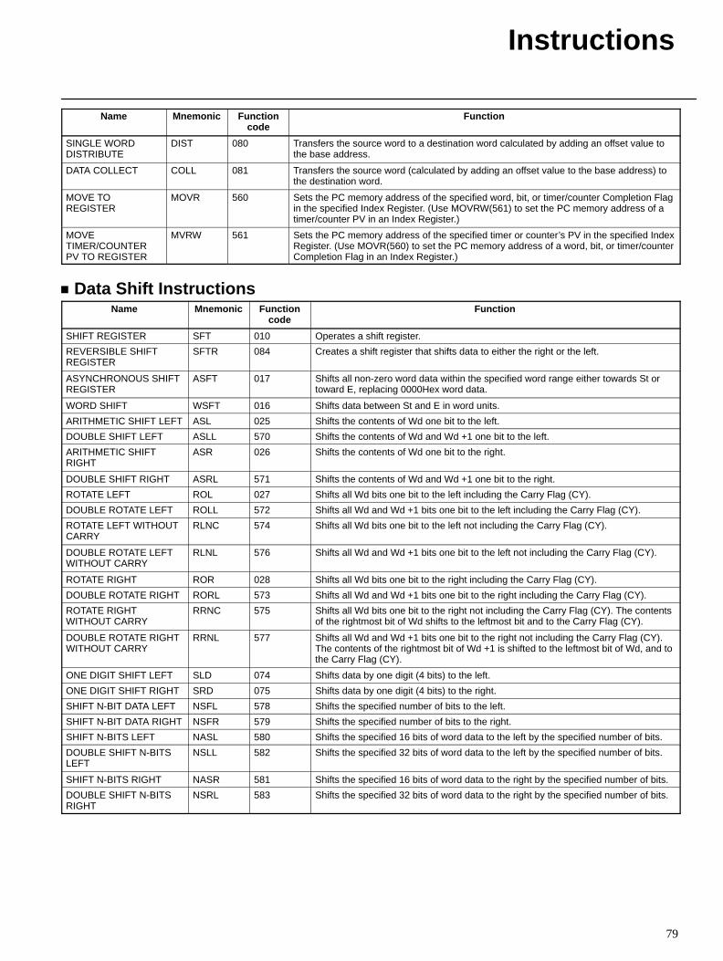
Instructions
79
Name FunctionFunctioncode
Mnemonic
SINGLE WORDDISTRIBUTE
DIST 080 Transfers the source word to a destination word calculated by adding an offset value tothe base address.
DATA COLLECT COLL 081 Transfers the source word (calculated by adding an offset value to the base address) tothe destination word.
MOVE TOREGISTER
MOVR 560 Sets the PC memory address of the specified word, bit, or timer/counter Completion Flagin the specified Index Register. (Use MOVRW(561) to set the PC memory address of atimer/counter PV in an Index Register.)
MOVETIMER/COUNTERPV TO REGISTER
MVRW 561 Sets the PC memory address of the specified timer or counter’s PV in the specified IndexRegister. (Use MOVR(560) to set the PC memory address of a word, bit, or timer/counterCompletion Flag in an Index Register.)
Data Shift InstructionsName Mnemonic Function
codeFunction
SHIFT REGISTER SFT 010 Operates a shift register.
REVERSIBLE SHIFTREGISTER
SFTR 084 Creates a shift register that shifts data to either the right or the left.
ASYNCHRONOUS SHIFTREGISTER
ASFT 017 Shifts all non-zero word data within the specified word range either towards St ortoward E, replacing 0000Hex word data.
WORD SHIFT WSFT 016 Shifts data between St and E in word units.
ARITHMETIC SHIFT LEFT ASL 025 Shifts the contents of Wd one bit to the left.
DOUBLE SHIFT LEFT ASLL 570 Shifts the contents of Wd and Wd +1 one bit to the left.
ARITHMETIC SHIFTRIGHT
ASR 026 Shifts the contents of Wd one bit to the right.
DOUBLE SHIFT RIGHT ASRL 571 Shifts the contents of Wd and Wd +1 one bit to the right.
ROTATE LEFT ROL 027 Shifts all Wd bits one bit to the left including the Carry Flag (CY).
DOUBLE ROTATE LEFT ROLL 572 Shifts all Wd and Wd +1 bits one bit to the left including the Carry Flag (CY).
ROTATE LEFT WITHOUTCARRY
RLNC 574 Shifts all Wd bits one bit to the left not including the Carry Flag (CY).
DOUBLE ROTATE LEFTWITHOUT CARRY
RLNL 576 Shifts all Wd and Wd +1 bits one bit to the left not including the Carry Flag (CY).
ROTATE RIGHT ROR 028 Shifts all Wd bits one bit to the right including the Carry Flag (CY).
DOUBLE ROTATE RIGHT RORL 573 Shifts all Wd and Wd +1 bits one bit to the right including the Carry Flag (CY).
ROTATE RIGHTWITHOUT CARRY
RRNC 575 Shifts all Wd bits one bit to the right not including the Carry Flag (CY). The contentsof the rightmost bit of Wd shifts to the leftmost bit and to the Carry Flag (CY).
DOUBLE ROTATE RIGHTWITHOUT CARRY
RRNL 577 Shifts all Wd and Wd +1 bits one bit to the right not including the Carry Flag (CY).The contents of the rightmost bit of Wd +1 is shifted to the leftmost bit of Wd, and tothe Carry Flag (CY).
ONE DIGIT SHIFT LEFT SLD 074 Shifts data by one digit (4 bits) to the left.
ONE DIGIT SHIFT RIGHT SRD 075 Shifts data by one digit (4 bits) to the right.
SHIFT N-BIT DATA LEFT NSFL 578 Shifts the specified number of bits to the left.
SHIFT N-BIT DATA RIGHT NSFR 579 Shifts the specified number of bits to the right.
SHIFT N-BITS LEFT NASL 580 Shifts the specified 16 bits of word data to the left by the specified number of bits.
DOUBLE SHIFT N-BITSLEFT
NSLL 582 Shifts the specified 32 bits of word data to the left by the specified number of bits.
SHIFT N-BITS RIGHT NASR 581 Shifts the specified 16 bits of word data to the right by the specified number of bits.
DOUBLE SHIFT N-BITSRIGHT
NSRL 583 Shifts the specified 32 bits of word data to the right by the specified number of bits.
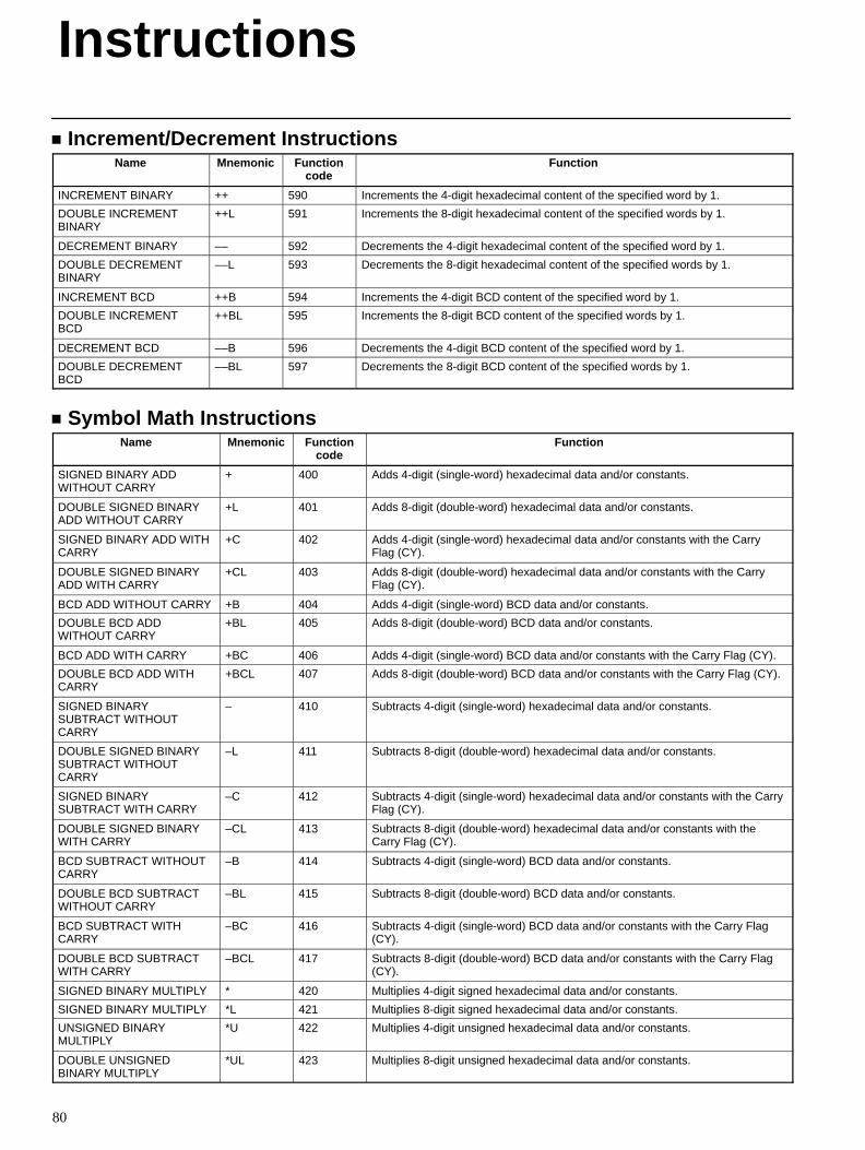
Instructions
80
Increment/Decrement InstructionsName Mnemonic Function
codeFunction
INCREMENT BINARY ++ 590 Increments the 4-digit hexadecimal content of the specified word by 1.
DOUBLE INCREMENTBINARY
++L 591 Increments the 8-digit hexadecimal content of the specified words by 1.
DECREMENT BINARY –– 592 Decrements the 4-digit hexadecimal content of the specified word by 1.
DOUBLE DECREMENTBINARY
––L 593 Decrements the 8-digit hexadecimal content of the specified words by 1.
INCREMENT BCD ++B 594 Increments the 4-digit BCD content of the specified word by 1.
DOUBLE INCREMENTBCD
++BL 595 Increments the 8-digit BCD content of the specified words by 1.
DECREMENT BCD ––B 596 Decrements the 4-digit BCD content of the specified word by 1.
DOUBLE DECREMENTBCD
––BL 597 Decrements the 8-digit BCD content of the specified words by 1.
Symbol Math InstructionsName Mnemonic Function
codeFunction
SIGNED BINARY ADDWITHOUT CARRY
+ 400 Adds 4-digit (single-word) hexadecimal data and/or constants.
DOUBLE SIGNED BINARYADD WITHOUT CARRY
+L 401 Adds 8-digit (double-word) hexadecimal data and/or constants.
SIGNED BINARY ADD WITHCARRY
+C 402 Adds 4-digit (single-word) hexadecimal data and/or constants with the CarryFlag (CY).
DOUBLE SIGNED BINARYADD WITH CARRY
+CL 403 Adds 8-digit (double-word) hexadecimal data and/or constants with the CarryFlag (CY).
BCD ADD WITHOUT CARRY +B 404 Adds 4-digit (single-word) BCD data and/or constants.
DOUBLE BCD ADDWITHOUT CARRY
+BL 405 Adds 8-digit (double-word) BCD data and/or constants.
BCD ADD WITH CARRY +BC 406 Adds 4-digit (single-word) BCD data and/or constants with the Carry Flag (CY).
DOUBLE BCD ADD WITHCARRY
+BCL 407 Adds 8-digit (double-word) BCD data and/or constants with the Carry Flag (CY).
SIGNED BINARYSUBTRACT WITHOUTCARRY
– 410 Subtracts 4-digit (single-word) hexadecimal data and/or constants.
DOUBLE SIGNED BINARYSUBTRACT WITHOUTCARRY
–L 411 Subtracts 8-digit (double-word) hexadecimal data and/or constants.
SIGNED BINARYSUBTRACT WITH CARRY
–C 412 Subtracts 4-digit (single-word) hexadecimal data and/or constants with the CarryFlag (CY).
DOUBLE SIGNED BINARYWITH CARRY
–CL 413 Subtracts 8-digit (double-word) hexadecimal data and/or constants with theCarry Flag (CY).
BCD SUBTRACT WITHOUTCARRY
–B 414 Subtracts 4-digit (single-word) BCD data and/or constants.
DOUBLE BCD SUBTRACTWITHOUT CARRY
–BL 415 Subtracts 8-digit (double-word) BCD data and/or constants.
BCD SUBTRACT WITHCARRY
–BC 416 Subtracts 4-digit (single-word) BCD data and/or constants with the Carry Flag(CY).
DOUBLE BCD SUBTRACTWITH CARRY
–BCL 417 Subtracts 8-digit (double-word) BCD data and/or constants with the Carry Flag(CY).
SIGNED BINARY MULTIPLY * 420 Multiplies 4-digit signed hexadecimal data and/or constants.
SIGNED BINARY MULTIPLY *L 421 Multiplies 8-digit signed hexadecimal data and/or constants.
UNSIGNED BINARYMULTIPLY
*U 422 Multiplies 4-digit unsigned hexadecimal data and/or constants.
DOUBLE UNSIGNEDBINARY MULTIPLY
*UL 423 Multiplies 8-digit unsigned hexadecimal data and/or constants.
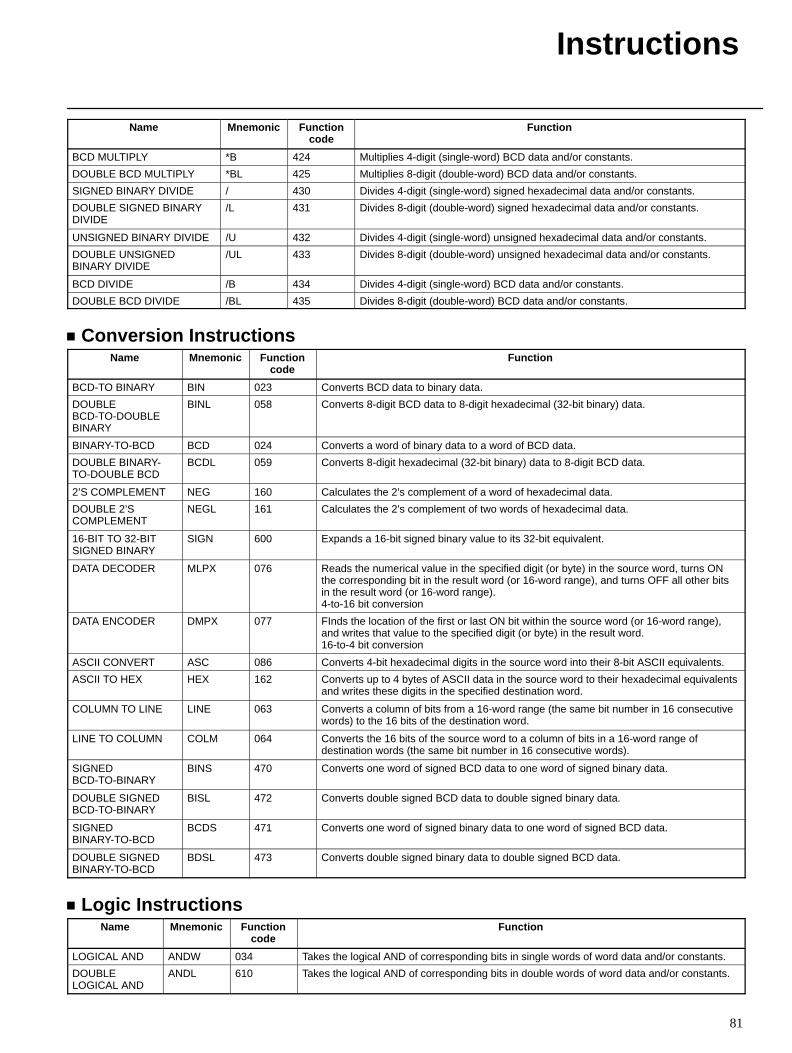
Instructions
81
Name FunctionFunctioncode
Mnemonic
BCD MULTIPLY *B 424 Multiplies 4-digit (single-word) BCD data and/or constants.
DOUBLE BCD MULTIPLY *BL 425 Multiplies 8-digit (double-word) BCD data and/or constants.
SIGNED BINARY DIVIDE / 430 Divides 4-digit (single-word) signed hexadecimal data and/or constants.
DOUBLE SIGNED BINARYDIVIDE
/L 431 Divides 8-digit (double-word) signed hexadecimal data and/or constants.
UNSIGNED BINARY DIVIDE /U 432 Divides 4-digit (single-word) unsigned hexadecimal data and/or constants.
DOUBLE UNSIGNEDBINARY DIVIDE
/UL 433 Divides 8-digit (double-word) unsigned hexadecimal data and/or constants.
BCD DIVIDE /B 434 Divides 4-digit (single-word) BCD data and/or constants.
DOUBLE BCD DIVIDE /BL 435 Divides 8-digit (double-word) BCD data and/or constants.
Conversion InstructionsName Mnemonic Function
codeFunction
BCD-TO BINARY BIN 023 Converts BCD data to binary data.
DOUBLEBCD-TO-DOUBLEBINARY
BINL 058 Converts 8-digit BCD data to 8-digit hexadecimal (32-bit binary) data.
BINARY-TO-BCD BCD 024 Converts a word of binary data to a word of BCD data.
DOUBLE BINARY-TO-DOUBLE BCD
BCDL 059 Converts 8-digit hexadecimal (32-bit binary) data to 8-digit BCD data.
2’S COMPLEMENT NEG 160 Calculates the 2’s complement of a word of hexadecimal data.
DOUBLE 2’SCOMPLEMENT
NEGL 161 Calculates the 2’s complement of two words of hexadecimal data.
16-BIT TO 32-BITSIGNED BINARY
SIGN 600 Expands a 16-bit signed binary value to its 32-bit equivalent.
DATA DECODER MLPX 076 Reads the numerical value in the specified digit (or byte) in the source word, turns ONthe corresponding bit in the result word (or 16-word range), and turns OFF all other bitsin the result word (or 16-word range).4-to-16 bit conversion
DATA ENCODER DMPX 077 FInds the location of the first or last ON bit within the source word (or 16-word range),and writes that value to the specified digit (or byte) in the result word.16-to-4 bit conversion
ASCII CONVERT ASC 086 Converts 4-bit hexadecimal digits in the source word into their 8-bit ASCII equivalents.
ASCII TO HEX HEX 162 Converts up to 4 bytes of ASCII data in the source word to their hexadecimal equivalentsand writes these digits in the specified destination word.
COLUMN TO LINE LINE 063 Converts a column of bits from a 16-word range (the same bit number in 16 consecutivewords) to the 16 bits of the destination word.
LINE TO COLUMN COLM 064 Converts the 16 bits of the source word to a column of bits in a 16-word range ofdestination words (the same bit number in 16 consecutive words).
SIGNEDBCD-TO-BINARY
BINS 470 Converts one word of signed BCD data to one word of signed binary data.
DOUBLE SIGNEDBCD-TO-BINARY
BISL 472 Converts double signed BCD data to double signed binary data.
SIGNEDBINARY-TO-BCD
BCDS 471 Converts one word of signed binary data to one word of signed BCD data.
DOUBLE SIGNEDBINARY-TO-BCD
BDSL 473 Converts double signed binary data to double signed BCD data.
Logic InstructionsName Mnemonic Function
codeFunction
LOGICAL AND ANDW 034 Takes the logical AND of corresponding bits in single words of word data and/or constants.
DOUBLELOGICAL AND
ANDL 610 Takes the logical AND of corresponding bits in double words of word data and/or constants.
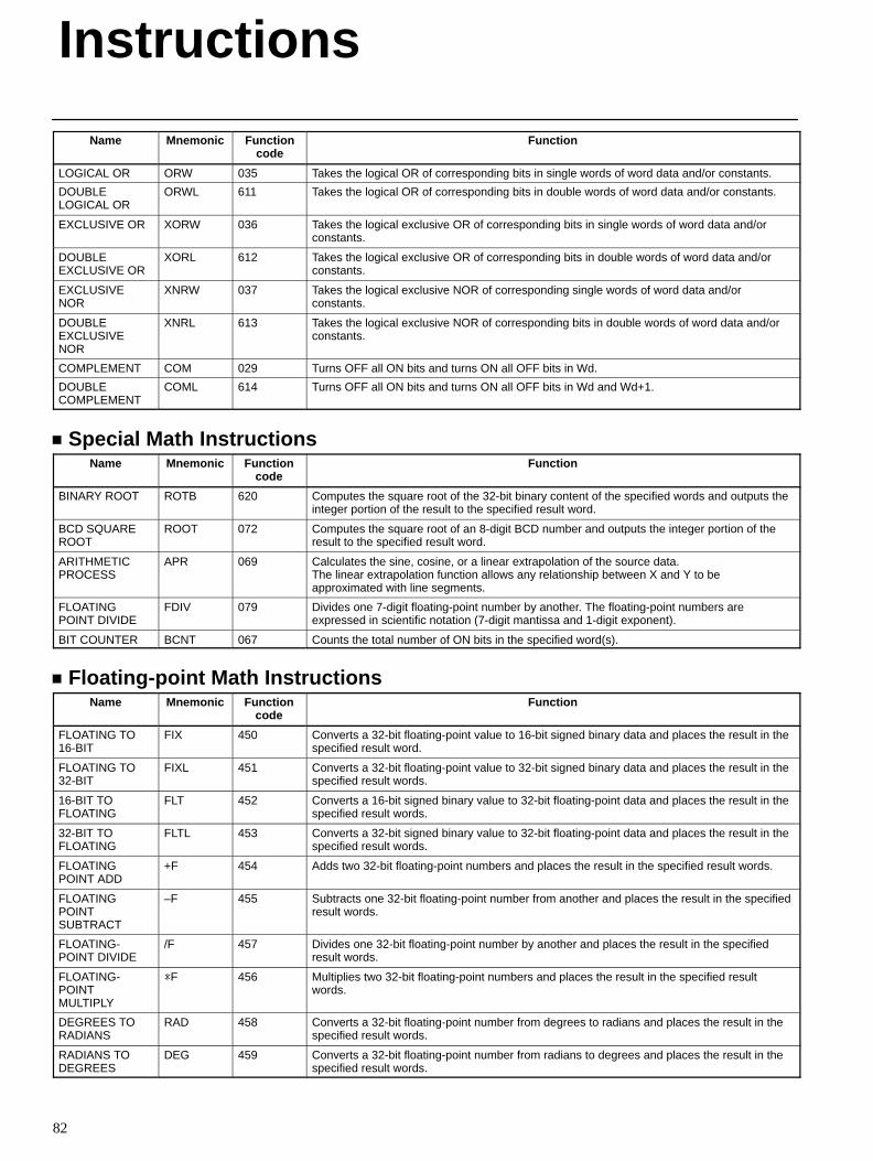
Instructions
82
Name FunctionFunctioncode
Mnemonic
LOGICAL OR ORW 035 Takes the logical OR of corresponding bits in single words of word data and/or constants.
DOUBLELOGICAL OR
ORWL 611 Takes the logical OR of corresponding bits in double words of word data and/or constants.
EXCLUSIVE OR XORW 036 Takes the logical exclusive OR of corresponding bits in single words of word data and/orconstants.
DOUBLEEXCLUSIVE OR
XORL 612 Takes the logical exclusive OR of corresponding bits in double words of word data and/orconstants.
EXCLUSIVENOR
XNRW 037 Takes the logical exclusive NOR of corresponding single words of word data and/orconstants.
DOUBLEEXCLUSIVENOR
XNRL 613 Takes the logical exclusive NOR of corresponding bits in double words of word data and/orconstants.
COMPLEMENT COM 029 Turns OFF all ON bits and turns ON all OFF bits in Wd.
DOUBLECOMPLEMENT
COML 614 Turns OFF all ON bits and turns ON all OFF bits in Wd and Wd+1.
Special Math InstructionsName Mnemonic Function
codeFunction
BINARY ROOT ROTB 620 Computes the square root of the 32-bit binary content of the specified words and outputs theinteger portion of the result to the specified result word.
BCD SQUAREROOT
ROOT 072 Computes the square root of an 8-digit BCD number and outputs the integer portion of theresult to the specified result word.
ARITHMETICPROCESS
APR 069 Calculates the sine, cosine, or a linear extrapolation of the source data.The linear extrapolation function allows any relationship between X and Y to beapproximated with line segments.
FLOATINGPOINT DIVIDE
FDIV 079 Divides one 7-digit floating-point number by another. The floating-point numbers areexpressed in scientific notation (7-digit mantissa and 1-digit exponent).
BIT COUNTER BCNT 067 Counts the total number of ON bits in the specified word(s).
Floating-point Math InstructionsName Mnemonic Function
codeFunction
FLOATING TO16-BIT
FIX 450 Converts a 32-bit floating-point value to 16-bit signed binary data and places the result in thespecified result word.
FLOATING TO32-BIT
FIXL 451 Converts a 32-bit floating-point value to 32-bit signed binary data and places the result in thespecified result words.
16-BIT TOFLOATING
FLT 452 Converts a 16-bit signed binary value to 32-bit floating-point data and places the result in thespecified result words.
32-BIT TOFLOATING
FLTL 453 Converts a 32-bit signed binary value to 32-bit floating-point data and places the result in thespecified result words.
FLOATINGPOINT ADD
+F 454 Adds two 32-bit floating-point numbers and places the result in the specified result words.
FLOATINGPOINTSUBTRACT
–F 455 Subtracts one 32-bit floating-point number from another and places the result in the specifiedresult words.
FLOATING-POINT DIVIDE
/F 457 Divides one 32-bit floating-point number by another and places the result in the specifiedresult words.
FLOATING-POINTMULTIPLY
*F 456 Multiplies two 32-bit floating-point numbers and places the result in the specified resultwords.
DEGREES TORADIANS
RAD 458 Converts a 32-bit floating-point number from degrees to radians and places the result in thespecified result words.
RADIANS TODEGREES
DEG 459 Converts a 32-bit floating-point number from radians to degrees and places the result in thespecified result words.
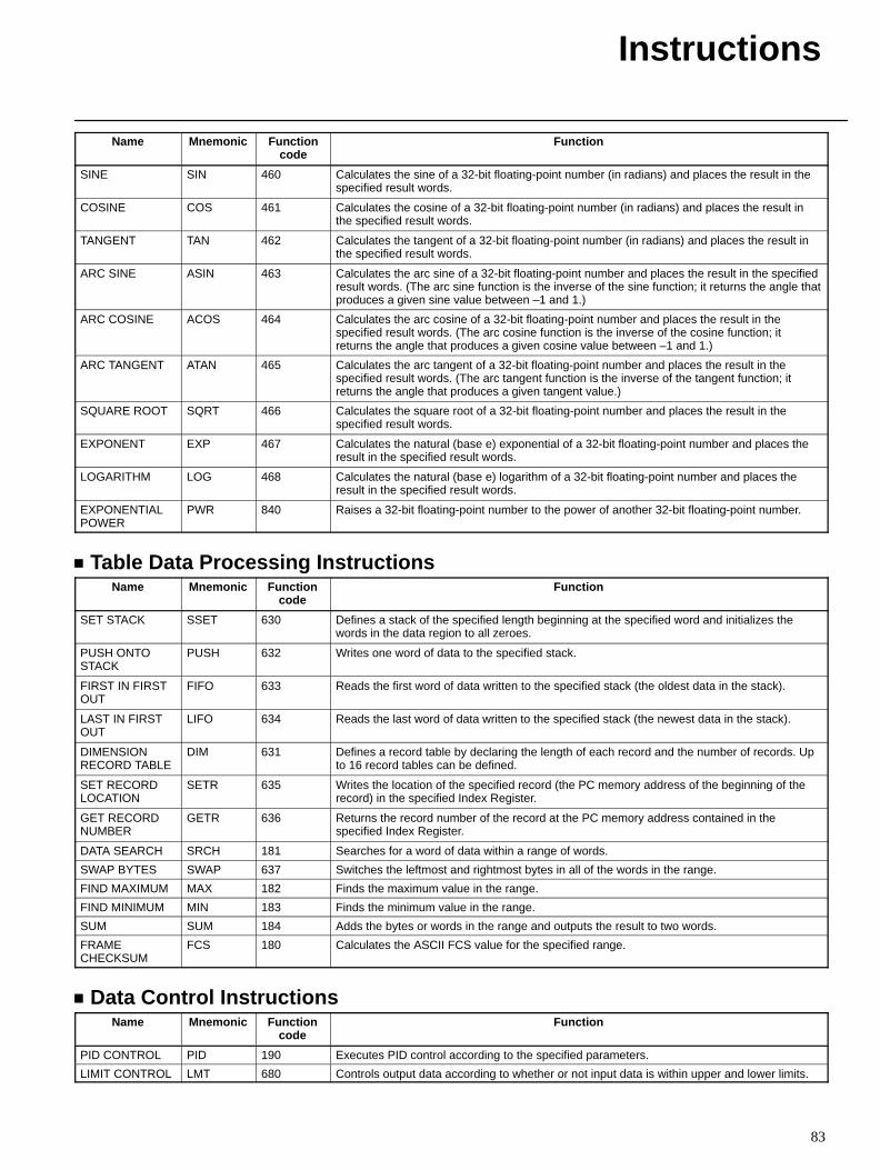
Instructions
83
Name FunctionFunctioncode
Mnemonic
SINE SIN 460 Calculates the sine of a 32-bit floating-point number (in radians) and places the result in thespecified result words.
COSINE COS 461 Calculates the cosine of a 32-bit floating-point number (in radians) and places the result inthe specified result words.
TANGENT TAN 462 Calculates the tangent of a 32-bit floating-point number (in radians) and places the result inthe specified result words.
ARC SINE ASIN 463 Calculates the arc sine of a 32-bit floating-point number and places the result in the specifiedresult words. (The arc sine function is the inverse of the sine function; it returns the angle thatproduces a given sine value between –1 and 1.)
ARC COSINE ACOS 464 Calculates the arc cosine of a 32-bit floating-point number and places the result in thespecified result words. (The arc cosine function is the inverse of the cosine function; itreturns the angle that produces a given cosine value between –1 and 1.)
ARC TANGENT ATAN 465 Calculates the arc tangent of a 32-bit floating-point number and places the result in thespecified result words. (The arc tangent function is the inverse of the tangent function; itreturns the angle that produces a given tangent value.)
SQUARE ROOT SQRT 466 Calculates the square root of a 32-bit floating-point number and places the result in thespecified result words.
EXPONENT EXP 467 Calculates the natural (base e) exponential of a 32-bit floating-point number and places theresult in the specified result words.
LOGARITHM LOG 468 Calculates the natural (base e) logarithm of a 32-bit floating-point number and places theresult in the specified result words.
EXPONENTIALPOWER
PWR 840 Raises a 32-bit floating-point number to the power of another 32-bit floating-point number.
Table Data Processing InstructionsName Mnemonic Function
codeFunction
SET STACK SSET 630 Defines a stack of the specified length beginning at the specified word and initializes thewords in the data region to all zeroes.
PUSH ONTOSTACK
PUSH 632 Writes one word of data to the specified stack.
FIRST IN FIRSTOUT
FIFO 633 Reads the first word of data written to the specified stack (the oldest data in the stack).
LAST IN FIRSTOUT
LIFO 634 Reads the last word of data written to the specified stack (the newest data in the stack).
DIMENSIONRECORD TABLE
DIM 631 Defines a record table by declaring the length of each record and the number of records. Upto 16 record tables can be defined.
SET RECORDLOCATION
SETR 635 Writes the location of the specified record (the PC memory address of the beginning of therecord) in the specified Index Register.
GET RECORDNUMBER
GETR 636 Returns the record number of the record at the PC memory address contained in thespecified Index Register.
DATA SEARCH SRCH 181 Searches for a word of data within a range of words.
SWAP BYTES SWAP 637 Switches the leftmost and rightmost bytes in all of the words in the range.
FIND MAXIMUM MAX 182 Finds the maximum value in the range.
FIND MINIMUM MIN 183 Finds the minimum value in the range.
SUM SUM 184 Adds the bytes or words in the range and outputs the result to two words.
FRAMECHECKSUM
FCS 180 Calculates the ASCII FCS value for the specified range.
Data Control InstructionsName Mnemonic Function
codeFunction
PID CONTROL PID 190 Executes PID control according to the specified parameters.
LIMIT CONTROL LMT 680 Controls output data according to whether or not input data is within upper and lower limits.
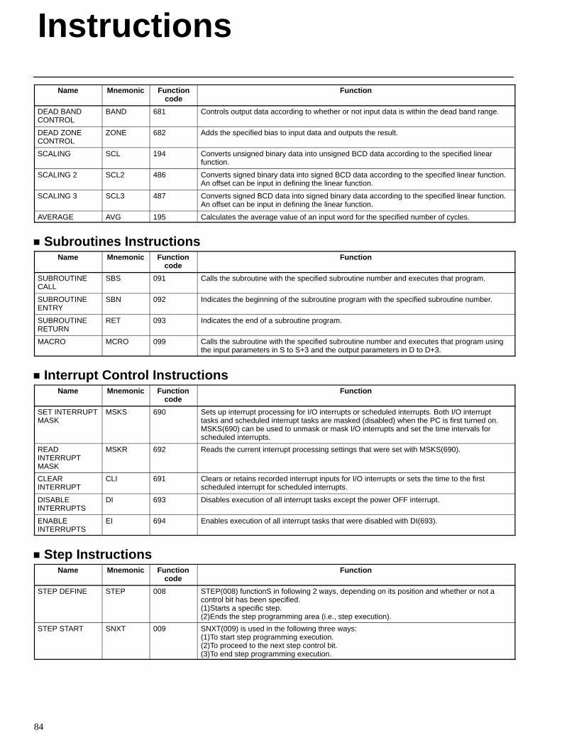
Instructions
84
Name FunctionFunctioncode
Mnemonic
DEAD BANDCONTROL
BAND 681 Controls output data according to whether or not input data is within the dead band range.
DEAD ZONECONTROL
ZONE 682 Adds the specified bias to input data and outputs the result.
SCALING SCL 194 Converts unsigned binary data into unsigned BCD data according to the specified linearfunction.
SCALING 2 SCL2 486 Converts signed binary data into signed BCD data according to the specified linear function.An offset can be input in defining the linear function.
SCALING 3 SCL3 487 Converts signed BCD data into signed binary data according to the specified linear function.An offset can be input in defining the linear function.
AVERAGE AVG 195 Calculates the average value of an input word for the specified number of cycles.
Subroutines InstructionsName Mnemonic Function
codeFunction
SUBROUTINECALL
SBS 091 Calls the subroutine with the specified subroutine number and executes that program.
SUBROUTINEENTRY
SBN 092 Indicates the beginning of the subroutine program with the specified subroutine number.
SUBROUTINERETURN
RET 093 Indicates the end of a subroutine program.
MACRO MCRO 099 Calls the subroutine with the specified subroutine number and executes that program usingthe input parameters in S to S+3 and the output parameters in D to D+3.
Interrupt Control InstructionsName Mnemonic Function
codeFunction
SET INTERRUPTMASK
MSKS 690 Sets up interrupt processing for I/O interrupts or scheduled interrupts. Both I/O interrupttasks and scheduled interrupt tasks are masked (disabled) when the PC is first turned on.MSKS(690) can be used to unmask or mask I/O interrupts and set the time intervals forscheduled interrupts.
READINTERRUPTMASK
MSKR 692 Reads the current interrupt processing settings that were set with MSKS(690).
CLEARINTERRUPT
CLI 691 Clears or retains recorded interrupt inputs for I/O interrupts or sets the time to the firstscheduled interrupt for scheduled interrupts.
DISABLEINTERRUPTS
DI 693 Disables execution of all interrupt tasks except the power OFF interrupt.
ENABLEINTERRUPTS
EI 694 Enables execution of all interrupt tasks that were disabled with DI(693).
Step InstructionsName Mnemonic Function
codeFunction
STEP DEFINE STEP 008 STEP(008) functionS in following 2 ways, depending on its position and whether or not acontrol bit has been specified.(1)Starts a specific step.(2)Ends the step programming area (i.e., step execution).
STEP START SNXT 009 SNXT(009) is used in the following three ways:(1)To start step programming execution.(2)To proceed to the next step control bit.(3)To end step programming execution.
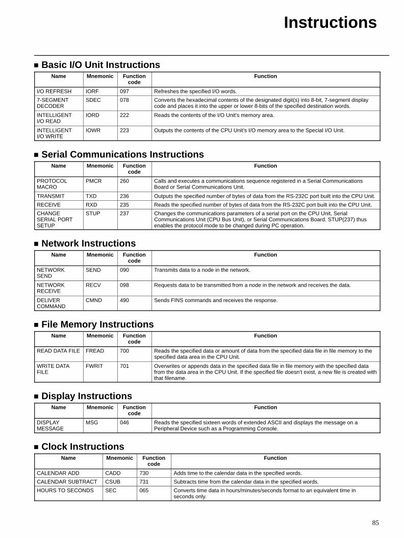
Instructions
85
Basic I/O Unit InstructionsName Mnemonic Function
codeFunction
I/O REFRESH IORF 097 Refreshes the specified I/O words.
7-SEGMENTDECODER
SDEC 078 Converts the hexadecimal contents of the designated digit(s) into 8-bit, 7-segment displaycode and places it into the upper or lower 8-bits of the specified destination words.
INTELLIGENTI/O READ
IORD 222 Reads the contents of the I/O Unit’s memory area.
INTELLIGENTI/O WRITE
IOWR 223 Outputs the contents of the CPU Unit’s I/O memory area to the Special I/O Unit.
Serial Communications InstructionsName Mnemonic Function
codeFunction
PROTOCOLMACRO
PMCR 260 Calls and executes a communications sequence registered in a Serial CommunicationsBoard or Serial Communications Unit.
TRANSMIT TXD 236 Outputs the specified number of bytes of data from the RS-232C port built into the CPU Unit.
RECEIVE RXD 235 Reads the specified number of bytes of data from the RS-232C port built into the CPU Unit.
CHANGESERIAL PORTSETUP
STUP 237 Changes the communications parameters of a serial port on the CPU Unit, SerialCommunications Unit (CPU Bus Unit), or Serial Communications Board. STUP(237) thusenables the protocol mode to be changed during PC operation.
Network InstructionsName Mnemonic Function
codeFunction
NETWORKSEND
SEND 090 Transmits data to a node in the network.
NETWORKRECEIVE
RECV 098 Requests data to be transmitted from a node in the network and receives the data.
DELIVERCOMMAND
CMND 490 Sends FINS commands and receives the response.
File Memory InstructionsName Mnemonic Function
codeFunction
READ DATA FILE FREAD 700 Reads the specified data or amount of data from the specified data file in file memory to thespecified data area in the CPU Unit.
WRITE DATAFILE
FWRIT 701 Overwrites or appends data in the specified data file in file memory with the specified datafrom the data area in the CPU Unit. If the specified file doesn’t exist, a new file is created withthat filename.
Display InstructionsName Mnemonic Function
codeFunction
DISPLAYMESSAGE
MSG 046 Reads the specified sixteen words of extended ASCII and displays the message on aPeripheral Device such as a Programming Console.
Clock InstructionsName Mnemonic Function
codeFunction
CALENDAR ADD CADD 730 Adds time to the calendar data in the specified words.
CALENDAR SUBTRACT CSUB 731 Subtracts time from the calendar data in the specified words.
HOURS TO SECONDS SEC 065 Converts time data in hours/minutes/seconds format to an equivalent time inseconds only.
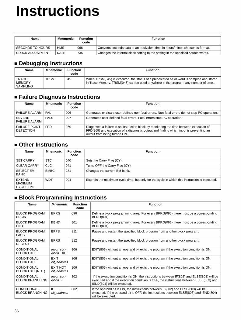
Instructions
86
Name FunctionFunctioncode
Mnemonic
SECONDS TO HOURS HMS 066 Converts seconds data to an equivalent time in hours/minutes/seconds format.
CLOCK ADJUSTMENT DATE 735 Changes the internal clock setting to the setting in the specified source words.
Debugging InstructionsName Mnemonic Function
codeFunction
TRACEMEMORYSAMPLING
TRSM 045 When TRSM(045) is executed, the status of a preselected bit or word is sampled and storedin Trace Memory. TRSM(045) can be used anywhere in the program, any number of times.
Failure Diagnosis InstructionsName Mnemonic Function
codeFunction
FAILURE ALARM FAL 006 Generates or clears user-defined non-fatal errors. Non-fatal errors do not stop PC operation.
SEVEREFAILURE ALARM
FALS 007 Generates user-defined fatal errors. Fatal errors stop PC operation.
FAILURE POINTDETECTION
FPD 269 Diagnoses a failure in an instruction block by monitoring the time between execution ofFPD(269) and execution of a diagnostic output and finding which input is preventing anoutput from being turned ON.
Other InstructionsName Mnemonic Function
codeFunction
SET CARRY STC 040 Sets the Carry Flag (CY).
CLEAR CARRY CLC 041 Turns OFF the Carry Flag (CY).
SELECT EMBANK
EMBC 281 Changes the current EM bank.
EXTENDMAXIMUMCYCLE TIME
WDT 094 Extends the maximum cycle time, but only for the cycle in which this instruction is executed.
Block Programming InstructionsName Mnemonic Function
codeFunction
BLOCK PROGRAMBEGIN
BPRG 096 Define a block programming area. For every BPRG(096) there must be a correspondingBEND(801).
BLOCK PROGRAMEND
BEND 801 Define a block programming area. For every BPRG(096) there must be a correspondingBEND(801).
BLOCK PROGRAMPAUSE
BPPS 811 Pause and restart the specified block program from another block program.
BLOCK PROGRAMRESTART
BPRS 812 Pause and restart the specified block program from another block program.
CONDITIONALBLOCK EXIT
input_con-dition EXIT
806 EXIT(806) without an operand bit exits the program if the execution condition is ON.
CONDITIONALBLOCK EXIT
EXITbit_address
806 EXIT(806) without an operand bit exits the program if the execution condition is ON.
CONDITIONALBLOCK EXIT (NOT)
EXIT NOTbit_address
806 EXIT(806) without an operand bit exits the program if the execution condition is ON.
CONDITIONALBLOCK BRANCHING
input_con-dition IF
802 If the execution condition is ON, the instructions between IF(802) and ELSE(803) will beexecuted and if the execution condition is OFF, the instructions between ELSE(803) andIEND(804) will be executed.
CONDITIONALBLOCK BRANCHING
IFbit_address
802 If the operand bit is ON, the instructions between IF(802) and ELSE(803) will beexecuted. If the operand bit is OFF, the instructions between ELSE(803) and IEND(804)will be executed.
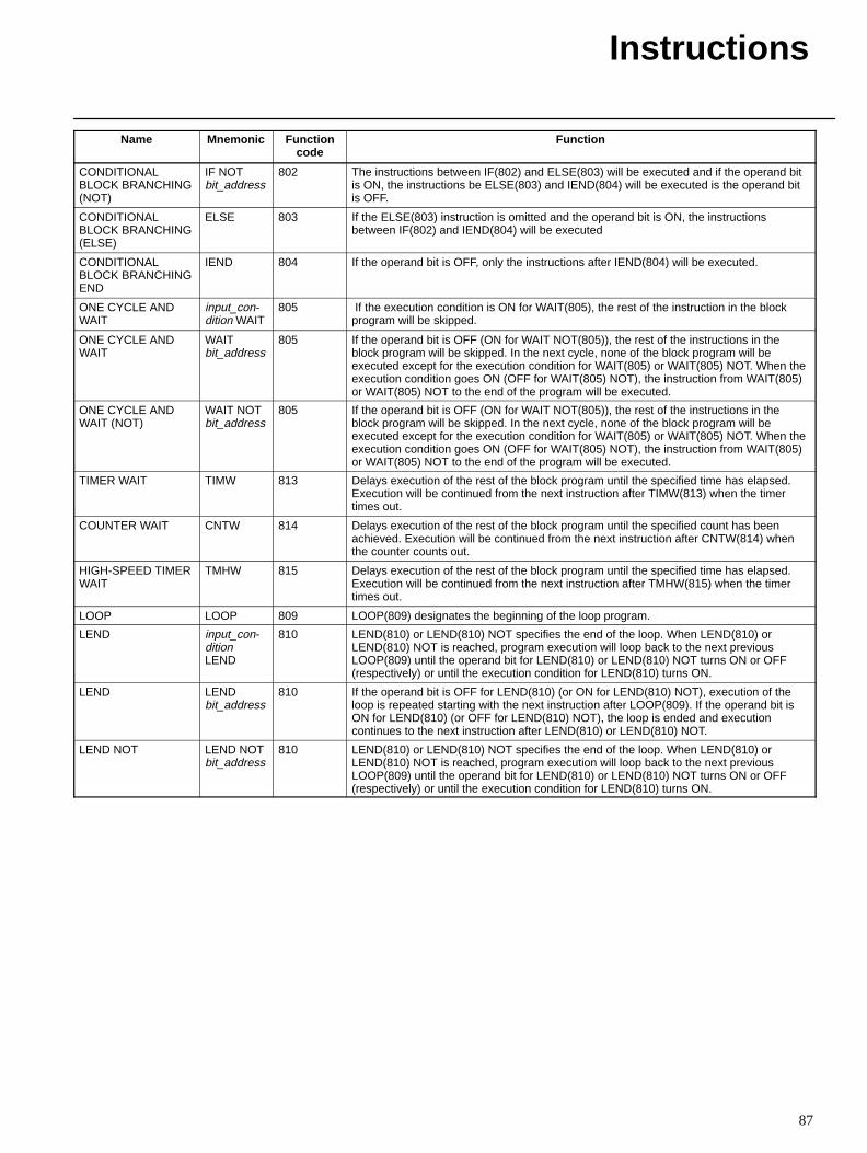
Instructions
87
Name FunctionFunctioncode
Mnemonic
CONDITIONALBLOCK BRANCHING(NOT)
IF NOTbit_address
802 The instructions between IF(802) and ELSE(803) will be executed and if the operand bitis ON, the instructions be ELSE(803) and IEND(804) will be executed is the operand bitis OFF.
CONDITIONALBLOCK BRANCHING(ELSE)
ELSE 803 If the ELSE(803) instruction is omitted and the operand bit is ON, the instructionsbetween IF(802) and IEND(804) will be executed
CONDITIONALBLOCK BRANCHINGEND
IEND 804 If the operand bit is OFF, only the instructions after IEND(804) will be executed.
ONE CYCLE ANDWAIT
input_con-dition WAIT
805 If the execution condition is ON for WAIT(805), the rest of the instruction in the blockprogram will be skipped.
ONE CYCLE ANDWAIT
WAITbit_address
805 If the operand bit is OFF (ON for WAIT NOT(805)), the rest of the instructions in theblock program will be skipped. In the next cycle, none of the block program will beexecuted except for the execution condition for WAIT(805) or WAIT(805) NOT. When theexecution condition goes ON (OFF for WAIT(805) NOT), the instruction from WAIT(805)or WAIT(805) NOT to the end of the program will be executed.
ONE CYCLE ANDWAIT (NOT)
WAIT NOTbit_address
805 If the operand bit is OFF (ON for WAIT NOT(805)), the rest of the instructions in theblock program will be skipped. In the next cycle, none of the block program will beexecuted except for the execution condition for WAIT(805) or WAIT(805) NOT. When theexecution condition goes ON (OFF for WAIT(805) NOT), the instruction from WAIT(805)or WAIT(805) NOT to the end of the program will be executed.
TIMER WAIT TIMW 813 Delays execution of the rest of the block program until the specified time has elapsed.Execution will be continued from the next instruction after TIMW(813) when the timertimes out.
COUNTER WAIT CNTW 814 Delays execution of the rest of the block program until the specified count has beenachieved. Execution will be continued from the next instruction after CNTW(814) whenthe counter counts out.
HIGH-SPEED TIMERWAIT
TMHW 815 Delays execution of the rest of the block program until the specified time has elapsed.Execution will be continued from the next instruction after TMHW(815) when the timertimes out.
LOOP LOOP 809 LOOP(809) designates the beginning of the loop program.
LEND input_con-ditionLEND
810 LEND(810) or LEND(810) NOT specifies the end of the loop. When LEND(810) orLEND(810) NOT is reached, program execution will loop back to the next previousLOOP(809) until the operand bit for LEND(810) or LEND(810) NOT turns ON or OFF(respectively) or until the execution condition for LEND(810) turns ON.
LEND LENDbit_address
810 If the operand bit is OFF for LEND(810) (or ON for LEND(810) NOT), execution of theloop is repeated starting with the next instruction after LOOP(809). If the operand bit isON for LEND(810) (or OFF for LEND(810) NOT), the loop is ended and executioncontinues to the next instruction after LEND(810) or LEND(810) NOT.
LEND NOT LEND NOTbit_address
810 LEND(810) or LEND(810) NOT specifies the end of the loop. When LEND(810) orLEND(810) NOT is reached, program execution will loop back to the next previousLOOP(809) until the operand bit for LEND(810) or LEND(810) NOT turns ON or OFF(respectively) or until the execution condition for LEND(810) turns ON.
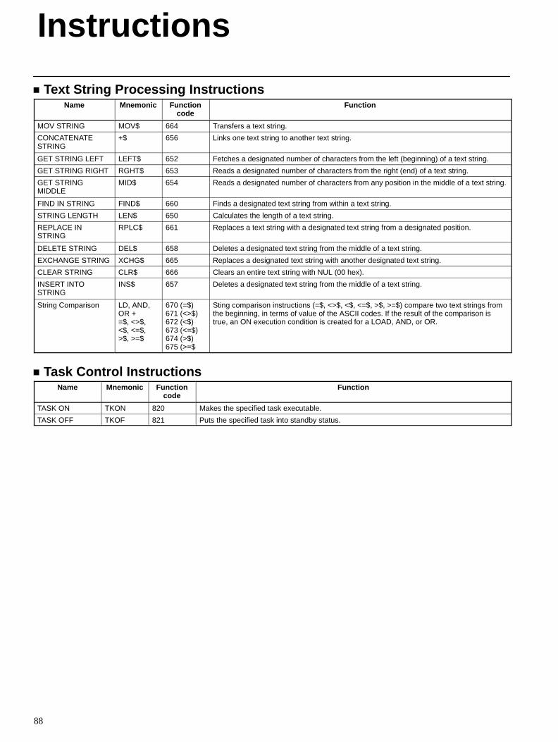
Instructions
88
Text String Processing InstructionsName Mnemonic Function
codeFunction
MOV STRING MOV$ 664 Transfers a text string.
CONCATENATESTRING
+$ 656 Links one text string to another text string.
GET STRING LEFT LEFT$ 652 Fetches a designated number of characters from the left (beginning) of a text string.
GET STRING RIGHT RGHT$ 653 Reads a designated number of characters from the right (end) of a text string.
GET STRINGMIDDLE
MID$ 654 Reads a designated number of characters from any position in the middle of a text string.
FIND IN STRING FIND$ 660 Finds a designated text string from within a text string.
STRING LENGTH LEN$ 650 Calculates the length of a text string.
REPLACE INSTRING
RPLC$ 661 Replaces a text string with a designated text string from a designated position.
DELETE STRING DEL$ 658 Deletes a designated text string from the middle of a text string.
EXCHANGE STRING XCHG$ 665 Replaces a designated text string with another designated text string.
CLEAR STRING CLR$ 666 Clears an entire text string with NUL (00 hex).
INSERT INTOSTRING
INS$ 657 Deletes a designated text string from the middle of a text string.
String Comparison LD, AND,OR +=$, <>$,<$, <=$,>$, >=$
670 (=$)671 (<>$)672 (<$)673 (<=$)674 (>$)675 (>=$
Sting comparison instructions (=$, <>$, <$, <=$, >$, >=$) compare two text strings fromthe beginning, in terms of value of the ASCII codes. If the result of the comparison istrue, an ON execution condition is created for a LOAD, AND, or OR.
Task Control InstructionsName Mnemonic Function
codeFunction
TASK ON TKON 820 Makes the specified task executable.
TASK OFF TKOF 821 Puts the specified task into standby status.
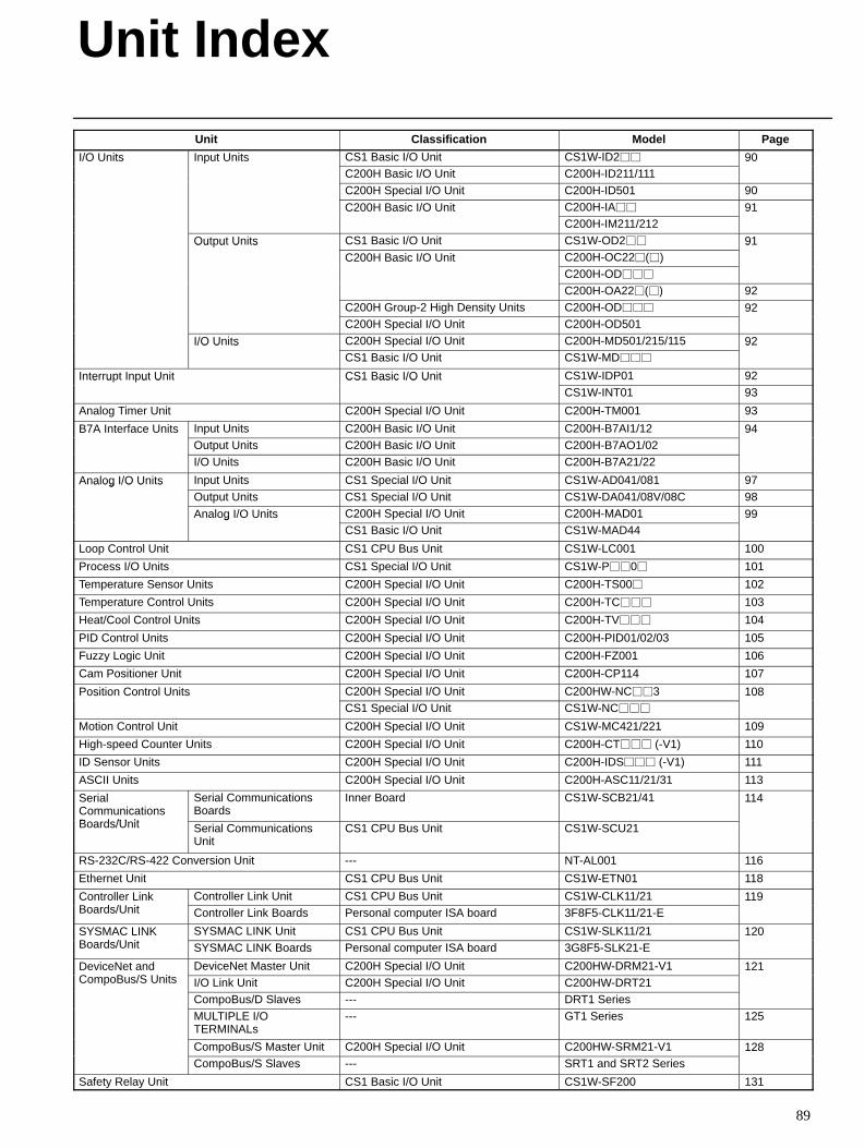
89
Unit Classification Model Page
I/O Units Input Units CS1 Basic I/O Unit CS1W-ID2 90/O U s u U sC200H Basic I/O Unit C200H-ID211/111
90
C200H Special I/O Unit C200H-ID501 90
C200H Basic I/O Unit C200H-IA 91C 00 as c /O UC200H-IM211/212
9
Output Units CS1 Basic I/O Unit CS1W-OD2 91Ou u U sC200H Basic I/O Unit C200H-OC22()
9C 00 as c /O U
C200H-OD
C200H-OA22() 92C200H Group-2 High Density Units C200H-OD 92C200H Special I/O Unit C200H-OD501
9
I/O Units C200H Special I/O Unit C200H-MD501/215/115 92/O U sCS1 Basic I/O Unit CS1W-MD
9
Interrupt Input Unit CS1 Basic I/O Unit CS1W-IDP01 92e u u U CS as c /O UCS1W-INT01 93
Analog Timer Unit C200H Special I/O Unit C200H-TM001 93
B7A Interface Units Input Units C200H Basic I/O Unit C200H-B7AI1/12 94e ace U sOutput Units C200H Basic I/O Unit C200H-B7AO1/02
9
I/O Units C200H Basic I/O Unit C200H-B7A21/22
Analog I/O Units Input Units CS1 Special I/O Unit CS1W-AD041/081 97a og /O U sOutput Units CS1 Special I/O Unit CS1W-DA041/08V/08C 98
Analog I/O Units C200H Special I/O Unit C200H-MAD01 99a og /O U sCS1 Basic I/O Unit CS1W-MAD44
99
Loop Control Unit CS1 CPU Bus Unit CS1W-LC001 100
Process I/O Units CS1 Special I/O Unit CS1W-P0 101
Temperature Sensor Units C200H Special I/O Unit C200H-TS00 102
Temperature Control Units C200H Special I/O Unit C200H-TC 103
Heat/Cool Control Units C200H Special I/O Unit C200H-TV 104
PID Control Units C200H Special I/O Unit C200H-PID01/02/03 105
Fuzzy Logic Unit C200H Special I/O Unit C200H-FZ001 106
Cam Positioner Unit C200H Special I/O Unit C200H-CP114 107
Position Control Units C200H Special I/O Unit C200HW-NC3 108os o Co o U sCS1 Special I/O Unit CS1W-NC
08
Motion Control Unit C200H Special I/O Unit CS1W-MC421/221 109
High-speed Counter Units C200H Special I/O Unit C200H-CT (-V1) 110
ID Sensor Units C200H Special I/O Unit C200H-IDS (-V1) 111
ASCII Units C200H Special I/O Unit C200H-ASC11/21/31 113
SerialCommunicationsB d /U it
Serial CommunicationsBoards
Inner Board CS1W-SCB21/41 114
Boards/Unit Serial CommunicationsUnit
CS1 CPU Bus Unit CS1W-SCU21
RS-232C/RS-422 Conversion Unit --- NT-AL001 116
Ethernet Unit CS1 CPU Bus Unit CS1W-ETN01 118
Controller LinkB d /U it
Controller Link Unit CS1 CPU Bus Unit CS1W-CLK11/21 119Co o eBoards/Unit Controller Link Boards Personal computer ISA board 3F8F5-CLK11/21-E
9
SYSMAC LINKB d /U it
SYSMAC LINK Unit CS1 CPU Bus Unit CS1W-SLK11/21 120S S CBoards/Unit SYSMAC LINK Boards Personal computer ISA board 3G8F5-SLK21-E
0
DeviceNet andC B /S U it
DeviceNet Master Unit C200H Special I/O Unit C200HW-DRM21-V1 121e ce e a dCompoBus/S Units I/O Link Unit C200H Special I/O Unit C200HW-DRT21
CompoBus/D Slaves --- DRT1 Series
MULTIPLE I/OTERMINALs
--- GT1 Series 125
CompoBus/S Master Unit C200H Special I/O Unit C200HW-SRM21-V1 128CompoBus/S Slaves --- SRT1 and SRT2 Series
8
Safety Relay Unit CS1 Basic I/O Unit CS1W-SF200 131
Unit Index
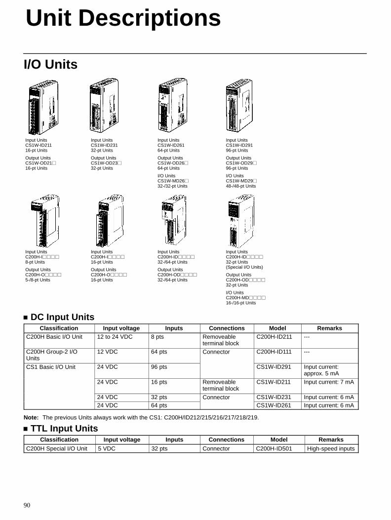
90
I/O Units
Input UnitsC200H-I
8-pt Units
Output UnitsC200H-O
5-/8-pt Units
Input UnitsC200H-I
16-pt Units
Output UnitsC200H-O
16-pt Units
Input UnitsC200H-ID
32-/64-pt Units
Output UnitsC200H-OD
32-/64-pt Units
Input UnitsC200H-ID
32-pt Units (Special I/O Units)
Output UnitsC200H-OD
32-pt Units
I/O UnitsC200H-MD
16-/16-pt Units
Input UnitsCS1W-ID29196-pt Units
Output UnitsCS1W-OD2996-pt Units
I/O UnitsCS1W-MD2948-/48-pt Units
Input UnitsCS1W-ID21116-pt Units
Output UnitsCS1W-OD2116-pt Units
Input UnitsCS1W-ID23132-pt Units
Output UnitsCS1W-OD2332-pt Units
Input UnitsCS1W-ID26164-pt Units
Output UnitsCS1W-OD2664-pt Units
I/O UnitsCS1W-MD2632-/32-pt Units
DC Input UnitsClassification Input voltage Inputs Connections Model Remarks
C200H Basic I/O Unit 12 to 24 VDC 8 pts Removeableterminal block
C200H-ID211 ---
C200H Group-2 I/OUnits
12 VDC 64 pts Connector C200H-ID111 ---
CS1 Basic I/O Unit 24 VDC 96 pts CS1W-ID291 Input current:approx. 5 mA
24 VDC 16 pts Removeableterminal block
CS1W-ID211 Input current: 7 mA
24 VDC 32 pts Connector CS1W-ID231 Input current: 6 mA24 VDC 64 pts CS1W-ID261 Input current: 6 mA
Note: The previous Units always work with the CS1: C200H/ID212/215/216/217/218/219.
TTL Input UnitsClassification Input voltage Inputs Connections Model Remarks
C200H Special I/O Unit 5 VDC 32 pts Connector C200H-ID501 High-speed inputs
Unit Descriptions
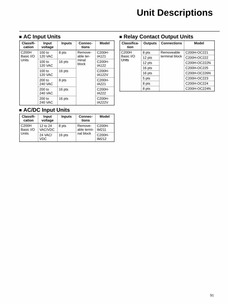
Unit Descriptions
91
AC Input UnitsClassifi-cation
Inputvoltage
Inputs Connec-tions
Model
C200HBasic I/OU it
100 to120 VAC
8 pts Remove-able ter-
i l
C200H-IA121
Units 100 to120 VAC
16 pts minalblock
C200H-IA122
100 to120 VAC
16 pts C200H-IA122V
200 to240 VAC
8 pts C200H-IA221
200 to240 VAC
16 pts C200H-IA222
200 to240 VAC
16 pts C200H-IA222V
AC/DC Input UnitsClassifi-cation
Inputvoltage
Inputs Connec-tions
Model
C200HBasic I/OU it
12 to 24VAC/VDC
8 pts Remove-able termi-
l bl k
C200H-IM211
Units 24 VAC/VDC
16 pts nal block C200H-IM212
Relay Contact Output UnitsClassifica-
tionOutputs Connections Model
C200HB i I/O
8 pts Removeablei l bl k
C200H-OC221Basic I/OUnits
12 pts terminal block C200H-OC222Units
12 pts C200H-OC222N
16 pts C200H-OC225
16 pts C200H-OC226N
5 pts C200H-OC223
8 pts C200H-OC224
8 pts C200H-OC224N
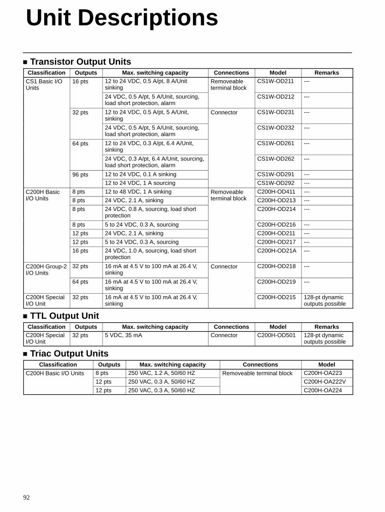
Unit Descriptions
92
Transistor Output UnitsClassification Outputs Max. switching capacity Connections Model Remarks
CS1 Basic I/OUnits
16 pts 12 to 24 VDC, 0.5 A/pt, 8 A/Unitsinking
Removeableterminal block
CS1W-OD211 ---
24 VDC, 0.5 A/pt, 5 A/Unit, sourcing,load short protection, alarm
CS1W-OD212 ---
32 pts 12 to 24 VDC, 0.5 A/pt, 5 A/Unit,sinking
Connector CS1W-OD231 ---
24 VDC, 0.5 A/pt, 5 A/Unit, sourcing,load short protection, alarm
CS1W-OD232 ---
64 pts 12 to 24 VDC, 0.3 A/pt, 6.4 A/Unit,sinking
CS1W-OD261 ---
24 VDC, 0.3 A/pt, 6.4 A/Unit, sourcing,load short protection, alarm
CS1W-OD262 ---
96 pts 12 to 24 VDC, 0.1 A sinking CS1W-OD291 ---
12 to 24 VDC, 1 A sourcing CS1W-OD292 ---
C200H BasicI/O U i
8 pts 12 to 48 VDC, 1 A sinking Removeablei l bl k
C200H-OD411 ---I/O Units 8 pts 24 VDC, 2.1 A, sinking terminal block C200H-OD213 ---
8 pts 24 VDC, 0.8 A, sourcing, load shortprotection
C200H-OD214 ---
8 pts 5 to 24 VDC, 0.3 A, sourcing C200H-OD216 ---
12 pts 24 VDC, 2.1 A, sinking C200H-OD211 ---
12 pts 5 to 24 VDC, 0.3 A, sourcing C200H-OD217 ---
16 pts 24 VDC, 1.0 A, sourcing, load shortprotection
C200H-OD21A ---
C200H Group-2I/O Units
32 pts 16 mA at 4.5 V to 100 mA at 26.4 V,sinking
Connector C200H-OD218 ---
64 pts 16 mA at 4.5 V to 100 mA at 26.4 V,sinking
C200H-OD219 ---
C200H SpecialI/O Unit
32 pts 16 mA at 4.5 V to 100 mA at 26.4 V,sinking
C200H-OD215 128-pt dynamicoutputs possible
TTL Output UnitClassification Outputs Max. switching capacity Connections Model Remarks
C200H SpecialI/O Unit
32 pts 5 VDC, 35 mA Connector C200H-OD501 128-pt dynamicoutputs possible
Triac Output UnitsClassification Outputs Max. switching capacity Connections Model
C200H Basic I/O Units 8 pts 250 VAC, 1.2 A, 50/60 HZ Removeable terminal block C200H-OA223
12 pts 250 VAC, 0.3 A, 50/60 HZ C200H-OA222V
12 pts 250 VAC, 0.3 A, 50/60 HZ C200H-OA224
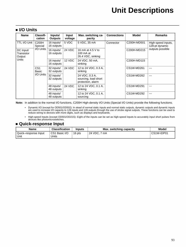
Unit Descriptions
93
I/O UnitsName Classifi- Inputs/ Input Max. switchin g ca- Connections Model RemarksName Classifi
cationInputs/
OutputsInput
voltageMax. switching ca
pacityConnections Model Remarks
TTL I/O Unit C200HSpecialI/O U it
16 inputs/16 outputs
5 VDC 5 VDC, 35 mA Connector C200H-MD501 High-speed inputs,128-pt dynamic
t t iblDC Input/TransistorOutputU it
I/O Units 16 inputs/16 outputs
24 VDC 16 mA at 4.5 V to100 mA at26.4 VDC, sinking
C200H-MD215
youtputs possible
Units 16 inputs/16 outputs
12 VDC 24 VDC, 50 mA,sinking
C200H-MD115
CS1BasicI/O U it
32 inputs/32 outputs
24 VDC 12 to 24 VDC, 0.3 A,sinking
CS1W-MD261 ---
I/O Units 32 inputs/32 outputs
24 VDC, 0.3 A,sourcing, load shortprotection, alarm
CS1W-MD262 ---
48 inputs/48 outputs
24 VDC 12 to 24 VDC, 0.1 A,sinking
CS1W-MD291 ---
48 inputs/48 outputs
12 to 24 VDC, 0.1 A,sourcing
CS1W-MD292 ---
Note: In addition to the normal I/O functions, C200H High-density I/O Units (Special I/O Units) provide the following functions.
• Dynamic I/O (except for OD501/OD502): In stead of normal static inputs and normal static outputs, dynamic outputs and dynamic inputsare used to increase I/O capacity to 128 inputs and 128 outputs through the use of strobe signal outputs. These functions can be used toreduce wiring to devices with more digits, such as displays and keyboards.
• High-speed Inputs (except OD501/OD215): Eight of the inputs can be set as high-speed inputs to accurately input short pulses fromdevices like photomicroswitches.
Quick-response InputName Classification Inputs Max. switching capacity Model
Quick–response InputUnit
CS1 Basic I/OUnits
16 pts 24 VDC, 7 mA CS1W-IDP01
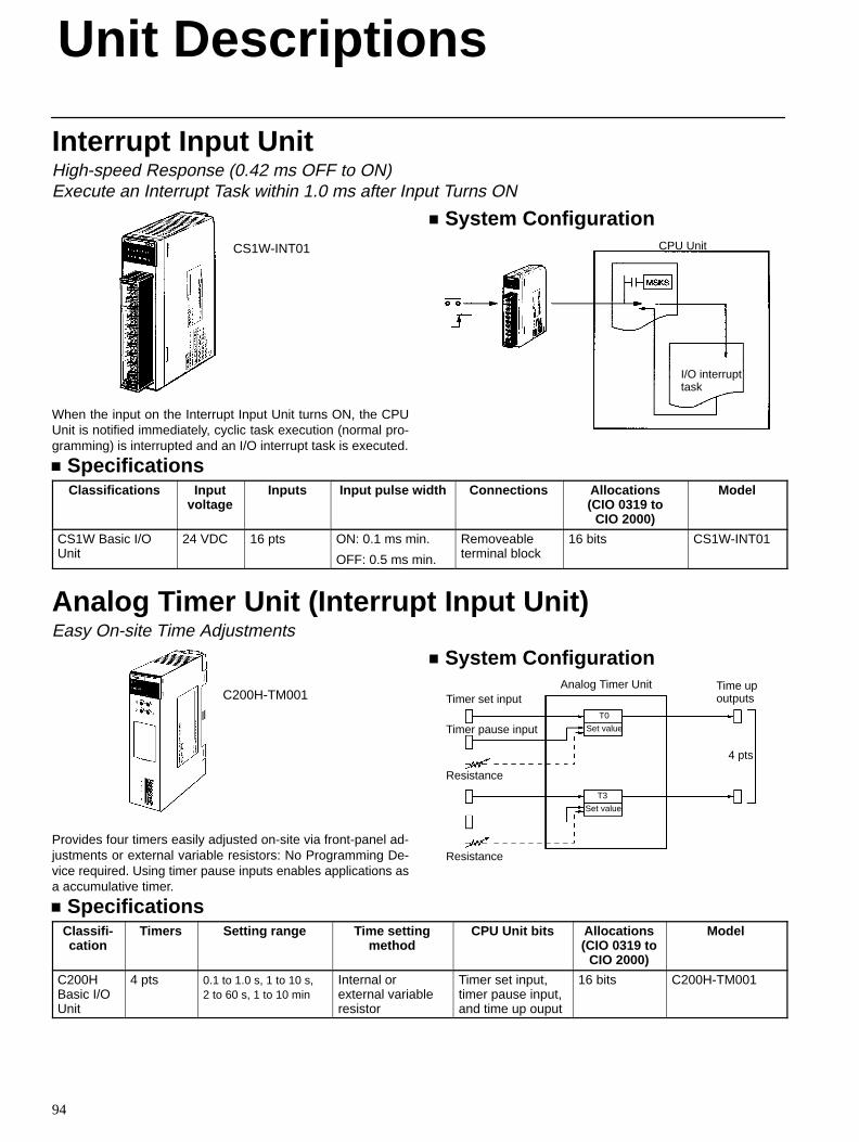
Unit Descriptions
94
Interrupt Input UnitHigh-speed Response (0.42 ms OFF to ON)Execute an Interrupt Task within 1.0 ms after Input Turns ON
CS1W-INT01
When the input on the Interrupt Input Unit turns ON, the CPUUnit is notified immediately, cyclic task execution (normal pro-gramming) is interrupted and an I/O interrupt task is executed.
System ConfigurationCPU Unit
I/O interrupttask
SpecificationsClassifications Input
voltageInputs Input pulse width Connections Allocations
(CIO 0319 toCIO 2000)
Model
CS1W Basic I/OUnit
24 VDC 16 pts ON: 0.1 ms min.
OFF: 0.5 ms min.
Removeableterminal block
16 bits CS1W-INT01
Analog Timer Unit (Interrupt Input Unit)Easy On-site Time Adjustments
C200H-TM001
Provides four timers easily adjusted on-site via front-panel ad-justments or external variable resistors: No Programming De-vice required. Using timer pause inputs enables applications asa accumulative timer.
System Configuration
Timer set input
Timer pause input
Resistance
Resistance
Analog Timer Unit
T0
Set value
T3
Set value
Time upoutputs
4 pts
SpecificationsClassifi-cation
Timers Setting range Time settingmethod
CPU Unit bits Allocations(CIO 0319 to
CIO 2000)
Model
C200HBasic I/OUnit
4 pts 0.1 to 1.0 s, 1 to 10 s,2 to 60 s, 1 to 10 min
Internal orexternal variableresistor
Timer set input,timer pause input,and time up ouput
16 bits C200H-TM001
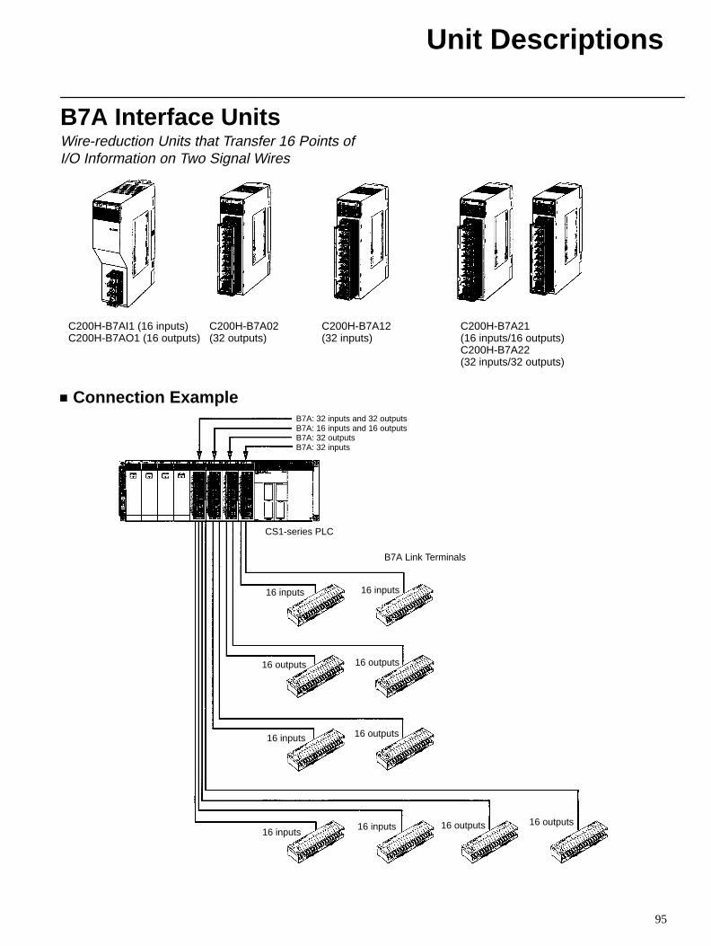
Unit Descriptions
95
B7A Interface UnitsWire-reduction Units that Transfer 16 Points ofI/O Information on Two Signal Wires
C200H-B7AI1 (16 inputs)C200H-B7AO1 (16 outputs)
C200H-B7A02(32 outputs)
C200H-B7A12(32 inputs)
C200H-B7A21(16 inputs/16 outputs)C200H-B7A22(32 inputs/32 outputs)
Connection ExampleB7A: 32 inputs and 32 outputsB7A: 16 inputs and 16 outputsB7A: 32 outputsB7A: 32 inputs
CS1-series PLC
16 inputs 16 inputs
B7A Link Terminals
16 outputs 16 outputs
16 outputs16 inputs
16 inputs16 inputs 16 outputs 16 outputs
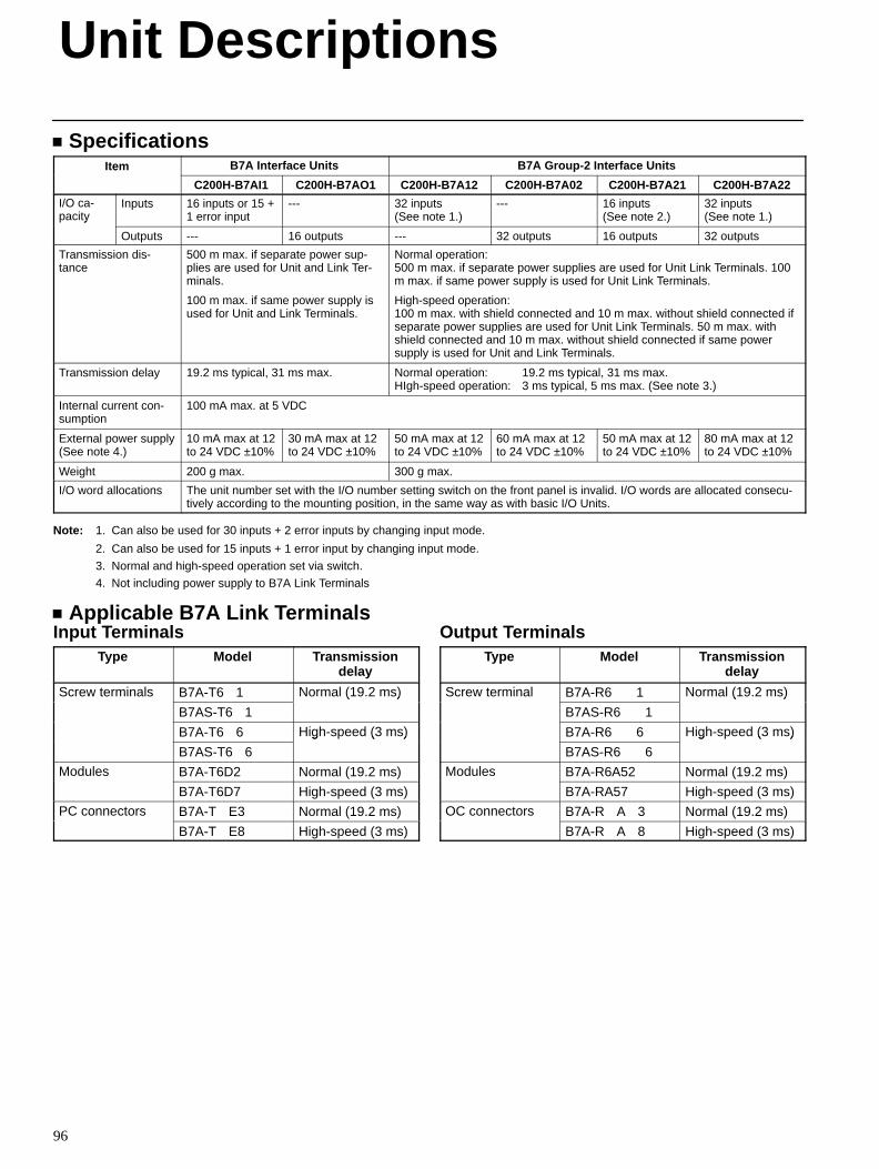
Unit Descriptions
96
SpecificationsItem B7A Interface Units B7A Group-2 Interface Unitse
C200H-B7AI1 C200H-B7AO1 C200H-B7A12 C200H-B7A02 C200H-B7A21 C200H-B7A22
I/O ca-pacity
Inputs 16 inputs or 15 +1 error input
--- 32 inputs (See note 1.)
--- 16 inputs (See note 2.)
32 inputs (See note 1.)y
Outputs --- 16 outputs --- 32 outputs 16 outputs 32 outputs
Transmission dis-tance
500 m max. if separate power sup-plies are used for Unit and Link Ter-minals.
100 m max. if same power supply isused for Unit and Link Terminals.
Normal operation:500 m max. if separate power supplies are used for Unit Link Terminals. 100m max. if same power supply is used for Unit Link Terminals.
High-speed operation:100 m max. with shield connected and 10 m max. without shield connected ifseparate power supplies are used for Unit Link Terminals. 50 m max. withshield connected and 10 m max. without shield connected if same powersupply is used for Unit and Link Terminals.
Transmission delay 19.2 ms typical, 31 ms max. Normal operation: 19.2 ms typical, 31 ms max.HIgh-speed operation: 3 ms typical, 5 ms max. (See note 3.)
Internal current con-sumption
100 mA max. at 5 VDC
External power supply(See note 4.)
10 mA max at 12to 24 VDC ±10%
30 mA max at 12to 24 VDC ±10%
50 mA max at 12to 24 VDC ±10%
60 mA max at 12to 24 VDC ±10%
50 mA max at 12to 24 VDC ±10%
80 mA max at 12to 24 VDC ±10%
Weight 200 g max. 300 g max.
I/O word allocations The unit number set with the I/O number setting switch on the front panel is invalid. I/O words are allocated consecu-tively according to the mounting position, in the same way as with basic I/O Units.
Note: 1. Can also be used for 30 inputs + 2 error inputs by changing input mode.
2. Can also be used for 15 inputs + 1 error input by changing input mode.
3. Normal and high-speed operation set via switch.
4. Not including power supply to B7A Link Terminals
Applicable B7A Link TerminalsInput Terminals
Type Model Transmissiondelay
Screw terminals B7A-T61 Normal (19.2 ms)
B7AS-T61
( )
B7A-T66 High-speed (3 ms)
B7AS-T66
g ( )
Modules B7A-T6D2 Normal (19.2 ms)
B7A-T6D7 High-speed (3 ms)
PC connectors B7A-TE3 Normal (19.2 ms)
B7A-TE8 High-speed (3 ms)
Output TerminalsType Model Transmission
delay
Screw terminal B7A-R61 Normal (19.2 ms)
B7AS-R61
( )
B7A-R66 High-speed (3 ms)
B7AS-R66
g ( )
Modules B7A-R6A52 Normal (19.2 ms)
B7A-RA57 High-speed (3 ms)
OC connectors B7A-RA3 Normal (19.2 ms)
B7A-RA8 High-speed (3 ms)
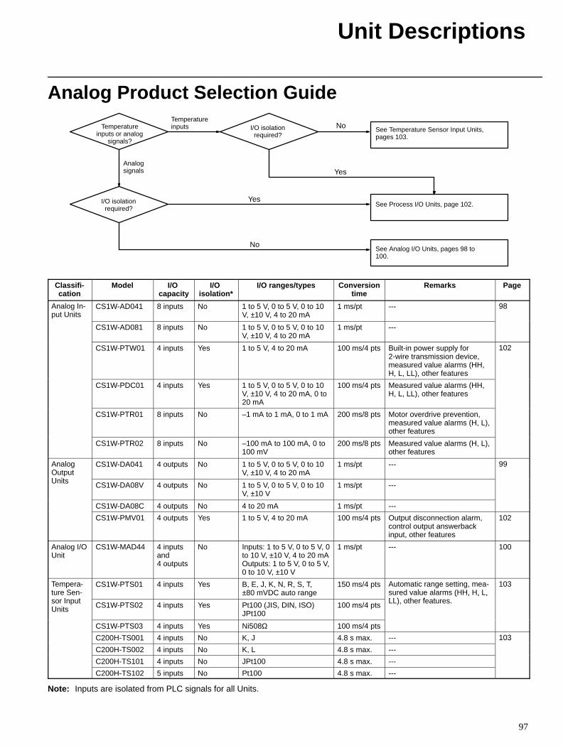
Unit Descriptions
97
Analog Product Selection Guide
No
No
Yes
Yes
Temperatureinputs or analog
signals?
Temperatureinputs
Analogsignals
I/O isolationrequired?
I/O isolationrequired?
See Temperature Sensor Input Units,pages 103.
See Process I/O Units, page 102.
See Analog I/O Units, pages 98 to100.
Classifi-cation
Model I/O capacity
I/O isolation*
I/O ranges/types Conversiontime
Remarks Page
Analog In-put Units
CS1W-AD041 8 inputs No 1 to 5 V, 0 to 5 V, 0 to 10V, ±10 V, 4 to 20 mA
1 ms/pt --- 98
CS1W-AD081 8 inputs No 1 to 5 V, 0 to 5 V, 0 to 10V, ±10 V, 4 to 20 mA
1 ms/pt ---
CS1W-PTW01 4 inputs Yes 1 to 5 V, 4 to 20 mA 100 ms/4 pts Built-in power supply for2-wire transmission device, measured value alarms (HH,H, L, LL), other features
102
CS1W-PDC01 4 inputs Yes 1 to 5 V, 0 to 5 V, 0 to 10V, ±10 V, 4 to 20 mA, 0 to20 mA
100 ms/4 pts Measured value alarms (HH,H, L, LL), other features
CS1W-PTR01 8 inputs No –1 mA to 1 mA, 0 to 1 mA 200 ms/8 pts Motor overdrive prevention,measured value alarms (H, L),other features
CS1W-PTR02 8 inputs No –100 mA to 100 mA, 0 to100 mV
200 ms/8 pts Measured value alarms (H, L),other features
AnalogOutputU it
CS1W-DA041 4 outputs No 1 to 5 V, 0 to 5 V, 0 to 10V, ±10 V, 4 to 20 mA
1 ms/pt --- 99
Units CS1W-DA08V 4 outputs No 1 to 5 V, 0 to 5 V, 0 to 10V, ±10 V
1 ms/pt ---
CS1W-DA08C 4 outputs No 4 to 20 mA 1 ms/pt ---
CS1W-PMV01 4 outputs Yes 1 to 5 V, 4 to 20 mA 100 ms/4 pts Output disconnection alarm,control output answerbackinput, other features
102
Analog I/OUnit
CS1W-MAD44 4 inputsand 4 outputs
No Inputs: 1 to 5 V, 0 to 5 V, 0to 10 V, ±10 V, 4 to 20 mAOutputs: 1 to 5 V, 0 to 5 V,0 to 10 V, ±10 V
1 ms/pt --- 100
Tempera-ture Sen-
I t
CS1W-PTS01 4 inputs Yes B, E, J, K, N, R, S, T,±80 mVDC auto range
150 ms/4 pts Automatic range setting, mea-sured value alarms (HH, H, L,LL) th f t
103
sor InputUnits CS1W-PTS02 4 inputs Yes Pt100 (JIS, DIN, ISO)
JPt100100 ms/4 pts
( , , ,LL), other features.
CS1W-PTS03 4 inputs Yes Ni508Ω 100 ms/4 pts
C200H-TS001 4 inputs No K, J 4.8 s max. --- 103
C200H-TS002 4 inputs No K, L 4.8 s max. ---
03
C200H-TS101 4 inputs No JPt100 4.8 s max. ---
C200H-TS102 5 inputs No Pt100 4.8 s max. ---
Note: Inputs are isolated from PLC signals for all Units.
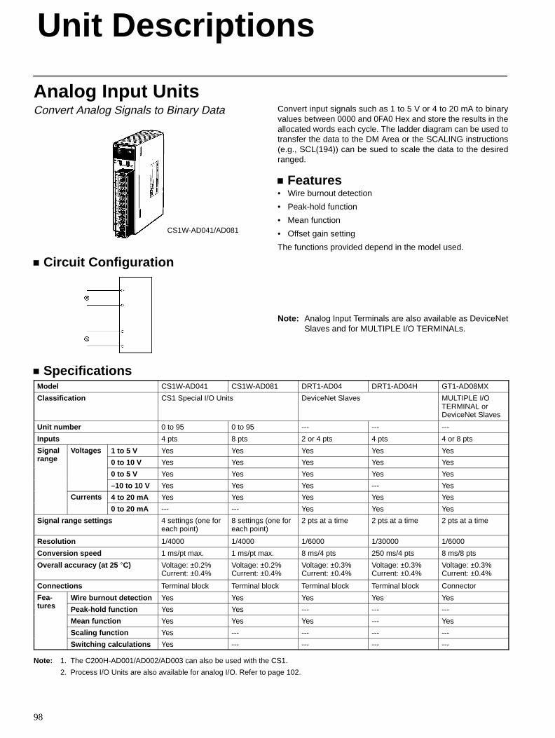
Unit Descriptions
98
Analog Input UnitsConvert Analog Signals to Binary Data
CS1W-AD041/AD081
Circuit Configuration
Convert input signals such as 1 to 5 V or 4 to 20 mA to binaryvalues between 0000 and 0FA0 Hex and store the results in theallocated words each cycle. The ladder diagram can be used totransfer the data to the DM Area or the SCALING instructions(e.g., SCL(194)) can be sued to scale the data to the desiredranged.
Features• Wire burnout detection
• Peak-hold function
• Mean function
• Offset gain setting
The functions provided depend in the model used.
Note: Analog Input Terminals are also available as DeviceNetSlaves and for MULTIPLE I/O TERMINALs.
SpecificationsModel CS1W-AD041 CS1W-AD081 DRT1-AD04 DRT1-AD04H GT1-AD08MX
Classification CS1 Special I/O Units DeviceNet Slaves MULTIPLE I/OTERMINAL orDeviceNet Slaves
Unit number 0 to 95 0 to 95 --- --- ---
Inputs 4 pts 8 pts 2 or 4 pts 4 pts 4 or 8 pts
Signal Voltages 1 to 5 V Yes Yes Yes Yes YesS g arange
o ages
0 to 10 V Yes Yes Yes Yes Yes
0 to 5 V Yes Yes Yes Yes Yes
–10 to 10 V Yes Yes Yes --- Yes
Currents 4 to 20 mA Yes Yes Yes Yes YesCu e s
0 to 20 mA --- --- Yes Yes Yes
Signal range settings 4 settings (one foreach point)
8 settings (one foreach point)
2 pts at a time 2 pts at a time 2 pts at a time
Resolution 1/4000 1/4000 1/6000 1/30000 1/6000
Conversion speed 1 ms/pt max. 1 ms/pt max. 8 ms/4 pts 250 ms/4 pts 8 ms/8 pts
Overall accuracy (at 25 °C) Voltage: ±0.2%Current: ±0.4%
Voltage: ±0.2%Current: ±0.4%
Voltage: ±0.3%Current: ±0.4%
Voltage: ±0.3%Current: ±0.4%
Voltage: ±0.3%Current: ±0.4%
Connections Terminal block Terminal block Terminal block Terminal block Connector
Fea-t
Wire burnout detection Yes Yes Yes Yes Yeseatures Peak-hold function Yes Yes --- --- ---
Mean function Yes Yes Yes --- Yes
Scaling function Yes --- --- --- ---
Switching calculations Yes --- --- --- ---
Note: 1. The C200H-AD001/AD002/AD003 can also be used with the CS1.
2. Process I/O Units are also available for analog I/O. Refer to page 102.
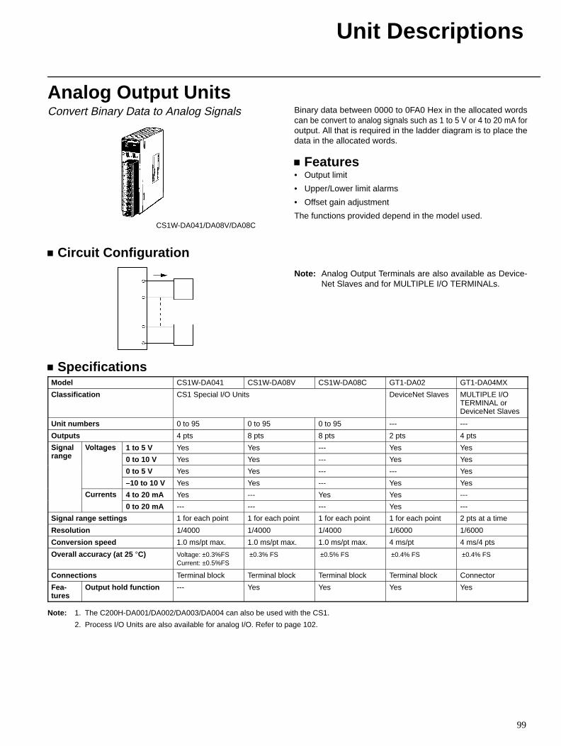
Unit Descriptions
99
Analog Output UnitsConvert Binary Data to Analog Signals
CS1W-DA041/DA08V/DA08C
Circuit Configuration
Binary data between 0000 to 0FA0 Hex in the allocated wordscan be convert to analog signals such as 1 to 5 V or 4 to 20 mA foroutput. All that is required in the ladder diagram is to place thedata in the allocated words.
Features• Output limit
• Upper/Lower limit alarms
• Offset gain adjustment
The functions provided depend in the model used.
Note: Analog Output Terminals are also available as Device-Net Slaves and for MULTIPLE I/O TERMINALs.
SpecificationsModel CS1W-DA041 CS1W-DA08V CS1W-DA08C GT1-DA02 GT1-DA04MX
Classification CS1 Special I/O Units DeviceNet Slaves MULTIPLE I/OTERMINAL orDeviceNet Slaves
Unit numbers 0 to 95 0 to 95 0 to 95 --- ---
Outputs 4 pts 8 pts 8 pts 2 pts 4 pts
Signal Voltages 1 to 5 V Yes Yes --- Yes YesS g arange
o ages
0 to 10 V Yes Yes --- Yes Yes
0 to 5 V Yes Yes --- --- Yes
–10 to 10 V Yes Yes --- Yes Yes
Currents 4 to 20 mA Yes --- Yes Yes ---Cu e s
0 to 20 mA --- --- --- Yes ---
Signal range settings 1 for each point 1 for each point 1 for each point 1 for each point 2 pts at a time
Resolution 1/4000 1/4000 1/4000 1/6000 1/6000
Conversion speed 1.0 ms/pt max. 1.0 ms/pt max. 1.0 ms/pt max. 4 ms/pt 4 ms/4 pts
Overall accuracy (at 25 °C) Voltage: ±0.3%FSCurrent: ±0.5%FS
±0.3% FS ±0.5% FS ±0.4% FS ±0.4% FS
Connections Terminal block Terminal block Terminal block Terminal block Connector
Fea-tures
Output hold function --- Yes Yes Yes Yes
Note: 1. The C200H-DA001/DA002/DA003/DA004 can also be used with the CS1.
2. Process I/O Units are also available for analog I/O. Refer to page 102.
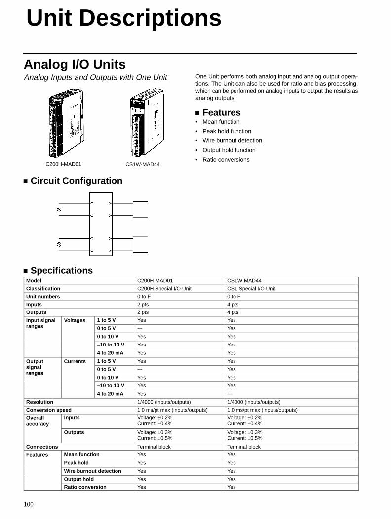
Unit Descriptions
100
Analog I/O UnitsAnalog Inputs and Outputs with One Unit
C200H-MAD01 CS1W-MAD44
Circuit Configuration
One Unit performs both analog input and analog output opera-tions. The Unit can also be used for ratio and bias processing,which can be performed on analog inputs to output the results asanalog outputs.
Features• Mean function
• Peak hold function
• Wire burnout detection
• Output hold function
• Ratio conversions
SpecificationsModel C200H-MAD01 CS1W-MAD44
Classification C200H Special I/O Unit CS1 Special I/O Unit
Unit numbers 0 to F 0 to F
Inputs 2 pts 4 pts
Outputs 2 pts 4 pts
Input signal Voltages 1 to 5 V Yes Yespu s g aranges
o ages
0 to 5 V --- Yes
0 to 10 V Yes Yes
–10 to 10 V Yes Yes
4 to 20 mA Yes Yes
Outputi l
Currents 1 to 5 V Yes YesOu pusignalranges
Cu e s
0 to 5 V --- Yesranges
0 to 10 V Yes Yes
–10 to 10 V Yes Yes
4 to 20 mA Yes ---
Resolution 1/4000 (inputs/outputs) 1/4000 (inputs/outputs)
Conversion speed 1.0 ms/pt max (inputs/outputs) 1.0 ms/pt max (inputs/outputs)
Overallaccuracy
Inputs Voltage: ±0.2%Current: ±0.4%
Voltage: ±0.2%Current: ±0.4%y
Outputs Voltage: ±0.3%Current: ±0.5%
Voltage: ±0.3%Current: ±0.5%
Connections Terminal block Terminal block
Features Mean function Yes Yesea u es
Peak hold Yes Yes
Wire burnout detection Yes Yes
Output hold Yes Yes
Ratio conversion Yes Yes
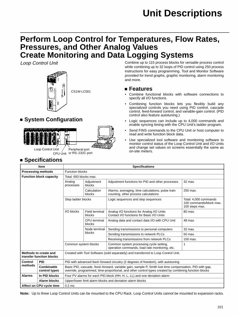
Unit Descriptions
101
Perform Loop Control for Temperatures, Flow Rates,Pressures, and Other Analog ValuesCreate Monitoring and Data Logging SystemsLoop Control Unit
CS1W-LC001
System Configuration
Peripheral portor RS–232C portCPU Unit
Loop Control Unit
Combine up to 115 process blocks for versatile process controlwhile combining up to 32 loops of PID control using 250 processinstructions for easy programming. Tool and Monitor Softwareprovided for trend graphs, graphic monitoring, alarm monitoringand more.
Features• Combine functional blocks with software connections to
specify all I/O functions.
• Combining function blocks lets you flexibly build anyspecialized controls you need using PID control, cascadecontrol, feed-forward control, and variable-gain control. (PIDcontrol also feature autotuning.)
• Logic sequences can include up to 4,000 commands andenable syncing timing with the CPU Unit’s ladder program.
• Send FINS commands to the CPU Unit or host computer toread and write function block data.
• Use specialized tool software and monitoring software tomonitor control status of the Loop Control Unit and I/O Unitsand change set values on screens essentially the same ason-site meters.
SpecificationsItem Specifications
Processing methods Function blocks
Function block capacity Total: 693 blocks max.u c o b oc capac y
Analogprocesses
Adjustmentblocks
Adjustment functions for PID and other processes 32 max.
Calculationblocks
Alarms, averaging, time calculations, pulse traincounting, other process calculations
250 max.
Step ladder blocks Logic sequences and step sequences Total: 4,000 commands100 commands/block max.100 steps max.
I/O blocks Field terminalblocks
Analog I/O functions for Analog I/O UnitsContact I/O functions for Basic I/O Units
80 max.
CPU terminalblocks
Analog data and contact data I/O with CPU Unit 48 max.
Node terminalbl k
Sending transmissions to personal computers 32 max.ode e ablocks Sending transmissions to network PLCs 50 max.
Receiving transmissions from network PLCs 100 max.
Common system blocks Common system processing cycle setting,operation commands, load rate monitoring, etc.
1
Methods to create andtransfer function blocks
Created with Tool Software (sold separately) and transferred to Loop Control Unit.
Controlth d
PID PID with advanced feed–forward circuitry (2 degrees of freedom), with autotuningCo omethods Combinable
control typesBasic PID, cascade, feed–forward, variable gain, sample P, Smith lost time compensation, PID with gap,override, programmed, time-proportional, and other control types created by combining function blocks
Alarms In PID blocks Four PV alarms for each PID block (HH, H, L, LL) and one deviation alarma s
Alarm blocks Upper/lower limit alarm blocks and deviation alarm blocks
Affect on CPU cycle time 0.2 ms
Note: Up to three Loop Control Units can be mounted to the CPU Rack. Loop Control Units cannot be mounted to expansion racks.
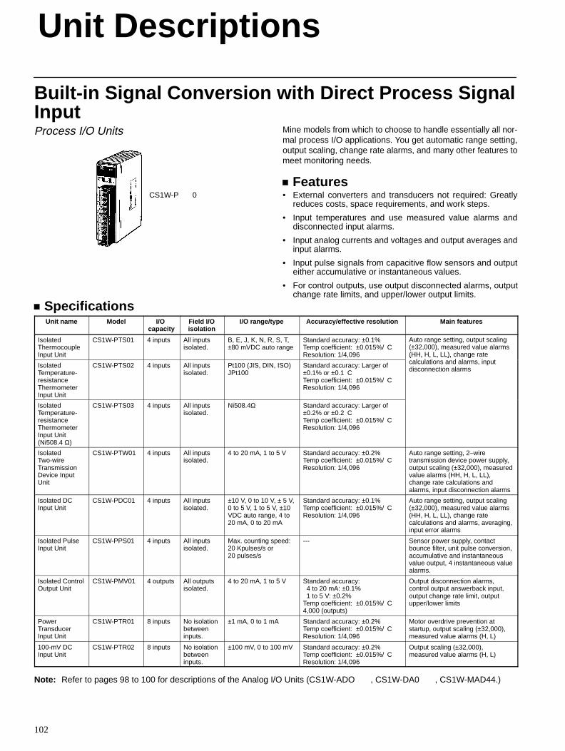
Unit Descriptions
102
Built-in Signal Conversion with Direct Process SignalInputProcess I/O Units
CS1W-P0
Mine models from which to choose to handle essentially all nor-mal process I/O applications. You get automatic range setting,output scaling, change rate alarms, and many other features tomeet monitoring needs.
Features• External converters and transducers not required: Greatly
reduces costs, space requirements, and work steps.
• Input temperatures and use measured value alarms anddisconnected input alarms.
• Input analog currents and voltages and output averages andinput alarms.
• Input pulse signals from capacitive flow sensors and outputeither accumulative or instantaneous values.
• For control outputs, use output disconnected alarms, outputchange rate limits, and upper/lower output limits.
SpecificationsUnit name Model I/O
capacityField I/Oisolation
I/O range/type Accuracy/effective resolution Main features
IsolatedThermocoupleInput Unit
CS1W-PTS01 4 inputs All inputsisolated.
B, E, J, K, N, R, S, T,±80 mVDC auto range
Standard accuracy: ±0.1%Temp coefficient: ±0.015%/CResolution: 1/4,096
Auto range setting, output scaling(±32,000), measured value alarms(HH, H, L, LL), change rate
l l ti d l i tIsolatedTemperature-resistanceThermometerInput Unit
CS1W-PTS02 4 inputs All inputsisolated.
Pt100 (JIS, DIN, ISO)JPt100
Standard accuracy: Larger of±0.1% or ±0.1CTemp coefficient: ±0.015%/CResolution: 1/4,096
(HH, H, L, LL), change ratecalculations and alarms, inputdisconnection alarms
IsolatedTemperature-resistanceThermometerInput Unit(Ni508.4 Ω)
CS1W-PTS03 4 inputs All inputsisolated.
Ni508.4Ω Standard accuracy: Larger of±0.2% or ±0.2CTemp coefficient: ±0.015%/CResolution: 1/4,096
IsolatedTwo-wireTransmissionDevice InputUnit
CS1W-PTW01 4 inputs All inputsisolated.
4 to 20 mA, 1 to 5 V Standard accuracy: ±0.2%Temp coefficient: ±0.015%/CResolution: 1/4,096
Auto range setting, 2–wiretransmission device power supply,output scaling (±32,000), measuredvalue alarms (HH, H, L, LL),change rate calculations andalarms, input disconnection alarms
Isolated DCInput Unit
CS1W-PDC01 4 inputs All inputsisolated.
±10 V, 0 to 10 V, ± 5 V,0 to 5 V, 1 to 5 V, ±10VDC auto range, 4 to20 mA, 0 to 20 mA
Standard accuracy: ±0.1%Temp coefficient: ±0.015%/CResolution: 1/4,096
Auto range setting, output scaling(±32,000), measured value alarms(HH, H, L, LL), change ratecalculations and alarms, averaging,input error alarms
Isolated PulseInput Unit
CS1W-PPS01 4 inputs All inputsisolated.
Max. counting speed:20 Kpulses/s or20 pulses/s
--- Sensor power supply, contactbounce filter, unit pulse conversion,accumulative and instantaneousvalue output, 4 instantaneous valuealarms.
Isolated ControlOutput Unit
CS1W-PMV01 4 outputs All outputsisolated.
4 to 20 mA, 1 to 5 V Standard accuracy: 4 to 20 mA: ±0.1% 1 to 5 V: ±0.2%Temp coefficient: ±0.015%/C4,000 (outputs)
Output disconnection alarms,control output answerback input,output change rate limit, outputupper/lower limits
PowerTransducerInput Unit
CS1W-PTR01 8 inputs No isolationbetweeninputs.
±1 mA, 0 to 1 mA Standard accuracy: ±0.2%Temp coefficient: ±0.015%/CResolution: 1/4,096
Motor overdrive prevention atstartup, output scaling (±32,000),measured value alarms (H, L)
100-mV DCInput Unit
CS1W-PTR02 8 inputs No isolationbetweeninputs.
±100 mV, 0 to 100 mV Standard accuracy: ±0.2%Temp coefficient: ±0.015%/CResolution: 1/4,096
Output scaling (±32,000),measured value alarms (H, L)
Note: Refer to pages 98 to 100 for descriptions of the Analog I/O Units (CS1W-ADO, CS1W-DA0, CS1W-MAD44.)
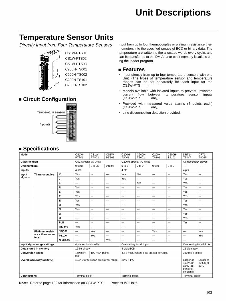
Unit Descriptions
103
Temperature Sensor UnitsDirectly Input from Four Temperature Sensors
CS1W-PTS01
CS1W-PTS02
CS1W-PTS03
C200H-TS001
C200H-TS002
C200H-TS101
C200H-TS102
Circuit Configuration
Temperature sensors
4 points
Input from up to four thermocouples or platinum resistance ther-mometers into the specified ranges of BCD or binary data. Thetemperature are written to the allocated words every cycle, andcan be transferred to the DM Area or other memory locations us-ing the ladder program.
Features• Input directly from up to four temperature sensors with one
Unit. (The types of temperature sensor and temperatureranges can be set separately for each input for theCS1W-PTS.)
• Models available with isolated inputs to prevent unwantedcurrent flow between temperature sensor inputs(CS1W-PTSonly).
• Provided with measured value alarms (4 points each)(CS1W-PTSonly).
• Line disconnection detection provided.
SpecificationsModel CS1W-
PTS01CS1W-PTS02
CS1W-PTS03
C200H-TS001
C200H-TS002
C200H-TS101
C200H-TS102
DRT1-TS04T
DRT1-TS04P
Classification CS1 Special I/O Units C200H Special I/O Units CompoBus/D Slaves
Unit numbers 0 to 95 0 to 95 0 to 95 0 to 9 0 to 9 0 to 9 0 to 9 --- ---
Inputs 4 pts 4 pts 4 pts
Inputi l
Thermocouples K Yes --- --- Yes Yes --- --- Yes ---Inputsignals
Thermocouples
J Yes --- --- Yes --- --- --- Yes ---
L --- --- --- --- Yes --- --- Yes ---
R Yes --- --- --- --- --- --- Yes ---
S Yes --- --- --- --- --- --- Yes ---
T Yes --- --- --- --- --- --- Yes ---
E Yes --- --- --- --- --- --- Yes ---
B Yes --- --- --- --- --- --- Yes ---
N Yes --- --- --- --- --- --- Yes ---
W --- --- --- --- --- --- --- Yes ---
U --- --- --- --- --- --- --- Yes ---
PLII --- --- --- --- --- --- --- Yes ---
±80 mV Yes --- --- --- --- --- --- --- ---
Platinum resist -th
JPt100 --- Yes --- --- --- Yes --- --- YesPlatinum resistance thermome -ters
PT100 --- Yes --- --- --- --- --- --- Yesters
Ni508.4Ω --- --- Yes --- --- --- --- --- ---
Input signal range settings 4 pts set individually One setting for all 4 pts One setting for all 4 pts
Data stored in memory 16-bit binary 4-digit BCD 16-bit binary
Conversion speed 150 ms/4pts
100 ms/4 points 4.8 s max. (when 4 pts are set for Unit). 250 ms/4 points
Overall accuracy (at 25 °C) ±0.1% for full span on internal range ±1% + 1°C Larger of±0.5% or±2°C (de-pendingon signal)
Larger of±0.5% or±1°C
Connections Terminal block Terminal block Terminal block
Note: Refer to page 102 for information on CS1W-PTS Process I/O Units.
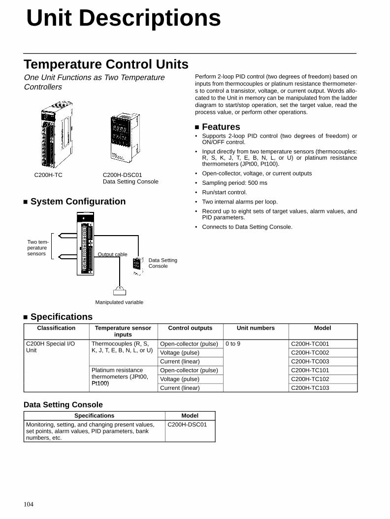
Unit Descriptions
104
Temperature Control UnitsOne Unit Functions as Two TemperatureControllers
C200H-TC C200H-DSC01Data Setting Console
System Configuration
Two tem-peraturesensors Output cable
Manipulated variable
Data SettingConsole
Perform 2-loop PID control (two degrees of freedom) based oninputs from thermocouples or platinum resistance thermometer-s to control a transistor, voltage, or current output. Words allo-cated to the Unit in memory can be manipulated from the ladderdiagram to start/stop operation, set the target value, read theprocess value, or perform other operations.
Features• Supports 2-loop PID control (two degrees of freedom) or
ON/OFF control.
• Input directly from two temperature sensors (thermocouples:R, S, K, J, T, E, B, N, L, or U) or platinum resistancethermometers (JPt00, Pt100).
• Open-collector, voltage, or current outputs
• Sampling period: 500 ms
• Run/start control.
• Two internal alarms per loop.
• Record up to eight sets of target values, alarm values, andPID parameters.
• Connects to Data Setting Console.
SpecificationsClassification Temperature sensor
inputsControl outputs Unit numbers Model
C200H Special I/OU i
Thermocouples (R, S,K J T E B N L U)
Open-collector (pulse) 0 to 9 C200H-TC001Unit
( , ,K, J, T, E, B, N, L, or U) Voltage (pulse) C200H-TC002
Current (linear) C200H-TC003
Platinum resistanceh (JP 00
Open-collector (pulse) C200H-TC101thermometers (JPt00,Pt100)
Voltage (pulse) C200H-TC102Pt100)
Current (linear) C200H-TC103
Data Setting ConsoleSpecifications Model
Monitoring, setting, and changing present values,set points, alarm values, PID parameters, banknumbers, etc.
C200H-DSC01
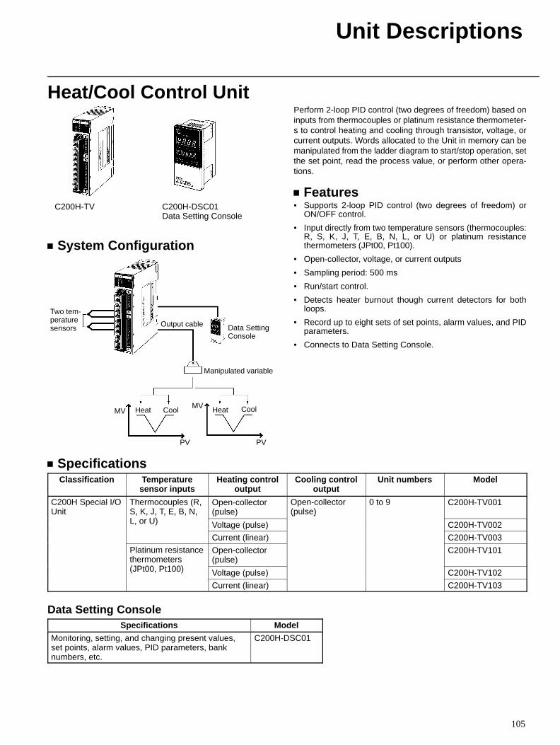
Unit Descriptions
105
Heat/Cool Control Unit
C200H-TV C200H-DSC01Data Setting Console
System Configuration
Two tem-peraturesensors Output cable
Manipulated variable
Data SettingConsole
Heat CoolMV
PV
Heat CoolMV
PV
Perform 2-loop PID control (two degrees of freedom) based oninputs from thermocouples or platinum resistance thermometer-s to control heating and cooling through transistor, voltage, orcurrent outputs. Words allocated to the Unit in memory can bemanipulated from the ladder diagram to start/stop operation, setthe set point, read the process value, or perform other opera-tions.
Features• Supports 2-loop PID control (two degrees of freedom) or
ON/OFF control.
• Input directly from two temperature sensors (thermocouples:R, S, K, J, T, E, B, N, L, or U) or platinum resistancethermometers (JPt00, Pt100).
• Open-collector, voltage, or current outputs
• Sampling period: 500 ms
• Run/start control.
• Detects heater burnout though current detectors for bothloops.
• Record up to eight sets of set points, alarm values, and PIDparameters.
• Connects to Data Setting Console.
SpecificationsClassification Temperature
sensor inputsHeating control
outputCooling control
outputUnit numbers Model
C200H Special I/OUnit
Thermocouples (R,S, K, J, T, E, B, N,L U)
Open-collector(pulse)
Open-collector(pulse)
0 to 9 C200H-TV001, , , , , , ,
L, or U) Voltage (pulse)
( )
C200H-TV002
Current (linear) C200H-TV003
Platinum resistancethermometers(JPt00 Pt100)
Open-collector(pulse)
C200H-TV101
(JPt00, Pt100) Voltage (pulse) C200H-TV102
Current (linear) C200H-TV103
Data Setting ConsoleSpecifications Model
Monitoring, setting, and changing present values,set points, alarm values, PID parameters, banknumbers, etc.
C200H-DSC01
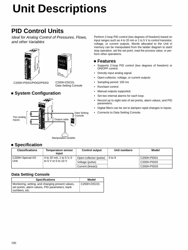
Unit Descriptions
106
PID Control UnitsIdeal for Analog Control of Pressures, Flows,and other Variables
C200H-PID01/PID02/PID03 C200H-DSC01Data Setting Console
System Configuration
Two analoginputs Output cable
Manipulated variable
Data SettingConsole
Perform 2-loop PID control (two degrees of freedom) based oninput ranges such as 4 to 20 mA or 1 to 5 V to control transistor,voltage, or current outputs. Words allocated to the Unit inmemory can be manipulated from the ladder diagram to start/stop operation, set the set point, read the process value, or per-form other operations.
Features• Supports 2-loop PID control (two degrees of freedom) or
ON/OFF control.
• Directly input analog signal.
• Open-collector, voltage, or current outputs
• Sampling period: 100 ms
• Run/start control.
• Manual outputs supported.
• Set two internal alarms for each loop.
• Record up to eight sets of set points, alarm values, and PIDparameters.
• Digital filters can be set to dampen rapid changes in inputs.
• Connects to Data Setting Console.
SpecificationClassifications Temperature sensor
inputControl output Unit numbers Model
C200H Special I/OU i
4 to 20 mA, 1 to 5 V, 05 V 0 10 V
Open-collector (pulse) 0 to 9 C200H-PID01Unit
, ,to 5 V or 0 to 10 V Voltage (pulse) C200H-PID02
Current (linear)) C200H-PID03
Data Setting ConsoleSpecifications Model
Monitoring, setting, and changing present values,set points, alarm values, PID parameters, banknumbers, etc.
C200H-DSC01
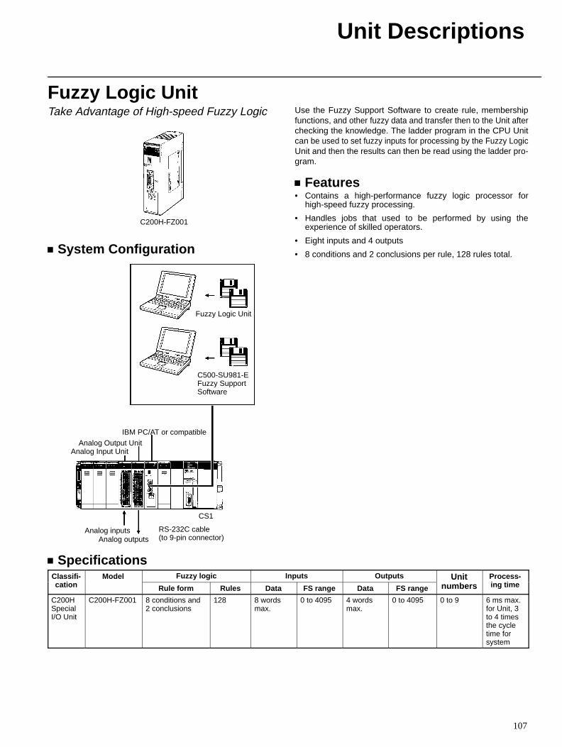
Unit Descriptions
107
Fuzzy Logic UnitTake Advantage of High-speed Fuzzy Logic
C200H-FZ001
System Configuration
Analog Output UnitAnalog Input Unit
Fuzzy Logic Unit
Analog inputsAnalog outputs
RS-232C cable (to 9-pin connector)
CS1
IBM PC/AT or compatible
C500-SU981-EFuzzy SupportSoftware
Use the Fuzzy Support Software to create rule, membershipfunctions, and other fuzzy data and transfer then to the Unit afterchecking the knowledge. The ladder program in the CPU Unitcan be used to set fuzzy inputs for processing by the Fuzzy LogicUnit and then the results can then be read using the ladder pro-gram.
Features• Contains a high-performance fuzzy logic processor for
high-speed fuzzy processing.
• Handles jobs that used to be performed by using theexperience of skilled operators.
• Eight inputs and 4 outputs
• 8 conditions and 2 conclusions per rule, 128 rules total.
SpecificationsClassifi-
tiModel Fuzzy logic Inputs Outputs Unit Process-
i tiC asscation
ode
Rule form Rules Data FS range Data FS range
Unitnumbers
ocessing time
C200HSpecialI/O Unit
C200H-FZ001 8 conditions and2 conclusions
128 8 wordsmax.
0 to 4095 4 wordsmax.
0 to 4095 0 to 9 6 ms max.for Unit, 3to 4 timesthe cycletime forsystem
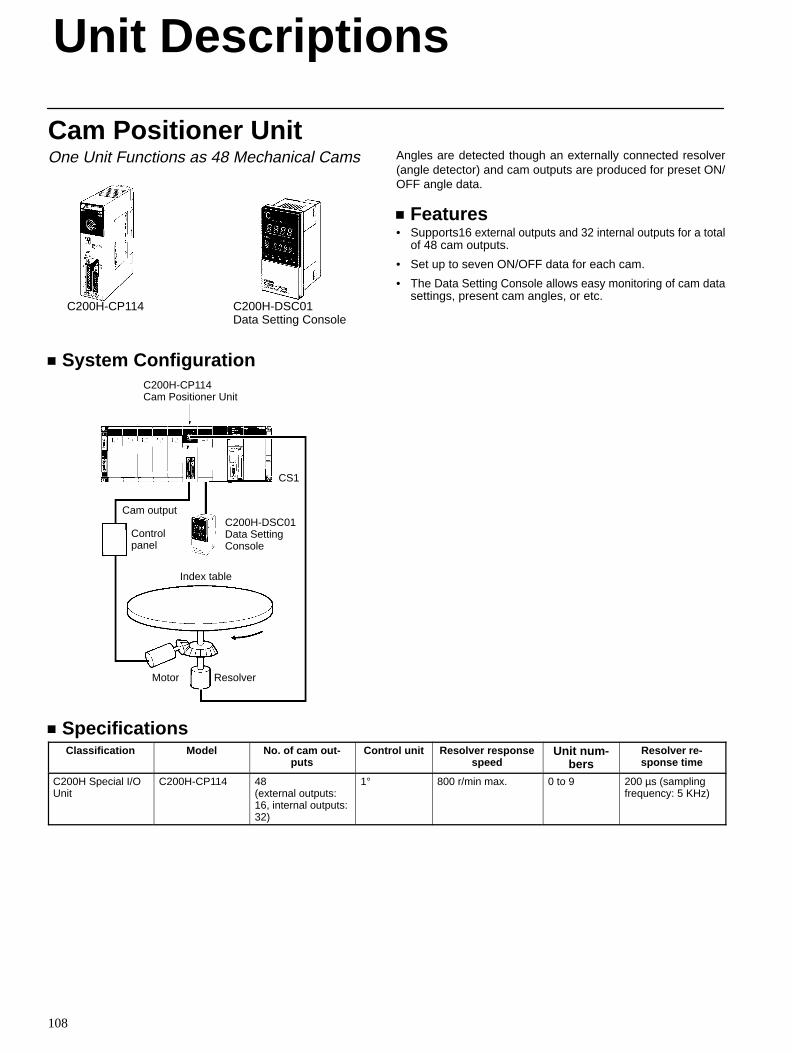
Unit Descriptions
108
Cam Positioner UnitOne Unit Functions as 48 Mechanical Cams
C200H-CP114 C200H-DSC01Data Setting Console
System ConfigurationC200H-CP114 Cam Positioner Unit
C200H-DSC01Data SettingConsole
CS1
Cam output
Controlpanel
Index table
Motor Resolver
Angles are detected though an externally connected resolver(angle detector) and cam outputs are produced for preset ON/OFF angle data.
Features• Supports16 external outputs and 32 internal outputs for a total
of 48 cam outputs.
• Set up to seven ON/OFF data for each cam.
• The Data Setting Console allows easy monitoring of cam datasettings, present cam angles, or etc.
SpecificationsClassification Model No. of cam out -
putsControl unit Resolver response
speedUnit num-
bersResolver re-sponse time
C200H Special I/OUnit
C200H-CP114 48 (external outputs:16, internal outputs:32)
1° 800 r/min max. 0 to 9 200 µs (samplingfrequency: 5 KHz)
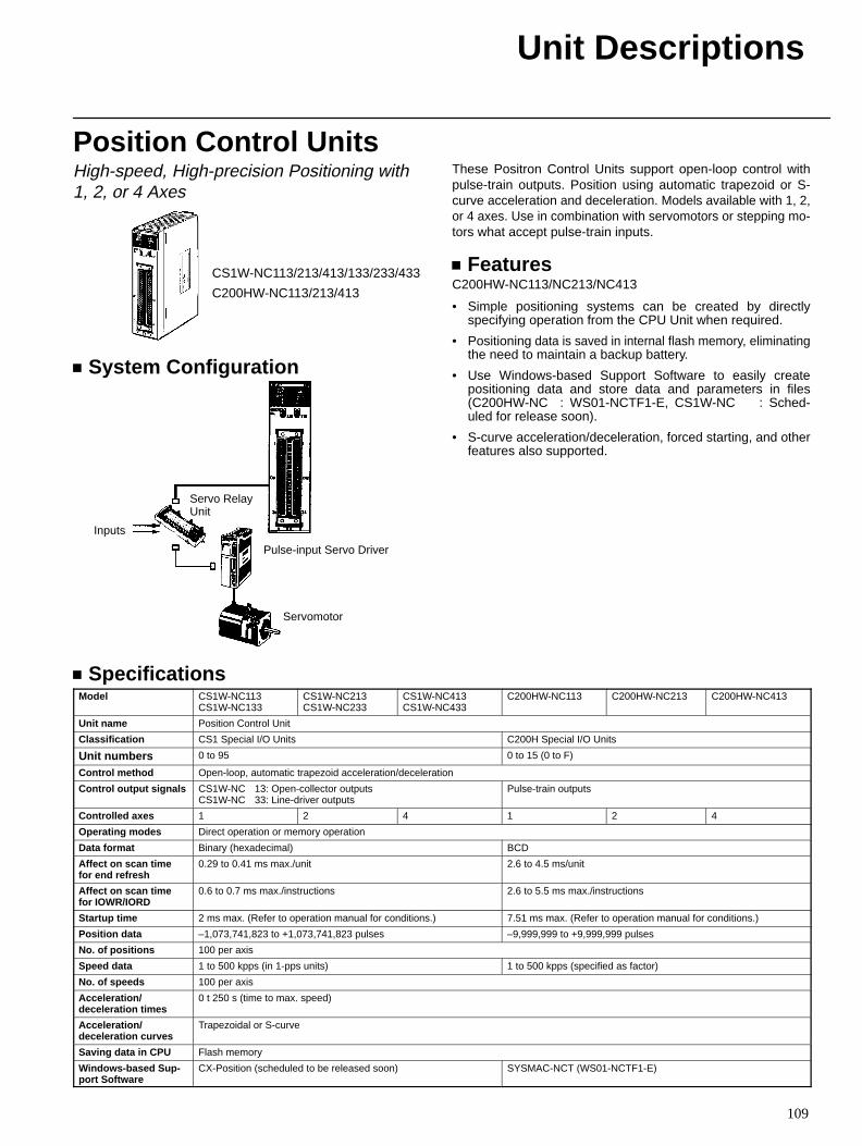
Unit Descriptions
109
Position Control UnitsHigh-speed, High-precision Positioning with 1, 2, or 4 Axes
CS1W-NC113/213/413/133/233/433
C200HW-NC113/213/413
System Configuration
Servo Relay Unit
Inputs
Pulse-input Servo Driver
Servomotor
These Positron Control Units support open-loop control withpulse-train outputs. Position using automatic trapezoid or S-curve acceleration and deceleration. Models available with 1, 2,or 4 axes. Use in combination with servomotors or stepping mo-tors what accept pulse-train inputs.
FeaturesC200HW-NC113/NC213/NC413
• Simple positioning systems can be created by directlyspecifying operation from the CPU Unit when required.
• Positioning data is saved in internal flash memory, eliminatingthe need to maintain a backup battery.
• Use Windows-based Support Software to easily createpositioning data and store data and parameters in files(C200HW-NC: WS01-NCTF1-E, CS1W-NC: Sched-uled for release soon).
• S-curve acceleration/deceleration, forced starting, and otherfeatures also supported.
SpecificationsModel CS1W-NC113
CS1W-NC133CS1W-NC213CS1W-NC233
CS1W-NC413CS1W-NC433
C200HW-NC113 C200HW-NC213 C200HW-NC413
Unit name Position Control Unit
Classification CS1 Special I/O Units C200H Special I/O Units
Unit numbers 0 to 95 0 to 15 (0 to F)
Control method Open-loop, automatic trapezoid acceleration/deceleration
Control output signals CS1W-NC13: Open-collector outputsCS1W-NC33: Line-driver outputs
Pulse-train outputs
Controlled axes 1 2 4 1 2 4
Operating modes Direct operation or memory operation
Data format Binary (hexadecimal) BCD
Affect on scan timefor end refresh
0.29 to 0.41 ms max./unit 2.6 to 4.5 ms/unit
Affect on scan timefor IOWR/IORD
0.6 to 0.7 ms max./instructions 2.6 to 5.5 ms max./instructions
Startup time 2 ms max. (Refer to operation manual for conditions.) 7.51 ms max. (Refer to operation manual for conditions.)
Position data –1,073,741,823 to +1,073,741,823 pulses –9,999,999 to +9,999,999 pulses
No. of positions 100 per axis
Speed data 1 to 500 kpps (in 1-pps units) 1 to 500 kpps (specified as factor)
No. of speeds 100 per axis
Acceleration/ deceleration times
0 t 250 s (time to max. speed)
Acceleration/deceleration curves
Trapezoidal or S-curve
Saving data in CPU Flash memory
Windows-based Sup -port Software
CX-Position (scheduled to be released soon) SYSMAC-NCT (WS01-NCTF1-E)
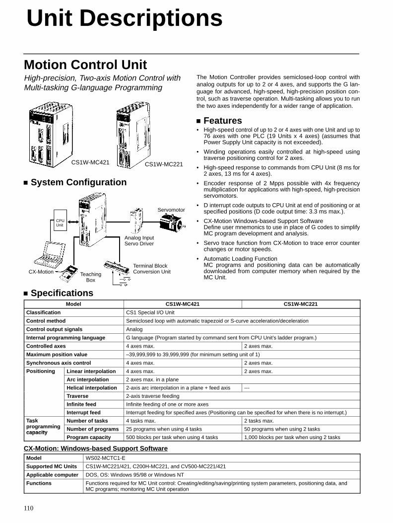
Unit Descriptions
110
Motion Control UnitHigh-precision, Two-axis Motion Control withMulti-tasking G-language Programming
CS1W-MC221CS1W-MC421
System Configuration
Servomotor
Analog InputServo Driver
Terminal BlockConversion UnitTeaching
Box
CX-Motion
CPUUnit
The Motion Controller provides semiclosed-loop control withanalog outputs for up to 2 or 4 axes, and supports the G lan-guage for advanced, high-speed, high-precision position con-trol, such as traverse operation. Multi-tasking allows you to runthe two axes independently for a wider range of application.
Features• High-speed control of up to 2 or 4 axes with one Unit and up to
76 axes with one PLC (19 Units x 4 axes) (assumes thatPower Supply Unit capacity is not exceeded).
• Winding operations easily controlled at high-speed usingtraverse positioning control for 2 axes.
• High-speed response to commands from CPU Unit (8 ms for2 axes, 13 ms for 4 axes).
• Encoder response of 2 Mpps possible with 4x frequencymultiplication for applications with high-speed, high-precisionservomotors.
• D interrupt code outputs to CPU Unit at end of positioning or atspecified positions (D code output time: 3.3 ms max.).
• CX-Motion Windows-based Support SoftwareDefine user mnemonics to use in place of G codes to simplifyMC program development and analysis.
• Servo trace function from CX-Motion to trace error counterchanges or motor speeds.
• Automatic Loading FunctionMC programs and positioning data can be automaticallydownloaded from computer memory when required by theMC Unit.
SpecificationsModel CS1W-MC421 CS1W-MC221
Classification CS1 Special I/O Unit
Control method Semiclosed loop with automatic trapezoid or S-curve acceleration/deceleration
Control output signals Analog
Internal programming language G language (Program started by command sent from CPU Unit’s ladder program.)
Controlled axes 4 axes max. 2 axes max.
Maximum position value –39,999,999 to 39,999,999 (for minimum setting unit of 1)
Synchronous axis control 4 axes max. 2 axes max.
Positioning Linear interpolation 4 axes max. 2 axes max.os o g
Arc interpolation 2 axes max. in a plane
Helical interpolation 2-axis arc interpolation in a plane + feed axis ---
Traverse 2-axis traverse feeding
Infinite feed Infinite feeding of one or more axes
Interrupt feed Interrupt feeding for specified axes (Positioning can be specified for when there is no interrupt.)
Taski
Number of tasks 4 tasks max. 2 tasks max.asprogrammingcapacity
Number of programs 25 programs when using 4 tasks 50 programs when using 2 taskscapac ity
Program capacity 500 blocks per task when using 4 tasks 1,000 blocks per task when using 2 tasks
CX-Motion: Windows-based Support SoftwareModel WS02-MCTC1-E
Supported MC Units CS1W-MC221/421, C200H-MC221, and CV500-MC221/421
Applicable computer DOS, OS: Windows 95/98 or Windows NT
Functions Functions required for MC Unit control: Creating/editing/saving/printing system parameters, positioning data, andMC programs; monitoring MC Unit operation
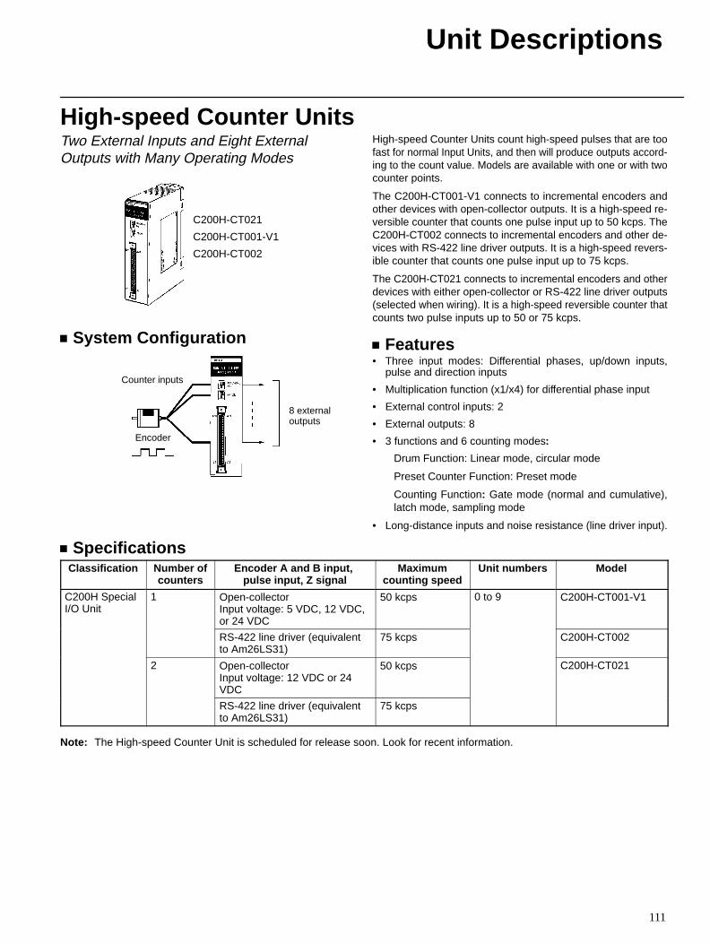
Unit Descriptions
111
High-speed Counter UnitsTwo External Inputs and Eight ExternalOutputs with Many Operating Modes
C200H-CT021
C200H-CT001-V1
C200H-CT002
System Configuration
Counter inputs
Encoder
8 externaloutputs
High-speed Counter Units count high-speed pulses that are toofast for normal Input Units, and then will produce outputs accord-ing to the count value. Models are available with one or with twocounter points.
The C200H-CT001-V1 connects to incremental encoders andother devices with open-collector outputs. It is a high-speed re-versible counter that counts one pulse input up to 50 kcps. TheC200H-CT002 connects to incremental encoders and other de-vices with RS-422 line driver outputs. It is a high-speed revers-ible counter that counts one pulse input up to 75 kcps.
The C200H-CT021 connects to incremental encoders and otherdevices with either open-collector or RS-422 line driver outputs(selected when wiring). It is a high-speed reversible counter thatcounts two pulse inputs up to 50 or 75 kcps.
Features• Three input modes: Differential phases, up/down inputs,
pulse and direction inputs
• Multiplication function (x1/x4) for differential phase input
• External control inputs: 2
• External outputs: 8
• 3 functions and 6 counting modes:
Drum Function: Linear mode, circular mode
Preset Counter Function: Preset mode
Counting Function: Gate mode (normal and cumulative),latch mode, sampling mode
• Long-distance inputs and noise resistance (line driver input).
SpecificationsClassification Number of
countersEncoder A and B input,
pulse input, Z signalMaximum
counting speedUnit numbers Model
C200H SpecialI/O Unit
1 Open-collectorInput voltage: 5 VDC, 12 VDC,or 24 VDC
50 kcps 0 to 9 C200H-CT001-V1
RS-422 line driver (equivalentto Am26LS31)
75 kcps C200H-CT002
2 Open-collectorInput voltage: 12 VDC or 24VDC
50 kcps C200H-CT021
RS-422 line driver (equivalentto Am26LS31)
75 kcps
Note: The High-speed Counter Unit is scheduled for release soon. Look for recent information.
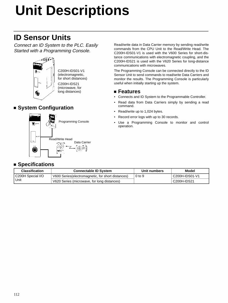
Unit Descriptions
112
ID Sensor UnitsConnect an ID System to the PLC. EasilyStarted with a Programming Console.
C200H-IDS01-V1(electromagnetic,for short distances)
C200H-IDS21(microwave, forlong distances)
System Configuration
Data CarrierRead/Write Head
Programming Console
Read/write data in Data Carrier memory by sending read/writecommands from the CPU Unit to the Read/Write Head. TheC200H-IDS01-V1 is used with the V600 Series for short-dis-tance communications with electromagnetic coupling, and theC200H-IDS21 is used with the V620 Series for long-distancecommunications with microwaves.
The Programming Console can be connected directly to the IDSensor Unit to send commands to read/write Data Carriers andmonitor the results. The Programming Console is particularlyuseful when initially starting up the system.
Features• Connects and ID System to the Programmable Controller.
• Read data from Data Carriers simply by sending a readcommand.
• Read/write up to 1,024 bytes.
• Record error logs with up to 30 records.
• Use a Programming Console to monitor and controloperation.
SpecificationsClassification Connectable ID System Unit numbers Model
C200H Special I/OU i
V600 Series(electromagnetic, for short distances) 0 to 9 C200H-IDS01-V1Unit V620 Series (microwave, for long distances) C200H-IDS21

Unit Descriptions
113
Serial Communications FeaturesUnit Model Ports Serial communications mode BASIC MessageU ode o s
Protocolmacros
HostLink
NT Links No-pro-tocol
Peripher-al bus
Program-ming
Consolebus
S Cprogram-
ming
essagecommu-nications
General-purposeexternaldevices
Hostcomput-
ers
OMRONPTs
General-purposeexternaldevices
Program-ming De -
vices
Program-ming
Console
CPUU it
Alld l
Port 1: Peripheral No Yes Yes No Yes Yes No NoC UUnits models Port 2: RS-232C No Yes Yes Yes Yes No No No
SerialC
CS1W-SCB21
Port 1: RS-232C Yes Yes Yes No No No No NoSe aCommu-nications
CSSCB21 Port 2: RS-232C Yes Yes Yes No No No No No
nicationsBoards/ CS1W-
SCB41Port 1: RS-232C Yes Yes Yes No No No No NoBoards/
UnitsCSSCB41 Port 2: RS-422A/485 Yes Yes Yes No No No No No
CS1W-SCU21
Port 1: RS-232C Yes Yes Yes No No No No NoCSSCU21 Port 2: RS-232C Yes Yes Yes No No No No No
ASCIIU it
C200H-ASC02
Port 1: RS-232C No No No No No No Yes NoSCUnits
C 00ASC02 Port 2: RS-232C No No No No No No Yes No
C200H-ASC11
Port 1: RS-232C No No No No No No Yes NoC 00ASC11 Port 2: RS-232C No No No No No No Yes No
C200H-ASC21
Port 1: RS-232C No No No No No No Yes NoC 00ASC21 Port 2: RS-422A/485 No No No No No No Yes No
C200H-ASC31
Port 1: RS-232C No No No No No No Yes NoC 00ASC31 Port 2: RS-232C No No No No No No Yes No
Compo-Bus/DRS-232CUnit
DRT1-232C2
Port 1: RS-232C
Port 2: RS-232C
No No No No No No No Yes
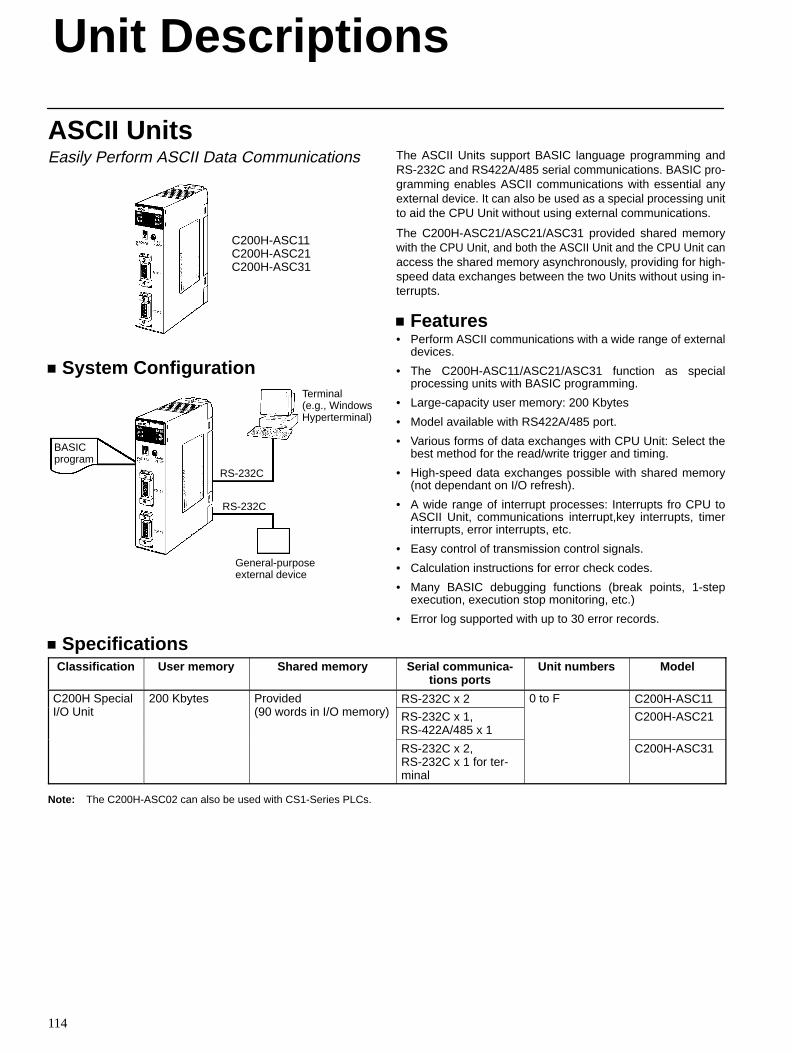
Unit Descriptions
114
ASCII UnitsEasily Perform ASCII Data Communications
C200H-ASC11C200H-ASC21C200H-ASC31
System Configuration
BASICprogram
RS-232C
RS-232C
General-purposeexternal device
Terminal(e.g., WindowsHyperterminal)
The ASCII Units support BASIC language programming andRS-232C and RS422A/485 serial communications. BASIC pro-gramming enables ASCII communications with essential anyexternal device. It can also be used as a special processing unitto aid the CPU Unit without using external communications.
The C200H-ASC21/ASC21/ASC31 provided shared memorywith the CPU Unit, and both the ASCII Unit and the CPU Unit canaccess the shared memory asynchronously, providing for high-speed data exchanges between the two Units without using in-terrupts.
Features• Perform ASCII communications with a wide range of external
devices.
• The C200H-ASC11/ASC21/ASC31 function as specialprocessing units with BASIC programming.
• Large-capacity user memory: 200 Kbytes
• Model available with RS422A/485 port.
• Various forms of data exchanges with CPU Unit: Select thebest method for the read/write trigger and timing.
• High-speed data exchanges possible with shared memory(not dependant on I/O refresh).
• A wide range of interrupt processes: Interrupts fro CPU toASCII Unit, communications interrupt,key interrupts, timerinterrupts, error interrupts, etc.
• Easy control of transmission control signals.
• Calculation instructions for error check codes.
• Many BASIC debugging functions (break points, 1-stepexecution, execution stop monitoring, etc.)
• Error log supported with up to 30 error records.
SpecificationsClassification User memory Shared memory Serial communica-
tions portsUnit numbers Model
C200H SpecialI/O U i
200 Kbytes Provided (90 d i I/O )
RS-232C x 2 0 to F C200H-ASC11I/O Unit
y(90 words in I/O memory) RS-232C x 1,
RS-422A/485 x 1C200H-ASC21
RS-232C x 2,RS-232C x 1 for ter-minal
C200H-ASC31
Note: The C200H-ASC02 can also be used with CS1-Series PLCs.
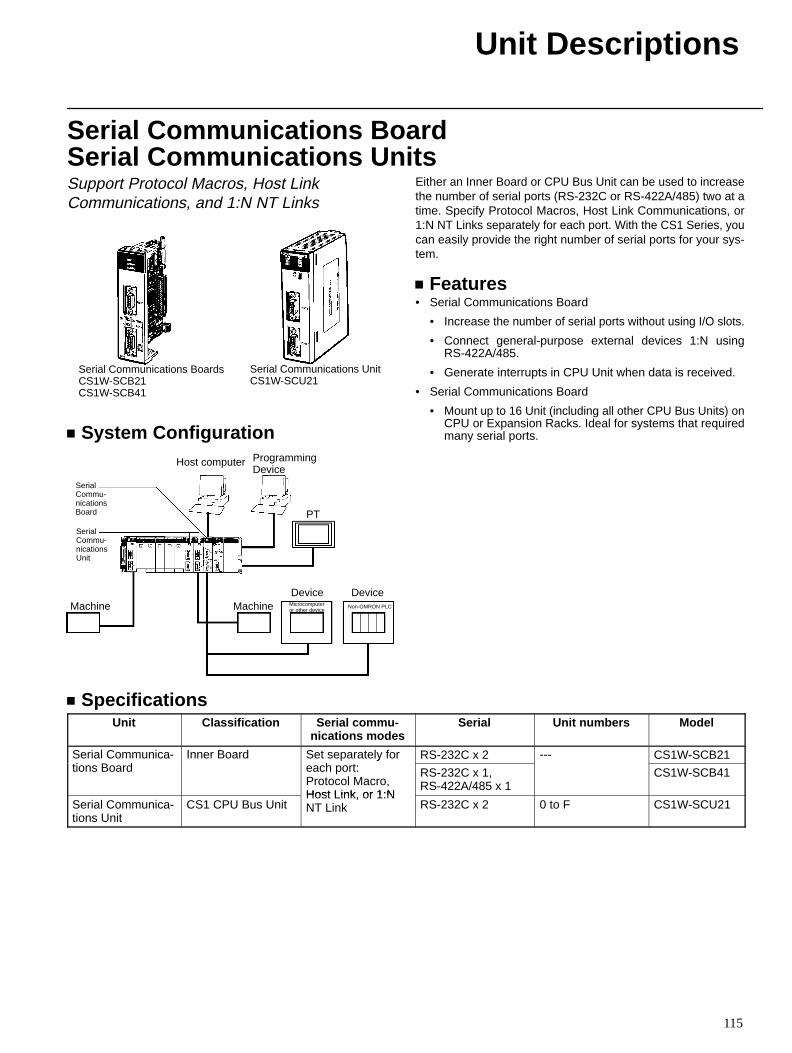
Unit Descriptions
115
Serial Communications Board Serial Communications UnitsSupport Protocol Macros, Host LinkCommunications, and 1:N NT Links
Serial Communications BoardsCS1W-SCB21CS1W-SCB41
Serial Communications UnitCS1W-SCU21
System Configuration
SerialCommu-nicationsBoard
SerialCommu-nicationsUnit
Host computer ProgrammingDevice
PT
Machine MachineDevice Device
Microcomputeror other device
Non-OMRON PLC
Either an Inner Board or CPU Bus Unit can be used to increasethe number of serial ports (RS-232C or RS-422A/485) two at atime. Specify Protocol Macros, Host Link Communications, or1:N NT Links separately for each port. With the CS1 Series, youcan easily provide the right number of serial ports for your sys-tem.
Features• Serial Communications Board
• Increase the number of serial ports without using I/O slots.
• Connect general-purpose external devices 1:N usingRS-422A/485.
• Generate interrupts in CPU Unit when data is received.
• Serial Communications Board
• Mount up to 16 Unit (including all other CPU Bus Units) onCPU or Expansion Racks. Ideal for systems that requiredmany serial ports.
SpecificationsUnit Classification Serial commu-
nications modesSerial Unit numbers Model
Serial Communica-i B d
Inner Board Set separately forh
RS-232C x 2 --- CS1W-SCB21tions Board
yeach port: Protocol Macro,Host Link or 1:N
RS-232C x 1,RS-422A/485 x 1
CS1W-SCB41
Serial Communica-tions Unit
CS1 CPU Bus UnitHost Link, or 1:NNT Link RS-232C x 2 0 to F CS1W-SCU21
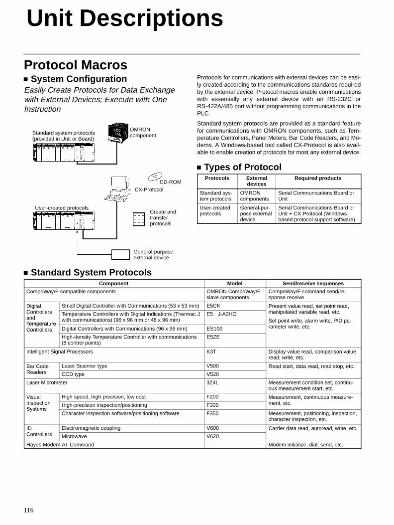
Unit Descriptions
116
Protocol Macros System Configuration
Easily Create Protocols for Data Exchangewith External Devices; Execute with OneInstruction
Standard system protocols(provided in Unit or Board)
OMRONcomponent
CX-ProtocolCD-ROM
Create andtransferprotocols
General-purposeexternal device
User-created protocols
Protocols for communications with external devices can be easi-ly created according to the communications standards requiredby the external device. Protocol macros enable communicationswith essentially any external device with an RS-232C orRS-422A/485 port without programming communications in thePLC.
Standard system protocols are provided as a standard featurefor communications with OMRON components, such as Tem-perature Controllers, Panel Meters, Bar Code Readers, and Mo-dems. A Windows-based tool called CX-Protocol is also avail-able to enable creation of protocols for most any external device.
Types of ProtocolProtocols External
devicesRequired products
Standard sys-tem protocols
OMRONcomponents
Serial Communications Board orUnit
User-createdprotocols
General-pur-pose externaldevice
Serial Communications Board orUnit + CX-Protocol (Windows-based protocol support software)
Standard System ProtocolsComponent Model Send/receive sequences
CompoWay/F-compatible components OMRON CompoWay/Fslave components
CompoWay/F command send/re-sponse receive
DigitalC t ll
Small Digital Controller with Communications (53 x 53 mm) E5CK Present value read, set point read,i l t d i bl d t
g aControllersandTemperature
Temperature Controllers with Digital Indications (Thermac Jwith communications) (96 x 96 mm or 48 x 96 mm)
E5J-A2HO
ese a ue ead, se o ead,manipulated variable read, etc.
Set point write, alarm write, PID pa-t it tTemperature
Controllers Digital Controllers with Communications (96 x 96 mm) ES100
Se o e, a a e, arameter write, etc.Controllers
High-density Temperature Controller with communications(8 control points)
E5ZE
Intelligent Signal Processors K3T Display value read, comparison valueread, write, etc.
Bar CodeR d
Laser Scanner type V500 Read start, data read, read stop, etc.a CodeReaders CCD type V520
ead s a , da a ead, ead s o , e c
Laser Micrometer 3Z4L Measurement condition set, continu-ous measurement start, etc.
VisualI ti
High speed, high precision, low cost F200 Measurement, continuous measure-t t
suaInspectionSystems
High-precision inspection/positioning F300
easu e e , co uous easu ement, etc.
SystemsCharacter inspection software/positioning software F350 Measurement, positioning, inspection,
character inspection, etc.
IDC t ll
Electromagnetic coupling V600 Carrier data read, autoread, write, etc.Controllers Microwave V620
Ca e da a ead, au o ead, e, e c
Hayes Modem AT Command --- Modem initialize, dial, send, etc.
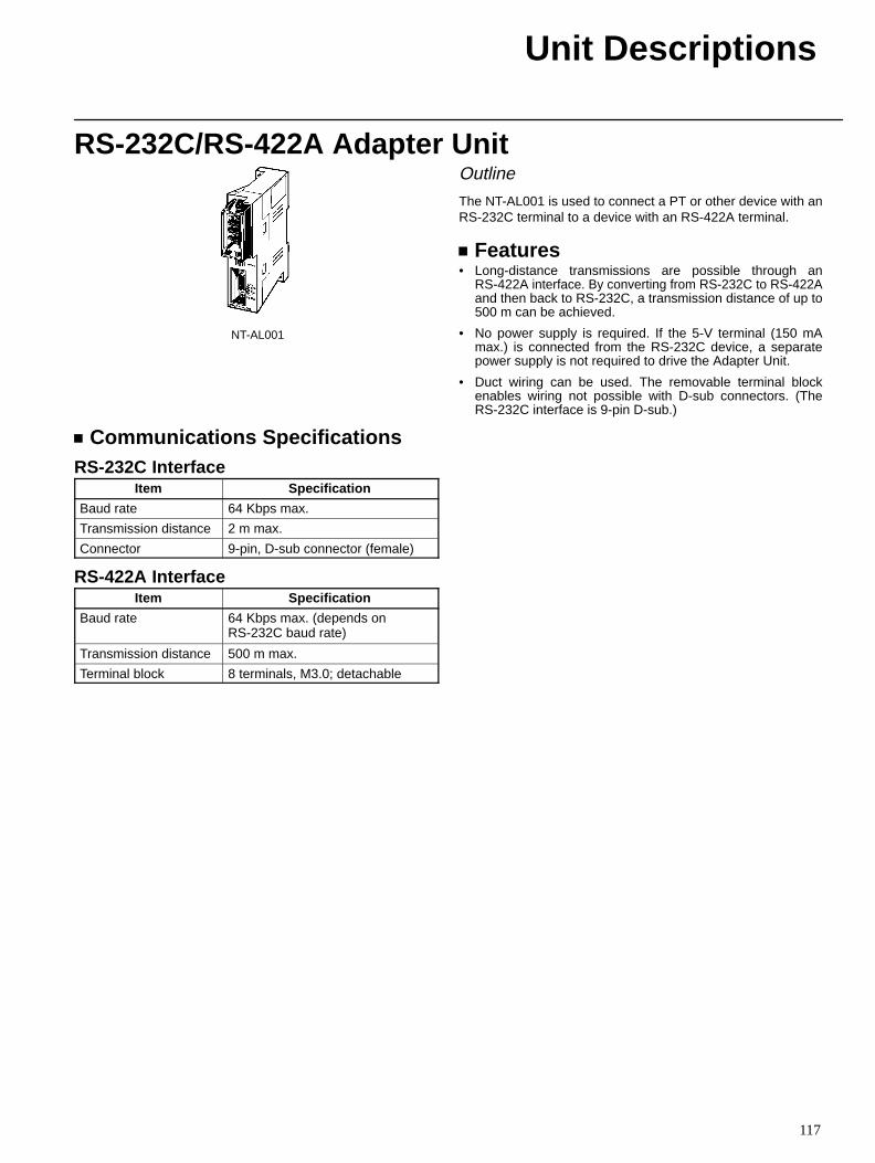
Unit Descriptions
117
RS-232C/RS-422A Adapter Unit
NT-AL001
Outline
The NT-AL001 is used to connect a PT or other device with anRS-232C terminal to a device with an RS-422A terminal.
Features• Long-distance transmissions are possible through an
RS-422A interface. By converting from RS-232C to RS-422Aand then back to RS-232C, a transmission distance of up to500 m can be achieved.
• No power supply is required. If the 5-V terminal (150 mAmax.) is connected from the RS-232C device, a separatepower supply is not required to drive the Adapter Unit.
• Duct wiring can be used. The removable terminal blockenables wiring not possible with D-sub connectors. (TheRS-232C interface is 9-pin D-sub.)
Communications SpecificationsRS-232C Interface
Item Specification
Baud rate 64 Kbps max.
Transmission distance 2 m max.
Connector 9-pin, D-sub connector (female)
RS-422A InterfaceItem Specification
Baud rate 64 Kbps max. (depends onRS-232C baud rate)
Transmission distance 500 m max.
Terminal block 8 terminals, M3.0; detachable
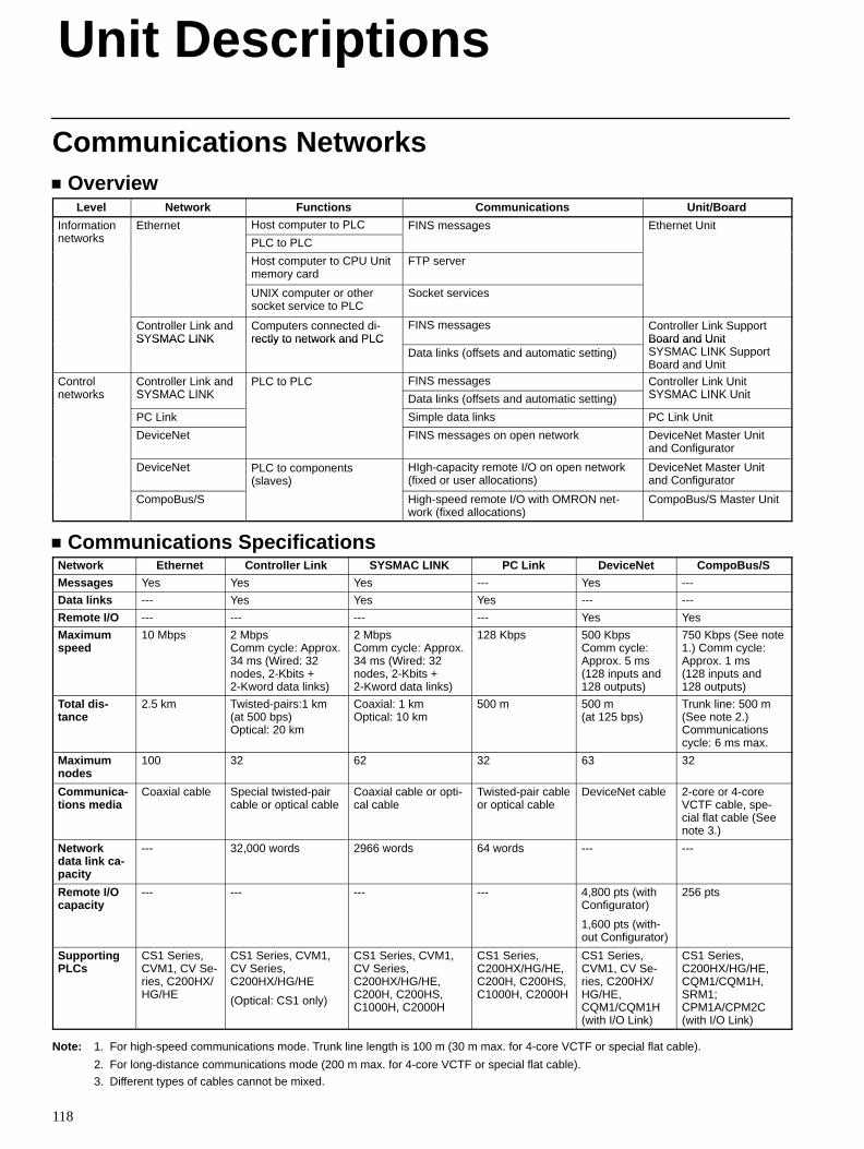
Unit Descriptions
118
Communications Networks Overview
Level Network Functions Communications Unit/Board
Informationt k
Ethernet Host computer to PLC FINS messages Ethernet Unito a onetworks
e e
PLC to PLC
S essages e e U
Host computer to CPU Unitmemory card
FTP server
UNIX computer or othersocket service to PLC
Socket services
Controller Link andSYSMAC LINK
Computers connected di-rectly to network and PLC
FINS messages Controller Link SupportBoard and UnitSYSMAC LINK rectly to network and PLC
Data links (offsets and automatic setting)Board and UnitSYSMAC LINK SupportBoard and Unit
Controlt k
Controller Link andSYSMAC LINK
PLC to PLC FINS messages Controller Link UnitSYSMAC LINK U it
Co onetworks
Co o e a dSYSMAC LINK
C o C
Data links (offsets and automatic setting)
Co o e USYSMAC LINK Unit
PC Link Simple data links PC Link Unit
DeviceNet FINS messages on open network DeviceNet Master Unitand Configurator
DeviceNet PLC to components(slaves)
HIgh-capacity remote I/O on open network(fixed or user allocations)
DeviceNet Master Unitand Configurator
CompoBus/S
( )
High-speed remote I/O with OMRON net-work (fixed allocations)
CompoBus/S Master Unit
Communications SpecificationsNetwork Ethernet Controller Link SYSMAC LINK PC Link DeviceNet CompoBus/S
Messages Yes Yes Yes --- Yes ---
Data links --- Yes Yes Yes --- ---
Remote I/O --- --- --- --- Yes Yes
Maximumspeed
10 Mbps 2 MbpsComm cycle: Approx.34 ms (Wired: 32nodes, 2-Kbits +2-Kword data links)
2 MbpsComm cycle: Approx.34 ms (Wired: 32nodes, 2-Kbits +2-Kword data links)
128 Kbps 500 Kbps Comm cycle: Approx. 5 ms(128 inputs and128 outputs)
750 Kbps (See note1.) Comm cycle: Approx. 1 ms(128 inputs and128 outputs)
Total dis -tance
2.5 km Twisted-pairs:1 km(at 500 bps)Optical: 20 km
Coaxial: 1 kmOptical: 10 km
500 m 500 m (at 125 bps)
Trunk line: 500 m(See note 2.)Communicationscycle: 6 ms max.
Maximumnodes
100 32 62 32 63 32
Communica-tions media
Coaxial cable Special twisted-paircable or optical cable
Coaxial cable or opti-cal cable
Twisted-pair cableor optical cable
DeviceNet cable 2-core or 4-coreVCTF cable, spe-cial flat cable (Seenote 3.)
Networkdata link ca -pacity
--- 32,000 words 2966 words 64 words --- ---
Remote I/Ocapacity
--- --- --- --- 4,800 pts (withConfigurator)
1,600 pts (with-out Configurator)
256 pts
SupportingPLCs
CS1 Series,CVM1, CV Se-ries, C200HX/HG/HE
CS1 Series, CVM1,CV Series, C200HX/HG/HE
(Optical: CS1 only)
CS1 Series, CVM1,CV Series, C200HX/HG/HE,C200H, C200HS,C1000H, C2000H
CS1 Series,C200HX/HG/HE,C200H, C200HS,C1000H, C2000H
CS1 Series,CVM1, CV Se-ries, C200HX/HG/HE,CQM1/CQM1H(with I/O Link)
CS1 Series,C200HX/HG/HE,CQM1/CQM1H,SRM1;CPM1A/CPM2C(with I/O Link)
Note: 1. For high-speed communications mode. Trunk line length is 100 m (30 m max. for 4-core VCTF or special flat cable).
2. For long-distance communications mode (200 m max. for 4-core VCTF or special flat cable).
3. Different types of cables cannot be mixed.
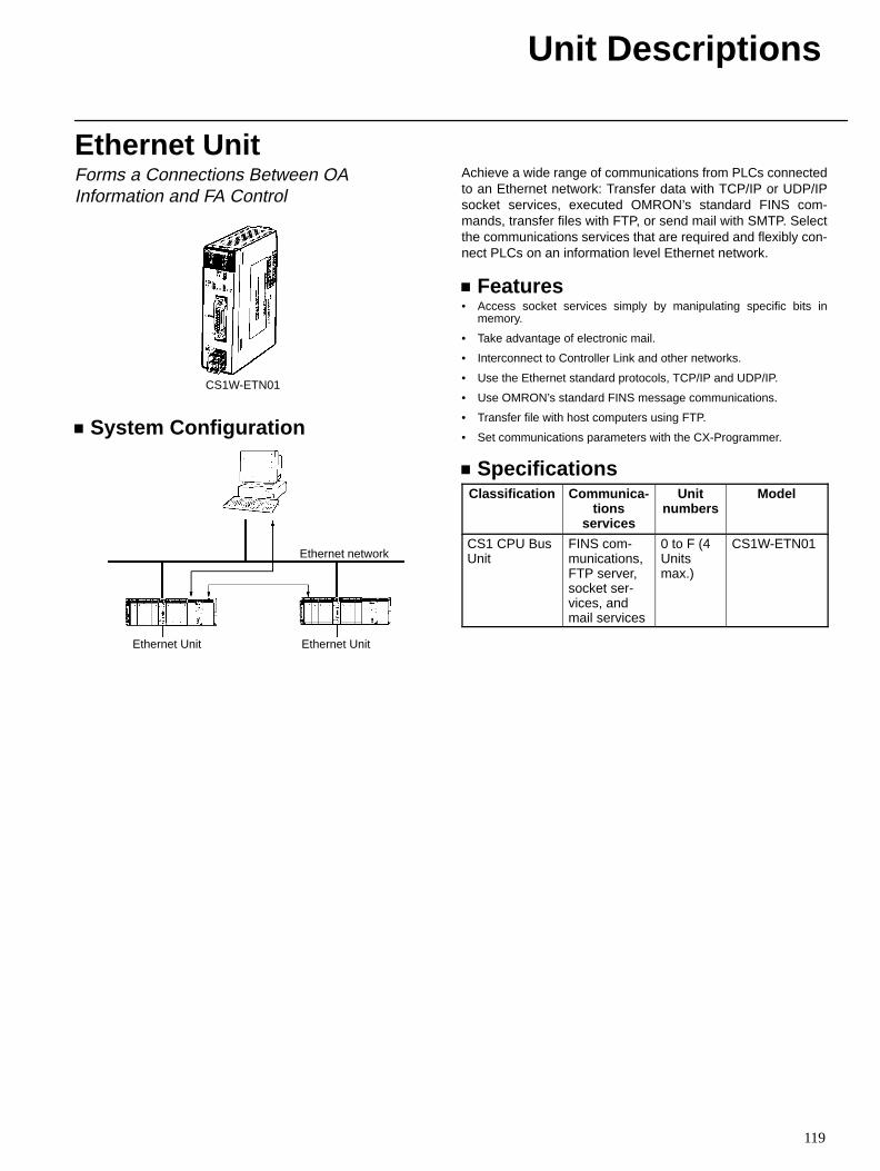
Unit Descriptions
119
Ethernet UnitForms a Connections Between OAInformation and FA Control
CS1W-ETN01
System Configuration
Ethernet network
Ethernet Unit Ethernet Unit
Achieve a wide range of communications from PLCs connectedto an Ethernet network: Transfer data with TCP/IP or UDP/IPsocket services, executed OMRON’s standard FINS com-mands, transfer files with FTP, or send mail with SMTP. Selectthe communications services that are required and flexibly con-nect PLCs on an information level Ethernet network.
Features• Access socket services simply by manipulating specific bits in
memory.
• Take advantage of electronic mail.
• Interconnect to Controller Link and other networks.
• Use the Ethernet standard protocols, TCP/IP and UDP/IP.
• Use OMRON’s standard FINS message communications.
• Transfer file with host computers using FTP.
• Set communications parameters with the CX-Programmer.
SpecificationsClassification Communica-
tionsservices
Unitnumbers
Model
CS1 CPU BusUnit
FINS com-munications,FTP server,socket ser-vices, andmail services
0 to F (4Unitsmax.)
CS1W-ETN01
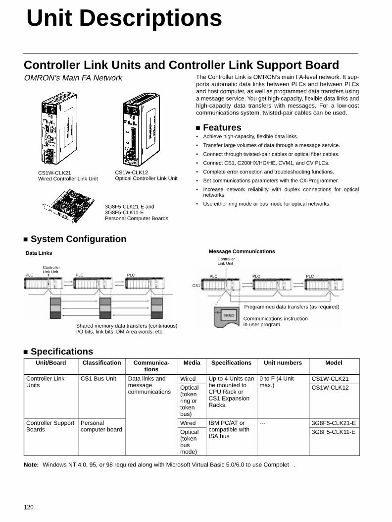
Unit Descriptions
120
Controller Link Units and Controller Link Support BoardOMRON’s Main FA Network
CS1W-CLK21Wired Controller Link Unit
CS1W-CLK12Optical Controller Link Unit
3G8F5-CLK21-E and3G8F5-CLK11-EPersonal Computer Boards
The Controller Link is OMRON’s main FA-level network. It sup-ports automatic data links between PLCs and between PLCsand host computer, as well as programmed data transfers usinga message service. You get high-capacity, flexible data links andhigh-capacity data transfers with messages. For a low-costcommunications system, twisted-pair cables can be used.
Features• Achieve high-capacity, flexible data links.
• Transfer large volumes of data through a message service.
• Connect through twisted-pair cables or optical fiber cables.
• Connect CS1, C200HX/HG/HE, CVM1, and CV PLCs.
• Complete error correction and troubleshooting functions.
• Set communications parameters with the CX-Programmer.
• Increase network reliability with duplex connections for opticalnetworks.
• Use either ring mode or bus mode for optical networks.
System Configuration
PLC
ControllerLink Unit
PLCPLC
Shared memory data transfers (continuous)I/O bits, link bits, DM Area words, etc.
Data Links
PLC
ControllerLink Unit
PLCPLC
Programmed data transfers (as required)
Message Communications
CS1
Communications instructionin user program
SpecificationsUnit/Board Classification Communica-
tionsMedia Specifications Unit numbers Model
Controller LinkU i
CS1 Bus Unit Data links and Wired Up to 4 Units canb d
0 to F (4 Unit)
CS1W-CLK21Units message
communicationsOptical(tokenring ortokenbus)
be mounted toCPU Rack orCS1 ExpansionRacks.
(max.) CS1W-CLK12
Controller SupportB d
Personalb d
Wired IBM PC/AT oribl i h
--- 3G8F5-CLK21-EBoards computer board Optical
(tokenbusmode)
compatible withISA bus
3G8F5-CLK11-E
Note: Windows NT 4.0, 95, or 98 required along with Microsoft Virtual Basic 5.0/6.0 to use Compolet.
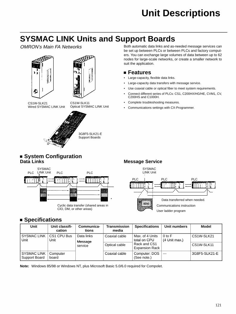
Unit Descriptions
121
SYSMAC LINK Units and Support BoardsOMRON’s Main FA Networks
CS1W-SLK21Wired SYSMAC LINK Unit
CS1W-SLK11Optical SYSMAC LINK Unit
3G8F5-SLK21-ESupport Boards
Both automatic data links and as-needed message services canbe set up between PLCs or between PLCs and factory comput-ers. You can exchange large volumes of data between up to 62nodes for large-scale networks, or create a smaller network tosuit the application.
Features• Large-capacity, flexible data links.
• Large-capacity data transfers with message service.
• Use coaxial cable or optical fiber to meet system requirements.
• Connect different series of PLCs: CS1, C200HX/HG/HE, CVM1, CV,C200HS and C1000H.
• Complete troubleshooting measures.
• Communications settings with CX-Programmer.
System ConfigurationData Links
PLC PLC PLC
Cyclic data transfer (shared areas inCIO, DM, or other areas)
*
SYSMACLINK Unit
Message Service
PLC PLC PLC
SYSMACLINK Unit
Data transferred when needed.
Communications instruction
User ladder program
SpecificationsUnit Unit classifi-
cationCommunica-
tionsTransmission
mediaSpecifications Unit numbers Model
SYSMAC LINKUnit
CS1 CPU BusUnit
Data links
Message
Coaxial cable Max. of 4 Unitstotal on CPU
0 to F (4 Unit max.)
CS1W-SLK21Unit Unit Message
service Optical cabletotal on CPURack and CS1Expansion Rack
(4 Unit max.)CS1W-SLK11
SYSMAC LINK Computer Coaxial cable Computer: DOS --- 3G8F5-SLK21-ESYSMAC LINKSupport Board
Com uterboard
Coaxial cable Com uter: DOS(See note.)
3G8F5 SLK21 E
Note: Windows 85/98 or Windows NT, plus Microsoft Basic 5.0/6.0 required for Compolet.
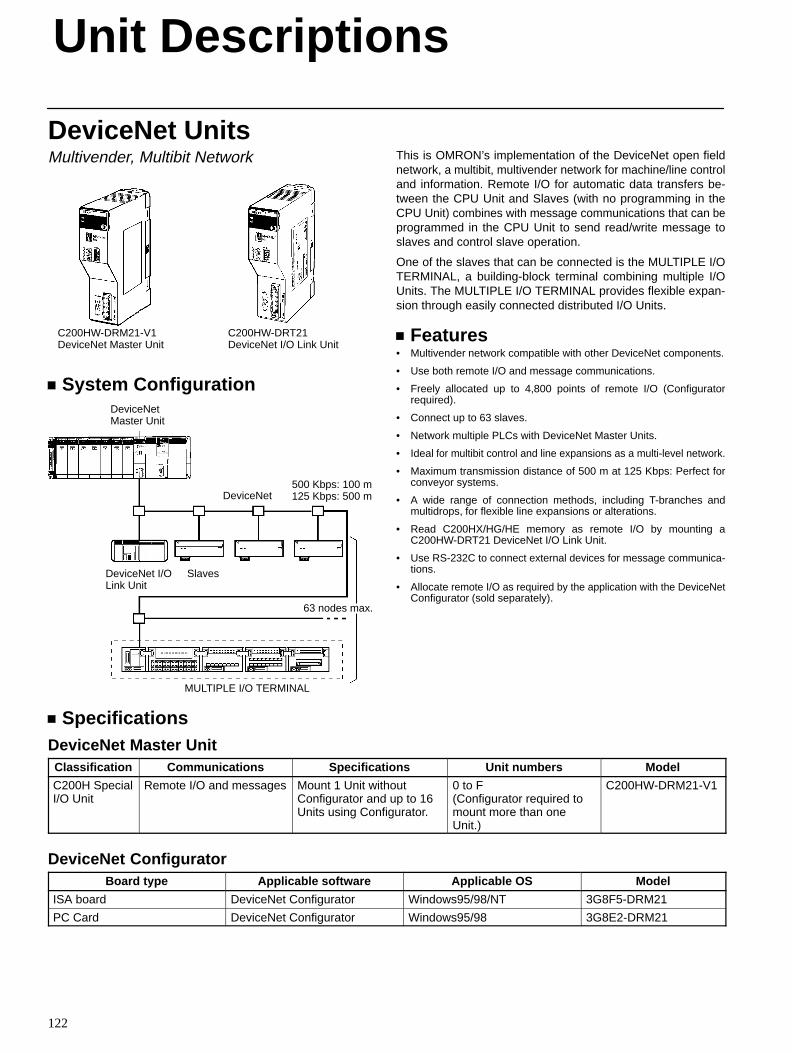
Unit Descriptions
122
DeviceNet UnitsMultivender, Multibit Network
C200HW-DRM21-V1DeviceNet Master Unit
C200HW-DRT21DeviceNet I/O Link Unit
System ConfigurationDeviceNetMaster Unit
DeviceNet I/OLink Unit
Slaves
63 nodes max.
500 Kbps: 100 m125 Kbps: 500 mDeviceNet
MULTIPLE I/O TERMINAL
This is OMRON’s implementation of the DeviceNet open fieldnetwork, a multibit, multivender network for machine/line controland information. Remote I/O for automatic data transfers be-tween the CPU Unit and Slaves (with no programming in theCPU Unit) combines with message communications that can beprogrammed in the CPU Unit to send read/write message toslaves and control slave operation.
One of the slaves that can be connected is the MULTIPLE I/OTERMINAL, a building-block terminal combining multiple I/OUnits. The MULTIPLE I/O TERMINAL provides flexible expan-sion through easily connected distributed I/O Units.
Features• Multivender network compatible with other DeviceNet components.
• Use both remote I/O and message communications.
• Freely allocated up to 4,800 points of remote I/O (Configuratorrequired).
• Connect up to 63 slaves.
• Network multiple PLCs with DeviceNet Master Units.
• Ideal for multibit control and line expansions as a multi-level network.
• Maximum transmission distance of 500 m at 125 Kbps: Perfect forconveyor systems.
• A wide range of connection methods, including T-branches andmultidrops, for flexible line expansions or alterations.
• Read C200HX/HG/HE memory as remote I/O by mounting aC200HW-DRT21 DeviceNet I/O Link Unit.
• Use RS-232C to connect external devices for message communica-tions.
• Allocate remote I/O as required by the application with the DeviceNetConfigurator (sold separately).
SpecificationsDeviceNet Master UnitClassification Communications Specifications Unit numbers Model
C200H SpecialI/O Unit
Remote I/O and messages Mount 1 Unit withoutConfigurator and up to 16Units using Configurator.
0 to F (Configurator required tomount more than oneUnit.)
C200HW-DRM21-V1
DeviceNet ConfiguratorBoard type Applicable software Applicable OS Model
ISA board DeviceNet Configurator Windows95/98/NT 3G8F5-DRM21
PC Card DeviceNet Configurator Windows95/98 3G8E2-DRM21
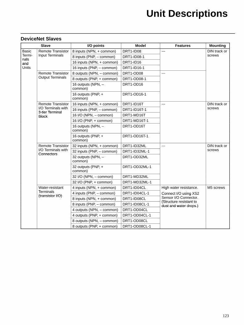
Unit Descriptions
123
DeviceNet SlavesSlave I/O points Model Features Mounting
BasicT i
Remote TransistorI T i l
8 inputs (NPN, + common) DRT1-ID08 --- DIN track orTermi-nals
Input Terminals 8 inputs (PNP, – common) DRT1-ID08-1 screwsnalsand 16 inputs (NPN, + common) DRT1-ID16andUnits 16 inputs (PNP, – common) DRT1-ID16-1
Remote TransistorO T i l
8 outputs (NPN, – common) DRT1-OD08 ---Output Terminals 8 outputs (PNP, + common) DRT1-OD08-1
16 outputs (NPN, –common)
DRT1-OD16
16 outputs (PNP, +common)
DRT1-OD16-1
Remote TransistorI/O T i l i h
16 inputs (NPN, + common) DRT1-ID16T --- DIN track orI/O Terminals with3-tier Terminal
16 inputs (PNP, – common) DRT1-ID16T-1 screws3-tier TerminalBlock 16 I/O (NPN, – common) DRT1-MD16TBlock
16 I/O (PNP, + common) DRT1-MD16T-1
16 outputs (NPN, –common)
DRT1-OD16T
16 outputs (PNP, +common)
DRT1-OD16T-1
Remote TransistorI/O T i l i h
32 inputs (NPN, + common) DRT1-ID32ML --- DIN track orI/O Terminals withConnectors
32 inputs (PNP, – common) DRT1-ID32ML-1 screwsConnectors
32 outputs (NPN, –common)
DRT1-OD32ML
32 outputs (PNP, +common)
DRT1-OD32ML-1
32 I/O (NPN, – common) DRT1-MD32ML
32 I/O (PNP, + common) DRT1-MD32ML-1
Water-resistantT i l
4 inputs (NPN, + common) DRT1-ID04CL High water resistance. M5 screwsTerminals(transistor I/O)
4 inputs (PNP, – common) DRT1-ID04CL-1
g
Connect I/O using XS2(transistor I/O)
8 inputs (NPN, + common) DRT1-ID08CLConnect I/O using XS2Sensor I/O Connector.(Structure resistant to
8 inputs (PNP, – common) DRT1-ID08CL-1(Structure resistant todust and water drops.)
4 outputs (NPN, – common) DRT1-OD04CLdust and water dro s.)
4 outputs (PNP, + common) DRT1-OD04CL-1
8 outputs (NPN, – common) DRT1-OD08CL
8 outputs (PNP, + common) DRT1-OD08CL-1
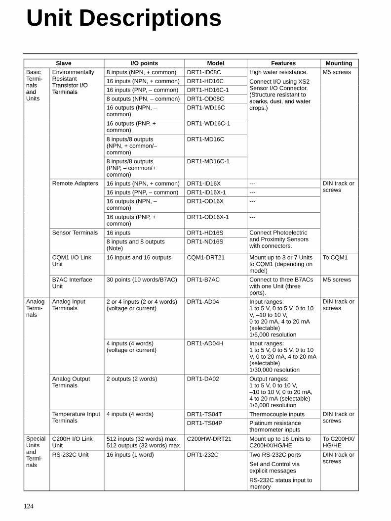
Unit Descriptions
124
Slave MountingFeaturesModelI/O points
BasicT i
EnvironmentallyR i
8 inputs (NPN, + common) DRT1-ID08C High water resistance. M5 screwsTermi-nals
yResistantTransistor I/O
16 inputs (NPN, + common) DRT1-HD16C
g
Connect I/O using XS2nalsand
Transistor I/OTerminals 16 inputs (PNP, – common) DRT1-HD16C-1
Connect I/O using XS2Sensor I/O Connector.(Structure resistant toand
UnitsTerminals
8 outputs (NPN, – common) DRT1-OD08C(Structure resistant tosparks, dust, and water
16 outputs (NPN, –common)
DRT1-WD16Cs arks, dust, and waterdrops.)
16 outputs (PNP, +common)
DRT1-WD16C-1
8 inputs/8 outputs(NPN, + common/–common)
DRT1-MD16C
8 inputs/8 outputs(PNP, – common/+common)
DRT1-MD16C-1
Remote Adapters 16 inputs (NPN, + common) DRT1-ID16X --- DIN track or
16 inputs (PNP, – common) DRT1-ID16X-1 --- screws
16 outputs (NPN, –common)
DRT1-OD16X ---
16 outputs (PNP, +common)
DRT1-OD16X-1 ---
Sensor Terminals 16 inputs DRT1-HD16S Connect Photoelectricd P i i S8 inputs and 8 outputs
(Note)DRT1-ND16S and Proximity Sensors
with connectors.
CQM1 I/O LinkUnit
16 inputs and 16 outputs CQM1-DRT21 Mount up to 3 or 7 Unitsto CQM1 (depending onmodel)
To CQM1
B7AC InterfaceUnit
30 points (10 words/B7AC) DRT1-B7AC Connect to three B7ACswith one Unit (threeports).
M5 screws
AnalogTermi-nals
Analog InputTerminals
2 or 4 inputs (2 or 4 words)(voltage or current)
DRT1-AD04 Input ranges: 1 to 5 V, 0 to 5 V, 0 to 10V, –10 to 10 V,0 to 20 mA, 4 to 20 mA(selectable)1/6,000 resolution
DIN track orscrews
4 inputs (4 words)(voltage or current)
DRT1-AD04H Input ranges: 1 to 5 V, 0 to 5 V, 0 to 10V, 0 to 20 mA, 4 to 20 mA(selectable)1/30,000 resolution
Analog OutputTerminals
2 outputs (2 words) DRT1-DA02 Output ranges: 1 to 5 V, 0 to 10 V,–10 to 10 V, 0 to 20 mA,4 to 20 mA (selectable)1/6,000 resolution
Temperature InputT i l
4 inputs (4 words) DRT1-TS04T Thermocouple inputs DIN track orTerminals
( )
DRT1-TS04P Platinum resistancethermometer inputs
screws
SpecialUnits
d
C200H I/O LinkUnit
512 inputs (32 words) max.512 outputs (32 words) max.
C200HW-DRT21 Mount up to 16 Units toC200HX/HG/HE
To C200HX/HG/HE
andTermi-nals
RS-232C Unit 16 inputs (1 word) DRT1-232C Two RS-232C ports
Set and Control viaexplicit messages
RS-232C status input tomemory
DIN track orscrews
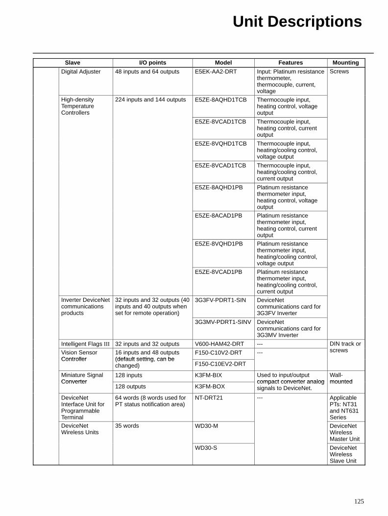
Unit Descriptions
125
Slave MountingFeaturesModelI/O points
Digital Adjuster 48 inputs and 64 outputs E5EK-AA2-DRT Input: Platinum resistancethermometer,thermocouple, current,voltage
Screws
High-densityTemperatureControllers
224 inputs and 144 outputs E5ZE-8AQHD1TCB Thermocouple input,heating control, voltageoutput
E5ZE-8VCAD1TCB Thermocouple input,heating control, currentoutput
E5ZE-8VQHD1TCB Thermocouple input,heating/cooling control,voltage output
E5ZE-8VCAD1TCB Thermocouple input,heating/cooling control,current output
E5ZE-8AQHD1PB Platinum resistancethermometer input,heating control, voltageoutput
E5ZE-8ACAD1PB Platinum resistancethermometer input,heating control, currentoutput
E5ZE-8VQHD1PB Platinum resistancethermometer input,heating/cooling control,voltage output
E5ZE-8VCAD1PB Platinum resistancethermometer input,heating/cooling control,current output
Inverter DeviceNetcommunicationsproducts
32 inputs and 32 outputs (40inputs and 40 outputs whenset for remote operation)
3G3FV-PDRT1-SIN DeviceNetcommunications card for3G3FV Inverter)
3G3MV-PDRT1-SINV DeviceNetcommunications card for3G3MV Inverter
Intelligent Flags III 32 inputs and 32 outputs V600-HAM42-DRT --- DIN track or
Vision SensorController
16 inputs and 48 outputs(default setting can be
F150-C10V2-DRT --- screws
Controller (default setting, can bechanged) F150-C10EV2-DRT
Miniature SignalConverter
128 inputs K3FM-BIX Used to input/outputcompact converter analog
Wall-mountedConverter
128 outputs K3FM-BOXcompact converter analogsignals to DeviceNet.
mounted
DeviceNetInterface Unit forProgrammableTerminal
64 words (8 words used forPT status notification area)
NT-DRT21 --- ApplicablePTs: NT31and NT631Series
DeviceNetWireless Units
35 words WD30-M DeviceNetWirelessMaster Unit
WD30-S DeviceNetWirelessSlave Unit
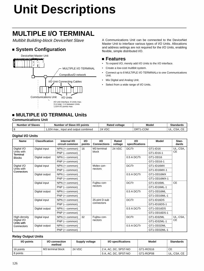
Unit Descriptions
126
MULTIPLE I/O TERMINALMultibit Building-block DeviceNet Slave
System ConfigurationDeviceNet Master Unit
MULTIPLE I/O TERMINAL
CompoBus/D network
I/O Unit Connecting Cables
Communications Unit I/O Units
I/O Unit Interface: 8 Units max. 3 m total, 1 m between Units1,024 I/O points max.
A Communications Unit can be connected to the DeviceNetMaster Unit to interface various types of I/O Units. Allocationsand address settings are not required for the I/O Units, enablingflexible, simple distributed I/O.
Features• To expand I/O, merely add I/O Units to the I/O interface.
• Create a low-cost multibit system.
• Connect up to 8 MULTIPLE I/O TERMINALs to one CommunicationsUnit.
• Mix Digital and Analog Unit.
• Select from a wide range of I/O Units.
MULTIPLE I/O TERMINAL UnitsCommunications Unit
Number of Slaves Number of Slave I/O points Rated voltage Model Standards
8 1,024 max., input and output combined 24 VDC DRT1-COM UL, CSA, CE
Digital I/O UnitsName Classification Internal I/O
circuit commonI/O
pointsI/O
ConnectionsRated
voltageI/O
specificationsModel Stan-
dards
Digital I/OU it ith
Digital input NPN (+ common) 16 M3 terminalbl k
24 VDC DC/Tr GT1-ID16 UL, CSA,CE
g a /OUnits withTerminal
PNP (– common)
3 e ablock GT1-ID16-1
U , CS ,CE
TerminalBlocks Digital output NPN (– common) 0.5 A DC/Tr GT1-OD16Blocks
PNP (+ common) GT1-OD16-1
Digital I/OU it ith
Digital input NPN (+ common) Molex con-t
DC/Tr GT1-ID16MXg a /OUnits withConnectors
PNP (– common)
o e conectors GT1-ID16MX-1
ConnectorsDigital output NPN (– common) 0.5 A DC/Tr GT1-OD16MX
PNP (+ common) GT1-OD16MX-1
Digital input NPN (+ common) Fujitsu con-t
DC/Tr GT1-ID16ML CE
PNP (– common)
uj su conectors GT1-ID16ML-1
C
Digital output NPN (– common) 0.5 A DC/Tr GT1-OD16ML
PNP (+ common) GT1-OD16ML-1
Digital input NPN (+ common) 25-pint D-subt
DC/Tr GT1-ID16DS
PNP (– common)
5 subconnectors GT1-ID16DS-1
Digital output NPN (– common) 0.5 A DC/Tr GT1-OD16DS
PNP (+ common) GT1-OD16DS-1
High-densityDi it l I/O
Digital input NPN (+ common) 32 Fujitsu con-t
DC/Tr GT1-ID32ML UL, CSA,CE
g de s yDigital I/OUnits with
PNP (– common)
uj su conectors GT1-ID32ML-1
U , CS ,CE
Units withConnectors Digital output NPN (– common) 0.5 A DC/Tr GT1-OD32MLConnectors
PNP (+ common) GT1-OD32ML-1
Relay Output UnitsI/O points I/O connection
methodSupply voltage I/O specifications Model Standards
16 points M3 terminal block 24 VDC 2 A, AC, DC, SPST-NO GT1-ROS16 CE8 points
3 e a b oc
5 A, AC, DC, SPST-NO GT1-ROP08 UL, CSA, CE
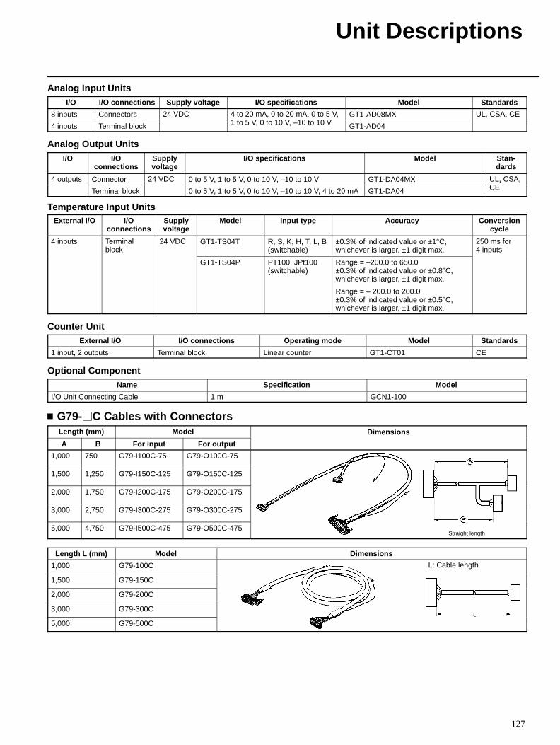
Unit Descriptions
127
Analog Input UnitsI/O I/O connections Supply voltage I/O specifications Model Standards
8 inputs Connectors 24 VDC 4 to 20 mA, 0 to 20 mA, 0 to 5 V,1 t 5 V 0 t 10 V 10 t 10 V
GT1-AD08MX UL, CSA, CE
4 inputs Terminal block
C o 0 , 0 o 0 , 0 o 5 ,1 to 5 V, 0 to 10 V, –10 to 10 V GT1-AD04
U , CS , C
Analog Output UnitsI/O I/O
connectionsSupplyvoltage
I/O specifications Model Stan-dards
4 outputs Connector 24 VDC 0 to 5 V, 1 to 5 V, 0 to 10 V, –10 to 10 V GT1-DA04MX UL, CSA,CE
ou u s
Terminal block
C
0 to 5 V, 1 to 5 V, 0 to 10 V, –10 to 10 V, 4 to 20 mA GT1-DA04
U , CS ,CE
Temperature Input UnitsExternal I/O I/O
connectionsSupplyvoltage
Model Input type Accuracy Conversioncycle
4 inputs Terminalblock
24 VDC GT1-TS04T R, S, K, H, T, L, B(switchable)
±0.3% of indicated value or ±1°C,whichever is larger, ±1 digit max.
250 ms for4 inputs
GT1-TS04P PT100, JPt100(switchable)
Range = –200.0 to 650.0 ±0.3% of indicated value or ±0.8°C,whichever is larger, ±1 digit max.
Range = – 200.0 to 200.0 ±0.3% of indicated value or ±0.5°C,whichever is larger, ±1 digit max.
Counter UnitExternal I/O I/O connections Operating mode Model Standards
1 input, 2 outputs Terminal block Linear counter GT1-CT01 CE
Optional ComponentName Specification Model
I/O Unit Connecting Cable 1 m GCN1-100
G79-C Cables with ConnectorsLength (mm) Model Dimensions
A B For input For output
e s o s
1,000 750 G79-I100C-75 G79-O100C-75
1,500 1,250 G79-I150C-125 G79-O150C-125
2,000 1,750 G79-I200C-175 G79-O200C-175
3,000 2,750 G79-I300C-275 G79-O300C-275
5,000 4,750 G79-I500C-475 G79-O500C-475Straight length
Length L (mm) Model Dimensions
1,000 G79-100C L: Cable length
1,500 G79-150C
2,000 G79-200C
3,000 G79-300C
5,000 G79-500C
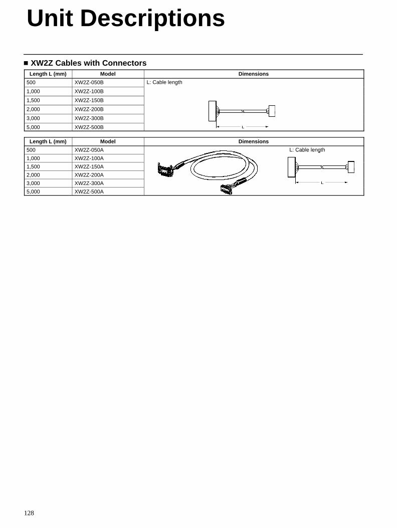
Unit Descriptions
128
XW2Z Cables with ConnectorsLength L (mm) Model Dimensions
500 XW2Z-050B L: Cable length
1,000 XW2Z-100B
g
1,500 XW2Z-150B
2,000 XW2Z-200B
3,000 XW2Z-300B
5,000 XW2Z-500B
Length L (mm) Model Dimensions
500 XW2Z-050A L: Cable length
1,000 XW2Z-100A
Cab e e g
1,500 XW2Z-150A
2,000 XW2Z-200A
3,000 XW2Z-300A
5,000 XW2Z-500A
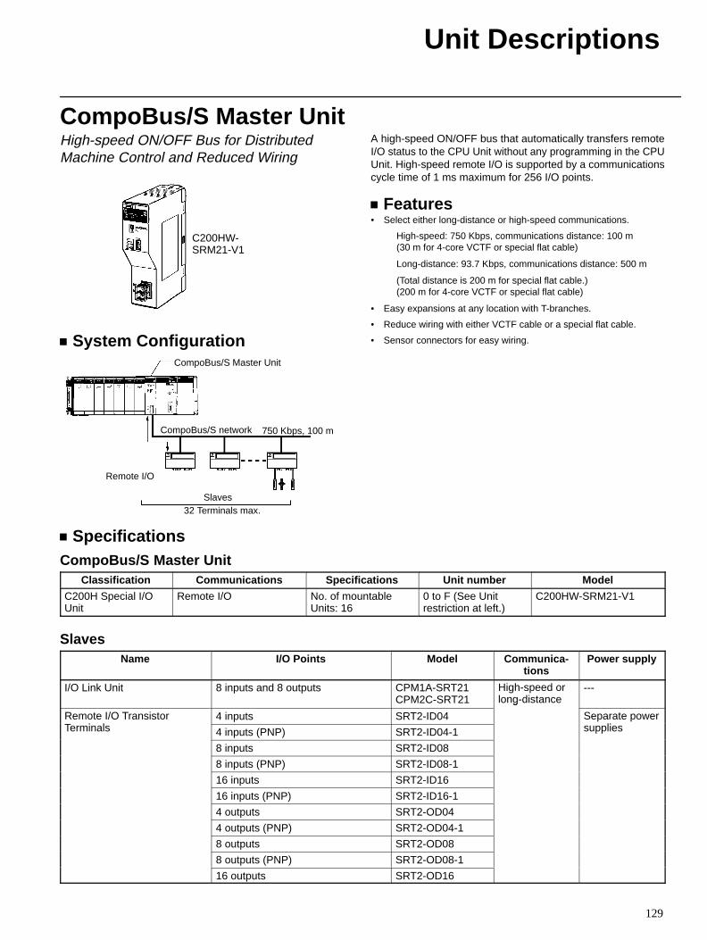
Unit Descriptions
129
CompoBus/S Master UnitHigh-speed ON/OFF Bus for DistributedMachine Control and Reduced Wiring
C200HW-SRM21-V1
System ConfigurationCompoBus/S Master Unit
CompoBus/S network
Slaves32 Terminals max.
Remote I/O
750 Kbps, 100 m
A high-speed ON/OFF bus that automatically transfers remoteI/O status to the CPU Unit without any programming in the CPUUnit. High-speed remote I/O is supported by a communicationscycle time of 1 ms maximum for 256 I/O points.
Features• Select either long-distance or high-speed communications.
High-speed: 750 Kbps, communications distance: 100 m(30 m for 4-core VCTF or special flat cable)
Long-distance: 93.7 Kbps, communications distance: 500 m
(Total distance is 200 m for special flat cable.)(200 m for 4-core VCTF or special flat cable)
• Easy expansions at any location with T-branches.
• Reduce wiring with either VCTF cable or a special flat cable.
• Sensor connectors for easy wiring.
SpecificationsCompoBus/S Master Unit
Classification Communications Specifications Unit number Model
C200H Special I/OUnit
Remote I/O No. of mountableUnits: 16
0 to F (See Unitrestriction at left.)
C200HW-SRM21-V1
SlavesName I/O Points Model Communica-
tionsPower supply
I/O Link Unit 8 inputs and 8 outputs CPM1A-SRT21CPM2C-SRT21
High-speed orlong-distance
---
Remote I/O TransistorT i l
4 inputs SRT2-ID04
g
Separate powerliTerminals 4 inputs (PNP) SRT2-ID04-1 supplies
8 inputs SRT2-ID08
8 inputs (PNP) SRT2-ID08-1
16 inputs SRT2-ID16
16 inputs (PNP) SRT2-ID16-1
4 outputs SRT2-OD04
4 outputs (PNP) SRT2-OD04-1
8 outputs SRT2-OD08
8 outputs (PNP) SRT2-OD08-1
16 outputs SRT2-OD16
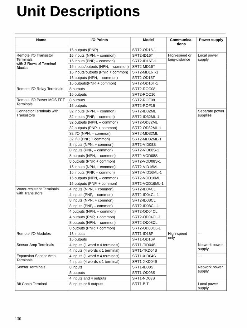
Unit Descriptions
130
Name Power supplyCommunica-tions
ModelI/O Points
16 outputs (PNP) SRT2-OD16-1
Remote I/O TransistorT i l
16 inputs (NPN, + common) SRT2-ID16T High-speed orl di
Local powerlTerminals
with 3 Rows of Terminal16 inputs (PNP, – common) SRT2-ID16T-1
glong-distance supply
with 3 Rows of TerminalBlocks 16 inputs/outputs (NPN, – common) SRT2-MD16TBlocks
16 inputs/outputs (PNP, + common) SRT2-MD16T-1
16 outputs (NPN, – common) SRT2-OD16T
16 outputs(PNP, + common) SRT2-OD16T-1
Remote I/O Relay Terminals 8 outputs SRT2-ROC08y
16 outputs SRT2-ROC16
Remote I/O Power MOS FETT i l
8 outputs SRT2-ROF08Terminals 16 outputs SRT2-ROF16
Connector Terminals withT i
32 inputs (NPN, + common) SRT2-ID32ML Separate powerliTransistors 32 inputs (PNP, – common) SRT2-ID32ML-1 supplies
32 outputs (NPN, – common) SRT2-OD32ML
32 outputs (PNP, + common) SRT2-OD32ML-1
32 I/O (NPN, – common) SRT2-MD32ML
32 I/O (PNP, + common) SRT2-MD32ML-1
8 inputs (NPN, + common) SRT2-VID08S
8 inputs (PNP, – common) SRT2-VID08S-1
8 outputs (NPN, – common) SRT2-VOD08S
8 outputs (PNP, + common) SRT2-VOD08S-1
16 inputs (NPN, + common) SRT2-VID16ML
16 inputs (PNP, – common) SRT2-VID16ML-1
16 outputs (NPN, – common) SRT2-VOD16ML
16 outputs (PNP, + common) SRT2-VOD16ML-1
Water-resistant Terminalsi h T i
4 inputs (NPN, + common) SRT2-ID04CLwith Transistors 4 inputs (PNP, – common) SRT2-ID04CL-1
8 inputs (NPN, + common) SRT2-ID08CL
8 inputs (PNP, – common) SRT2-ID08CL-1
4 outputs (NPN, – common) SRT2-OD04CL
4 outputs (PNP, + common) SRT2-OD04CL-1
8 outputs (NPN, – common) SRT2-OD08CL
8 outputs (PNP, + common) SRT2-OD08CL-1
Remote I/O Modules 16 inputs SRT1-ID16P High-speedl
---
16 outputs SRT1-OD16P
gonly
Sensor Amp Terminals 4 inputs (1 word x 4 terminals) SRT1-TID04S Network powerl4 inputs (4 words x 1 terminal) SRT1-TKD04S supply
Expansion Sensor AmpT i l
4 inputs (1 word x 4 terminals) SRT1-XID04S ---Terminals 4 inputs (4 words x 1 terminal) SRT1-XKD04S
Sensor Terminals 8 inputs SRT1-ID08S Network powerl8 outputs SRT1-OD08S supply
4 inputs and 4 outputs SRT1-ND08S
Bit Chain Terminal 8 inputs or 8 outputs SRT1-BIT Local powersupply
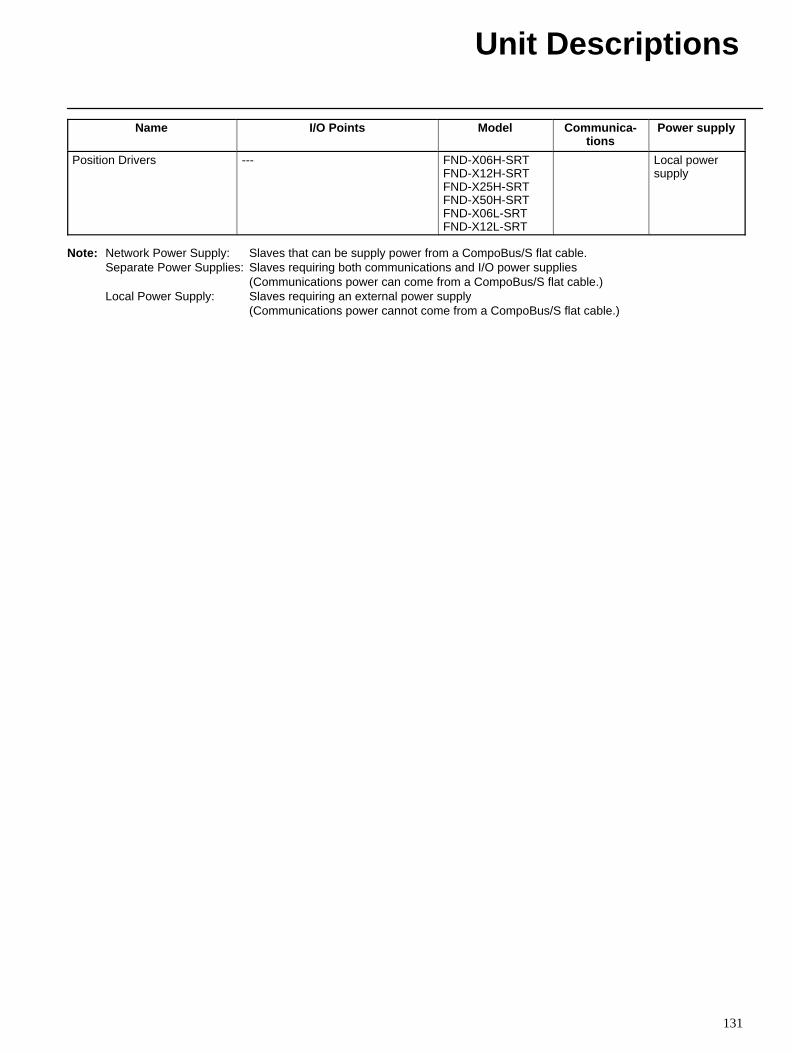
Unit Descriptions
131
Name Power supplyCommunica-tions
ModelI/O Points
Position Drivers --- FND-X06H-SRTFND-X12H-SRTFND-X25H-SRTFND-X50H-SRTFND-X06L-SRTFND-X12L-SRT
Local powersupply
Note: Network Power Supply: Slaves that can be supply power from a CompoBus/S flat cable.Separate Power Supplies: Slaves requiring both communications and I/O power supplies
(Communications power can come from a CompoBus/S flat cable.)Local Power Supply: Slaves requiring an external power supply
(Communications power cannot come from a CompoBus/S flat cable.)
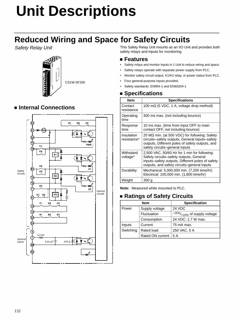
Unit Descriptions
132
Reduced Wiring and Space for Safety CircuitsSafety Relay Unit
CS1W-SF200
Internal Connections
3.3 kΩ
0.01 µF 470 Ω
Internalcircuits
Safetycircuits
Generalinputs
This Safety Relay Unit mounts as an I/O Unit and provides bothsafety relays and inputs for monitoring.
Features• Safety relays and monitor inputs in 1 Unit to reduce wiring and space.
• Safety relays operate with separate power supply from PLC.
• Monitor safety circuit output, K1/K2 relay, or power status from PLC.
• Four general-purpose inputs provided.
• Safety standards: EN954-1 and EN60204-1
SpecificationsItem Specifications
Contactresistance
100 mΩ (5 VDC, 1 A, voltage drop method)
Operatingtime
300 ms max. (not including bounce)
Responsetime
10 ms max. (time from input OFF to maincontact OFF, not including bounce)
Insulationresistance*
20 MΩ min. (at 500 VDC) for following: Safetycircuits–safety outputs, General inputs–safetyoutputs, Different poles of safety outputs, andsafety circuits–general inputs
Withstandvoltage*
2,500 VAC, 50/60 Hz for 1 min for following:Safety circuits–safety outputs, Generalinputs–safety outputs, Different poles of safetyoutputs, and safety circuits–general inputs
Durability Mechanical: 5,000,000 min. (7,200 time/hr)Electrical: 100,000 min. (1,800 time/hr)
Weight 300 g
Note: Measured while mounted to PLC.
Ratings of Safety CircuitsItem Specification
Power Supply voltage 24 VDC
Fluctuation –15%/+10% of supply voltage
Consumption 24 VDC: 1.7 W max.
Inputs Current 75 mA max.
Switching Rated load 250 VAC, 5 Ag
Rated ON current 5 A
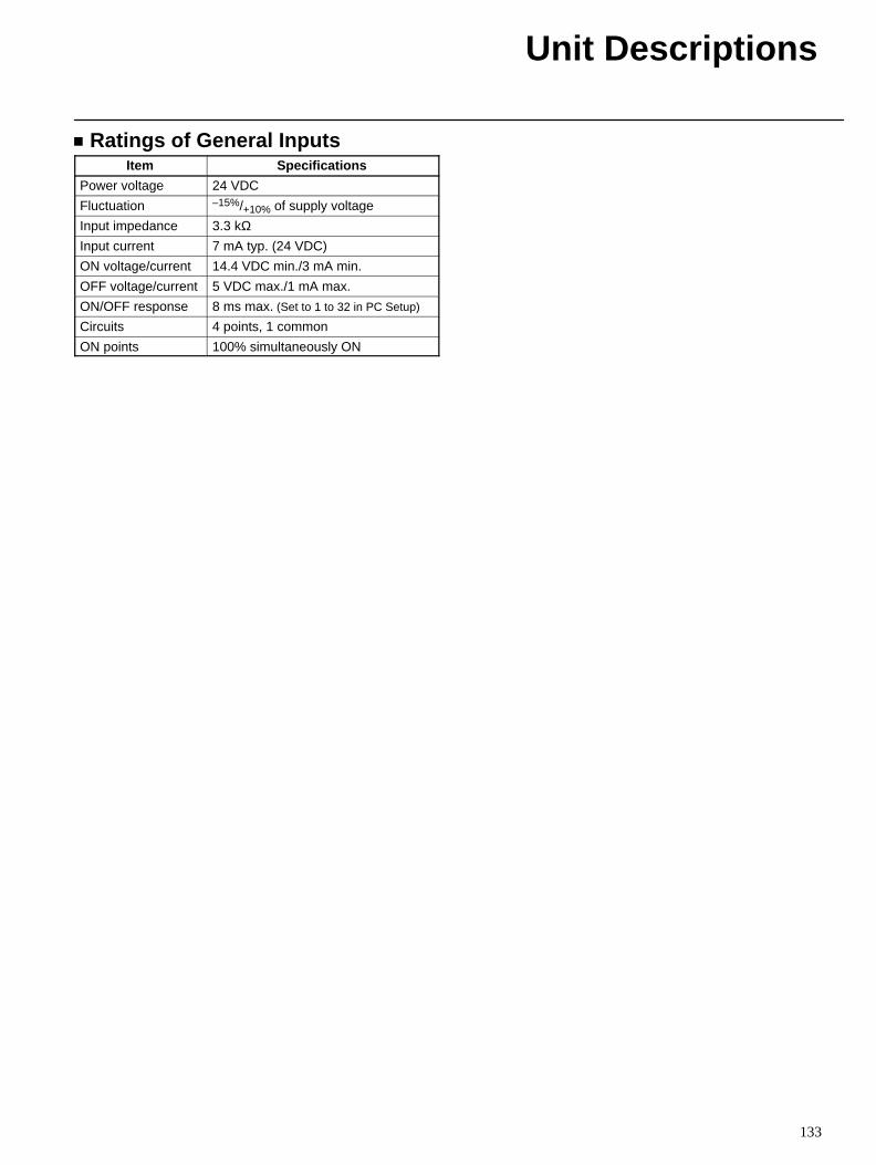
Unit Descriptions
133
Ratings of General InputsItem Specifications
Power voltage 24 VDC
Fluctuation –15%/+10% of supply voltage
Input impedance 3.3 kΩInput current 7 mA typ. (24 VDC)
ON voltage/current 14.4 VDC min./3 mA min.
OFF voltage/current 5 VDC max./1 mA max.
ON/OFF response 8 ms max. (Set to 1 to 32 in PC Setup)
Circuits 4 points, 1 common
ON points 100% simultaneously ON
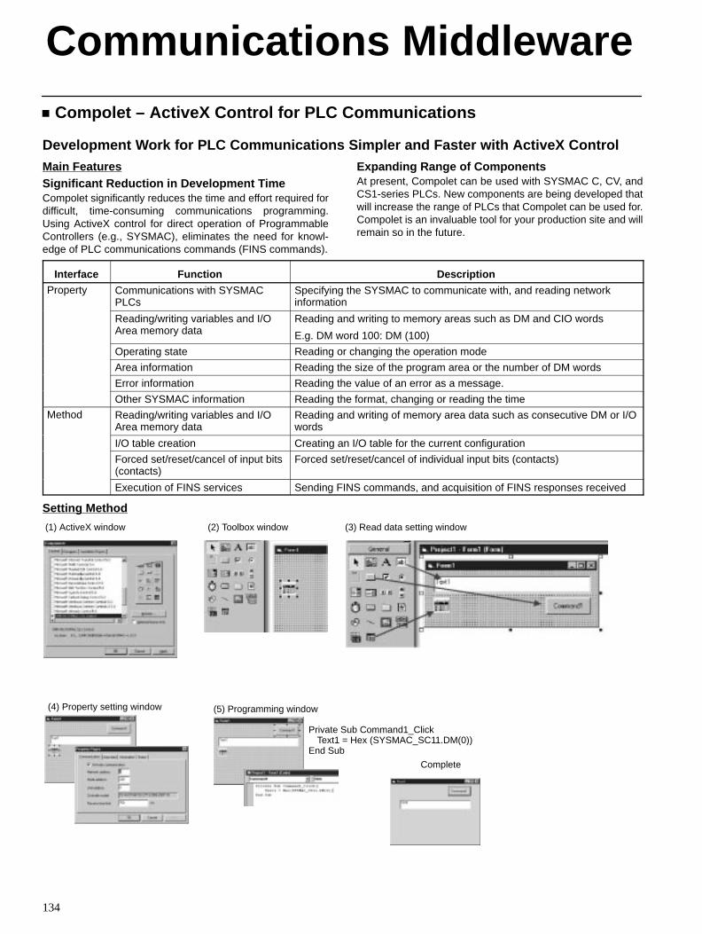
134
Compolet – ActiveX Control for PLC Communications
Development Work for PLC Communications Simpler and Faster with ActiveX ControlMain FeaturesSignificant Reduction in Development TimeCompolet significantly reduces the time and effort required fordifficult, time-consuming communications programming.Using ActiveX control for direct operation of ProgrammableControllers (e.g., SYSMAC), eliminates the need for knowl-edge of PLC communications commands (FINS commands).
Expanding Range of ComponentsAt present, Compolet can be used with SYSMAC C, CV, andCS1-series PLCs. New components are being developed thatwill increase the range of PLCs that Compolet can be used for.Compolet is an invaluable tool for your production site and willremain so in the future.
Interface Function DescriptionProperty Communications with SYSMAC
PLCsSpecifying the SYSMAC to communicate with, and reading networkinformation
Reading/writing variables and I/OArea memory data
Reading and writing to memory areas such as DM and CIO words
E.g. DM word 100: DM (100)
Operating state Reading or changing the operation mode
Area information Reading the size of the program area or the number of DM words
Error information Reading the value of an error as a message.
Other SYSMAC information Reading the format, changing or reading the time
Method Reading/writing variables and I/OArea memory data
Reading and writing of memory area data such as consecutive DM or I/Owords
I/O table creation Creating an I/O table for the current configuration
Forced set/reset/cancel of input bits(contacts)
Forced set/reset/cancel of individual input bits (contacts)
Execution of FINS services Sending FINS commands, and acquisition of FINS responses received
Setting Method
Complete
Private Sub Command1_ClickText1 = Hex (SYSMAC_SC11.DM(0))
End Sub
(1) ActiveX window (2) Toolbox window (3) Read data setting window
(4) Property setting window (5) Programming window
Communications Middleware
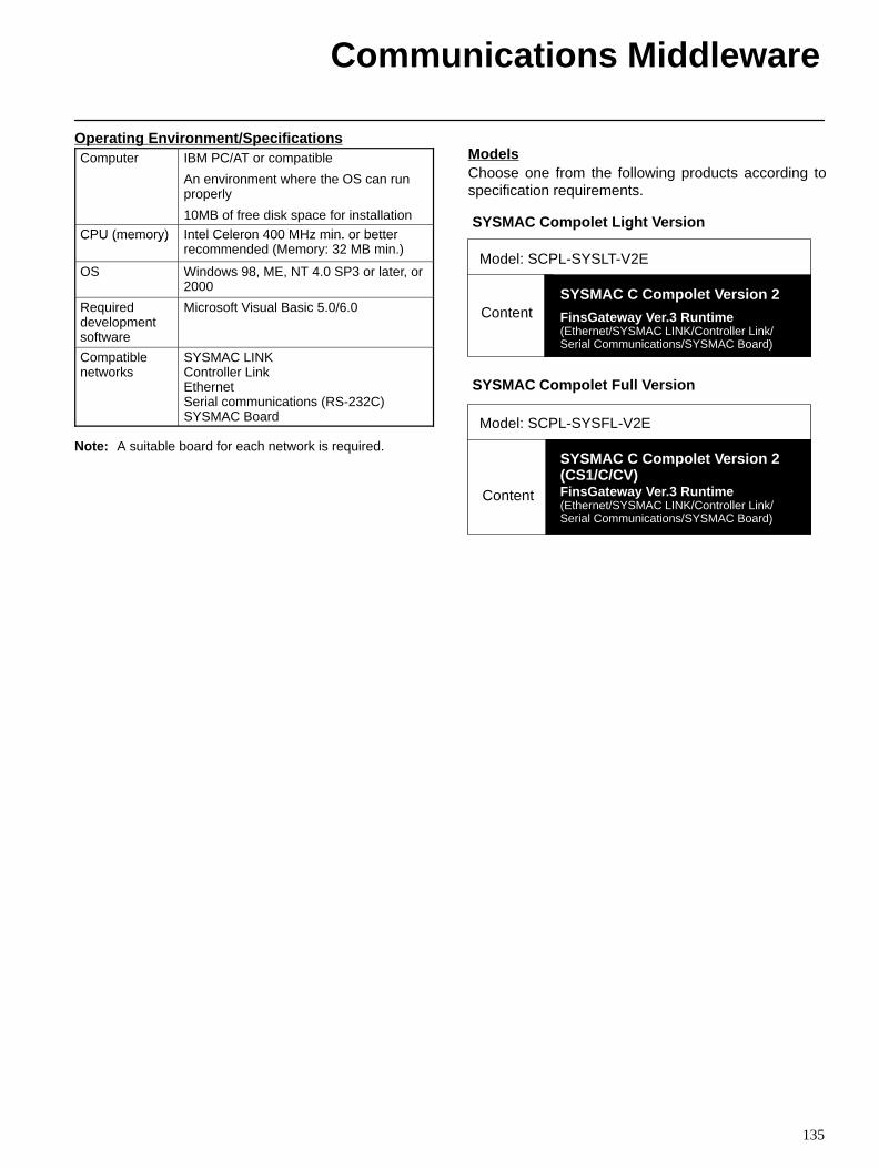
Communications Middleware
135
Operating Environment/SpecificationsComputer IBM PC/AT or compatible
An environment where the OS can runproperly
10MB of free disk space for installation
CPU (memory) Intel Celeron 400 MHz min. or betterCPU (memory) Intel Celeron 400 MHz min. or betterrecommended (Memory: 32 MB min.)
OS Windows 98, ME, NT 4.0 SP3 or later, or2000
Requireddevelopmentsoftware
Microsoft Visual Basic 5.0/6.0
Compatiblenetworks
SYSMAC LINKController LinkEthernetSerial communications (RS-232C)SYSMAC Board
Note: A suitable board for each network is required.
ModelsChoose one from the following products according tospecification requirements.
SYSMAC Compolet Light Version
Model: SCPL-SYSLT-V2E
ContentSYSMAC C Compolet Version 2
FinsGateway Ver.3 Runtime(Ethernet/SYSMAC LINK/Controller Link/Serial Communications/SYSMAC Board)
SYSMAC Compolet Full Version
Model: SCPL-SYSFL-V2E
Content
SYSMAC C Compolet Version 2(CS1/C/CV)FinsGateway Ver.3 Runtime(Ethernet/SYSMAC LINK/Controller Link/ Serial Communications/SYSMAC Board)
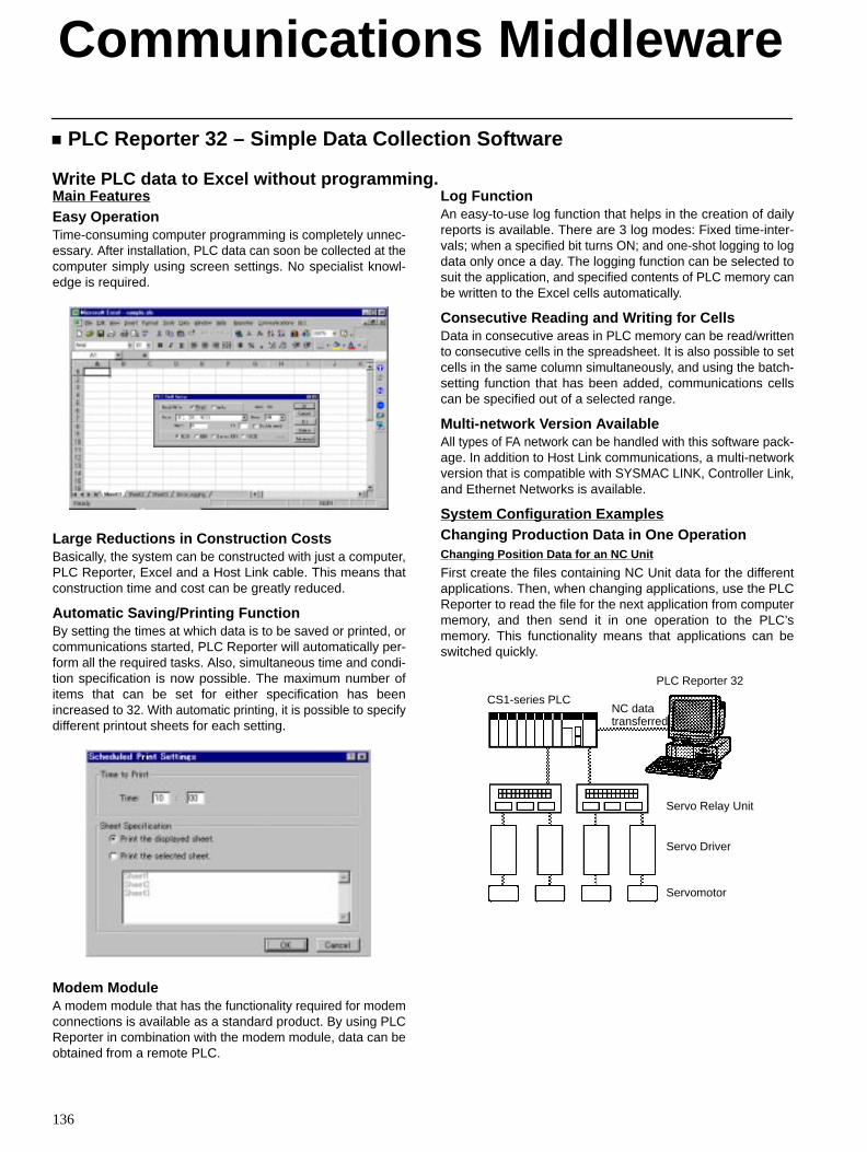
Communications Middleware
136
PLC Reporter 32 – Simple Data Collection Software
Write PLC data to Excel without programming.Main FeaturesEasy OperationTime-consuming computer programming is completely unnec-essary. After installation, PLC data can soon be collected at thecomputer simply using screen settings. No specialist knowl-edge is required.
Large Reductions in Construction CostsBasically, the system can be constructed with just a computer,PLC Reporter, Excel and a Host Link cable. This means thatconstruction time and cost can be greatly reduced.
Automatic Saving/Printing FunctionBy setting the times at which data is to be saved or printed, orcommunications started, PLC Reporter will automatically per-form all the required tasks. Also, simultaneous time and condi-tion specification is now possible. The maximum number ofitems that can be set for either specification has beenincreased to 32. With automatic printing, it is possible to specifydifferent printout sheets for each setting.
Modem ModuleA modem module that has the functionality required for modemconnections is available as a standard product. By using PLCReporter in combination with the modem module, data can beobtained from a remote PLC.
Log FunctionAn easy-to-use log function that helps in the creation of dailyreports is available. There are 3 log modes: Fixed time-inter-vals; when a specified bit turns ON; and one-shot logging to logdata only once a day. The logging function can be selected tosuit the application, and specified contents of PLC memory canbe written to the Excel cells automatically.
Consecutive Reading and Writing for CellsData in consecutive areas in PLC memory can be read/writtento consecutive cells in the spreadsheet. It is also possible to setcells in the same column simultaneously, and using the batch-setting function that has been added, communications cellscan be specified out of a selected range.
Multi-network Version AvailableAll types of FA network can be handled with this software pack-age. In addition to Host Link communications, a multi-networkversion that is compatible with SYSMAC LINK, Controller Link,and Ethernet Networks is available.
System Configuration ExamplesChanging Production Data in One OperationChanging Position Data for an NC Unit
First create the files containing NC Unit data for the differentapplications. Then, when changing applications, use the PLCReporter to read the file for the next application from computermemory, and then send it in one operation to the PLC’smemory. This functionality means that applications can beswitched quickly.
CS1-series PLC
PLC Reporter 32
NC datatransferred
Servo Relay Unit
Servomotor
Servo Driver
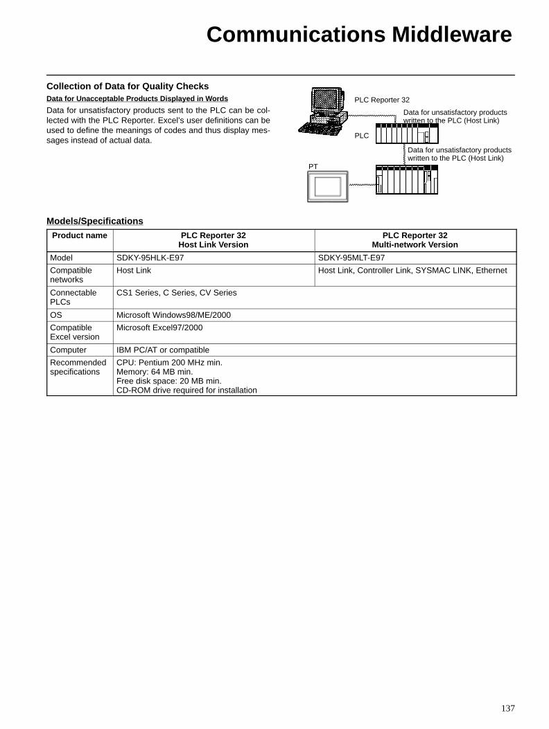
Communications Middleware
137
Collection of Data for Quality ChecksData for Unacceptable Products Displayed in W ords
Data for unsatisfactory products sent to the PLC can be col-lected with the PLC Reporter. Excel’s user definitions can beused to define the meanings of codes and thus display mes-sages instead of actual data.
PLC Reporter 32
Data for unsatisfactory productswritten to the PLC (Host Link)
PLC
Data for unsatisfactory productswritten to the PLC (Host Link)
PT
Models/Specifications
Product name PLC Reporter 32Host Link Version
PLC Reporter 32Multi-network Version
Model SDKY-95HLK-E97 SDKY-95MLT-E97
Compatiblenetworks
Host Link Host Link, Controller Link, SYSMAC LINK, Ethernet
ConnectablePLCs
CS1 Series, C Series, CV Series
OS Microsoft Windows98/ME/2000
CompatibleExcel version
Microsoft Excel97/2000
Computer IBM PC/AT or compatible
Recommendedspecifications
CPU: Pentium 200 MHz min.Memory: 64 MB min.Free disk space: 20 MB min.CD-ROM drive required for installation

138
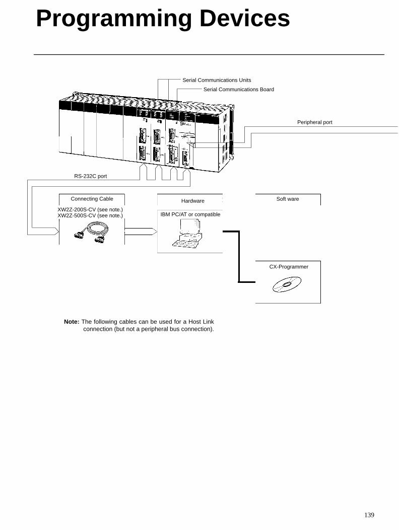
139
Serial Communications Units
Serial Communications Board
Peripheral port
CX-Programmer
HardwareConnecting Cable
RS-232C port
XW2Z-200S-CV (see note.)XW2Z-500S-CV (see note.)
Soft ware
IBM PC/AT or compatible
Note: The following cables can be used for a Host Linkconnection (but not a peripheral bus connection).
Programming Devices
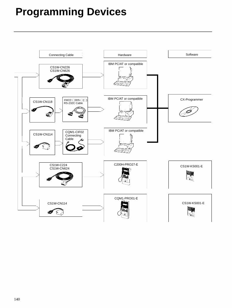
Programming Devices
140
Hardware Software
CX-Programmer
Connecting Cable
CS1W-CN226CS1W-CN626
CS1W-C224CS1W-CN624
CS1W-CN114
CS1W-KS001-E
CS1W-KS001-E
IBM PC/AT or compatible
C200H-PRO27-E
CQM1-PRO01-E
CS1W-CN118
CQM1-CIF02ConnectingCable
IBM PC/AT or compatible
IBM PC/AT or compatible
XW2Z-00S-()RS-232C Cable
CS1W-CN114
141
ORDERING GUIDECPU Rack 142. . . . . . . . . . . . . . . . . . . . . . . . . . . . . . . . . . . . . . . . . . . . . . . . . . . . . .
Expansion Racks 144. . . . . . . . . . . . . . . . . . . . . . . . . . . . . . . . . . . . . . . . . . . . . . . .
C200H Basic I/O Units 145. . . . . . . . . . . . . . . . . . . . . . . . . . . . . . . . . . . . . . . . . . . .
C200H Group-2 High-density I/O Units 146. . . . . . . . . . . . . . . . . . . . . . . . . . . . .
CS1 High-density Input Units 148. . . . . . . . . . . . . . . . . . . . . . . . . . . . . . . . . . . . . .
C200H High-density I/O Units Classified as Special I/O Units 149. . . . . . . . . . .
C200H Special I/O Units 150. . . . . . . . . . . . . . . . . . . . . . . . . . . . . . . . . . . . . . . . . .
CS1 Special I/O Units 157. . . . . . . . . . . . . . . . . . . . . . . . . . . . . . . . . . . . . . . . . . . . .
CS1 CPU Bus Units 159. . . . . . . . . . . . . . . . . . . . . . . . . . . . . . . . . . . . . . . . . . . . . .
DeviceNet Slaves 161. . . . . . . . . . . . . . . . . . . . . . . . . . . . . . . . . . . . . . . . . . . . . . . . .
MULTIPLE I/O TERMINAL Units 163. . . . . . . . . . . . . . . . . . . . . . . . . . . . . . . . .
CompoBus/S Slave Units 163. . . . . . . . . . . . . . . . . . . . . . . . . . . . . . . . . . . . . . . . . .
Optional Products 166. . . . . . . . . . . . . . . . . . . . . . . . . . . . . . . . . . . . . . . . . . . . . . . .
EMC DirectivesOMRON devices that comply with EC Directives also conform tothe related EMC standards so that they can be more easily builtinto other devices or the overall machine. The actual productshave been checked for conformity to EMC standards (see thefollowing note). Whether the products conform to the standardsin the system used by the customer, however, must be con-firmed by the customer.
EMC-related performance of the OMRON devices that complywith EC Directives will vary depending on the configuration, wir-ing, and other conditions of the equipment or control panel onwhich the OMRON devices are installed. The customer must,therefore, perform the final check to confirm that devices and theoverall machine conform to EMC standards.
Applicable EMC Standards
EMS (Electromagnetic Susceptibility):EN61131-2
EMI (Electromagnetic Interference):EN50081-2 (Radiated emission: 10-m regulations)
Low Voltage DirectiveOMRON Power Supply Units and I/O Units have been deter-mined safe when operating at voltages of 50 to 1,000 VAC and75 to 1,500 VDC according to the safety standards inEN61131-2.
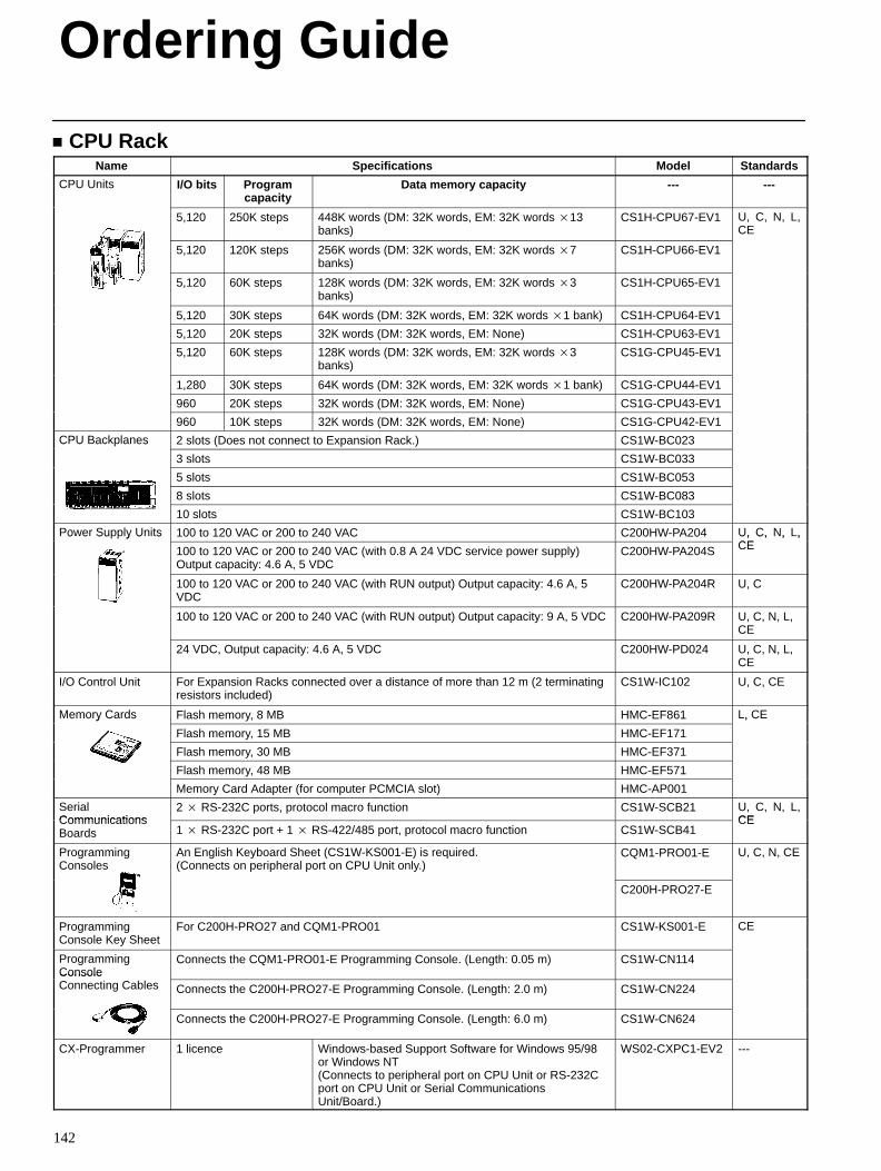
Ordering Guide
142
CPU RackName Specifications Model Standards
CPU Units I/O bits Programcapacity
Data memory capacity --- ---
5,120 250K steps 448K words (DM: 32K words, EM: 32K words 13banks)
CS1H-CPU67-EV1 U, C, N, L,CE
5,120 120K steps 256K words (DM: 32K words, EM: 32K words 7banks)
CS1H-CPU66-EV1
5,120 60K steps 128K words (DM: 32K words, EM: 32K words 3banks)
CS1H-CPU65-EV1
5,120 30K steps 64K words (DM: 32K words, EM: 32K words 1 bank) CS1H-CPU64-EV1
5,120 20K steps 32K words (DM: 32K words, EM: None) CS1H-CPU63-EV1
5,120 60K steps 128K words (DM: 32K words, EM: 32K words 3banks)
CS1G-CPU45-EV1
1,280 30K steps 64K words (DM: 32K words, EM: 32K words 1 bank) CS1G-CPU44-EV1
960 20K steps 32K words (DM: 32K words, EM: None) CS1G-CPU43-EV1
960 10K steps 32K words (DM: 32K words, EM: None) CS1G-CPU42-EV1
CPU Backplanes 2 slots (Does not connect to Expansion Rack.) CS1W-BC023C U ac a es
3 slots CS1W-BC033
5 slots CS1W-BC053
8 slots CS1W-BC083
10 slots CS1W-BC103
Power Supply Units 100 to 120 VAC or 200 to 240 VAC C200HW-PA204 U, C, N, L,CE
o e Su y U s
100 to 120 VAC or 200 to 240 VAC (with 0.8 A 24 VDC service power supply)Output capacity: 4.6 A, 5 VDC
C200HW-PA204S
U, C, , ,CE
100 to 120 VAC or 200 to 240 VAC (with RUN output) Output capacity: 4.6 A, 5VDC
C200HW-PA204R U, C
100 to 120 VAC or 200 to 240 VAC (with RUN output) Output capacity: 9 A, 5 VDC C200HW-PA209R U, C, N, L,CE
24 VDC, Output capacity: 4.6 A, 5 VDC C200HW-PD024 U, C, N, L,CE
I/O Control Unit For Expansion Racks connected over a distance of more than 12 m (2 terminatingresistors included)
CS1W-IC102 U, C, CE
Memory Cards Flash memory, 8 MB HMC-EF861 L, CEe o y Ca ds
Flash memory, 15 MB HMC-EF171
, C
Flash memory, 30 MB HMC-EF371
Flash memory, 48 MB HMC-EF571
Memory Card Adapter (for computer PCMCIA slot) HMC-AP001
SerialCommunications
2 RS-232C ports, protocol macro function CS1W-SCB21 U, C, N, L,CECommunications
Boards 1 RS-232C port + 1 RS-422/485 port, protocol macro function CS1W-SCB41CE
ProgrammingConsoles
An English Keyboard Sheet (CS1W-KS001-E) is required.(Connects on peripheral port on CPU Unit only.)
CQM1-PRO01-E U, C, N, CE
C200H-PRO27-E
ProgrammingConsole Key Sheet
For C200H-PRO27 and CQM1-PRO01 CS1W-KS001-E CE
ProgrammingConsole
Connects the CQM1-PRO01-E Programming Console. (Length: 0.05 m) CS1W-CN114ConsoleConnecting Cables Connects the C200H-PRO27-E Programming Console. (Length: 2.0 m) CS1W-CN224
Connects the C200H-PRO27-E Programming Console. (Length: 6.0 m) CS1W-CN624
CX-Programmer 1 licence Windows-based Support Software for Windows 95/98or Windows NT(Connects to peripheral port on CPU Unit or RS-232Cport on CPU Unit or Serial CommunicationsUnit/Board.)
WS02-CXPC1-EV2 ---
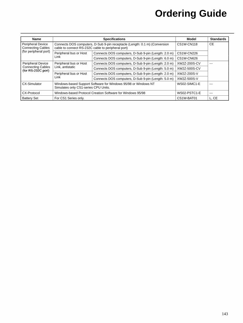
Ordering Guide
143
Name StandardsModelSpecifications
Peripheral DeviceConnecting Cables(f i h l t)
Connects DOS computers, D-Sub 9-pin receptacle (Length: 0.1 m) (Conversioncable to connect RS-232C cable to peripheral port)
CS1W-CN118 CEg
(for peripheral port) Peripheral bus or HostLi k
Connects DOS computers, D-Sub 9-pin (Length: 2.0 m) CS1W-CN226e e a bus o osLink Connects DOS computers, D-Sub 9-pin (Length: 6.0 m) CS1W-CN626
Peripheral DeviceC ti C bl
Peripheral bus or HostLi k ti t ti
Connects DOS computers, D-Sub 9-pin (Length: 2.0 m) XW2Z-200S-CV ---e e a e ceConnecting Cables(for RS-232C port)
e e a bus o osLink, antistatic Connects DOS computers, D-Sub 9-pin (Length: 5.0 m) XW2Z-500S-CV
(for RS-232C port)Peripheral bus or HostLi k
Connects DOS computers, D-Sub 9-pin (Length: 2.0 m) XW2Z-200S-Ve e a bus o osLink Connects DOS computers, D-Sub 9-pin (Length: 5.0 m) XW2Z-500S-V
CX-Simulator Windows-based Support Software for Windows 95/98 or Windows NTSimulates only CS1-series CPU Units.
WS02-SIMC1-E ---
CX-Protocol Windows-based Protocol Creation Software for Windows 95/98 WS02-PSTC1-E ---
Battery Set For CS1 Series only. CS1W-BAT01 L, CE
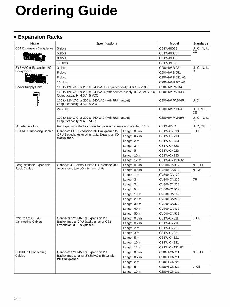
Ordering Guide
144
Expansion RacksName Specifications Model Standards
CS1 Expansion Backplanes 3 slots CS1W-BI033 U, C, N, L,CE
CS a s o ac a es
5 slots CS1W-BI053
U, C, , ,CE
8 slots CS1W-BI083
10 slots CS1W-BI103
SYSMAC α Expansion I/OB k l
3 slots C200HW-BI031 U, C, N, L,CE
S S C α a s o /OBackplanes 5 slots C200HW-BI051
U, C, , ,CE
8 slots C200HW-BI081-V1
10 slots C200HW-BI101-V1
Power Supply Units 100 to 120 VAC or 200 to 240 VAC, Output capacity: 4.6 A, 5 VDC C200HW-PA204o e Su y U s
100 to 120 VAC or 200 to 240 VAC (with service supply: 0.8 A, 24 VDC),Output capacity: 4.6 A, 5 VDC
C200HW-PA204S
100 to 120 VAC or 200 to 240 VAC (with RUN output)Output capacity: 4.6 A, 5 VDC
C200HW-PA204R U, C
24 VDC, C200HW-PD024 U, C, N, L,CE
100 to 120 VAC or 200 to 240 VAC (with RUN output)Output capacity: 9 A, 5 VDC
C200HW-PA209R U, C, N, L,CE
I/O Interface Unit For Expansion Racks connected over a distance of more than 12 m CS1W-II102 U, C, CE
CS1 I/O Connecting Cables Connects CS1 Expansion I/O Backplanes toCPU B k l th CS1 E i I/O
Length: 0.3 m CS1W-CN313 L, CECS /O Co ec g Cab es Co ec s CS a s o /O ac a es oCPU Backplanes or other CS1 Expansion I/OBackplanes
Length: 0.7 m CS1W-CN713
, C
Backplanes.Length: 2 m CS1W-CN223
Length: 3 m CS1W-CN323
Length: 5 m CS1W-CN523
Length: 10 m CS1W-CN133
Length: 12 m CS1W-CN133-B2
Long-distance ExpansionR k C bl
Connect I/O Control Unit to I/O Interface Unitt t I/O I t f U it
Length: 0.3 m CV500-CN312 N, L, CEo g d s a ce a s oRack Cables
Co ec /O Co o U o /O e ace Uor connects two I/O Interface Units Length: 0.6 m CV500-CN612 N, CE
Length: 1 m CV500-CN122
, C
Length: 2 m CV500-CN222 CE
Length: 3 m CV500-CN322
C
Length: 5 m CV500-CN522
Length: 10 m CV500-CN132
Length: 20 m CV500-CN232
Length: 30 m CV500-CN332
Length: 40 m CV500-CN432
Length: 50 m CV500-CN532
CS1 to C200H I/OC ti C bl
Connects SYSMAC α Expansion I/OB k l t CPU B k l CS1
Length: 0.3 m CS1W-CN311 L, CECS o C 00 /OConnecting Cables
Co ec s S S C α a s o /OBackplanes to CPU Backplanes or CS1Expansion I/O Backplanes
Length: 0.7 m CS1W-CN711
, C
Expansion I/O Backplanes.Length: 2 m CS1W-CN221
Length: 3 m CS1W-CN321
Length: 5 m CS1W-CN521
Length: 10 m CS1W-CN131
Length: 12 m CS1W-CN131-B2
C200H I/O ConnectingC bl
Connects SYSMAC α Expansion I/OB k l t th SYSMAC E i
Length: 0.3 m C200H-CN311 N, L, CEC 00 /O Co ec gCables
Co ec s S S C α a s o /OBackplanes to other SYSMAC α ExpansionI/O Backplanes
Length: 0.7 m C200H-CN711
, , C
I/O Backplanes.Length: 2 m C200H-CN221
Length: 5 m C200H-CN521 L, CE
Length: 10 m C200H-CN131
, C
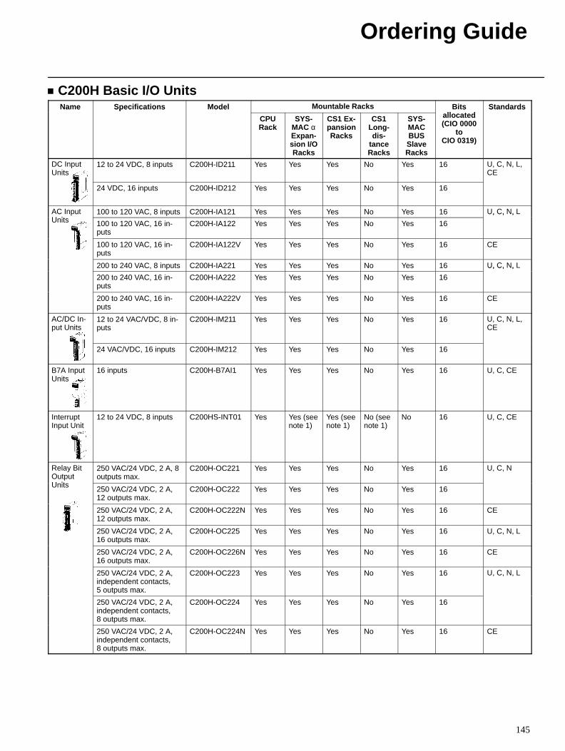
Ordering Guide
145
C200H Basic I/O UnitsName Specifications Model Mountable Racks Bits
ll t dStandardsa e Spec ca o s ode
CPURack
SYS-MAC αExpan-sion I/ORacks
CS1 Ex-pansionRacks
CS1Long-dis-
tanceRacks
SYS-MACBUSSlaveRacks
sallocated(CIO 0000
toCIO 0319)
S a da ds
DC InputUnits
12 to 24 VDC, 8 inputs C200H-ID211 Yes Yes Yes No Yes 16 U, C, N, L,CE
24 VDC, 16 inputs C200H-ID212 Yes Yes Yes No Yes 16
AC InputU it
100 to 120 VAC, 8 inputs C200H-IA121 Yes Yes Yes No Yes 16 U, C, N, LC uUnits 100 to 120 VAC, 16 in-
putsC200H-IA122 Yes Yes Yes No Yes 16
U, C, ,
100 to 120 VAC, 16 in-puts
C200H-IA122V Yes Yes Yes No Yes 16 CE
200 to 240 VAC, 8 inputs C200H-IA221 Yes Yes Yes No Yes 16 U, C, N, L
200 to 240 VAC, 16 in-puts
C200H-IA222 Yes Yes Yes No Yes 16
U, C, ,
200 to 240 VAC, 16 in-puts
C200H-IA222V Yes Yes Yes No Yes 16 CE
AC/DC In-put Units
12 to 24 VAC/VDC, 8 in-puts
C200H-IM211 Yes Yes Yes No Yes 16 U, C, N, L,CE
24 VAC/VDC, 16 inputs C200H-IM212 Yes Yes Yes No Yes 16
B7A InputUnits
16 inputs C200H-B7AI1 Yes Yes Yes No Yes 16 U, C, CE
InterruptInput Unit
12 to 24 VDC, 8 inputs C200HS-INT01 Yes Yes (seenote 1)
Yes (seenote 1)
No (seenote 1)
No 16 U, C, CE
Relay BitOutputU it
250 VAC/24 VDC, 2 A, 8outputs max.
C200H-OC221 Yes Yes Yes No Yes 16 U, C, N
Units 250 VAC/24 VDC, 2 A,12 outputs max.
C200H-OC222 Yes Yes Yes No Yes 16
250 VAC/24 VDC, 2 A,12 outputs max.
C200H-OC222N Yes Yes Yes No Yes 16 CE
250 VAC/24 VDC, 2 A,16 outputs max.
C200H-OC225 Yes Yes Yes No Yes 16 U, C, N, L
250 VAC/24 VDC, 2 A,16 outputs max.
C200H-OC226N Yes Yes Yes No Yes 16 CE
250 VAC/24 VDC, 2 A,independent contacts,5 outputs max.
C200H-OC223 Yes Yes Yes No Yes 16 U, C, N, L
250 VAC/24 VDC, 2 A,independent contacts,8 outputs max.
C200H-OC224 Yes Yes Yes No Yes 16
250 VAC/24 VDC, 2 A,independent contacts,8 outputs max.
C200H-OC224N Yes Yes Yes No Yes 16 CE
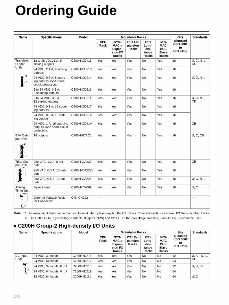
Ordering Guide
146
Name StandardsBitsallocated(CIO 0000
toCIO 0319)
Mountable RacksModelSpecificationsName StandardsBitsallocated(CIO 0000
toCIO 0319)
SYS-MACBUSSlaveRacks
CS1Long-dis-
tanceRacks
CS1 Ex-pansionRacks
SYS-MAC αExpan-sion I/ORacks
CPURack
ModelSpecifications
TransistorOutputU it
12 to 48 VDC, 1 A, 8sinking outputs
C200H-OD411 Yes Yes Yes No Yes 16 U, C, N, L,CE
Units 24 VDC, 2.1 A, 8 sinkingoutputs
C200H-OD213 Yes Yes Yes No Yes 16
24 VDC, 0.8 A, 8 sourc-ing outputs, load short-circuit protection.
C200H-OD214 Yes Yes Yes No Yes 16 U, C, N, L
5 to 24 VDC, 0.3 A,8 sourcing outputs
C200H-OD216 Yes Yes Yes No Yes 16
5 to 24 VDC, 0.3 A,12 sinking outputs
C200H-OD211 Yes Yes Yes No Yes 16 U, C, N, L,CE
24 VDC, 0.3 A, 12 sourc-ing outputs
C200H-OD217 Yes Yes Yes No Yes 16
24 VDC, 0.3 A, 16 sink-ing outputs
C200H-OD212 Yes Yes Yes No Yes 16
24 VDC, 1 A, 16 sourcingoutputs, load short-circuitprotection.
C200H-OD21A Yes Yes Yes No Yes 16 CE
B7A Out-put Units
16 outputs C200H-B7AO1 Yes Yes Yes No Yes 16 U, C, CE
Triac Out-put Units
250 VAC, 1.2 A, 8 out-puts
C200H-OA223 Yes Yes Yes No Yes 16 CE
250 VAC, 0.3 A, 12 out-puts
C200H-OA222V Yes Yes Yes No Yes 16
250 VAC, 0.5 A, 12 out-puts
C200H-OA224 Yes Yes Yes No Yes 16 U, C, N, L
AnalogTimer Unit
4-point timer C200H-TM001 Yes Yes Yes No Yes 16 U, C
External Variable Resis-tor Connector:
C4K-CN223 --- ---
Note: 1. Interrupt Input Units cannot be used to input interrupts on any but the CPU Rack. They will function as normal I/O Units on other Racks.
2. The C200H-ID001 (no-voltage contacts, 8 inputs, NPN) and C200H-ID002 (no-voltage contacts, 8 inputs, PNP) cannot be used.
C200H Group-2 High-density I/O UnitsName Specifications Model Mountable Racks Bits
ll t dStandardsa e Spec ca o s ode
CPURack
SYS-MAC αExpan-sion I/ORacks
CS1 Ex-pansionRacks
CS1Long-dis-
tanceRacks
SYS-MACBUSSlaveRacks
sallocated(CIO 0000
toCIO 0319)
S a da ds
DC InputU it
24 VDC, 32 inputs C200H-ID216 Yes Yes Yes No No 32 U, C, N, L,CEUnits
24 VDC, 64 inputs C200H-ID217 Yes Yes Yes No No 64
, , , ,CE
24 VDC, 32 inputs, 6 mA C200H-ID218 Yes Yes Yes No No 32 U, C, CE
24 VDC, 64 inputs, 6 mA C200H-ID219 Yes Yes Yes No No 64
, ,
12 VDC, 64 inputs C200H-ID111 Yes Yes Yes No No 64 U, C
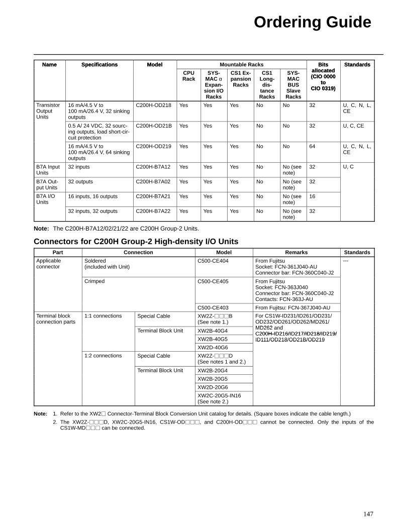
Ordering Guide
147
Name StandardsBitsallocated(CIO 0000
toCIO 0319)
Mountable RacksModelSpecificationsName StandardsBitsallocated(CIO 0000
toCIO 0319)
SYS-MACBUSSlaveRacks
CS1Long-dis-
tanceRacks
CS1 Ex-pansionRacks
SYS-MAC αExpan-sion I/ORacks
CPURack
ModelSpecifications
TransistorOutputUnits
16 mA/4.5 V to100 mA/26.4 V, 32 sinkingoutputs
C200H-OD218 Yes Yes Yes No No 32 U, C, N, L,CE
0.5 A/ 24 VDC, 32 sourc-ing outputs, load short-cir-cuit protection
C200H-OD21B Yes Yes Yes No No 32 U, C, CE
16 mA/4.5 V to100 mA/26.4 V, 64 sinkingoutputs
C200H-OD219 Yes Yes Yes No No 64 U, C, N, L,CE
B7A InputUnits
32 inputs C200H-B7A12 Yes Yes Yes No No (seenote)
32 U, C
B7A Out-put Units
32 outputs C200H-B7A02 Yes Yes Yes No No (seenote)
32
B7A I/OUnits
16 inputs, 16 outputs C200H-B7A21 Yes Yes Yes No No (seenote)
16
32 inputs, 32 outputs C200H-B7A22 Yes Yes Yes No No (seenote)
32
Note: The C200H-B7A12/02/21/22 are C200H Group-2 Units.
Connectors for C200H Group-2 High-density I/O UnitsPart Connection Model Remarks Standards
Applicableconnector
Soldered(included with Unit)
C500-CE404 From FujitsuSocket: FCN-361J040-AUConnector bar: FCN-360C040-J2
---
Crimped C500-CE405 From FujitsuSocket: FCN-363J040Connector bar: FCN-360C040-J2Contacts: FCN-363J-AU
C500-CE403 From Fujitsu: FCN-367J040-AU
Terminal blockconnection parts
1:1 connections Special Cable XW2Z-B(See note 1.)
For CS1W-ID231/ID261/OD231/OD232/OD261/OD262/MD261/MD262 dTerminal Block Unit XW2B-40G4 MD262 andC200H-ID216/ID217/ID218/ID219/
e a oc U
XW2B-40G5C200H-ID216/ID217/ID218/ID219/ID111/OD218/OD21B/OD219
XW2D-40G6
ID111/OD218/OD21B/OD219
1:2 connections Special Cable XW2Z-D(See notes 1 and 2.)
Terminal Block Unit XW2B-20G4e a oc U
XW2B-20G5
XW2D-20G6
XW2C-20G5-IN16(See note 2.)
Note: 1. Refer to the XW2 Connector-Terminal Block Conversion Unit catalog for details. (Square boxes indicate the cable length.)
2. The XW2Z-D, XW2C-20G5-IN16, CS1W-OD, and C200H-OD cannot be connected. Only the inputs of theCS1W-MD can be connected.
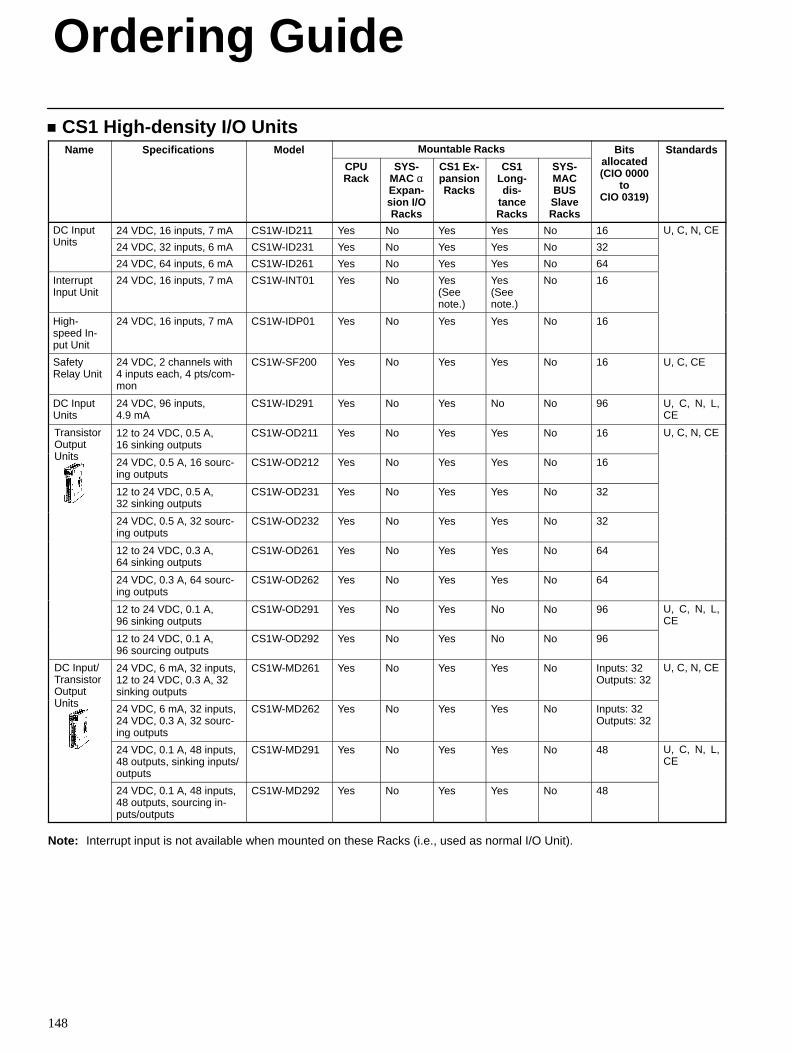
Ordering Guide
148
CS1 High-density I/O UnitsName Specifications Model Mountable Racks Bits
ll t dStandardsa e Spec ca o s ode
CPURack
SYS-MAC αExpan-sion I/ORacks
CS1 Ex-pansionRacks
CS1Long-dis-
tanceRacks
SYS-MACBUSSlaveRacks
sallocated(CIO 0000
toCIO 0319)
S a da ds
DC InputU it
24 VDC, 16 inputs, 7 mA CS1W-ID211 Yes No Yes Yes No 16 U, C, N, CEC uUnits 24 VDC, 32 inputs, 6 mA CS1W-ID231 Yes No Yes Yes No 32
U, C, , C
24 VDC, 64 inputs, 6 mA CS1W-ID261 Yes No Yes Yes No 64
InterruptInput Unit
24 VDC, 16 inputs, 7 mA CS1W-INT01 Yes No Yes(Seenote.)
Yes(Seenote.)
No 16
High-speed In-put Unit
24 VDC, 16 inputs, 7 mA CS1W-IDP01 Yes No Yes Yes No 16
SafetyRelay Unit
24 VDC, 2 channels with4 inputs each, 4 pts/com-mon
CS1W-SF200 Yes No Yes Yes No 16 U, C, CE
DC InputUnits
24 VDC, 96 inputs,4.9 mA
CS1W-ID291 Yes No Yes No No 96 U, C, N, L,CE
TransistorOutputU it
12 to 24 VDC, 0.5 A,16 sinking outputs
CS1W-OD211 Yes No Yes Yes No 16 U, C, N, CE
Units 24 VDC, 0.5 A, 16 sourc-ing outputs
CS1W-OD212 Yes No Yes Yes No 16
12 to 24 VDC, 0.5 A,32 sinking outputs
CS1W-OD231 Yes No Yes Yes No 32
24 VDC, 0.5 A, 32 sourc-ing outputs
CS1W-OD232 Yes No Yes Yes No 32
12 to 24 VDC, 0.3 A,64 sinking outputs
CS1W-OD261 Yes No Yes Yes No 64
24 VDC, 0.3 A, 64 sourc-ing outputs
CS1W-OD262 Yes No Yes Yes No 64
12 to 24 VDC, 0.1 A,96 sinking outputs
CS1W-OD291 Yes No Yes No No 96 U, C, N, L,CE
12 to 24 VDC, 0.1 A,96 sourcing outputs
CS1W-OD292 Yes No Yes No No 96
DC Input/TransistorOutputU it
24 VDC, 6 mA, 32 inputs,12 to 24 VDC, 0.3 A, 32sinking outputs
CS1W-MD261 Yes No Yes Yes No Inputs: 32Outputs: 32
U, C, N, CE
Units 24 VDC, 6 mA, 32 inputs,24 VDC, 0.3 A, 32 sourc-ing outputs
CS1W-MD262 Yes No Yes Yes No Inputs: 32Outputs: 32
24 VDC, 0.1 A, 48 inputs,48 outputs, sinking inputs/outputs
CS1W-MD291 Yes No Yes Yes No 48 U, C, N, L,CE
24 VDC, 0.1 A, 48 inputs,48 outputs, sourcing in-puts/outputs
CS1W-MD292 Yes No Yes Yes No 48
Note: Interrupt input is not available when mounted on these Racks (i.e., used as normal I/O Unit).
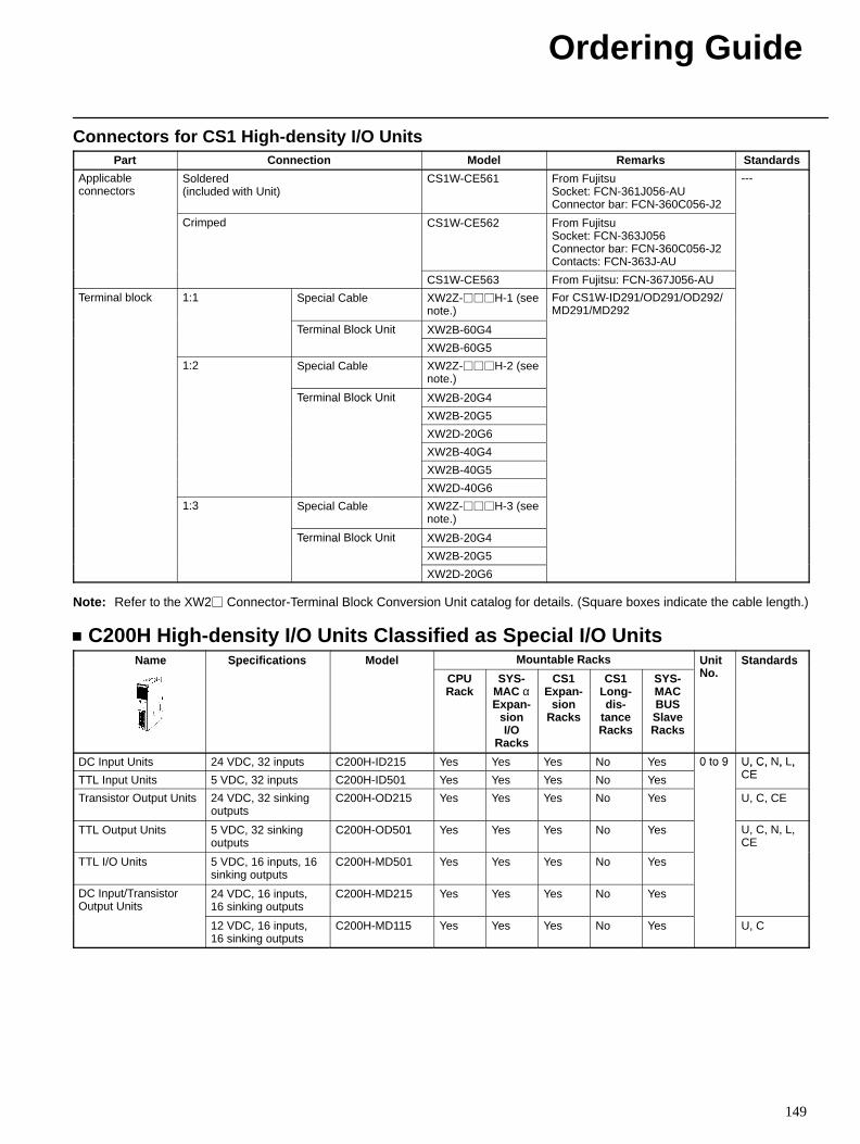
Ordering Guide
149
Connectors for CS1 High-density I/O UnitsPart Connection Model Remarks Standards
Applicableconnectors
Soldered(included with Unit)
CS1W-CE561 From FujitsuSocket: FCN-361J056-AUConnector bar: FCN-360C056-J2
---
Crimped CS1W-CE562 From FujitsuSocket: FCN-363J056Connector bar: FCN-360C056-J2Contacts: FCN-363J-AU
CS1W-CE563 From Fujitsu: FCN-367J056-AU
Terminal block 1:1 Special Cable XW2Z-H-1 (seenote.)
For CS1W-ID291/OD291/OD292/MD291/MD292
Terminal Block Unit XW2B-60G4e a oc U
XW2B-60G5
1:2 Special Cable XW2Z-H-2 (seenote.)
Terminal Block Unit XW2B-20G4e a oc U
XW2B-20G5
XW2D-20G6
XW2B-40G4
XW2B-40G5
XW2D-40G6
1:3 Special Cable XW2Z-H-3 (seenote.)
Terminal Block Unit XW2B-20G4e a oc U
XW2B-20G5
XW2D-20G6
Note: Refer to the XW2 Connector-Terminal Block Conversion Unit catalog for details. (Square boxes indicate the cable length.)
C200H High-density I/O Units Classified as Special I/O UnitsName Specifications Model Mountable Racks Unit
NStandardsa e Spec ca o s ode
CPURack
SYS-MAC αExpan-
sionI/O
Racks
CS1Expan-
sionRacks
CS1Long-dis-
tanceRacks
SYS-MACBUSSlaveRacks
UNo.
S a da ds
DC Input Units 24 VDC, 32 inputs C200H-ID215 Yes Yes Yes No Yes 0 to 9 U, C, N, L,CETTL Input Units 5 VDC, 32 inputs C200H-ID501 Yes Yes Yes No Yes
0 o 9 U, C, , ,CE
Transistor Output Units 24 VDC, 32 sinkingoutputs
C200H-OD215 Yes Yes Yes No Yes U, C, CE
TTL Output Units 5 VDC, 32 sinkingoutputs
C200H-OD501 Yes Yes Yes No Yes U, C, N, L,CE
TTL I/O Units 5 VDC, 16 inputs, 16sinking outputs
C200H-MD501 Yes Yes Yes No Yes
DC Input/TransistorOutput Units
24 VDC, 16 inputs,16 sinking outputs
C200H-MD215 Yes Yes Yes No Yes
12 VDC, 16 inputs,16 sinking outputs
C200H-MD115 Yes Yes Yes No Yes U, C
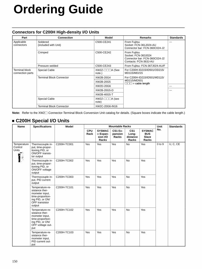
Ordering Guide
150
Connectors for C200H High-density I/O UnitsPart Connection Model Remarks Standards
Applicableconnectors
Soldered(included with Unit)
C500-CE241 From FujitsuSocket: FCN-361J024-AUConnector bar: FCN-360C024-J2
---
Crimped C500-CE242 From FujitsuSocket: FCN-363J024Connector bar: FCN-360C024-J2Contacts: FCN-363J-AU
Pressure welded C500-CE243 From Fujitsu: FCN-367J024-AU/F
Terminal blockconnection parts
Special Cable XW2Z-A (Seenote.)
For C200H-ID215/ID501/OD215/MD115/MD215
Terminal Block Connector XW2B-20G4 For C200H-ID215/ID501/MD115/MD215/MD501
e a oc Co ec o
XW2B-20G5
o C 00 5/ 50 / 5/MD215/MD501 = cable length
XW2D-20G6 = cable length
---
XW2B-20G5-D ---
XW2B-40G5-T
Special Cable XW2Z-A (seenote)
Terminal Block Connector XW2C-20G6-IN16
Note: Refer to the XW2 Connector-Terminal Block Conversion Unit catalog for details. (Square boxes indicate the cable length.)
C200H Special I/O UnitsName Specifications Model Mountable Racks Unit
NStandardsa e Spec ca o s ode
CPURack
SYSMACα Expan -sion I/ORacks
CS1 Ex-pansionRacks
CS1Long-
distanceRacks
SYSMACBUSSlaveRacks
UNo.
S a da ds
TemperatureControlUnits
Thermocouple in-put, time-propor-tioning PID, orON/OFF transis-tor output
C200H-TC001 Yes Yes Yes No Yes 0 to 9 U, C, CE
Thermocouple in-put, time-propor-tioning PID, orON/OFF voltageoutput
C200H-TC002 Yes Yes Yes No Yes
Thermocouple in-put, PID currentoutput
C200H-TC003 Yes Yes Yes No Yes
Temperature-re-sistance ther-mometer input,time-proportion-ing PID, or ON/OFF transistoroutput
C200H-TC101 Yes Yes Yes No Yes
Temperature-re-sistance ther-mometer input,time-proportion-ing PID, or ON/OFF voltage out-put
C200H-TC102 Yes Yes Yes No Yes
Temperature-re-sistance ther-mometer input,PID current out-put
C200H-TC103 Yes Yes Yes No Yes
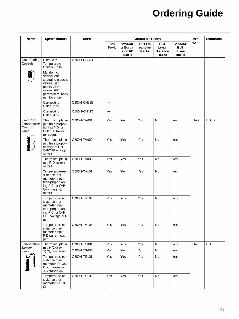
Ordering Guide
151
Name StandardsUnitNo.
Mountable RacksModelSpecificationsName StandardsUnitNo.SYSMAC
BUSSlaveRacks
CS1Long-
distanceRacks
CS1 Ex-pansionRacks
SYSMACα Expan -sion I/ORacks
CPURack
ModelSpecifications
Data SettingConsole
Used withTemperatureControl Units.
Monitoring,setting, andchanging presentvalues, setpoints, alarmvalues, PIDparameters, banknumbers, etc.
C200H-DSC01 --- --- ---
ConnectingCable, 2 m
C200H-CN225 ---
ConnectingCable, 4 m
C200H-CN425 ---
Heat/CoolTemperatureControlUnits
Thermocouple in-put, time-propor-tioning PID, orON/OFF transis-tor output
C200H-TV001 Yes Yes Yes No Yes 0 to 9 U, C, CE
Thermocouple in-put, time-propor-tioning PID, orON/OFF voltageoutput
C200H-TV002 Yes Yes Yes No Yes
Thermocouple in-put, PID currentoutput
C200H-TV003 Yes Yes Yes No Yes
Temperature-re-sistance ther-mometer input,time-proportion-ing PID, or ON/OFF transistoroutput
C200H-TV101 Yes Yes Yes No Yes
Temperature-re-sistance ther-mometer input,time-proportion-ing PID, or ON/OFF voltage out-put
C200H-TV102 Yes Yes Yes No Yes
Temperature-re-sistance ther-mometer input,PID current out-put
C200H-TV103 Yes Yes Yes No Yes
TemperatureSensor
Thermocouple in-put K(CA) or
C200H-TS001 Yes Yes Yes No Yes 0 to 9 U, CSensorUnits
put, K(CA) orJ(IC), selectable C200H-TS002 Yes Yes Yes No Yes
Temperature-re-sistance ther-mometer, Pt 100Ω, conforms toJIS standards
C200H-TS101 Yes Yes Yes No Yes
Temperature-re-sistance ther-mometer, Pt 100Ω
C200H-TS102 Yes Yes Yes No Yes
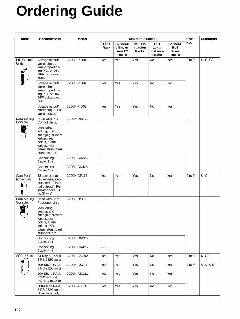
Ordering Guide
152
Name StandardsUnitNo.
Mountable RacksModelSpecificationsName StandardsUnitNo.SYSMAC
BUSSlaveRacks
CS1Long-
distanceRacks
CS1 Ex-pansionRacks
SYSMACα Expan -sion I/ORacks
CPURack
ModelSpecifications
PID ControlUnits
Voltage output/current input,time-proportion-ing PID, or ON/OFF transistoroutput
C200H-PID01 Yes Yes Yes No Yes 0 to 9 U, C, CE
Voltage output/current input,time-proportion-ing PID, or ON/OFF voltage out-put
C200H-PID02 Yes Yes Yes No Yes
Voltage output/current input, PIDcurrent output
C200H-PID03 Yes Yes Yes No Yes
Data SettingConsole
Used with PIDControl Units.
Monitoring,setting, andchanging presentvalues, setpoints, alarmvalues, PIDparameters, banknumbers, etc.
C200H-DSC01 --- --- ---
ConnectingCable, 2 m
C200H-CN225 ---
ConnectingCable, 4 m
C200H-CN425 ---
Cam Posi-tioner Unit
48 cam outputs(16 external out-puts and 32 inter-nal outputs), Re-solver speed: 20µs (5 kHz)
C200H-CP114 Yes Yes Yes No Yes 0 to 9 U, C
Data SettingConsole
Used with CamPositioner Unit.
Monitoring,setting, andchanging presentvalues, setpoints, alarmvalues, PIDparameters, banknumbers, etc.
C200H-DSC01 --- --- ---
ConnectingCable, 2 m
C200H-CN225 ---
ConnectingCable, 4 m
C200H-CN425 ---
ASCII Units 24-Kbyte RAM,k2 RS-232C ports
C200H-ASC02 Yes Yes Yes No Yes 0 to 9 N, CE
200-Kbyte RAM,2 RS-232C ports
C200H-ASC11 Yes Yes Yes No Yes 0 to F U, C, CE
200-Kbyte RAM,RS-232C port,RS-422/485 port
C200H-ASC21 Yes Yes Yes No Yes
200-Kbyte RAM,3 RS-232C ports(1 terminal only)
C200H-ASC31 Yes Yes Yes No Yes
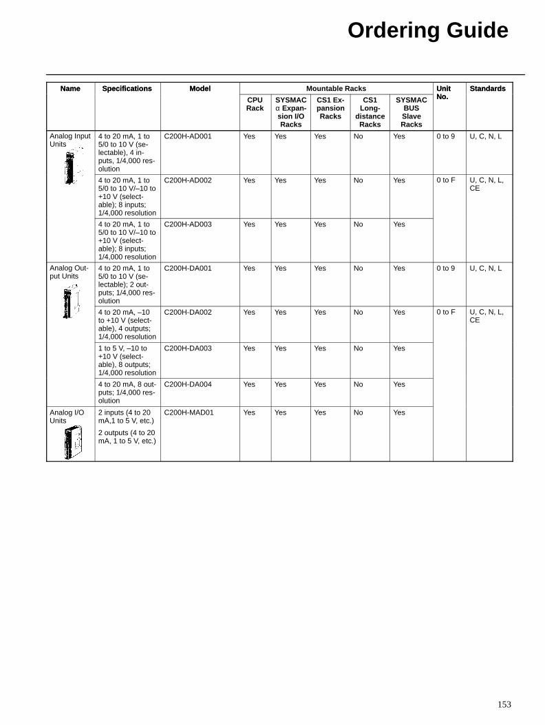
Ordering Guide
153
Name StandardsUnitNo.
Mountable RacksModelSpecificationsName StandardsUnitNo.SYSMAC
BUSSlaveRacks
CS1Long-
distanceRacks
CS1 Ex-pansionRacks
SYSMACα Expan -sion I/ORacks
CPURack
ModelSpecifications
Analog InputUnits
4 to 20 mA, 1 to5/0 to 10 V (se-lectable), 4 in-puts, 1/4,000 res-olution
C200H-AD001 Yes Yes Yes No Yes 0 to 9 U, C, N, L
4 to 20 mA, 1 to5/0 to 10 V/–10 to+10 V (select-able); 8 inputs;1/4,000 resolution
C200H-AD002 Yes Yes Yes No Yes 0 to F U, C, N, L,CE
4 to 20 mA, 1 to5/0 to 10 V/–10 to+10 V (select-able); 8 inputs;1/4,000 resolution
C200H-AD003 Yes Yes Yes No Yes
Analog Out-put Units
4 to 20 mA, 1 to5/0 to 10 V (se-lectable); 2 out-puts; 1/4,000 res-olution
C200H-DA001 Yes Yes Yes No Yes 0 to 9 U, C, N, L
4 to 20 mA, –10to +10 V (select-able), 4 outputs;1/4,000 resolution
C200H-DA002 Yes Yes Yes No Yes 0 to F U, C, N, L,CE
1 to 5 V, –10 to+10 V (select-able), 8 outputs;1/4,000 resolution
C200H-DA003 Yes Yes Yes No Yes
4 to 20 mA, 8 out-puts; 1/4,000 res-olution
C200H-DA004 Yes Yes Yes No Yes
Analog I/OUnits
2 inputs (4 to 20mA,1 to 5 V, etc.)
2 outputs (4 to 20mA, 1 to 5 V, etc.)
C200H-MAD01 Yes Yes Yes No Yes
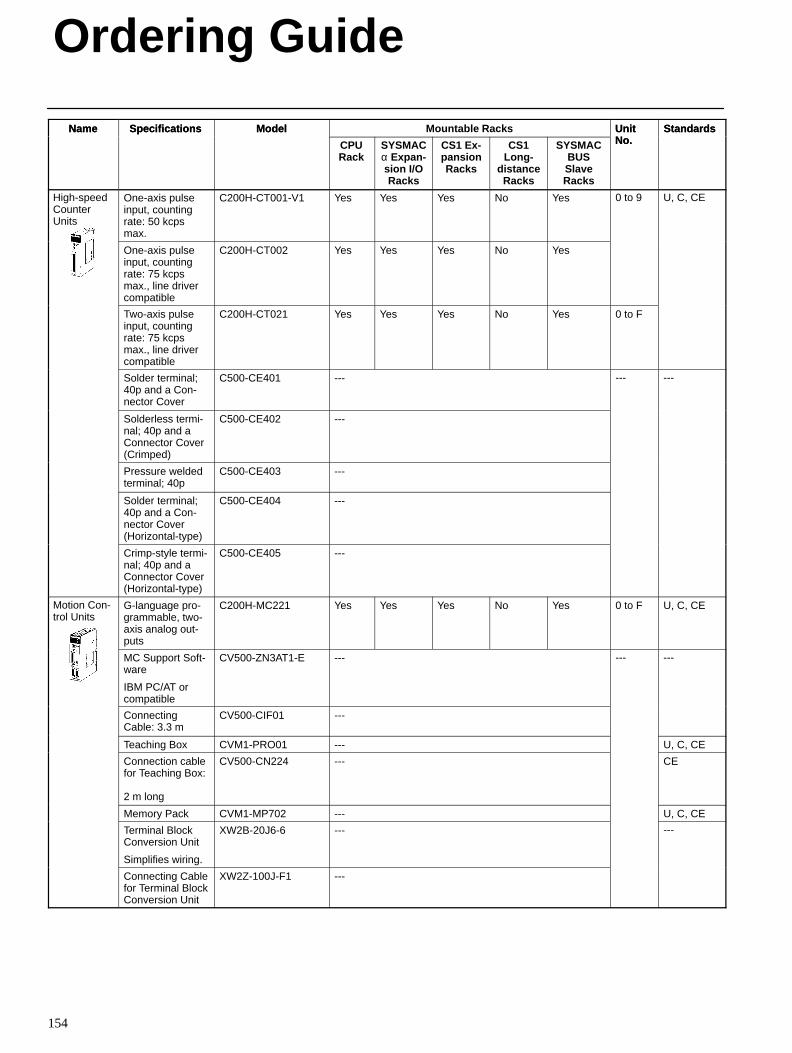
Ordering Guide
154
Name StandardsUnitNo.
Mountable RacksModelSpecificationsName StandardsUnitNo.SYSMAC
BUSSlaveRacks
CS1Long-
distanceRacks
CS1 Ex-pansionRacks
SYSMACα Expan -sion I/ORacks
CPURack
ModelSpecifications
High-speedCounterUnits
One-axis pulseinput, countingrate: 50 kcpsmax.
C200H-CT001-V1 Yes Yes Yes No Yes 0 to 9 U, C, CE
One-axis pulseinput, countingrate: 75 kcpsmax., line drivercompatible
C200H-CT002 Yes Yes Yes No Yes
Two-axis pulseinput, countingrate: 75 kcpsmax., line drivercompatible
C200H-CT021 Yes Yes Yes No Yes 0 to F
Solder terminal;40p and a Con-nector Cover
C500-CE401 --- --- ---
Solderless termi-nal; 40p and aConnector Cover(Crimped)
C500-CE402 ---
Pressure weldedterminal; 40p
C500-CE403 ---
Solder terminal;40p and a Con-nector Cover(Horizontal-type)
C500-CE404 ---
Crimp-style termi-nal; 40p and aConnector Cover(Horizontal-type)
C500-CE405 ---
Motion Con-trol Units
G-language pro-grammable, two-axis analog out-puts
C200H-MC221 Yes Yes Yes No Yes 0 to F U, C, CE
MC Support Soft-ware
IBM PC/AT orcompatible
CV500-ZN3AT1-E --- --- ---
ConnectingCable: 3.3 m
CV500-CIF01 ---
Teaching Box CVM1-PRO01 --- U, C, CE
Connection cablefor Teaching Box:
2 m long
CV500-CN224 --- CE
Memory Pack CVM1-MP702 --- U, C, CE
Terminal BlockConversion Unit
Simplifies wiring.
XW2B-20J6-6 --- ---
Connecting Cablefor Terminal BlockConversion Unit
XW2Z-100J-F1 ---
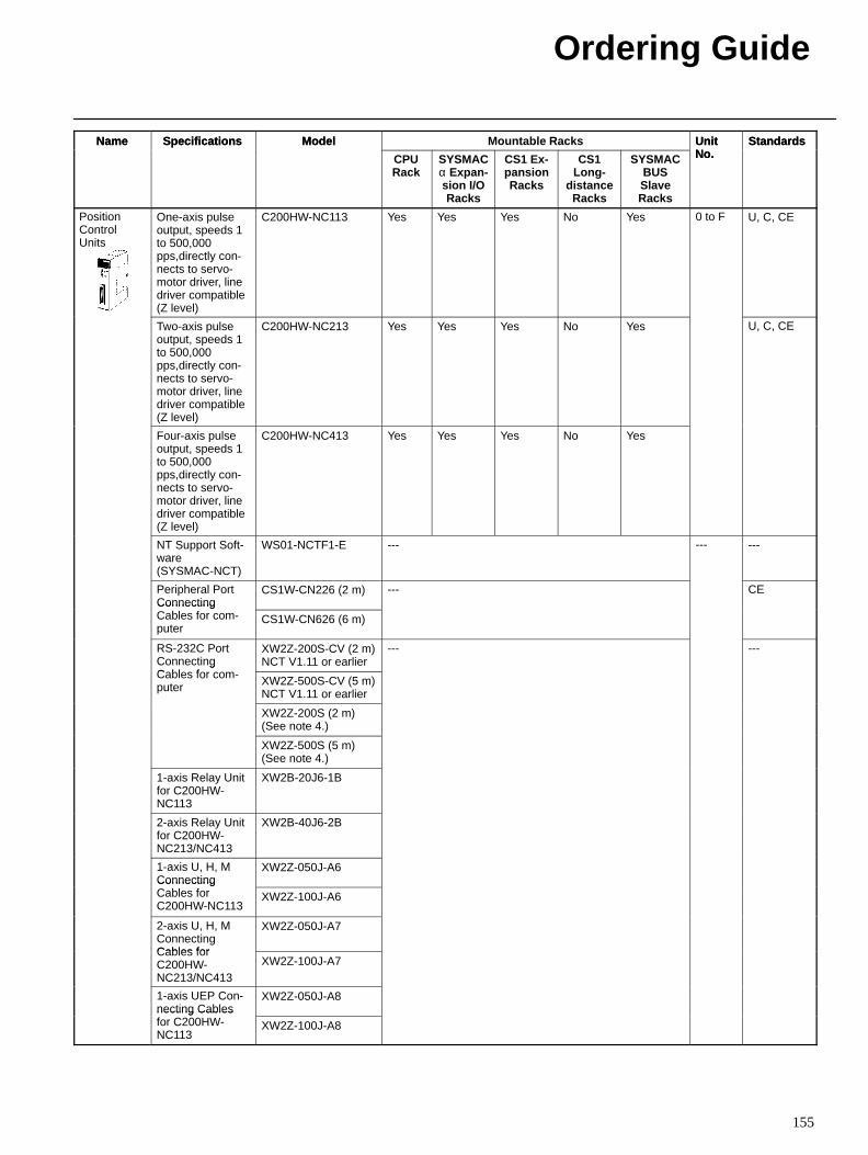
Ordering Guide
155
Name StandardsUnitNo.
Mountable RacksModelSpecificationsName StandardsUnitNo.SYSMAC
BUSSlaveRacks
CS1Long-
distanceRacks
CS1 Ex-pansionRacks
SYSMACα Expan -sion I/ORacks
CPURack
ModelSpecifications
PositionControlUnits
One-axis pulseoutput, speeds 1to 500,000pps,directly con-nects to servo-motor driver, linedriver compatible(Z level)
C200HW-NC113 Yes Yes Yes No Yes 0 to F U, C, CE
Two-axis pulseoutput, speeds 1to 500,000pps,directly con-nects to servo-motor driver, linedriver compatible(Z level)
C200HW-NC213 Yes Yes Yes No Yes U, C, CE
Four-axis pulseoutput, speeds 1to 500,000pps,directly con-nects to servo-motor driver, linedriver compatible(Z level)
C200HW-NC413 Yes Yes Yes No Yes
NT Support Soft-ware (SYSMAC-NCT)
WS01-NCTF1-E --- --- ---
Peripheral PortConnecting
CS1W-CN226 (2 m) --- CEConnectingCables for com-puter
CS1W-CN626 (6 m)
RS-232C PortConnectingC bl f
XW2Z-200S-CV (2 m)NCT V1.11 or earlier
--- ---g
Cables for com-puter XW2Z-500S-CV (5 m)
NCT V1.11 or earlier
XW2Z-200S (2 m)(See note 4.)
XW2Z-500S (5 m)(See note 4.)
1-axis Relay Unitfor C200HW-NC113
XW2B-20J6-1B
2-axis Relay Unitfor C200HW-NC213/NC413
XW2B-40J6-2B
1-axis U, H, MConnecting
XW2Z-050J-A6ConnectingCables forC200HW-NC113
XW2Z-100J-A6
2-axis U, H, MConnectingCables for
XW2Z-050J-A7
Cables forC200HW-NC213/NC413
XW2Z-100J-A7
1-axis UEP Con-necting Cables
XW2Z-050J-A8necting Cablesfor C200HW-NC113
XW2Z-100J-A8
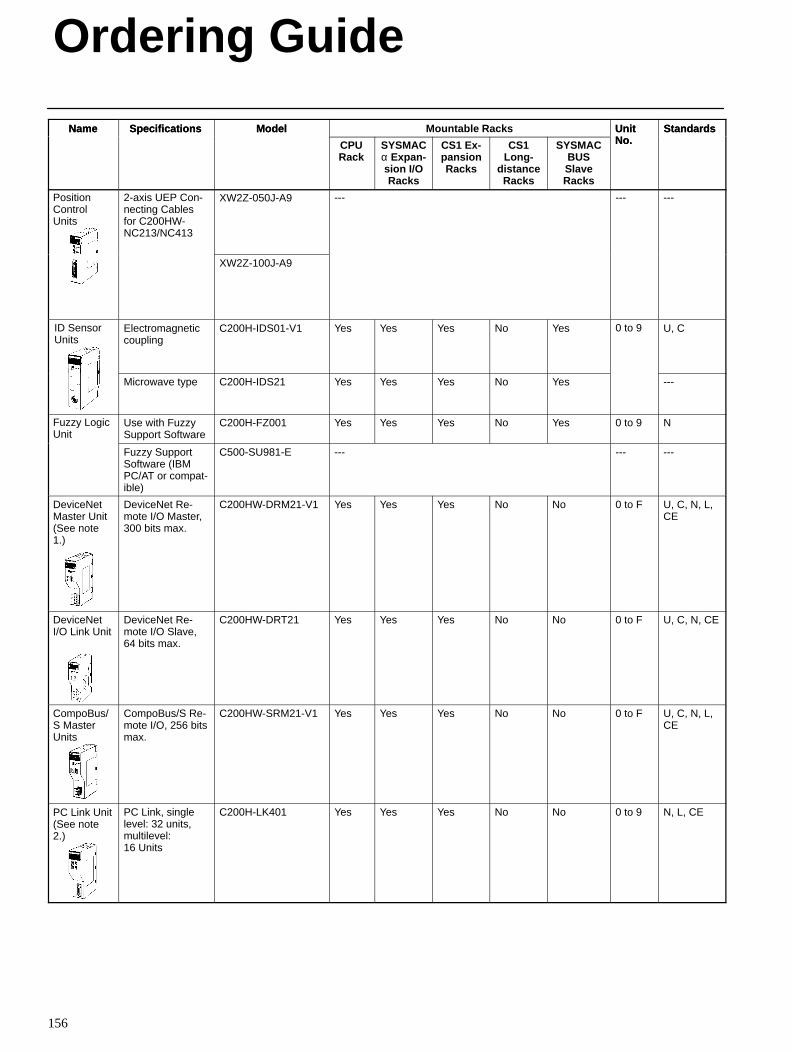
Ordering Guide
156
Name StandardsUnitNo.
Mountable RacksModelSpecificationsName StandardsUnitNo.SYSMAC
BUSSlaveRacks
CS1Long-
distanceRacks
CS1 Ex-pansionRacks
SYSMACα Expan -sion I/ORacks
CPURack
ModelSpecifications
PositionControlUnits
2-axis UEP Con-necting Cablesfor C200HW-NC213/NC413
XW2Z-050J-A9 --- --- ---
XW2Z-100J-A9
ID SensorUnits
Electromagneticcoupling
C200H-IDS01-V1 Yes Yes Yes No Yes 0 to 9 U, C
Microwave type C200H-IDS21 Yes Yes Yes No Yes ---
Fuzzy LogicUnit
Use with FuzzySupport Software
C200H-FZ001 Yes Yes Yes No Yes 0 to 9 N
Fuzzy SupportSoftware (IBMPC/AT or compat-ible)
C500-SU981-E --- --- ---
DeviceNetMaster Unit(See note1.)
DeviceNet Re-mote I/O Master,300 bits max.
C200HW-DRM21-V1 Yes Yes Yes No No 0 to F U, C, N, L,CE
DeviceNetI/O Link Unit
DeviceNet Re-mote I/O Slave,64 bits max.
C200HW-DRT21 Yes Yes Yes No No 0 to F U, C, N, CE
CompoBus/S MasterUnits
CompoBus/S Re-mote I/O, 256 bitsmax.
C200HW-SRM21-V1 Yes Yes Yes No No 0 to F U, C, N, L,CE
PC Link Unit(See note2.)
PC Link, singlelevel: 32 units,multilevel:16 Units
C200H-LK401 Yes Yes Yes No No 0 to 9 N, L, CE
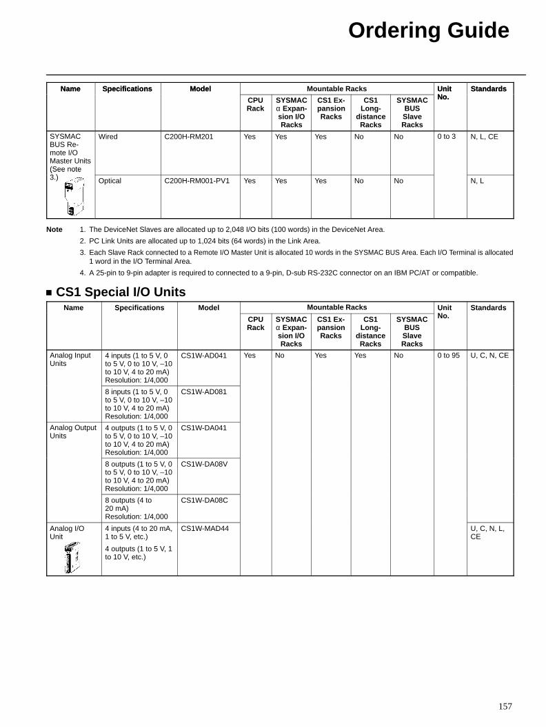
Ordering Guide
157
Name StandardsUnitNo.
Mountable RacksModelSpecificationsName StandardsUnitNo.SYSMAC
BUSSlaveRacks
CS1Long-
distanceRacks
CS1 Ex-pansionRacks
SYSMACα Expan -sion I/ORacks
CPURack
ModelSpecifications
SYSMACBUS Re-mote I/OMaster Units(See note3 )
Wired C200H-RM201 Yes Yes Yes No No 0 to 3 N, L, CE
(See ote3.) Optical C200H-RM001-PV1 Yes Yes Yes No No N, L
Note 1. The DeviceNet Slaves are allocated up to 2,048 I/O bits (100 words) in the DeviceNet Area.
2. PC Link Units are allocated up to 1,024 bits (64 words) in the Link Area.
3. Each Slave Rack connected to a Remote I/O Master Unit is allocated 10 words in the SYSMAC BUS Area. Each I/O Terminal is allocated1 word in the I/O Terminal Area.
4. A 25-pin to 9-pin adapter is required to connected to a 9-pin, D-sub RS-232C connector on an IBM PC/AT or compatible.
CS1 Special I/O UnitsName Specifications Model Mountable Racks Unit
NStandardsa e Spec ca o s ode
CPURack
SYSMACα Expan -sion I/ORacks
CS1 Ex-pansionRacks
CS1Long-
distanceRacks
SYSMACBUSSlaveRacks
UNo.
S a da ds
Analog InputUnits
4 inputs (1 to 5 V, 0to 5 V, 0 to 10 V, –10to 10 V, 4 to 20 mA)Resolution: 1/4,000
CS1W-AD041 Yes No Yes Yes No 0 to 95 U, C, N, CE
8 inputs (1 to 5 V, 0to 5 V, 0 to 10 V, –10to 10 V, 4 to 20 mA)Resolution: 1/4,000
CS1W-AD081
Analog OutputUnits
4 outputs (1 to 5 V, 0to 5 V, 0 to 10 V, –10to 10 V, 4 to 20 mA)Resolution: 1/4,000
CS1W-DA041
8 outputs (1 to 5 V, 0to 5 V, 0 to 10 V, –10to 10 V, 4 to 20 mA)Resolution: 1/4,000
CS1W-DA08V
8 outputs (4 to20 mA) Resolution: 1/4,000
CS1W-DA08C
Analog I/OUnit
4 inputs (4 to 20 mA,1 to 5 V, etc.)
4 outputs (1 to 5 V, 1to 10 V, etc.)
CS1W-MAD44 U, C, N, L,CE
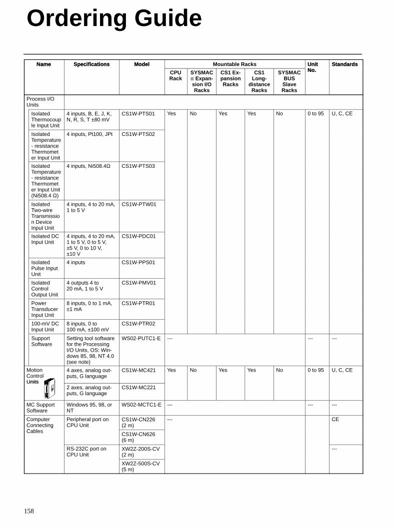
Ordering Guide
158
Name StandardsUnitNo.
Mountable RacksModelSpecificationsName StandardsUnitNo.SYSMAC
BUSSlaveRacks
CS1Long-
distanceRacks
CS1 Ex-pansionRacks
SYSMACα Expan -sion I/ORacks
CPURack
ModelSpecifications
Process I/OUnits
IsolatedThermocouple Input Unit
4 inputs, B, E, J, K,N, R, S, T ±80 mV
CS1W-PTS01 Yes No Yes Yes No 0 to 95 U, C, CE
IsolatedTemperature- resistanceThermometer Input Unit
4 inputs, Pt100, JPt CS1W-PTS02
IsolatedTemperature- resistanceThermometer Input Unit(Ni508.4 Ω)
4 inputs, Ni508.4Ω CS1W-PTS03
IsolatedTwo-wireTransmission DeviceInput Unit
4 inputs, 4 to 20 mA,1 to 5 V
CS1W-PTW01
Isolated DCInput Unit
4 inputs, 4 to 20 mA,1 to 5 V, 0 to 5 V,±5 V, 0 to 10 V,±10 V
CS1W-PDC01
IsolatedPulse InputUnit
4 inputs CS1W-PPS01
IsolatedControlOutput Unit
4 outputs 4 to20 mA, 1 to 5 V
CS1W-PMV01
PowerTransducerInput Unit
8 inputs, 0 to 1 mA,±1 mA
CS1W-PTR01
100-mV DCInput Unit
8 inputs, 0 to100 mA, ±100 mV
CS1W-PTR02
SupportSoftware
Setting tool softwarefor the ProcessingI/O Units, OS: Win-dows 85, 98, NT 4.0(see note)
WS02-PUTC1-E --- --- ---
MotionControlUnits
4 axes, analog out-puts, G language
CS1W-MC421 Yes No Yes Yes No 0 to 95 U, C, CE
Units2 axes, analog out-puts, G language
CS1W-MC221
MC SupportSoftware
Windows 95, 98, orNT
WS02-MCTC1-E --- --- ---
ComputerConnectingC bl
Peripheral port onCPU Unit
CS1W-CN226(2 m)
--- CEg
Cables CS1W-CN626(6 m)
RS-232C port onCPU Unit
XW2Z-200S-CV(2 m)
---
XW2Z-500S-CV(5 m)
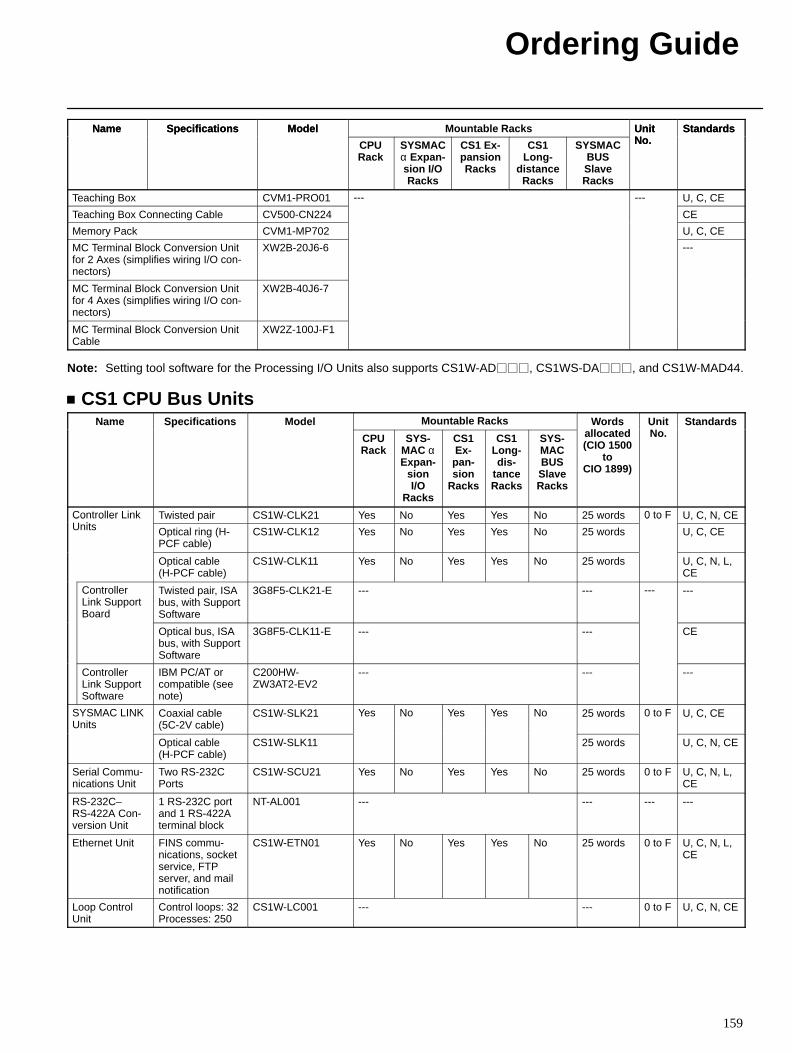
Ordering Guide
159
Name StandardsUnitNo.
Mountable RacksModelSpecificationsName StandardsUnitNo.SYSMAC
BUSSlaveRacks
CS1Long-
distanceRacks
CS1 Ex-pansionRacks
SYSMACα Expan -sion I/ORacks
CPURack
ModelSpecifications
Teaching Box CVM1-PRO01 --- --- U, C, CE
Teaching Box Connecting Cable CV500-CN224 CE
Memory Pack CVM1-MP702 U, C, CE
MC Terminal Block Conversion Unitfor 2 Axes (simplifies wiring I/O con-nectors)
XW2B-20J6-6 ---
MC Terminal Block Conversion Unitfor 4 Axes (simplifies wiring I/O con-nectors)
XW2B-40J6-7
MC Terminal Block Conversion UnitCable
XW2Z-100J-F1
Note: Setting tool software for the Processing I/O Units also supports CS1W-AD, CS1WS-DA, and CS1W-MAD44.
CS1 CPU Bus UnitsName Specifications Model Mountable Racks Words
ll t dUnitN
Standardsa e Spec ca o s ode
CPURack
SYS-MAC αExpan-
sionI/O
Racks
CS1Ex-pan-sion
Racks
CS1Long-dis-
tanceRacks
SYS-MACBUSSlaveRacks
o dsallocated(CIO 1500
toCIO 1899)
UNo.
S a da ds
Controller LinkU it
Twisted pair CS1W-CLK21 Yes No Yes Yes No 25 words 0 to F U, C, N, CECo o eUnits Optical ring (H-
PCF cable)CS1W-CLK12 Yes No Yes Yes No 25 words
0 o
U, C, CE
Optical cable(H-PCF cable)
CS1W-CLK11 Yes No Yes Yes No 25 words U, C, N, L,CE
ControllerLink SupportBoard
Twisted pair, ISAbus, with SupportSoftware
3G8F5-CLK21-E --- --- --- ---
Optical bus, ISAbus, with SupportSoftware
3G8F5-CLK11-E --- --- CE
ControllerLink SupportSoftware
IBM PC/AT orcompatible (seenote)
C200HW-ZW3AT2-EV2
--- --- ---
SYSMAC LINKUnits
Coaxial cable(5C-2V cable)
CS1W-SLK21 Yes No Yes Yes No 25 words 0 to F U, C, CE
Optical cable (H-PCF cable)
CS1W-SLK11 25 words U, C, N, CE
Serial Commu-nications Unit
Two RS-232CPorts
CS1W-SCU21 Yes No Yes Yes No 25 words 0 to F U, C, N, L,CE
RS-232C–RS-422A Con-version Unit
1 RS-232C portand 1 RS-422Aterminal block
NT-AL001 --- --- --- ---
Ethernet Unit FINS commu-nications, socketservice, FTPserver, and mailnotification
CS1W-ETN01 Yes No Yes Yes No 25 words 0 to F U, C, N, L,CE
Loop ControlUnit
Control loops: 32Processes: 250
CS1W-LC001 --- --- 0 to F U, C, N, CE
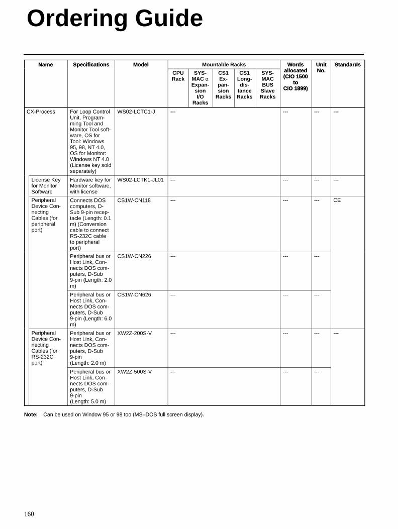
Ordering Guide
160
Name StandardsUnitNo.
Wordsallocated(CIO 1500
toCIO 1899)
Mountable RacksModelSpecificationsName StandardsUnitNo.
Wordsallocated(CIO 1500
toCIO 1899)
SYS-MACBUSSlaveRacks
CS1Long-dis-
tanceRacks
CS1Ex-pan-sion
Racks
SYS-MAC αExpan-
sionI/O
Racks
CPURack
ModelSpecifications
CX-Process For Loop ControlUnit, Program-ming Tool andMonitor Tool soft-ware, OS forTool: Windows95, 98, NT 4.0,OS for Monitor:Windows NT 4.0(License key soldseparately)
WS02-LCTC1-J --- --- --- ---
License Keyfor MonitorSoftware
Hardware key forMonitor software,with license
WS02-LCTK1-JL01 --- --- --- ---
PeripheralDevice Con-nectingCables (forperipheralport)
Connects DOScomputers, D-Sub 9-pin recep-tacle (Length: 0.1m) (Conversioncable to connectRS-232C cableto peripheralport)
CS1W-CN118 --- --- --- CE
Peripheral bus orHost Link, Con-nects DOS com-puters, D-Sub9-pin (Length: 2.0m)
CS1W-CN226 --- --- ---
Peripheral bus orHost Link, Con-nects DOS com-puters, D-Sub9-pin (Length: 6.0m)
CS1W-CN626 --- --- ---
PeripheralDevice Con-nectingCables (forRS-232Cport)
Peripheral bus orHost Link, Con-nects DOS com-puters, D-Sub9-pin (Length: 2.0 m)
XW2Z-200S-V --- --- --- ---
)
Peripheral bus orHost Link, Con-nects DOS com-puters, D-Sub9-pin (Length: 5.0 m)
XW2Z-500S-V --- --- ---
Note: Can be used on Window 95 or 98 too (MS–DOS full screen display).
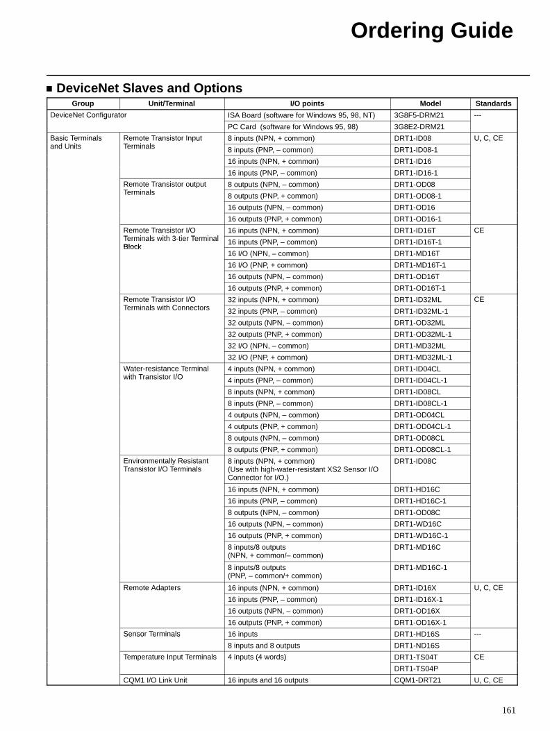
Ordering Guide
161
DeviceNet Slaves and OptionsGroup Unit/Terminal I/O points Model Standards
DeviceNet Configurator ISA Board (software for Windows 95, 98, NT) 3G8F5-DRM21 ---e ce e Co gu a o
PC Card (software for Windows 95, 98) 3G8E2-DRM21
Basic Terminalsd U it
Remote Transistor InputT i l
8 inputs (NPN, + common) DRT1-ID08 U, C, CEas c e a sand Units
e o e a s s o uTerminals 8 inputs (PNP, – common) DRT1-ID08-1
U, C, C
16 inputs (NPN, + common) DRT1-ID16
16 inputs (PNP, – common) DRT1-ID16-1
Remote Transistor outputT i l
8 outputs (NPN, – common) DRT1-OD08e o e a s s o ou uTerminals 8 outputs (PNP, + common) DRT1-OD08-1
16 outputs (NPN, – common) DRT1-OD16
16 outputs (PNP, + common) DRT1-OD16-1
Remote Transistor I/OT i l ith 3 ti T i l
16 inputs (NPN, + common) DRT1-ID16T CEe o e a s s o /OTerminals with 3-tier TerminalBlock
16 inputs (PNP, – common) DRT1-ID16T-1
C
Block16 I/O (NPN, – common) DRT1-MD16T
16 I/O (PNP, + common) DRT1-MD16T-1
16 outputs (NPN, – common) DRT1-OD16T
16 outputs (PNP, + common) DRT1-OD16T-1
Remote Transistor I/OT i l ith C t
32 inputs (NPN, + common) DRT1-ID32ML CEe o e a s s o /OTerminals with Connectors 32 inputs (PNP, – common) DRT1-ID32ML-1
C
32 outputs (NPN, – common) DRT1-OD32ML
32 outputs (PNP, + common) DRT1-OD32ML-1
32 I/O (NPN, – common) DRT1-MD32ML
32 I/O (PNP, + common) DRT1-MD32ML-1
Water-resistance Terminalith T i t I/O
4 inputs (NPN, + common) DRT1-ID04CLa e es s a ce e awith Transistor I/O 4 inputs (PNP, – common) DRT1-ID04CL-1
8 inputs (NPN, + common) DRT1-ID08CL
8 inputs (PNP, – common) DRT1-ID08CL-1
4 outputs (NPN, – common) DRT1-OD04CL
4 outputs (PNP, + common) DRT1-OD04CL-1
8 outputs (NPN, – common) DRT1-OD08CL
8 outputs (PNP, + common) DRT1-OD08CL-1
Environmentally ResistantTransistor I/O Terminals
8 inputs (NPN, + common) (Use with high-water-resistant XS2 Sensor I/OConnector for I/O.)
DRT1-ID08C
16 inputs (NPN, + common) DRT1-HD16C
16 inputs (PNP, – common) DRT1-HD16C-1
8 outputs (NPN, – common) DRT1-OD08C
16 outputs (NPN, – common) DRT1-WD16C
16 outputs (PNP, + common) DRT1-WD16C-1
8 inputs/8 outputs(NPN, + common/– common)
DRT1-MD16C
8 inputs/8 outputs(PNP, – common/+ common)
DRT1-MD16C-1
Remote Adapters 16 inputs (NPN, + common) DRT1-ID16X U, C, CEe o e da e s
16 inputs (PNP, – common) DRT1-ID16X-1
U, C, C
16 outputs (NPN, – common) DRT1-OD16X
16 outputs (PNP, + common) DRT1-OD16X-1
Sensor Terminals 16 inputs DRT1-HD16S ---Se so e a s
8 inputs and 8 outputs DRT1-ND16S
Temperature Input Terminals 4 inputs (4 words) DRT1-TS04T CEe e a u e u e a s u s ( o ds)
DRT1-TS04P
C
CQM1 I/O Link Unit 16 inputs and 16 outputs CQM1-DRT21 U, C, CE
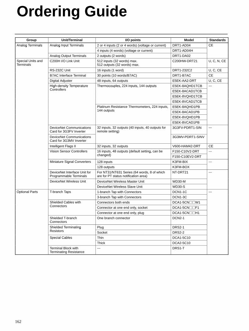
Ordering Guide
162
Group StandardsModelI/O pointsUnit/Terminal
Analog Terminals Analog Input Terminals 2 or 4 inputs (2 or 4 words) (voltage or current) DRT1-AD04 CEa og e a s a og u e a s
4 inputs (4 words) (voltage or current) DRT1-AD04H
C
Analog Output Terminals 2 outputs (2 words) DRT1-DA02
Special Units andTerminals
C200H I/O Link Unit 512 inputs (32 words) max. 512 outputs (32 words) max.
C200HW-DRT21 U, C, N, CE
RS-232C Unit 16 inputs (1 word) DRT1-232C2 U, C, CE
B7AC Interface Terminal 30 points (10 words/B7AC) DRT1-B7AC CE
Digital Adjuster 48 inputs, 64 outputs E5EK-AA2-DRT U, C, CE
High-density TemperatureC t ll
Thermocouples, 224 inputs, 144 outputs E5EK-8AQHD1TCB ---g de s y e e a u eControllers
e ocou es, u s, ou u s
E5EK-8ACAD1TCB
E5EK-8VQHD1TCB
E5EK-8VCAD1TCB
Platinum Resistance Thermometers, 224 inputs,144 t t
E5EK-8AQHD1PBa u es s a ce e o e e s, u s,144 outputs E5EK-8ACAD1PB
E5EK-8VQHD1PB
E5EK-8VCAD1PB
DeviceNet CommunicationsCard for 3G3FV Inverter
32 inputs, 32 outputs (40 inputs, 40 outputs forremote setting)
3G3FV-PDRT1-SIN ---
DeviceNet CommunicationsCard for 3G3MV Inverter
g)
3G3MV-PDRT1-SINV
Intelligent Flags II 32 inputs, 32 outputs V600-HAM42-DRT CE
Vision Sensor Controllers 16 inputs, 48 outputs (default setting, can beh d)
F150-C10V2-DRT ---s o Se so Co o e s 6 u s, 8 ou u s (de au se g, ca bechanged) F150-C10EV2-DRT
Miniature Signal Converters 128 inputs K3FM-BIX ---a u e S g a Co e e s
128 outputs K3FM-BOX
DeviceNet Interface Unit forProgrammable Terminals
For NT31/NT631 Series (64 words, 8 of whichare for PT status notification area)
NT-DRT21 ---
DeviceNet Wireless Unit DeviceNet Wireless Master Unit WD30-Me ce e e ess U
DeviceNet Wireless Slave Unit WD30-S
Optional Parts T-branch Taps 1-branch Tap with Connectors DCN1-1C ---O o a a s b a c a s
3-branch Tap with Connectors DCN1-3C
Shielded Cables withC t
Connectors both ends DCA1-5CNW1S e ded Cab esConnectors Connector at one end only, socket DCA1-5CNF1
Connector at one end only, plug DCA1-5CNH1
Shielded T-branchConnectors
One branch connector DCN2-1
Shielded TerminatingR i t
Plug DRS2-1S e ded e a gResistors Socket DRS2-2
Special Cables Thin DCA1-5C10S ec a Cab es
Thick DCA2-5C10
Terminal Block withTerminating Resistance
--- DRS1-T
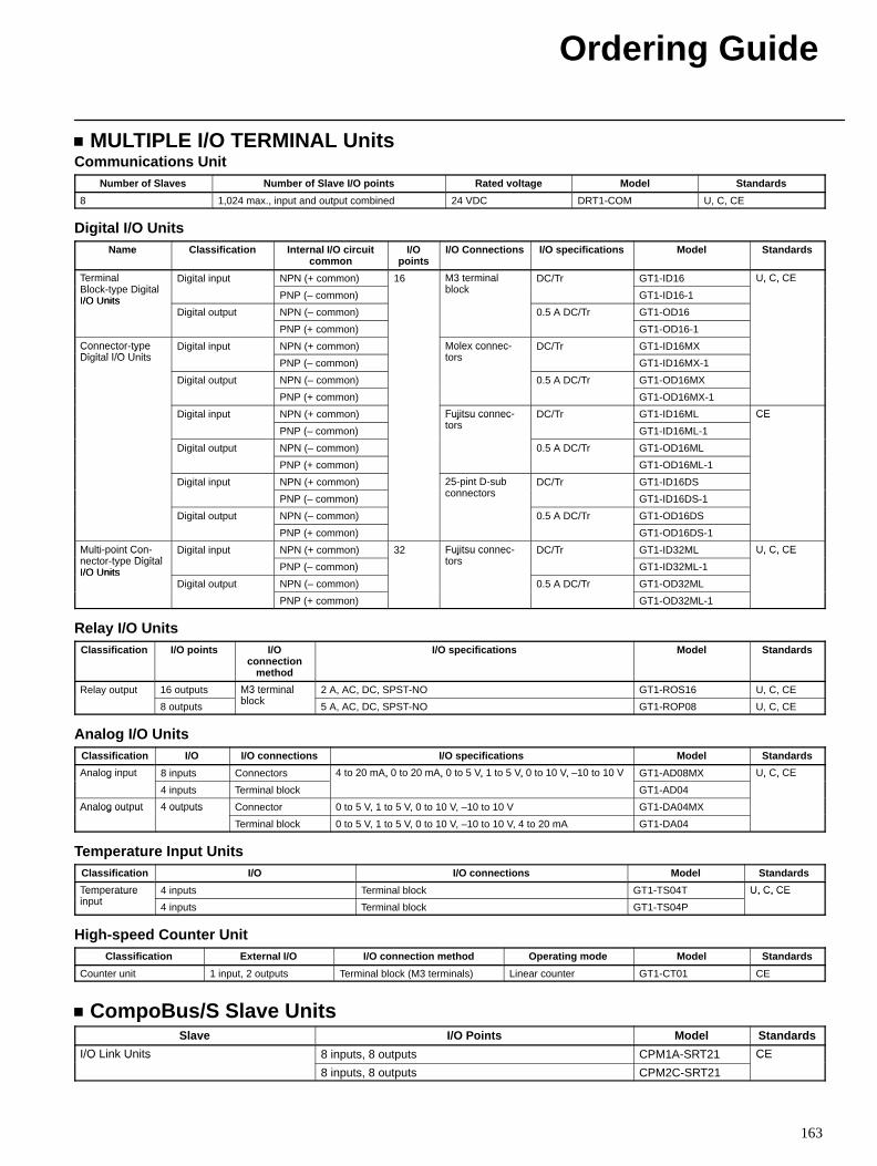
Ordering Guide
163
MULTIPLE I/O TERMINAL UnitsCommunications Unit
Number of Slaves Number of Slave I/O points Rated voltage Model Standards
8 1,024 max., input and output combined 24 VDC DRT1-COM U, C, CE
Digital I/O UnitsName Classification Internal I/O circuit
commonI/O
pointsI/O Connections I/O specifications Model Standards
TerminalBl k t Di it l
Digital input NPN (+ common) 16 M3 terminalbl k
DC/Tr GT1-ID16 U, C, CETerminalBlock-type DigitalI/O Units PNP (– common)
M3 terminalblock GT1-ID16-1
U, C, CE
I/O UnitsDigital output NPN (– common) 0.5 A DC/Tr GT1-OD16
PNP (+ common) GT1-OD16-1
Connector-typeDi it l I/O U it
Digital input NPN (+ common) Molex connec-t
DC/Tr GT1-ID16MXConnector ty eDigital I/O Units PNP (– common)
Molex connectors GT1-ID16MX-1
Digital output NPN (– common) 0.5 A DC/Tr GT1-OD16MX
PNP (+ common) GT1-OD16MX-1
Digital input NPN (+ common) Fujitsu connec-t
DC/Tr GT1-ID16ML CE
PNP (– common)
Fujitsu connectors GT1-ID16ML-1
CE
Digital output NPN (– common) 0.5 A DC/Tr GT1-OD16ML
PNP (+ common) GT1-OD16ML-1
Digital input NPN (+ common) 25-pint D-subt
DC/Tr GT1-ID16DS
PNP (– common)
25 int D subconnectors GT1-ID16DS-1
Digital output NPN (– common) 0.5 A DC/Tr GT1-OD16DS
PNP (+ common) GT1-OD16DS-1
Multi-point Con-t t Di it l
Digital input NPN (+ common) 32 Fujitsu connec-t
DC/Tr GT1-ID32ML U, C, CEMulti oint Connector-type DigitalI/O Units PNP (– common)
Fujitsu connectors GT1-ID32ML-1
U, C, CE
I/O UnitsDigital output NPN (– common) 0.5 A DC/Tr GT1-OD32ML
PNP (+ common) GT1-OD32ML-1
Relay I/O UnitsClassification I/O points I/O
connectionmethod
I/O specifications Model Standards
Relay output 16 outputs M3 terminalbl k
2 A, AC, DC, SPST-NO GT1-ROS16 U, C, CE
8 outputs
M3 terminalblock 5 A, AC, DC, SPST-NO GT1-ROP08 U, C, CE
Analog I/O UnitsClassification I/O I/O connections I/O specifications Model Standards
Analog input 8 inputs Connectors 4 to 20 mA, 0 to 20 mA, 0 to 5 V, 1 to 5 V, 0 to 10 V, –10 to 10 V GT1-AD08MX U, C, CEAnalog in ut
4 inputs Terminal block
4 to 20 mA, 0 to 20 mA, 0 to 5 V, 1 to 5 V, 0 to 10 V, 10 to 10 V
GT1-AD04
U, C, CE
Analog output 4 outputs Connector 0 to 5 V, 1 to 5 V, 0 to 10 V, –10 to 10 V GT1-DA04MXAnalog out ut 4 out uts
Terminal block 0 to 5 V, 1 to 5 V, 0 to 10 V, –10 to 10 V, 4 to 20 mA GT1-DA04
Temperature Input UnitsClassification I/O I/O connections Model Standards
Temperaturei t
4 inputs Terminal block GT1-TS04T U, C, CETem eratureinput 4 inputs Terminal block GT1-TS04P
U, C, CE
High-speed Counter UnitClassification External I/O I/O connection method Operating mode Model Standards
Counter unit 1 input, 2 outputs Terminal block (M3 terminals) Linear counter GT1-CT01 CE
CompoBus/S Slave UnitsSlave I/O Points Model Standards
I/O Link Units 8 inputs, 8 outputs CPM1A-SRT21 CE/O U s
8 inputs, 8 outputs CPM2C-SRT21
C
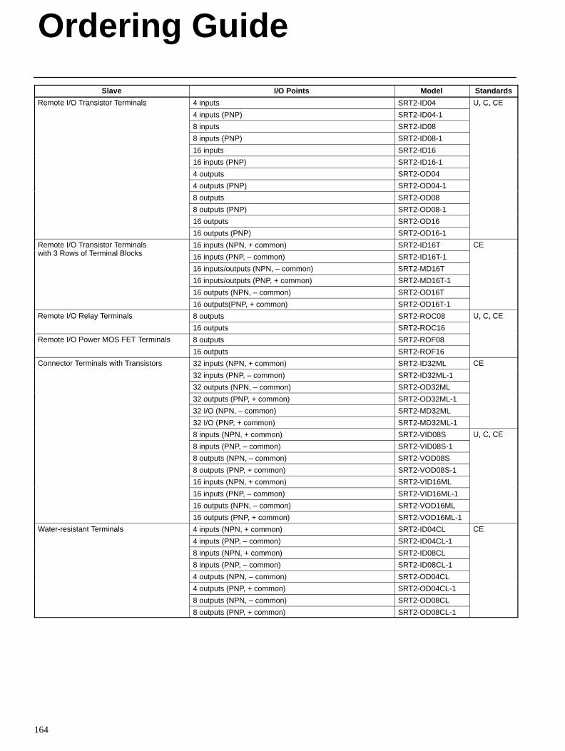
Ordering Guide
164
Slave StandardsModelI/O Points
Remote I/O Transistor Terminals 4 inputs SRT2-ID04 U, C, CEe o e /O a s s o e a s
4 inputs (PNP) SRT2-ID04-1
U, C, C
8 inputs SRT2-ID08
8 inputs (PNP) SRT2-ID08-1
16 inputs SRT2-ID16
16 inputs (PNP) SRT2-ID16-1
4 outputs SRT2-OD04
4 outputs (PNP) SRT2-OD04-1
8 outputs SRT2-OD08
8 outputs (PNP) SRT2-OD08-1
16 outputs SRT2-OD16
16 outputs (PNP) SRT2-OD16-1
Remote I/O Transistor Terminals ith 3 R f T i l Bl k
16 inputs (NPN, + common) SRT2-ID16T CEe o e /O a s s o e a swith 3 Rows of Terminal Blocks 16 inputs (PNP, – common) SRT2-ID16T-1
C
16 inputs/outputs (NPN, – common) SRT2-MD16T
16 inputs/outputs (PNP, + common) SRT2-MD16T-1
16 outputs (NPN, – common) SRT2-OD16T
16 outputs(PNP, + common) SRT2-OD16T-1
Remote I/O Relay Terminals 8 outputs SRT2-ROC08 U, C, CEe o e /O e ay e a s
16 outputs SRT2-ROC16
U, C, C
Remote I/O Power MOS FET Terminals 8 outputs SRT2-ROF08e o e /O o e OS e a s
16 outputs SRT2-ROF16
Connector Terminals with Transistors 32 inputs (NPN, + common) SRT2-ID32ML CECo ec o e a s a s s o s
32 inputs (PNP, – common) SRT2-ID32ML-1
C
32 outputs (NPN, – common) SRT2-OD32ML
32 outputs (PNP, + common) SRT2-OD32ML-1
32 I/O (NPN, – common) SRT2-MD32ML
32 I/O (PNP, + common) SRT2-MD32ML-1
8 inputs (NPN, + common) SRT2-VID08S U, C, CE
8 inputs (PNP, – common) SRT2-VID08S-1
U, C, C
8 outputs (NPN, – common) SRT2-VOD08S
8 outputs (PNP, + common) SRT2-VOD08S-1
16 inputs (NPN, + common) SRT2-VID16ML
16 inputs (PNP, – common) SRT2-VID16ML-1
16 outputs (NPN, – common) SRT2-VOD16ML
16 outputs (PNP, + common) SRT2-VOD16ML-1
Water-resistant Terminals 4 inputs (NPN, + common) SRT2-ID04CL CEa e es s a e a s
4 inputs (PNP, – common) SRT2-ID04CL-1
C
8 inputs (NPN, + common) SRT2-ID08CL
8 inputs (PNP, – common) SRT2-ID08CL-1
4 outputs (NPN, – common) SRT2-OD04CL
4 outputs (PNP, + common) SRT2-OD04CL-1
8 outputs (NPN, – common) SRT2-OD08CL
8 outputs (PNP, + common) SRT2-OD08CL-1
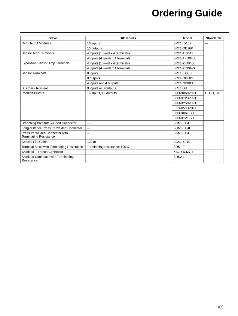
Ordering Guide
165
Slave StandardsModelI/O Points
Remote I/O Modules 16 inputs SRT1-ID16P ---e o e /O odu es
16 outputs SRT1-OD16P
Sensor Amp Terminals 4 inputs (1 word x 4 terminals) SRT1-TID04SSe so e a s
4 inputs (4 words x 1 terminal) SRT1-TKD04S
Expansion Sensor Amp Terminals 4 inputs (1 word x 4 terminals) SRT1-XID04Sa s o Se so e a s
4 inputs (4 words x 1 terminal) SRT1-XKD04S
Sensor Terminals 8 inputs SRT1-ID08SSe so e a s
8 outputs SRT1-OD08S
4 inputs and 4 outputs SRT1-ND08S
Bit Chain Terminal 8 inputs or 8 outputs SRT1-BIT
Position Drivers 16 inputs, 16 outputs FND-X06H-SRT U, CU, CEos o e s 6 u s, 6 ou u s
FND-X12H-SRT
U, CU, C
FND-X25H-SRT
FXD-X50H-SRT
FND-X06L-SRT
FND-X12L-SRT
Branching Pressure-welded Connector --- SCN1-TH4 ---
Long-distance Pressure-welded Connector --- SCN1-TH4E
Pressure-welded Connector withTerminating Resistance
--- SCN1-TH4T
Special Flat Cable 100 m SCA1-4F10
Terminal Block with Terminating Resistance Terminating resistance: 100 Ω SRS1-T
Shielded T-branch Connector --- XS2R-D427-5 ---
Shielded Connector with TerminatingResistance
--- SRS2-1
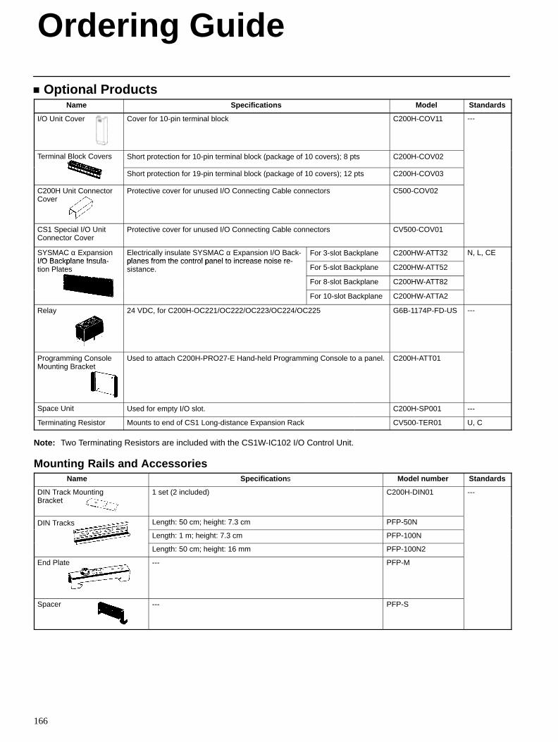
Ordering Guide
166
Optional ProductsName Specifications Model Standards
I/O Unit Cover Cover for 10-pin terminal block C200H-COV11 ---
Terminal Block Covers Short protection for 10-pin terminal block (package of 10 covers); 8 pts C200H-COV02
Short protection for 19-pin terminal block (package of 10 covers); 12 pts C200H-COV03
C200H Unit ConnectorCover
Protective cover for unused I/O Connecting Cable connectors C500-COV02
CS1 Special I/O Unit Connector Cover
Protective cover for unused I/O Connecting Cable connectors CV500-COV01
SYSMAC α ExpansionI/O Backplane Insula-
Electrically insulate SYSMAC α Expansion I/O Back-planes from the control panel to increase noise re-
For 3-slot Backplane C200HW-ATT32 N, L, CEI/O Backplane Insula-tion Plates
planes from the control panel to increase noise re-sistance. For 5-slot Backplane C200HW-ATT52
For 8-slot Backplane C200HW-ATT82
For 10-slot Backplane C200HW-ATTA2
Relay 24 VDC, for C200H-OC221/OC222/OC223/OC224/OC225 G6B-1174P-FD-US ---
Programming Console Mounting Bracket
Used to attach C200H-PRO27-E Hand-held Programming Console to a panel. C200H-ATT01
Space Unit Used for empty I/O slot. C200H-SP001 ---
Terminating Resistor Mounts to end of CS1 Long-distance Expansion Rack CV500-TER01 U, C
Note: Two Terminating Resistors are included with the CS1W-IC102 I/O Control Unit.
Mounting Rails and AccessoriesName Specification s Model number Standards
DIN Track MountingBracket
1 set (2 included) C200H-DIN01 ---
DIN Tracks Length: 50 cm; height: 7.3 cm PFP-50N
Length: 1 m; height: 7.3 cm PFP-100N
Length: 50 cm; height: 16 mm PFP-100N2
End Plate --- PFP-M
Spacer --- PFP-S
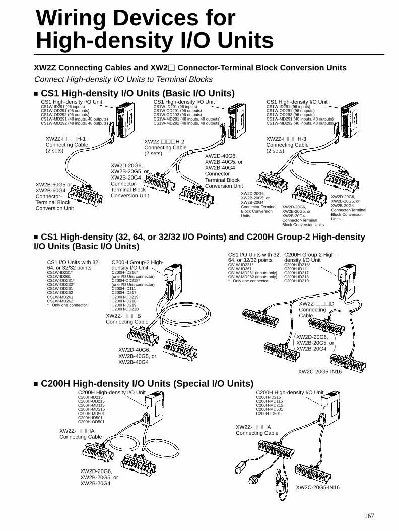
167
XW2Z Connecting Cables and XW2 Connector-Terminal Block Conversion UnitsConnect High-density I/O Units to Terminal Blocks
CS1 High-density I/O Units (Basic I/O Units)CS1 High-density I/O UnitCS1W-ID291 (96 inputs)CS1W-OD291 (96 outputs)CS1W-OD292 (96 outputs)CS1W-MD291 (48 inputs, 48 outputs)CS1W-MD292 (48 inputs, 48 outputs)
XW2Z-H-1Connecting Cable(2 sets)
XW2B-60G5 orXW2B-60G4Connector-Terminal BlockConversion Unit
CS1 High-density I/O UnitCS1W-ID291 (96 inputs)CS1W-OD291 (96 outputs)CS1W-OD292 (96 outputs)CS1W-MD291 (48 inputs, 48 outputs)CS1W-MD292 (48 inputs, 48 outputs)
CS1 High-density I/O UnitCS1W-ID291 (96 inputs)CS1W-OD291 (96 outputs)CS1W-OD292 (96 outputs)CS1W-MD291 (48 inputs, 48 outputs)CS1W-MD292 (48 inputs, 48 outputs)
XW2D-20G6,XW2B-20G5, orXW2B-20G4Connector-Terminal BlockConversion Unit
XW2D-40G6,XW2B-40G5, orXW2B-40G4Connector-Terminal BlockConversion Unit
XW2D-20G6,XW2B-20G5, orXW2B-20G4Connector-TerminalBlock ConversionUnits
XW2Z-H-2Connecting Cable(2 sets)
XW2Z-H-3Connecting Cable(2 sets)
XW2D-20G6,XW2B-20G5, orXW2B-20G4Connector-TerminalBlock Conversion Units
XW2D-20G6,XW2B-20G5, orXW2B-20G4Connector-TerminalBlock ConversionUnits
CS1 High-density (32, 64, or 32/32 I/O Points) and C200H Group-2 High-densityI/O Units (Basic I/O Units)
C200H Group-2 High-density I/O UnitC200H-ID216* (one I/O Unit connector)C200H-OD218* (one I/O Unit connector)C200H-ID111C200H-ID217C200H-OD219C200H-ID218C200H-ID219C200H-OD21B
XW2Z-BConnecting Cable
XW2D-40G6,XW2B-40G5, orXW2B-40G4
C200H Group-2 High-density I/O UnitC200H-ID216*C200H-ID111C200H-ID217C200H-ID218C200H-ID219
XW2Z-DConnectingCable
CS1 I/O Units with 32,64, or 32/32 pointsCS1W-ID231*CS1W-ID261CS1W-MD261 (inputs only)CS1W-MD262 (inputs only)* Only one connector.
CS1 I/O Units with 32,64, or 32/32 pointsCS1W-ID231*CS1W-ID261CS1W-OD231*CS1W-OD232*CS1W-OD261CS1W-OD262CS1W-MD261CS1W-MD262* Only one connector.
XW2D-20G6,XW2B-20G5, orXW2B-20G4
XW2C-20G5-IN16
C200H High-density I/O Units (Special I/O Units)C200H High-density I/O UnitC200H-ID215C200H-OD215C200H-MD115C200H-MD215C200H-MD501C200H-ID501C200H-OD501
XW2Z-AConnecting Cable
XW2D-20G6,XW2B-20G5, orXW2B-20G4
XW2C-20G5-IN16
XW2Z-AConnecting Cable
C200H High-density I/O UnitC200H-ID215C200H-MD115C200H-MD215C200H-MD501C200H-ID501
Wiring Devices forHigh-density I/O Units
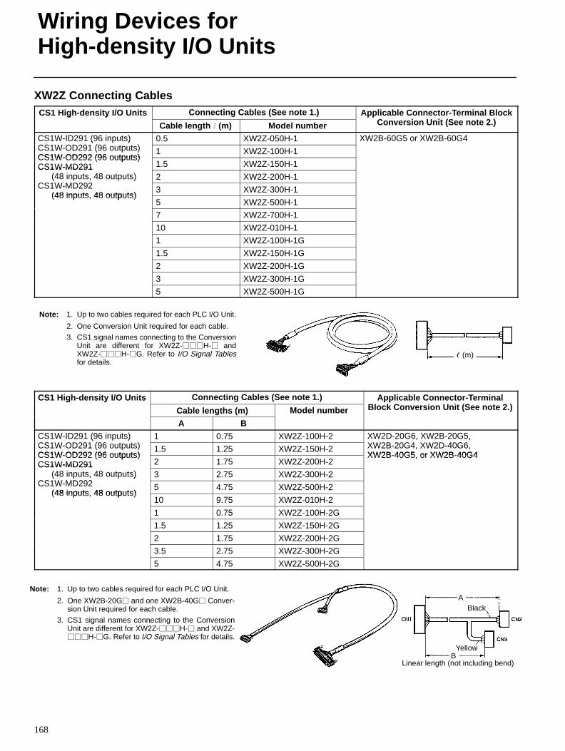
Wiring Devices forHigh-density I/O Units
168
XW2Z Connecting CablesCS1 High-density I/O Units Connecting Cables (See note 1.) Applicable Connector-Terminal Block
C i U i (S 2 )g y
Cable length l (m) Model number
ppConversion Unit (See note 2.)
CS1W-ID291 (96 inputs)CS1W OD291 (96 )
0.5 XW2Z-050H-1 XW2B-60G5 or XW2B-60G4( )CS1W-OD291 (96 outputs)CS1W-OD292 (96 outputs)
1 XW2Z-100H-1CS1W-OD292 (96 outputs)CS1W-MD291 1.5 XW2Z-150H-1CS1W-MD291
(48 inputs, 48 outputs)CS1W MD292
2 XW2Z-200H-1( , )CS1W-MD292
(48 inputs 48 outputs)3 XW2Z-300H-1
(48 inputs, 48 outputs)5 XW2Z-500H-1
7 XW2Z-700H-1
10 XW2Z-010H-1
1 XW2Z-100H-1G
1.5 XW2Z-150H-1G
2 XW2Z-200H-1G
3 XW2Z-300H-1G
5 XW2Z-500H-1G
(m)
Note: 1. Up to two cables required for each PLC I/O Unit.
2. One Conversion Unit required for each cable.
3. CS1 signal names connecting to the ConversionUnit are different for XW2Z-H- andXW2Z-H-G. Refer to I/O Signal Tablesfor details.
CS1 High-density I/O Units Connecting Cables (See note 1.) Applicable Connector-TerminalBl k C i U i (S 2 )
g y
Cable lengths (m) Model number
ppBlock Conversion Unit (See note 2.)
A BCS1W-ID291 (96 inputs)CS1W OD291 (96 )
1 0.75 XW2Z-100H-2 XW2D-20G6, XW2B-20G5,XW2B 20G4 XW2D 40G6
( )CS1W-OD291 (96 outputs)CS1W-OD292 (96 outputs)
1.5 1.25 XW2Z-150H-2
, ,XW2B-20G4, XW2D-40G6,XW2B-40G5 or XW2B-40G4CS1W-OD292 (96 outputs)
CS1W-MD291 2 1.75 XW2Z-200H-2XW2B-40G5, or XW2B-40G4
CS1W-MD291 (48 inputs, 48 outputs)
CS1W MD2923 2.75 XW2Z-300H-2( , )
CS1W-MD292 (48 inputs 48 outputs)
5 4.75 XW2Z-500H-2(48 inputs, 48 outputs)
10 9.75 XW2Z-010H-2
1 0.75 XW2Z-100H-2G
1.5 1.25 XW2Z-150H-2G
2 1.75 XW2Z-200H-2G
3.5 2.75 XW2Z-300H-2G
5 4.75 XW2Z-500H-2G
ABlack
BYellow
Linear length (not including bend)
Note: 1. Up to two cables required for each PLC I/O Unit.
2. One XW2B-20G and one XW2B-40G Conver-sion Unit required for each cable.
3. CS1 signal names connecting to the ConversionUnit are different for XW2Z-H- and XW2Z-H-G. Refer to I/O Signal Tables for details.
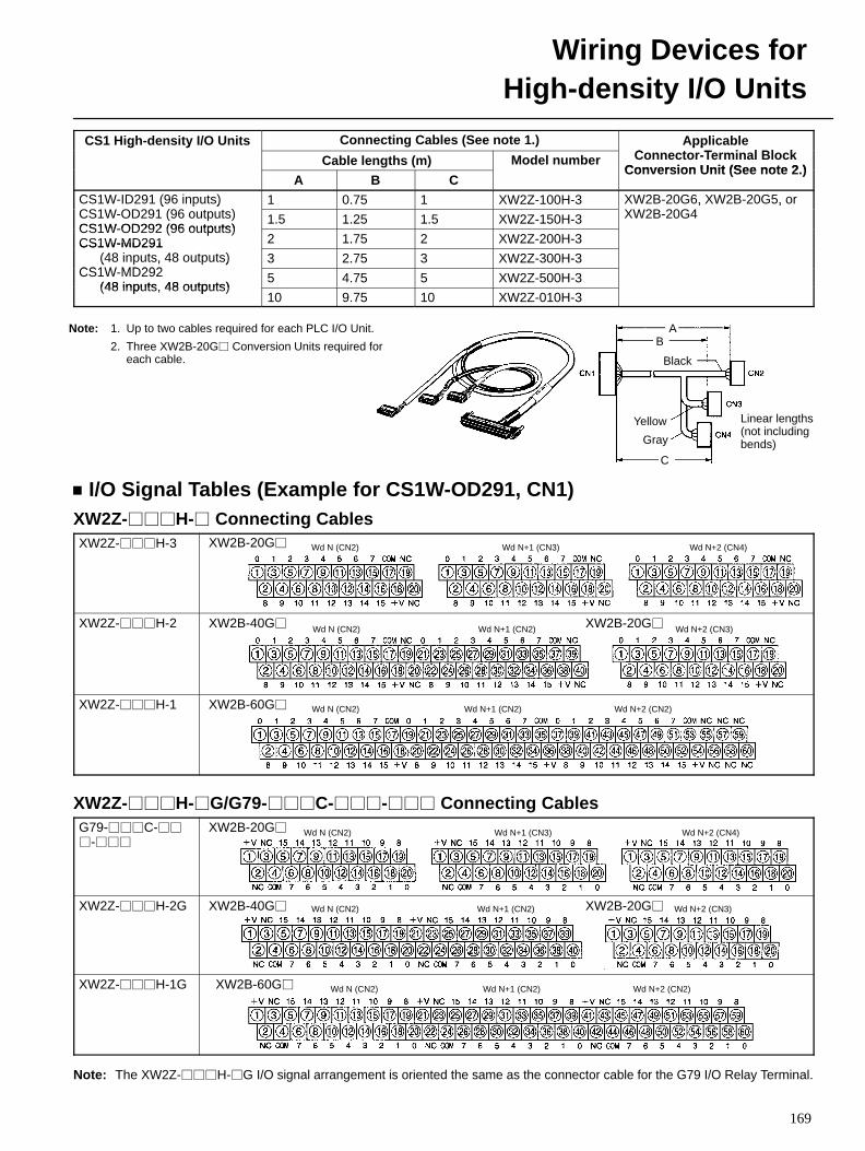
Wiring Devices forHigh-density I/O Units
169
CS1 High-density I/O Units Connecting Cables (See note 1.) ApplicableC T i l Bl k
g y
Cable lengths (m) Model number
ppConnector-Terminal Block
Conversion Unit (See note 2 )A B C
Convers ion Unit (See note 2.)
CS1W-ID291 (96 inputs)CS1W OD291 (96 )
1 0.75 1 XW2Z-100H-3 XW2B-20G6, XW2B-20G5, orXW2B 20G4
( )CS1W-OD291 (96 outputs)CS1W-OD292 (96 outputs)
1.5 1.25 1.5 XW2Z-150H-3
, ,XW2B-20G4
CS1W-OD292 (96 outputs)CS1W-MD291 2 1.75 2 XW2Z-200H-3CS1W-MD291
(48 inputs, 48 outputs)CS1W MD292
3 2.75 3 XW2Z-300H-3( , )CS1W-MD292
(48 inputs 48 outputs)5 4.75 5 XW2Z-500H-3
(48 inputs, 48 outputs)10 9.75 10 XW2Z-010H-3
AB
C
Gray
Yellow
Black
Note: 1. Up to two cables required for each PLC I/O Unit.
2. Three XW2B-20G Conversion Units required foreach cable.
Linear lengths(not includingbends)
I/O Signal Tables (Example for CS1W-OD291, CN1)XW2Z-H- Connecting CablesXW2Z-H-3 XW2B-20G Wd N (CN2) Wd N+1 (CN3) Wd N+2 (CN4)
XW2Z-H-2 XW2B-40G XW2B-20GWd N (CN2) Wd N+1 (CN2) Wd N+2 (CN3)
XW2Z-H-1 XW2B-60G Wd N (CN2) Wd N+1 (CN2) Wd N+2 (CN2)
XW2Z-H-G/G79-C-- Connecting CablesG79-C-
-
XW2B-20G Wd N (CN2) Wd N+1 (CN3) Wd N+2 (CN4)
XW2Z-H-2G XW2B-40G XW2B-20GWd N (CN2) Wd N+1 (CN2) Wd N+2 (CN3)
XW2Z-H-1G XW2B-60G Wd N (CN2) Wd N+1 (CN2) Wd N+2 (CN2)
Note: The XW2Z-H-G I/O signal arrangement is oriented the same as the connector cable for the G79 I/O Relay Terminal.
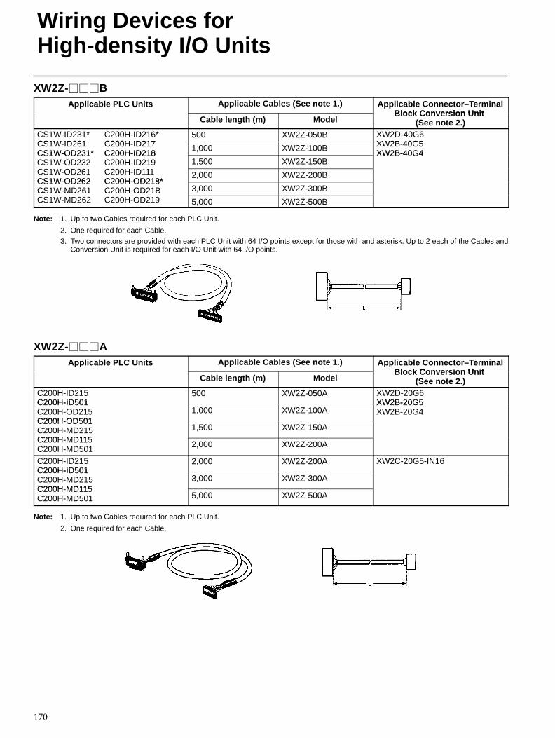
Wiring Devices forHigh-density I/O Units
170
XW2Z-BApplicable PLC Units Applicable Cables (See note 1.) Applicable Connector–Terminal
Block Conversion UnitCable length (m) Model
Block Conversion Unit (See note 2.)
CS1W-ID231* C200H-ID216*CS1W ID261 C200H ID217
500 XW2Z-050B XW2D-40G6XW2B 40G5CS1W-ID261 C200H-ID217
CS1W-OD231* C200H-ID2181,000 XW2Z-100B XW2B-40G5
XW2B-40G4CS1W-OD231* C200H-ID218CS1W-OD232 C200H-ID219CS W OD C H ID
1,500 XW2Z-150BXW2B-40G4
CS O 3 C 00 9CS1W-OD261 C200H-ID111CS1W-OD262 C200H-OD218*
2,000 XW2Z-200BCS1W-OD262 C200H-OD218*CS1W-MD261 C200H-OD21B 3,000 XW2Z-300BCS1W MD261 C200H OD21BCS1W-MD262 C200H-OD219 5,000 XW2Z-500B
Note: 1. Up to two Cables required for each PLC Unit.
2. One required for each Cable.
3. Two connectors are provided with each PLC Unit with 64 I/O points except for those with and asterisk. Up to 2 each of the Cables andConversion Unit is required for each I/O Unit with 64 I/O points.
XW2Z-AApplicable PLC Units Applicable Cables (See note 1.) Applicable Connector–Terminal
Block Conversion UnitCable length (m) Model
Block Conversion Unit (See note 2.)
C200H-ID215C200H-ID501
500 XW2Z-050A XW2D-20G6XW2B-20G5C200H-ID501
C200H-OD215C200H OD501
1,000 XW2Z-100AXW2B-20G5XW2B-20G4
C200H-OD501C200H-MD215C200H MD115
1,500 XW2Z-150A
C200H-MD115C200H-MD501 2,000 XW2Z-200A
C200H-ID215C200H-ID501
2,000 XW2Z-200A XW2C-20G5-IN16C200H-ID501C200H-MD215C200H MD115
3,000 XW2Z-300AC200H-MD115C200H-MD501 5,000 XW2Z-500A
Note: 1. Up to two Cables required for each PLC Unit.
2. One required for each Cable.
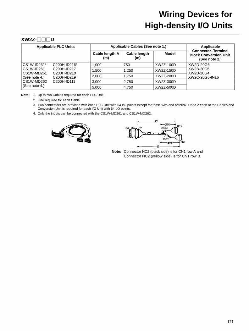
Wiring Devices forHigh-density I/O Units
171
XW2Z-DApplicable PLC Units Applicable Cables (See note 1.) Applicable
Connector TerminalCable length A
(m)Cable length
(m)Model
Connector–TerminalBlock Conversion Unit
(See note 2.)CS1W-ID231* C200H-ID216*CS1W ID261 C200H ID217
1,000 750 XW2Z-100D XW2D-20G6XW2B 20G5CS1W-ID261 C200H-ID217
CS1W-MD261 C200H-ID2181,500 1,250 XW2Z-150D XW2B-20G5
XW2B-20G4CS1W-MD261 C200H-ID218(See note 4.) C200H-ID219 2,000 1,750 XW2Z-200D
XW2B-20G4XW2C-20G5-IN16(See note 4.) C200H-ID219
CS1W-MD262 C200H-ID111(S t 4 )
3,000 2,750 XW2Z-300DXW2C-20G5-IN16
(See note 4.) 5,000 4,750 XW2Z-500D
Note: 1. Up to two Cables required for each PLC Unit.
2. One required for each Cable.
3. Two connectors are provided with each PLC Unit with 64 I/O points except for those with and asterisk. Up to 2 each of the Cables andConversion Unit is required for each I/O Unit with 64 I/O points.
4. Only the inputs can be connected with the CS1W-MD261 and CS1W-MD262.
Note: Connector NC2 (black side) is for CN1 row A andConnector NC2 (yellow side) is for CN1 row B.
Yellow
Black
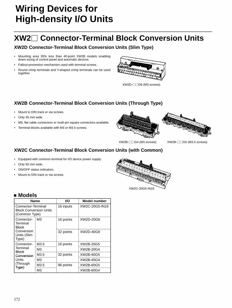
Wiring Devices forHigh-density I/O Units
172
XW2 Connector-Terminal Block Conversion UnitsXW2D Connector-Terminal Block Conversion Units (Slim Type)
• Mounting area 35% less than 40-point XW2B models enablingdown-sizing of control panel and automatic devices.
• Fallout-prevention mechanism used with terminal screws.
• Round crimp terminals and Y-shaped crimp terminals can be usedtogether.
XW2D-G6 (M3 screws)
XW2B Connector-Terminal Block Conversion Units (Through Type)
• Mount to DIN track or via screws.
• Only 45 mm wide.
• MIL flat cable connectors or multi-pin square connectors available.
• Terminal blocks available with M3 or M3.5 screws.
XW2B-G5 (M3.5 screws)XW2B-G4 (M3 screws)
XW2C Connector-Terminal Block Conversion Units (with Common)
• Equipped with common terminal for I/O device power supply.
• Only 50 mm wide.
• ON/OFF status indicators.
• Mount to DIN track or via screws.
XW2C-20G5-IN16
ModelsName I/O Model number
Connector-TerminalBlock Conversion Units(Common Type)
16 inputs XW2C-20G5-IN16
Connector-TerminalBlock
M3 16 points XW2D-20G6
BlockConversionUnits (SlimType)
32 points XW2D-40G6
Connector-T i l
M3.5 16 points XW2B-20G5TerminalBlock
M3 XW2B-20G4BlockConversion M3.5 32 points XW2B-40G5ConversionUnits(Th h
M3 XW2B-40G4(ThroughType)
M3.5 96 points XW2B-60G5Type)
M3 XW2B-60G4
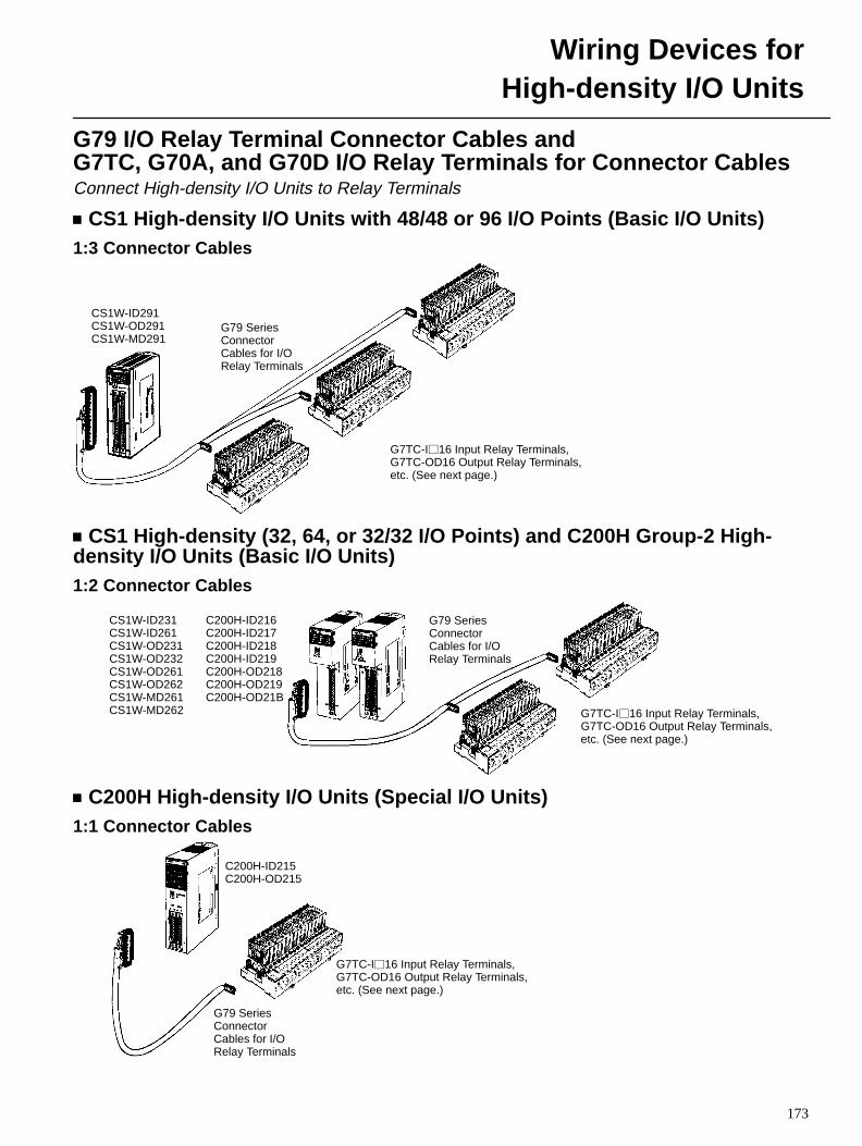
Wiring Devices forHigh-density I/O Units
173
G79 I/O Relay Terminal Connector Cables and G7TC, G70A, and G70D I/O Relay Terminals for Connector CablesConnect High-density I/O Units to Relay Terminals
CS1 High-density I/O Units with 48/48 or 96 I/O Points (Basic I/O Units)1:3 Connector Cables
CS1W-ID291CS1W-OD291CS1W-MD291
G7TC-I16 Input Relay Terminals,G7TC-OD16 Output Relay Terminals,etc. (See next page.)
G79 SeriesConnectorCables for I/ORelay Terminals
CS1 High-density (32, 64, or 32/32 I/O Points) and C200H Group-2 High-density I/O Units (Basic I/O Units)1:2 Connector Cables
C200H-ID216C200H-ID217C200H-ID218C200H-ID219C200H-OD218C200H-OD219C200H-OD21B
G7TC-I16 Input Relay Terminals,G7TC-OD16 Output Relay Terminals,etc. (See next page.)
G79 SeriesConnectorCables for I/ORelay Terminals
CS1W-ID231CS1W-ID261CS1W-OD231CS1W-OD232CS1W-OD261CS1W-OD262CS1W-MD261CS1W-MD262
C200H High-density I/O Units (Special I/O Units)1:1 Connector Cables
C200H-ID215C200H-OD215
G79 SeriesConnectorCables for I/ORelay Terminals
G7TC-I16 Input Relay Terminals,G7TC-OD16 Output Relay Terminals,etc. (See next page.)
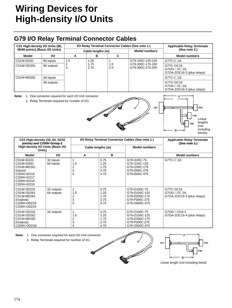
Wiring Devices forHigh-density I/O Units
174
G79 I/O Relay Terminal Connector CablesCS1 High-density I/O Units (96,48/48 i t ) (B i I/O U it )
I/O Relay Terminal Connector Cables (See note 1.) Applicable Relay T erminals(S t 2 )
CS g de s y /O U s (96,48/48 points) (Basic I/O Units) Cable lengths (m) Model numbers
pp cab e e ay e a s (See note 2.)
Model I/O A B C
ode u be s
Model numbers
CS1W-ID291 96 inputs 1.52
1.251 75
11 5
G79-150C-125-100G79 200C 175 150
G7TC-I16
CS1W-OD291 96 outputs
523
51.752.75
1.52.5
G 9 50C 5 00G79-200C-175-150G79-300C-275-250
G7TC-OC16G7OD-O16G7OA-ZOC16-3 (plus relays)
CS1W-MD291 48 inputs G7TC-I16CS 9
48 outputs G7TC-OC16G7OD-O16G7OA-ZOC16-3 (plus relays)
A
B
Note: 1. One connector required for each I/O Unit connector
2. Relay Terminals required for number of I/O.
Linearlengths(notincludingbends)
CS1 High-density (32, 64, 32/32points ) and C200H Grou p-2
I/O Relay Terminal Connector Cables (See note 1.) Applicable Relay T erminals (See note 2. )points) and C200H Group-2
High-density I/O Units (Basic I/OUnits)
Cable lengths (m) Model numbers (See note 2.)
Model I/O A B Model numbers
CS1W-ID231CS1W-ID261CS1W-MD261(inputs)C200H-ID216C200H-ID217C200H-ID218C200H-ID219
32 inputs64 inputs
11.5235
0.751.251.752.754.75
G79-I100C-75G79-I150C-125G79-I200C-175G79-I300C-275G79-I500C-475
G7TC-I16
CS1W-OD231CS1W-OD261CS1W-MD261(Outputs)C200H-OD218C200H-OD219
32 outputs64 outputs
11.5235
0.751.251.752.754.75
G79-O100C-75G79-O150C-125G79-O200C-175G79-P300C-275G79-O500C-475
G7TC-OC16G7OD-O16G7OA-ZOC16-3 (plus relays)
CS1W-OD232CS1W-OD262CS1W-MD262(Outputs)C200H-OD21B
32 outputs 11.5235
0.751.251.752.754.75
G79-O100C-75G79-O150C-125G79-O200C-175G79-P300C-275G79-O500C-475
G7OD-O16-1G7OA-ZOC16-4 (plus relays)
A
B
Note: 1. One connector required for each I/O Unit connector
2. Relay Terminals required for number of I/O.
Linear length (not including bend)
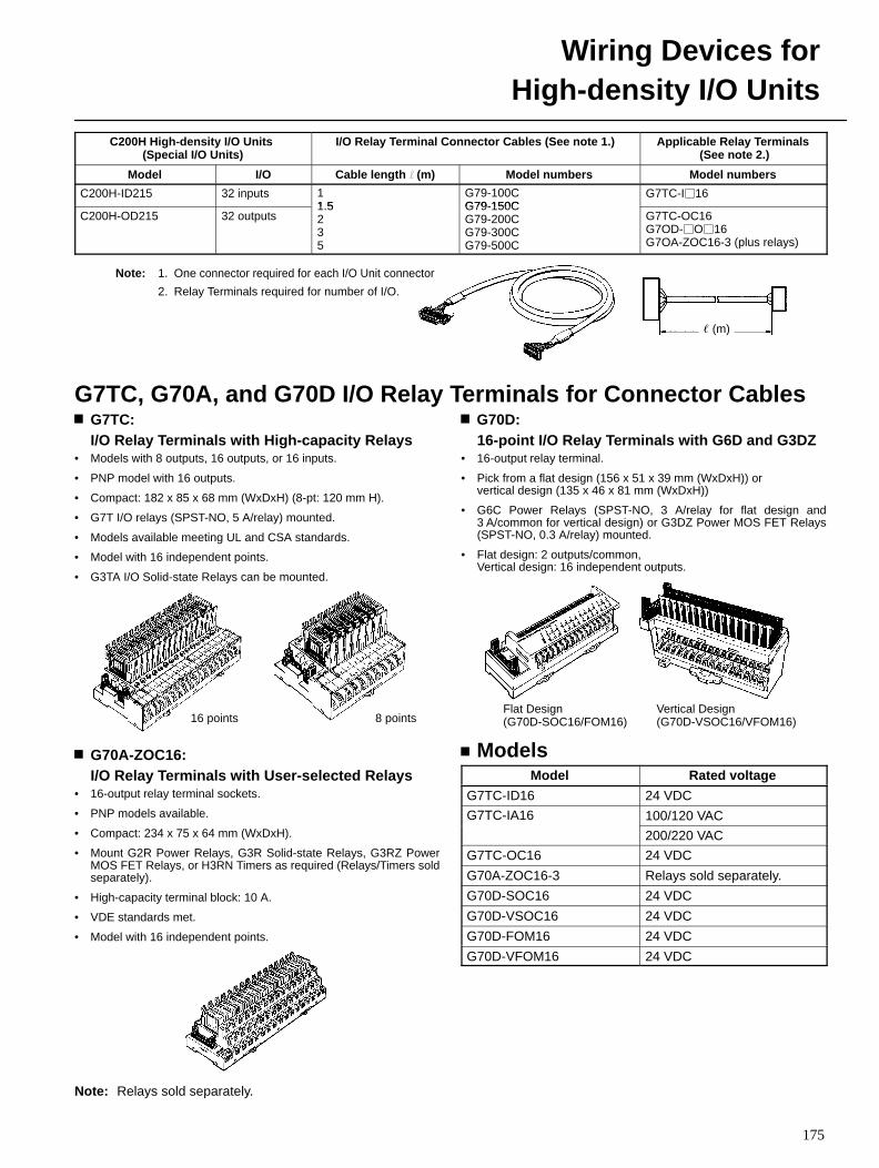
Wiring Devices forHigh-density I/O Units
175
C200H High-density I/O Units (Special I/O Units)
I/O Relay Terminal Connector Cables (See note 1.) Applicable Relay T erminals (See note 2.)
Model I/O Cable length l (m) Model numbers Model numbers
C200H-ID215 32 inputs 11 5
G79-100CG79-150C
G7TC-I16
C200H-OD215 32 outputs1.5235
G79-150CG79-200CG79-300CG79-500C
G7TC-OC16G7OD-O16G7OA-ZOC16-3 (plus relays)
(m)
Note: 1. One connector required for each I/O Unit connector
2. Relay Terminals required for number of I/O.
G7TC, G70A, and G70D I/O Relay Terminals for Connector CablesG7TC: I/O Relay Terminals with High-capacity Relays
• Models with 8 outputs, 16 outputs, or 16 inputs.
• PNP model with 16 outputs.
• Compact: 182 x 85 x 68 mm (WxDxH) (8-pt: 120 mm H).
• G7T I/O relays (SPST-NO, 5 A/relay) mounted.
• Models available meeting UL and CSA standards.
• Model with 16 independent points.
• G3TA I/O Solid-state Relays can be mounted.
16 points 8 points
G70A-ZOC16: I/O Relay Terminals with User-selected Relays
• 16-output relay terminal sockets.
• PNP models available.
• Compact: 234 x 75 x 64 mm (WxDxH).
• Mount G2R Power Relays, G3R Solid-state Relays, G3RZ PowerMOS FET Relays, or H3RN Timers as required (Relays/Timers soldseparately).
• High-capacity terminal block: 10 A.
• VDE standards met.
• Model with 16 independent points.
Note: Relays sold separately.
G70D: 16-point I/O Relay Terminals with G6D and G3DZ
• 16-output relay terminal.
• Pick from a flat design (156 x 51 x 39 mm (WxDxH)) or vertical design (135 x 46 x 81 mm (WxDxH))
• G6C Power Relays (SPST-NO, 3 A/relay for flat design and3 A/common for vertical design) or G3DZ Power MOS FET Relays(SPST-NO, 0.3 A/relay) mounted.
• Flat design: 2 outputs/common, Vertical design: 16 independent outputs.
Flat Design(G70D-SOC16/FOM16)
Vertical Design(G70D-VSOC16/VFOM16)
ModelsModel Rated voltage
G7TC-ID16 24 VDC
G7TC-IA16 100/120 VAC
200/220 VAC
G7TC-OC16 24 VDC
G70A-ZOC16-3 Relays sold separately.
G70D-SOC16 24 VDC
G70D-VSOC16 24 VDC
G70D-FOM16 24 VDC
G70D-VFOM16 24 VDC
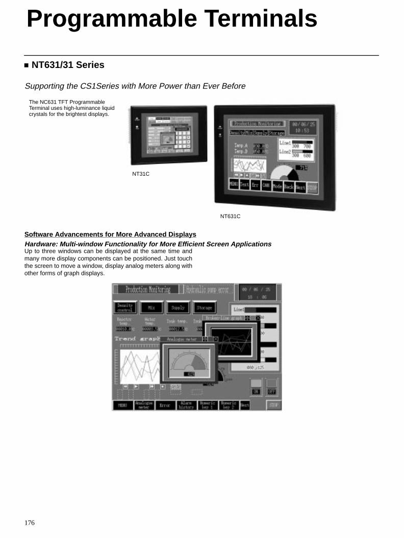
176
NT631/31 Series
Supporting the CS1Series with More Power than Ever Before
The NC631 TFT ProgrammableTerminal uses high-luminance liquidcrystals for the brightest displays.
NT31C
NT631C
Software Advancements for More Advanced DisplaysHardware: Multi-window Functionality for More Efficient Screen ApplicationsUp to three windows can be displayed at the same time andmany more display components can be positioned. Just touchthe screen to move a window, display analog meters along withother forms of graph displays.
Programmable Terminals
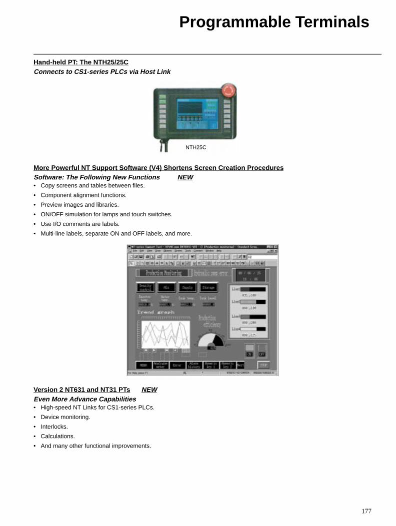
Programmable Terminals
177
Hand-held PT: The NTH25/25CConnects to CS1-series PLCs via Host Link
NTH25C
More Powerful NT Support Software (V4) Shortens Screen Creation ProceduresSoftware: The Following New Functions NEW• Copy screens and tables between files.
• Component alignment functions.
• Preview images and libraries.
• ON/OFF simulation for lamps and touch switches.
• Use I/O comments are labels.
• Multi-line labels, separate ON and OFF labels, and more.
Version 2 NT631 and NT31 PTs NEWEven More Advance Capabilities• High-speed NT Links for CS1-series PLCs.
• Device monitoring.
• Interlocks.
• Calculations.
• And many other functional improvements.
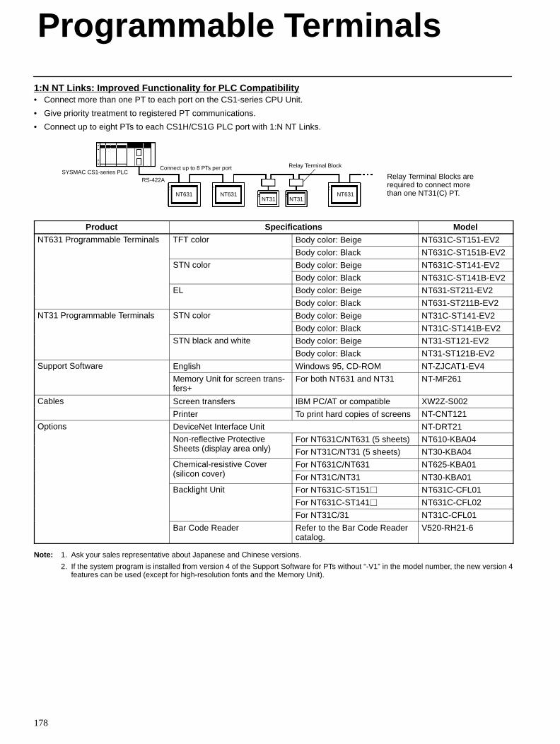
Programmable Terminals
178
1:N NT Links: Improved Functionality for PLC Compatibility• Connect more than one PT to each port on the CS1-series CPU Unit.
• Give priority treatment to registered PT communications.
• Connect up to eight PTs to each CS1H/CS1G PLC port with 1:N NT Links.
SYSMAC CS1-series PLCRS-422A
Connect up to 8 PTs per port Relay Terminal Block
Relay Terminal Blocks arerequired to connect morethan one NT31(C) PT.NT631 NT631 NT631
NT31 NT31
Product Specifications Model
NT631 Programmable Terminals TFT color Body color: Beige NT631C-ST151-EV2g
Body color: Black NT631C-ST151B-EV2
STN color Body color: Beige NT631C-ST141-EV2
Body color: Black NT631C-ST141B-EV2
EL Body color: Beige NT631-ST211-EV2
Body color: Black NT631-ST211B-EV2
NT31 Programmable Terminals STN color Body color: Beige NT31C-ST141-EV2g
Body color: Black NT31C-ST141B-EV2
STN black and white Body color: Beige NT31-ST121-EV2
Body color: Black NT31-ST121B-EV2
Support Software English Windows 95, CD-ROM NT-ZJCAT1-EV4
Memory Unit for screen trans-fers+
For both NT631 and NT31 NT-MF261
Cables Screen transfers IBM PC/AT or compatible XW2Z-S002
Printer To print hard copies of screens NT-CNT121
Options DeviceNet Interface Unit NT-DRT21
Non-reflective ProtectiveSh (di l l )
For NT631C/NT631 (5 sheets) NT610-KBA04Sheets (display area only) For NT31C/NT31 (5 sheets) NT30-KBA04
Chemical-resistive Cover ( ili )
For NT631C/NT631 NT625-KBA01(silicon cover) For NT31C/NT31 NT30-KBA01
Backlight Unit For NT631C-ST151 NT631C-CFL01g
For NT631C-ST141 NT631C-CFL02
For NT31C/31 NT31C-CFL01
Bar Code Reader Refer to the Bar Code Readercatalog.
V520-RH21-6
Note: 1. Ask your sales representative about Japanese and Chinese versions.
2. If the system program is installed from version 4 of the Support Software for PTs without “-V1” in the model number, the new version 4features can be used (except for high-resolution fonts and the Memory Unit).
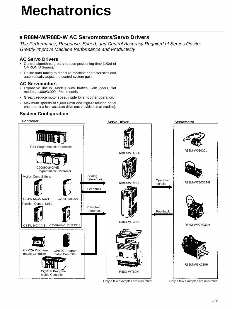
179
R88M-W/R88D-W AC Servomotors/Servo DriversThe Performance, Response, Speed, and Control Accuracy Required of Servos Onsite: Greatly Improve Machine Performance and Productivity
AC Servo Drivers• Control algorithms greatly reduce positioning time (1/3rd of
OMRON U Series).
• Online auto-tuning to measure machine characteristics andautomatically adjust the control system gain.
AC Servomotors• Expansive lineup: Models with brakes, with gears, flat
models, 1,000/3,000–r/min models.
• Greatly reduce motor speed ripple for smoother operation.
• Maximum speeds of 5,000 r/min and high-resolution serialencoder for a fast, accurate drive (not provided on all models).
System Configuration
CS1W-MC221/421 C200H-MC221
CS1W-NC3 C200HW-NC113/213/413
R88D-WTA3HL
R88D-WT08H
R88D-WT60H
R88D-WT30H
R88M-W03030L
R88M-W75030T-B
R88M-WP75030H
R88M-W3K030H
Controller Servo Driver Servomotor
CS1 Programmable Controller
C200HX/HG/HE Programmable Controller
Motion Control Units
Position Control Units
CPM2A Program-mable Controller
CPM2C Program-mable Controller
CQM1H Program-mable Controller
Analogreferences
Feedback
Pulse trainreferences
Operationsignals
Feedback
Only a few examples are illustrated. Only a few examples are illustrated.
Mechatronics
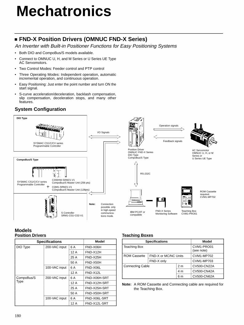
Mechatronics
180
FND-X Position Drivers (OMNUC FND-X Series)An Inverter with Built-in Positioner Functions for Easy Positioning Systems• Both DIO and CompoBus/S models available.
• Connect to OMNUC U, H, and M Series or U Series UE TypeAC Servomotors.
• Two Control Modes: Feeder control and PTP control
• Three Operating Modes: Independent operation, automaticincremental operation, and continuous operation.
• Easy Positioning: Just enter the point number and turn ON thestart signal.
• S-curve acceleration/deceleration, backlash compensation,slip compensation, deceleration stops, and many otherfeatures.
System Configuration
DIO Type
I/O Signals
CompoBus/S Type
Position DriverOMNUC FND-X SeriesDIO TypeCompoBus/S Type
IBM PC/AT orcompatible
AC ServomotorOMNUC U, H, or MSeries or U Series UE Type
FND-X SeriesMonitoring Software
Teaching BoxCVM1-PRO01
ROM Cassetterequired.CVM1-MP702
SYSMAC CS1/C/CV seriesProgrammable Controller
SYSMAC CS1/C/CV seriesProgrammable Controller
S ControllerSRM1-C01/-C02-V1
Feedback signals
Operation signals
RS-232C
C200HW-SRM21-V1CompoBus/S Master Unit (256 pts)
CQM1-SRM21-V1CompoBus/S Master Unit (128pts)
Note: Connectionpossible onlyin high-speedcommunica-tions mode.
ModelsPosition Drivers
Specifications Model
DIO Type 200-VAC input 6 A FND-X06HO y e 00 C u
12 A FND-X12H
25 A FND-X25H
50 A FND-X50H
100-VAC input 6 A FND-X06L00 C u
12 A FND-X12L
CompoBus/ST
200-VAC input 6 A FND-X06H-SRTCo o us/SType
00 C u
12 A FND-X12H-SRT
25 A FND-X25H-SRT
50 A FND-X50H-SRT
100-VAC input 6 A FND-X06L-SRT00 C u
12 A FND-X12L-SRT
Teaching BoxesSpecifications Model
Teaching Box CVM1-PRO01 (see note)
ROM Cassette FND-X or MC/NC Units CVM1-MP702O Casse e
FND-X only CVM1-MP703
Connecting Cable 2 m CV500-CN22ACo ec g Cab e
4 m CV500-CN42A
6 m CV500-CN62A
Note: A ROM Cassette and Connecting cable are required forthe Teaching Box.
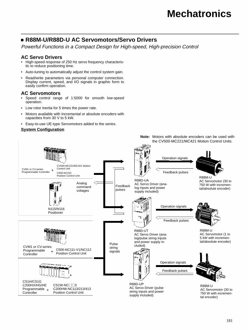
Mechatronics
181
R88M-U/R88D-U AC Servomotors/Servo DriversPowerful Functions in a Compact Design for High-speed, High-precision Control
AC Servo Drivers• High-speed response of 250 Hz servo frequency characteris-
tic to reduce positioning time.
• Auto-tuning to automatically adjust the control system gain.
• Read/write parameters via personal computer connection.Display current, speed, and I/O signals in graphic form toeasily confirm operation.
AC Servomotors• Speed control range of 1:5000 for smooth low-speed
operation.
• Low rotor inertia for 5 times the power rate.
• Motors available with Incremental or absolute encoders withcapacities from 30 V to 5 kW.
• Easy-to-use UE-type Servomotors added to the series.
System Configuration
CVM1 or CV-seriesProgrammable Controller
CV500-MC221/MC421 MotionControl Unit
C500-NC222Position Control Unit
N115/N116Positioner
CVM1 or CV-seriesProgrammableController
C500-NC111-V1/NC112Position Control Unit
CS1H/CS1GC200HX/HG/HEProgrammableController
CS1W-NC3C200HW-NC113/213/413Position Control Unit
Analogcommandvoltages
Feedbackpulses
R88D-UA AC Servo Driver (ana-log inputs and powersupply included)
Operation signals
Feedback pulses
R88M-UAC Servomotor (30 to750 W with incremen-tal/absolute encoder)
Pulsestringsignals
Note: Motors with absolute encoders can be used withthe CV500-MC221/MC421 Motion Control Units.
R88D-UT AC Servo Driver (ana-log/pulse string inputsand power supply in-cluded)
Operation signals
Feedback pulses
R88M-UAC Servomotor (1 to5 kW with incremen-tal/absolute encoder)
R88D-UP AC Servo Driver (pulsestring inputs and powersupply included)
Operation signals
Feedback pulses
R88M-UAC Servomotor (30 to750 W with incremen-tal encoder)
+
+
+
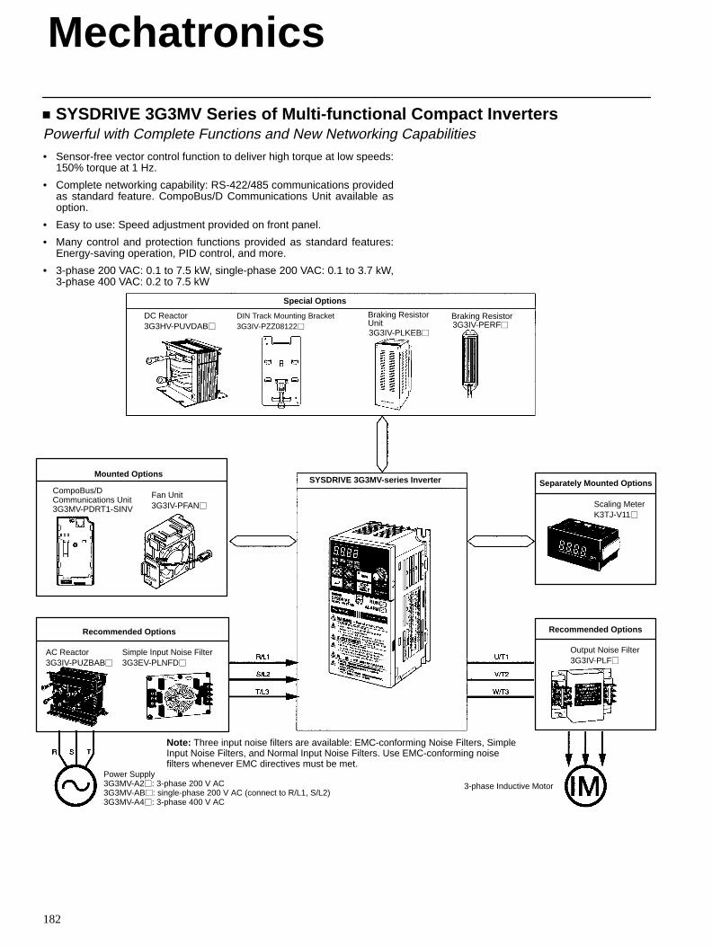
Mechatronics
182
SYSDRIVE 3G3MV Series of Multi-functional Compact InvertersPowerful with Complete Functions and New Networking Capabilities
• Sensor-free vector control function to deliver high torque at low speeds:150% torque at 1 Hz.
• Complete networking capability: RS-422/485 communications providedas standard feature. CompoBus/D Communications Unit available asoption.
• Easy to use: Speed adjustment provided on front panel.
• Many control and protection functions provided as standard features:Energy-saving operation, PID control, and more.
• 3-phase 200 VAC: 0.1 to 7.5 kW, single-phase 200 VAC: 0.1 to 3.7 kW,3-phase 400 VAC: 0.2 to 7.5 kW
DC Reactor3G3HV-PUVDAB
DIN Track Mounting Bracket3G3IV-PZZ08122
Braking Resistor
Special Options
Simple Input Noise Filter3G3EV-PLNFD
Scaling MeterK3TJ-V11
Separately Mounted Options
Recommended Options
Output Noise Filter3G3IV-PLF
Mounted Options
CompoBus/DCommunications Unit3G3MV-PDRT1-SINV
Fan Unit3G3IV-PFAN
Recommended Options
AC Reactor3G3IV-PUZBAB
SYSDRIVE 3G3MV-series Inverter
Braking ResistorUnit
Power Supply3G3MV-A2: 3-phase 200 V AC3G3MV-AB: single-phase 200 V AC (connect to R/L1, S/L2)3G3MV-A4: 3-phase 400 V AC
3-phase Inductive Motor
Note: Three input noise filters are available: EMC-conforming Noise Filters, SimpleInput Noise Filters, and Normal Input Noise Filters. Use EMC-conforming noisefilters whenever EMC directives must be met.
3G3IV-PLKEB3G3IV-PERF
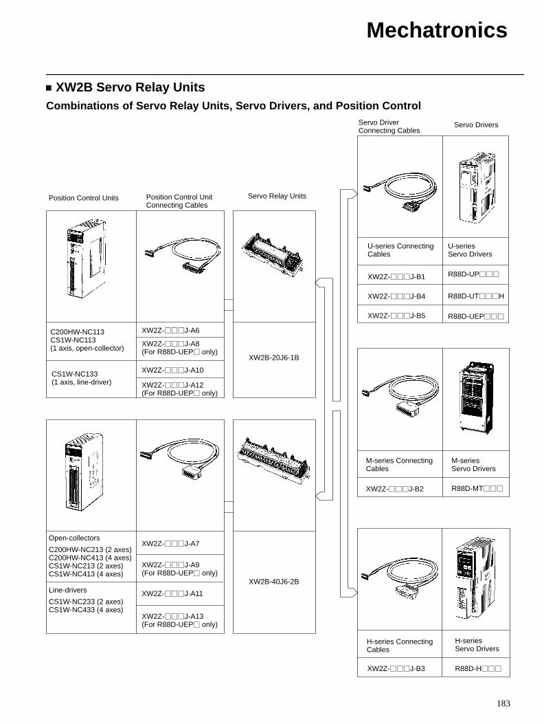
Mechatronics
183
XW2B Servo Relay UnitsCombinations of Servo Relay Units, Servo Drivers, and Position Control
Servo DriverConnecting Cables
Servo Drivers
U-series ConnectingCables
U-series Servo Drivers
XW2Z-J-B1 R88D-UP
M-series ConnectingCables
Position Control Units Position Control UnitConnecting Cables
Servo Relay Units
XW2B-20J6-1B
C200HW-NC113CS1W-NC113 (1 axis, open-collector)
CS1W-NC133(1 axis, line-driver)
XW2Z-J-A7
XW2Z-J-A9(For R88D-UEP only)
XW2Z-J-A11
XW2Z-J-A6
XW2Z-J-A8(For R88D-UEP only)
XW2Z-J-A12 (For R88D-UEP only)
XW2B-40J6-2B
XW2Z-J-B4
XW2Z-J-B5
XW2Z-J-B2
XW2Z-J-B3
R88D-UTH
R88D-UEP
R88D-MT
R88D-H
M-series Servo Drivers
H-series ConnectingCables
H-series Servo Drivers
XW2Z-J-A13 (For R88D-UEP only)
XW2Z-J-A10
Open-collectors
C200HW-NC213 (2 axes)C200HW-NC413 (4 axes)CS1W-NC213 (2 axes)CS1W-NC413 (4 axes)
Line-drivers
CS1W-NC233 (2 axes)CS1W-NC433 (4 axes)