Embed Size (px)
Citation preview
INITIAL TYPE TEST RESULT OF CLASS 1 E GAS TURBINE GENERATOR SYSTEM MUAP-10023-NP(RO)
Initial Type Test Result of Class 1 E Gas Turbine Generator System
Non Proprietary Version
December 2010
©2010 Mitsubishi Heavy Industries, Ltd. All Rights Reserved
Mitsubishi Heavy Industries, LTD.
INITIAL TYPE TEST RESULT OF CLASS 1E GAS TURBINE GENERATOR SYSTEM MUAP-10023-NP(R0)
Mitsubishi Heavy Industries, LTD.
Revision History
Revision Page Description
0 All Original issued
INITIAL TYPE TEST RESULT OF CLASS 1E GAS TURBINE GENERATOR SYSTEM MUAP-10023-NP(R0)
Mitsubishi Heavy Industries, LTD.
© 2010 MITSUBISHI HEAVY INDUSTRIES, LTD.
All Rights Reserved This document has been prepared by Mitsubishi Heavy Industries, Ltd. (“MHI”) in connection with the U.S. Nuclear Regulatory Commission (“NRC”) licensing review of MHI’s US-APWR nuclear power plant design. No right to disclose, use or copy any of the information in this document, other that by the NRC and its contractors in support of the licensing review of the US-APWR, is authorized without the express written permission of MHI. This document contains technology information and intellectual property relating to the US-APWR and it is delivered to the NRC on the express condition that it not be disclosed, copied or reproduced in whole or in part, or used for the benefit of anyone other than MHI without the express written permission of MHI, except as set forth in the previous paragraph. This document is protected by the laws of Japan, U.S. copyright law, international treaties and conventions, and the applicable laws of any country where it is being used.
Mitsubishi Heavy Industries, Ltd. 16-5, Konan 2-chome, Minato-ku
Tokyo 108-8215 Japan
INITIAL TYPE TEST RESULT OF CLASS 1E GAS TURBINE GENERATOR SYSTEM MUAP-10023-NP(R0)
Mitsubishi Heavy Industries, LTD.
Abstract
This technical report describes the summary of result of initial type test of Class 1E Gas Turbine Generator (GTG) unit of US-APWR. MHI have performed initial type test required in IEEE 387-1995 as part of Class 1E qualification program of Class 1E GTG units of US-APWR. This report notices that GTG passed the initial type test required and verified the availability to apply for Class 1E emergency power units. This technical report describes the followings Scope of qualification Specification of components tested Procedures, acceptance criteria and test conditions of tests Summary of result Consideration
INITIAL TYPE TEST RESULT OF CLASS 1E GAS TURBINE GENERATOR SYSTEM MUAP-10023-NP(R0)
Mitsubishi Heavy Industries, LTD. i
Table of Contents
List of Tables ························································································································· iii List of Figures ·······················································································································iv List of Acronyms ····················································································································v
1.0 INTRODUCTION/OVERVIEW ................................................................................ 1-1
2.0 LIST OF STANDARDS AND REGULATIONS ......................................................... 2-1
2.1 NRC Documents ............................................................................................ 2-1 2.2 Industry Standards – IEEE ............................................................................. 2-1 2.3 Other Industry Standards ............................................................................... 2-2
3.0 DEFINITIONS............................................................................................................ 3-1
4.0 SCOPE......................................................................................................................4-1
4.1 General……………………………………………………………………………..…4-1 4.2 Prototype System Tested……………………………………………………………4-2
5.0 PROTOTYPE SYSTEM ............................................................................................ 5-1
5.1 General........................................................................................................... 5-1 5.2 System specification....................................................................................... 5-1 5.3 Component Specification ............................................................................... 5-3
6.0 INITIAL TYPE TEST ................................................................................................. 6-1
6.1 General........................................................................................................... 6-1 6.2 Load Capability Test....................................................................................... 6-1 6.3 Start And Load Acceptance Tests.................................................................. 6-3 6.4 Margin Tests................................................................................................... 6-5 6.5 Load Transient Tests...................................................................................... 6-6
7.0 CONSIDERATION .................................................................................................... 7-1
8.0 CONCLUSIONS........................................................................................................ 8-1
9.0 REFERENCES.......................................................................................................... 9-1
Appendix A US-APWR Typical Load Profiles ............................................................ A-1
Appendix B GTG Technical Specification.................................................................. B-1
INITIAL TYPE TEST RESULT OF CLASS 1E GAS TURBINE GENERATOR SYSTEM MUAP-10023-NP(R0)
Mitsubishi Heavy Industries, LTD. ii
Appendix C Parameter Chart ...................................................................................... C-1
Appendix D Initial Type Test Procedure .................................................................... D-1
INITIAL TYPE TEST RESULT OF CLASS 1E GAS TURBINE GENERATOR SYSTEM MUAP-10023-NP(R0)
Mitsubishi Heavy Industries, LTD. iii
List of Tables
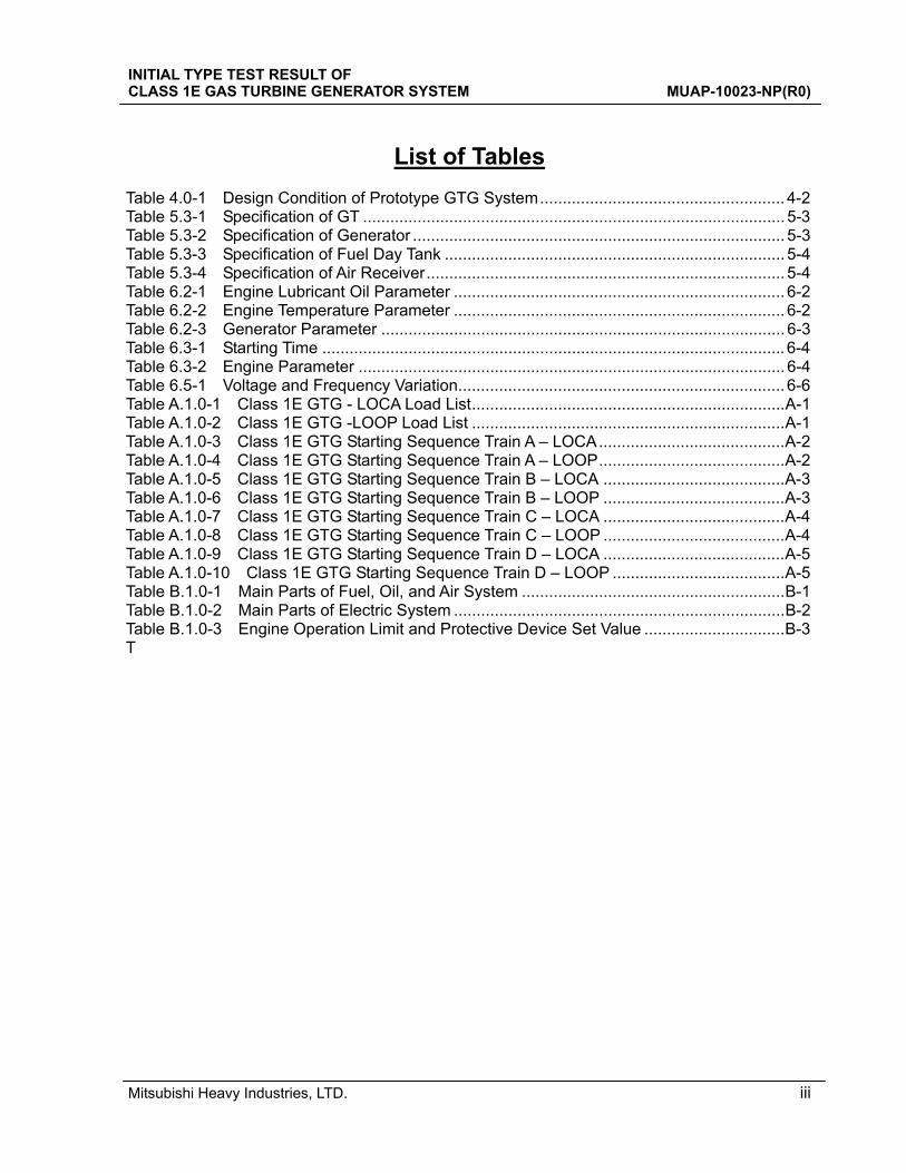
Table 4.0-1 Design Condition of Prototype GTG System...................................................... 4-2 Table 5.3-1 Specification of GT ............................................................................................. 5-3 Table 5.3-2 Specification of Generator .................................................................................. 5-3 Table 5.3-3 Specification of Fuel Day Tank ........................................................................... 5-4 Table 5.3-4 Specification of Air Receiver............................................................................... 5-4 Table 6.2-1 Engine Lubricant Oil Parameter ......................................................................... 6-2 Table 6.2-2 Engine Temperature Parameter ......................................................................... 6-2 Table 6.2-3 Generator Parameter ......................................................................................... 6-3 Table 6.3-1 Starting Time ...................................................................................................... 6-4 Table 6.3-2 Engine Parameter .............................................................................................. 6-4 Table 6.5-1 Voltage and Frequency Variation........................................................................ 6-6 Table A.1.0-1 Class 1E GTG - LOCA Load List.....................................................................A-1 Table A.1.0-2 Class 1E GTG -LOOP Load List .....................................................................A-1 Table A.1.0-3 Class 1E GTG Starting Sequence Train A – LOCA.........................................A-2 Table A.1.0-4 Class 1E GTG Starting Sequence Train A – LOOP.........................................A-2 Table A.1.0-5 Class 1E GTG Starting Sequence Train B – LOCA ........................................A-3 Table A.1.0-6 Class 1E GTG Starting Sequence Train B – LOOP ........................................A-3 Table A.1.0-7 Class 1E GTG Starting Sequence Train C – LOCA ........................................A-4 Table A.1.0-8 Class 1E GTG Starting Sequence Train C – LOOP ........................................A-4 Table A.1.0-9 Class 1E GTG Starting Sequence Train D – LOCA ........................................A-5 Table A.1.0-10 Class 1E GTG Starting Sequence Train D – LOOP ......................................A-5 Table B.1.0-1 Main Parts of Fuel, Oil, and Air System ..........................................................B-1 Table B.1.0-2 Main Parts of Electric System .........................................................................B-2 Table B.1.0-3 Engine Operation Limit and Protective Device Set Value ...............................B-3 T
INITIAL TYPE TEST RESULT OF CLASS 1E GAS TURBINE GENERATOR SYSTEM MUAP-10023-NP(R0)
Mitsubishi Heavy Industries, LTD. iv
List of Figures
Figure 4.0-1 Scope Diagram................................................................................................. 4-1 Figure A.1.0-1 LOCA Condition Class 1E GTG Load Profile (Train A) .................................A-6 Figure A.1.0-2 LOOP Condition Class 1E GTG Load Profile (Train A) .................................A-7 Figure A.1.0-3 LOCA Condition Class 1E GTG Load Profile (Train B) .................................A-8 Figure A.1.0-4 LOOP Condition Class 1E GTG Load Profile (Train B).................................A-9 Figure A.1.0-5 LOCA Condition Class 1E GTG Load Profile (Train C) ...............................A-10 Figure A.1.0-6 LOOP Condition Class 1E GTG Load Profile (Train C)...............................A-11 Figure A.1.0-7 LOCA Condition Class 1E GTG Load Profile (Train D) ...............................A-12 Figure A.1.0-8 LOOP Condition Class 1E GTG Load Profile (Train D)...............................A-13 Figure B.1.0-1 Cross Sectional View of Power Section........................................................B-4 Figure B.1.0-2 Gear Train of Reduction Gear Box................................................................B-5 Figure B.1.0-3 Installation Drawing of Gas Turbine Assembly..............................................B-6 Figure B.1.0-4 Drawing of Fuel Day Tank...........................................................................B-12 Figure B.1.0-5 Drawing of Air Reciever ..............................................................................B-14 Figure B.1.0-6 Drawing of Enclosure and Skid...................................................................B-17 Figure B.1.0-7 Configuration of Lubricant Oil System ........................................................B-20 Figure B.1.0-8 Configuration of Fuel Oil System ................................................................B-22 Figure B.1.0-9 Configuration of Starting Air System ...........................................................B-23 Figure B.1.0-10 Drawing of Inlet Air / Exhaust System.......................................................B-25 Figure B.1.0-11 Drawing of Generator Circuit.....................................................................B-26 Figure B.1.0-12 Drawing of Alarm Panel ............................................................................B-27 Figure C.1.0-1 Parameter Chart of Load Capability Test..................................................... C-1 Figure C.1.0-2 Parameter Chart of Start and Load Acceptance Test, No.77, Cold.............. C-2 Figure C.1.0-3 Parameter Chart of Start and Load Acceptance Test, No.78, Hot................ C-3 Figure C.1.0-4 Parameter Chart of Start and Load Acceptance Test, No.79, Hot................ C-4 Figure C.1.0-5 Parameter Chart of Start and Load Acceptance Test, No.80, Hold.............. C-5 Figure C.1.0-6 Parameter Chart of Start and Load Acceptance Test, No.81, Hot................ C-6 Figure C.1.0-7 Parameter Chart of No.1 Margin Test .......................................................... C-7 Figure C.1.0-8 Parameter Chart of No.2 Margin Test .......................................................... C-8 Figure C.1.0-9 Parameter Chart of Load Transient Test, 25%............................................. C-9 Figure C.1.0-10 Parameter Chart of Load Transient Test, 50%......................................... C-10 Figure C.1.0-11 Parameter Chart of Load Transient Test, 75%......................................... C-12 Figure C.1.0-12 Parameter Chart of Load Transient Test, 100%....................................... C-14
INITIAL TYPE TEST RESULT OF CLASS 1E GAS TURBINE GENERATOR SYSTEM MUAP-10023-NP(R0)
Mitsubishi Heavy Industries, LTD. v
List of Acronyms
ac Alternate Current dc Direct Current CDP Compressor Discharge Pressure CPS Control Protection and Surveillance systems CPU Central Processing Unit CT Current Transformer DG Diesel Generator ECCS Emergency Core Cooling System EGT Exhaust Gas Temperature ESI Engine System Inc. ESFAS Engineered Safety Features Actuation System FMEA Failure Modes and Effects Analysis FOA Fuel, Oil and Air GTG Gas Turbine Generator I&C Instrumentation and Control I/O Input/Output IV&V Independent Verification and Validation KHI Kawasaki Heavy Industries LOCA Loss of Coolant Accident LOOP Loss of Offsite Power MCR Main Control Room MHI Mitsubishi Heavy Industries MTBF Mean Time Between Failure QA Quality Assurance RTD Resistance Temperature Detector SLS Safety Logic System UV Under Voltage VDU Visual Display System VT Voltage Transformer
INITIAL TYPE TEST RESULT OF CLASS 1E GAS TURBINE GENERATOR SYSTEM MUAP-10023-NP(R0)
Mitsubishi Heavy Industries, LTD. 1-1
1.0 INTRODUCTION/OVERVIEW
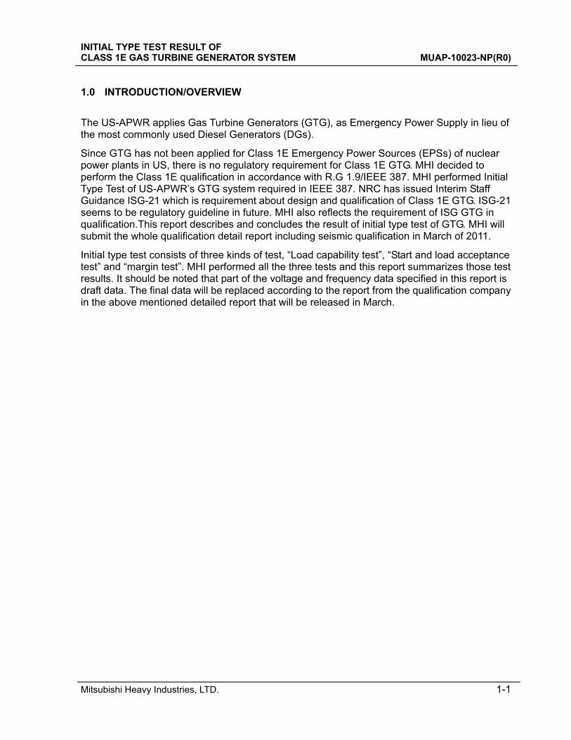
The US-APWR applies Gas Turbine Generators (GTG), as Emergency Power Supply in lieu of the most commonly used Diesel Generators (DGs).
Since GTG has not been applied for Class 1E Emergency Power Sources (EPSs) of nuclear power plants in US, there is no regulatory requirement for Class 1E GTG. MHI decided to perform the Class 1E qualification in accordance with R.G 1.9/IEEE 387. MHI performed Initial Type Test of US-APWR’s GTG system required in IEEE 387. NRC has issued Interim Staff Guidance ISG-21 which is requirement about design and qualification of Class 1E GTG. ISG-21 seems to be regulatory guideline in future. MHI also reflects the requirement of ISG GTG in qualification.This report describes and concludes the result of initial type test of GTG. MHI will submit the whole qualification detail report including seismic qualification in March of 2011.
Initial type test consists of three kinds of test, “Load capability test”, “Start and load acceptance test” and “margin test”. MHI performed all the three tests and this report summarizes those test results. It should be noted that part of the voltage and frequency data specified in this report is draft data. The final data will be replaced according to the report from the qualification company in the above mentioned detailed report that will be released in March.
INITIAL TYPE TEST RESULT OF CLASS 1E GAS TURBINE GENERATOR SYSTEM MUAP-10023-NP(R0)
Mitsubishi Heavy Industries, LTD. 2-1
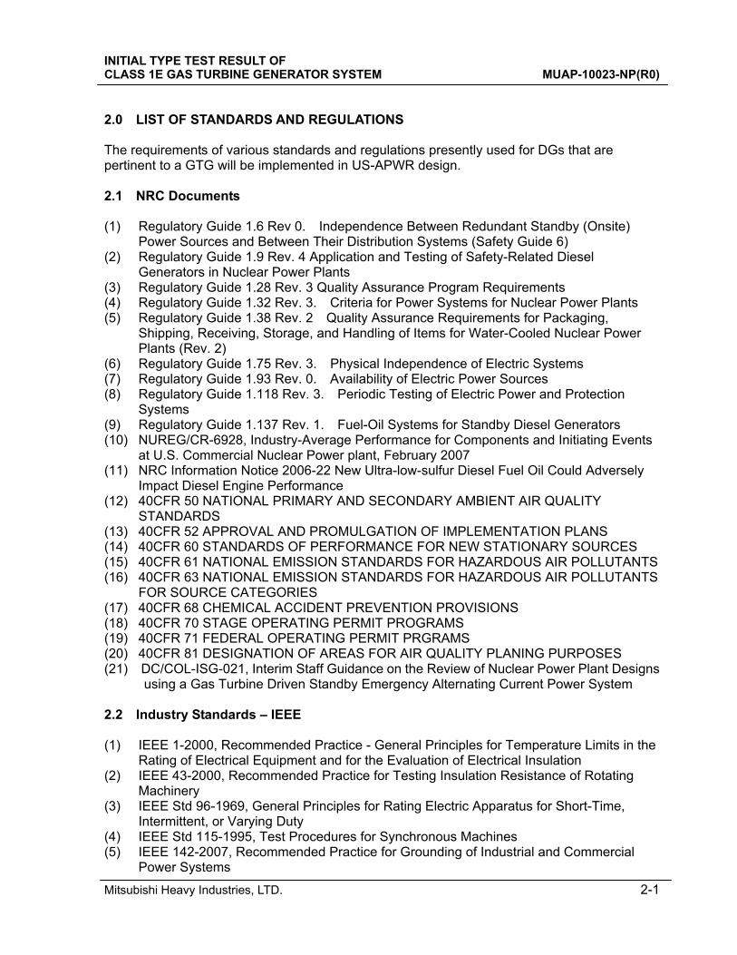
2.0 LIST OF STANDARDS AND REGULATIONS The requirements of various standards and regulations presently used for DGs that are pertinent to a GTG will be implemented in US-APWR design. 2.1 NRC Documents (1) Regulatory Guide 1.6 Rev 0. Independence Between Redundant Standby (Onsite)
Power Sources and Between Their Distribution Systems (Safety Guide 6) (2) Regulatory Guide 1.9 Rev. 4 Application and Testing of Safety-Related Diesel
Generators in Nuclear Power Plants (3) Regulatory Guide 1.28 Rev. 3 Quality Assurance Program Requirements (4) Regulatory Guide 1.32 Rev. 3. Criteria for Power Systems for Nuclear Power Plants (5) Regulatory Guide 1.38 Rev. 2 Quality Assurance Requirements for Packaging,
Shipping, Receiving, Storage, and Handling of Items for Water-Cooled Nuclear Power Plants (Rev. 2)
(6) Regulatory Guide 1.75 Rev. 3. Physical Independence of Electric Systems (7) Regulatory Guide 1.93 Rev. 0. Availability of Electric Power Sources (8) Regulatory Guide 1.118 Rev. 3. Periodic Testing of Electric Power and Protection
Systems (9) Regulatory Guide 1.137 Rev. 1. Fuel-Oil Systems for Standby Diesel Generators (10) NUREG/CR-6928, Industry-Average Performance for Components and Initiating Events
at U.S. Commercial Nuclear Power plant, February 2007 (11) NRC Information Notice 2006-22 New Ultra-low-sulfur Diesel Fuel Oil Could Adversely
Impact Diesel Engine Performance (12) 40CFR 50 NATIONAL PRIMARY AND SECONDARY AMBIENT AIR QUALITY
STANDARDS (13) 40CFR 52 APPROVAL AND PROMULGATION OF IMPLEMENTATION PLANS (14) 40CFR 60 STANDARDS OF PERFORMANCE FOR NEW STATIONARY SOURCES (15) 40CFR 61 NATIONAL EMISSION STANDARDS FOR HAZARDOUS AIR POLLUTANTS (16) 40CFR 63 NATIONAL EMISSION STANDARDS FOR HAZARDOUS AIR POLLUTANTS
FOR SOURCE CATEGORIES (17) 40CFR 68 CHEMICAL ACCIDENT PREVENTION PROVISIONS (18) 40CFR 70 STAGE OPERATING PERMIT PROGRAMS (19) 40CFR 71 FEDERAL OPERATING PERMIT PRGRAMS (20) 40CFR 81 DESIGNATION OF AREAS FOR AIR QUALITY PLANING PURPOSES (21) DC/COL-ISG-021, Interim Staff Guidance on the Review of Nuclear Power Plant Designs
using a Gas Turbine Driven Standby Emergency Alternating Current Power System 2.2 Industry Standards – IEEE (1) IEEE 1-2000, Recommended Practice - General Principles for Temperature Limits in the
Rating of Electrical Equipment and for the Evaluation of Electrical Insulation (2) IEEE 43-2000, Recommended Practice for Testing Insulation Resistance of Rotating
Machinery (3) IEEE Std 96-1969, General Principles for Rating Electric Apparatus for Short-Time,
Intermittent, or Varying Duty (4) IEEE Std 115-1995, Test Procedures for Synchronous Machines (5) IEEE 142-2007, Recommended Practice for Grounding of Industrial and Commercial
Power Systems
INITIAL TYPE TEST RESULT OF CLASS 1E GAS TURBINE GENERATOR SYSTEM MUAP-10023-NP(R0)
Mitsubishi Heavy Industries, LTD. 2-2
(6) IEEE 275-1992, Recommended Practice for Thermal Evaluation of Insulation Systems for Alternating-Current Electric Machinery Employing Form-Wound Preinsulated Stator Coils for Machines Rated 6900 V and Below
(7) IEEE Std 308-2001 - IEEE Standard Criteria for Class 1E Power Systems for Nuclear Power Generating Stations
(8) IEEE Std 323-2003 - IEEE Standard for Qualifying Class 1E Equipment for Nuclear Power Generating Stations
(9) IEEE 336-2005 IEEE Guide for Installation, Inspection, and Testing for Class 1E Power, Instrumentation, and Control Equipment at Nuclear Facilities
(10) IEEE 338-2006 – IEEE Standard Criteria for the Periodic Surveillance Testing of Nuclear Power Generating Station Safety Systems
(11) IEEE-344-2004 IEEE Recommended Practice for Seismic Qualification of Class 1E Equipment for Nuclear Power Generating Stations
(12) IEEE-379-2000 IEEE Standard Application of the Single Failure Criterion to Nuclear Power Generating Stations Safety Systems
(13) IEEE Std 384-2008 IEEE Standard Criteria for Independence of Class 1E Equipment and Circuits
(14) IEEE Std 387-1995 - IEEE Standard Criteria for Diesel Generator Units Applied as Standby Power Supply for Nuclear Power Generating Stations.
(15) IEEE-415-1986 IEEE Guide for Planning of Preoperational Testing Programs for Class 1E Power Systems for Nuclear Power Generating Stations.
(16) IEEE-421.3-1997 IEEE Standard for High Potential Test Requirements for Excitation Systems for Synchronous Machines
(17) IEEE-421.4-2004 IEEE Guide for the Preparation of Excitation System Specifications (18) IEEE 429-1994, Recommended Practice for Thermal Evaluation of Sealed Insulation
Systems for AC Electric Machinery Employing Form-Wound Preinsulated Stator Coils for Machines Rated 6900 V and Below
(19) IEEE-493-2007, Recommended Practice for the Design of Reliable Industrial and Commercial Power System
(20) IEEE Std 500-1984 IEEE Guide to the Collection and Presentation of Electrical, Electronic, Sensing Component, and Mechanical Equipment Reliability Data for Nuclear-Power Generating Stations
(21) IEEE-603-1998, IEEE Standard Criteria for Safety Systems for Nuclear Power Generating Stations
(22) IEEE-627-1980, IEEE Standard Criteria for Design Qualification of Safety Equipment Used in Nuclear Power Generating Stations
2.3 Other Industry Standards (1) NEMA FU-1-2002 Low Voltage Cartridge Fuses (2) NEMA MG-1-2006 Motors and Generators (3) ANSI/ASME NQA-1-2008 Quality Assurance Requirements for Nuclear Facility
Applicants (4) ANSI B31.1-2007 Power Piping (5) ANSI B37.20 Switchgear Assemblies including Metal Enclosed Bus (6) ANSI C37-90.1-2002 IEEE Standard for Surge Withstand Capabilities (SWC) Tests foor
Relays and Relay Systems Associated with Electric Power Apparatus (7) ANSI C37-101-2006 IEEE Guide for Generator Ground Protection (8) ANSI C37.102-2006 IEEE Guide for AC Generator Protection (9) ANSI C50.13-2005 IEEE Standard for Cylindrical-Rotor 50 Hz and 60 Hz Synchronous
Generators Rated 10 MVA and Above
INITIAL TYPE TEST RESULT OF CLASS 1E GAS TURBINE GENERATOR SYSTEM MUAP-10023-NP(R0)
Mitsubishi Heavy Industries, LTD. 2-3
(10) ANSI C50.14-1977 American National Standard Requirements for Combustion Gas Turbine Driven Cylindrical Rotor Synchronous Generators
(11) ANSI C57.13-1993 IEEE Standard Requirements for Instrument Transformers (if needed) (12) ANSI C62.92.2-1989 IEEE Guide for the Application Guide for Neutral Grounding in
Electrical Utility Systems, Pt II - Grounding of Synchronous Generator Systems. (13) ANSI/ASME B16.11-2009, Forged Fittings, Socket Welding and Threaded. (14) ANSI/ASME B16.25-2007, Buttwelding Ends. (15) ANSI/ANS-59.51-1997, Fuel Oil Systems for Standby Diesel Generators (16) ASTM D975-1981, Standard Specification for Diesel Fuel Oils (17) ANSI/NFPA 37-2006, Combustion Engines and Gas Turbines, Stationary (18) ASME Boiler and Pressure Vessel Code (19) Standard Practices for Low and Medium Seed Stationary Diesel and Gas Engines, 6th
Edition, p. 94, Diesel Engine Manufacturers Association (DEMA), 1972 (20) TEMA Standards of the Tubular Exchanger Manufacturers Association, 9th Edition (21) ICEA S-19-81 (NEMA WC3) Rubber Insulated Wire and Cable for the Transmission and
Distribution of Electrical Energy (22) ICEA S-66-524 Cross-linked Thermosetting Polyethylene Insulated Wire and Cable for
the Transmission and Distribution of Electrical Energy (23) ICEA S-68-516 (NEMA WCB) Ethylene-Propylene-Rubber Insulated Wire and Cable for
the Transmission and Distribution of Electrical Energy. (24) NFPA Vol. 1 Flammable Liquids - Tank Storage (25) NFPA No. 30 Flammable and Combustible Liquids Code (26) NFPA No. 37 Standard for the Installation and Use of Stationary Combustion Engines
and Gas Turbines (29) Boiler and Pressure Vessel Code. Section iii, Division 1, Nuclear Power Plant
Components, ASME, 2001 Edition including Addenda through 2003.
INITIAL TYPE TEST RESULT OF CLASS 1E GAS TURBINE GENERATOR SYSTEM MUAP-10023-NP(R0)
Mitsubishi Heavy Industries, LTD. 3-1
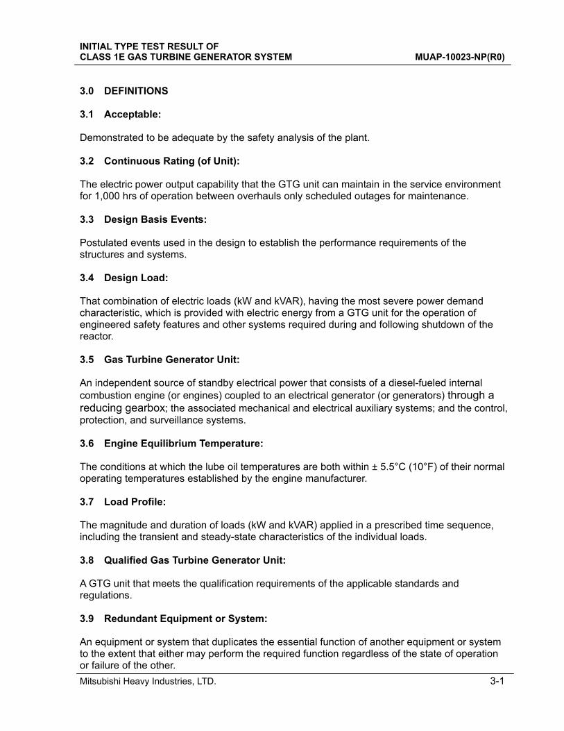
3.0 DEFINITIONS 3.1 Acceptable: Demonstrated to be adequate by the safety analysis of the plant. 3.2 Continuous Rating (of Unit): The electric power output capability that the GTG unit can maintain in the service environment for 1,000 hrs of operation between overhauls only scheduled outages for maintenance. 3.3 Design Basis Events: Postulated events used in the design to establish the performance requirements of the structures and systems. 3.4 Design Load: That combination of electric loads (kW and kVAR), having the most severe power demand characteristic, which is provided with electric energy from a GTG unit for the operation of engineered safety features and other systems required during and following shutdown of the reactor. 3.5 Gas Turbine Generator Unit: An independent source of standby electrical power that consists of a diesel-fueled internal combustion engine (or engines) coupled to an electrical generator (or generators) through a reducing gearbox; the associated mechanical and electrical auxiliary systems; and the control, protection, and surveillance systems. 3.6 Engine Equilibrium Temperature: The conditions at which the lube oil temperatures are both within ± 5.5°C (10°F) of their normal operating temperatures established by the engine manufacturer. 3.7 Load Profile: The magnitude and duration of loads (kW and kVAR) applied in a prescribed time sequence, including the transient and steady-state characteristics of the individual loads. 3.8 Qualified Gas Turbine Generator Unit: A GTG unit that meets the qualification requirements of the applicable standards and regulations. 3.9 Redundant Equipment or System: An equipment or system that duplicates the essential function of another equipment or system to the extent that either may perform the required function regardless of the state of operation or failure of the other.
INITIAL TYPE TEST RESULT OF CLASS 1E GAS TURBINE GENERATOR SYSTEM MUAP-10023-NP(R0)
Mitsubishi Heavy Industries, LTD. 3-2
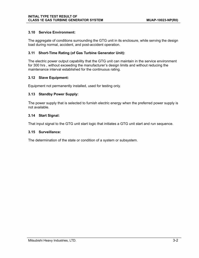
3.10 Service Environment: The aggregate of conditions surrounding the GTG unit in its enclosure, while serving the design load during normal, accident, and post-accident operation. 3.11 Short-Time Rating (of Gas Turbine Generator Unit): The electric power output capability that the GTG unit can maintain in the service environment for 300 hrs , without exceeding the manufacturer’s design limits and without reducing the maintenance interval established for the continuous rating. 3.12 Slave Equipment: Equipment not permanently installed, used for testing only. 3.13 Standby Power Supply: The power supply that is selected to furnish electric energy when the preferred power supply is not available. 3.14 Start Signal: That input signal to the GTG unit start logic that initiates a GTG unit start and run sequence. 3.15 Surveillance: The determination of the state or condition of a system or subsystem.
INITIAL TYPE TEST RESULT OF CLASS 1E GAS TURBINE GENERATOR SYSTEM MUAP-10023-NP(R0)
Mitsubishi Heavy Industries, LTD. 4-1
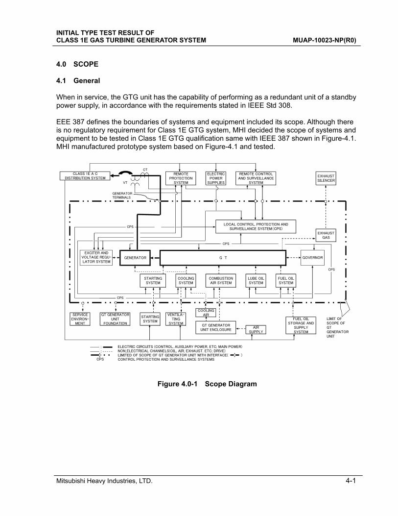
4.0 SCOPE 4.1 General When in service, the GTG unit has the capability of performing as a redundant unit of a standby power supply, in accordance with the requirements stated in IEEE Std 308. EEE 387 defines the boundaries of systems and equipment included its scope. Although there is no regulatory requirement for Class 1E GTG system, MHI decided the scope of systems and equipment to be tested in Class 1E GTG qualification same with IEEE 387 shown in Figure-4.1. MHI manufactured prototype system based on Figure-4.1 and tested.
CT
VT
; ELECTRIC CIRCUITS (CONTROL, AUXILIARY POWER, ETC; MAIN POWER); NON_ELECTRICAL CHANNELS(OIL, AIR, EXHAUST. ETC; DRIVE)
LIMITED OF SCOPE OF GT GENERATOR UNIT WITH INTERFACE( ) CONTROL PROTECTION AND SURVEILLANCE SYSTEMS
LOCAL CONTROL, PROTECTION ANDSURVEILLANCE SYSTEM(CPS)
FUEL OILSTORAGE AND
SUPPLYSYSTEM
CLASS 1E A CDISTRIBUTION SYSTEM
REMOTEPROTECTION
SYSTEM
ELECTRICPOWER
SUPPLIES
REMOTE CONTROLAND SURVEILLANCE
SYSTEM
EXHAUSTSILENCER
EXHAUSTGAS
SERVICEENVIRON-
MENT
CPS
GT GENERATORUNIT
FOUNDATION
FUEL OILSYSTEM
COMBUSTIONAIR SYSTEM
STARTINGSYSTEM
GENERATOR
COOLINGSYSTEM
GT GENERATORUNIT ENCLOSURE
G T
VENTILA-TING
SYSTEM
CPS
LIMIT OFSCOPE OFGTGENERATORUNIT
CPS
GENERATOR TERMINALS
CPS
AIRSUPPLY
COOLINGAIR
LUBE OILSYSTEM
EXCITER ANDVOLTAGE REG-ULATORSYSTEM
STARTINGSYSTEM
EXCITER ANDVOLTAGE REGU-LATOR SYSTEM
CPS
GOVERNOR
Figure 4.0-1 Scope Diagram
INITIAL TYPE TEST RESULT OF CLASS 1E GAS TURBINE GENERATOR SYSTEM MUAP-10023-NP(R0)
Mitsubishi Heavy Industries, LTD. 4-2
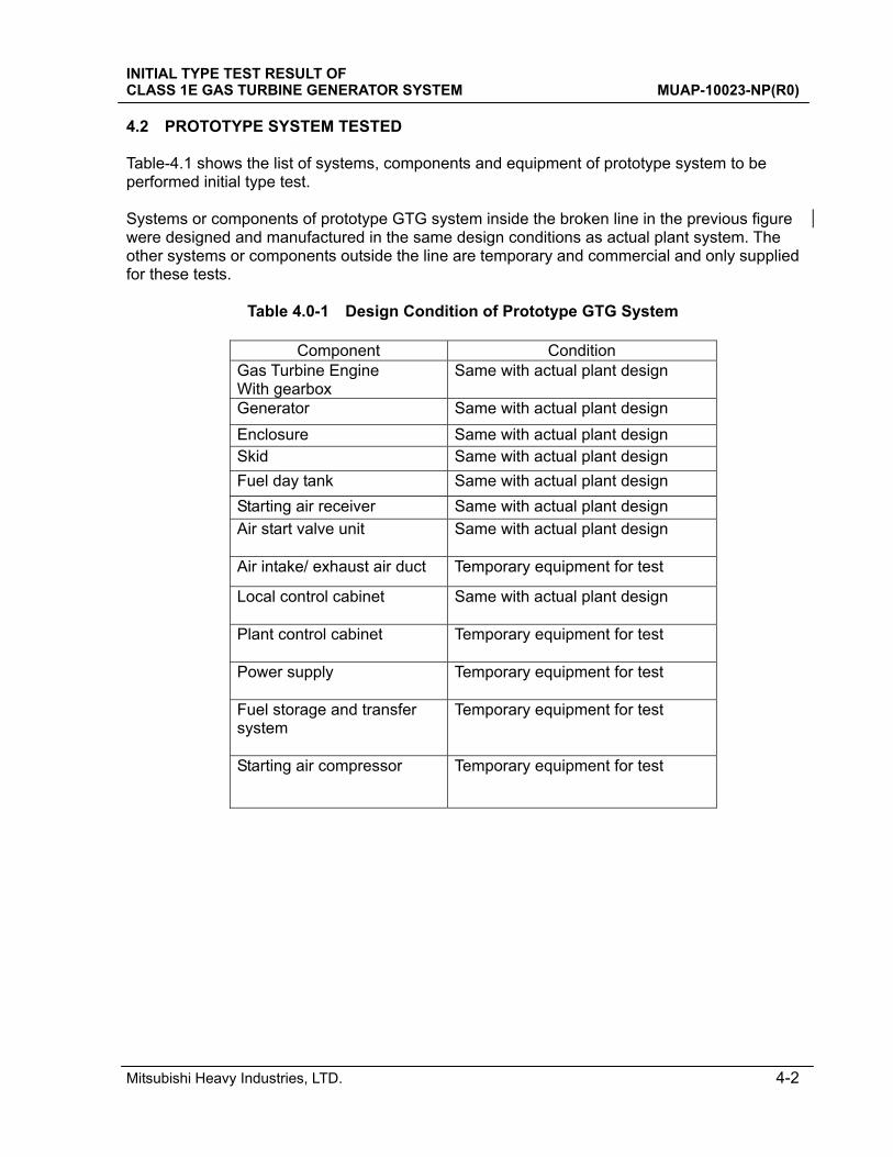
4.2 PROTOTYPE SYSTEM TESTED Table-4.1 shows the list of systems, components and equipment of prototype system to be performed initial type test. Systems or components of prototype GTG system inside the broken line in the previous figure were designed and manufactured in the same design conditions as actual plant system. The other systems or components outside the line are temporary and commercial and only supplied for these tests.
Table 4.0-1 Design Condition of Prototype GTG System
Component Condition Gas Turbine Engine With gearbox
Same with actual plant design
Generator Same with actual plant design
Enclosure Same with actual plant design Skid Same with actual plant design
Fuel day tank Same with actual plant design
Starting air receiver Same with actual plant design
Air start valve unit Same with actual plant design
Air intake/ exhaust air duct Temporary equipment for test
Local control cabinet
Same with actual plant design
Plant control cabinet
Temporary equipment for test
Power supply
Temporary equipment for test
Fuel storage and transfer system
Temporary equipment for test
Starting air compressor
Temporary equipment for test
INITIAL TYPE TEST RESULT OF CLASS 1E GAS TURBINE GENERATOR SYSTEM MUAP-10023-NP(R0)
Mitsubishi Heavy Industries, LTD. 5-1
5.0 PROTOTYPE SYSTEM 5.1 General When in service, the GTG unit has the capability of performing as a redundant unit of a standby power supply, in accordance with the requirements stated in IEEE Std 308. Also GTG system should be designed in accordance with IEEE Std 387. 5.2 System specification 5.2.1 Starting Time (1) Starting time of GTG is required within 100 seconds by safety design and analysis of
US-APWR. GTG to be reached set voltage and frequency, and GTG breaker should be closed within 100 seconds after starting signal is initiated.
(2) US-APWR GTG is reached set voltage and frequency within 40 seconds as its standard specification.
5.2.2 Rating The US–APWR GTG is rated as follows: 4500 kW Continuous @ 1,000 hrs Engine Overhaul Interval, 115°F Air Intake Temperature 4950 kW Short Time @ 300 hrs Engine Overhaul Interval, 115°F Air Intake Temperature 5.2.3 Fuel Oil System (1) Engine fuel will be commercial grade No. 2 fuel oil with limits as stated in ASTM Specification
D-396. (2) A direct engine/gearbox driven pump that pumps fuel oil from the day tank to the fuel
control valve is provided. (3) The welded steel day tank, to hold a total quantity of fuel required for 1.5 hours operation at
the continuous rating (2000 gallon rated) is provided. Tank is constructed in accordance with ASME Section Ⅲ, Class 3.
The system configuration is shown in Figure B.1.0-8. 5.2.4 Lubrication Oil System (1) A complete lube oil system is furnished to supply oil under pressure to the engine
bearings and reducing gear bearings. (2) A lube oil cooler is supplied to remove heat from the engine and speed reducer oil during
operation. The cooler shall be of the air to oil type and shall be driven by an electric motor driven fan, mounted close to the radiator core.
The system configuration is shown in Figure B.1.0-7.
INITIAL TYPE TEST RESULT OF CLASS 1E GAS TURBINE GENERATOR SYSTEM MUAP-10023-NP(R0)
Mitsubishi Heavy Industries, LTD. 5-2
5.2.5 Starting Air System The engine shall be capable of being started by compressed air within 100 seconds after signal for start. There are two air receivers in prototype system tested. In the actual plant design, four receivers capacity is designed that there is sufficient air at required pressure for three starts. The receivers are to be constructed in accordance with ASME Section Ⅲ, Class 3. The starting manifold assembly consists of reduction valves, pipes, gauges, Y-strainer, and control valves. This unit reduces air pressure at the inlet of this unit to the specified pressure (the secondary air pressure). The secondary air pressure depends on air starter's maximum limit pressure at inlet. The air compressor and compressor motor are designed as non safety related components. The system configuration of starting air system is shown in Figure B.1.0-9. 5.2.6 Intake/Exhaust Air System Air intake and exhaust systems consist of duct, silencer and ventilation fans. Drawing of tested system is shown in Figure B.1.0-10. Those will be designed in accordance with the site specific condition at actual plant project stage. 5.2.7 Enclosure/Skid The skid type base plate is provided of rolled steel sections welded together to form a rigid base for mounting the engine and generator systems above and suitable for bolting to a reinforced concrete foundation. 5.2.8 Control system One free standing local control panel having following function is furnished. ・ Manual GTG start/stop operation for maintenance ・ Individual start/stop operation of related GTG components for maintenance ・ Monitoring of GTG and related component parameters for maintenance The local control cabinet is actuated by sent signal from safety logic system of GTG which is digital control cabinet and not within the qualification scope. 5.2.7 Load Profiles The load profiles of US-APWR used as test condition are shown in Appendix A.
INITIAL TYPE TEST RESULT OF CLASS 1E GAS TURBINE GENERATOR SYSTEM MUAP-10023-NP(R0)
Mitsubishi Heavy Industries, LTD. 5-3
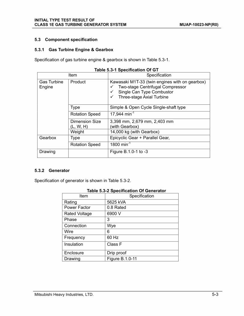
5.3 Component specification 5.3.1 Gas Turbine Engine & Gearbox Specification of gas turbine engine & gearbox is shown in Table 5.3-1.
Table 5.3-1 Specification Of GT Item Specification
Product
Kawasaki M1T-33 (twin engines with on gearbox) Two-stage Centrifugal Compressor Single Can Type Combustor Three-stage Axial Turbine
Type Simple & Open Cycle Single-shaft type
Rotation Speed 17,944 min-1
Dimension Size (L, W, H)
3,398 mm, 2,679 mm, 2,403 mm (with Gearbox)
Gas Turbine Engine
Weight 14,000 kg (with Gearbox) Type Epicyclic Gear + Parallel Gear, Gearbox
Rotation Speed 1800 min-1
Drawing Figure B.1.0-1 to -3
5.3.2 Generator Specification of generator is shown in Table 5.3-2.
Table 5.3-2 Specification Of Generator Item Specification
Rating 5625 kVA Power Factor 0.8 Rated
Rated Voltage 6900 V Phase 3
Connection Wye Wire 6 Frequency 60 Hz
Insulation Class F
Enclosure Drip proof Drawing Figure B.1.0-11
INITIAL TYPE TEST RESULT OF CLASS 1E GAS TURBINE GENERATOR SYSTEM MUAP-10023-NP(R0)
Mitsubishi Heavy Industries, LTD. 5-4
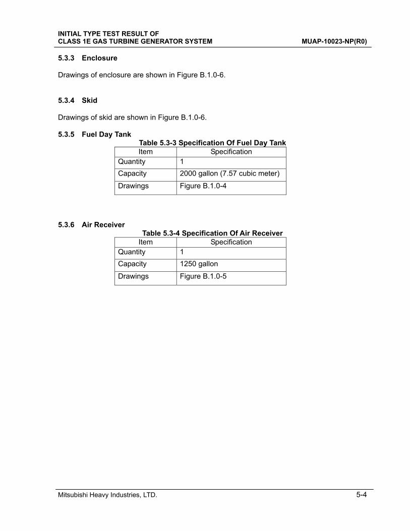
5.3.3 Enclosure Drawings of enclosure are shown in Figure B.1.0-6. 5.3.4 Skid Drawings of skid are shown in Figure B.1.0-6. 5.3.5 Fuel Day Tank
Table 5.3-3 Specification Of Fuel Day Tank Item Specification
Quantity 1
Capacity 2000 gallon (7.57 cubic meter)
Drawings Figure B.1.0-4
5.3.6 Air Receiver
Table 5.3-4 Specification Of Air Receiver Item Specification
Quantity 1
Capacity 1250 gallon
Drawings Figure B.1.0-5
INITIAL TYPE TEST RESULT OF CLASS 1E GAS TURBINE GENERATOR SYSTEM MUAP-10023-NP(R0)
Mitsubishi Heavy Industries, LTD. 6-1
6.0 INITIAL TYPE TEST 6.1 General The testing was in accordance with the initial type test portion of IEEEStd-387-1995 (section 6.2) and ISG-021 for application to gas turbine generator sets.
6.2 Load capability tests 6.2.1 Outline These tests demonstrate the capability of the GTG unit to carry the following rated loads at rated power factor for the period of time indicated, and to successfully reject load. One successful completion of the test sequence shall satisfy this particular requirement. 6.2.2 Procedure, Test Condition a) Load equal to the continuous rating shall be applied for the time required to reach engine
temperature equilibrium. b) Immediately following step a), the short-time rated load shall be applied for a period of 2 h
and the continuous rated load shall be applied of 22 h. The short-time rating load rejection test shall be performed.
c) Light-load or no-load capability as described shall be demonstrated by test. Light –load or no-load operation shall be followed by a load application ≧50% of the continuous kilowatt rating for a minimum of 0.5 h.
The detail test procedure is shown in Appendix D. 6.2.3 Acceptance Criteria 1) Maintain for duration while maintain normal temperature limits. 2) The load rejection test will be acceptable if the increase in speed of the engine does not
exceed 75% if the difference between nominal speed and the overspeed trip set point, or 15% above nominal, whichever is lower.
INITIAL TYPE TEST RESULT OF CLASS 1E GAS TURBINE GENERATOR SYSTEM MUAP-10023-NP(R0)
Mitsubishi Heavy Industries, LTD. 6-2
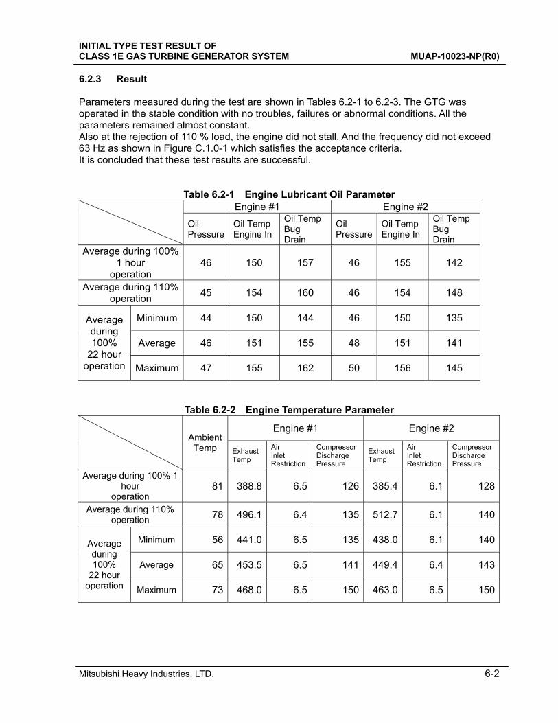
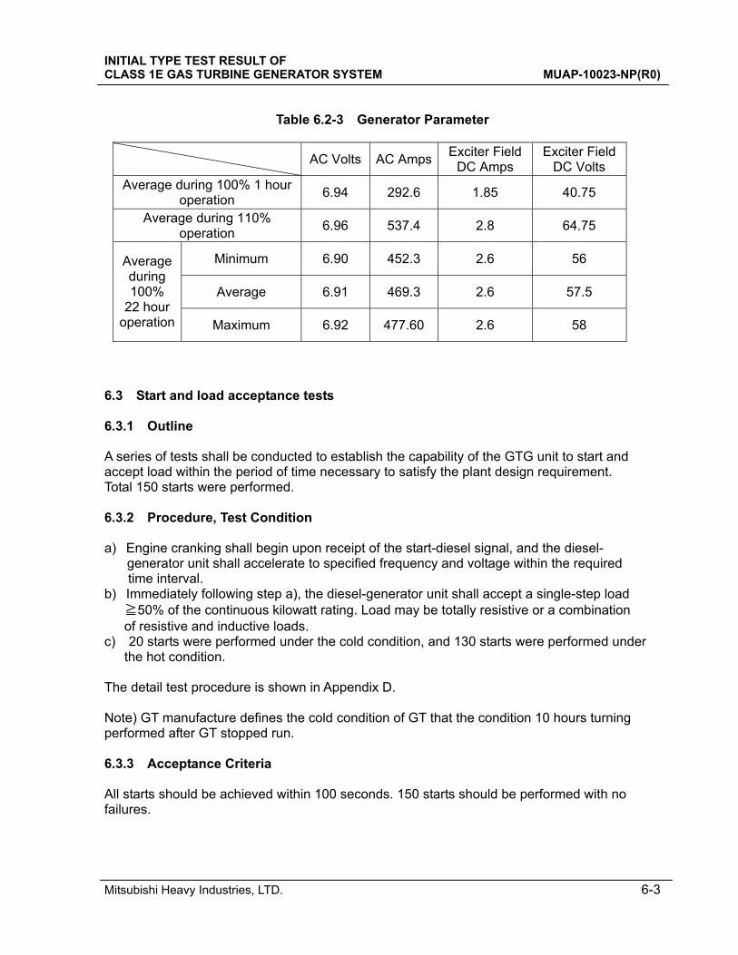
6.2.3 Result Parameters measured during the test are shown in Tables 6.2-1 to 6.2-3. The GTG was operated in the stable condition with no troubles, failures or abnormal conditions. All the parameters remained almost constant. Also at the rejection of 110 % load, the engine did not stall. And the frequency did not exceed 63 Hz as shown in Figure C.1.0-1 which satisfies the acceptance criteria. It is concluded that these test results are successful.
Table 6.2-1 Engine Lubricant Oil Parameter Engine #1 Engine #2
Oil Pressure
Oil Temp Engine In
Oil Temp Bug Drain
Oil Pressure
Oil Temp Engine In
Oil Temp Bug Drain
Average during 100% 1 hour
operation 46 150 157 46 155 142
Average during 110% operation
45 154 160 46 154 148
Minimum 44 150 144 46 150 135
Average 46 151 155 48 151 141
Average during 100%
22 hour operation Maximum 47 155 162 50 156 145
Table 6.2-2 Engine Temperature Parameter
Engine #1 Engine #2
Ambient Temp Exhaust
Temp
Air Inlet Restriction
Compressor Discharge Pressure
Exhaust Temp
Air Inlet Restriction
Compressor Discharge Pressure
Average during 100% 1 hour
operation 81 388.8 6.5 126 385.4 6.1 128
Average during 110% operation 78 496.1 6.4 135 512.7 6.1 140
Minimum 56 441.0 6.5 135 438.0 6.1 140
Average 65 453.5 6.5 141 449.4 6.4 143
Average during 100%
22 hour operation Maximum 73 468.0 6.5 150 463.0 6.5 150
INITIAL TYPE TEST RESULT OF CLASS 1E GAS TURBINE GENERATOR SYSTEM MUAP-10023-NP(R0)
Mitsubishi Heavy Industries, LTD. 6-3
Table 6.2-3 Generator Parameter
AC Volts AC AmpsExciter Field
DC Amps Exciter Field
DC Volts Average during 100% 1 hour
operation 6.94 292.6 1.85 40.75
Average during 110% operation
6.96 537.4 2.8 64.75
Minimum 6.90 452.3 2.6 56
Average 6.91 469.3 2.6 57.5
Average during 100%
22 hour operation Maximum 6.92 477.60 2.6 58
6.3 Start and load acceptance tests 6.3.1 Outline A series of tests shall be conducted to establish the capability of the GTG unit to start and accept load within the period of time necessary to satisfy the plant design requirement. Total 150 starts were performed. 6.3.2 Procedure, Test Condition a) Engine cranking shall begin upon receipt of the start-diesel signal, and the diesel-
generator unit shall accelerate to specified frequency and voltage within the required time interval.
b) Immediately following step a), the diesel-generator unit shall accept a single-step load ≧50% of the continuous kilowatt rating. Load may be totally resistive or a combination of resistive and inductive loads.
c) 20 starts were performed under the cold condition, and 130 starts were performed under the hot condition.
The detail test procedure is shown in Appendix D. Note) GT manufacture defines the cold condition of GT that the condition 10 hours turning performed after GT stopped run. 6.3.3 Acceptance Criteria All starts should be achieved within 100 seconds. 150 starts should be performed with no failures.
INITIAL TYPE TEST RESULT OF CLASS 1E GAS TURBINE GENERATOR SYSTEM MUAP-10023-NP(R0)
Mitsubishi Heavy Industries, LTD. 6-4
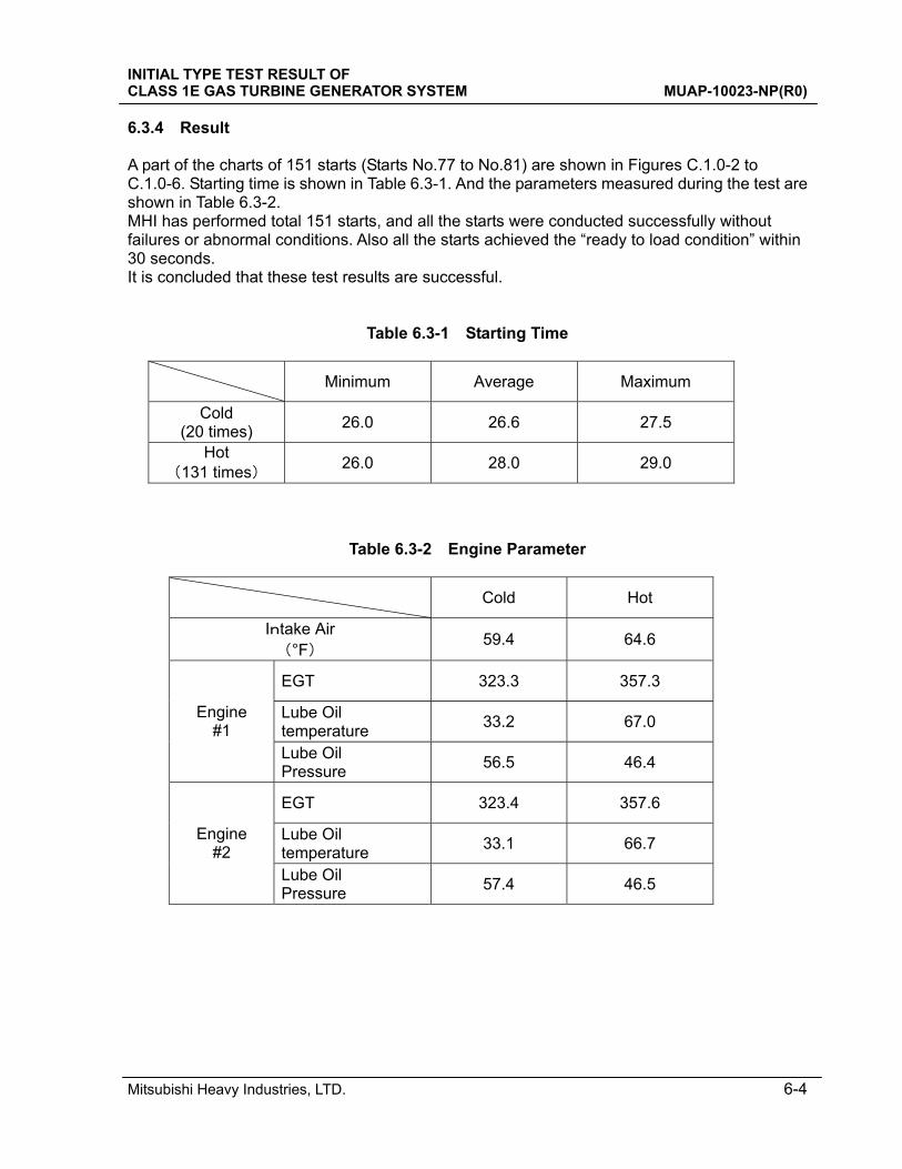
6.3.4 Result A part of the charts of 151 starts (Starts No.77 to No.81) are shown in Figures C.1.0-2 to C.1.0-6. Starting time is shown in Table 6.3-1. And the parameters measured during the test are shown in Table 6.3-2. MHI has performed total 151 starts, and all the starts were conducted successfully without failures or abnormal conditions. Also all the starts achieved the “ready to load condition” within 30 seconds. It is concluded that these test results are successful.
Table 6.3-1 Starting Time
Minimum Average Maximum
Cold (20 times)
26.0 26.6 27.5
Hot (131 times)
26.0 28.0 29.0
Table 6.3-2 Engine Parameter
Cold Hot
Intake Air (°F)
59.4 64.6
EGT 323.3 357.3
Lube Oil temperature
33.2 67.0 Engine
#1 Lube Oil Pressure
56.5 46.4
EGT 323.4 357.6
Lube Oil temperature
33.1 66.7 Engine
#2 Lube Oil Pressure
57.4 46.5
INITIAL TYPE TEST RESULT OF CLASS 1E GAS TURBINE GENERATOR SYSTEM MUAP-10023-NP(R0)
Mitsubishi Heavy Industries, LTD. 6-5
6.4 Margin tests 6.4.1 Outline Tests shall be conducted to demonstrate the GTG unit capability to start and carry loads that are greater than the magnitude of the most severe step load within the plant design load profile, including step changes above base load. 6.4.2 Procedure, Test Condition At least two margin tests shall be performed using either the same or different load arrangement. A margin test load at least 10% greater than the magnitude of the most severe single-step load within the load profile is considered sufficient for the margin test. The frequency and voltage excursions recorded may exceed those values specified for the plant design load. The detail test procedure is shown in Appendix D. 6.4.3 Acceptance Criteria a) Demonstrate the ability of the generator and excitation system to accept the margin test
load (usually the low power factor, high inrush, and high starting current of a pump motor) without experiencing instability resulting in generator voltage collapse, or significant evidence of the inability of the voltage to recover.
b) Demonstrate that there is sufficient engine torque available to prevent engine stall, and to permit the engine speed to recover, when experiencing the margin test load.
6.4.4 Result Charts of two margin tests are shown in Figures C.1.0-7 to C.1.0-8. The GTG did not stall in the two tests. Although the voltage and frequency dropped just after loaded, they recovered within 2 seconds as shown in Figures C.1.0-7 and Figure C.1.0-8. It is concluded that these test results are successful.
INITIAL TYPE TEST RESULT OF CLASS 1E GAS TURBINE GENERATOR SYSTEM MUAP-10023-NP(R0)
Mitsubishi Heavy Industries, LTD. 6-6
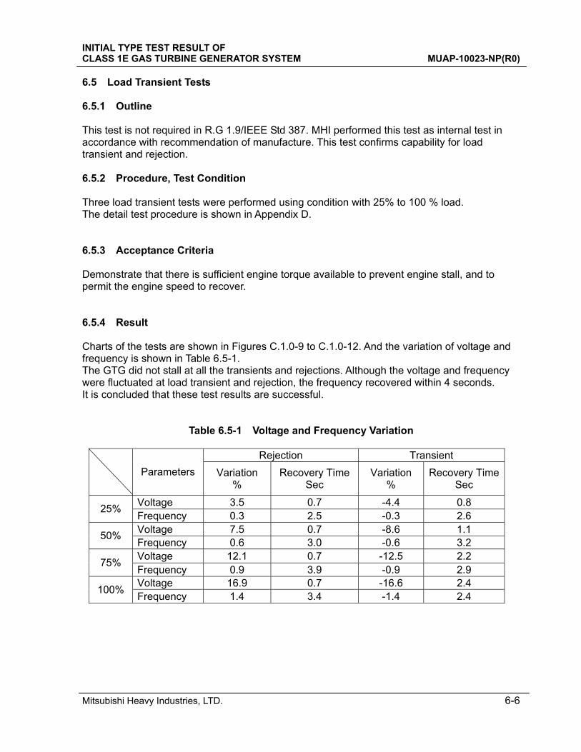
6.5 Load Transient Tests 6.5.1 Outline This test is not required in R.G 1.9/IEEE Std 387. MHI performed this test as internal test in accordance with recommendation of manufacture. This test confirms capability for load transient and rejection. 6.5.2 Procedure, Test Condition Three load transient tests were performed using condition with 25% to 100 % load. The detail test procedure is shown in Appendix D. 6.5.3 Acceptance Criteria Demonstrate that there is sufficient engine torque available to prevent engine stall, and to permit the engine speed to recover. 6.5.4 Result Charts of the tests are shown in Figures C.1.0-9 to C.1.0-12. And the variation of voltage and frequency is shown in Table 6.5-1. The GTG did not stall at all the transients and rejections. Although the voltage and frequency were fluctuated at load transient and rejection, the frequency recovered within 4 seconds. It is concluded that these test results are successful.
Table 6.5-1 Voltage and Frequency Variation
Rejection Transient
Parameters Variation %
Recovery TimeSec
Variation %
Recovery TimeSec
Voltage 3.5 0.7 -4.4 0.8 25%
Frequency 0.3 2.5 -0.3 2.6 Voltage 7.5 0.7 -8.6 1.1
50% Frequency 0.6 3.0 -0.6 3.2 Voltage 12.1 0.7 -12.5 2.2
75% Frequency 0.9 3.9 -0.9 2.9 Voltage 16.9 0.7 -16.6 2.4
100% Frequency 1.4 3.4 -1.4 2.4
INITIAL TYPE TEST RESULT OF CLASS 1E GAS TURBINE GENERATOR SYSTEM MUAP-10023-NP(R0)
Mitsubishi Heavy Industries, LTD. 8-1
7.0 CONSIDERATION Based on the test results provided in this Technical Report it is concluded that the GTG unit provided by KHI and Class 1E qualified by Engine System Inc. (ESI) was successful in the initial type test. (1) US-APWR GTG system was successful in all three initial type tests, “Load Capability Test”,
“Start and Load Acceptance Test” and “Margin Test”. (2) During “Load Capability Test”, GTG was operated without failures or troubles. Each
parameter such as engine lubricant oil temperature, engine compressor pressure, exhaust gas temperature (EGT) and others was almost constant during 100% operation. During 110% operation EGT remained stable although it was higher than 100% operation.
(3) The 150 starts test was carried out with no failures or troubles. “Ready to Load” time of all starts was less than 30 seconds. The rotation speed increased at almost the same rate between all the tests conducted. When comparing the starting time between cold and hot conditions, the average starting time was shorter at the cold condition. This is because the governor is controlled by EGT to supply more fuel in the cold condition and start the GTG faster. Such design properties were confirmed during this test.
(4) GTGs rotate at 18000min-1 and GD2 is large. Therefore, transient load changes do not have much impact on rotation speed and also recovering from the rotation speed variation is quick because the governor is controlled by rotation speed and EGT. At 100% load transient/rejection, the frequency variation was -1.4 %/ 1.4 % respectively, which is very small and the recovery to the rated frequency was 2.4 seconds/ 3.5 seconds. Results were achieved which would not have happened in DG tests. This GTG’s frequency stabilizing capability is one of the advantages for GTG and well known in the specification of GTGs. It can be said that GTG is well qualified for nuclear power plant Class 1E emergency power sources which assume loading of large loads in sequence. It can be concluded that the Class 1E test proves this GTG’s capability and was meaningful.
INITIAL TYPE TEST RESULT OF CLASS 1E GAS TURBINE GENERATOR SYSTEM MUAP-10023-NP(R0)
Mitsubishi Heavy Industries, LTD. 8-1
8.0 CONCLUSIONS Based on the results provided in this Technical Report, it is concluded that the US-APWR GTG unit is successful in the initial type test and meets the requirements for Class 1E emergency power sources described in R.G 1.9 and IEEE Std-387.
INITIAL TYPE TEST RESULT OF CLASS 1E GAS TURBINE GENERATOR SYSTEM MUAP-10023-NP(R0)
Mitsubishi Heavy Industries, LTD. 9-1
9.0 REFERENCES In this section, references in this technical report except for applicable codes, standards and regulatory guidance in section 2 are listed. 1. ASME Section Ⅲ, Class 3 2. The requirements of MNES, Quality Assurance Administrative and System Requirements
(Nuclear) 3. The requirements of MNES, Quality Assurance Administrative and System Requirements for
Safety Related Electrical Equipment 4. MUAP-07024, Qualification and Test Plan of Class 1E Gas Turbine Generator System
INITIAL TYPE TEST RESULT OF CLASS 1E GAS TURBINE GENERATOR SYSTEM MUAP-10023-NP(R0)
Mitsubishi Heavy Industries, LTD. A-1
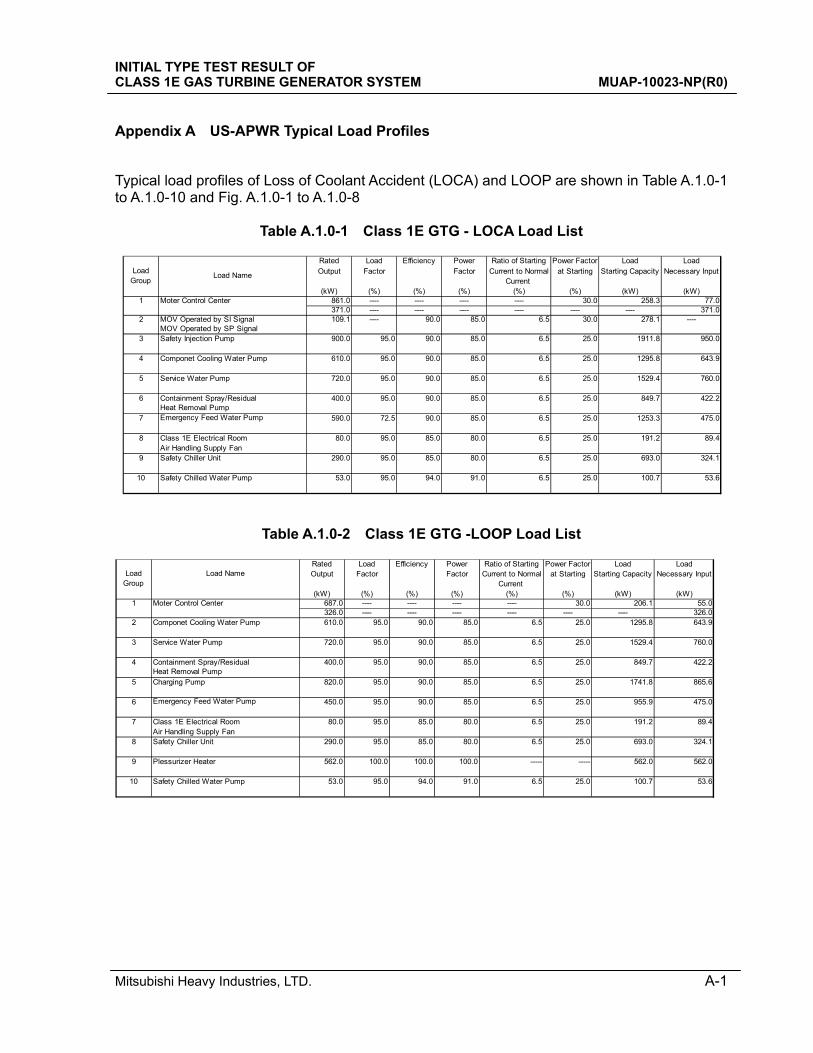
Appendix A US-APWR Typical Load Profiles
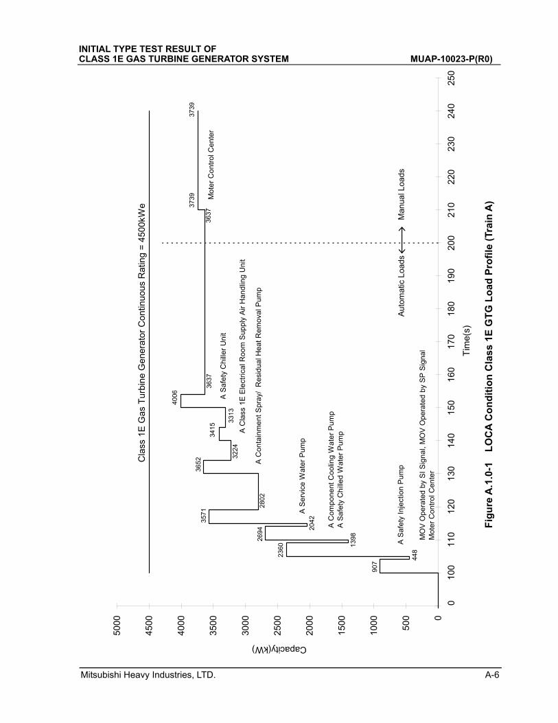
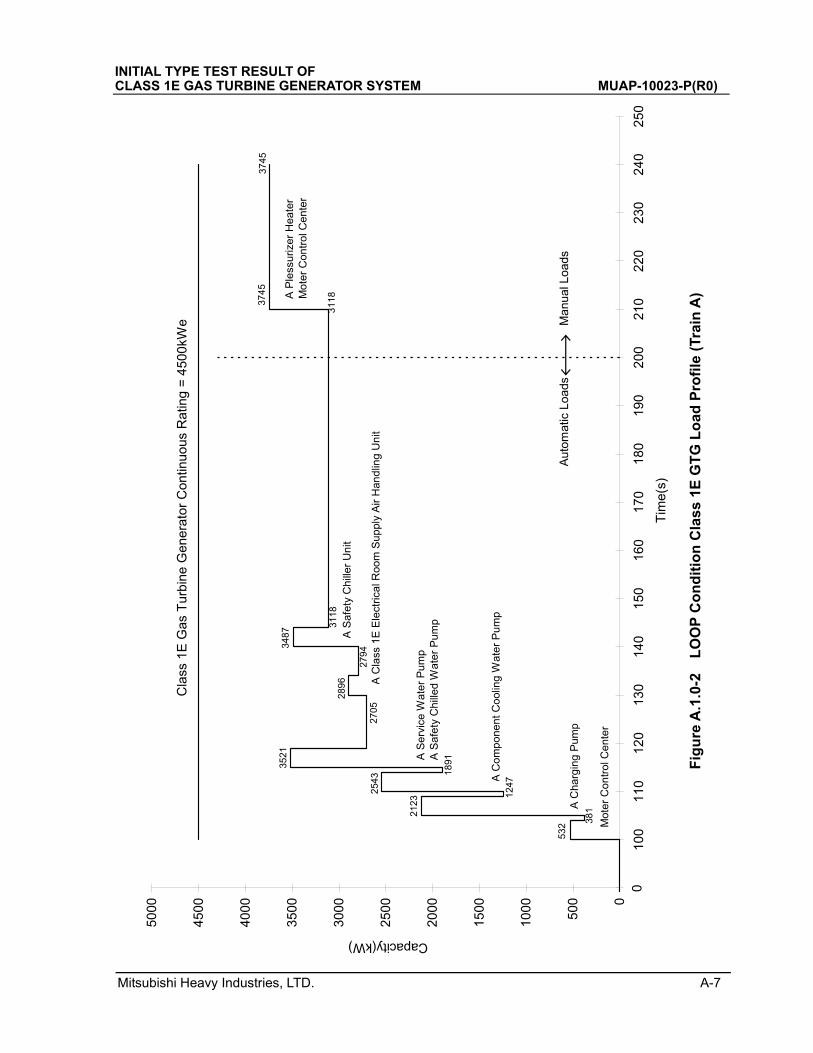
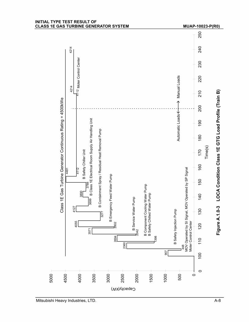
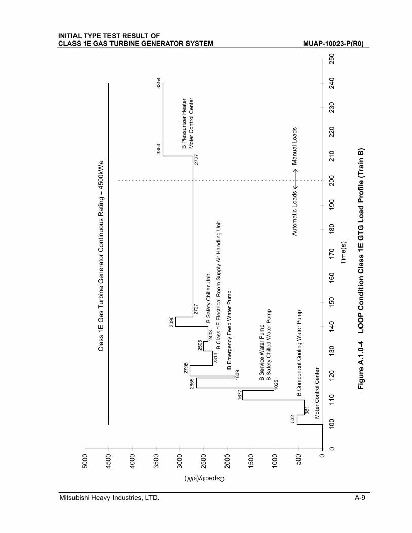
Typical load profiles of Loss of Coolant Accident (LOCA) and LOOP are shown in Table A.1.0-1 to A.1.0-10 and Fig. A.1.0-1 to A.1.0-8
Table A.1.0-1 Class 1E GTG - LOCA Load List
Table A.1.0-2 Class 1E GTG -LOOP Load List
Rated Load Efficiency Power Ratio of Starting Power Factor Load LoadOutput Factor Factor Current to Normal at Starting Starting Capacity Necessary Input
Current (kW) (%) (%) (%) (%) (%) (kW) (kW)
1 Moter Control Center 861.0 ---- ---- ---- ---- 30.0 258.3 77.0371.0 ---- ---- ---- ---- ---- ---- 371.0
2 MOV Operated by SI Signal 109.1 ---- 90.0 85.0 6.5 30.0 278.1 ----MOV Operated by SP Signal
3 Safety Injection Pump 900.0 95.0 90.0 85.0 6.5 25.0 1911.8 950.0
4 Componet Cooling Water Pump 610.0 95.0 90.0 85.0 6.5 25.0 1295.8 643.9
5 Service Water Pump 720.0 95.0 90.0 85.0 6.5 25.0 1529.4 760.0
6 400.0 95.0 90.0 85.0 6.5 25.0 849.7 422.2
7 590.0 72.5 90.0 85.0 6.5 25.0 1253.3 475.0
8 Class 1E Electrical Room 80.0 95.0 85.0 80.0 6.5 25.0 191.2 89.4Air Handling Supply Fan
9 Safety Chiller Unit 290.0 95.0 85.0 80.0 6.5 25.0 693.0 324.1
10 Safety Chilled Water Pump 53.0 95.0 94.0 91.0 6.5 25.0 100.7 53.6
Load NameLoad
Group
Containment Spray/ResidualHeat Removal PumpEmergency Feed Water Pump
Rated Load Efficiency Power Ratio of Starting Power Factor Load LoadOutput Factor Factor Current to Normal at Starting Starting Capacity Necessary Input
Current (kW) (%) (%) (%) (%) (%) (kW) (kW)
1 Moter Control Center 687.0 ---- ---- ---- ---- 30.0 206.1 55.0326.0 ---- ---- ---- ---- ---- ---- 326.0
2 Componet Cooling Water Pump 610.0 95.0 90.0 85.0 6.5 25.0 1295.8 643.9
3 Service Water Pump 720.0 95.0 90.0 85.0 6.5 25.0 1529.4 760.0
4 400.0 95.0 90.0 85.0 6.5 25.0 849.7 422.2
5 Charging Pump 820.0 95.0 90.0 85.0 6.5 25.0 1741.8 865.6
6 450.0 95.0 90.0 85.0 6.5 25.0 955.9 475.0
7 Class 1E Electrical Room 80.0 95.0 85.0 80.0 6.5 25.0 191.2 89.4Air Handling Supply Fan
8 Safety Chiller Unit 290.0 95.0 85.0 80.0 6.5 25.0 693.0 324.1
9 Plessurizer Heater 562.0 100.0 100.0 100.0 ----- ----- 562.0 562.0
10 Safety Chilled Water Pump 53.0 95.0 94.0 91.0 6.5 25.0 100.7 53.6
Emergency Feed Water Pump
Containment Spray/ResidualHeat Removal Pump
Load NameLoadGroup
INITIAL TYPE TEST RESULT OF CLASS 1E GAS TURBINE GENERATOR SYSTEM MUAP-10023-NP(R0)
Mitsubishi Heavy Industries, LTD. A-2
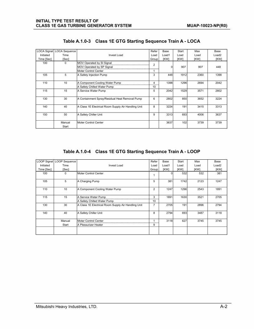
Table A.1.0-3 Class 1E GTG Starting Sequence Train A - LOCA
Table A.1.0-4 Class 1E GTG Starting Sequence Train A - LOOP
LOCA Signal LOCA Sequence Refer Base Start Max Base
Initiated Time Invest Load Load Load1 Load Load Load2
Time [Sec] [Sec] Group [KW] [KW] [KW] [KW]
100 0 MOV Operated by SI Signal
MOV Operated by SP Signal 0 907 907 448
Moter Control Center 1
105 5 A Safety Injection Pump 3 448 1912 2360 1398
110 10 A Component Cooling Water Pump 4 1398 1296 2694 2042
A Safety Chilled Water Pump 10
115 15 A Service Water Pump 5 2042 1529 3571 2802
130 30 A Containment Spray/Residual Heat Removal Pump 6 2802 850 3652 3224
140 40 A Class 1E Electrical Room Supply Air Handling Unit 8 3224 191 3415 3313
150 50 A Safety Chiller Unit 9 3313 693 4006 3637
Manual Moter Control Center 3637 102 3739 3739
Start
2
LOOP Signal LOOP Sequence Refer Base Start Max Base
Initiated Time Invest Load Load Load1 Load Load Load2
Time [Sec] [Sec] Group [KW] [KW] [KW] [KW]
100 0 Moter Control Center 0 532 532 381
105 5 A Charging Pump 5 381 1742 2123 1247
110 10 A Component Cooling Water Pump 2 1247 1296 2543 1891
115 15 A Service Water Pump 3 1891 1630 3521 2705
A Safety Chilled Water Pump 10
130 30 A Class 1E Electrical Room Supply Air Handling Unit 7 2705 191 2896 2794
140 40 A Safety Chiller Unit 8 2794 693 3487 3118
Manual Moter Control Center 1 3118 627 3745 3745
Start A Plessurizer Heater 9
1
INITIAL TYPE TEST RESULT OF CLASS 1E GAS TURBINE GENERATOR SYSTEM MUAP-10023-NP(R0)
Mitsubishi Heavy Industries, LTD. A-3
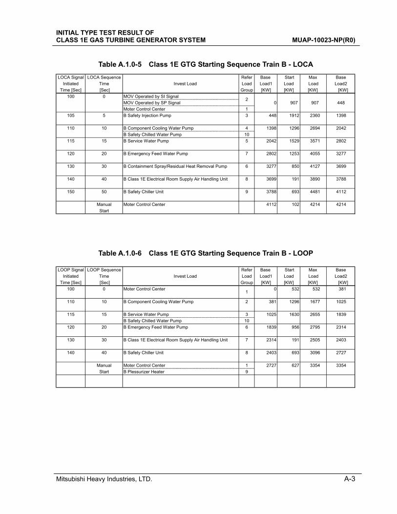
Table A.1.0-5 Class 1E GTG Starting Sequence Train B - LOCA
Table A.1.0-6 Class 1E GTG Starting Sequence Train B - LOOP
LOCA Signal LOCA Sequence Refer Base Start Max Base
Initiated Time Invest Load Load Load1 Load Load Load2
Time [Sec] [Sec] Group [KW] [KW] [KW] [KW]
100 0 MOV Operated by SI Signal
MOV Operated by SP Signal 0 907 907 448
Moter Control Center 1
105 5 B Safety Injection Pump 3 448 1912 2360 1398
110 10 B Component Cooling Water Pump 4 1398 1296 2694 2042
B Safety Chilled Water Pump 10
115 15 B Service Water Pump 5 2042 1529 3571 2802
120 20 B Emergency Feed Water Pump 7 2802 1253 4055 3277
130 30 B Containment Spray/Residual Heat Removal Pump 6 3277 850 4127 3699
140 40 B Class 1E Electrical Room Supply Air Handling Unit 8 3699 191 3890 3788
150 50 B Safety Chiller Unit 9 3788 693 4481 4112
Manual Moter Control Center 4112 102 4214 4214
Start
2
LOOP Signal LOOP Sequence Refer Base Start Max Base
Initiated Time Invest Load Load Load1 Load Load Load2
Time [Sec] [Sec] Group [KW] [KW] [KW] [KW]
100 0 Moter Control Center 0 532 532 381
110 10 B Component Cooling Water Pump 2 381 1296 1677 1025
115 15 B Service Water Pump 3 1025 1630 2655 1839
B Safety Chilled Water Pump 10
120 20 B Emergency Feed Water Pump 6 1839 956 2795 2314
130 30 B Class 1E Electrical Room Supply Air Handling Unit 7 2314 191 2505 2403
140 40 B Safety Chiller Unit 8 2403 693 3096 2727
Manual Moter Control Center 1 2727 627 3354 3354
Start B Plessurizer Heater 9
1
INITIAL TYPE TEST RESULT OF CLASS 1E GAS TURBINE GENERATOR SYSTEM MUAP-10023-NP(R0)
Mitsubishi Heavy Industries, LTD. A-4
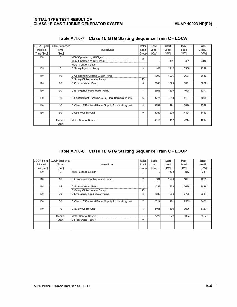
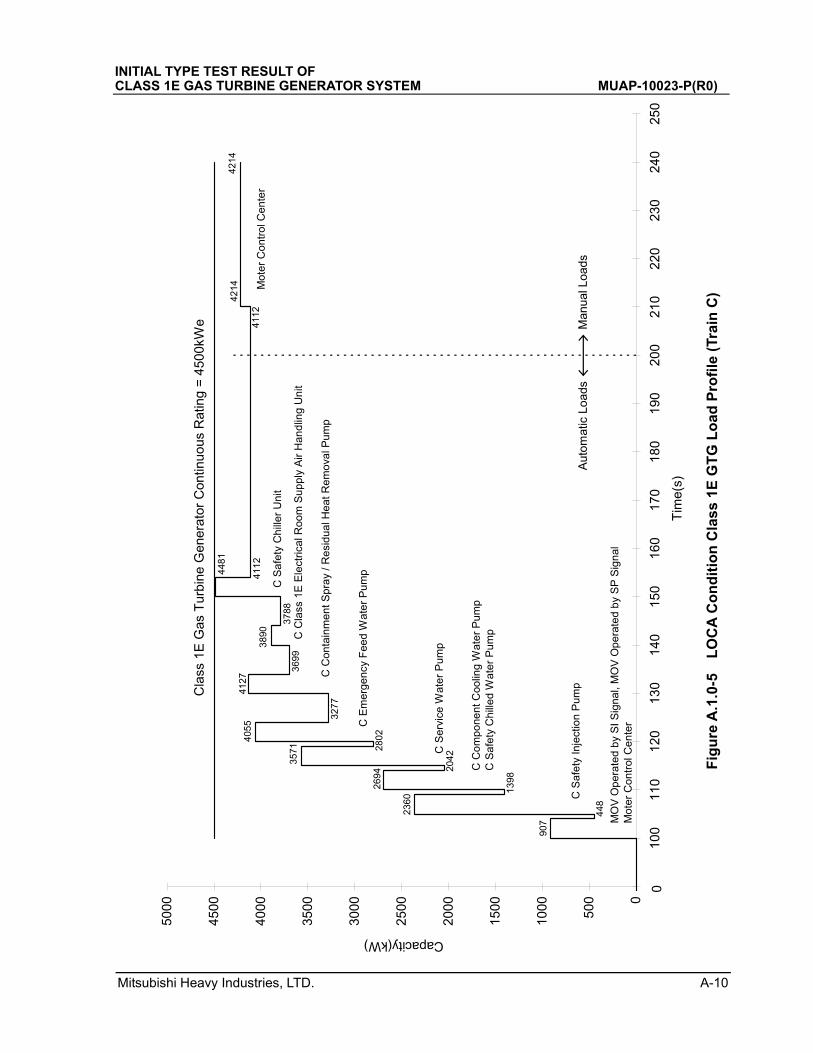
Table A.1.0-7 Class 1E GTG Starting Sequence Train C - LOCA
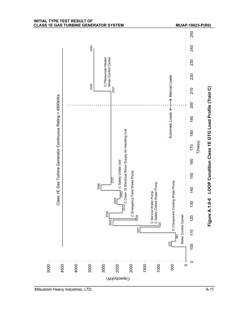
Table A.1.0-8 Class 1E GTG Starting Sequence Train C - LOOP
LOCA Signal LOCA Sequence Refer Base Start Max Base
Initiated Time Invest Load Load Load1 Load Load Load2
Time [Sec] [Sec] Group [KW] [KW] [KW] [KW]
100 0 MOV Operated by SI Signal
MOV Operated by SP Signal 0 907 907 448
Moter Control Center 1
105 5 C Safety Injection Pump 3 448 1912 2360 1398
110 10 C Component Cooling Water Pump 4 1398 1296 2694 2042
C Safety Chilled Water Pump 10
115 15 C Service Water Pump 5 2042 1529 3571 2802
120 20 C Emergency Feed Water Pump 7 2802 1253 4055 3277
130 30 C Containment Spray/Residual Heat Removal Pump 6 3277 850 4127 3699
140 40 C Class 1E Electrical Room Supply Air Handling Unit 8 3699 191 3890 3788
150 50 C Safety Chiller Unit 9 3788 693 4481 4112
Manual Moter Control Center 4112 102 4214 4214
Start
2
LOOP Signal LOOP Sequence Refer Base Start Max Base
Initiated Time Invest Load Load Load1 Load Load Load2
Time [Sec] [Sec] Group [KW] [KW] [KW] [KW]
100 0 Moter Control Center 0 532 532 381
110 10 C Component Cooling Water Pump 2 381 1296 1677 1025
115 15 C Service Water Pump 3 1025 1630 2655 1839
C Safety Chilled Water Pump 10
120 20 C Emergency Feed Water Pump 6 1839 956 2795 2314
130 30 C Class 1E Electrical Room Supply Air Handling Unit 7 2314 191 2505 2403
140 40 C Safety Chiller Unit 8 2403 693 3096 2727
Manual Moter Control Center 1 2727 627 3354 3354
Start C Plessurizer Heater 9
1
INITIAL TYPE TEST RESULT OF CLASS 1E GAS TURBINE GENERATOR SYSTEM MUAP-10023-NP(R0)
Mitsubishi Heavy Industries, LTD. A-5
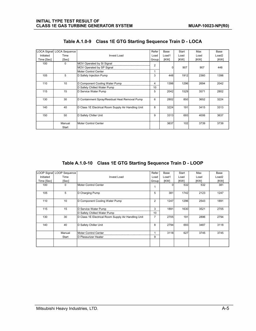
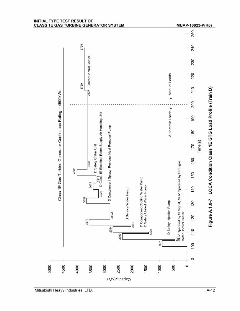
Table A.1.0-9 Class 1E GTG Starting Sequence Train D - LOCA
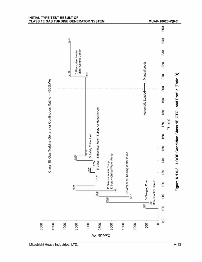
Table A.1.0-10 Class 1E GTG Starting Sequence Train D - LOOP
LOCA Signal LOCA Sequence Refer Base Start Max Base
Initiated Time Invest Load Load Load1 Load Load Load2
Time [Sec] [Sec] Group [KW] [KW] [KW] [KW]
100 0 MOV Operated by SI Signal
MOV Operated by SP Signal 0 907 907 448
Moter Control Center 1
105 5 D Safety Injection Pump 3 448 1912 2360 1398
110 10 D Component Cooling Water Pump 4 1398 1296 2694 2042
D Safety Chilled Water Pump 10
115 15 D Service Water Pump 5 2042 1529 3571 2802
130 30 D Containment Spray/Residual Heat Removal Pump 6 2802 850 3652 3224
140 40 D Class 1E Electrical Room Supply Air Handling Unit 8 3224 191 3415 3313
150 50 D Safety Chiller Unit 9 3313 693 4006 3637
Manual Moter Control Center 3637 102 3739 3739
Start
2
LOOP Signal LOOP Sequence Refer Base Start Max Base
Initiated Time Invest Load Load Load1 Load Load Load2
Time [Sec] [Sec] Group [KW] [KW] [KW] [KW]
100 0 Moter Control Center 0 532 532 381
105 5 D Charging Pump 5 381 1742 2123 1247
110 10 D Component Cooling Water Pump 2 1247 1296 2543 1891
115 15 D Service Water Pump 3 1891 1630 3521 2705
D Safety Chilled Water Pump 10
130 30 D Class 1E Electrical Room Supply Air Handling Unit 7 2705 191 2896 2794
140 40 D Safety Chiller Unit 8 2794 693 3487 3118
Manual Moter Control Center 1 3118 627 3745 3745
Start D Plessurizer Heater 9
1
Mitsubishi Heavy Industries, LTD. A-6
INITIAL TYPE TEST RESULT OF CLASS 1E GAS TURBINE GENERATOR SYSTEM MUAP-10023-P(R0)
F
igu
re A
.1.0
-1
LO
CA
Co
nd
itio
n C
lass
1E
GT
G L
oad
Pro
file
(Tr
ain
A)
3739
3739
3637
3637
4006
3313
3415
3224
3652
2802
3571
2042
2694
1398
2360
448
907
0
500
1000
1500
2000
2500
3000
3500
4000
4500
5000
9010
011
012
013
014
015
016
017
018
019
020
021
022
023
024
025
0
Tim
e(s)
Capacity(kW)
Cla
ss 1
E G
as T
urbi
ne G
ener
ator
Con
tinuo
us R
atin
g =
450
0kW
e
Aut
omat
ic L
oads
Man
ual L
oads
MO
V O
pera
ted
by
SI
Sig
na
l, M
OV
Ope
rate
d b
y S
P S
igna
lM
ote
r C
ont
rol C
ente
r
A S
afe
ty I
nje
ctio
n P
um
p
A C
ompo
ne
nt C
oo
ling
Wa
ter
Pu
mp
A S
afe
ty C
hill
ed
Wa
ter
Pu
mp
A S
erv
ice
Wa
ter
Pu
mp
A C
onta
inm
en
t Spr
ay/
Res
idu
al H
ea
t Rem
ova
l Pu
mp
A C
lass
1E
Ele
ctri
cal R
oom
Sup
ply
Air
Han
dlin
g U
nit
A S
afe
ty C
hill
er
Un
it
Mo
ter
Co
ntr
ol C
ent
er
0
Mitsubishi Heavy Industries, LTD. A-7
INITIAL TYPE TEST RESULT OF CLASS 1E GAS TURBINE GENERATOR SYSTEM MUAP-10023-P(R0)
F
igu
re A
.1.0
-2
LO
OP
Co
nd
itio
n C
lass
1E
GT
G L
oad
Pro
file
(Tr
ain
A)
532 38
12123
1247
2543
189135
21
2705
2896
2794
3487
3118
311837
4537
45
0
500
1000
1500
2000
2500
3000
3500
4000
4500
5000
9010
011
012
013
014
015
016
017
018
019
020
021
022
023
024
025
0
Tim
e(s)
Capacity(kW)
Cla
ss 1
E G
as T
urbi
ne G
ener
ator
Con
tinuo
us R
atin
g =
450
0kW
e
Aut
omat
ic L
oads
Man
ual L
oads
Mot
er
Co
ntr
ol C
ent
er
A C
harg
ing
Pum
p
A C
om
po
nen
t C
ool
ing
Wa
ter
Pu
mp
A S
erv
ice
Wa
ter
Pum
pA
Sa
fety
Ch
ille
d W
ate
r P
um
p
A C
lass
1E
Ele
ctri
cal R
oom
Su
ppl
y A
ir H
and
ling
Un
it
A S
afe
ty C
hill
er
Un
it
A P
less
uriz
er H
eate
rM
ote
r C
ontr
ol C
en
ter
0
Mitsubishi Heavy Industries, LTD. A-8
INITIAL TYPE TEST RESULT OF CLASS 1E GAS TURBINE GENERATOR SYSTEM MUAP-10023-P(R0)
F
igu
re A
.1.0
-3
LO
CA
Co
nd
itio
n C
lass
1E
GT
G L
oad
Pro
file
(Tr
ain
B)
907
448
2360
1398
2694
2042
3571
2802
4055
3277
4127
3699
3890
3788
4481
4112
411242
1442
14
0
500
1000
1500
2000
2500
3000
3500
4000
4500
5000
9010
011
012
013
014
015
016
017
018
019
020
021
022
023
024
025
0
Tim
e(s)
Capacity(kW)
Cla
ss 1
E G
as T
urbi
ne G
ener
ator
Con
tinuo
us R
atin
g =
450
0kW
e
Aut
omat
ic L
oads
Man
ual L
oads
MO
V O
per
ate
d b
y S
I S
ign
al,
MO
V O
per
ate
d b
y S
P S
ign
alM
ote
r C
on
trol
Ce
nte
r
B S
afe
ty In
ject
ion
Pum
p
B C
om
po
nen
t Coo
ling
Wat
er
Pu
mp
B S
afe
ty C
hille
d W
ate
r P
um
p
B S
erv
ice
Wat
er
Pum
p
B E
mer
ge
ncy
Fe
ed
Wa
ter
Pum
p
B C
onta
inm
en
t S
pra
y / R
esid
ual
He
at R
emov
al P
um
p
B C
lass
1E
Ele
ctri
cal R
oom
Sup
ply
Air
Han
dlin
g U
nit
Mo
ter
Co
ntr
ol C
en
ter
B S
afe
ty C
hill
er
Un
it
0
Mitsubishi Heavy Industries, LTD. A-9
INITIAL TYPE TEST RESULT OF CLASS 1E GAS TURBINE GENERATOR SYSTEM MUAP-10023-P(R0)
F
igu
re A
.1.0
-4
LO
OP
Co
nd
itio
n C
lass
1E
GT
G L
oad
Pro
file
(Tr
ain
B)
532
381
1677
1025
2655
183927
95
2314
2505
2403
3096
2727
2727
3354
3354
0
500
1000
1500
2000
2500
3000
3500
4000
4500
5000
9010
011
012
013
014
015
016
017
018
019
020
021
022
023
024
025
0
Tim
e(s)
Capacity(kW)
Cla
ss 1
E G
as T
urbi
ne G
ener
ator
Con
tinuo
us R
atin
g =
450
0kW
e
Aut
omat
ic L
oads
Man
ual L
oads
Mo
ter
Co
ntro
l Cen
ter
B C
om
pon
ent
Co
olin
g W
ate
r P
um
p
B S
ervi
ce W
ate
r P
um
pB
Sa
fety
Ch
ille
d W
ate
r P
um
p
B E
mer
ge
ncy
Fe
ed
Wa
ter
Pum
p
B S
afe
ty C
hille
r U
nit
B P
less
uriz
er
Hea
ter
Mo
ter
Co
ntro
l Cen
ter
B C
lass
1E
Ele
ctric
al R
oo
m S
up
ply
Air
Ha
nd
ling
Un
it
0
Mitsubishi Heavy Industries, LTD. A-10
INITIAL TYPE TEST RESULT OF CLASS 1E GAS TURBINE GENERATOR SYSTEM MUAP-10023-P(R0)
F
igu
re A
.1.0
-5
LO
CA
Co
nd
itio
n C
lass
1E
GT
G L
oad
Pro
file
(Tr
ain
C)
907
448
2360
1398
2694
204235
71 280240
55
3277
4127
3699
3890
3788
4481
4112
4112
4214
4214
0
500
1000
1500
2000
2500
3000
3500
4000
4500
5000
9010
011
012
013
014
015
016
017
018
019
020
021
022
023
024
025
0
Tim
e(s)
Capacity(kW)
Cla
ss 1
E G
as T
urbi
ne G
ener
ator
Con
tinuo
us R
atin
g =
450
0kW
e
Aut
omat
ic L
oads
Man
ual L
oads
MO
V O
per
ate
d b
y S
I S
igna
l, M
OV
Op
era
ted
by
SP
Sig
nal
Mo
ter
Co
ntr
ol C
en
ter
C S
afe
ty I
nje
ctio
n P
um
p
C C
om
po
nen
t Coo
ling
Wat
er
Pu
mp
C S
afe
ty C
hill
ed
Wat
er
Pu
mp
C S
ervi
ce W
ate
r P
um
p
C E
me
rge
ncy
Fee
d W
ate
r P
um
p
C C
on
tain
me
nt S
pra
y /
Re
sid
ual
He
at R
em
ova
l Pu
mp
C C
lass
1E
Ele
ctri
cal R
oom
Su
pp
ly A
ir H
and
ling
Un
it
Mot
er
Co
ntro
l Cen
ter
C S
afe
ty C
hill
er
Un
it
0
Mitsubishi Heavy Industries, LTD. A-11
INITIAL TYPE TEST RESULT OF CLASS 1E GAS TURBINE GENERATOR SYSTEM MUAP-10023-P(R0)
F
igu
re A
.1.0
-6
LO
OP
Co
nd
itio
n C
lass
1E
GT
G L
oad
Pro
file
(Tr
ain
C)
532
381
1677
102526
55 183927
95
2314
2505
2403
3096
2727
272733
5433
54
0
500
1000
1500
2000
2500
3000
3500
4000
4500
5000
9010
011
012
013
014
015
016
017
018
019
020
021
022
023
024
025
0
Tim
e(s)
Capacity(kW)
Cla
ss 1
E G
as T
urbi
ne G
ener
ator
Con
tinuo
us R
atin
g =
450
0kW
e
Aut
omat
ic L
oads
Man
ual L
oads
Mot
er
Co
ntr
ol C
ent
er
C C
omp
one
nt C
oo
ling
Wa
ter
Pum
p
C S
erv
ice
Wat
er
Pu
mp
C S
afe
ty C
hill
ed
Wa
ter
Pu
mp
C E
me
rgen
cy F
eed
Wa
ter
Pu
mp
C S
afe
ty C
hill
er
Un
it
C P
less
uri
zer
He
ate
rM
ote
r C
ont
rol C
ent
er
C C
lass
1E
Ele
ctric
al R
oo
m S
up
ply
Air
Ha
ndl
ing
Un
it
0
Mitsubishi Heavy Industries, LTD. A-12
INITIAL TYPE TEST RESULT OF CLASS 1E GAS TURBINE GENERATOR SYSTEM MUAP-10023-P(R0)
F
igu
re A
.1.0
-7
LO
CA
Co
nd
itio
n C
lass
1E
GT
G L
oad
Pro
file
(Tr
ain
D)
907 44
82360 13
982694 20
423571
2802
3652
3224
3415
3313
4006
3637
3637
3739
3739
0
500
1000
1500
2000
2500
3000
3500
4000
4500
5000
9010
011
012
013
014
015
016
017
018
019
020
021
022
023
024
025
0
Tim
e(s)
Capacity(kW)
Cla
ss 1
E G
as T
urbi
ne G
ener
ator
Con
tinuo
us R
atin
g =
450
0kW
e
Aut
omat
ic L
oads
Man
ual L
oads
MO
V O
pe
rate
d b
y S
I Sig
nal,
MO
V O
pe
rate
d b
y S
P S
ign
al
Mo
ter
Con
tro
l Ce
nte
r
D S
afe
ty I
nje
ctio
n P
um
p
D C
omp
one
nt C
oo
ling
Wa
ter
Pum
pD
Sa
fety
Ch
ille
d W
ate
r P
um
p
D S
erv
ice
Wa
ter
Pum
p
D C
on
tain
me
nt S
pra
y/
Re
sid
ual H
eat
Re
mov
al P
um
p
D C
lass
1E
Ele
ctri
cal R
oom
Sup
ply
Air
Ha
ndlin
g U
nit
D S
afe
ty C
hill
er
Un
it
Mot
er
Co
ntr
ol C
ent
er
0
Mitsubishi Heavy Industries, LTD. A-13
INITIAL TYPE TEST RESULT OF CLASS 1E GAS TURBINE GENERATOR SYSTEM MUAP-10023-P(R0)
F
igu
re A
.1.0
-8
LO
OP
Co
nd
itio
n C
lass
1E
GT
G L
oad
Pro
file
(Tr
ain
D)
532 38
12123 12
472543 18
913521
2705
2896
2794
3487
3118
311837
4537
45
0
500
1000
1500
2000
2500
3000
3500
4000
4500
5000
9010
011
012
013
014
015
016
017
018
019
020
021
022
023
024
025
0
Tim
e(s)
Capacity(kW)
Cla
ss 1
E G
as T
urbi
ne G
ener
ator
Con
tinuo
us R
atin
g =
450
0kW
e
Aut
omat
ic L
oads
Man
ual L
oads
Mo
ter
Co
ntro
l Cen
ter
D C
ha
rgin
g P
ump
D C
om
pon
ent
Co
olin
g W
ate
r P
um
p
D S
erv
ice
Wat
er
Pum
pD
Sa
fety
Ch
ille
d W
ate
r P
um
p
D C
lass
1E
Ele
ctric
al R
oo
m S
upp
ly A
ir H
an
dlin
g U
nit
D S
afe
ty C
hill
er U
nit
D P
less
uri
zer
He
ate
rM
ote
r C
on
tro
l Ce
nte
r
0
INITIAL TYPE TEST RESULT OF CLASS 1E GAS TURBINE GENERATOR SYSTEM MUAP-10023-NP(R0)
Mitsubishi Heavy Industries, LTD. B-1
Ap
pen
dix
B
GT
G T
ech
nic
al s
pec
ific
atio
n
Tab
le B
.1.0
-1
Mai
n P
art
s o
f F
uel
, Oil,
an
d A
ir S
yste
m
INITIAL TYPE TEST RESULT OF CLASS 1E GAS TURBINE GENERATOR SYSTEM MUAP-10023-NP(R0)
Mitsubishi Heavy Industries, LTD. B-2
Tab
le B
.1.0
-2
Mai
n P
art
s o
f E
lect
ric
Sys
tem
INITIAL TYPE TEST RESULT OF CLASS 1E GAS TURBINE GENERATOR SYSTEM MUAP-10023-NP(R0)
Mitsubishi Heavy Industries, LTD. B-3
Table B.1.0-3 Engine Operation Limit and Protective Device Set Value
INITIAL TYPE TEST RESULT OF CLASS 1E GAS TURBINE GENERATOR SYSTEM MUAP-10023-NP(R0)
Mitsubishi Heavy Industries, LTD. B-4
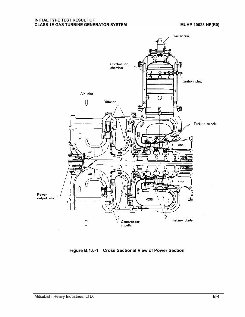
Figure B.1.0-1 Cross Sectional View of Power Section
INITIAL TYPE TEST RESULT OF CLASS 1E GAS TURBINE GENERATOR SYSTEM MUAP-10023-NP(R0)
Mitsubishi Heavy Industries, LTD. B-5
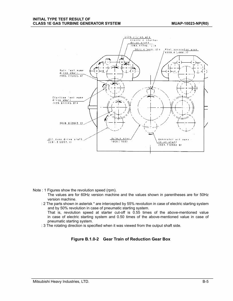
Note : 1 Figures show the revolution speed (rpm). The values are for 60Hz version machine and the values shown in parentheses are for 50Hz
version machine. : 2 The parts shown in asterisk * are intercepted by 55% revolution in case of electric starting system
and by 50% revolution in case of pneumatic starting system. That is, revolution speed at starter cut-off is 0.55 times of the above-mentioned value
in case of electric starting system and 0.50 times of the above-mentioned value in case of pneumatic starting system.
: 3 The rotating direction is specified when it was viewed from the output shaft side.
Figure B.1.0-2 Gear Train of Reduction Gear Box
*
* *
*

INITIAL TYPE TEST RESULT OF CLASS 1E GAS TURBINE GENERATOR SYSTEM MUAP-10023-NP(R0)
Mitsubishi Heavy Industries, LTD. B-6
Fig
ure
B.1
.0-3
In
stal
lati
on
Dra
win
g o
f G
as T
urb
ine
Ass
emb
ly (
Sh
eet
1 o
f 6)
Mitsubishi Heavy Industries, LTD. B-7
INITIAL TYPE TEST RESULT OF CLASS 1E GAS TURBINE GENERATOR SYSTEM MUAP-10023-NP(R0)
Fig
ure
B.1
.0-3
In
stal
lati
on
Dra
win
g o
f G
as T
urb
ine
Ass
emb
ly (
Sh
eet
2 o
f 6)
Mitsubishi Heavy Industries, LTD. B-8
INITIAL TYPE TEST RESULT OF CLASS 1E GAS TURBINE GENERATOR SYSTEM MUAP-10023-NP(R0)
Fig
ure
B.1
.0-3
In
stal
lati
on
Dra
win
g o
f G
as T
urb
ine
Ass
emb
ly (
Sh
eet
3 o
f 6)

INITIAL TYPE TEST RESULT OF CLASS 1E GAS TURBINE GENERATOR SYSTEM MUAP-10023-NP(R0)
Mitsubishi Heavy Industries, LTD. B-9
F
igu
re B
.1.0
-3
Inst
alla
tio
n D
raw
ing
of
Gas
Tu
rbin
e A
ssem
bly
(S
he
et 4
of
6)

Mitsubishi Heavy Industries, LTD. B-10
INITIAL TYPE TEST RESULT OF CLASS 1E GAS TURBINE GENERATOR SYSTEM MUAP-10023-NP(R0)
F
igu
re B
.1.0
-3
Inst
alla
tio
n D
raw
ing
of
Gas
Tu
rbin
e A
ssem
bly
(S
he
et 5
of
6)

Mitsubishi Heavy Industries, LTD. B-11
INITIAL TYPE TEST RESULT OF CLASS 1E GAS TURBINE GENERATOR SYSTEM MUAP-10023-NP(R0)
F
igu
re B
.1.0
-3
Inst
alla
tio
n D
raw
ing
of
Gas
Tu
rbin
e A
ssem
bly
(S
he
et 6
of
6)

Mitsubishi Heavy Industries, LTD. B-12
INITIAL TYPE TEST RESULT OF CLASS 1E GAS TURBINE GENERATOR SYSTEM MUAP-10023-NP(R0)
F
igu
re B
.1.0
-4
Dra
win
g o
f F
uel
Da
y Ta
nk
(Sh
eet
1 o
f 2)

Mitsubishi Heavy Industries, LTD. B-13
INITIAL TYPE TEST RESULT OF CLASS 1E GAS TURBINE GENERATOR SYSTEM MUAP-10023-NP(R0)
F
igu
re B
.1.0
-4
Dra
win
g o
f F
uel
Da
y Ta
nk
(Sh
eet
2 o
f 2)
Mitsubishi Heavy Industries, LTD. B-14
INITIAL TYPE TEST RESULT OF CLASS 1E GAS TURBINE GENERATOR SYSTEM MUAP-10023-NP(R0)
F
igu
re B
.1.0
-5
Dra
win
g o
f A
ir R
ecei
ver
(Sh
eet
1 o
f 3)

Mitsubishi Heavy Industries, LTD. B-15
INITIAL TYPE TEST RESULT OF CLASS 1E GAS TURBINE GENERATOR SYSTEM MUAP-10023-NP(R0)
F
igu
re B
.1.0
-5
Dra
win
g o
f A
ir R
ecei
ver
(Sh
eet
2 o
f 3)
Mitsubishi Heavy Industries, LTD. B-16
INITIAL TYPE TEST RESULT OF CLASS 1E GAS TURBINE GENERATOR SYSTEM MUAP-10023-NP(R0)
F
igu
re B
.1.0
-5
Dra
win
g o
f A
ir R
ecei
ver
(Sh
eet
3 o
f 3)

Mitsubishi Heavy Industries, LTD. B-17
INITIAL TYPE TEST RESULT OF CLASS 1E GAS TURBINE GENERATOR SYSTEM MUAP-10023-NP(R0)
F
igu
re B
.1.0
-6
Dra
win
g o
f E
ncl
osu
re a
nd
Ski
d (
Sh
eet
1 o
f 3)
Mitsubishi Heavy Industries, LTD. B-18
INITIAL TYPE TEST RESULT OF CLASS 1E GAS TURBINE GENERATOR SYSTEM MUAP-10023-NP(R0)
F
igu
re B
.1.0
-6
Dra
win
g o
f E
ncl
osu
re a
nd
Ski
d (
Sh
eet
2 o
f 3)

Mitsubishi Heavy Industries, LTD. B-19
INITIAL TYPE TEST RESULT OF CLASS 1E GAS TURBINE GENERATOR SYSTEM MUAP-10023-NP(R0)
F
igu
re B
.1.0
-6
Dra
win
g o
f E
ncl
osu
re a
nd
Ski
d (
Sh
eet
3 o
f 3)
Mitsubishi Heavy Industries, LTD. B-20
INITIAL TYPE TEST RESULT OF CLASS 1E GAS TURBINE GENERATOR SYSTEM MUAP-10023-NP(R0)
F
igu
re B
.1.0
-7
Co
nfi
gu
rati
on
of
Lu
bri
can
t O
il S
yste
m (
Sh
eet
1 o
f 2)
Mitsubishi Heavy Industries, LTD. B-21
INITIAL TYPE TEST RESULT OF CLASS 1E GAS TURBINE GENERATOR SYSTEM MUAP-10023-NP(R0)
F
igu
re B
.1.0
-7
Co
nfi
gu
rati
on
of
Lu
bri
can
t O
il S
yste
m (
Sh
eet
2 o
f 2)

Mitsubishi Heavy Industries, LTD. B-22
INITIAL TYPE TEST RESULT OF CLASS 1E GAS TURBINE GENERATOR SYSTEM MUAP-10023-NP(R0)
F
igu
re B
.1.0
-8
Co
nfi
gu
rati
on
of
Fu
el O
il S
yste
m
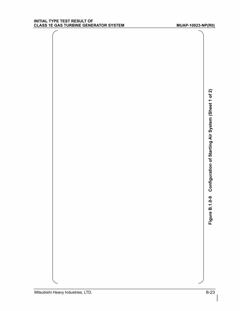
Mitsubishi Heavy Industries, LTD. B-23
INITIAL TYPE TEST RESULT OF CLASS 1E GAS TURBINE GENERATOR SYSTEM MUAP-10023-NP(R0)
F
igu
re B
.1.0
-9
Co
nfi
gu
rati
on
of
Sta
rtin
g A
ir S
yste
m (
Sh
eet
1 o
f 2)

Mitsubishi Heavy Industries, LTD. B-24
INITIAL TYPE TEST RESULT OF CLASS 1E GAS TURBINE GENERATOR SYSTEM MUAP-10023-NP(R0)
F
igu
re B
.1.0
-9
Co
nfi
gu
rati
on
of
Sta
rtin
g A
ir S
yste
m (
Sh
eet
2 o
f 2)
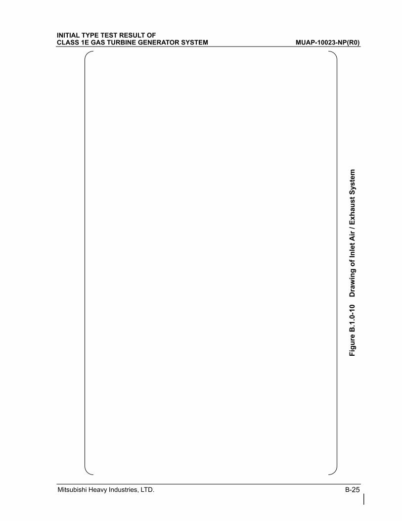
Mitsubishi Heavy Industries, LTD. B-25
INITIAL TYPE TEST RESULT OF CLASS 1E GAS TURBINE GENERATOR SYSTEM MUAP-10023-NP(R0)
F
igu
re B
.1.0
-10
Dra
win
g o
f In
let
Air
/ E
xhau
st S
yste
m
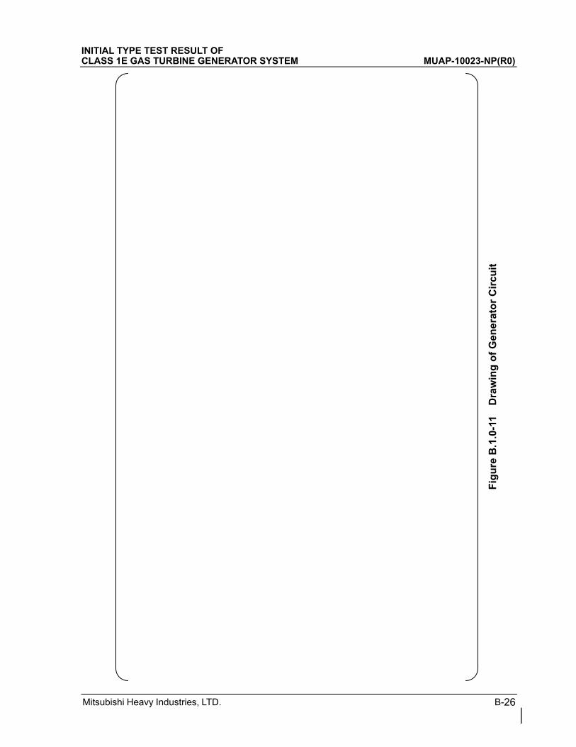
Mitsubishi Heavy Industries, LTD. B-26
INITIAL TYPE TEST RESULT OF CLASS 1E GAS TURBINE GENERATOR SYSTEM MUAP-10023-NP(R0)
F
igu
re B
.1.0
-11
Dra
win
g o
f G
ener
ato
r C
ircu
it
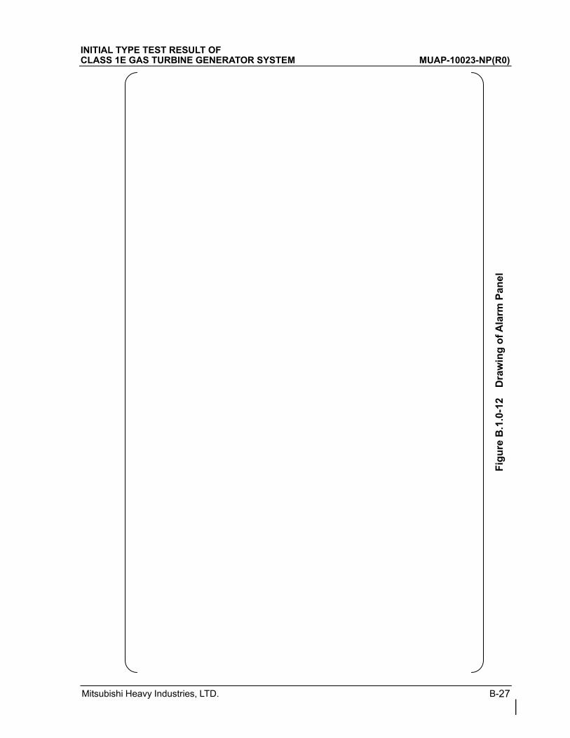
Mitsubishi Heavy Industries, LTD. B-27
INITIAL TYPE TEST RESULT OF CLASS 1E GAS TURBINE GENERATOR SYSTEM MUAP-10023-NP(R0)
F
igu
re B
.1.0
-12
Dra
win
g o
f A
larm
Pan
el
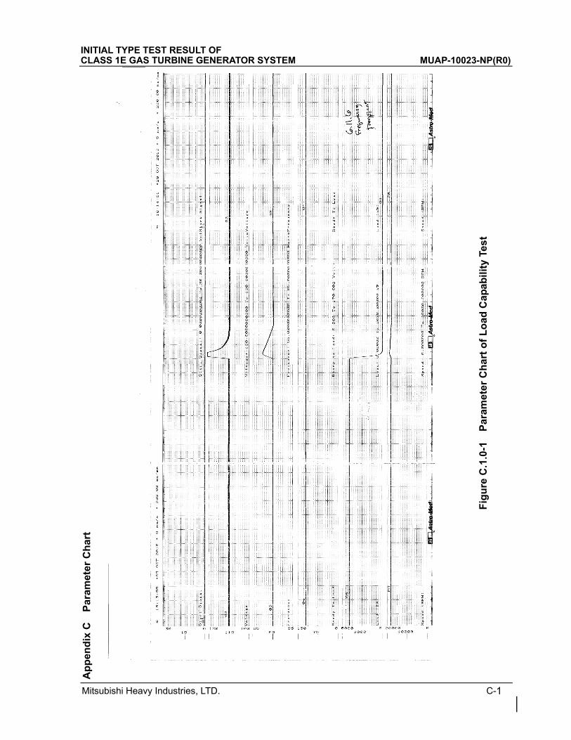
INITIAL TYPE TEST RESULT OF CLASS 1E GAS TURBINE GENERATOR SYSTEM MUAP-10023-NP(R0)
Mitsubishi Heavy Industries, LTD. C-1
Ap
pen
dix
C
Par
amet
er
Ch
art
F
igu
re C
.1.0
-1
Par
amet
er C
har
t o
f L
oad
Cap
abili
ty T
est
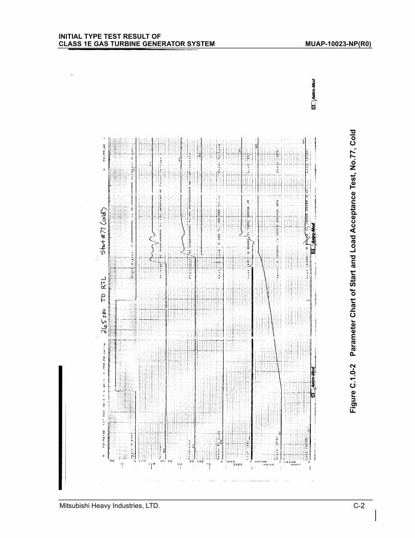
Mitsubishi Heavy Industries, LTD. C-2
INITIAL TYPE TEST RESULT OF CLASS 1E GAS TURBINE GENERATOR SYSTEM MUAP-10023-NP(R0)
Fig
ure
C.1
.0-2
P
aram
eter
Ch
art
of
Sta
rt a
nd
Lo
ad A
ccep
tan
ce T
est,
No
.77,
Co
ld
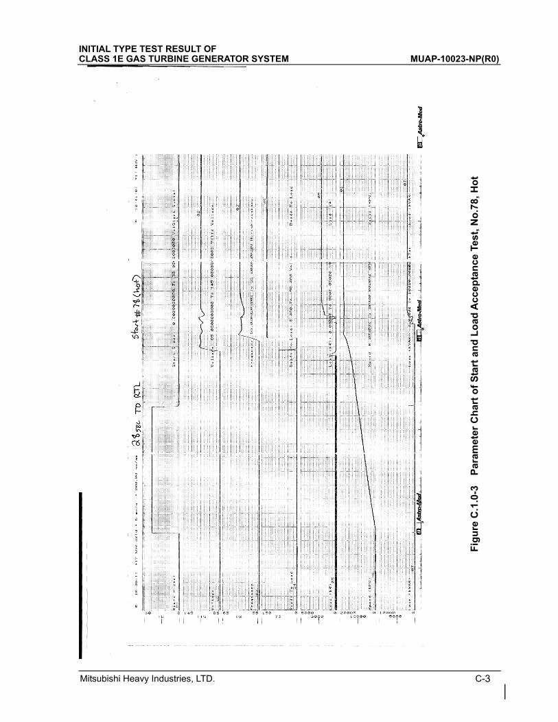
Mitsubishi Heavy Industries, LTD. C-3
INITIAL TYPE TEST RESULT OF CLASS 1E GAS TURBINE GENERATOR SYSTEM MUAP-10023-NP(R0)
Fig
ure
C.1
.0-3
P
aram
eter
Ch
art
of
Sta
rt a
nd
Lo
ad A
ccep
tan
ce T
est,
No
.78,
Ho
t
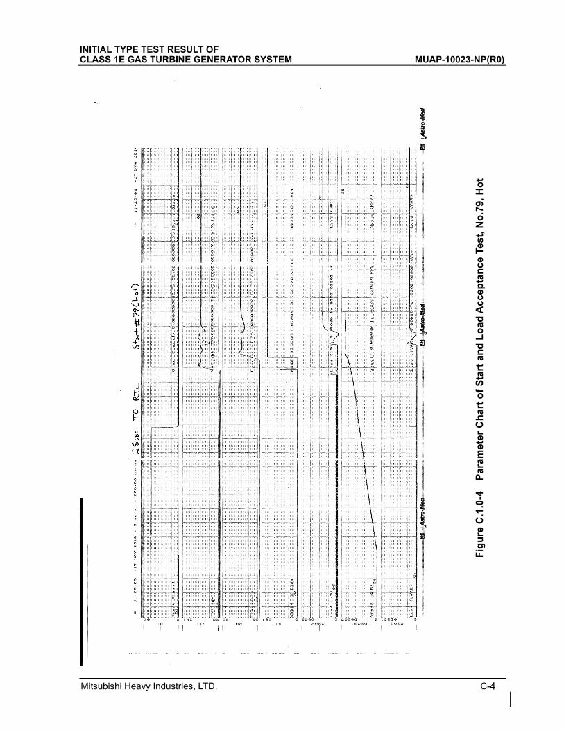
Mitsubishi Heavy Industries, LTD. C-4
INITIAL TYPE TEST RESULT OF CLASS 1E GAS TURBINE GENERATOR SYSTEM MUAP-10023-NP(R0)
Fig
ure
C.1
.0-4
P
aram
eter
Ch
art
of
Sta
rt a
nd
Lo
ad A
ccep
tan
ce T
est,
No
.79,
Ho
t
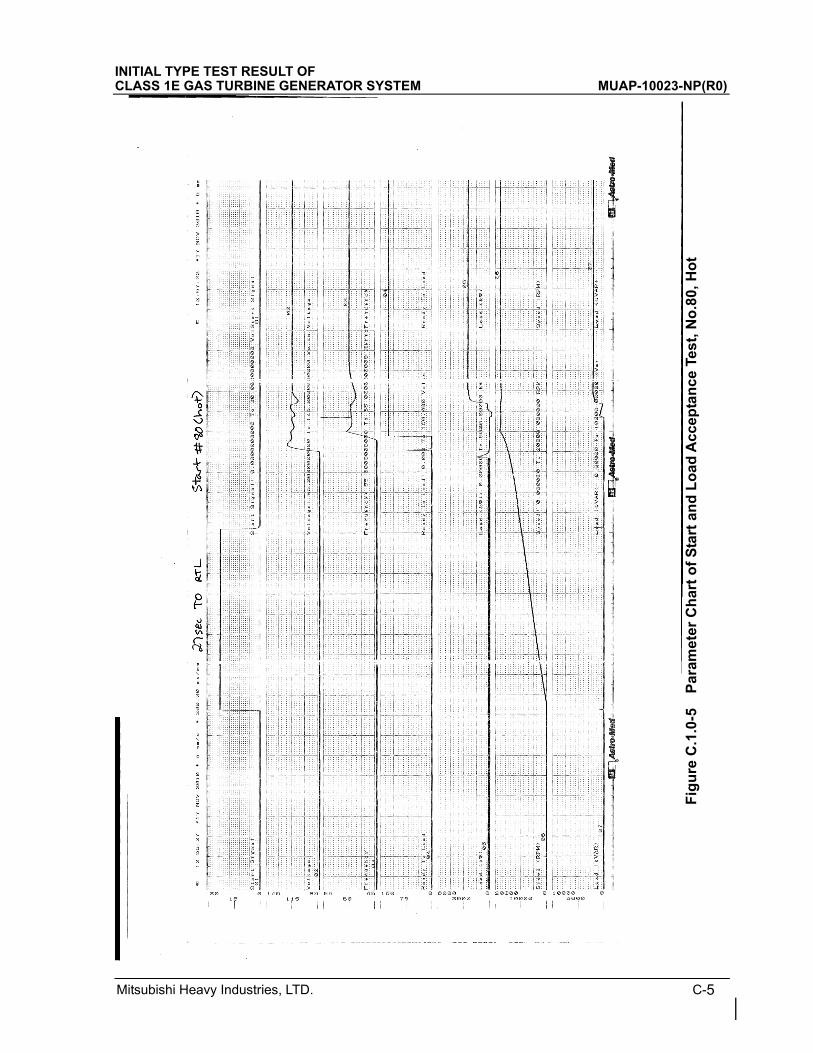
Mitsubishi Heavy Industries, LTD. C-5
INITIAL TYPE TEST RESULT OF CLASS 1E GAS TURBINE GENERATOR SYSTEM MUAP-10023-NP(R0)
Fig
ure
C.1
.0-5
P
aram
eter
Ch
art
of
Sta
rt a
nd
Lo
ad A
ccep
tan
ce T
est,
No
.80,
Ho
t
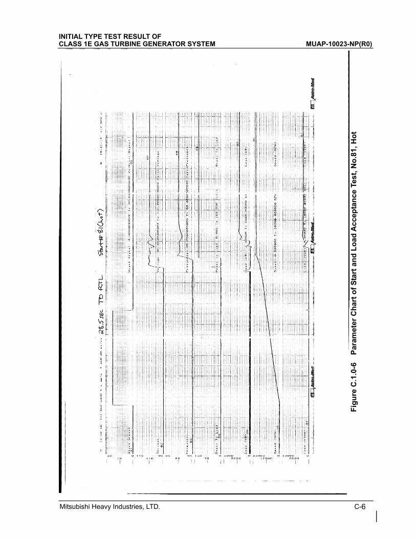
Mitsubishi Heavy Industries, LTD. C-6
INITIAL TYPE TEST RESULT OF CLASS 1E GAS TURBINE GENERATOR SYSTEM MUAP-10023-NP(R0)
Fig
ure
C.1
.0-6
P
aram
eter
Ch
art
of
Sta
rt a
nd
Lo
ad A
ccep
tan
ce T
est,
No
.81,
Ho
t
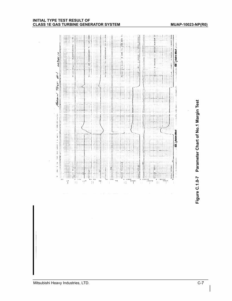
Mitsubishi Heavy Industries, LTD. C-7
INITIAL TYPE TEST RESULT OF CLASS 1E GAS TURBINE GENERATOR SYSTEM MUAP-10023-NP(R0)
Fig
ure
C.1
.0-7
P
aram
eter
Ch
art
of
No
.1 M
arg
in T
est
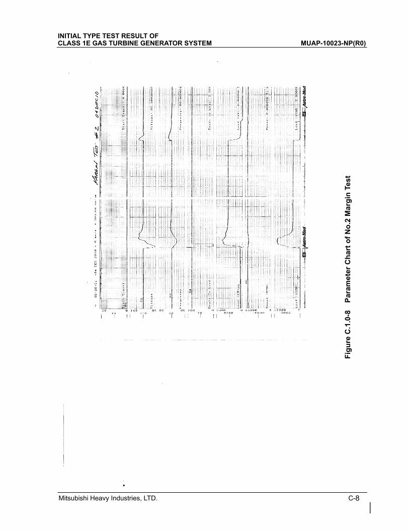
Mitsubishi Heavy Industries, LTD. C-8
INITIAL TYPE TEST RESULT OF CLASS 1E GAS TURBINE GENERATOR SYSTEM MUAP-10023-NP(R0)
Fig
ure
C.1
.0-8
P
aram
eter
Ch
art
of
No
.2 M
arg
in T
est
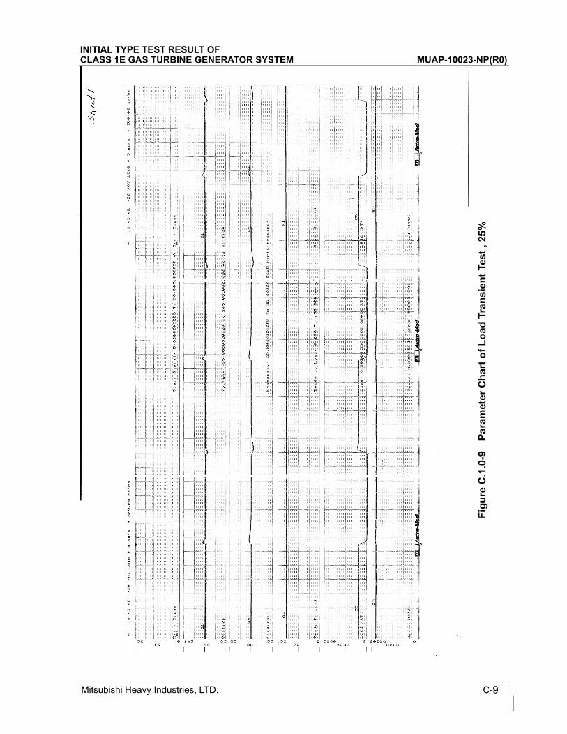
Mitsubishi Heavy Industries, LTD. C-9
INITIAL TYPE TEST RESULT OF CLASS 1E GAS TURBINE GENERATOR SYSTEM MUAP-10023-NP(R0)
Fig
ure
C.1
.0-9
P
aram
eter
Ch
art
of
Lo
ad T
ran
sien
t Te
st ,
25%
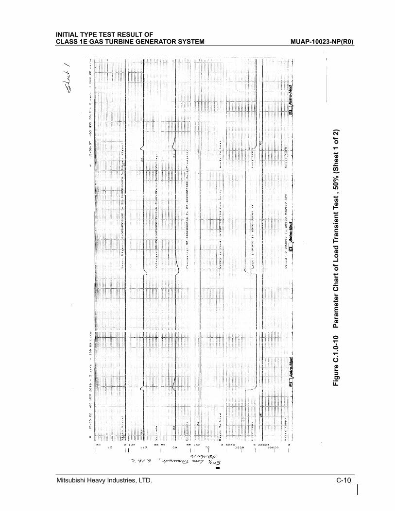
Mitsubishi Heavy Industries, LTD. C-10
INITIAL TYPE TEST RESULT OF CLASS 1E GAS TURBINE GENERATOR SYSTEM MUAP-10023-NP(R0)
Fig
ure
C.1
.0-1
0 P
aram
eter
Ch
art
of
Lo
ad T
ran
sien
t Te
st ,
50%
(S
hee
t 1
of
2)
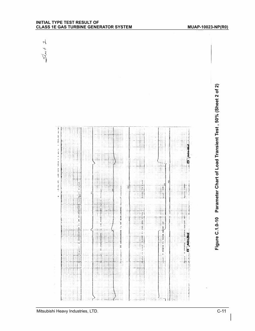
Mitsubishi Heavy Industries, LTD. C-11
INITIAL TYPE TEST RESULT OF CLASS 1E GAS TURBINE GENERATOR SYSTEM MUAP-10023-NP(R0)
Fig
ure
C.1
.0-1
0 P
aram
eter
Ch
art
of
Lo
ad T
ran
sien
t Te
st ,
50%
(S
hee
t 2
of
2)
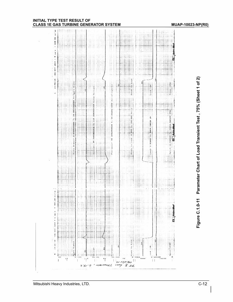
Mitsubishi Heavy Industries, LTD. C-12
INITIAL TYPE TEST RESULT OF CLASS 1E GAS TURBINE GENERATOR SYSTEM MUAP-10023-NP(R0)
Fig
ure
C.1
.0-1
1 P
aram
eter
Ch
art
of
Lo
ad T
ran
sien
t Te
st ,
75%
(S
hee
t 1
of
2)
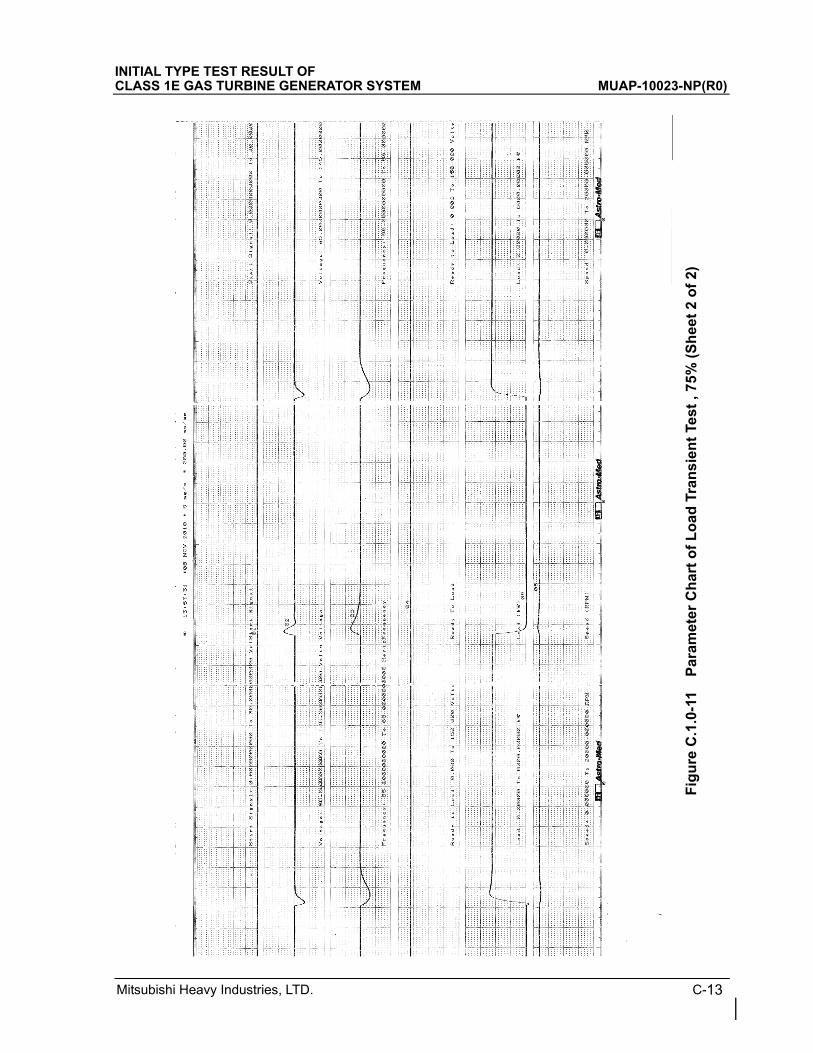
Mitsubishi Heavy Industries, LTD. C-13
INITIAL TYPE TEST RESULT OF CLASS 1E GAS TURBINE GENERATOR SYSTEM MUAP-10023-NP(R0)
Fig
ure
C.1
.0-1
1 P
aram
eter
Ch
art
of
Lo
ad T
ran
sien
t Te
st ,
75%
(S
hee
t 2
of
2)
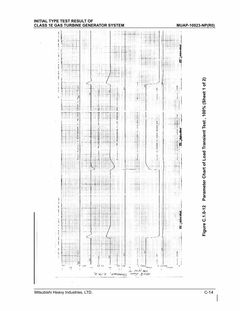
Mitsubishi Heavy Industries, LTD. C-14
INITIAL TYPE TEST RESULT OF CLASS 1E GAS TURBINE GENERATOR SYSTEM MUAP-10023-NP(R0)
Fig
ure
C.1
.0-1
2 P
aram
eter
Ch
art
of
Lo
ad T
ran
sien
t Te
st ,
100
% (
Sh
eet
1 o
f 2)
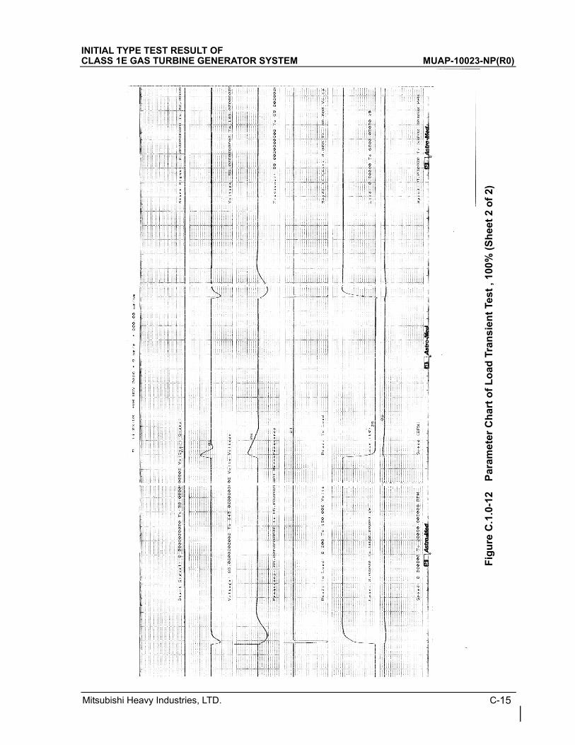
Mitsubishi Heavy Industries, LTD. C-15
INITIAL TYPE TEST RESULT OF CLASS 1E GAS TURBINE GENERATOR SYSTEM MUAP-10023-NP(R0)
Fig
ure
C.1
.0-1
2 P
aram
eter
Ch
art
of
Lo
ad T
ran
sien
t Te
st ,
100
% (
Sh
eet
2 o
f 2)
INITIAL TYPE TEST RESULT OF CLASS 1E GAS TURBINE GENERATOR SYSTEM MUAP-10023-NP(R0)
Mitsubishi Heavy Industries, LTD. D-1
Appendix D Initial Type Test Procedure

INITIAL TYPE TEST RESULT OF CLASS 1E GAS TURBINE GENERATOR SYSTEM MUAP-10023-NP(R0)
Mitsubishi Heavy Industries, LTD. D-2

INITIAL TYPE TEST RESULT OF CLASS 1E GAS TURBINE GENERATOR SYSTEM MUAP-10023-NP(R0)
Mitsubishi Heavy Industries, LTD. D-3

INITIAL TYPE TEST RESULT OF CLASS 1E GAS TURBINE GENERATOR SYSTEM MUAP-10023-NP(R0)
Mitsubishi Heavy Industries, LTD. D-4

INITIAL TYPE TEST RESULT OF CLASS 1E GAS TURBINE GENERATOR SYSTEM MUAP-10023-NP(R0)
Mitsubishi Heavy Industries, LTD. D-5

INITIAL TYPE TEST RESULT OF CLASS 1E GAS TURBINE GENERATOR SYSTEM MUAP-10023-NP(R0)
Mitsubishi Heavy Industries, LTD. D-6

INITIAL TYPE TEST RESULT OF CLASS 1E GAS TURBINE GENERATOR SYSTEM MUAP-10023-NP(R0)
Mitsubishi Heavy Industries, LTD. D-7

INITIAL TYPE TEST RESULT OF CLASS 1E GAS TURBINE GENERATOR SYSTEM MUAP-10023-NP(R0)
Mitsubishi Heavy Industries, LTD. D-8

INITIAL TYPE TEST RESULT OF CLASS 1E GAS TURBINE GENERATOR SYSTEM MUAP-10023-NP(R0)
Mitsubishi Heavy Industries, LTD. D-9
INITIAL TYPE TEST RESULT OF CLASS 1E GAS TURBINE GENERATOR SYSTEM MUAP-10023-NP(R0)
Mitsubishi Heavy Industries, LTD. D-10

INITIAL TYPE TEST RESULT OF CLASS 1E GAS TURBINE GENERATOR SYSTEM MUAP-10023-NP(R0)
Mitsubishi Heavy Industries, LTD. D-11

INITIAL TYPE TEST RESULT OF CLASS 1E GAS TURBINE GENERATOR SYSTEM MUAP-10023-NP(R0)
Mitsubishi Heavy Industries, LTD. D-12

INITIAL TYPE TEST RESULT OF CLASS 1E GAS TURBINE GENERATOR SYSTEM MUAP-10023-NP(R0)
Mitsubishi Heavy Industries, LTD. D-13

INITIAL TYPE TEST RESULT OF CLASS 1E GAS TURBINE GENERATOR SYSTEM MUAP-10023-NP(R0)
Mitsubishi Heavy Industries, LTD. D-14

INITIAL TYPE TEST RESULT OF CLASS 1E GAS TURBINE GENERATOR SYSTEM MUAP-10023-NP(R0)
Mitsubishi Heavy Industries, LTD. D-15

INITIAL TYPE TEST RESULT OF CLASS 1E GAS TURBINE GENERATOR SYSTEM MUAP-10023-NP(R0)
Mitsubishi Heavy Industries, LTD. D-16

INITIAL TYPE TEST RESULT OF CLASS 1E GAS TURBINE GENERATOR SYSTEM MUAP-10023-NP(R0)
Mitsubishi Heavy Industries, LTD. D-17

INITIAL TYPE TEST RESULT OF CLASS 1E GAS TURBINE GENERATOR SYSTEM MUAP-10023-NP(R0)
Mitsubishi Heavy Industries, LTD. D-18

INITIAL TYPE TEST RESULT OF CLASS 1E GAS TURBINE GENERATOR SYSTEM MUAP-10023-NP(R0)
Mitsubishi Heavy Industries, LTD. D-19

INITIAL TYPE TEST RESULT OF CLASS 1E GAS TURBINE GENERATOR SYSTEM MUAP-10023-NP(R0)
Mitsubishi Heavy Industries, LTD. D-20

INITIAL TYPE TEST RESULT OF CLASS 1E GAS TURBINE GENERATOR SYSTEM MUAP-10023-NP(R0)
Mitsubishi Heavy Industries, LTD. D-21

INITIAL TYPE TEST RESULT OF CLASS 1E GAS TURBINE GENERATOR SYSTEM MUAP-10023-NP(R0)
Mitsubishi Heavy Industries, LTD. D-22

INITIAL TYPE TEST RESULT OF CLASS 1E GAS TURBINE GENERATOR SYSTEM MUAP-10023-NP(R0)
Mitsubishi Heavy Industries, LTD. D-23

INITIAL TYPE TEST RESULT OF CLASS 1E GAS TURBINE GENERATOR SYSTEM MUAP-10023-NP(R0)
Mitsubishi Heavy Industries, LTD. D-24

INITIAL TYPE TEST RESULT OF CLASS 1E GAS TURBINE GENERATOR SYSTEM MUAP-10023-NP(R0)
Mitsubishi Heavy Industries, LTD. D-25

INITIAL TYPE TEST RESULT OF CLASS 1E GAS TURBINE GENERATOR SYSTEM MUAP-10023-NP(R0)
Mitsubishi Heavy Industries, LTD. D-26

INITIAL TYPE TEST RESULT OF CLASS 1E GAS TURBINE GENERATOR SYSTEM MUAP-10023-NP(R0)
Mitsubishi Heavy Industries, LTD. D-27
INITIAL TYPE TEST RESULT OF CLASS 1E GAS TURBINE GENERATOR SYSTEM MUAP-10023-NP(R0)
Mitsubishi Heavy Industries, LTD. D-28

INITIAL TYPE TEST RESULT OF CLASS 1E GAS TURBINE GENERATOR SYSTEM MUAP-10023-NP(R0)
Mitsubishi Heavy Industries, LTD. D-29

INITIAL TYPE TEST RESULT OF CLASS 1E GAS TURBINE GENERATOR SYSTEM MUAP-10023-NP(R0)
Mitsubishi Heavy Industries, LTD. D-30

INITIAL TYPE TEST RESULT OF CLASS 1E GAS TURBINE GENERATOR SYSTEM MUAP-10023-NP(R0)
Mitsubishi Heavy Industries, LTD. D-31

INITIAL TYPE TEST RESULT OF CLASS 1E GAS TURBINE GENERATOR SYSTEM MUAP-10023-NP(R0)
Mitsubishi Heavy Industries, LTD. D-32

INITIAL TYPE TEST RESULT OF CLASS 1E GAS TURBINE GENERATOR SYSTEM MUAP-10023-NP(R0)
Mitsubishi Heavy Industries, LTD. D-33

INITIAL TYPE TEST RESULT OF CLASS 1E GAS TURBINE GENERATOR SYSTEM MUAP-10023-NP(R0)
Mitsubishi Heavy Industries, LTD. D-34

INITIAL TYPE TEST RESULT OF CLASS 1E GAS TURBINE GENERATOR SYSTEM MUAP-10023-NP(R0)
Mitsubishi Heavy Industries, LTD. D-35

INITIAL TYPE TEST RESULT OF CLASS 1E GAS TURBINE GENERATOR SYSTEM MUAP-10023-NP(R0)
Mitsubishi Heavy Industries, LTD. D-36

INITIAL TYPE TEST RESULT OF CLASS 1E GAS TURBINE GENERATOR SYSTEM MUAP-10023-NP(R0)
Mitsubishi Heavy Industries, LTD. D-37

INITIAL TYPE TEST RESULT OF CLASS 1E GAS TURBINE GENERATOR SYSTEM MUAP-10023-NP(R0)
Mitsubishi Heavy Industries, LTD. D-38

INITIAL TYPE TEST RESULT OF CLASS 1E GAS TURBINE GENERATOR SYSTEM MUAP-10023-NP(R0)
Mitsubishi Heavy Industries, LTD. D-39

INITIAL TYPE TEST RESULT OF CLASS 1E GAS TURBINE GENERATOR SYSTEM MUAP-10023-NP(R0)
Mitsubishi Heavy Industries, LTD. D-40

INITIAL TYPE TEST RESULT OF CLASS 1E GAS TURBINE GENERATOR SYSTEM MUAP-10023-NP(R0)
Mitsubishi Heavy Industries, LTD. D-41

INITIAL TYPE TEST RESULT OF CLASS 1E GAS TURBINE GENERATOR SYSTEM MUAP-10023-NP(R0)
Mitsubishi Heavy Industries, LTD. D-42

INITIAL TYPE TEST RESULT OF CLASS 1E GAS TURBINE GENERATOR SYSTEM MUAP-10023-NP(R0)
Mitsubishi Heavy Industries, LTD. D-43

INITIAL TYPE TEST RESULT OF CLASS 1E GAS TURBINE GENERATOR SYSTEM MUAP-10023-NP(R0)
Mitsubishi Heavy Industries, LTD. D-44

INITIAL TYPE TEST RESULT OF CLASS 1E GAS TURBINE GENERATOR SYSTEM MUAP-10023-NP(R0)
Mitsubishi Heavy Industries, LTD. D-45

INITIAL TYPE TEST RESULT OF CLASS 1E GAS TURBINE GENERATOR SYSTEM MUAP-10023-NP(R0)
Mitsubishi Heavy Industries, LTD. D-46

INITIAL TYPE TEST RESULT OF CLASS 1E GAS TURBINE GENERATOR SYSTEM MUAP-10023-NP(R0)
Mitsubishi Heavy Industries, LTD. D-47

INITIAL TYPE TEST RESULT OF CLASS 1E GAS TURBINE GENERATOR SYSTEM MUAP-10023-NP(R0)
Mitsubishi Heavy Industries, LTD. D-48

INITIAL TYPE TEST RESULT OF CLASS 1E GAS TURBINE GENERATOR SYSTEM MUAP-10023-NP(R0)
Mitsubishi Heavy Industries, LTD. D-49

INITIAL TYPE TEST RESULT OF CLASS 1E GAS TURBINE GENERATOR SYSTEM MUAP-10023-NP(R0)
Mitsubishi Heavy Industries, LTD. D-50

INITIAL TYPE TEST RESULT OF CLASS 1E GAS TURBINE GENERATOR SYSTEM MUAP-10023-NP(R0)
Mitsubishi Heavy Industries, LTD. D-51

INITIAL TYPE TEST RESULT OF CLASS 1E GAS TURBINE GENERATOR SYSTEM MUAP-10023-NP(R0)
Mitsubishi Heavy Industries, LTD. D-52

INITIAL TYPE TEST RESULT OF CLASS 1E GAS TURBINE GENERATOR SYSTEM MUAP-10023-NP(R0)
Mitsubishi Heavy Industries, LTD. D-53

INITIAL TYPE TEST RESULT OF CLASS 1E GAS TURBINE GENERATOR SYSTEM MUAP-10023-NP(R0)
Mitsubishi Heavy Industries, LTD. D-54

INITIAL TYPE TEST RESULT OF CLASS 1E GAS TURBINE GENERATOR SYSTEM MUAP-10023-NP(R0)
Mitsubishi Heavy Industries, LTD. D-55


![AIR EXHAUST AIR INTAKE AIR EXHAUST - Excelitas...P. CONSTANTINOU M. KAY 02/23/2016 02/24/2016 02/24/2016 (DIMENSIONS IN [ ] ARE INCHES) 2260 ARGENTIA ROAD, MISSISSAUGA, ONTARIO, L5N](https://img.pdfslide.us/doc/110x75/5ee0448cad6a402d666b7bbe/air-exhaust-air-intake-air-exhaust-excelitas-p-constantinou-m-kay-02232016.jpg)


![[PPT]Intake and Exhaust Systems/ Turbochargers and · Web viewIntake and Exhaust Systems/ Turbochargers and Superchargers Chapter 42 Objectives Explain the operation of the air intake](https://img.pdfslide.us/doc/110x75/5ab393037f8b9a7e1d8e50c6/pptintake-and-exhaust-systems-turbochargers-and-viewintake-and-exhaust-systems.jpg)