Embed Size (px)
Citation preview
15-1
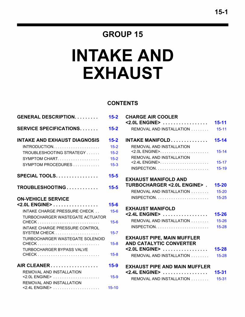
GROUP 15
INTAKE AND EXHAUST
CONTENTS
GENERAL DESCRIPTION. . . . . . . . . 15-2
SERVICE SPECIFICATIONS. . . . . . . 15-2
INTAKE AND EXHAUST DIAGNOSIS 15-2INTRODUCTION. . . . . . . . . . . . . . . . . . . . . 15-2TROUBLESHOOTING STRATEGY . . . . . . 15-2SYMPTOM CHART. . . . . . . . . . . . . . . . . . . 15-2SYMPTOM PROCEDURES . . . . . . . . . . . . 15-3
SPECIAL TOOLS. . . . . . . . . . . . . . . . 15-5
TROUBLESHOOTING . . . . . . . . . . . . 15-5
ON-VEHICLE SERVICE <2.0L ENGINE> . . . . . . . . . . . . . . . . . 15-6
INTAKE CHARGE PRESSURE CHECK . . 15-6TURBOCHARGER WASTEGATE ACTUATOR CHECK . . . . . . . . . . . . . . . . . . . . . . . . . . . . 15-6INTAKE CHARGE PRESSURE CONTROL SYSTEM CHECK . . . . . . . . . . . . . . . . . . . . 15-7TURBOCHARGER WASTEGATE SOLENOID CHECK . . . . . . . . . . . . . . . . . . . . . . . . . . . . 15-8TURBOCHARGER BYPASS VALVE CHECK . . . . . . . . . . . . . . . . . . . . . . . . . . . . 15-8
AIR CLEANER . . . . . . . . . . . . . . . . . . 15-9REMOVAL AND INSTALLATION <2.0L ENGINE> . . . . . . . . . . . . . . . . . . . . . 15-9REMOVAL AND INSTALLATION <2.4L ENGINE> . . . . . . . . . . . . . . . . . . . . . 15-10
CHARGE AIR COOLER <2.0L ENGINE> . . . . . . . . . . . . . . . . . 15-11
REMOVAL AND INSTALLATION . . . . . . . . 15-11
INTAKE MANIFOLD . . . . . . . . . . . . . . 15-14REMOVAL AND INSTALLATION <2.0L ENGINE>. . . . . . . . . . . . . . . . . . . . . . 15-14REMOVAL AND INSTALLATION <2.4L ENGINE>. . . . . . . . . . . . . . . . . . . . . . 15-17INSPECTION. . . . . . . . . . . . . . . . . . . . . . . . 15-19
EXHAUST MANIFOLD AND TURBOCHARGER <2.0L ENGINE> . 15-20
REMOVAL AND INSTALLATION . . . . . . . . 15-20INSPECTION. . . . . . . . . . . . . . . . . . . . . . . . 15-25
EXHAUST MANIFOLD <2.4L ENGINE> . . . . . . . . . . . . . . . . . 15-26
REMOVAL AND INSTALLATION . . . . . . . . 15-26INSPECTION. . . . . . . . . . . . . . . . . . . . . . . . 15-28
EXHAUST PIPE, MAIN MUFFLER AND CATALYTIC CONVERTER <2.0L ENGINE> . . . . . . . . . . . . . . . . . 15-28
REMOVAL AND INSTALLATION . . . . . . . . 15-28
EXHAUST PIPE AND MAIN MUFFLER <2.4L ENGINE> . . . . . . . . . . . . . . . . . 15-31
REMOVAL AND INSTALLATION . . . . . . . . 15-31
GENERAL DESCRIPTIONINTAKE AND EXHAUST15-2
GENERAL DESCRIPTIONM1151000101386
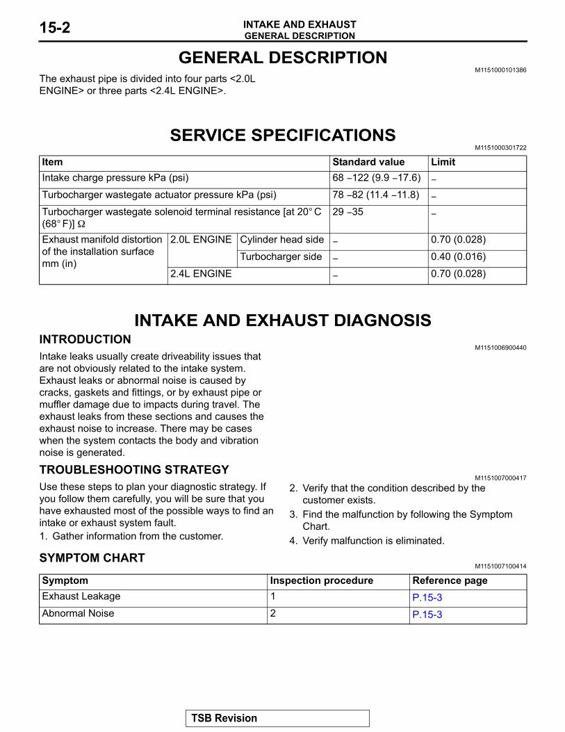
The exhaust pipe is divided into four parts <2.0L ENGINE> or three parts <2.4L ENGINE>.
SERVICE SPECIFICATIONSM1151000301722
INTAKE AND EXHAUST DIAGNOSISINTRODUCTION
M1151006900440Intake leaks usually create driveability issues that are not obviously related to the intake system. Exhaust leaks or abnormal noise is caused by cracks, gaskets and fittings, or by exhaust pipe or muffler damage due to impacts during travel. The exhaust leaks from these sections and causes the exhaust noise to increase. There may be cases when the system contacts the body and vibration noise is generated.
TROUBLESHOOTING STRATEGYM1151007000417
Use these steps to plan your diagnostic strategy. If you follow them carefully, you will be sure that you have exhausted most of the possible ways to find an intake or exhaust system fault.1. Gather information from the customer.
2. Verify that the condition described by the customer exists.
3. Find the malfunction by following the Symptom Chart.
4. Verify malfunction is eliminated.
SYMPTOM CHARTM1151007100414
Item Standard value LimitIntake charge pressure kPa (psi) 68 − 122 (9.9 − 17.6) −
Turbocharger wastegate actuator pressure kPa (psi) 78 − 82 (11.4 − 11.8) −
Turbocharger wastegate solenoid terminal resistance [at 20° C (68° F)] Ω
29 − 35 −
Exhaust manifold distortion of the installation surface mm (in)
2.0L ENGINE Cylinder head side − 0.70 (0.028)
Turbocharger side − 0.40 (0.016)
2.4L ENGINE − 0.70 (0.028)
Symptom Inspection procedure Reference pageExhaust Leakage 1 P.15-3Abnormal Noise 2 P.15-3
TSB Revision
INTAKE AND EXHAUST DIAGNOSISINTAKE AND EXHAUST 15-3
SYMPTOM PROCEDURES
Inspection Procedure 1: Exhaust Leakage
DIAGNOSIS
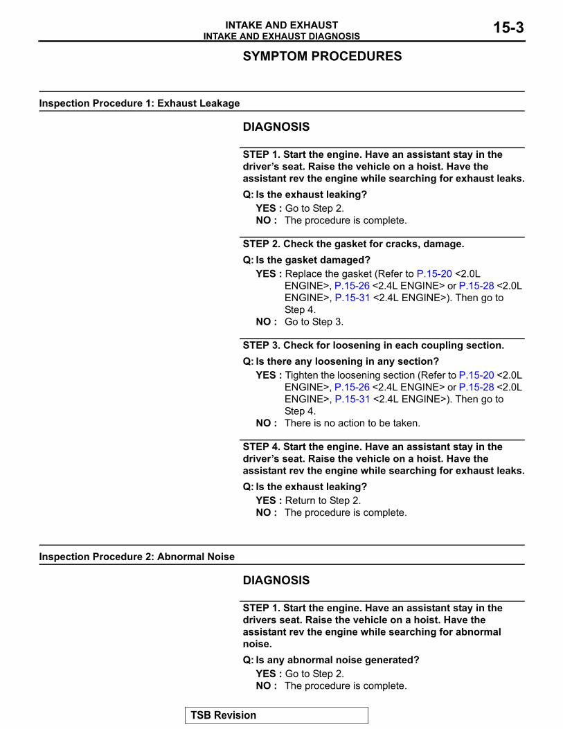
STEP 1. Start the engine. Have an assistant stay in the driver’s seat. Raise the vehicle on a hoist. Have the assistant rev the engine while searching for exhaust leaks.Q: Is the exhaust leaking?
YES : Go to Step 2.NO : The procedure is complete.
STEP 2. Check the gasket for cracks, damage.Q: Is the gasket damaged?
YES : Replace the gasket (Refer to P.15-20 <2.0L ENGINE>, P.15-26 <2.4L ENGINE> or P.15-28 <2.0L ENGINE>, P.15-31 <2.4L ENGINE>). Then go to Step 4.
NO : Go to Step 3.
STEP 3. Check for loosening in each coupling section.Q: Is there any loosening in any section?
YES : Tighten the loosening section (Refer to P.15-20 <2.0L ENGINE>, P.15-26 <2.4L ENGINE> or P.15-28 <2.0L ENGINE>, P.15-31 <2.4L ENGINE>). Then go to Step 4.
NO : There is no action to be taken.
STEP 4. Start the engine. Have an assistant stay in the driver’s seat. Raise the vehicle on a hoist. Have the assistant rev the engine while searching for exhaust leaks.Q: Is the exhaust leaking?
YES : Return to Step 2.NO : The procedure is complete.
Inspection Procedure 2: Abnormal Noise
DIAGNOSIS
STEP 1. Start the engine. Have an assistant stay in the drivers seat. Raise the vehicle on a hoist. Have the assistant rev the engine while searching for abnormal noise.Q: Is any abnormal noise generated?
YES : Go to Step 2.NO : The procedure is complete.
TSB Revision
INTAKE AND EXHAUST DIAGNOSISINTAKE AND EXHAUST15-4
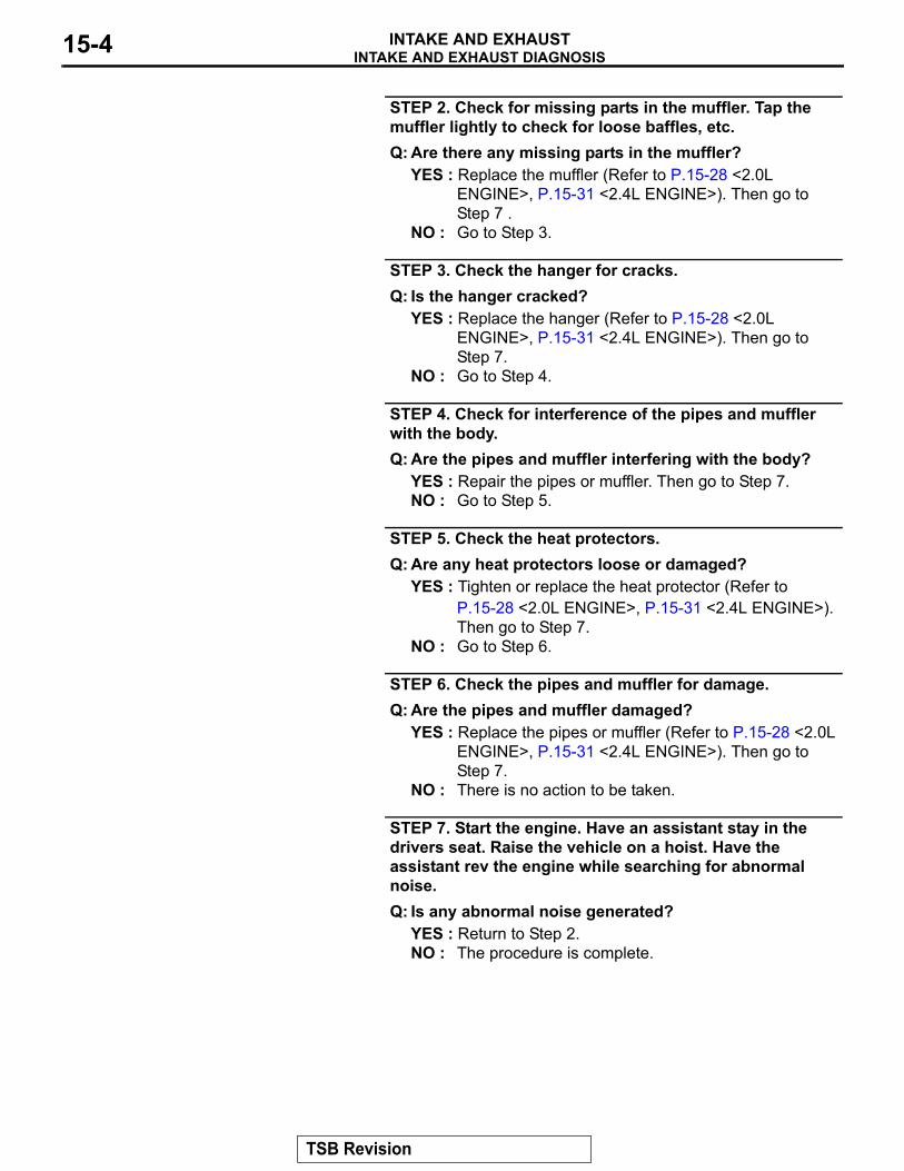
STEP 2. Check for missing parts in the muffler. Tap the muffler lightly to check for loose baffles, etc.Q: Are there any missing parts in the muffler?
YES : Replace the muffler (Refer to P.15-28 <2.0L ENGINE>, P.15-31 <2.4L ENGINE>). Then go to Step 7 .
NO : Go to Step 3.
STEP 3. Check the hanger for cracks.Q: Is the hanger cracked?
YES : Replace the hanger (Refer to P.15-28 <2.0L ENGINE>, P.15-31 <2.4L ENGINE>). Then go to Step 7.
NO : Go to Step 4.
STEP 4. Check for interference of the pipes and muffler with the body.Q: Are the pipes and muffler interfering with the body?
YES : Repair the pipes or muffler. Then go to Step 7.NO : Go to Step 5.
STEP 5. Check the heat protectors.Q: Are any heat protectors loose or damaged?
YES : Tighten or replace the heat protector (Refer to P.15-28 <2.0L ENGINE>, P.15-31 <2.4L ENGINE>). Then go to Step 7.
NO : Go to Step 6.
STEP 6. Check the pipes and muffler for damage.Q: Are the pipes and muffler damaged?
YES : Replace the pipes or muffler (Refer to P.15-28 <2.0L ENGINE>, P.15-31 <2.4L ENGINE>). Then go to Step 7.
NO : There is no action to be taken.
STEP 7. Start the engine. Have an assistant stay in the drivers seat. Raise the vehicle on a hoist. Have the assistant rev the engine while searching for abnormal noise.Q: Is any abnormal noise generated?
YES : Return to Step 2.NO : The procedure is complete.
TSB Revision
SPECIAL TOOLSINTAKE AND EXHAUST 15-5
SPECIAL TOOLSM1151000601381
TROUBLESHOOTINGM1151010200057
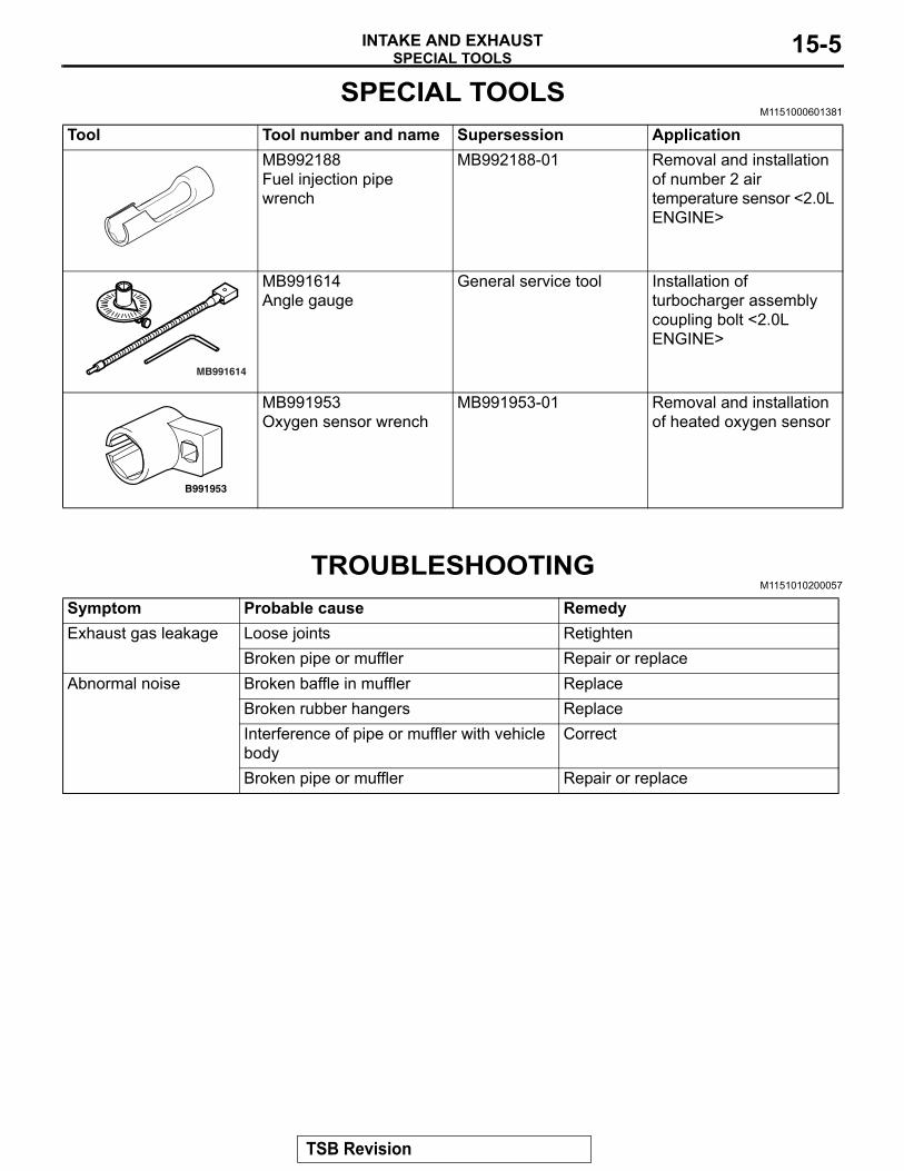
Tool Tool number and name Supersession ApplicationMB992188 Fuel injection pipe wrench
MB992188-01 Removal and installation of number 2 air temperature sensor <2.0L ENGINE>
MB991614Angle gauge
General service tool Installation of turbocharger assembly coupling bolt <2.0L ENGINE>
MB991953 Oxygen sensor wrench
MB991953-01 Removal and installation of heated oxygen sensor
MB991614
B991953
Symptom Probable cause RemedyExhaust gas leakage Loose joints Retighten
Broken pipe or muffler Repair or replaceAbnormal noise Broken baffle in muffler Replace
Broken rubber hangers ReplaceInterference of pipe or muffler with vehicle body
Correct
Broken pipe or muffler Repair or replace
TSB Revision
ON-VEHICLE SERVICE <2.0L ENGINE>INTAKE AND EXHAUST15-6
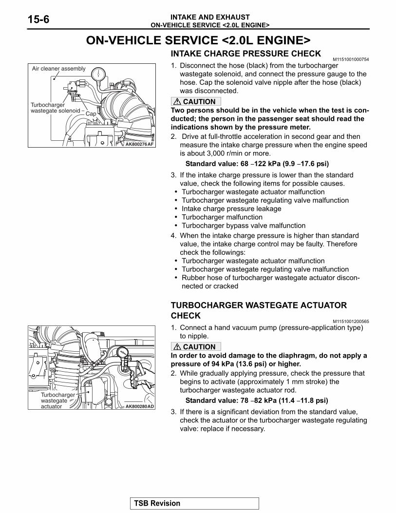
ON-VEHICLE SERVICE <2.0L ENGINE>INTAKE CHARGE PRESSURE CHECK
M11510010007541. Disconnect the hose (black) from the turbocharger
wastegate solenoid, and connect the pressure gauge to the hose. Cap the solenoid valve nipple after the hose (black) was disconnected.CAUTION
Two persons should be in the vehicle when the test is con-ducted; the person in the passenger seat should read the indications shown by the pressure meter.2. Drive at full-throttle acceleration in second gear and then
measure the intake charge pressure when the engine speed is about 3,000 r/min or more.
Standard value: 68 − 122 kPa (9.9 − 17.6 psi)3. If the intake charge pressure is lower than the standard
value, check the following items for possible causes.• Turbocharger wastegate actuator malfunction• Turbocharger wastegate regulating valve malfunction• Intake charge pressure leakage• Turbocharger malfunction• Turbocharger bypass valve malfunction
4. When the intake charge pressure is higher than standard value, the intake charge control may be faulty. Therefore check the followings:
• Turbocharger wastegate actuator malfunction• Turbocharger wastegate regulating valve malfunction• Rubber hose of turbocharger wastegate actuator discon-
nected or cracked
TURBOCHARGER WASTEGATE ACTUATOR CHECK
M11510012005651. Connect a hand vacuum pump (pressure-application type)
to nipple.CAUTION
In order to avoid damage to the diaphragm, do not apply a pressure of 94 kPa (13.6 psi) or higher.2. While gradually applying pressure, check the pressure that
begins to activate (approximately 1 mm stroke) the turbocharger wastegate actuator rod.
Standard value: 78 − 82 kPa (11.4 − 11.8 psi)3. If there is a significant deviation from the standard value,
check the actuator or the turbocharger wastegate regulating valve: replace if necessary.
AK800276AF
Air cleaner assembly
Turbochargerwastegate solenoid Cap
AK800280AD
Turbochargerwastegate actuator
TSB Revision
ON-VEHICLE SERVICE <2.0L ENGINE>INTAKE AND EXHAUST 15-7
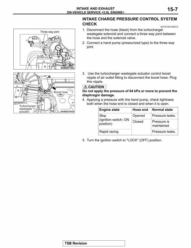
INTAKE CHARGE PRESSURE CONTROL SYSTEM CHECK
M11510011005131. Disconnect the hose (black) from the turbocharger
wastegate solenoid and connect a three way joint between the hose and the solenoid valve.
2. Connect a hand pump (pressurized type) to the three-way joint.
3. Use the turbocharger wastegate actuator control boost nipple of air outlet fitting to disconnect the boost hose. Plug this nipple.CAUTION
Do not apply the pressure of 94 kPa or more to prevent the diaphragm damage.4. Applying a pressure with the hand pump, check tightness
both when the hose end is closed and when it is open.
5. Turn the ignition switch to "LOCK" (OFF) position.
Engine state Hose end Normal stateStop(Ignition switch: ON position)
Opened Pressure leaks.
Closed Pressure is maintained.
Rapid racing Pressure leaks.
AK800277
Three way joint
AD
AK800278AD
Turbochargerwastegate actuator
Boost hose
TSB Revision
ON-VEHICLE SERVICE <2.0L ENGINE>INTAKE AND EXHAUST15-8
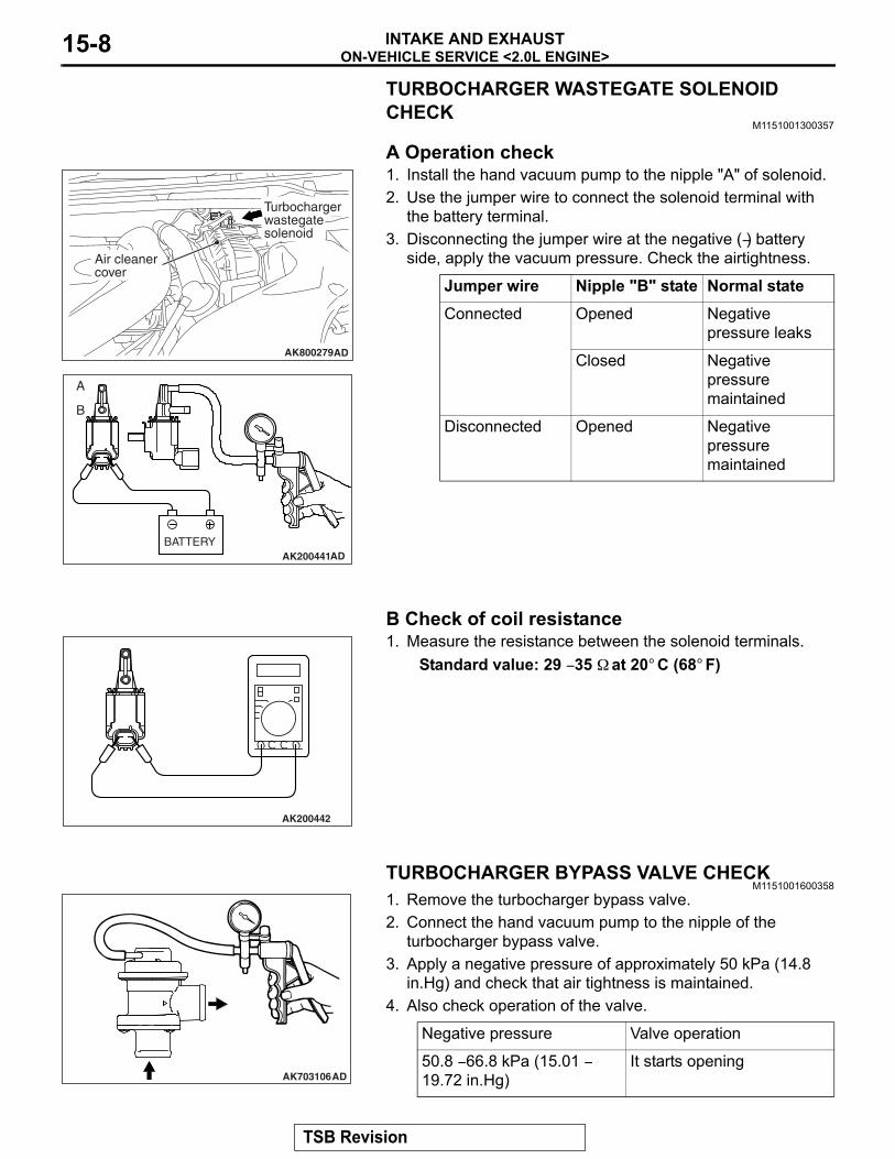
TURBOCHARGER WASTEGATE SOLENOID CHECK
M1151001300357.
A Operation check1. Install the hand vacuum pump to the nipple "A" of solenoid. 2. Use the jumper wire to connect the solenoid terminal with
the battery terminal.3. Disconnecting the jumper wire at the negative (−) battery
side, apply the vacuum pressure. Check the airtightness.
.
B Check of coil resistance1. Measure the resistance between the solenoid terminals.
Standard value: 29 − 35 Ω at 20° C (68° F)
TURBOCHARGER BYPASS VALVE CHECKM1151001600358
1. Remove the turbocharger bypass valve.2. Connect the hand vacuum pump to the nipple of the
turbocharger bypass valve.3. Apply a negative pressure of approximately 50 kPa (14.8
in.Hg) and check that air tightness is maintained.4. Also check operation of the valve.
Jumper wire Nipple "B" state Normal stateConnected Opened Negative
pressure leaks
Closed Negative pressure maintained
Disconnected Opened Negative pressure maintained
AK800279AD
Air cleanercover
Turbochargerwastegatesolenoid
AK200441BATTERY
A
B
AD
AK200442
Negative pressure Valve operation
50.8 − 66.8 kPa (15.01 − 19.72 in.Hg)
It starts openingAK703106AD
TSB Revision
AIR CLEANERINTAKE AND EXHAUST 15-9
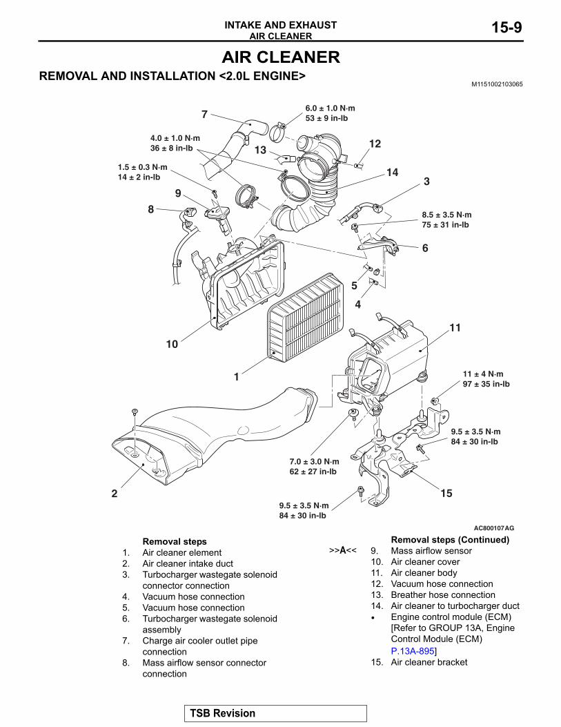
AIR CLEANERREMOVAL AND INSTALLATION <2.0L ENGINE>
M1151002103065
AC800107
2
3
4
6
1
89
7
10
14
1213
11
15
AG
5
8.5 ± 3.5 N·m75 ± 31 in-lb
6.0 ± 1.0 N·m53 ± 9 in-lb
1.5 ± 0.3 N·m14 ± 2 in-lb
7.0 ± 3.0 N·m62 ± 27 in-lb
4.0 ± 1.0 N·m36 ± 8 in-lb
9.5 ± 3.5 N·m84 ± 30 in-lb
9.5 ± 3.5 N·m84 ± 30 in-lb
11 ± 4 N·m97 ± 35 in-lb
Removal steps 1. Air cleaner element2. Air cleaner intake duct3. Turbocharger wastegate solenoid
connector connection4. Vacuum hose connection5. Vacuum hose connection6. Turbocharger wastegate solenoid
assembly7. Charge air cooler outlet pipe
connection8. Mass airflow sensor connector
connection
>>A<< 9. Mass airflow sensor10. Air cleaner cover11. Air cleaner body12. Vacuum hose connection13. Breather hose connection14. Air cleaner to turbocharger duct• Engine control module (ECM)
[Refer to GROUP 13A, Engine Control Module (ECM) P.13A-895]
15. Air cleaner bracket
Removal steps (Continued)
TSB Revision
AIR CLEANERINTAKE AND EXHAUST15-10
INSTALLATION SERVICE POINT.
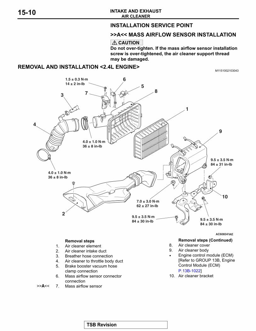
>>A<< MASS AIRFLOW SENSOR INSTALLATIONCAUTION
Do not over-tighten. If the mass airflow sensor installation screw is over-tightened, the air cleaner support thread may be damaged.
REMOVAL AND INSTALLATION <2.4L ENGINE>M1151002103043
AC608341
1
2
3
4
56
7 8
9
10
4.0 ± 1.0 N·m36 ± 8 in-lb
4.0 ± 1.0 N·m36 ± 8 in-lb
1.5 ± 0.3 N·m14 ± 2 in-lb
7.0 ± 3.0 N·m62 ± 27 in-lb
9.5 ± 3.5 N·m84 ± 30 in-lb 9.5 ± 3.5 N·m
84 ± 30 in-lb
9.5 ± 3.5 N·m84 ± 31 in-lb
AE
Removal steps 1. Air cleaner element2. Air cleaner intake duct3. Breather hose connection4. Air cleaner to throttle body duct5. Brake booster vacuum hose
clamp connection6. Mass airflow sensor connector
connection>>A<< 7. Mass airflow sensor
8. Air cleaner cover9. Air cleaner body• Engine control module (ECM)
[Refer to GROUP 13B, Engine Control Module (ECM) P.13B-1022]
10. Air cleaner bracket
Removal steps (Continued)
TSB Revision
CHARGE AIR COOLER <2.0L ENGINE>INTAKE AND EXHAUST 15-11
INSTALLATION SERVICE POINT.
>>A<< MASS AIRFLOW SENSOR INSTALLATIONCAUTION
Do not over-tighten. If the mass airflow sensor mounting screw is over-tightened, the air cleaner support thread can be damaged.
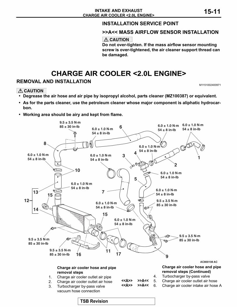
CHARGE AIR COOLER <2.0L ENGINE>REMOVAL AND INSTALLATION
M1151002400971
CAUTION• Degrease the air hose and air pipe by isopropyl alcohol, parts cleaner (MZ100387) or equivalent.• As for the parts cleaner, use the petroleum cleaner whose major component is aliphatic hydrocar-
bon.• Working area should be airy and kept from flame.
AC800108
1
2
3 4
5
7
9
15
17
14
15
6
8
13
AC
16
12
11
10
6.0 ± 1.0 N·m54 ± 8 in-lb
6.0 ± 1.0 N·m54 ± 8 in-lb 6.0 ± 1.0 N·m
54 ± 8 in-lb
6.0 ± 1.0 N·m54 ± 8 in-lb
6.0 ± 1.0 N·m54 ± 8 in-lb
6.0 ± 1.0 N·m54 ± 8 in-lb
6.0 ± 1.0 N·m54 ± 8 in-lb
6.0 ± 1.0 N·m54 ± 8 in-lb
6.0 ± 1.0 N·m54 ± 8 in-lb
6.0 ± 1.0 N·m54 ± 8 in-lb
6.0 ± 1.0 N·m54 ± 8 in-lb
9.5 ± 3.5 N·m85 ± 30 in-lb
9.5 ± 3.5 N·m85 ± 30 in-lb
9.5 ± 3.5 N·m85 ± 30 in-lb
9.5 ± 3.5 N·m85 ± 30 in-lb
9.5 ± 3.5 N·m85 ± 30 in-lb
Charge air cooler hose and pipe removal steps
1. Charge air cooler outlet air pipe2. Charge air cooler outlet air hose3. Turbocharger by-pass valve
vacuum hose connection
4. Turbocharger by-pass valve<<A>> >>A<< 5. Charge air cooler outlet air hose<<A>> >>A<< 6. Charge air cooler intake air hose A
Charge air cooler hose and pipe removal steps (Continued)
TSB Revision
CHARGE AIR COOLER <2.0L ENGINE>INTAKE AND EXHAUST15-12
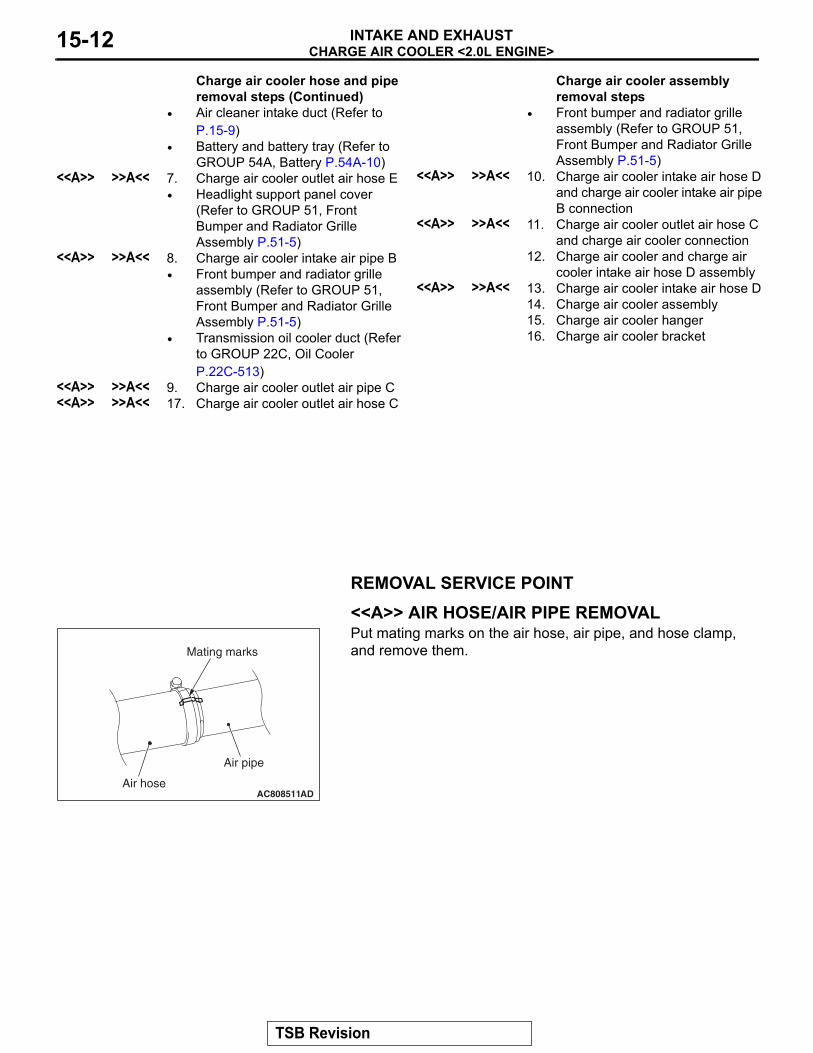
REMOVAL SERVICE POINT.
<<A>> AIR HOSE/AIR PIPE REMOVALPut mating marks on the air hose, air pipe, and hose clamp, and remove them.
• Air cleaner intake duct (Refer to P.15-9)
• Battery and battery tray (Refer to GROUP 54A, Battery P.54A-10)
<<A>> >>A<< 7. Charge air cooler outlet air hose E• Headlight support panel cover
(Refer to GROUP 51, Front Bumper and Radiator Grille Assembly P.51-5)
<<A>> >>A<< 8. Charge air cooler intake air pipe B• Front bumper and radiator grille
assembly (Refer to GROUP 51, Front Bumper and Radiator Grille Assembly P.51-5)
• Transmission oil cooler duct (Refer to GROUP 22C, Oil Cooler P.22C-513)
<<A>> >>A<< 9. Charge air cooler outlet air pipe C<<A>> >>A<< 17. Charge air cooler outlet air hose C
Charge air cooler hose and pipe removal steps (Continued)
Charge air cooler assembly removal steps
• Front bumper and radiator grille assembly (Refer to GROUP 51, Front Bumper and Radiator Grille Assembly P.51-5)
<<A>> >>A<< 10. Charge air cooler intake air hose D and charge air cooler intake air pipe B connection
<<A>> >>A<< 11. Charge air cooler outlet air hose C and charge air cooler connection
12. Charge air cooler and charge air cooler intake air hose D assembly
<<A>> >>A<< 13. Charge air cooler intake air hose D14. Charge air cooler assembly15. Charge air cooler hanger16. Charge air cooler bracket
AC808511
Air pipe
AD
Mating marks
Air hose
TSB Revision
CHARGE AIR COOLER <2.0L ENGINE>INTAKE AND EXHAUST 15-13
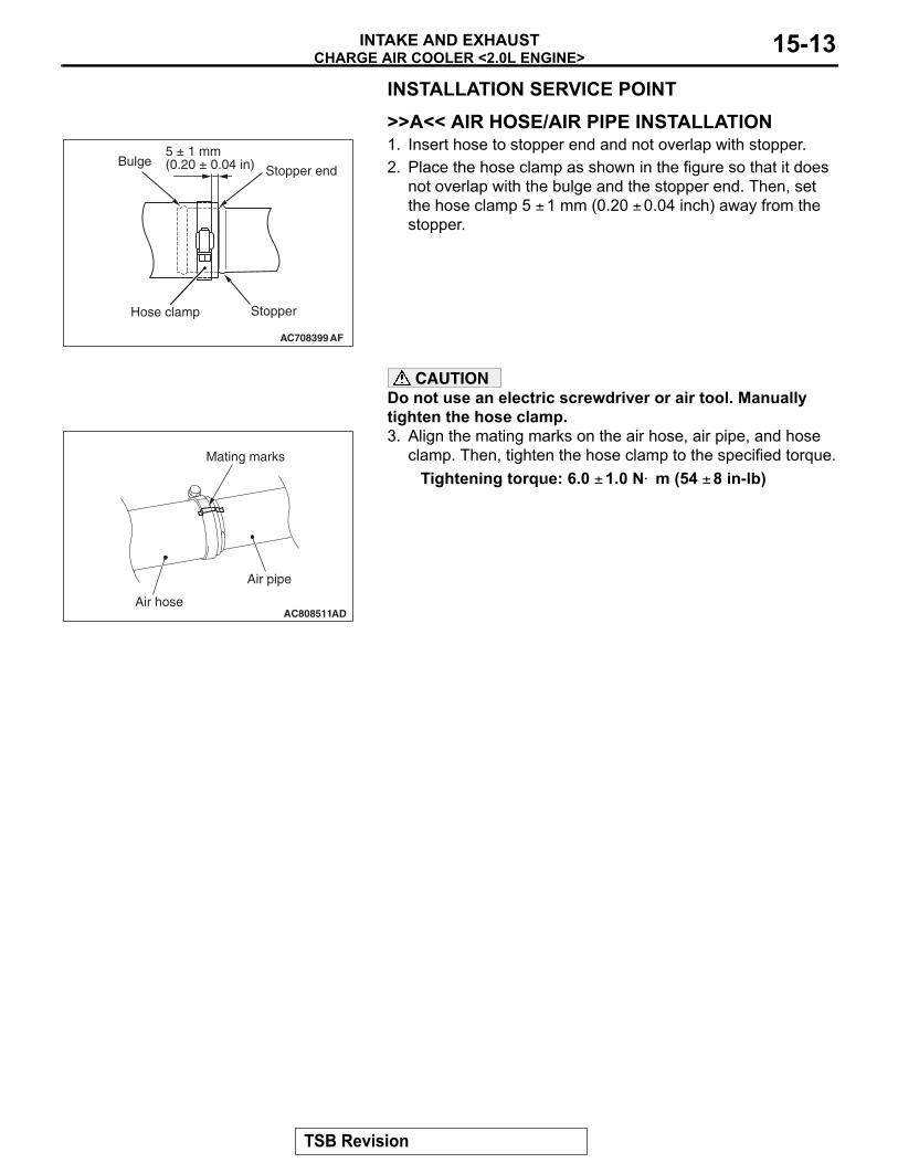
INSTALLATION SERVICE POINT.
>>A<< AIR HOSE/AIR PIPE INSTALLATION1. Insert hose to stopper end and not overlap with stopper.2. Place the hose clamp as shown in the figure so that it does
not overlap with the bulge and the stopper end. Then, set the hose clamp 5 ± 1 mm (0.20 ± 0.04 inch) away from the stopper.
CAUTIONDo not use an electric screwdriver or air tool. Manually tighten the hose clamp.3. Align the mating marks on the air hose, air pipe, and hose
clamp. Then, tighten the hose clamp to the specified torque.Tightening torque: 6.0 ± 1.0 N⋅ m (54 ± 8 in-lb)
AC708399
Stopper end
AF
Stopper
Bulge
Hose clamp
5 ± 1 mm(0.20 ± 0.04 in)
AC808511
Air pipe
AD
Mating marks
Air hose
TSB Revision
INTAKE MANIFOLDINTAKE AND EXHAUST15-14
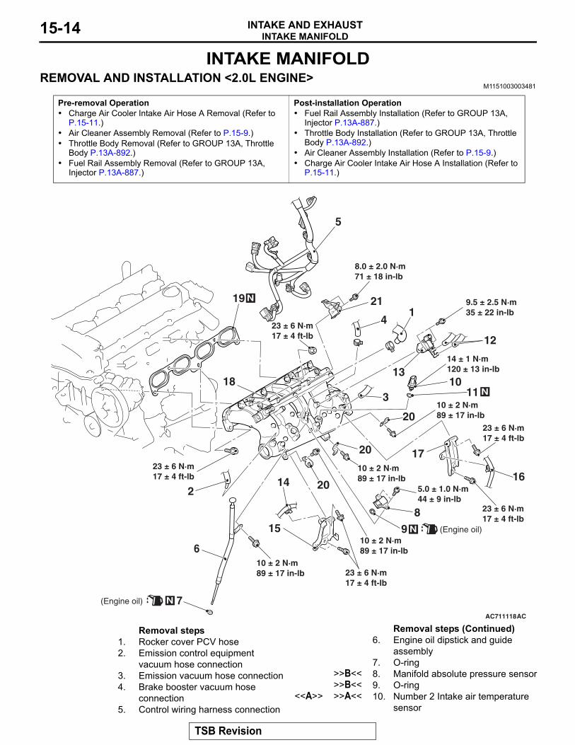
INTAKE MANIFOLDREMOVAL AND INSTALLATION <2.0L ENGINE>
M1151003003481
Pre-removal Operation• Charge Air Cooler Intake Air Hose A Removal (Refer to
P.15-11.)• Air Cleaner Assembly Removal (Refer to P.15-9.)• Throttle Body Removal (Refer to GROUP 13A, Throttle
Body P.13A-892.)• Fuel Rail Assembly Removal (Refer to GROUP 13A,
Injector P.13A-887.)
Post-installation Operation• Fuel Rail Assembly Installation (Refer to GROUP 13A,
Injector P.13A-887.)• Throttle Body Installation (Refer to GROUP 13A, Throttle
Body P.13A-892.)• Air Cleaner Assembly Installation (Refer to P.15-9.)• Charge Air Cooler Intake Air Hose A Installation (Refer to
P.15-11.)
AC711118
5
3
2
6
18
15
119 N
10
17
20
8
13
12
N9 (Engine oil)
21
20
AC
20
23 ± 6 N·m17 ± 4 ft-lb
10 ± 2 N·m89 ± 17 in-lb
23 ± 6 N·m17 ± 4 ft-lb
23 ± 6 N·m17 ± 4 ft-lb
23 ± 6 N·m17 ± 4 ft-lb
8.0 ± 2.0 N·m71 ± 18 in-lb
9.5 ± 2.5 N·m35 ± 22 in-lb
5.0 ± 1.0 N·m44 ± 9 in-lb
10 ± 2 N·m89 ± 17 in-lb
10 ± 2 N·m89 ± 17 in-lb
14 ± 1 N·m120 ± 13 in-lb
10 ± 2 N·m89 ± 17 in-lb
7
14
23 ± 6 N·m17 ± 4 ft-lb
16
N
11 N
(Engine oil)
4
Removal steps 1. Rocker cover PCV hose2. Emission control equipment
vacuum hose connection3. Emission vacuum hose connection4. Brake booster vacuum hose
connection5. Control wiring harness connection
6. Engine oil dipstick and guide assembly
7. O-ring>>B<< 8. Manifold absolute pressure sensor>>B<< 9. O-ring
<<A>> >>A<< 10. Number 2 Intake air temperature sensor
Removal steps (Continued)
TSB Revision
INTAKE MANIFOLDINTAKE AND EXHAUST 15-15
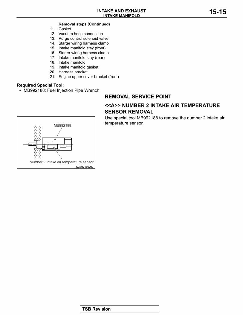
Required Special Tool:• MB992188: Fuel Injection Pipe Wrench
REMOVAL SERVICE POINT.
<<A>> NUMBER 2 INTAKE AIR TEMPERATURE SENSOR REMOVALUse special tool MB992188 to remove the number 2 intake air temperature sensor.
11. Gasket12. Vacuum hose connection13. Purge control solenoid valve14. Starter wiring harness clamp15. Intake manifold stay (front)16. Starter wiring harness clamp17. Intake manifold stay (rear)18. Intake manifold19. Intake manifold gasket20. Harness bracket21. Engine upper cover bracket (front)
Removal steps (Continued)
AC707100
MB992188
AD
Number 2 Intake air temperature sensor
TSB Revision
INTAKE MANIFOLDINTAKE AND EXHAUST15-16
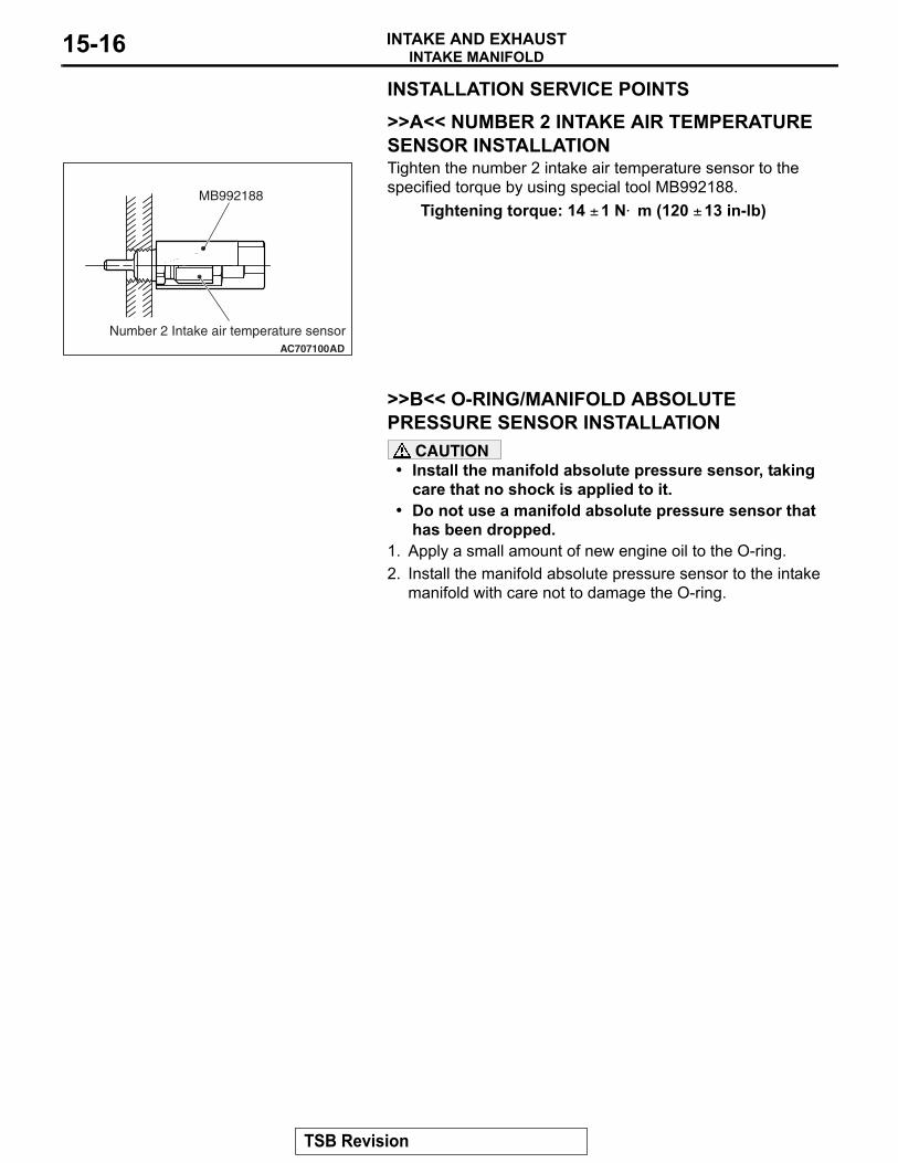
INSTALLATION SERVICE POINTS.
>>A<< NUMBER 2 INTAKE AIR TEMPERATURE SENSOR INSTALLATIONTighten the number 2 intake air temperature sensor to the specified torque by using special tool MB992188.
Tightening torque: 14 ± 1 N⋅ m (120 ± 13 in-lb)
.
>>B<< O-RING/MANIFOLD ABSOLUTE PRESSURE SENSOR INSTALLATION
CAUTION• Install the manifold absolute pressure sensor, taking
care that no shock is applied to it.• Do not use a manifold absolute pressure sensor that
has been dropped.1. Apply a small amount of new engine oil to the O-ring.2. Install the manifold absolute pressure sensor to the intake
manifold with care not to damage the O-ring.
AC707100
MB992188
AD
Number 2 Intake air temperature sensor
TSB Revision
INTAKE MANIFOLDINTAKE AND EXHAUST 15-17
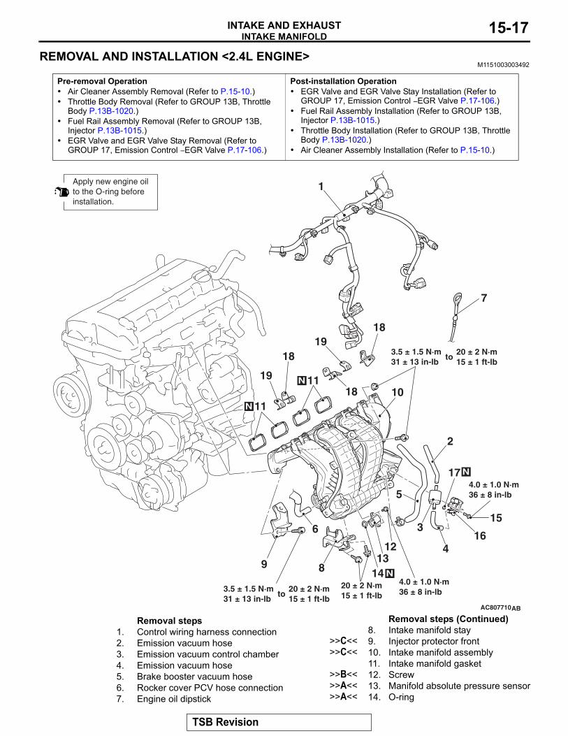
REMOVAL AND INSTALLATION <2.4L ENGINE>M1151003003492
Pre-removal Operation• Air Cleaner Assembly Removal (Refer to P.15-10.)• Throttle Body Removal (Refer to GROUP 13B, Throttle
Body P.13B-1020.)• Fuel Rail Assembly Removal (Refer to GROUP 13B,
Injector P.13B-1015.)• EGR Valve and EGR Valve Stay Removal (Refer to
GROUP 17, Emission Control − EGR Valve P.17-106.)
Post-installation Operation• EGR Valve and EGR Valve Stay Installation (Refer to
GROUP 17, Emission Control − EGR Valve P.17-106.)• Fuel Rail Assembly Installation (Refer to GROUP 13B,
Injector P.13B-1015.) • Throttle Body Installation (Refer to GROUP 13B, Throttle
Body P.13B-1020.)• Air Cleaner Assembly Installation (Refer to P.15-10.)
AC807710AB
1
3
5
6
9
10
12
8
7
20 ± 2 N·m15 ± 1 ft-lb
N 11
11N
13
15
16
18
18
1918
19
3.5 ± 1.5 N·m31 ± 13 in-lb
N14
N17
2
4
to20 ± 2 N·m15 ± 1 ft-lb
3.5 ± 1.5 N·m31 ± 13 in-lb
to20 ± 2 N·m15 ± 1 ft-lb
4.0 ± 1.0 N·m36 ± 8 in-lb
4.0 ± 1.0 N·m36 ± 8 in-lb
Apply new engine oil to the O-ring beforeinstallation.
Removal steps 1. Control wiring harness connection2. Emission vacuum hose3. Emission vacuum control chamber4. Emission vacuum hose5. Brake booster vacuum hose6. Rocker cover PCV hose connection7. Engine oil dipstick
8. Intake manifold stay>>C<< 9. Injector protector front>>C<< 10. Intake manifold assembly
11. Intake manifold gasket>>B<< 12. Screw>>A<< 13. Manifold absolute pressure sensor>>A<< 14. O-ring
Removal steps (Continued)
TSB Revision
INTAKE MANIFOLDINTAKE AND EXHAUST15-18
INSTALLATION SERVICE POINTS.
>>A<< O-RING/PURGE CONTROL SOLENOID VALVE/O-RING/MANIFOLD ABSOLUTE PRES-SURE SENSOR INSTALLATION
CAUTION• When applying the engine oil, make sure not to allow
the engine oil to enter the intake manifold inside.• Install the manifold absolute pressure sensor, taking
care that no shock is applied to it.• Do not use a manifold absolute pressure sensor that
has been dropped.1. Apply a small amount of new engine oil to the O-ring.2. While turning the purge control solenoid valve or manifold
absolute pressure sensor to right and left, install the O-ring to the purge control solenoid valve or manifold absolute pressure sensor with care to avoid damage to the O-ring.
3. Turning the purge control solenoid valve or manifold absolute pressure sensor to right and left, install it to the intake manifold with care not to damage the O-ring. After the installation, check for its smooth rotation.
.
>>B<< SCREW INSTALLATIONCAUTION
Do not over-tighten. As the self-forming-type screw is used, the excessive torque can damage the intake mani-fold threads..
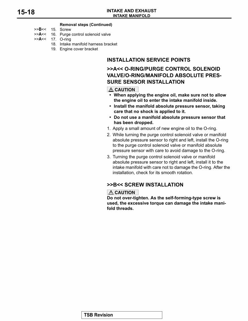
>>B<< 15. Screw>>A<< 16. Purge control solenoid valve>>A<< 17. O-ring
18. Intake manifold harness bracket19. Engine cover bracket
Removal steps (Continued)
TSB Revision
INTAKE MANIFOLDINTAKE AND EXHAUST 15-19
>>C<< INTAKE MANIFOLD ASSEMBLY/INJECTOR PROTECTOR FRONT INSTALLATIONInstall the intake manifold assembly and the injector protector front, and tighten mounting bolts and nuts temporarily.NOTE: The tightening of the fuel rail assembly, the intake man-ifold assembly and the injector protector front has the specified order. Temporarily tighten the intake manifold assembly and injector protector front mounting bolts and nuts (Refer to GROUP 13B, Injector P.13B-1015.)
INSPECTIONM1151003101341
.
INTAKE MANIFOLD CHECK1. Check the intake manifold for damage and cracks, and
replace it if necessary.2. Check the vacuum outlet port for clogging, and clean it if
necessary.
TSB Revision
EXHAUST MANIFOLD AND TURBOCHARGER <2.0L ENGINE>INTAKE AND EXHAUST15-20
EXHAUST MANIFOLD AND TURBOCHARGER <2.0L ENGINE>
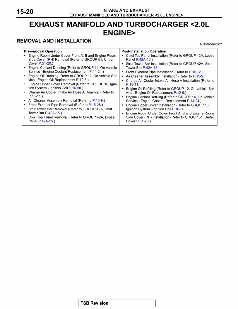
REMOVAL AND INSTALLATIONM1151008900907
Pre-removal Operation• Engine Room Under Cover Front A, B and Engine Room
Side Cover (RH) Removal (Refer to GROUP 51, Under Cover P.51-20.)
• Engine Coolant Draining (Refer to GROUP 14, On-vehicle Service − Engine Coolant Replacement P.14-24.)
• Engine Oil Draining (Refer to GROUP 12, On-vehicle Ser-vice − Engine Oil Replacement P.12-5.)
• Engine Upper Cover Removal (Refer to GROUP 16, Igni-tion System − Ignition Coil P.16-50.)
• Charge Air Cooler Intake Air Hose A Removal (Refer to P.15-11.)
• Air Cleaner Assembly Removal (Refer to P.15-9.)• Front Exhaust Pipe Removal (Refer to P.15-28.)• Strut Tower Bar Removal (Refer to GROUP 42A, Strut
Tower Bar P.42A-15.)• Cowl Top Panel Removal (Refer to GROUP 42A, Loose
Panel P.42A-15.)
Post-installation Operation• Cowl Top Panel Installation (Refer to GROUP 42A, Loose
Panel P.42A-15.)• Strut Tower Bar Installation (Refer to GROUP 42A, Strut
Tower Bar P.42A-15.)• Front Exhaust Pipe Installation (Refer to P.15-28.)• Air Cleaner Assembly Installation (Refer to P.15-9.)• Charge Air Cooler Intake Air Hose A Installation (Refer to
P.15-11.)• Engine Oil Refilling (Refer to GROUP 12, On-vehicle Ser-
vice − Engine Oil Replacement P.12-5.)• Engine Coolant Refilling (Refer to GROUP 14, On-vehicle
Service − Engine Coolant Replacement P.14-24.)• Engine Upper Cover Installation (Refer to GROUP 16,
Ignition System − Ignition Coil P.16-50.)• Engine Room Under Cover Front A, B and Engine Room
Side Cover (RH) Installation (Refer to GROUP 51, Under Cover P.51-20.)
TSB Revision
EXHAUST MANIFOLD AND TURBOCHARGER <2.0L ENGINE>INTAKE AND EXHAUST 15-21
AC800109AC
271N
12
3
4
5N
6
8
9
10 N16
11 13
12
14
15
1718N
19
20
21N
22
24 N (Engine oil)
25 25
2628
30
31
N
29
7
23N
7.0 ± 3.0 N·m62 ± 26 in-lb
10 ± 2 N·m89 ± 17 in-lb
10 ± 2 N·m89 ± 17 in-lb
10 ± 2 N·m89 ± 17 in-lb
25 ± 4 N·m19 ± 2 ft-lb
9.5 ± 1.5 N·m85 ± 13 in-lb
28 ± 5 N·m21 ± 3 ft-lb
10 ± 2 N·m89 ± 17 in-lb
8.5 ± 1.5 N·m76 ± 13 in-lb
5.0 ± 2.0 N·m45 ± 17 in-lb
5.0 ± 2.0 N·m45 ± 17 in-lb
25 ± 4 N·m19 ± 3 ft-lb
25 ± 4 N·m19 ± 2 ft-lb
64 ± 5 N·m48 ± 3 ft-lb
64 ± 5 N·m48 ± 3 ft-lb
51 ± 7 N·m38 ± 5 ft-lb
64 ± 5 N·m48 ± 3 ft-lb
9.5 ± 2.5 N·m85 ± 22 in-lb
17 ± 2 N·m13 ± 1 ft-lb
9.0 ± 1.0 N·m80 ± 8 in-lb
9.0 ± 1.0 N·m80 ± 8 in-lb
29 ± 2 N·m22 ± 1 ft-lb
to +65˚ ± 5˚
49 ± 5 N·m37 ± 3 ft-lb
51 ± 7 N·m38 ± 5 ft-lb25 ± 4 N·m
19 ± 2 ft-lb
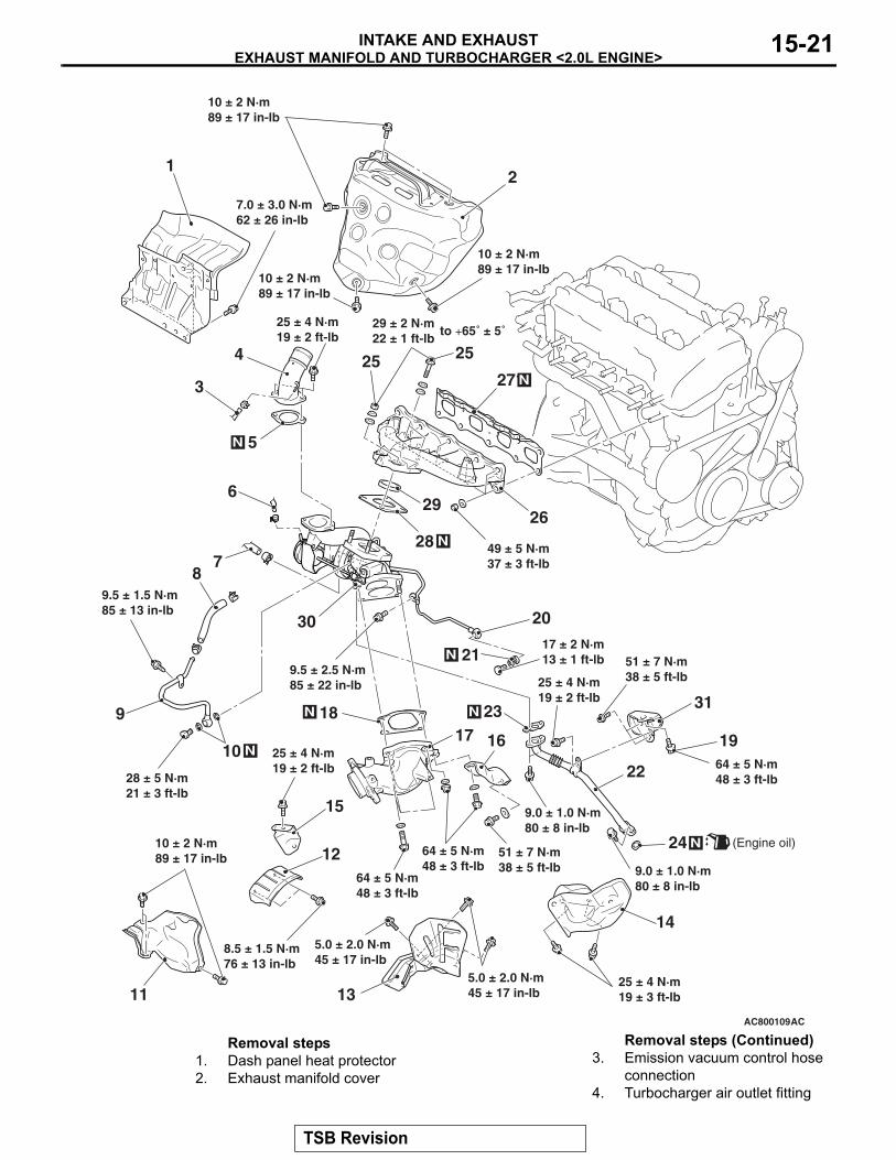
Removal steps 1. Dash panel heat protector2. Exhaust manifold cover
3. Emission vacuum control hose connection
4. Turbocharger air outlet fitting
Removal steps (Continued)
TSB Revision
EXHAUST MANIFOLD AND TURBOCHARGER <2.0L ENGINE>INTAKE AND EXHAUST15-22
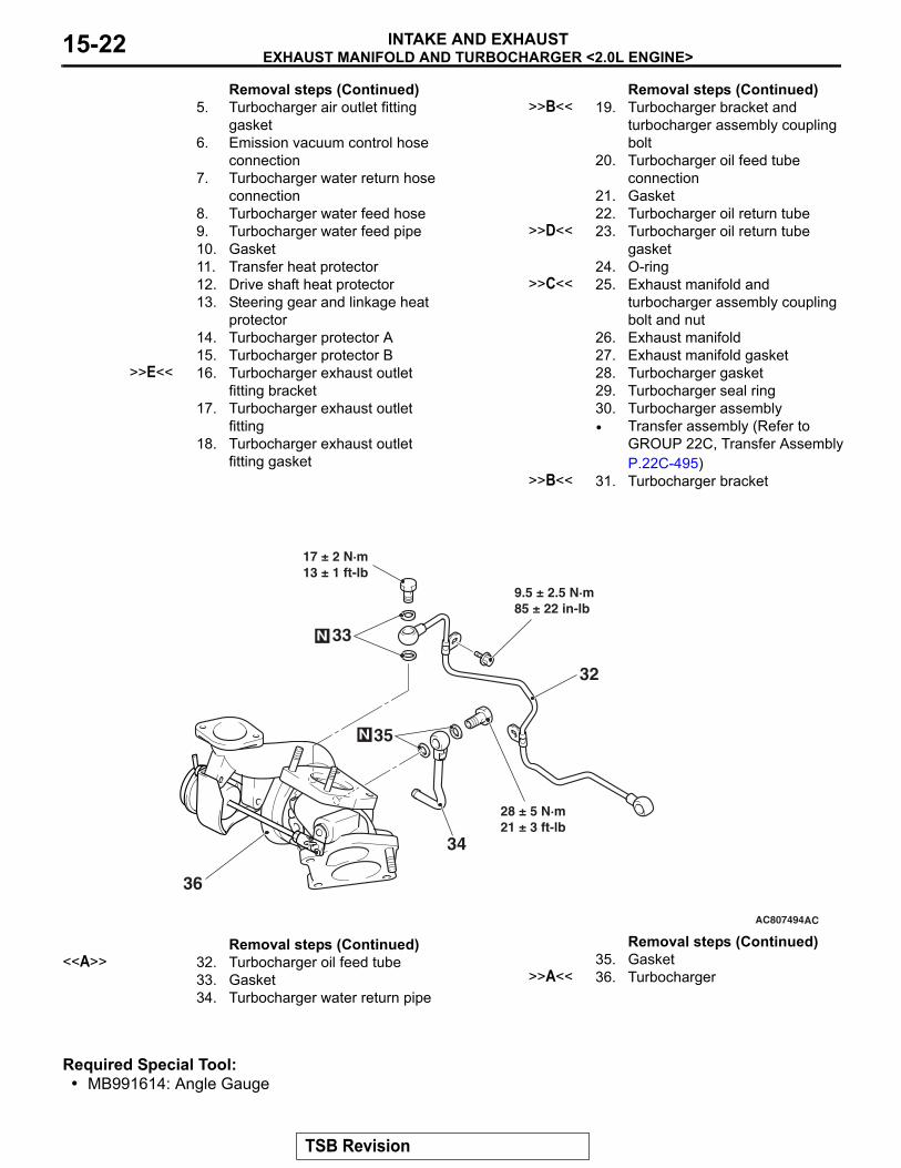
Required Special Tool:• MB991614: Angle Gauge
5. Turbocharger air outlet fitting gasket
6. Emission vacuum control hose connection
7. Turbocharger water return hose connection
8. Turbocharger water feed hose9. Turbocharger water feed pipe10. Gasket11. Transfer heat protector12. Drive shaft heat protector13. Steering gear and linkage heat
protector14. Turbocharger protector A15. Turbocharger protector B
>>E<< 16. Turbocharger exhaust outlet fitting bracket
17. Turbocharger exhaust outlet fitting
18. Turbocharger exhaust outlet fitting gasket
Removal steps (Continued)>>B<< 19. Turbocharger bracket and
turbocharger assembly coupling bolt
20. Turbocharger oil feed tube connection
21. Gasket22. Turbocharger oil return tube
>>D<< 23. Turbocharger oil return tube gasket
24. O-ring>>C<< 25. Exhaust manifold and
turbocharger assembly coupling bolt and nut
26. Exhaust manifold27. Exhaust manifold gasket28. Turbocharger gasket29. Turbocharger seal ring30. Turbocharger assembly• Transfer assembly (Refer to
GROUP 22C, Transfer Assembly P.22C-495)
>>B<< 31. Turbocharger bracket
Removal steps (Continued)
AC807494
32
33
34
35
36
N
N
AC
17 ± 2 N·m13 ± 1 ft-lb
9.5 ± 2.5 N·m85 ± 22 in-lb
28 ± 5 N·m21 ± 3 ft-lb
Removal steps (Continued) <<A>> 32. Turbocharger oil feed tube
33. Gasket34. Turbocharger water return pipe
35. Gasket>>A<< 36. Turbocharger
Removal steps (Continued)
TSB Revision
EXHAUST MANIFOLD AND TURBOCHARGER <2.0L ENGINE>INTAKE AND EXHAUST 15-23
REMOVAL SERVICE POINT.
<<A>> TURBOCHARGER OIL FEED TUBE REMOVAL
CAUTIONTake care not to allow foreign objects to get into the oil passage hole of the turbocharger assembly after the turbo-charger oil feed tube is removed.
INSTALLATION SERVICE POINTS.
>>A<< TURBOCHARGER INSTALLATION1. Clean the fitting between turbocharger oil tube and
turbocharger water pipe, the inside of eye bolts, the inside of tube and the inside of pipe for clogs.CAUTION
Take care not to allow foreign objects to get into the turbo-charger.2. Clean or use compressed air to remove any carbon particles
stuck to the oil passage of the turbocharger.3. Refill new engine oil at the turbocharger oil feed tube fitting
hole of the turbocharger..
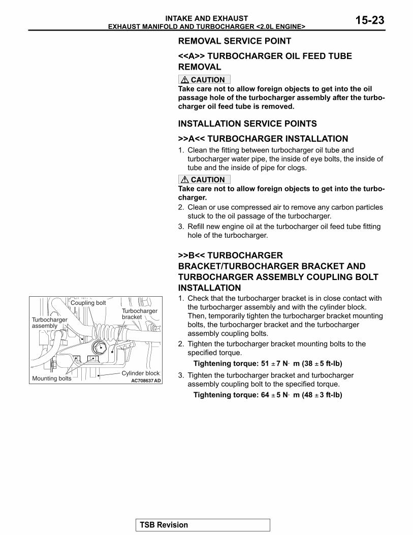
>>B<< TURBOCHARGER BRACKET/TURBOCHARGER BRACKET AND TURBOCHARGER ASSEMBLY COUPLING BOLT INSTALLATION1. Check that the turbocharger bracket is in close contact with
the turbocharger assembly and with the cylinder block. Then, temporarily tighten the turbocharger bracket mounting bolts, the turbocharger bracket and the turbocharger assembly coupling bolts.
2. Tighten the turbocharger bracket mounting bolts to the specified torque.
Tightening torque: 51 ± 7 N⋅ m (38 ± 5 ft-lb)3. Tighten the turbocharger bracket and turbocharger
assembly coupling bolt to the specified torque.Tightening torque: 64 ± 5 N⋅ m (48 ± 3 ft-lb)
.
AC708637AD
Cylinder blockMounting bolts
Turbochargerassembly
Turbochargerbracket
Coupling bolt
TSB Revision
EXHAUST MANIFOLD AND TURBOCHARGER <2.0L ENGINE>INTAKE AND EXHAUST15-24
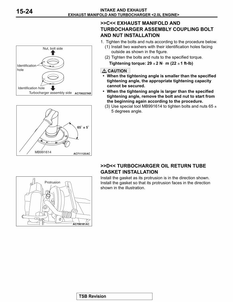
>>C<< EXHAUST MANIFOLD AND TURBOCHARGER ASSEMBLY COUPLING BOLT AND NUT INSTALLATION1. Tighten the bolts and nuts according to the procedure below.
(1) Install two washers with their identification holes facing outside as shown in the figure.
(2) Tighten the bolts and nuts to the specified torque.Tightening torque: 29 ± 2 N⋅ m (22 ± 1 ft-lb)
CAUTION• When the tightening angle is smaller than the specified
tightening angle, the appropriate tightening capacity cannot be secured.
• When the tightening angle is larger than the specified tightening angle, remove the bolt and nut to start from the beginning again according to the procedure.
(3) Use special tool MB991614 to tighten bolts and nuts 65 ± 5 degrees angle.
.
>>D<< TURBOCHARGER OIL RETURN TUBE GASKET INSTALLATIONInstall the gasket as its protrusion is in the direction shown. Install the gasket so that its protrusion faces in the direction shown in the illustration.
.
AC706227
Identificationhole
AB
Identification holeTurbocharger assembly side
Nut, bolt side
AC711125
65˚ ± 5˚
ACMB991614
AC706181AC
Protrusion
TSB Revision
EXHAUST MANIFOLD AND TURBOCHARGER <2.0L ENGINE>INTAKE AND EXHAUST 15-25
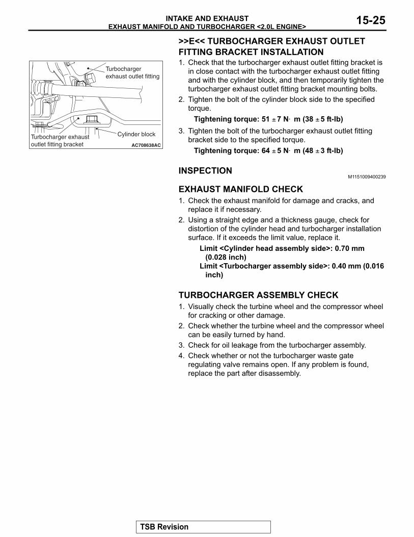
>>E<< TURBOCHARGER EXHAUST OUTLET FITTING BRACKET INSTALLATION1. Check that the turbocharger exhaust outlet fitting bracket is
in close contact with the turbocharger exhaust outlet fitting and with the cylinder block, and then temporarily tighten the turbocharger exhaust outlet fitting bracket mounting bolts.
2. Tighten the bolt of the cylinder block side to the specified torque.
Tightening torque: 51 ± 7 N⋅ m (38 ± 5 ft-lb)3. Tighten the bolt of the turbocharger exhaust outlet fitting
bracket side to the specified torque.Tightening torque: 64 ± 5 N⋅ m (48 ± 3 ft-lb)
INSPECTIONM1151009400239
.
EXHAUST MANIFOLD CHECK1. Check the exhaust manifold for damage and cracks, and
replace it if necessary.2. Using a straight edge and a thickness gauge, check for
distortion of the cylinder head and turbocharger installation surface. If it exceeds the limit value, replace it.
Limit <Cylinder head assembly side>: 0.70 mm (0.028 inch)
Limit <Turbocharger assembly side>: 0.40 mm (0.016 inch)
.
TURBOCHARGER ASSEMBLY CHECK1. Visually check the turbine wheel and the compressor wheel
for cracking or other damage.2. Check whether the turbine wheel and the compressor wheel
can be easily turned by hand.3. Check for oil leakage from the turbocharger assembly.4. Check whether or not the turbocharger waste gate
regulating valve remains open. If any problem is found, replace the part after disassembly.
AC708638AC
Cylinder blockTurbocharger exhaust outlet fitting bracket
Turbocharger exhaust outlet fitting
TSB Revision
EXHAUST MANIFOLD <2.4L ENGINE>INTAKE AND EXHAUST15-26
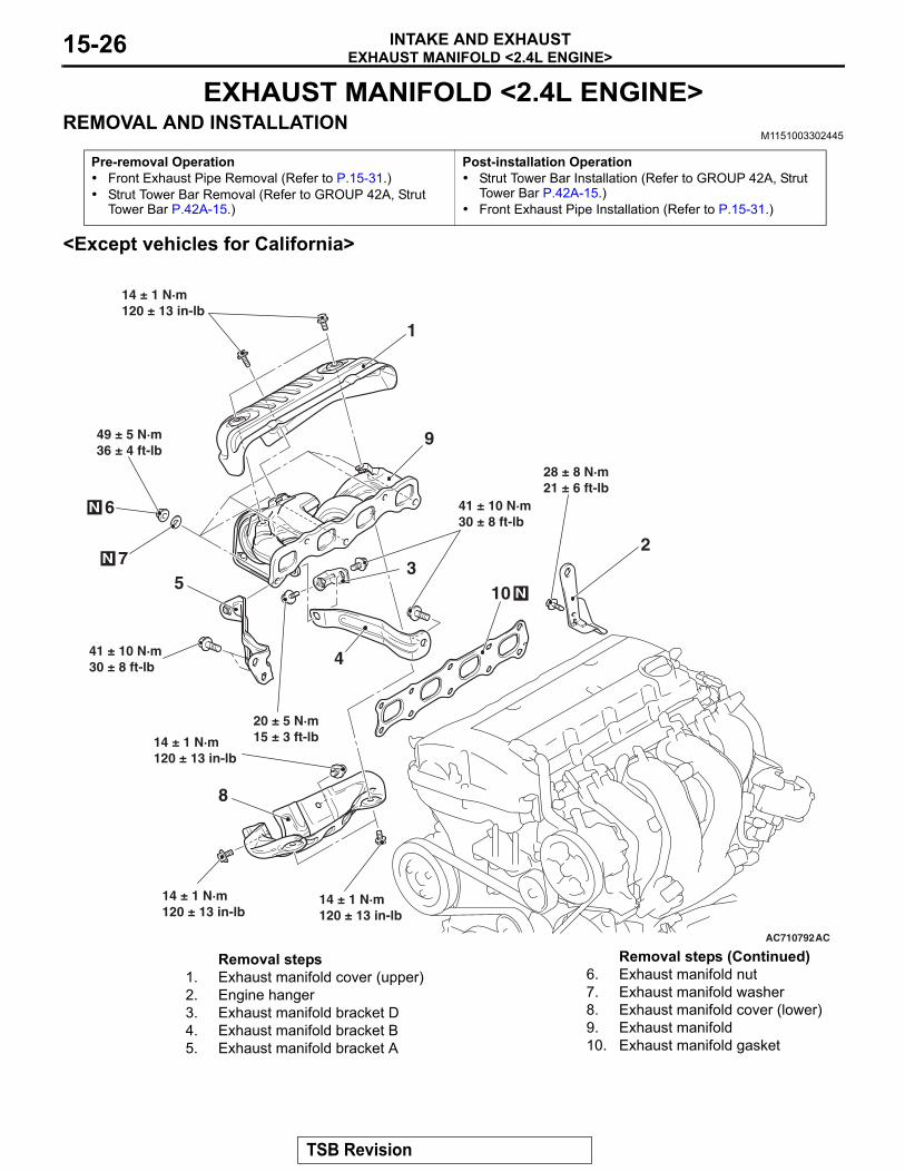
EXHAUST MANIFOLD <2.4L ENGINE>REMOVAL AND INSTALLATION
M1151003302445
<Except vehicles for California>
Pre-removal Operation• Front Exhaust Pipe Removal (Refer to P.15-31.)• Strut Tower Bar Removal (Refer to GROUP 42A, Strut
Tower Bar P.42A-15.)
Post-installation Operation• Strut Tower Bar Installation (Refer to GROUP 42A, Strut
Tower Bar P.42A-15.)• Front Exhaust Pipe Installation (Refer to P.15-31.)
AC710792
14 ± 1 N·m120 ± 13 in-lb
14 ± 1 N·m120 ± 13 in-lb
14 ± 1 N·m120 ± 13 in-lb
14 ± 1 N·m120 ± 13 in-lb
20 ± 5 N·m15 ± 3 ft-lb
41 ± 10 N·m30 ± 8 ft-lb
41 ± 10 N·m30 ± 8 ft-lb
28 ± 8 N·m21 ± 6 ft-lb
49 ± 5 N·m36 ± 4 ft-lb
1
23
4
5
6
7
8
9
10 N
N
N
AC
Removal steps 1. Exhaust manifold cover (upper)2. Engine hanger3. Exhaust manifold bracket D4. Exhaust manifold bracket B5. Exhaust manifold bracket A
6. Exhaust manifold nut7. Exhaust manifold washer8. Exhaust manifold cover (lower)9. Exhaust manifold10. Exhaust manifold gasket
Removal steps (Continued)
TSB Revision
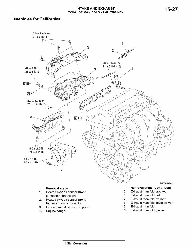
EXHAUST MANIFOLD <2.4L ENGINE>INTAKE AND EXHAUST 15-27
<Vehicles for California>
AC608497
49 ± 5 N·m36 ± 4 ft-lb
6
7
N
N
28 ± 8 N·m21 ± 6 ft-lb
4
41 ± 10 N·m30 ± 8 ft-lb
10N
9
3
8.0 ± 2.0 N·m71 ± 8 in-lb
8.0 ± 2.0 N·m71 ± 8 in-lb
8.0 ± 2.0 N·m71 ± 8 in-lb
8
5
2
1
AC
Removal steps 1. Heated oxygen sensor (front)
connector connection2. Heated oxygen sensor (front)
harness clamp connection3. Exhaust manifold cover (upper)4. Engine hanger
5. Exhaust manifold bracket6. Exhaust manifold nut7. Exhaust manifold washer8. Exhaust manifold cover (lower)9. Exhaust manifold10. Exhaust manifold gasket
Removal steps (Continued)
TSB Revision
EXHAUST PIPE, MAIN MUFFLER AND CATALYTIC CONVERTER <2.0L ENGINE>INTAKE AND EXHAUST15-28
INSPECTIONM1151003401375
.
EXHAUST MANIFOLD CHECK1. Check the exhaust manifold for damage and cracks, and
replace it if necessary.2. Using a straight edge and a thickness gauge, check for
distortion of the cylinder head installation surface. If it exceeds the limit value, replace it.
Limit: 0.70 mm (0.028 inch)
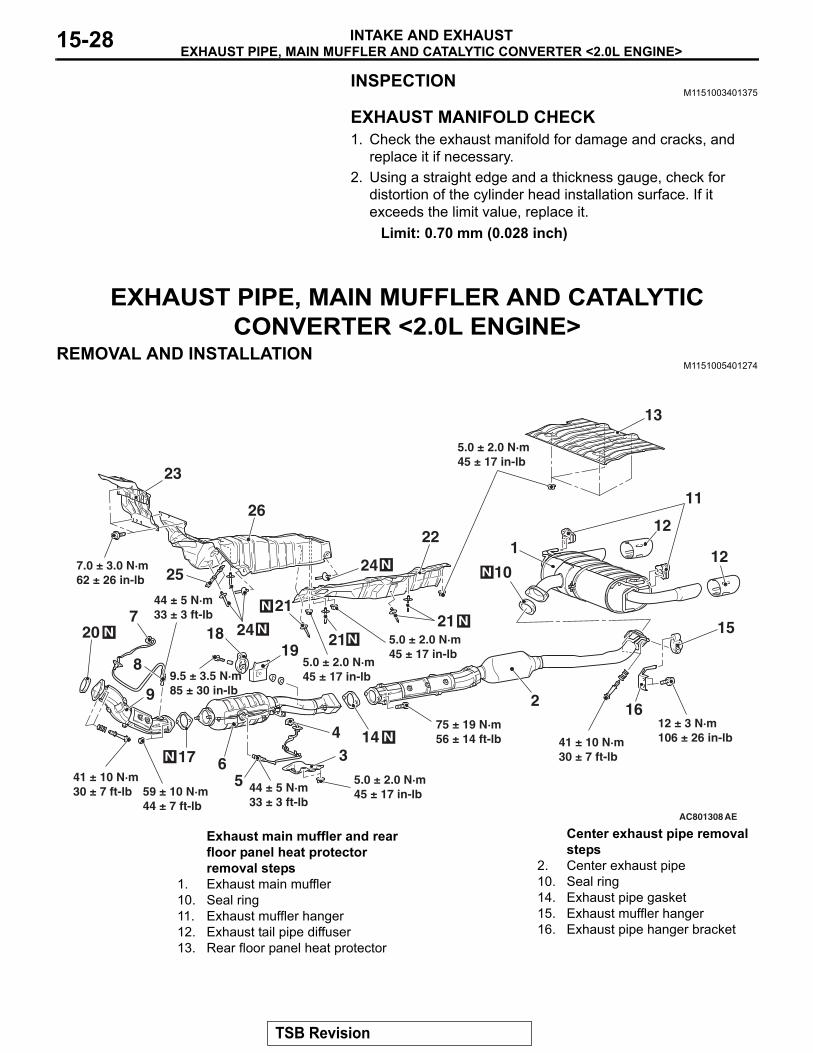
EXHAUST PIPE, MAIN MUFFLER AND CATALYTIC CONVERTER <2.0L ENGINE>
REMOVAL AND INSTALLATIONM1151005401274
AC801308
1
2
3
56
8
9
10N
11
12
12
13
14 N
15
17N
1819
20 N
4
7 21 N
21N
21N
22
24 N25
26
23
AE
16
41 ± 10 N·m30 ± 7 ft-lb
12 ± 3 N·m106 ± 26 in-lb
5.0 ± 2.0 N·m45 ± 17 in-lb
75 ± 19 N·m56 ± 14 ft-lb
5.0 ± 2.0 N·m45 ± 17 in-lb
5.0 ± 2.0 N·m45 ± 17 in-lb
5.0 ± 2.0 N·m45 ± 17 in-lb 44 ± 5 N·m
33 ± 3 ft-lb59 ± 10 N·m44 ± 7 ft-lb
41 ± 10 N·m30 ± 7 ft-lb
44 ± 5 N·m33 ± 3 ft-lb
7.0 ± 3.0 N·m62 ± 26 in-lb
9.5 ± 3.5 N·m85 ± 30 in-lb
24 N
Exhaust main muffler and rear floor panel heat protector removal steps
1. Exhaust main muffler10. Seal ring11. Exhaust muffler hanger12. Exhaust tail pipe diffuser13. Rear floor panel heat protector
Center exhaust pipe removal steps
2. Center exhaust pipe10. Seal ring14. Exhaust pipe gasket15. Exhaust muffler hanger16. Exhaust pipe hanger bracket
TSB Revision
EXHAUST PIPE, MAIN MUFFLER AND CATALYTIC CONVERTER <2.0L ENGINE>INTAKE AND EXHAUST 15-29
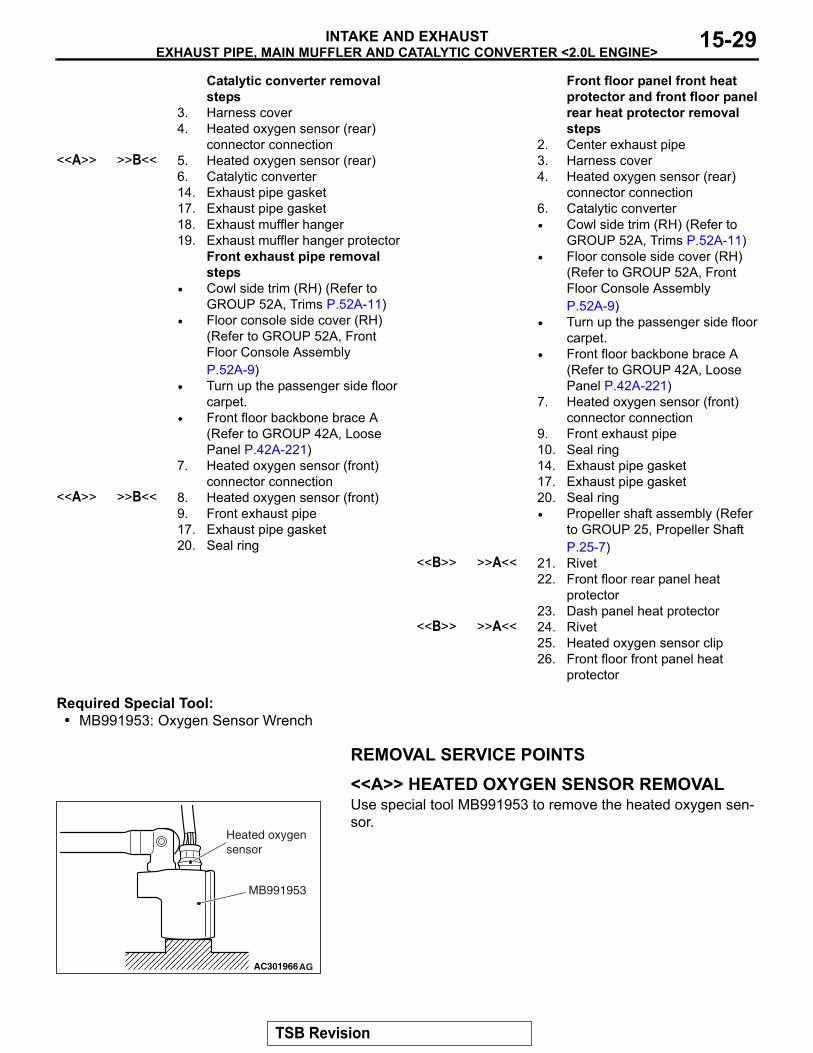
Required Special Tool:• MB991953: Oxygen Sensor Wrench
REMOVAL SERVICE POINTS.
<<A>> HEATED OXYGEN SENSOR REMOVALUse special tool MB991953 to remove the heated oxygen sen-sor.
.
Catalytic converter removal steps
3. Harness cover4. Heated oxygen sensor (rear)
connector connection<<A>> >>B<< 5. Heated oxygen sensor (rear)
6. Catalytic converter14. Exhaust pipe gasket17. Exhaust pipe gasket18. Exhaust muffler hanger19. Exhaust muffler hanger protector
Front exhaust pipe removal steps
• Cowl side trim (RH) (Refer to GROUP 52A, Trims P.52A-11)
• Floor console side cover (RH) (Refer to GROUP 52A, Front Floor Console Assembly P.52A-9)
• Turn up the passenger side floor carpet.
• Front floor backbone brace A (Refer to GROUP 42A, Loose Panel P.42A-221)
7. Heated oxygen sensor (front) connector connection
<<A>> >>B<< 8. Heated oxygen sensor (front)9. Front exhaust pipe17. Exhaust pipe gasket20. Seal ring
Front floor panel front heat protector and front floor panel rear heat protector removal steps
2. Center exhaust pipe3. Harness cover4. Heated oxygen sensor (rear)
connector connection6. Catalytic converter• Cowl side trim (RH) (Refer to
GROUP 52A, Trims P.52A-11)• Floor console side cover (RH)
(Refer to GROUP 52A, Front Floor Console Assembly P.52A-9)
• Turn up the passenger side floor carpet.
• Front floor backbone brace A (Refer to GROUP 42A, Loose Panel P.42A-221)
7. Heated oxygen sensor (front) connector connection
9. Front exhaust pipe10. Seal ring14. Exhaust pipe gasket17. Exhaust pipe gasket20. Seal ring• Propeller shaft assembly (Refer
to GROUP 25, Propeller Shaft P.25-7)
<<B>> >>A<< 21. Rivet22. Front floor rear panel heat
protector23. Dash panel heat protector
<<B>> >>A<< 24. Rivet25. Heated oxygen sensor clip26. Front floor front panel heat
protector
AC301966AG
MB991953
Heated oxygen sensor
TSB Revision
EXHAUST PIPE, MAIN MUFFLER AND CATALYTIC CONVERTER <2.0L ENGINE>INTAKE AND EXHAUST15-30
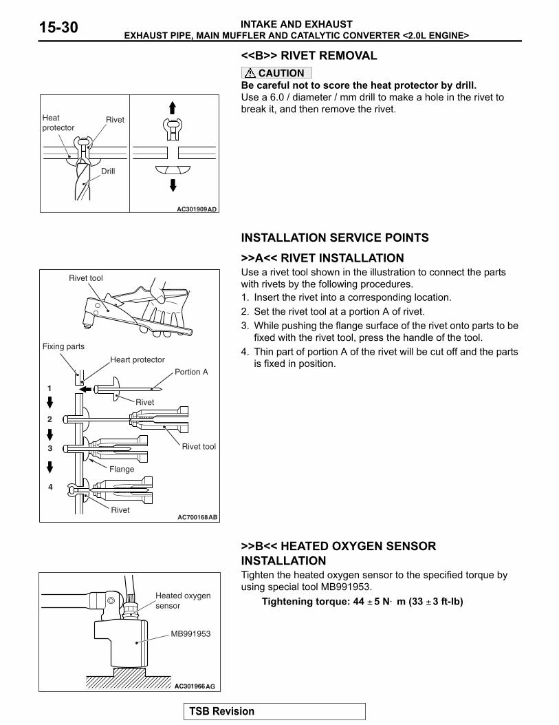
<<B>> RIVET REMOVALCAUTION
Be careful not to score the heat protector by drill.Use a 6.0 / diameter / mm drill to make a hole in the rivet to break it, and then remove the rivet.
INSTALLATION SERVICE POINTS.
>>A<< RIVET INSTALLATIONUse a rivet tool shown in the illustration to connect the parts with rivets by the following procedures.1. Insert the rivet into a corresponding location.2. Set the rivet tool at a portion A of rivet.3. While pushing the flange surface of the rivet onto parts to be
fixed with the rivet tool, press the handle of the tool.4. Thin part of portion A of the rivet will be cut off and the parts
is fixed in position.
.
>>B<< HEATED OXYGEN SENSOR INSTALLATIONTighten the heated oxygen sensor to the specified torque by using special tool MB991953.
Tightening torque: 44 ± 5 N⋅ m (33 ± 3 ft-lb)
AC301909AD
Heatprotector
Drill
Rivet
AC700168
Heart protector
Rivet tool
AB
1
2
3
4
Rivet
Fixing parts
Rivet tool
Rivet
Portion A
Flange
AC301966AG
MB991953
Heated oxygen sensor
TSB Revision
EXHAUST PIPE AND MAIN MUFFLER <2.4L ENGINE>INTAKE AND EXHAUST 15-31
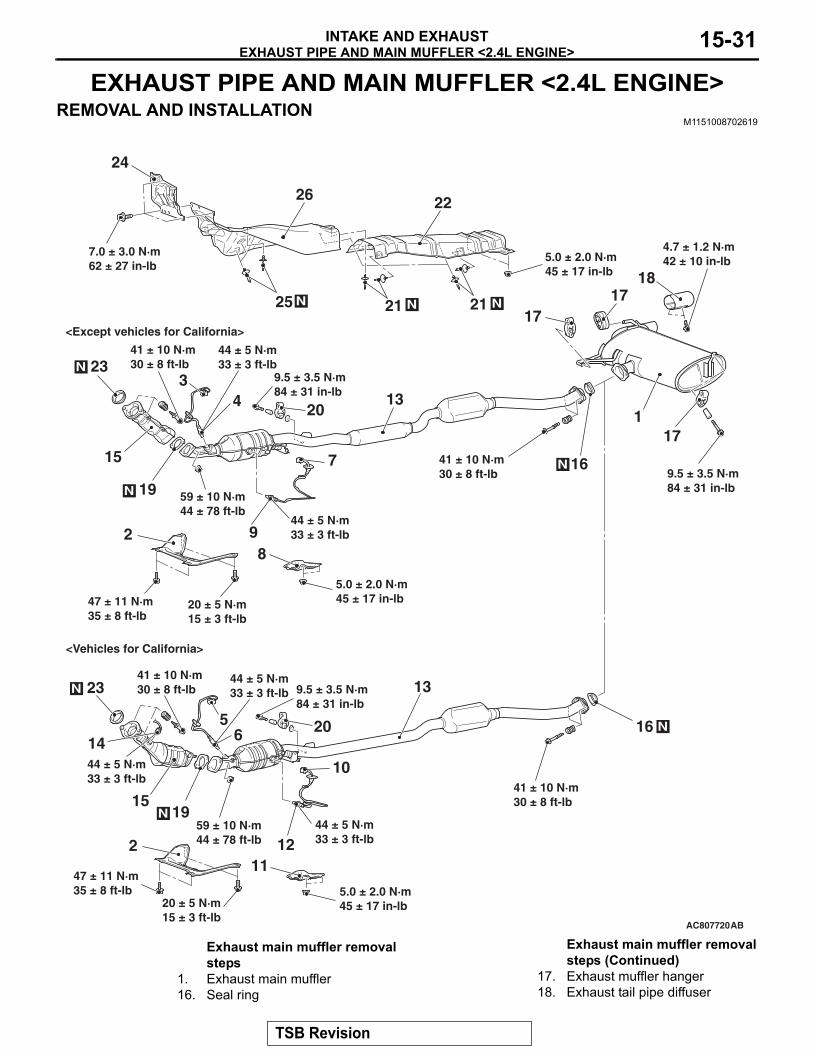
EXHAUST PIPE AND MAIN MUFFLER <2.4L ENGINE>REMOVAL AND INSTALLATION
M1151008702619
AC807720
<Except vehicles for California>
<Vehicles for California>
7.0 ± 3.0 N·m62 ± 27 in-lb
5.0 ± 2.0 N·m45 ± 17 in-lb
5.0 ± 2.0 N·m45 ± 17 in-lb
9.5 ± 3.5 N·m84 ± 31 in-lb
9.5 ± 3.5 N·m84 ± 31 in-lb
9.5 ± 3.5 N·m84 ± 31 in-lb
41 ± 10 N·m30 ± 8 ft-lb
41 ± 10 N·m30 ± 8 ft-lb
41 ± 10 N·m30 ± 8 ft-lb
41 ± 10 N·m30 ± 8 ft-lb
59 ± 10 N·m44 ± 78 ft-lb
59 ± 10 N·m44 ± 78 ft-lb
44 ± 5 N·m33 ± 3 ft-lb
44 ± 5 N·m33 ± 3 ft-lb
44 ± 5 N·m33 ± 3 ft-lb
44 ± 5 N·m33 ± 3 ft-lb
44 ± 5 N·m33 ± 3 ft-lb
47 ± 11 N·m35 ± 8 ft-lb
1
2
5
4
10
7
1112
9
13
13
14
15
15
16
16
1718
17
17
19
19
20
20
21 21
22
23
23
24
25
26
N
N
N
N
N N N
N
N6
3
20 ± 5 N·m15 ± 3 ft-lb
AB
4.7 ± 1.2 N·m42 ± 10 in-lb
5.0 ± 2.0 N·m45 ± 17 in-lb47 ± 11 N·m
35 ± 8 ft-lb
28
20 ± 5 N·m15 ± 3 ft-lb
Exhaust main muffler removal steps
1. Exhaust main muffler16. Seal ring
17. Exhaust muffler hanger18. Exhaust tail pipe diffuser
Exhaust main muffler removal steps (Continued)
TSB Revision
EXHAUST PIPE AND MAIN MUFFLER <2.4L ENGINE>INTAKE AND EXHAUST15-32
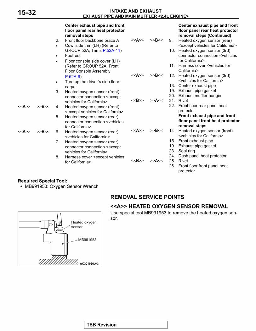
Required Special Tool:• MB991953: Oxygen Sensor Wrench
REMOVAL SERVICE POINTS.
<<A>> HEATED OXYGEN SENSOR REMOVALUse special tool MB991953 to remove the heated oxygen sen-sor.
.
Center exhaust pipe and front floor panel rear heat protector removal steps
2. Front floor backbone brace A• Cowl side trim (LH) (Refer to
GROUP 52A, Trims P.52A-11)• Footrest• Floor console side cover (LH)
(Refer to GROUP 52A, Front Floor Console Assembly P.52A-9)
• Turn up the driver’s side floor carpet.
3. Heated oxygen sensor (front) connector connection <except vehicles for California>
<<A>> >>B<< 4. Heated oxygen sensor (front) <except vehicles for California>
5. Heated oxygen sensor (rear) connector connection <vehicles for California>
<<A>> >>B<< 6. Heated oxygen sensor (rear) <vehicles for California>
7. Heated oxygen sensor (rear) connector connection <except vehicles for California>
8. Harness cover <except vehicles for California>
<<A>> >>B<< 9. Heated oxygen sensor (rear) <except vehicles for California>
10. Heated oxygen sensor (3rd) connector connection <vehicles for California>
11. Harness cover <vehicles for California>
<<A>> >>B<< 12. Heated oxygen sensor (3rd) <vehicles for California>
13. Center exhaust pipe19. Exhaust pipe gasket20. Exhaust muffler hanger
<<B>> >>A<< 21. Rivet22. Front floor rear panel heat
protectorFront exhaust pipe and front floor panel front heat protector removal steps
<<A>> >>B<< 14. Heated oxygen sensor (front) <vehicles for California>
15. Front exhaust pipe19. Exhaust pipe gasket23. Seal ring24. Dash panel heat protector
<<B>> >>A<< 25. Rivet26. Front floor front panel heat
protector
Center exhaust pipe and front floor panel rear heat protector removal steps (Continued)
AC301966AG
MB991953
Heated oxygen sensor
TSB Revision
EXHAUST PIPE AND MAIN MUFFLER <2.4L ENGINE>INTAKE AND EXHAUST 15-33
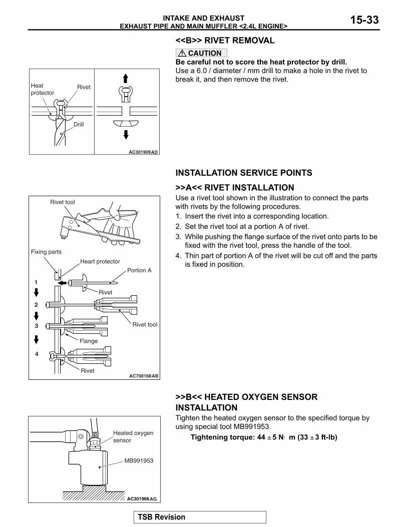
<<B>> RIVET REMOVALCAUTION
Be careful not to score the heat protector by drill.Use a 6.0 / diameter / mm drill to make a hole in the rivet to break it, and then remove the rivet.
INSTALLATION SERVICE POINTS.
>>A<< RIVET INSTALLATIONUse a rivet tool shown in the illustration to connect the parts with rivets by the following procedures.1. Insert the rivet into a corresponding location.2. Set the rivet tool at a portion A of rivet.3. While pushing the flange surface of the rivet onto parts to be
fixed with the rivet tool, press the handle of the tool.4. Thin part of portion A of the rivet will be cut off and the parts
is fixed in position.
.
>>B<< HEATED OXYGEN SENSOR INSTALLATIONTighten the heated oxygen sensor to the specified torque by using special tool MB991953.
Tightening torque: 44 ± 5 N⋅ m (33 ± 3 ft-lb)
AC301909AD
Heatprotector
Drill
Rivet
AC700168
Heart protector
Rivet tool
AB
1
2
3
4
Rivet
Fixing parts
Rivet tool
Rivet
Portion A
Flange
AC301966AG
MB991953
Heated oxygen sensor
TSB Revision

NOTES


![[Flip-Side] 4. Intake, Exhaust, Cylinder Flow](https://img.pdfslide.us/doc/110x75/56d6c06d1a28ab30169a58c8/flip-side-4-intake-exhaust-cylinder-flow.jpg)