Embed Size (px)
Citation preview

INITIAL LINE UP ROI-S05750
3-17
Chart 3-5 (Cont’d)
Step Procedure
ANTENNA DIRECTO MOUNTING TYPE
A. USING ANDREW VHLP TYPE BRACKET
Azimuth Angle Adjustment
6-1 Loosen bolts (1 in Fig. 3-4 (1/4) A),
6-2 Adjust the azimuth angle by adjusting bolt (2 in Fig. 3-4 (1/4) A),
6-3 Secure bolts loosened in step 6-1,
Elevation Angle Adjustment
6-4 Loosen bolts (3 in Fig. 3-4 (1/4) A),
6-5 Adjust the elevation angle by adjusting bolt (4 in Fig. 3-4 (1/4) A)
6-6 Secure bolts loosened in step 6-4,
B. USING RFS SB1 TYPE BRACKET
Azimuth Angle Adjustment
6-7 Loosen nuts (1 in Fig. 3-4-B),
6-8 Adjust the azimuth angle by adjusting the nuts (2 in Fig. 3-4 (1/4) B),
6-9 Secure nuts loosened in step 6-7,
Elevation Angle Adjustment
6-10 Loosen bolt(s) (3 in Fig. 3-4 (1/4) B),
6-11 Adjust the elevation angle by adjusting the nuts (4 in Fig. 3-4 (1/4) B),
6-12 Secure nut loosened in step 6-7,
6-13 Secure nuts loosened in step 6-10.

ROI-S05750 INITIAL LINE UP
3-18
Chart 3-5 (Cont’d)
Step Procedure
C. USING RFS C-Mount TYPE BRACKET
Azimuth Angle Adjustment
6-14 Loosen 3 bolts (1 in Fig. 3-4 (2/4)),
6-15 Adjust azimuth angle by adjusting bolt (2 in Fig. 3-4 (2/4)),
6-16 Secure nuts loosened in step 6-14,
Elevation Angle Adjustment
6-17 Loosen 4 bolts (3 in Fig. 3-4 (2/4)),
6-18 Adjust elevation angle by adjusting bolt (4 in Fig. 3-4 (2/4)),
6-19 Secure bolts loosened in step 6-17,
7 At each station, restore the “Antenna Alignment Mode” to “off” using the LCT,
8 At each station, reset control items to original using LCT,
9 At each station, restore the “MAINT Mode” to “off” position using the LCT,
10 At each station, disconnect the digital multimeter or NLite E Monitor from the RX LEV MON connector,
11 At each station, reconnect the cap removed in step 4,
Note: The RX LEV MON connector must be capped for waterproof.

INITIAL LINE UP ROI-S05750
3-19
Chart 3-5 (Cont’d)
Step Procedure
XPD Adjustment (For Antenna Directo Mounting Type)Note: The XPD adjustment using cross-polarization signal should be
done more carefully than using co-polarization signal because XPD changes sharply in the axial direction.
1’ Loosen three screws (SCREW1, 2 and 3 in Fig. 3-4 (3/4)) and rotate antenna (connected OMT/ODU) so that the RX LEVEL MON indicates the maximum value at the ODU of the Main Master and Sub Master channels,
2’ At opposite station, turns the ODU of the Sub Master channel power OFF (for both No.1 and No.2 Sub Master channels in 1+1 system),
3’ In this conditions, check the RX LEVEL MON indication value for XPD at the ODU of the Sub Master channel,
4’ Confirm that the XPD is more than 25 dB, if not, repeat Azimuth Angle, Elevation Angle and XPD Adjustment,
5’ At opposite station, turns the ODU of the Sub Master channel power ON,

1. Loosen for adjusting azimuth
2. Adjust azimuth
3. Loosen (1/4 TURN) bolts for adjusting elevation
0.3 φ m Antenna
B. RFS SB1 TYPE BRACKET
4. Adjust elevation
2. Adjust azimuth
1. Loosen (1/2 turn) bolts for adjusting azimuth (top and bottom)
3. Loosen (1/2 turn) bolts for adjusting elevation
4. Adjust elevation
A. ANDREW VHLP TYPE BRACKET
ROI-S05750 INITIAL LINE UP
3-20
Fig. 3-4 Location of Adjusting Nuts and Bolts (1/4)

1. Loosen (1/4 turn) bolts for adjusting azimuth
0.6 φ m Antenna
C. RFS C-Mount TYPE BRACKET
3. Loosen (1/4 turn) bolts for adjusting elevation.
2. Adjust azimuth.
4. Adjust elevation.
INITIAL LINE UP ROI-S05750
3-21
Fig. 3-4 Location of Adjusting Nuts and Bolts (2/4)

POLE
SCREW 2
SCREW 3
SCREW 1
ROTATIONINDICATOR
A. RFS SB1 TYPE BRACKET
B. RFS C-Mount TYPE BRACKET
ROI-S05750 INITIAL LINE UP
3-22
Fig. 3-4 Location of Adjusting Nuts and Bolts (3/4)

INITIAL LINE UP ROI-S05750
3-23
Chart 3-5 (Cont’d)
Step Procedure
WAVEGUIDE CONNECTION TYPE
Azimuth Angle Adjustment (Waveguide Connection Type)
Note: Take care that the flexible waveguide is not forcedly twisted by rotating the antenna.
When the HS/SD system is configured, alternately switchover the transmitter to the other channel (No.1 or No.2) at the opposite station and repeat adjustment of elevation and azimuth to obtain satisfactory results in both No.1 and No.2 CH. (Refer to Chart 3-8 for TX SW/RX SW Manual Switchover Operation).
1’ Loosen all strut attachment hardware,
2’ Loosen bolts indicated by arrows in Fig 3-4 (4/4)-A,
3’ Loosen jam nuts and rotate turnbuckle-1 in Fig 3-4 (4/4)-A so that the RX LEVEL MON voltage obtains the maximum value,
4’ Carefully, tighten turnbuckle-1 jam nuts and bolts indicated by arrows in Fig 3-4 (4/4)-A to hold the adjustment,
Elevation Angle Adjustment (Waveguide Connection Type)
5’ Make sure that all strut attachment hardware is loosened,
6’ Loosen bolts indicated by arrows in Fig 3-4 (4/4)-B,
7’ Loosen jam nuts and rotate turnbuckle-2 in Fig 3-4 (4/4)-B so that the RX LEVEL MON voltage obtains the maximum value,
8’ Carefully, tighten turnbuckle-2 jam nuts and bolts indicated by arrows in Fig 3-4 (4/4)-B,
XPD Adjustment (Waveguide Connection Type)
Note: This XPD adjustment using cross-polarization signal should be done more carefully than using co-polarization signal because XPD changes sharply in the axial direction.
9’ At opposite station, turns the ODU of the Sub Master channel power OFF (for both No.1 and No.2 Sub Master channels in 1+1 system),
10’ In this conditions, check the RX LEVEL MON indication value for XPD at the ODU of the Sub Master channel,
ROI-S05750 INITIAL LINE UP
3-24
Chart 3-5 (Cont’d)
Step Procedure
11’ Confirm that the XPD is more than 25 dB, if it is not obtained, repeat Azimuth Angle, Elevation Angle for the XPD Adjustment,
12’ Tighten all strut attachment hardware, turnbackle jam nuts and bolts indicated by arrows in Fig 3-4 (4/4) A and Fig 3-4 (4/4) B,
13’ At opposite station, turns the ODU of the Sub Master channel power ON (for both No.1 and No.2 slave channels in 1+1 system),
12 At each station, disconnect the digital multimeter or OW/RX LEV Monitor from the RX LEV MON connector,
13 At each station, reconnect the cap removed in step 4,
Note: The RX LEV MON connector must be capped for waterproof.
14 At each station, restore the “Antenna Alignment Mode” to “off” position using the LCT,
15 At the Main Master station, when the TX power control is operated in ATPC, restore the TX Power Control item of System Configuration changed in step 1 to “ATPC” using the LCT,
16 At the Main Master , when the TX power control is operated in MTPC, restore MTPC TX PWR item of “Provisioning Data” changed in step 2 to original setting valu using the LCT.
17 At each station, reset Maintenance to “OFF”.

STRUT TURNBUCKLE-1
A. Azimuth Adjustment
TURNBUCKLE-2
ANDREW VHLP4 TYPE BRACKET
B. Elevation Adjustment
INITIAL LINE UP ROI-S05750
3-25
Fig. 3-4 Location of Adjusting Nuts and Bolts (4/4)
INITIAL LINE UP ROI-S05750
3-27
3.5 Lineup Test
Lineup SONET NLite E test items between two stations are listed in Table 3-2.
Table 3-2 Lineup Test Items
Item Chart No.
Orderwire Test Chart 3-7
TX/RX SW Switchover Operation Chart 3-8 *1
DADE Adjust Chart 3-9 *2
BER Measurement Chart 3-10
Meter Reading Chart 3-11
PMON Clear Chart 3-12 *3
Note: *1 Chart 3-8 is described about Manual Switchover Operation.
*2 Chart 3-10 is needed only when INTFC is Out-phase in 1+1 configuration.
*3 After the intial lineup has been finished, clear PMON and RMON data for the start of service operation.
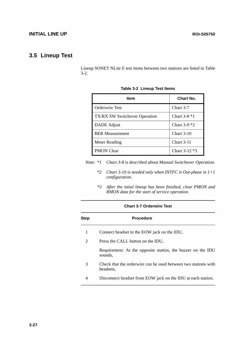
Chart 3-7 Orderwire Test
Step Procedure
1 Connect headset to the EOW jack on the IDU,
2 Press the CALL button on the IDU,
Requirement: At the opposite station, the buzzer on the IDU sounds,
3 Check that the orderwire can be used between two stations with headsets,
4 Disconnect headset from EOW jack on the IDU at each station.
AUX/ALMNMS NE SC IN/OUT EOW
PROTECT
CALL MMC
MAINTMEMORY
IDU
NLite E
LCT
EOW CALL
Local Station
AUX/ALMNMS NE SC IN/OUT EOW
PROTECT
CALL MMC
MAINTMEMORY
IDU
NLite E
LCT
EOW CALL
Opposite Station
ROI-S05750 INITIAL LINE UP
3-28
Fig. 3-5 OW Test Setup for IDU
INITIAL LINE UP ROI-S05750
3-29
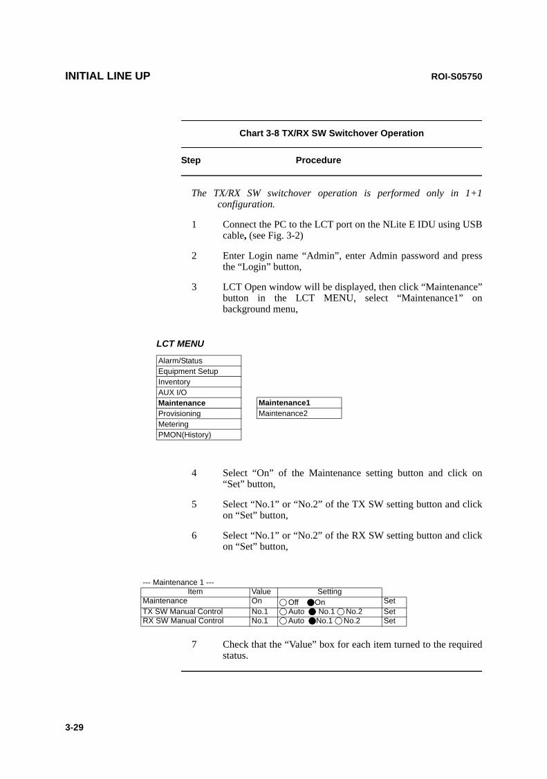
Chart 3-8 TX/RX SW Switchover Operation
Step Procedure
The TX/RX SW switchover operation is performed only in 1+1 configuration.
1 Connect the PC to the LCT port on the NLite E IDU using USB cable, (see Fig. 3-2)
2 Enter Login name “Admin”, enter Admin password and press the “Login” button,
3 LCT Open window will be displayed, then click “Maintenance” button in the LCT MENU, select “Maintenance1” on background menu,
LCT MENU
Alarm/StatusEquipment SetupInventoryAUX I/OMaintenanceProvisioningMeteringPMON(History)
Maintenance1Maintenance2
4 Select “On” of the Maintenance setting button and click on “Set” button,
5 Select “No.1” or “No.2” of the TX SW setting button and click on “Set” button,
6 Select “No.1” or “No.2” of the RX SW setting button and click on “Set” button,
--- Maintenance 1 ---Item Value Setting
Maintenance On Off On SetTX SW Manual Control No.1 Auto No.1 No.2 SetRX SW Manual Control No.1 Auto No.1 No.2 Set
7 Check that the “Value” box for each item turned to the required status.

ROI-S05750 INITIAL LINE UP
3-30
Chart 3-9 DADE Adjustment
Step Procedure
Note: The DADE control applies in 1+1 configuration to adjust delay time for RX hitless switching when the INTFC status is indicated Outphase.
1 Connect the USB cable to the USB port of PC and the LCT port of the IDU (see Fig. 3-2),
2 Login to LCT using Internet Explorer,
3 Enter Login name “Admin”, enter Admin password and press the “Login” button,
4 LCT Open window will be displayed, then click “Maintenance” button in the LCT Menu area, select “Maintenance1” on background menu,
5 Select “DADE Adjust” on the “Maintenance1” table,
---Maintenance1---Item Value SettingMaintenance On Off On SetDADE Adjust --- DADE Offset DADE DADE Off Set
6 Click on setting button “DADE”, “Off set DADE” or “DADE Off” and click on “Set” button,
Note: The DADE adjustment is needed in initial lineup or when the IF CABLE is replaced. It is not needed readjustment when the INTFC status is indicated In-phase. The setting conditions are as follows:DADE:Automatically adjust delay time based on either No.1 signal or No.2 signal
which it is selected by RX SW under the Outphase condition of the INTFC status. The DADE control is processed assuring no interruption of traffic.
Offset DADE:Automatically adjust delay time based on either No.1 signal or No.2 signal which it is selected by RX SW under the Outphase condition of the INTFC status. Since the offset memory minimizes the latency delay, traffic interruption occurs at that moment. This Offset DADE controls the delay time difference to a minimum than DADE control.
DADE off: Set when DADE function is not used. For particularly, when low bit rate (10 to 20 MB) transmission is applied to the system, the DADE control is not required.

INITIAL LINE UP ROI-S05750
3-31
Chart 3-10 BER Measurement
In 1+1 system, BER measurement of both No.1 and No.2 channels should be performed between terminal stations.
Apparatus :
Digital Multimeter with test leads
Screwdriver
SDH/SONET Analyzer
Optical Variable Attenuator
Headset
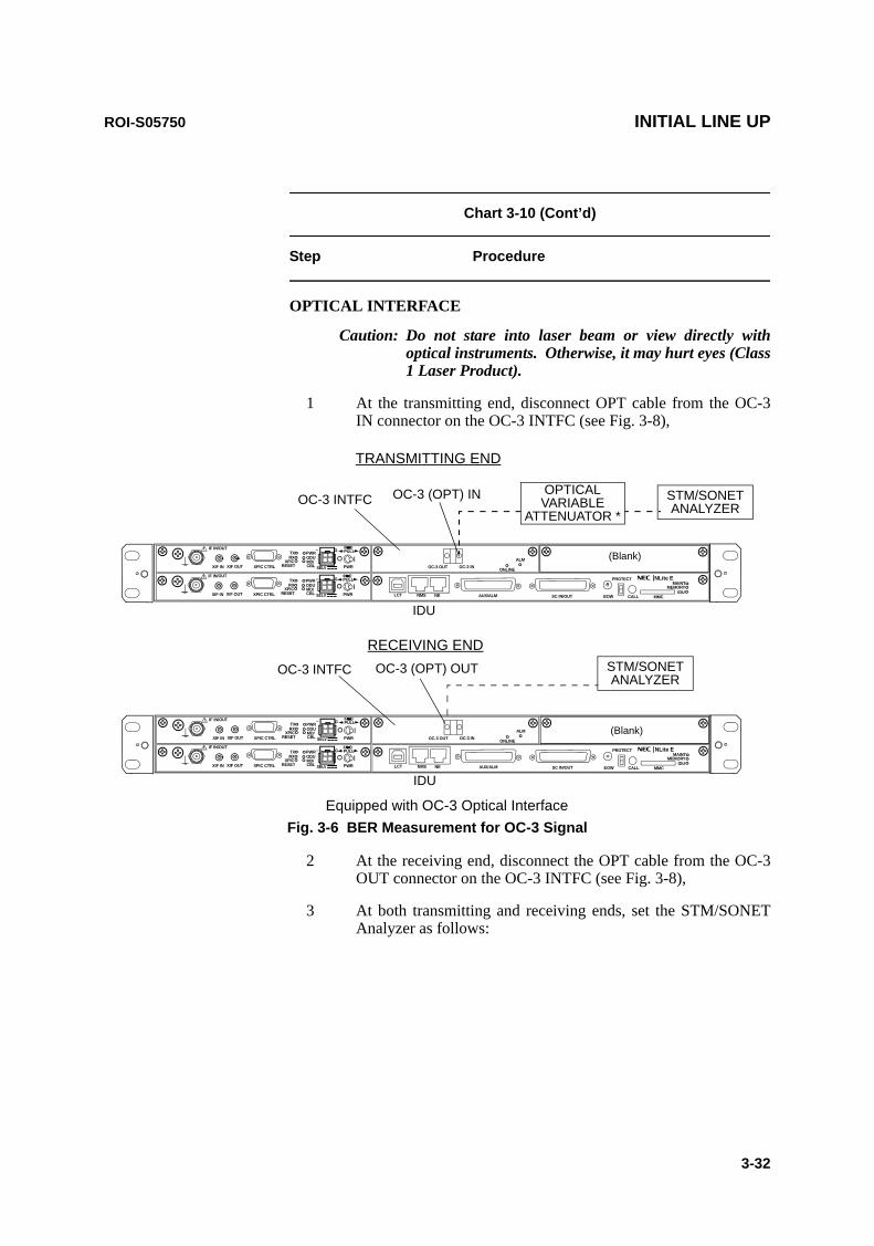
ROI-S05750 INITIAL LINE UP
3-32
Chart 3-10 (Cont’d)
Step Procedure
OPTICAL INTERFACE
Caution: Do not stare into laser beam or view directly with optical instruments. Otherwise, it may hurt eyes (Class 1 Laser Product).
1 At the transmitting end, disconnect OPT cable from the OC-3 IN connector on the OC-3 INTFC (see Fig. 3-8),
SELV
!
AUX/ALMNMS NE
ALM
SC IN/OUT EOW
PROTECT
CALL MMC
MAINTMEMORY
IDU
XIF IN XIF OUT
IF IN/OUTTXRX
RESETXPIC CTRLXPIC
PWRODUMD/CBL PWR
NLite E
LCT
OC-3 OUT OC-3 IN
PULL
SELV
!
XIF IN XIF OUT
IF IN/OUTTXRX
RESETXPIC CTRLXPIC
PWRODUMD/CBL PWR
PULL
ONLINE G
G
G
G
STM/SONETANALYZER
OC-3 INTFC
TRANSMITTING END
IDU
OC-3 (OPT) IN
STM/SONETANALYZER
OC-3 (OPT) OUT
OPTICAL VARIABLE
ATTENUATOR *
RECEIVING END
Equipped with OC-3 Optical Interface
IDU
SELV
!
AUX/ALMNMS NE
ALM
SC IN/OUT EOW
PROTECT
CALL MMC
MAINTMEMORY
IDU
XIF IN XIF OUT
IF IN/OUTTXRX
RESETXPIC CTRLXPIC
PWRODUMD/CBL PWR
NLite E
LCT
OC-3 OUT OC-3 IN
PULL
SELV
!
XIF IN XIF OUT
IF IN/OUTTXRX
RESETXPIC CTRLXPIC
PWRODUMD/CBL PWR
PULL
ONLINE G
G
G
G
(Blank)
(Blank)
OC-3 INTFC
Fig. 3-6 BER Measurement for OC-3 Signal
2 At the receiving end, disconnect the OPT cable from the OC-3 OUT connector on the OC-3 INTFC (see Fig. 3-8),
3 At both transmitting and receiving ends, set the STM/SONET Analyzer as follows:
INITIAL LINE UP ROI-S05750
3-33
Chart 3-10 (Cont’d)
Step Procedure
OC-3 INTFC(OPTICAL) • Bit rate : 155.52 Mbps• Code format : OC-3, NRZ• Level S-1.1 L-1.1
IN : −8 to −28 dBm/ −10 to −34 dBm OUT : −8 to −15 dBm/ 0 to −8 dBm
• Wave lengthIN : 1310 nmOUT : 1310 nm
Note: Operation of the TX SW and RX SW are not required in 1+0 system.
4 In HS system, set the TX SW to No.1 or No.2 to On condition at transmitting end, (refer to Chart 3-8)
5 At receiving end, set the RX SW to either No.1 or No.2 to On condition,
6 Measure BER and confirm that the values are indicated as follows:Requirement: 1 x 10–12 or less
7 At receiving end, change setting of the RX SW to opposite No.1 or No.2 from it in step 5 and confirm that the measured value satisfies requirement given in step 6,
8 Change setting of the TX SW to opposite No.1 or No.2 from it in step 4 and confirm that the measured value satisfies requirement given in step 6,
9 At receiving end, change setting of the RX SW to opposite No.1 or No.2 from it in step 7 and confirm that the measured value satisfies requirement given in step 6,
10 Restore all connections and controls to normal.
ROI-S05750 INITIAL LINE UP
3-34
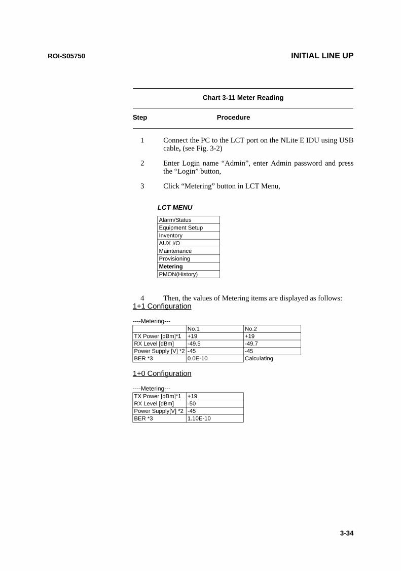
Chart 3-11 Meter Reading
Step Procedure
1 Connect the PC to the LCT port on the NLite E IDU using USB cable, (see Fig. 3-2)
2 Enter Login name “Admin”, enter Admin password and press the “Login” button,
3 Click “Metering” button in LCT Menu,
LCT MENU
Alarm/StatusEquipment SetupInventoryAUX I/OMaintenanceProvisioningMeteringPMON(History)
4 Then, the values of Metering items are displayed as follows: 1+1 Configuration
----Metering---No.1 No.2
TX Power [dBm]*1 +19 +19RX Level [dBm] -49.5 -49.7Power Supply [V] *2 -45 -45BER *3 0.0E-10 Calculating
1+0 Configuration
----Metering---TX Power [dBm]*1 +19RX Level [dBm] -50Power Supply[V] *2 -45BER *3 1.10E-10

INITIAL LINE UP ROI-S05750
3-35
Chart 3-11 (Cont’d)
Step Procedure
Notes: *1:TX POWER Level is indicated in 1 dB step. The TX Power varies depending on the propagation condition within setup ATPC range in provisioning, therefore, TX Power may be displayed within limited values listed in Table 3-3. Add attenuation value for Max. and Min. level when additional attenuator is used.
*2:Power supply voltage of the ODU input varies depending on the IF cable length.
*3: During total number of erroneous bits and total number of correctly received bits are calculating, “Calculating” and *E-** are displayed.
Table 3-3 TX Power Output Level
ModulationMode Frequency Band (GHz) 6 7-8 10-11 13 15 18 23 26 28 32 38 52
32QAM Output Power Max. (dBm) (at ATPC 0 dB)
+25 +21 +19 +18 +17 +14.5 -
Output Power Min. (dBm) +2 (−3) −2 (−7) −4 (−9) −5 (−10) −5 −6 −6.5 -
Additional attenuator (dB) 5 NA
128QAM Output Power Max. (dBm) (at ATPC 0 dB)
+25 +21 +19 +18 +17 +14.5 -
Output Power Min. (dBm) +5(0) +1(−4) −1(−6) −2 (−7) −2 −3 −5.5 -
Additional attenuator (dB) 5 NA
Tolerance (dB) +/−3 (except additional attenuator)
Note: ( ) shows the values with additional attenuator.
ROI-S05750 INITIAL LINE UP
3-36
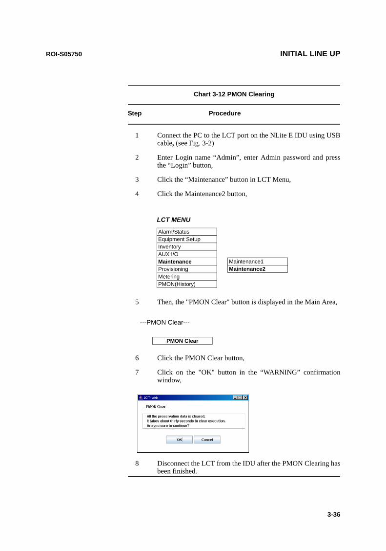
Chart 3-12 PMON Clearing
Step Procedure
1 Connect the PC to the LCT port on the NLite E IDU using USB cable, (see Fig. 3-2)
2 Enter Login name “Admin”, enter Admin password and press the “Login” button,
3 Click the “Maintenance” button in LCT Menu,
4 Click the Maintenance2 button,
LCT MENU
Alarm/StatusEquipment SetupInventoryAUX I/OMaintenanceProvisioningMeteringPMON(History)
Maintenance1Maintenance2
5 Then, the "PMON Clear" button is displayed in the Main Area,
---PMON Clear---
PMON Clear
6 Click the PMON Clear button,
7 Click on the "OK" button in the “WARNING” confirmation window,
8 Disconnect the LCT from the IDU after the PMON Clearing has been finished.

ROI-S05752-05DE CONTENTS August, 2007
CL-1
NLite E 6-38 GHz SONET DIGITAL RADIO SYSTEM
Section IV APPENDIX
NLite E LCT OPERATION
CONTENTS
TITLE PAGE
1 Introduction •••••••••••••••••••••••••••••••••••••••••••••••••••••••••• 11.1 Accessing the NLITE E •••••••••••••••••••••••••••••••••••••••• 21.2 LCT MENU Items •••••••••••••••••••••••••••••••••••••••••••••• 111.3 Alarm/Status (SONET) ••••••••••••••••••••••••••••••••••••••• 131.4 Equipment Setup (SONET) ••••••••••••••••••••••••••••••••• 192 Inventory •••••••••••••••••••••••••••••••••••••••••••••••••••••••••••• 253 AUX. I/O ••••••••••••••••••••••••••••••••••••••••••••••••••••••••••••• 274 Maintenance------------------------------------------------------------ 284.1 Maintenance1(SONET) •••••••••••••••••••••••••••••••••••••• 294.2 Maintenance2•••••••••••••••••••••••••••••••••••••••••••••••••• 365 Provisioning •••••••••••••••••••••••••••••••••••••••••••••••••••••••• 435.1 Provisioning Setup (SONET)---------------------------------- 446 Metering•••••••••••••••••••••••••••••••••••••••••••••••••••••••••••••• 566.1 PMON (SONET)•••••••••••••••••••••••••••••••••••••••••••••••• 586.1.1 PMON (History)•••••••••••••••••••••••••••••••••••••••••••• 58
6.1.2 RMON (History) ••••••••••••••••••••••••••••••••••••••••••• 61
7 Installation of USB •••••••••••••••••••••••••••••••••••••••••••••••• 638 Dial-up Setting ••••••••••••••••••••••••••••••••••••••••••••••••••••• 669 Java Runtime Install •••••••••••••••••••••••••••••••••••••••••••••• 7510 LCTWEB (Version 2) Install••••••••••••••••••••••••••••••••••••• 76
ROI-S05752 Introduction
-1-
1. Introduction
This Local Craft Terminal (LCT) Operation Manual describe how to setup, manage, monitor and controls NLITE E SONET microwave radio systems.
User should prepare the computer (PC), USB cable and necessary peripheral device used for equipment setup.
The following hardware and software for the PC are recommended. Use the latest updated version of the software.
Hardware requirement• HD: 100 MB or higher free capacity• RAM: 512 MB• Display: LCD 1,024 × 768• CD-ROM drive• Serial port• USB port• USB cable with USB-B connector
Software requirement (English version)
• OS: Windows 2000/Xp
• IE6.0 SP2 (LCTWEB Applet Version 1 (Rev.1.xx.xx))
• Java Runtime Environment: V1.5.0_05 is applied. (Refer to Chapter 12 for Java 2 Runtime installation.) It is required for the LCTWEB Applet Rev.2.01.xxx or former version. It is not required for the LCTWEB Applet Rev.2.03.xxx or later version.

Introduction ROI-S05752
-2-
1.1 Accessing the NLITE E
There are two types LCT version corresponded to the IDU F/W version. Check the LCT type indicated on the LCT CD-ROM before connecting the PC to the IDU. The LCTWEB Pallet Version 1 (Rev.1.xx.xx) is installed into the IDU and the LCTWEB Applet Version 2 (Rev. 2.xx.xx) is installed into the PC as follows.
PC (LCT)
NLITE E
PC (LCT)
CD-ROM
LCTWEB Applet IDU PC CD-ROM
Version 1: Rev.1.xx.xx (IDU preinstalled)
CTRL F/W Version 2: Rev.2.x.x - PMC - SMU - LCT WEB Applet
- USB Driver - Java Runtime
Type 001 Version 1.0 LCT WEB Setup Files - USB Driver - Java Runtime
Version 2: Rev.2.xx.xx (Installation from CD-ROM to PC)
CTRL F/W Version 3: Rev. 3.x.x - PMC - SMU
- USB Driver - Java Runtime - LCT WEB Applet (Rev. 2.01.xxx or former)
Type 002 Version 2.x LCT WEB Setup Files - USB Driver - Java Runtime - LCT WEB Applet (Rev. 2.01.xxx or former)
- USB Driver - LCT WEB Applet (Rev. 2.03.xxx or later)
Type 002 Version 2.x LCT WEB Setup Files - USB Driver - LCT WEB Applet (Rev. 2.03.xxx or later)
LCT-WEB Applet(Pre-Installed)
USB DriverJava Runtime
USB DriverJava Runtime
LCT-WEB Setup File
LCT Ver.1.xx
USB DriverJava Runtime
USB DriverJava Runtime
LCT-WEB Setup File
LCT-WEB AppletLCT-WEB Applet
NLITE E IDULCT Ver.2.xx
LCT WEB APPLET (Rev.2.01.xxx or former version)
SELV
!
AUX/ALMNMS NE
ALM
SC IN/OUT EOW
PROTECT
CALL MMC
MAINTMEMORY
IDU
XIF IN XIF OUT
IF IN/OUTTXRX
RESETXPIC CTRLXPIC
PWRODUMD/CBL PWR
NLite E NEO
LCT
OC-3 INOC-3 OUT
PULL
ALM
OC-3 INOC-3 OUT
(Blank)
ONLINEONLINE GG
G
SELV
!
AUX/ALMNMS NE
ALM
SC IN/OUT EOW
PROTECT
CALL MMC
MAINTMEMORY
IDU
XIF IN XIF OUT
IF IN/OUTTXRX
RESETXPIC CTRLXPIC
PWRODUMD/CBL PWR
NLite E NEO
LCT
OC-3 OUT OC-3 IN
PULL
SELV
!
XIF IN XIF OUT
IF IN/OUTTXRX
RESETXPIC CTRLXPIC
PWRODUMD/CBL PWR
PULL
ALMOC-3 OUT OC-3 INONLINE ONLINE G
G
G
G

ROI-S05752 Introduction
-3-
1 Connect the Computer (PC) with a USB cable between the LCT port and the USB port,
Notes: 1. Install the USB modem driver, Java 2 Run Time Module, LctWeb Run Time (for LCT Ver.2 IDU) and create the dial-up connection before trying to connect the LCT. For the details, refer to Chapter 10 to Chapter 13.
2. USB modem driver should be installed first before creating the dial-up connection.
3. The Java 2 Run Time installation is not required when the LCTWEB Applet Rev.2.03.xxx or later version is used.
NLITE E IDU
USB Driver USB DriverLCT-WEB Setup File
LCT Ver.2.xx
LCT-WEB AppletLCT-WEB Applet
Note : For the later version of the LCT WEB Applet Rev. 2.03.xxx, the LCT WEB Applet includes . Runtime.
LCT WEB APPLET (Rev.2.03.xxx or later version)
LCT-WEB Applet
Java
SELV
!
AUX/ALMNMS NE
ALM
SC IN/OUT EOW
PROTECT
CALL MMC
MAINTMEMORY
IDU
XIF IN XIF OUT
IF IN/OUTTXRX
RESETXPIC CTRLXPIC
PWRODUMD/CBL PWR
NLite E NEO
LCT
OC-3 OUT OC-3 IN
PULL
SELV
!
XIF IN XIF OUT
IF IN/OUTTXRX
RESETXPIC CTRLXPIC
PWRODUMD/CBL PWR
PULL
ALMOC-3 OUT OC-3 INONLINE ONLINE G
G
G
G
USB Cable
PC for LCT
USB port
NLITE E IDU
LCT NMS NE
NLite E NEO ODU
LCT port
LCT SETUP
SELV
!
AUX/ALMNMS NE
ALM
SC IN/OUT EOW
PROTECT
CALL MMC
MAINTMEMORY
IDU
XIF IN XIF OUT
IF IN/OUTTXRX
RESETXPIC CTRLXPIC
PWRODUMD/CBL PWR
NLite E NEO
LCT
OC-3 INOC-3 OUT
PULL
ALM
OC-3 INOC-3 OUT
(Blank)
ONLINEONLINE G
G
G

Introduction ROI-S05752
-4-
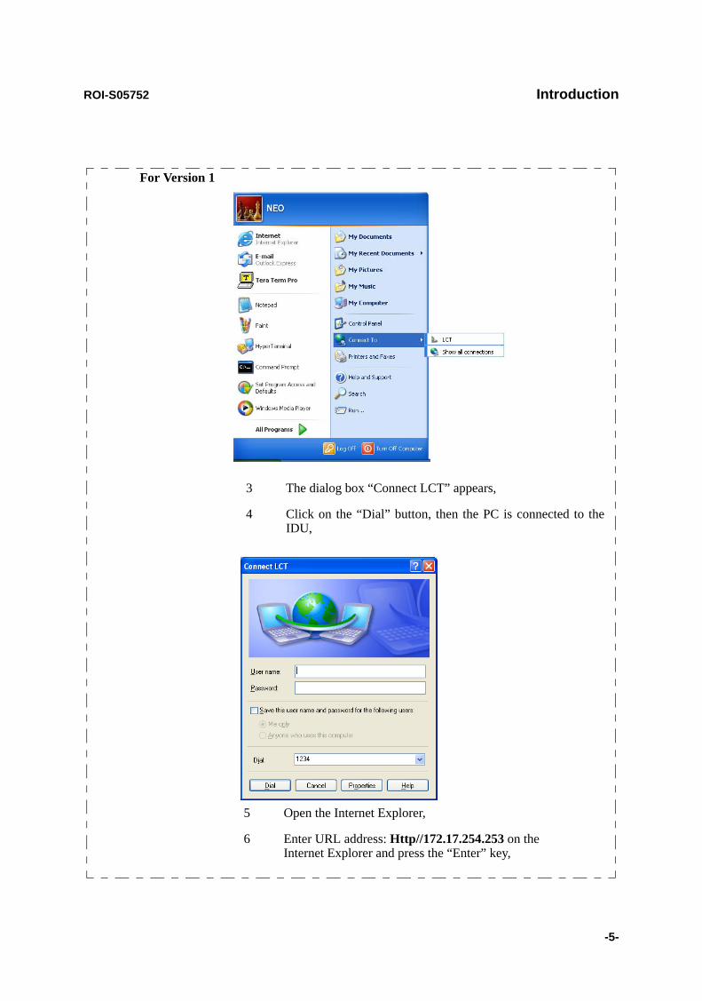
2 Click on the “START” menu button, select “Connect to”, “LCT”, then, “Connect LCT” dial-up dialog is appeared,
Note: When type of the LCTWEB and the F/W of the IDU differs, following “ERROR” alert appears.
ROI-S05752 Introduction
-5-
For Version 1
3 The dialog box “Connect LCT” appears,
4 Click on the “Dial” button, then the PC is connected to the IDU,
5 Open the Internet Explorer,
6 Enter URL address: Http//172.17.254.253 on the Internet Explorer and press the “Enter” key,
Introduction ROI-S05752
-6-
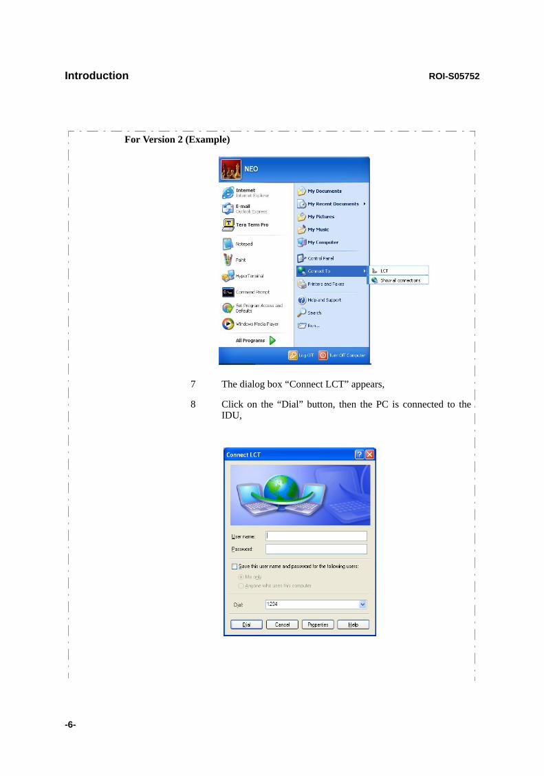
For Version 2 (Example)
7 The dialog box “Connect LCT” appears,
8 Click on the “Dial” button, then the PC is connected to the IDU,

ROI-S05752 Introduction
-7-
Note: When type of the LCTWEB (ver. 2.xx) is applied for the F/W (ver. 2.xx) of the IDU, “ERROR Wrong LCT Type; terminal cannot connect to IDU” alert appears. In that case, start the Internet Explorer and enter URL address: Http//172.17.254.253 on the Internet Explorer and press the “Enter” key.
When type of the LCTWEB (ver. 2.xx) is applied for the F/W (ver. 3.xx) of the IDU, double click on the short-cut icon or select the“Programs” → “NEC_ LCT” → “LCT For STD” from the “start” menu as mentioned above.
10 Enter User ID and password in User/Password entry fields and press the “Login” button,
9 Double click on the short-cut icon or select the “Programs” → “NEC_ LCT” → “LCT For STD” from the “start” menu,
Introduction ROI-S05752
-8-
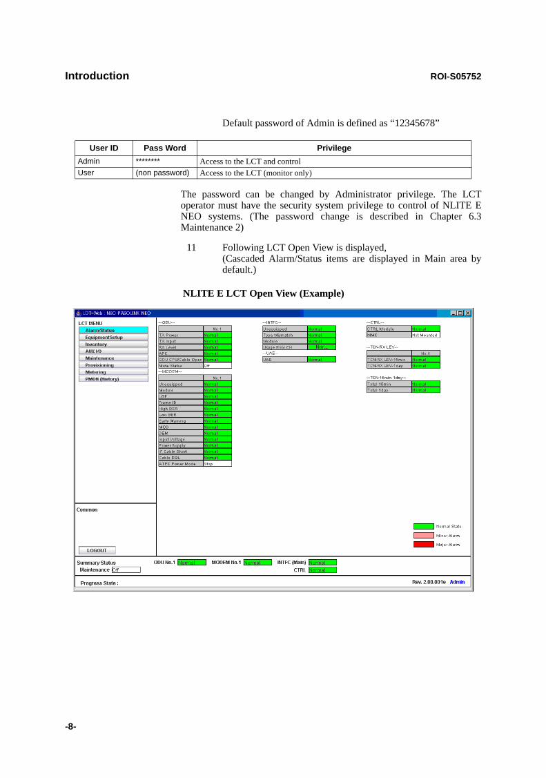
Default password of Admin is defined as “12345678”
The password can be changed by Administrator privilege. The LCT operator must have the security system privilege to control of NLITE E NEO systems. (The password change is described in Chapter 6.3 Maintenance 2)
11 Following LCT Open View is displayed, (Cascaded Alarm/Status items are displayed in Main area by default.)
User ID Pass Word PrivilegeAdmin ******** Access to the LCT and controlUser (non password) Access to the LCT (monitor only)
NLITE E LCT Open View (Example)

ROI-S05752 Introduction
-9-
Symbols in the Open View are described as follows.
Description of the LCT MENU Conventions
LCT MENU
“SET” button appears/disappears depending on the Menu item selected in the “LCT MENU”.
Main area
Menu area
Common area
Alarm StatusEquipment SetupInventoryAUX I/OMaintenanceProvisioningMeteringPMON(History)
LCT MENU
Maintenance ON
Summary Status areaProgress State area
Title
LOGOUT
Common
Progress State:
CloseMaximizeMinimize
Title bar
Summary Status
ODU No.1 Normal MODEM No.1
MODEM No.2ODU No.2 Normal
Normal
Normal
INTFC(Main)
CTRL
Normal
Normal
INTFC(Sub)
Admin
SET
Normal StateMinor AlarmMajor Alarm
Criteria
LCT MENU SETAlarm/Status disappearEquipment Setup appearInventory disappearAUX I/O appearMaintenance disappearProvisioning appearMetering disappearPMON (History) disappear

Introduction ROI-S05752
-10-
Summary Status Area
Following summary items show the operating status.
Note: When the ODU No. 2, MODEM No. 2 or INTFC (Sub) is not mounted, corresponding item is colored gray. INTFC (Main)/INTFC (Sub) are changed to INTFC (WORK)/INTFC(PROT) in APS system.
Progress State Area
Following Response is displayed. When “Set” button is clicked.
Execute all the changes made in the items shown in the main area by the selected “LCT MENU”. Displays confirmation box to Logout. Clicking LOG OUT button, the LCT-Web screen is logged out and the Login screen is displayed. Reload recent data to display.
Common
SET
LOGOUT
RELOAD
For 1+1 Configuration For 1+0 Configuration
Item Status Indication Item Status IndicationMaintenance On (yellow) Off (white) Maintenance On (yellow) Off (white)
ODU No.1 Normal (green) Alarm (red) ODU Normal (green) Alarm (red)
ODU No.2 Normal (green) Alarm (red) IDU Normal (green) Alarm (red)
MODEM No.1 Normal (green) Alarm (red)MODEM No.2 Normal (green) Alarm (red)INTFC (Main) Normal (green) Alarm (red)INTFC (Sub) Normal (green) Alarm (red)CTRL Normal (green) Alarm (red)
SET Control Response
OK - Response OKNG - Response NG
: Menu Button displays pull-down menu
: No Selected
: Selected
Set : Execute control/setup for each item
Symbol;

ROI-S05752 Introduction
-11-
1.2 LCT MENU Items
LCT MENU is consisted of the following table.
LCT MENU SUB-MENU REMARKS
Alarm/Status Refer to “2. Alarm/Status”Equipment Setup Refer to “3. Equipment Setup”Inventory Refer to “2. Inventory”AUX I/O Refer to “3. AUX. I/O”Maintenance Refer to “4. Maintenance”
Maintenance1Maintenance2
Provisioning Refer to “5. Provisioning”XC Setting *6BER Threshold SettingSUB Interface For SONET onlySC AssignmentLAN Port SettingOC-3 Setting For SONET onlyMS-AIS generation For SONET onlyALS Function *1TX Power ControlCondition for TX/RX SW *2Condition for APS *3Relay SettingTCN Threshold(15min)TCN Threshold(1day)PMON SelectOthers
Metering Refer to “6. Metering”

Introduction ROI-S05752
-12-
Notes:*1 Only provides for SONET OC-3 OPT interface.*2 Only provides for 1+1 configuration.*3 Only provides for APS in SONET for OC-3 OPT interface.*4 Only provides for LAN.*
PMON (History) Refer to “9. PMON”RX Level(24H/15min)RX Level(7days/day)Total(24H/15min) *4Total(7days/day) *4RMON(Line)(24H/15min) *5RMON(Line)(7days/day) *5RMON(DMR)(24H/15min) *5RMON(DMR)(7days/day) *5DMR(W)(7days/day) For SONET onlyDMR(W)(24H/15min) For SONET onlyDMR(P)(7days/day) *3DMR(P)(24H/15min) *3MUX(W)(7days/day) For SONET onlyMUX(W)(24H/15min) For SONET onlyMUX(P)(7days/day) *3MUX(P)(24H/15min) *3
LCT MENU SUB-MENU REMARKS

ROI-S05752 Introduction
-13-
1.3 Alarm Status (SONET)
When click on the “Alarm Status” button in “LCT MENU”, following items/status (sample) are displayed in Main Area.
ALM items of SONET are listed in Table 2-2.
Alarm/Status items are displayed in Main area in default when accessing the LCT.
Note: Alarm/Status indication varies depending on the system configuration.
Notes: Item (*1) is displayed in XPIC configuration only. Item (*2) is displayed in Hot Standby configuration only. Item (*3) is displayed in Hot Standby and Twinpath configuration.
Note: Item (*1) is displayed in XPIC configuration only.
---ODU---Item Status
No.1 No. 2TX Power Normal Normal TX Input Normal Normal RX Level Normal Normal APC Normal Normal ODU CPU/Cable Open Normal Normal Mute Status OFF OFFLO REF Normal Normal (*1)TX SW Status No.1 (*2)RX SW Status No.2 (*3)
---MODEM---Item Status
No.1 No. 2Unequipped Normal Normal Module Normal Normal LOF Normal Normal Frame ID Normal Normal High BER Normal Normal Low BER Normal Normal Early Warning Normal Normal MOD Normal Normal DEM Normal Normal Input Voltage Normal Normal Power Supply Normal Normal IF Cable Short Normal Normal Cable EQL Normal Normal XIF Normal Normal (*1)XPIC Status Normal Normal (*1)XREF Normal Normal (*1)Linearizer Function OPR NON OPR Linearizer Normal NormalATPC Power Mode Active Active

Introduction ROI-S05752
-14-
Notes: Item (*1) is displayed in APS configuration only. Item (*2) is displayed in XPIC configuration only.
Note: Item (*1) is displayed in Main LAN configuration only. Click on the corresponding item in status block, following details LAN PORT status in the LAN/WS INTFC appears.
Link: Displaying LINK status for respective Port.Collision: Displaying occurrence of Collision status in Half Duplex mode for respective
Port.LLF: Forced LINK off control status detecting the link loss of the facing
equipment for respective Port.Speed &Duplex:Displaying linked mode for respective Port.
---CTRL---Item Status
CTRL Module NormalMMC Mount Not MountedAPS SW Fail Normal (*1)APS Online Status Working (*1)APS Lock in Status Normal (*1)XCTRL Normal (*2)XPIC Mode Mismatch Normal (*2)
---INTFC (Main) (1)---Item Status
MainUnequipped Normal Type Mismatch Normal Module Normal LOS(MUX) Normal LOF(MUX) Normal E-BER(MUX) Normal SD(MUX) Normal LOS(DMR) Normal LOF(DMR) Normal E-BER(DMR) Normal SD(DMR) Normal LAN LINK Normal (*1)Speed & Duplex Normal (*1)Inphase Inphase TF Normal Output Control Normal
Item Status
Link Collision LLF Speed&DuplexMain PORT1 Link Normal Normal 10M-Half(MDI)Main PORT2 Link Normal Normal 10M-Half(MDIX)
Close
ROI-S05752 Introduction
-15-
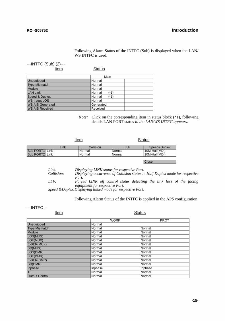
Following Alarm Status of the INTFC (Sub) is displayed when the LAN/WS INTFC is used.
Note: Click on the corresponding item in status block (*1), following details LAN PORT status in the LAN/WS INTFC appears.
Link: Displaying LINK status for respective Port.Collision: Displaying occurrence of Collision status in Half Duplex mode for respective
Port.LLF: Forced LINK off control status detecting the link loss of the facing
equipment for respective Port.Speed &Duplex:Displaying linked mode for respective Port.
Following Alarm Status of the INTFC is applied in the APS configuration.
---INTFC (Sub) (2)---Item Status
MainUnequipped Normal Type Mismatch Normal Module Normal LAN Link Normal (*1)Speed & Duplex Normal (*1)WS In/out LOS Normal WS AIS Generated GeneratedWS AIS Received Received
Item Status
Link Collision LLF Speed&DuplexSub PORT1 Link Normal Normal 10M-Half(MDI)Sub PORT2 Link Normal Normal 10M-Half(MDI)
Close
---INTFC---Item Status
WORK PROTUnequipped Normal Type Mismatch Normal Normal Module Normal Normal LOS(MUX) Normal Normal LOF(MUX) Normal Normal E-BER(MUX) Normal Normal SD(MUX) Normal Normal LOS(DMR) Normal Normal LOF(DMR) Normal Normal E-BER(DMR) Normal Normal SD(DMR) Normal Normal Inphase Inphase Inphase TF Normal Normal Output Control Normal Normal

Introduction ROI-S05752
-16-
Notes: OFS:Out of Frame SecondUAS:Unavailable SecondES:Errored SecondSES:Severely Errored SecondBBE:Background Block ErrorSEP:Severely Errored Period
---UAE---Item Status
WORK PROTOC-3(1) UAE(MUX) Normal Normal OC-3(2) UAE(MUX) Normal Normal OC-3(1) UAE(DMR) Normal Normal OC-3(2) UAE(DMR) Normal Normal
---TCN RX LEV---Item Status
No.1 No.2 TCN-RX LEV-15min Normal Normal TCN-RX LEV-1day Normal Normal
Item Status
---15min 1day --- WORK PROTTCN-OFS-15min (DMR) Normal Normal TCN-UAS-15min (DMR) Normal Normal TCN-ES-15min (DMR) Normal Normal TCN-SES-15min (DMR) Normal Normal TCN-BBE-15min (DMR) Normal Normal TCN-SEP-15min (DMR) Normal Normal TCN-OFS-15min(MUX) Normal Normal TCN-UAS-15min(MUX) Normal Normal TCN-ES-15min(MUX) Normal Normal TCN-SES-15min(MUX) Normal Normal TCN-BBE-15min(MUX) Normal Normal TCN-SEP-15min(MUX) Normal Normal TCN-OFS-1day (DMR) Normal Normal TCN-UAS-1day (DMR) Normal Normal TCN-ES-1day (DMR) Normal Normal TCN-SES-1day (DMR) Normal Normal TCN-BBE-1day (DMR) Normal Normal TCN-SEP-1day (DMR) Normal Normal TCN-OFS-1day(MUX) Normal Normal TCN-UAS-1day(MUX) Normal Normal TCN-ES-1day(MUX) Normal Normal TCN-SES-1day(MUX) Normal Normal TCN-BBE-1day(MUX) Normal Normal TCN-SEP-1day(MUX) Normal Normal

ROI-S05752 Introduction
-17-
Table 1-1 ALM/STATUS List (SONET) (1/2)
No. ALM/STATUS ITEM EVENT STATUS SOURCE OF EVENT
Configuration CriteriaDefault1+0 1+1
1 ODU CPU/Cable Open ALM1 ODU1 CPU failure or IF Cable is open ODU No.1 Major2 ODU CPU/Cable Open ALM2 ODU2 CPU failure or IF Cable is open ODU No.2 *1 Major3 ODU ALM1 ODU1 total alarm ODU No.1 Major4 ODU ALM2 ODU2 total alarm ODU No.2 *1 Major5 TX PWR ALM1 ODU1 output power decreased ODU No.1 Major6 TX PWR ALM2 ODU2 output power decreased ODU No.2 *1 Major7 TX INPUT ALM1 ODU1 TX IF input level decreased ODU No.1 Major8 TX INPUT ALM2 ODU2 TX IF input level decreased ODU No.2 *1 Major9 APC ALM1 ODU1 LO OSC APC loop out of lock ODU No.1 Major10 APC ALM2 ODU2 LO OSC APC loop out of lock ODU No.2 *1 Major11 RX LEVEL ALM1 ODU1 Received level decreased ODU No.1 Major12 RX LEVEL ALM2 ODU2 Received level decreased ODU No.2 *1 Major13 IF CABLE SHORT ALM1 IF cable connected to ODU1short MODEM No.1 Major14 IF CABLE SHORT ALM2 IF cable connected to ODU2 short MODEM No.2 *1 Major15 MUTE STATUS1 ODU1 Mute Status ODU No.1 Status16 MUTE STATUS2 ODU2 Mute Status ODU No.2 *1 Status17 LO REF ALM1 ODU1 LO reference signal is lost ODU No.1 *2 Minor18 LO REF ALM2 ODU2 LO reference signal is lost ODU No.2 *1,*2 *2 Minor19 IDU ALM IDU total alarm CTRL Major20 IDU CPU ALM IDU CPU failure CTRL *1,*3 *3 Major22 MEMORY ALM MMC memory error CTRL Major23 ATPC PWR MODE1 No.1 ATPC failure, Hold/Maximum/Minimum*5 poweroutput CTRL Status24 ATPC PWR MODE2 No.2 ATPC failure, Hold//MaximumMinimum*5 poweroutput CTRL *1 Status25 PS ALM1 No.1 power supply failure (only1+1) MODEM No.1 Major26 PS ALM2 No.2 power supply failure (only1+1) MODEM No.2 *1 Major27 MOD ALM1 PLL APC unlock, output level down, CLK loss in MODEM1 MODEM No.1 Major28 MOD ALM2 PLL APC unlock, output level down, CLK loss in MODEM2 MODEM No.2 *1 Major29 DEM ALM1 Carrier/Frame Asynchronous at MODEM1 MODEM No.1 Major30 DEM ALM2 Carrier/Frame Asynchronous at MODEM2 MODEM No.2 *1 Major33 EARLY WARNING1 EARLY WARNING is detected in No.1 CH MODEM No.1 *1 Status34 EARLY WARNING2 EARLY WARNING is detected in No.2 CH MODEM No.2 *1 Status35 HIGH BER ALM1 High BER (selectable) is detected in MODEM1 MODEM No.1 Major36 HIGH BER ALM2 High BER (selectable) is detected inMODEM2 MODEM No.2 *1 Major37 LOW BER ALM1 Low BER (selectable) is detected in MODEM1 MODEM No.1 Minor38 LOW BER ALM2 Low BER (selectable) is detected in MODEM2 MODEM No.2 *1 Minor39 LOF1 Loss of Radio frame synchronization in MODEM1 MODEM No.1 Major40 LOF2 Loss of Radio frame synchronization in MODEM2 MODEM No.2 *1 Major41 FRAME ID ALM1 ID is no coincidence in MODEM1 MODEM No.142 FRAME ID ALM2 ID is no coincidence in MODEM2 MODEM No.2 *143 CABLE EQL FAIL1 Cable EQL control is lost in MODEM1 MODEM No.1 Major44 CABLE EQL FAIL2 Cable EQL control is lost in MODEM2 MODEM No.2 *1 Major45 LINEARIZER FAIL1 BB LNZ control is lost in MODEM1 ODU No.1 Major46 LINEARIZER FAIL2 BB LNZ control is lost in MODEM1 ODU No.2 *1 Major47 XPIC STATUS1 No. 1 XPIC function is off MODEM No.1 *2 Status48 XPIC STATUS2 No. 2 XPIC function is off MODEM No.2 *1,*2 *2 Status49 XCTRL ALM1 No. 1 XPIC control failure MODEM No.1 *2 Major50 XCTRL ALM2 No. 2 XPIC control failure MODEM No.2 *2 Major51 XIF ALM1 No. 1 XIF signal is lost MODEM No.1 *2 Major52 XIF ALM2 No. 2 XIF signal is lost MODEM No.2 *1,*2 *2 Major53 XREF ALM1 No. 1 XPIC reference CLK is lost MODEM No.1 *2 Minor54 XREF ALM2 No. 2 XPIC reference CLK is lost MODEM No.2 *1,*2 *2 Minor55 INTFC(1) INPAHSE Main INTFC inphase status INTFC *1 Status56 INTFC(2) INPAHSE Prot INTFC inphase status OC-3 INTFC P *1 Status63 OC-3(1) UAE No. 1 OC-3 INTFC UAS is generating OC-3 INTFC W Status64 OC-3(2) UAE No. 2 OC-3 INTFC UAS is generating OC-3 INTFC P *1 Status65 OC-3(1) LOS(MUX) No. 1 OC-3 from MUX, loss of signal is detected OC-3 INTFC Major

Introduction ROI-S05752
-18-
Notes: *1. Not applied.*2. XPIC configuration only.*3. Not displayed on LCT.*4. APS configuration only.*5. Selectable.*6. LAN configuration only.
66 OC-3(2) LOS(MUX) No. 2 OC-3 from MUX, loss of signal is detected OC-3 INTFC *1 Major67 OC-3(1) LOF(MUX) No. 1 OC-3 from MUX, loss of frame is detected OC-3 INTFC Major68 OC-3(2) LOF(MUX) No. 2 OC-3 from MUX, loss of frame is detected OC-3 INTFC *1 Major69 OC-3(1) LOS(DMR) No. 1 OC-3 from DMR, loss of signal is detected OC-3 INTFC Major70 OC-3(2) LOS(DMR) No. 2 OC-3 from DMR, loss of signal is detected OC-3 INTFC Major71 OC-3(1) LOF(DMR) No. 1 OC-3 from DMR, loss of frame is detected OC-3 INTFC Major72 OC-3(2) LOF(DMR) No. 2 OC-3 from DMR, loss of frame is detected OC-3 INTFC *1 Major73 OC-3(1) E-BER(MUX) No. 1 OC-3 from MUX, Excessive-BER is detected OC-3 INTFC Major74 OC-3(2) E-BER(MUX) No. 2 OC-3 from MUX, Excessive-BER is detected OC-3 INTFC Major75 OC-3(1) SD(MUX) No. 1 OC-3 from MUX, Signal Degrade is detected OC-3 INTFC Major76 OC-3(2) SD(MUX) No. 2 OC-3 from MUX, Signal Degrade is detected OC-3 INTFC Major77 OC-3(1) E-BER(DMR) No. 1 OC-3 from DMR, Excessive-BER is detected OC-3 INTFC Major78 OC-3(2) E-BER(DMR) No. 2 OC-3 from DMR, Excessive-BER is detected OC-3 INTFC Major79 OC-3(1) SD(DMR) No. 1 OC-3 from DMR, Signal Degrade is detected OC-3 INTFC Major80 OC-3(2) SD(DMR) No. 2 OC-3 from DMR, Signal Degrade is detected OC-3 INTFC Major81 OC-3(1) TF ALM No. 1 OC-3 output to MUX is failure OC-3 INTFC Major82 OC-3(2) TF ALM No. 2 OC-3 output to MUX is failure OC-3 INTFC Major83 APS SW FAIL APS switch is failure CTRL *4 Major84 LAN LINK LAN LINK status Main INTFC *6 Major85 LAN COLLISION LAN status Main INTFC *6 Status86 LAN LLF ALM LAN Link Loss Forwarding status Main INTFC *6 Status87 SPEED & DUPLEX LAN Port setting Main INTFC *6 Status88 WS INPUT LOSS WS Input signal is lost Main INTFC *6 Minor89 WS AIS RCVD WS AIS signal is received Main INTFC *6 Status90 WS AIS GENERATED WS AIS signal is generated Main INTFC *6 Status95 MODEM ALM1 MODEM1 total alarm MODEM Major96 MODEM ALM2 MODEM2 total alarm MODEM *1 Major97 INTFC(1) ALM Main INTFC total alarm OC-3 INTFC Major98 INTFC(2) ALM Main INTF Sub INTFC OC-3 INTFC/
SUB INTFCMajor
99 CTRL ALM CTRL UNIT total alarm CTRL Major100 MODEM 1 UNEQUIP MODEM1 is unequipped CTRL Major101 MODEM 2 UNEQUIP MODEM2 is unequipped CTRL Major102 INTFC(1) UNEQUIP MAIN INTFC is unequipped CTRL Major103 INTFC(2) UNEQUIP SUB INTFC is unequipped CTRL Minor104 INPUT VOLTAGE ALM1 PS1 input over voltage/lower voltage MODEM No.1 Major105 INPUT VOLTAGE ALM2 PS2 input over voltage/lower voltage MODEM No.2 *1 Major106 INTFC (1) TYPE MISSMATCH Mounted INTFC differs from configuration setting Main INTFC Major107 INTFC (2) TYPE MISSMATCH Mounted INTFC differs from configuration setting Main INTFC Major108 OC-3 (1) OUTPUT CONTROL MS-AIS control for MUX Main INTFC *5 Status109 OC-3 (2) OUTPUT CONTROL MS-AIS control for MUX Main INTFC *5 Status110 OC-3 (1) APS LOCKIN STATUS APS is in lockin Main INTFC *4 Status111 OC-3 (2) APS LOCKIN STATUS APS is in lockin Main INTFC *4 Status
Table 1-1 ALM/STATUS List (SONET) (2/2)
No. ALM/STATUS ITEM EVENT STATUS SOURCE OF EVENT
Configuration CriteriaDefault1+0 1+1
ROI-S05752 Introduction
-19-
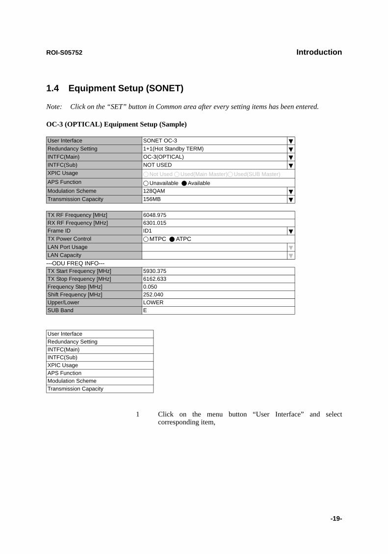
1.4 Equipment Setup (SONET)
Note: Click on the “SET” button in Common area after every setting items has been entered.
OC-3 (OPTICAL) Equipment Setup (Sample)
1 Click on the menu button “User Interface” and select corresponding item,
User Interface SONET OC-3Redundancy Setting 1+1(Hot Standby TERM) INTFC(Main) OC-3(OPTICAL)INTFC(Sub) NOT USEDXPIC Usage Not Used Used(Main Master) Used(SUB Master)APS Function Unavailable AvailableModulation Scheme 128QAMTransmission Capacity 156MB
TX RF Frequency [MHz] 6048.975RX RF Frequency [MHz] 6301.015Frame ID ID1TX Power Control MTPC ATPCLAN Port UsageLAN Capacity---ODU FREQ INFO---TX Start Frequency [MHz] 5930.375TX Stop Frequency [MHz] 6162.633Frequency Step [MHz] 0.050Shift Frequency [MHz] 252.040Upper/Lower LOWER SUB Band E
User Interface Redundancy Setting INTFC(Main) INTFC(Sub) XPIC Usage APS Function Modulation SchemeTransmission Capacity

Introduction ROI-S05752
-20-
User Interface
2 Click on the menu button “Redundancy Setting” and select corresponding item,
The “User Interface” item selected decides the selectable items that follows.
3 Setup can be performed by clicking on menu button to select setup item from pull-down menu, clicking setting button or entering values, then click on the “SET” button in Common area to complete and confirm the setup procedure.
For the XPIC Usage, set Main Master and Sub Master in the XPIC configuration. Set to Not Used in other configurations. In the XPIC, define the IDU for the Main Master and Sub Master channels, they must be connected to one dual polarized antenna. The reference local frequency and the action control of the ATPC/MTPC are applied from the Main Master channel to the Sub Master
User Interface SONET OC-3SONET GbE OC-3
Redundancy Setting
Redundancy Setting 1+0(TERM)1+1(Hot Standby TERM)1+1(Twinpath TERM)
INTFC(Main) (*)
INTFC(Main) OC-3(Optical) (*)GbE over OC-3
INTFC(Sub) (*)
INTFC(Sub) Not Used (*)OC-3 (Optical)LAN
Note: Select OC-3 OPT for APS, when APS to be configured to the system.
XPIC Usage
XPIC Usage Not UsedUsed (Main Master)Used (Sub Master)
Note: When XPIC is configured to the system, polarization for Main Master/Sub Muster must not be setup crossed between two stations.

ROI-S05752 Introduction
-21-
channel.
(*) INTFC(Main)/INTFC(Sub) are changed to INTFC (WORK)/INTFC(PROT) in APS system.
RF Frequency
Notes: 1 Set different values for No.1 TX frequency and No.2 TX frequency in the Twinpath configuration.
2 Depending on the ODU type, there are two modes for the RF frequency setup.
1. When the transmitting frequency is set, the receiving frequency is automatically assigned.
2. When the transmitting frequency is set, the receiving frequency is automatically assigned and assignment of it in manual is also available by changing the RX RF frequency values which is automatically assigned.
3 The transmitting frequency for the Main Master and Sub Master must be set the same and also the receiving frequency. The frequency setup must be performed at the Main Master station first and then, Sub Master station.
The entered TX RF frequency value should be within the Start and Stop frequency range of Sub-Band which is indicated on the Name Plate of each ODU. For details, refer to the Appendix RADIO FREQUENCY PLAN OF THE NLITE E NEO in Section 1.
Caution: For the 6/7/8/10 GHz band, the BPF of TX and RX of the ODU are adjusted to each assigned frequency. Then, to change the RF channel frequency, both BPFs replacement and LCT setup are required.
TX Frequency and RF Frequency for No.1 and No.2 are displayed in Twinpath configuration.
APS Function Unavailable Available
TX RF Frequency(No.1) [MHz]TX RF Frequency(No.2) [MHz]RX RF Frequency(No.1) [MHz]RX RF Frequency(No.2) [MHz]
Introduction ROI-S05752
-22-
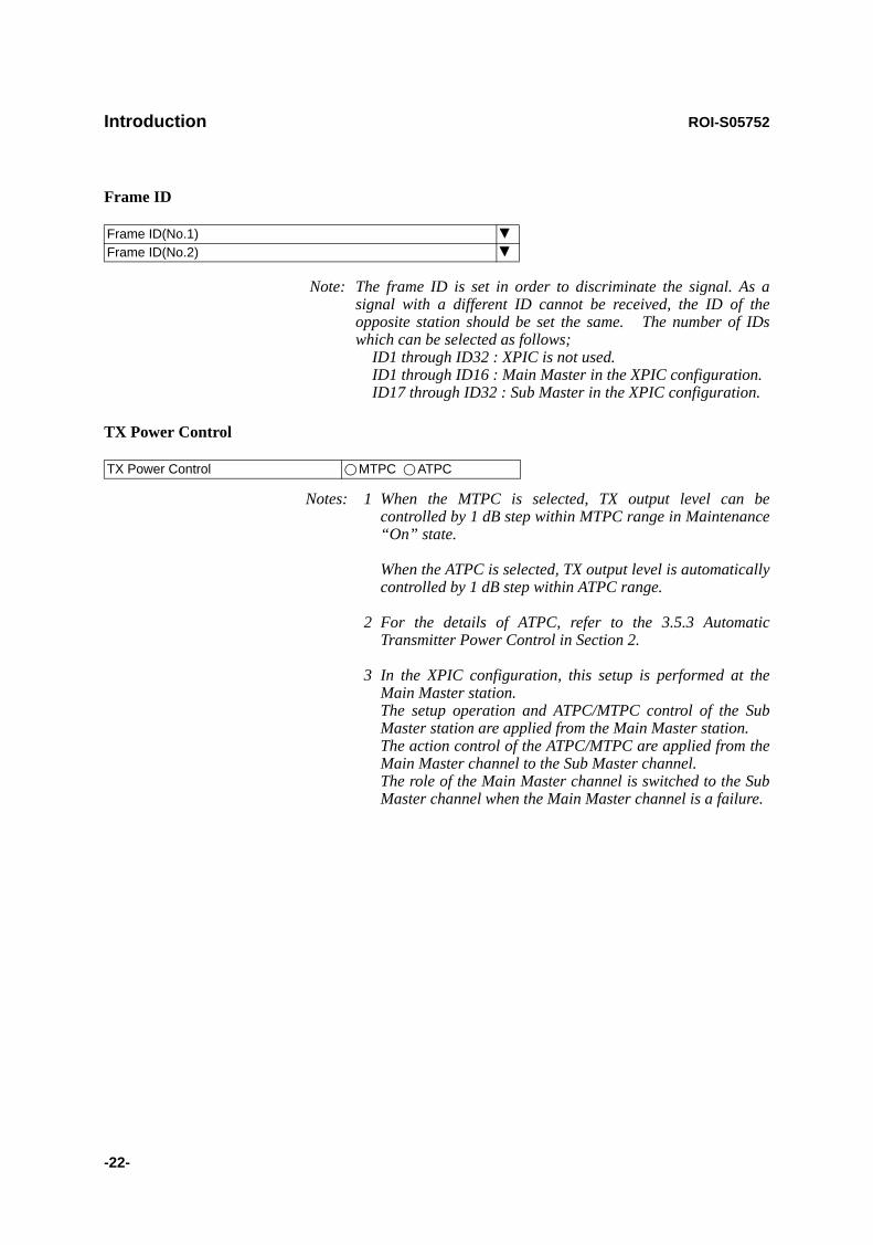
Frame ID
Note: The frame ID is set in order to discriminate the signal. As a signal with a different ID cannot be received, the ID of the opposite station should be set the same. The number of IDs which can be selected as follows;
ID1 through ID32 : XPIC is not used. ID1 through ID16 : Main Master in the XPIC configuration. ID17 through ID32 : Sub Master in the XPIC configuration.
TX Power Control
Notes: 1 When the MTPC is selected, TX output level can be controlled by 1 dB step within MTPC range in Maintenance “On” state.
When the ATPC is selected, TX output level is automatically controlled by 1 dB step within ATPC range.
2 For the details of ATPC, refer to the 3.5.3 Automatic Transmitter Power Control in Section 2.
3 In the XPIC configuration, this setup is performed at the Main Master station. The setup operation and ATPC/MTPC control of the Sub Master station are applied from the Main Master station. The action control of the ATPC/MTPC are applied from the Main Master channel to the Sub Master channel. The role of the Main Master channel is switched to the Sub Master channel when the Main Master channel is a failure.
Frame ID(No.1)Frame ID(No.2)
TX Power Control MTPC ATPC

ROI-S05752 Introduction
-23-
LAN Port Usage (Main)
For GbE INTFC
Note: When the GbE INTFC is applied, LAN Port Usage (MAIN) is fixed to "USED" and also LAN Port Capacity (MAIN) is to 150Mbps.
For LAN/WS INTFC
Note: Select "SONET over OC-3" from User Interface in the Equipment Setup, LAN over OC-3 is assigned for the INTFC Main.
1. LAN Port Usage (MAIN): Setting for radio transmission band in each port.P1=75MB/P2=75MB (default) P1=100MB/P2=50MB Best Effort P1=100MB/P2=Not Used
2. LAN Capacity (MAIN): The LAN capacity is fixed to 150MB.
Notes: 1. LAN Capacity may be set when WS/LAN is used.2. Selectable LAN capacity is depending on the main
signal transmission capacity. 64kbps: SC and RSOH E1/F1 are usable. 128kbps: SC1-2 are usable. 192kbps: RSOH DCCr is usable. 256kbps: SC1-4 are usable. 2Mbitps: When LAN is used.
4 Click on the “SET” button in a Common area to execute setup.
LAN Port Usage (MAIN) USEDLAN Port Capacity (MAIN) 150Mbps
LAN Port Usage (MAIN) P1=75MB/P2=75MBP1=100MB/P2=50MBBest EffortP1=100MB/P2=Not Used
LAN Port Capacity (MAIN) 150Mbps
LAN Port Usage (SUB) P1-2 Shared/1Port Only(WS)P1-2 Shared/1Port Only(SC)
LAN Capacity (SUB) 64kbps128kbps192kbps256kbps2Mbps
Introduction ROI-S05752
-24-
5 Click on the “SET” button in Common area, then “OK” is displayed in Progress area when the setup is properly executed.
Note: “NG” and error message are displayed in Progress State area, if there is invalid setting in the Equipment Setup.
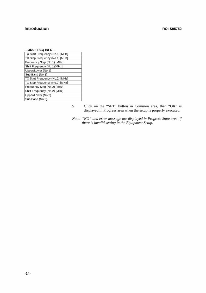
---ODU FREQ INFO---TX Start Frequency (No.1) [MHz]TX Stop Frequency (No.1) [MHz]Frequency Step (No.1) [MHz]Shift Frequency (No.1)[MHz]Upper/Lower (No.1)Sub Band (No.1)TX Start Frequency (No.2) [MHz]TX Stop Frequency (No.2) [MHz]Frequency Step (No.2) [MHz]Shift Frequency (No.2) [MHz]Upper/Lower (No.2)Sub Band (No.2)
ROI-S05752 Inventory
-25-
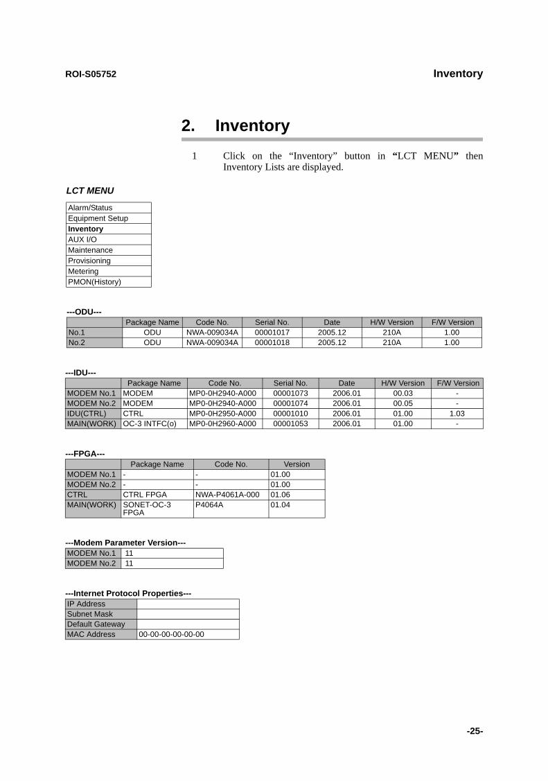
2. Inventory1 Click on the “Inventory” button in “LCT MENU” then
Inventory Lists are displayed.
---ODU---Package Name Code No. Serial No. Date H/W Version F/W Version
No.1 ODU NWA-009034A 00001017 2005.12 210A 1.00No.2 ODU NWA-009034A 00001018 2005.12 210A 1.00
---IDU---Package Name Code No. Serial No. Date H/W Version F/W Version
MODEM No.1 MODEM MP0-0H2940-A000 00001073 2006.01 00.03 -MODEM No.2 MODEM MP0-0H2940-A000 00001074 2006.01 00.05 -IDU(CTRL) CTRL MP0-0H2950-A000 00001010 2006.01 01.00 1.03MAIN(WORK) OC-3 INTFC(o) MP0-0H2960-A000 00001053 2006.01 01.00 -
---FPGA---Package Name Code No. Version
MODEM No.1 - - 01.00MODEM No.2 - - 01.00CTRL CTRL FPGA NWA-P4061A-000 01.06MAIN(WORK) SONET-OC-3
FPGAP4064A 01.04
---Modem Parameter Version---MODEM No.1 11MODEM No.2 11
---Internet Protocol Properties---IP Address Subnet MaskDefault GatewayMAC Address 00-00-00-00-00-00
LCT MENU
Alarm/StatusEquipment SetupInventoryAUX I/OMaintenanceProvisioningMeteringPMON(History)
Inventory ROI-S05752
-26-
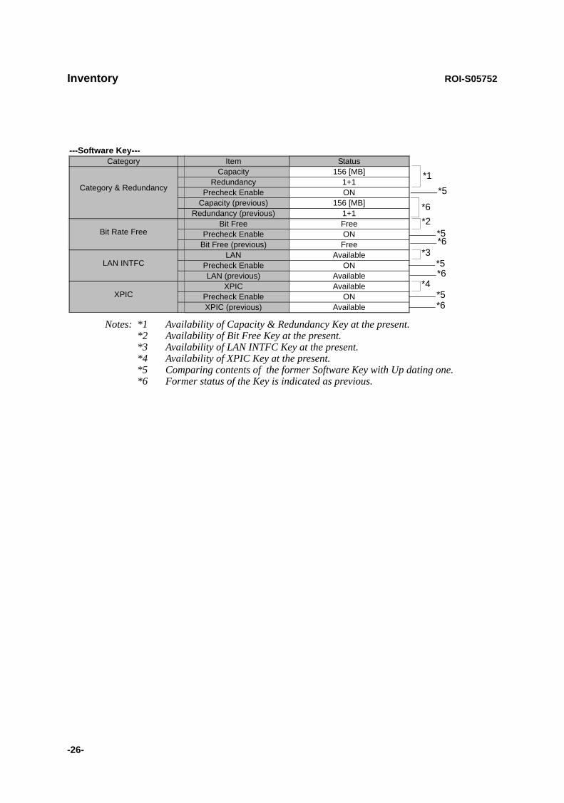
---Software Key---Category Item Status
Category & Redundancy
Capacity 156 [MB]Redundancy 1+1
Precheck Enable ONCapacity (previous) 156 [MB]
Redundancy (previous) 1+1
Bit Rate FreeBit Free Free
Precheck Enable ONBit Free (previous) Free
LAN INTFCLAN Available
Precheck Enable ONLAN (previous) Available
XPICXPIC Available
Precheck Enable ONXPIC (previous) Available
Notes: *1 Availability of Capacity & Redundancy Key at the present. *2 Availability of Bit Free Key at the present.*3 Availability of LAN INTFC Key at the present. *4 Availability of XPIC Key at the present.*5 Comparing contents of the former Software Key with Up dating one.*6 Former status of the Key is indicated as previous.
*3
*4
*1*5
*5
*5*6
*6
*6*2
*6
*5

ROI-S05752 AUX. I/O
-27-
3. AUX. I/O
Six input (photocoupler) and six output (relay) are provided in the IDU for external control and alarm outputs of Housekeeping and Cluster.
1 Click on the “AUX I/O” button in “LCT MENU”.
LCT MENU
Alarm/StatusEquipment SetupInventoryAUX I/OMaintenanceProvisioningMeteringPMON(History)
---INPUT---CONDITION
INPUT1 CloseINPUT2 CloseINPUT3 OpenINPUT4 OpenINPUT5 OpenINPUT6 Open
---OUTPUT---Value
OUTPUT1 OpenOUTPUT2 OpenOUTPUT3 OpenOUTPUT4 Open
OpenClose
2 Click menu button of required number of OUTPUT,
3 Select “Open” or “Close” to decide output mode to apply for event output,
4 Click on the “SET” button in a Common area to execute setup. Note: From INPUT 1 to INPUT 6 can be assigned to HK1 to
HK6 input.From INPUT 3 to INPUT 6 can be used to Cluster IN4 to Cluster IN1.From OUTPUT 1 to OUTPUT 4 can be assigned to HK OUT1 to HK OUT 4.From OUTPUT 1 to OUTPUT 4 can be used to Cluster OUT 1 to OUT 4.Cluster can be used up to 4 and for each Cluster IN# corresponding Cluster OUT# should be set in the opposite station.
5 Click on the “SET” button in Common area, then “OK” is displayed in Progress area when the setup is properly executed.
Note: “NG” and error message are displayed in Progress State area, if there is invalid setting in the Aux I/O.
Maintenance ROI-S05752
-28-
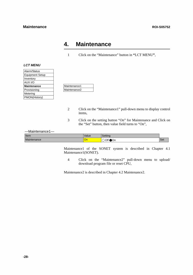
4. Maintenance1 Click on the “Maintenance” button in “LCT MENU”,
2 Click on the “Maintenance1” pull-down menu to display control items,
3 Click on the setting button “On” for Maintenance and Click on the “Set” button, then value field turns to “On”,
Maintenance1 of the SONET system is described in Chapter 4.1 Maintenance1(SONET).
4 Click on the “Maintenance2” pull-down menu to upload/download program file or reset CPU,
Maintenance2 is described in Chapter 4.2 Maintenance2.
LCT MENU
Alarm/StatusEquipment SetupInventoryAUX I/OMaintenanceProvisioningMeteringPMON(History)
Maintenance1Maintenance2
---Maintenance1---Item Value SettingMaintenance On Off On Set

ROI-S05752 Maintenance
-29-
4.1 Maintenance1(SONET)
---Maintenance1---Item Value SettingMaintenance On Off On SetTX SW Manual Control Auto Auto No.1 No.2 SetRX SW Manual Control Auto Auto No.1 No.2 SetRX SW Maintenance Mode ManualATPC Manual Control(No.1) On Off On [dB] SetATPC Manual Control(No.2) Off Off On SetTX Mute Control(No.1) Off Off On SetTX Mute Control(No.2) Off Off On SetCW Control(No.1) Off Off On SetCW Control(No.2) Off Off On SetAPS Manual Control Auto Auto Working Protection SetAPS Maintenance Mode ManualIF Loopback(No.1) Off Off On SetIF Loopback(No.2) Off Off On SetMain Loopback (Near End) Off Off On SetMain Loopback (Far End) Off Off On SetLAN Device Reset SetLinearizer Control(No.1) Auto Auto Forced Reset SetLinearizer Control(No.2) Auto Auto Forced Reset SetALS Restart --- 2sec 90sec SetXPIC Control Local(No.1) Auto Auto Forced Reset SetXPIC Control Local(No.2) Auto Auto Forced Reset SetXPIC Control Remote(No.1) Auto Auto Forced Reset SetXPIC Control Remote(No.2) Auto Auto Forced Reset Set
---Offline Maintenance---DADE Adjust --- DADE Offset DADE DADE Off SetRF SUB Band Select(No.1) --- A SetRF SUB Band Select(No.2) --- A SetAntenna Alignment Mode(No.1) Off Off On SetAntenna Alignment Mode(No.2) Off Off On Set

Maintenance ROI-S05752
-30-
TX SW Manual Control
1 Click on the setting button “On” of the “Maintenance” and click on the “Set” button, then value field of the Maintenance turns from “Off” to “On”.
In Maintenance “On” mode, external parallel alarm outputs excepts CPU and PS ALM are masked and automatic control is inhibited.
Control operation using LCT must be performed in Maintenance “On” condition.
2 Click on the setting button “Auto”, “No. 1” or “No. 2” TX SW to select TX SW control mode and Click on the “Set” button, then the value field of the corresponding SW manual control change to the selected mode.Auto: Normal operation modeNo. 1 or No. 2: Manual control mode
ATPC Manual Control
3 Click on the setting button “On” and enter attenuation value within ATPC range, then click on the “Set” button,
In the XPIC configuration, the ATPC/MTPC can not be set in the Sub Master station. The setup is applied from the Main Master station.
Note *1 Additional attenuator from 0 to 5 dB can be added.
---Maintenance1---Item Value SettingMaintenance On Off On SetTX SW Manual Control Auto Auto No.1 No.2 SetRX SW Manual Control Auto Auto No.1 No.2 Set
---Maintenance1---Item Value SettingMaintenance On Off On SetATPC Manual Control(No.1) On Off On [dB] SetATPC Manual Control(No.2) Off Off On Set
ATPC/MTPC Range (SONET)
ModulationMode
Frequency Band (GHz) 6 7-8 10-11 13 15 18 23 26 28 32 38
128QAM ATPC Range 0 to 20 dB 0 to 20 dB
MTPC Range 0 to 20 dB*1 0 to 20 dB

ROI-S05752 Maintenance
-31-
TX Mute Control
4 Click on the setting button “On” to select TX Mute Control,
5 Click on the “Set” button and the value field change to “On”,Caution: The control affects the radio link connection.
CW Control
6 Click on the setting button “On” to set CW Control ( ) and click on the “Set” button, then value field turns to “On”,Caution: The control affects the radio link connection.
Note: When set to CW Control “On”, unmodulated RF signal is emitted.
APS Manual Control
7 Click on the control button either “Working” or “Protection” of APS control and click on the “Set” button, then value field turns to selected value,
Normal setting mode is “Auto”, set to this mode after maintenance operation has been completed. Select “Working” to keep the Working INTFC (the INTFC card is installed in Slot (1)) to Online in Manual, Select “Protection” to keep the Protection INTFC (the INTFC card is installed in Slot (2)) to Online in Manual.
The Maintenance Mode of “Manual” or “Forced” is displayed underneath that is selected in “Provisioning”.
Note:The control applies only to APS configuration.
---Maintenance1---Item Value SettingMaintenance On Off On SetTX Mute Control(No.1) Off Off On SetTX Mute Control(No.2) Off Off On Set
---Maintenance1---Item Value SettingMaintenance On Off On SetCW Control(No.1) Off Off On SetCW Control(No.2) Off Off On Set

Maintenance ROI-S05752
-32-
IF Loopback
8 Click on the setting button “On” for the IF Loopback ( ) and click on the “Set” button, then value field turns to “On”,Caution: The control interrupts all traffic between 2 stations.
Note: The control applies to IF loopback in local MODEM.
Main Loopback
9 Click on the setting button “On” of the required OC-3 INTFC to be looped back and click on the “Set” button, then controlled value appears in value field,Caution: The control interrupts all traffic between 2 stations.Caution: Far End Loopback control will be canceled if radio
link failure occurs under the control has been executed.
For OC-3 (ELE)
For OC-3 (OPT) (APS)
---Maintenance1---Item Value SettingMaintenance On Off On SetAPS Manual Control Auto Auto Working Protection SetAPS Maintenance Mode Manual
---Maintenance1---Item Value SettingMaintenance On Off On SetIF Loopback(No.1) Off Off On SetIF Loopback(No.2) Off Off On Set
---Maintenance1---Item Value SettingMaintenance On Off On SetMain Loopback (Near End) Off Off On SetMain Loopback (Far End) Off Off On Set
---Maintenance1---Item Value SettingMaintenance On Off On SetMain Loopback (Near End) INTFC (1) Off Off On SetMain Loopback (Near End) INTFC (2) Off Off On SetMain Loopback (Far End) Off Off On Set
ROI-S05752 Maintenance
-33-
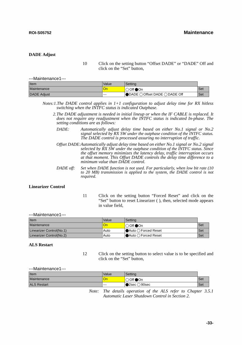
DADE Adjust
10 Click on the setting button “Offset DADE” or “DADE” Off and click on the “Set” button,
Notes:1.The DADE control applies in 1+1 configuration to adjust delay time for RX hitless switching when the INTFC status is indicated Outphase.
2.The DADE adjustment is needed in initial lineup or when the IF CABLE is replaced. It does not require any readjustment when the INTFC status is indicated In-phase. The setting conditions are as follows:DADE: Automatically adjust delay time based on either No.1 signal or No.2
signal selected by RX SW under the outphase condition of the INTFC status. The DADE control is processed assuring no interruption of traffic.
Offset DADE:Automatically adjust delay time based on either No.1 signal or No.2 signal selected by RX SW under the outphase condition of the INTFC status. Since the offset memory minimizes the latency delay, traffic interruption occurs at that moment. This Offset DADE controls the delay time difference to a minimum value than DADE control.
DADE off: Set when DADE function is not used. For particularly, when low bit rate (10 to 20 MB) transmission is applied to the system, the DADE control is not required.
Linearizer Control
11 Click on the setting button “Forced Reset” and click on the “Set” button to reset Linearizer ( ), then, selected mode appears in value field,
ALS Restart
12 Click on the setting button to select value is to be specified and click on the “Set” button,
Note: The details operation of the ALS refer to Chapter 3.5.1 Automatic Laser Shutdown Control in Section 2.
---Maintenance1---Item Value SettingMaintenance On Off On SetDADE Adjust --- DADE Offset DADE DADE Off Set
---Maintenance1---Item Value SettingMaintenance On Off On SetLinearizer Control(No.1) Auto Auto Forced Reset SetLinearizer Control(No.2) Auto Auto Forced Reset Set
---Maintenance1---Item Value SettingMaintenance On Off On SetALS Restart --- 2sec 90sec Set
Maintenance ROI-S05752
-34-
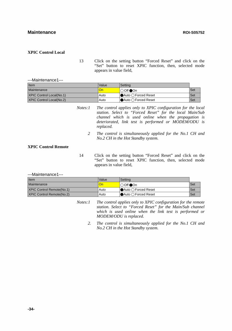
XPIC Control Local
13 Click on the setting button “Forced Reset” and click on the “Set” button to reset XPIC function, then, selected mode appears in value field,
Notes:1 The control applies only to XPIC configuration for the local station. Select to “Forced Reset” for the local Main/Sub channel which is used online when the propagation is deteriorated, link test is performed or MODEM/ODU is replaced.
2 The control is simultaneously applied for the No.1 CH and No.2 CH in the Hot Standby system.
XPIC Control Remote
14 Click on the setting button “Forced Reset” and click on the “Set” button to reset XPIC function, then, selected mode appears in value field,
Notes:1 The control applies only to XPIC configuration for the remote station. Select to “Forced Reset” for the Main/Sub channel which is used online when the link test is performed or MODEM/ODU is replaced.
2. The control is simultaneously applied for the No.1 CH and No.2 CH in the Hot Standby system.
---Maintenance1---Item Value SettingMaintenance On Off On SetXPIC Control Local(No.1) Auto Auto Forced Reset SetXPIC Control Local(No.2) Auto Auto Forced Reset Set
---Maintenance1---Item Value SettingMaintenance On Off On SetXPIC Control Remote(No.1) Auto Auto Forced Reset SetXPIC Control Remote(No.2) Auto Auto Forced Reset Set

ROI-S05752 Maintenance
-35-
RF SUB Band Select
15 Click on the menu button, select required Sub-Band from pull-down menu, and click on the “Set” button,
Note: This is an offline menu item to be carried out after a Sub-Band BPF change in the ODU. Refer to Appendix RF Frequency Plan in section 1 for details of Sub-Band versus Frequency Range.
Antenna Alignment Mode
16 Click on the setting button “On”, and click on the “Set” button, to apply Antenna Alignment Mode ( ), then, value field turns to “On”,
Notes: 1 The setting “On” is applied for antenna orientation or RX LEV reading when using NLITE E Monitor unit.
2 For the antenna orientation, set the TX power to the required level by ATPC Manual Control or MTPC mode at the opposite site.
3 The Antenna Alignment Mode is used for extending the dynamic range of the NLITE E Monitor unit. In order to measure in high range of AGC V, it is mandatory required to set Antenna Alignment Mode to ON. If not set to ON, the indicated AGC voltage is not guaranteed value.
4 No. 1 and No. 2 apply for 1+1 configuration.
---Maintenance1---Item Value SettingMaintenance On Off On SetRF SUB Band Select(No.1) --- A SetRF SUB Band Select(No.2) --- A Set
ABCDEFGHJ
---Maintenance1---Item Value SettingMaintenance On Off On SetAntenna Alignment Mode(No.1) Off Off On SetAntenna Alignment Mode(No.2) Off Off On Set
Maintenance ROI-S05752
-36-
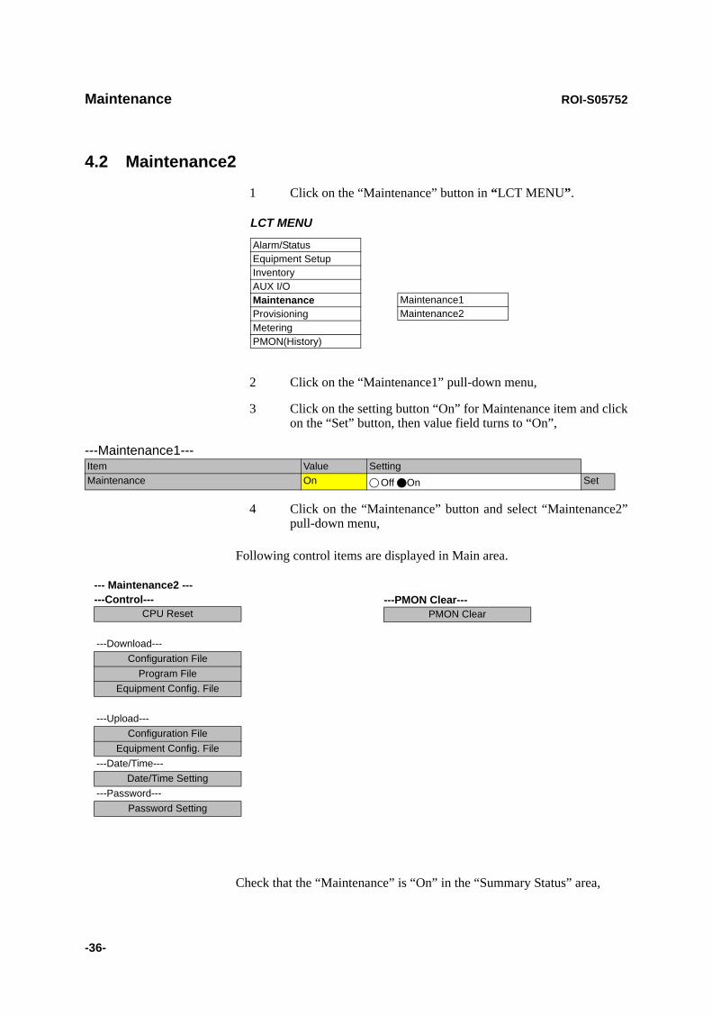
4.2 Maintenance2
1 Click on the “Maintenance” button in “LCT MENU”.
2 Click on the “Maintenance1” pull-down menu,
3 Click on the setting button “On” for Maintenance item and click on the “Set” button, then value field turns to “On”,
4 Click on the “Maintenance” button and select “Maintenance2” pull-down menu,
Following control items are displayed in Main area.
Check that the “Maintenance” is “On” in the “Summary Status” area,
LCT MENU
Alarm/StatusEquipment SetupInventoryAUX I/OMaintenanceProvisioningMeteringPMON(History)
Maintenance1Maintenance2
---Maintenance1---Item Value SettingMaintenance On Off On Set
--- Maintenance2 --- ---Control---
CPU Reset
---Download---Configuration File
Program FileEquipment Config. File
---Upload---Configuration File
Equipment Config. File---Date/Time---
Date/Time Setting---Password---
Password Setting
---PMON Clear---PMON Clear

ROI-S05752 Maintenance
-37-
CPU Reset
5 Click on the “CPU Reset” button,
6 Click on the control button “CTRL” for IDU or “ODU” and “No. 1 or No. 2” (in 1+1 ODU only), and click “Execute” button in CPU Reset dialog box,Caution: The control affects the radio link connection.
Check “with ROM (Program) Switching” check box when the program file for “CTRL” or “ODU” is newly down loaded and existing program file will be replaced with new one.
Note: When Click on the “Execute” button to reset CPU of the “CTRL”, then CTRL restarts, the LCT is disconnected.Access the LCT to the NLITE E NEO from the beginning.
7 Click on the “Close” button to dismiss the “CPU Reset” dialog box,
PMON Clear
8 Click on the “PMON Clear” button,
Perform this operation when beginning the service operation to delete all PMON and RMON data that were produced in installation,
9 Click on the “Execute” button,
10 Click on the “Close” button when “OK” is displayed in Progress area,

Maintenance ROI-S05752
-38-
Download Configuration File
11 Click on the “Configuration File” button “Download” menu,
12 Select the file Type “Net Work Config” or “Mib Config”,
13 Enter the location of the Configuration file in File field or click on the “Browser” button to display location in the hard disk or floppy disk,
14 Click on the “Execute” button to start down load, Caution: The control affects the radio link connection.Caution: While data is being transmitted, do not remove the
USB cable connecting the IDU with the PC.
15 After download has been completed, click on the “Update” button for the corresponding configuration will be operated with updated file,
16 Click on the “Close” button to dismiss the “Download Configuration” dialog box,

ROI-S05752 Maintenance
-39-
Download Program
17 Click on the “Program File” of “Download” menu,
18 Click on the “CTRL”, “ODU”, “FPGA” or “Package Program” and corresponding Sub-item control button,
19 Enter the location of the Program File in File field or click on the “Browser” to display location in the hard disk or floppy disk,
20 Click on the “Execute” button to start the download of program file, Caution: While data is being transmitted, do not remove the
USB cable connecting the IDU with the PC.
21 After download has been completed, click on the “CPU Reset.” button,Caution: The control affects the radio link connection.
22 Select on control button “CTRL” for IDU or “ODU” or “No. 1 or No. 2” (in 1+1 ODU only), and click “Execute” button in CPU Reset dialog box,
23 Click on the “Close” button to dismiss the “Download Configuration” dialog box,

Maintenance ROI-S05752
-40-
Download Equipment
24 Click on the “Equipment Config File” of “Download” menu,
25 Enter the location of the “Equipment Config File” in File field or click on the “Browser” button to display location in the hard disk, floppy disk or MMC, click on the “Execute” button to start the download,Caution: While data is being transmitted, do not remove the
USB cable connecting the IDU with the PC.
26 After download has been completed, click on the “Update” button for the CTRL will be operated with updated config file,Caution: The control affects the radio link connection.
27 Click on the “Close” button to dismiss the “Download Equipment” dialog box,
Upload Configuration File
28 Click on the “Configuration File” of “Upload” menu,
29 Select the file Type “Net Work Config” or “Mib Config”,
30 Enter the directory of the file name where the uploaded file will be saved,
31 Click on the “Execute” button to start the uploading, Caution: While data is being transmitted, do not remove the
USB cable connecting the IDU with the PC.

ROI-S05752 Maintenance
-41-
32 After Configuration File has been uploaded, click on the “Close” button to dismiss the “Upload Configuration” dialog box,
Upload Equipment Config File
33 Click on the “Equipment Config File” of “Upload” menu,
34 Enter the directory of the file name where the uploaded file will be saved,
35 Click on the “Execute” button to start the uploading, Caution: While data is being transmitted, do not remove the
USB cable connecting the IDU with the PC.
36 After Equipment Config File has been uploaded, click on the “Close” button to dismiss the “Upload Equipment” dialog box,

Maintenance ROI-S05752
-42-
Date/Time Setting
37 Click on the “Date/Time Setting” button of “Network” menu,
38 Click on the “Display PC Time” button, then the PC “Date”and“Time” are indicated in the fields,
39 Click on the “Execute” button, then, Date/Time setting for the CTRL is performed,
40 Click on the “Close” button to dismiss the “Date/Time Setting” dialog box,
Password Setting
41 Click on the “Password Setting” button,
42 Enter the current password in “Old Password” entry field,
43 Enter the new password in “New Password” entry field,
44 Enter the same password written in “New Password” entry field in “Confirm new password” entry field,
45 Click on the “OK” button after confirmed “New Password” and “Confirm new password”,
46 Click on the Maintenance1, set Maintenance “Off” and click on the “Set” button, then value field turns to “Off”.
ROI-S05752 Provisioning
-43-
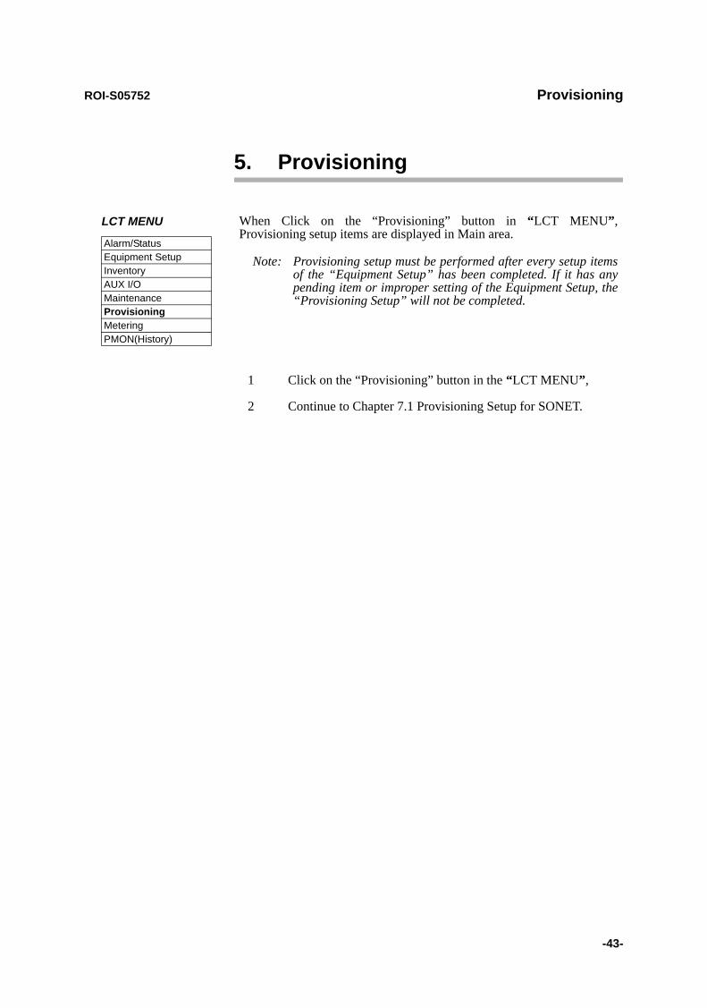
5. Provisioning
1 Click on the “Provisioning” button in the “LCT MENU”,
2 Continue to Chapter 7.1 Provisioning Setup for SONET.
LCT MENU
Alarm/StatusEquipment SetupInventoryAUX I/OMaintenanceProvisioningMeteringPMON(History)
When Click on the “Provisioning” button in “LCT MENU”, Provisioning setup items are displayed in Main area.
Note: Provisioning setup must be performed after every setup items of the “Equipment Setup” has been completed. If it has any pending item or improper setting of the Equipment Setup, the “Provisioning Setup” will not be completed.
Provisioning ROI-S05752
-44-
5.1 Provisioning Setup (SONET)
Note: To execute setup for each item, every time Click on the “SET” button in common area.
BER Threshold Setting
1 Click on the “BER Threshold Setting” sub-menu button in “Provisioning”,
2 Click on the control button of required BER threshold level for “High BER Threshold” and “LOW BER Threshold” of MODEM and E-BER (DMR)/E-BER (MUX) and SD (DMR)/SD (MUX) of INTFC.
---BER Threshold Setting---High BER Threshold 1E-3 1E-4 1E-5Low BER Threshold 1E-6 1E-7 1E-8 1E-9E-BER(DMR) 1E-3 1E-4 1E-5SD(DMR) 1E-6 1E-7 1E-8 1E-9E-BER(MUX) 1E-3 1E-4 1E-5SD(MUX) 1E-6 1E-7 1E-8 1E-9
ROI-S05752 Provisioning
-45-
SC Assignment
3 Click on the “SC Assignment” sub-menu button in “Provisioning”,
4 Click on the menu button of each RS-232C( ) and V-11-( ) and select item from pull down menu to assign a SC, SOH Byte or select Not used,
Notes: *1 assignable SC for RS-232C-1, -2.*2 assignable SC for V-11-1, -2.
---SC Assignment---RS-232C-1 SC1RS-232C-2 SC2V-11-1 SC3V-11-2 SC4V-11-1 Direction Setting Co-directional Contra-directionalV-11-2 Direction Setting Co-directional Contra-directional
Not Used Not Used SC1 SC1 SC2 SC2 SC3 SC3 SC4 SC4E1(MUX) E1(MUX)F1(MUX) F1(MUX)E1(DMR) DCCr(MUX)F1(DMR) E1(DMR)*1 F1(DMR)
DCCr(DMR)*2

Provisioning ROI-S05752
-46-
LAN Port Setting
5 Click on the “LAN Port Setting” sub-menu button in “Provisioning”,
6 Click on the setting button for each item,Notes: 1. LAN Port Setting - Switching function (only for INTFC (SUB)):
This is a setup if the Switch Hub is used between Port1 and Port2 or it does not used when the signal domain of the radio link shares with the Port1 and Port2. (It can be used only Shared Mode, or not be used in the Separated Mode of the Port1 and Port2.)Disabled: No use of Ports for the Switch Hub. (default value)Enabled: Use of Ports for the Switch Hub.
2. Clock Source Setting (only for INTFC (MAIN) default value: Internal Clock)This is a setup of Clock Source applied for framing into radio signal. Generally, a clock is used independently for respective sending/receiving using Internal Clock. Set to DMR=>Internal Clock when it makes synchronizing to the DMR. In this case, set to Internal Clock at the opposite site to avoid Timing Loop, because if it is set to DMR at the local and the opposite site, Timing Loop is caused by the setting. In the DMR=>Internal Clock mode, the clock is synchronized to received signal when the radio link is normal state but it is switched to the Internal Clock if the radio link is interrupted.
3. Port Usage: Use of LAN Port or no use. (default value is Not Used for MAIN, Used for SUB)
4. Speed&Duplex:Setting for Port speed and Duplex. Referring to the following table, set the Port mode according to the associated equipment which it is to be connected. Note that if the setting mode differs from associated equipment, it may be caused performance degradation or link loss. (default value is AUTONEG(Auto MDI/MDIX))
5. Flow Control:On: Effective flow control (default value is On) Off: Non-effective flow control.
6. Collision Report:In HALF-Duplex mode, it is selected that is reported or not reported about Collision conditions at each port. (default value is Not Report)
7. Link Loss Forwarding:Setting of the Link Loss Forwarding mode is effective or no effective. (See Link Loss Forwarding description in the Section II Operation) (default value is Disabled)

ROI-S05752 Provisioning
-47-
√ : A setup is possible.
* MDI/MDI-X is selected according to the cable type or terminal type to be used (straight or cross type).
(For LAN/WS INTFC in SUB)
EXTERNAL EQUIPMENT
SETTING POSITION
Aut
o N
egot
iatio
n
10B
ASE
-T/H
alf D
uple
x
10B
ASE
-T/F
ull D
uple
x
100B
ASE
-TX/
Hal
f Dup
lex
100B
ASE
-TX/
Full
Dup
lex
10B
ASE
-T/H
alf (
FIX)
100B
ASE
-TX/
Hal
f (FI
X)
IDU PORTSETTING POSITION
Auto Negotiation (Auto MDI/MDI-X) √ ⎯ ⎯ ⎯ ⎯ √ √
10BASE-T/Half Duplex (MDI/MDI-X*) ⎯ √ ⎯ ⎯ ⎯ ⎯ ⎯
10BASE-T/Full Duplex (MDI/MDI-X*) ⎯ ⎯ √ ⎯ ⎯ ⎯ ⎯
100BASE-TX/Half Duplex (MDI/MDI-X*) ⎯ ⎯ ⎯ √ ⎯ ⎯ ⎯
100BASE-TX/Full Duplex (MDI/MDI-X*) ⎯ ⎯ ⎯ ⎯ √ ⎯ ⎯
---INTFC (SUB) Setting---Switching Function Disabled Enabled
---Port1---Port Usage Not Used UsedSpeed & Duplex AUTONEG (Auto-MDI/MDIX)Flow Control Off On Collision Report Not Report ReportLink Loss Forwarding Disabled Enabled
---Port2---Port Usage Not Used UsedSpeed & Duplex AUTONEG (Auto-MDI/MDIX)Flow Control Off On Collision Report Not Report ReportLink Loss Forwarding Disabled Enabled
Provisioning ROI-S05752
-48-
(For LAN/WS INTFC in MAIN)
(For GbE INTFC)
Notes: 1. Media Type:Selects interface connector type:
SEP: Optical Interface for 1000BASE-SX (default value)RJ-45: Electrical Interface for 1000BASE-T
2. Speed&Duplex:Setting for Port speed and Duplex: AUTONEG(1000MB Full Duplex) (fixed)
4. Flow Control: On: Effective flow control (default value is On) Off: Non-effective flow control.
5. Link Loss Forwarding:
Setting of the Link Loss Forwarding mode is effective or no effective. (See Link Loss Forwarding description in the Section II Operation) (default value is Disabled)
---INTFC (MAIN) Setting---Switching Function Disabled EnabledClock Source Setting Internal Clock DMR=>Internal Clock
---Port1---Port Usage Not Used UsedSpeed & Duplex AUTONEG (Auto-MDI/MDIX)Flow Control Off On Collision Report Not Report ReportLink Loss Forwarding Disabled Enabled
---Port2---Port Usage Not Used UsedSpeed & Duplex AUTONEG (Auto-MDI/MDIX)Flow Control Off On Collision Report Not Report ReportLink Loss Forwarding Disabled Enabled
---LAN Port Setting---Switching Function Disabled Enabled
---Port---Media Type SFP RJ-45Speed & Duplex AUTONEG (1000MB Full Duplex)Flow Control Off On Link Loss Forwarding Disabled Enabled

ROI-S05752 Provisioning
-49-
OC-3 Setting
7 Click on the “OC-3 Setting” sub-menu button in “Provisioning”,
8 Click on the either “Disabled” or “Enabled” control button,
Note: Refer to Chapter “3.5.6 MS-AIS Generation” in Section 2 for the details.
9 Click on the “Disabled” control button of the ALS,
Note: ALS “Enabled” applies only for OC-3 Optical Interface.
10 Click on the “Enabled” and required ALS interval control button when the ALS is configured in the system,
Note: Refer to Chapter “3.5.1 Automatic Laser Shutdown Control” in Section 2 for the details.
TX Power Control
11 Click on the “TX Power Control” sub-menu button in “Provisioning”,
12 Enter required values in each control entry field within specified range,
(1) ATPC mode in 1+0 or Hot Standby configuration
---MS-AIS Generation---MS-AIS Generation Disabled Enabled
---ALS------ALS---ALS Function Disabled EnabledALS Interval 60sec 180sec 300sec
---TX Power Control--- RangeATPC Threshold Level [dBm] -60.0 -73.0 to -30.0Additional ATT[dB] 0 0 to 5ATPC Range(MAX)[dB] 0 -24 to -0ATPC Range(MIN)[dB] -24ATPC Power Mode Hold MAX MIN

Provisioning ROI-S05752
-50-
(2) ATPC mode in Twinpath configuration
(3) MTPC mode in Twinpath configuration
Notes: 1 No.1 and No.2 are indicated in Twinpath configuration only.2 For Hot Standby configuration, the TX Power Control effects
both No. 1 and No. 2 ODUs.3 ATPC/MTPC Range varies depending on RF frequency band
and modulation scheme.4 ATPC Threshold level Range varies depending on modulation
scheme and RF signal channel separation.5 ATPC power Mode selects the ATPC activation when ATPC
function has been failed:Hold: Maintain the current TX output level at the time of
the ATPC is malfunction.MAX: Maintain the ATPC maximum TX output level at
the time of the ATPC is malfunction.MIN: Maintain the ATPC minimum TX output level at the
time of the ATPC is malfunction.6 In the XPIC configuration, this setup is performed at the Main
Master station, the ATPC/MTPC can not be set in the Sub Master station. The setup is applied from the Main Master station to the Sub Master station.
---TX Power Control--- RangeATPC Threshold Level(No.1) [dBm] -60.0 -73.0 to -30.0ATPC Threshold Level(No.2) [dBm] -60.0 -73.0 to -30.0Additional ATT(No.1) [dB] 0 0 to 5Additional ATT(No.2) [dB] 0 0 to 5ATPC Range(MAX)(No.1) [dB] 0 -20 to -0ATPC Range(MIN)(No.1) [dB] -20ATPC Range(MAX)(No.2) [dB] 0 -20 to -0ATPC Range(MIN)(No.2) [dB] -20ATPC Power Mode Hold MAX MIN
---TX Power Control--- RangeMTPC TX Power(No.1) [dB] -20 -20 to 0MTPC TX Power(No.2) [dB] -20 -20 to 0ATPC Threshold Level(No.1) [dBm] -60 -73 to -30ATPC Threshold Level(No.2) [dBm] -60 -73 to -30Additional ATT(No.1) [dB] 0 0 to 5Additional ATT(No.2) [dB] 0 0 to 5

ROI-S05752 Provisioning
-51-
Condition for TX/RX SW (only for 1+1 configuration)
13 Click on the “Condition for TX/RX SW” sub-menu button in “Provisioning”,
14 Click on the control button of required control mode for the TX SW and the RX SW,
Notes: 1 TX SW control mode is applied only for Hot Standby configuration.
2 For TX and RX SW Priority, select Non Priority for Non-revertive operation at TX or RX alarm condition is restored.
3 Manual mode of RX SW Maintenance Mode, disables the RX SW operation under either No. 1 or No. 2 RX route is alarmed.
4 Forced mode of RX SW Maintenance Mode, enables the RX SW operation through either or both No. 1 or No. 2 RX route is alarmed.
5 Early Warning provides less than 1E-9.
Condition for APS
15 Click on the control button of required setting mode for the APS,
Note: For the details of Condition for APS setting, see the Automatic Protection Switching (APS) in the Section II Operation.
----Condition for TX/RX SW---TX SW Priority Non Priority Priority No.1RX SW Priority Non Priority Priority No.1RX SW Maintenance Mode Manual ForcedRX SW Condition-Early Warning Included EW Excluded EW
----Condition for APS---APS Maintenance Mode Manual ForcedAPS Condition-SF(PROT) Priority High Priority LowAPS Condition-SD(B1) Included SD Excluded SDLock in Usage Not Used UsedLock in Count (times) 4 1 to 255Lock in Detect Time(min) 10 1 to 60Lock in Hold Time(min) 24 1 to 48
Provisioning ROI-S05752
-52-
Relay Setting
16 Click on the “Relay Setting” sub-menu button in “Provisioning”,
17 Click on the setting box crossed corresponding item and RL,Note: Display or non-display of Relay Setting items depends on Redundancy Setting.
Example: When setting to (1+0) mode, the items of No.2 side become non-display. At this moment, contact information ("Out") set so far are all cleared regarding the items which become non-display due to the setting change. Accordingly, users are required to set the setting information again when these items are redisplayed after setting change.
Note: From RL3 to RL6 can be assigned to CLUSTER1 to 4 OUTPUT but the same number of CLUSTER1 to 4 INPUT can not be assigned which number has been assigned to CLUSTER OUTPUT, or the CLUSTER can be assigned only for following condition.
Cluster can be used: IN + OUT ≤ 4
Note: When the selected item for RL assignment is invalid, “NG” and error message are displayed in Progress State area.
Cluster1 Input Disabled EnabledCluster2 Input Disabled EnabledCluster3 Input Disabled EnabledCluster4 Input Disabled Enabled

ROI-S05752 Provisioning
-53-
The following are assignable items for external alarm output in SONET system.
HK OUT1 HK OUT2 HK OUT3 HK OUT4 MAINTIDU CPU ALM PS ALM1 PS ALM2 ODU ALM1 ODU ALM2 ODU CPU/CABLE OPEN ALM1 ODU CPU/CABLE OPEN ALM2 LO REF1 LO REF2 ODU CPU ALM2 TX PWR ALM1 TX PWR ALM2 TX INPUT ALM1 TX INPUT ALM2 APC ALM1 APC ALM2 RX LEVEL ALM1 RX LEVEL ALM2 IDU ALM MOD ALM1 MOD ALM2 DEM ALM1 DEM ALM2 HIGH BER ALM1 HIGH BER ALM2 LOW BER ALM1 LOW BER ALM2 IF CABLE SHORT ALM1 IF CABLE SHORT ALM2 XIF ALM1XIF ALM2XREF ALM1XREF ALM2LOF1 LOF2 STM-1R LOS1-2 STM-1S LOS1-2OC-3 TF ALM1-2 CLUSTER ALM OUT1 CLUSTER ALM OUT2 CLUSTER ALM OUT3 CLUSTER ALM OUT4

Provisioning ROI-S05752
-54-
TCN Threshold (15min 1day)
18 Click on the “TCN Threshold (15min)” or “TCN Threshold (1day)” sub-menu button in “Provisioning”,
19 Enter required values in threshold OCR (Alarm Occur) and RCVR (Alarm Recover) fields of performance item,
Note: Do not mistake the setting such as the OCR ≤ RCVR or RCVR=0
.
PMON Select
20 Click on the “PMON Select” sub-menu button in “Provisioning”,
21 Enter required “RX level TCN Thresholdt” level in text field,
22 Click on the control button of “SES Activation Condition”,
----TCN Threshold (15min)---DMR MUXOCR RCVR OCR RCVR RANGE
OFS 900 90 900 90 0 to 900UAS 900 90 900 90 0 to 900ES 900 90 900 90 0 to 900SES 900 90 900 90 0 to 900BBE 1410 150 1410 150 0 to 2159100SEP 900 90 900 90 0 to 900
----TCN Threshold (1day)---DMR MUXOCR RCVR OCR RCVR RANGE
OFS 65534 650 65534 650 0 to 86400UAS 65534 650 65534 650 0 to 86400ES 65534 650 65534 650 0 to 86400SES 65534 650 65534 650 0 to 86400BBE 135360 13540 13560 13540 0 to 207273600SEP 65534 650 65534 650 0 to 86400
---PMON Select---RX Level TCN Threshold [dBm] −82.0SES Activation Condition 30[%] 15[%]

ROI-S05752 Provisioning
-55-
Others
23 Click on the “Others” sub-menu button in “Provisioning”,
XPIC Condition-Local Fail
24 Click on the either “REF LO->Self LO” or “Mute” control button,This setup defines the ODU operation when the reference LO signal from the IDU is lost.
Note: Select “REF LO → Self LO” when both V/H channels are used in degraded quality condition. Local signal is generated by the self LO OSC in the ODU. Then, the local signal is not synchronized with the opposite polarization and the XPIC function is irregularly operated.Select “Mute” when only normal channel is used in normal quality condition. The TX output signal of the failure ODU is shut off by the mute control. The XPIC function is not operated absolutely in this mode.
EOW2 External Setting
25 Click on the either “Normal” or “Invert” control button,
Note: Select “Invert” or “Normal” to set appropriate calling system for the associated system as follows. Set “Normal” when the NEO IDU is connected to NLITE E IDU/NEO IDU. Set “Invert” when the NEO IDU is connected to NLITE E+ IDU or Mx IDU.
Alarm Correlation Capability
26 Click on the either “On” or “Off” control button,
Note: Select “On” when really caused alarm is displayed. Select “Off” when including derived alarm is displayed.
27 Click on the “SET” button in Common area to define the setup.
---XPIC Condition- Local Fail---XPIC Condition - Local Fail REF LO->Self LO Mute
---EOW2 External Setting---EOW2 External Setting Normal Invert
---Alarm Correlation Capability---Alarm Correlation Capability Off On

Metering ROI-S05752
-56-
6. Metering1 Click on the “Metering” in “LCT MENU”,
2 Check the values indicated in metering text fields for each metering item,
Notes: 1. No.1 and No.2 are indicated only for 1+1 configuration.2. Both TX Power values of No.1 and No.2 are indicated in
Twinpath configuration only.3. TX Power value * is indicated for standby ODU in Hot
Standby configuration.4. Power Supply voltage of the ODU DC input varies
depending on IF cable length.5. During total number of erroneous bits and total number
of correctly received bits are calculating, “Calculating”is displayed.
6. In the 2-WAY mode, the values are displayed for each DIR-A and DIR-B.
LCT MENU
Alarm/StatusEquipment SetupInventoryAUX I/OMaintenanceProvisioningMeteringPMON(History)
----Metering---No.1 No.2
TX Power[dBm] +0.7 *RX Level[dBm] -65.2 -70.0Power Supply[V] -45 -45BER *.*E-10 Calculating

ROI-S05752 Metering
-57-
RMON(DMR)(1day)
3 Click on the “RMON(DMR)(7days/day)” sub-menu button in “PMON (History)”,
---RMON(DMR)(1day)--- Maintenance Mode: on
Port1
Date Time Status 1 2 3 4 5 61:2:3:4:5:6:7:8:9:10:11:12:13:14:15:16:17:18:
RX UNICASTRX BROADCASTRX MULTICASTRX PAUSERX CEC ERRRX FRAGMENTSRX 64RX 65-127RX 128-255RX 256-511RX 512-1023RX 1024-1536RX 1537-MAXRX JABBERSTX UNICASTTX BROADCASTTX MULTICASTTX PAUSE

Metering ROI-S05752
-58-
6.1 PMON (SONET)
6.1.1 PMON (History)
1 Click on the “PMON (History)” in “LCT MENU”,
2 Click on the “RELOAD” button in Common area,
RX Level(24H/15min)
3 Click on the “RX LEVEL(24H/15min)” sub-menu button in “PMON (History)”,
LCT MENU
Alarm/StatusEquipment SetupInventoryAUX I/OMaintenanceProvisioningMeteringPMON(History)
RX Level(24H/15min)RX Level(7days/day)DMR(W)(7days/day)DMR(W)(24H/15min)MUX(W)(7days/day)MUX(W)(24H/15min)
---RX Level (15min)--- Maintenance Mode: on : Current Time
Date Time Status MIN(No.1) MAX(No.1) MIN(No.2) MAX(No.2)2006/01/05 15:30-15:45 -59.7 -58.6 -59.3 -58.12006/01/05 15:45-16:00 -59.8 -58.7 -58.7 -58.22006/01/05 16:00-16:15 -59.5 -59.0 -58.7 -58.22006/01/05 16:15-16:30 -59.5 -59.0 -58.7 -58.22006/01/05 16:30-16:45 -59.5 -59.0 -71.2 -58.22006/01/05 16:45-17:00 -74.2 -55.8 -58.8 -54.12006/01/05 17:00-17:15 -59.5 -57.9 -58.8 -58.1

ROI-S05752 Metering
-59-
RX Level(7days/day)
4 Click on the “RX LEVEL(7days/day)” sub-menu button in “PMON (History)”,
DMR(W)(24H/15min)
5 Click on the “DMR(W)(24H/15min)” sub-menu button in “PMON (History)”,
DMR(W)(day)
6 Click on the “DMR(W)(7days/day)” sub-menu button in “PMON (History)”,
---RX Level (day)--- Maintenance Mode: on
Date Status MIN(No.1) MAX(No.1) MIN(No.2) MAX(No.2)2006/01/01 -59.7 -58.6 -59.3 -58.12006/01/02 -59.8 -58.7 -58.7 -58.22006/01/03 -59.5 -59.0 -58.7 -58.22006/01/04 -59.5 -59.0 -58.7 -58.22006/01/05 -59.5 -59.0 -71.2 -58.22006/01/06 -74.2 -55.8 -58.8 -54.12006/01/07 -59.5 -57.9 -58.8 -58.1
---DMR(W)(15min)---- Maintenance Mode: on : Current Time
Date Time Status OFS SEP BBE ES SES UAS2006/01/05 15:30-15:45 0 0 0 0 0 02006/01/05 15:45-16:00 0 0 0 0 0 02006/01/05 16:00-16:15 0 0 0 0 0 02006/01/05 16:15-16:30 0 0 0 0 0 02006/01/05 16:30-16:45 0 0 0 0 0 02006/01/05 16:45-17:00 0 0 0 0 0 02006/01/05 17:00-17:15 0 0 0 0 0 0
---DMR(W)(1day)--- Maintenance Mode: on
Date Status OFS SEP BBE ES SES UAS2006/01/01 0 0 0 0 0 02006/01/02 0 0 0 0 0 02006/01/03 0 0 0 0 0 02006/01/04 0 0 0 0 0 02006/01/05 0 0 0 0 0 02006/01/06 0 0 0 0 0 02006/01/07 0 0 0 0 0 0

Metering ROI-S05752
-60-
MUX(W)(24H/15min)
7 Click on the “MUX(W)(24H/15min)” sub-menu button in “PMON (History)”,
MUX(W)(7days/day)
8 Click on the “MUX(W)(7days/day)” sub-menu button in “PMON (History)”,
---MUX(W)(15min)---- Maintenance Mode: on : Current Time
Date Time Status OFS SEP BBE ES SES UAS2006/01/05 15:30-15:45 0 0 0 0 0 02006/01/05 15:45-16:00 0 0 0 0 0 02006/01/05 16:00-16:15 0 0 0 0 0 02006/01/05 16:15-16:30 0 0 0 0 0 02006/01/05 16:30-16:45 0 0 0 0 0 02006/01/05 16:45-17:00 0 0 0 0 0 02006/01/05 17:00-17:15 0 0 0 0 0 0
---MUX(W)(day)--- Maintenance Mode: on
Date Status OFS SEP BBE ES SES UAS2006/01/01 0 0 0 0 0 02006/01/02 0 0 0 0 0 02006/01/03 0 0 0 0 0 02006/01/04 0 0 0 0 0 02006/01/05 0 0 0 0 0 02006/01/06 0 0 0 0 0 02006/01/07 0 0 0 0 0 0
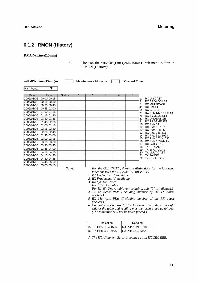
ROI-S05752 Metering
-61-
6.1.2 RMON (History)
RMON(Line)(15min)
9 Click on the “RMON(Line)(24H/15min)” sub-menu button in “PMON (History)”,
Notes: For the GbE INTFC, there are distinctions for the following functions from the 10BASE-T/100BASE-Tx
1. RX Undersize: Unavailable.2. RX Fragments: Unavailable.3. RX Symbol Errors:
For SFP: Available For RJ-45: Unavailable (un-counting, only "0" is indicated.)
4. TX Multicast PKts (Including number of the TX pause packets.)
5. RX Multicast PKts (Including number of the RX pause packets.)
6. Countable packet size for the following items shown in right side of the table and reading must be taken place as follows. (The indication will not be taken placed.)
7. The RX Alignment Error is counted as an RX CRC ERR.
---RMON(Line)(15min)--- Maintenance Mode: on : Current Time
Main Port1
Date Time Status 1 2 3 4 52006/01/05 00:00-00:15 1:
2:3:4:5:6:7:8:9:10:11:12:13:14:15:16:17:18:19:20:21:22:
RX UNICASTRX BROADCASTRX MULTICASTRX PAUSERX CEC ERRRX ALIGNMENT ERRRX SYMBOL ERRRX UNDERSIZERX FRAGMENTSRX Pkts 64RX Pkts 65-127RX Pkts 128-255RX Pkts 256-511RX Pkts 512-1023RX Pkts 1024-1536RX Pkts 1537-MAXRX JABBERSTX UNICASTTX BROADCASTTX MULTICASTTX PAUSETX COLLISION
2006/01/05 00:15-00:302006/01/05 00:30-00:452006/01/05 00:45-01:002006/01/05 01:00-01:152006/01/05 01:15-01:302006/01/05 01:30-01:452006/01/05 01:45-02:002006/01/05 02:00-02:152006/01/05 02:15-02:302006/01/05 02:30-02:452006/01/05 02:45-03:002006/01/05 03:00-03:152006/01/05 03:15-03:302006/01/05 03:30-03:452006/01/05 03:45-04:002006/01/05 04:00-04:152006/01/05 04:15-04:302006/01/05 04:30-04:452006/01/05 04:45-05:002006/01/05 05:00-05:15
Indication Reading15 RX Pkts 1024-1536 RX Pkts 1024-151816 RX Pkts 1537-MAX RX Pkts 1519-MAX
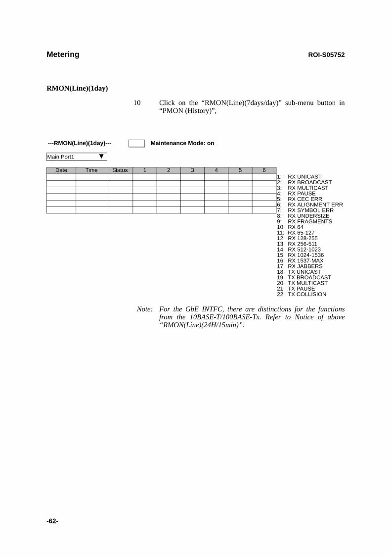
Metering ROI-S05752
-62-
RMON(Line)(1day)
10 Click on the “RMON(Line)(7days/day)” sub-menu button in “PMON (History)”,
Note: For the GbE INTFC, there are distinctions for the functions from the 10BASE-T/100BASE-Tx. Refer to Notice of above “RMON(Line)(24H/15min)”.
---RMON(Line)(1day)--- Maintenance Mode: on
Main Port1
Date Time Status 1 2 3 4 5 61:2:3:4:5:6:7:8:9:10:11:12:13:14:15:16:17:18:19:20:21:22:
RX UNICASTRX BROADCASTRX MULTICASTRX PAUSERX CEC ERRRX ALIGNMENT ERRRX SYMBOL ERRRX UNDERSIZERX FRAGMENTSRX 64RX 65-127RX 128-255RX 256-511RX 512-1023RX 1024-1536RX 1537-MAXRX JABBERSTX UNICASTTX BROADCASTTX MULTICASTTX PAUSETX COLLISION

ROI-S05752 Installation of USB
-63-
7. Installation of USB
Following procedure explains how to install the USB modem driver to a windows XP PC.
1. Connect the PC with a USB cable between the LCT port and the USB port,
2. Select “Install from a list or specific location [Advanced]” and Click on the “Next” button,
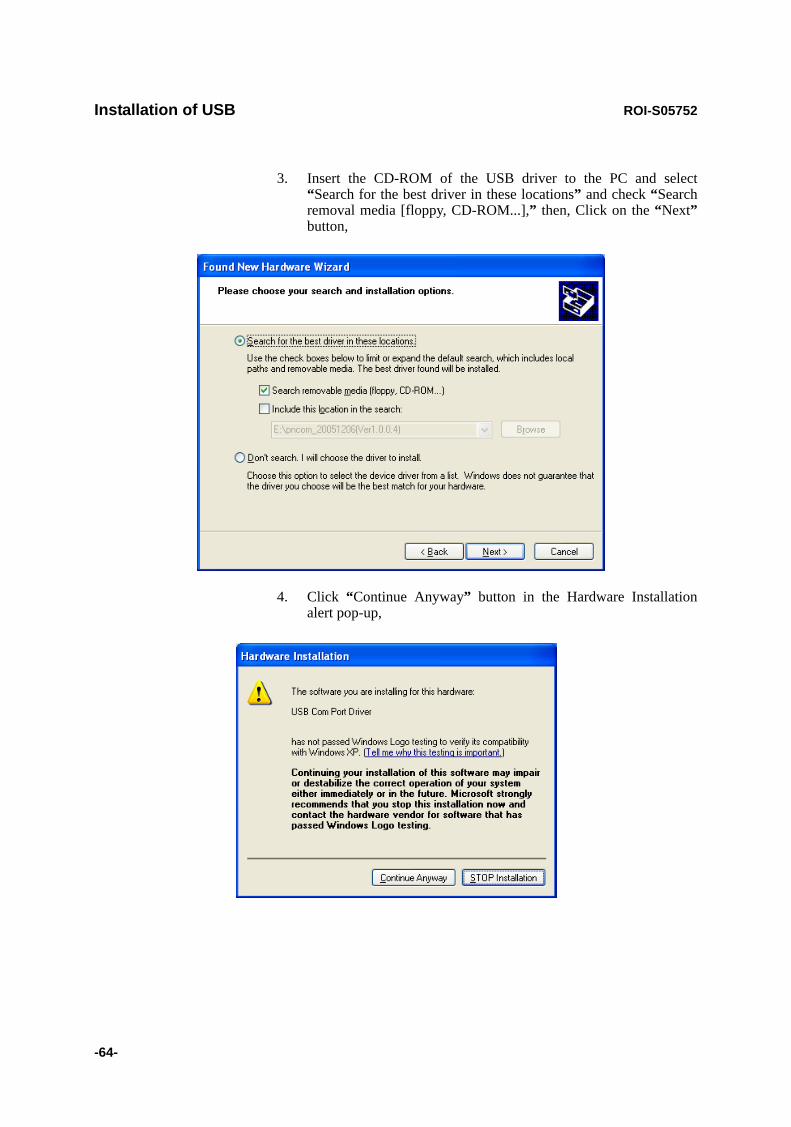
Installation of USB ROI-S05752
-64-
3. Insert the CD-ROM of the USB driver to the PC and select “Search for the best driver in these locations” and check “Search removal media [floppy, CD-ROM...],” then, Click on the “Next”button,
4. Click “Continue Anyway” button in the Hardware Installation alert pop-up,

ROI-S05752 Installation of USB
-65-
5. USB driver installation will be started,
6. Click “Finish” button in the “Found New Hardware Wizard” after installation has been completed.
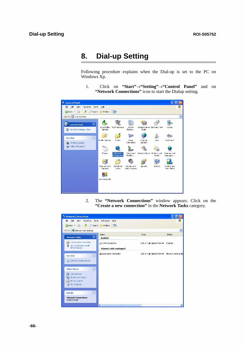
Dial-up Setting ROI-S05752
-66-
8. Dial-up Setting
Following procedure explains when the Dial-up is set to the PC on Windows Xp.
1. Click on “Start”→“Setting”→“Control Panel” and on “Network Connections” icon to start the Dialup setting.
2. The “Network Connections” window appears. Click on the “Create a new connection” in the Network Tasks category.
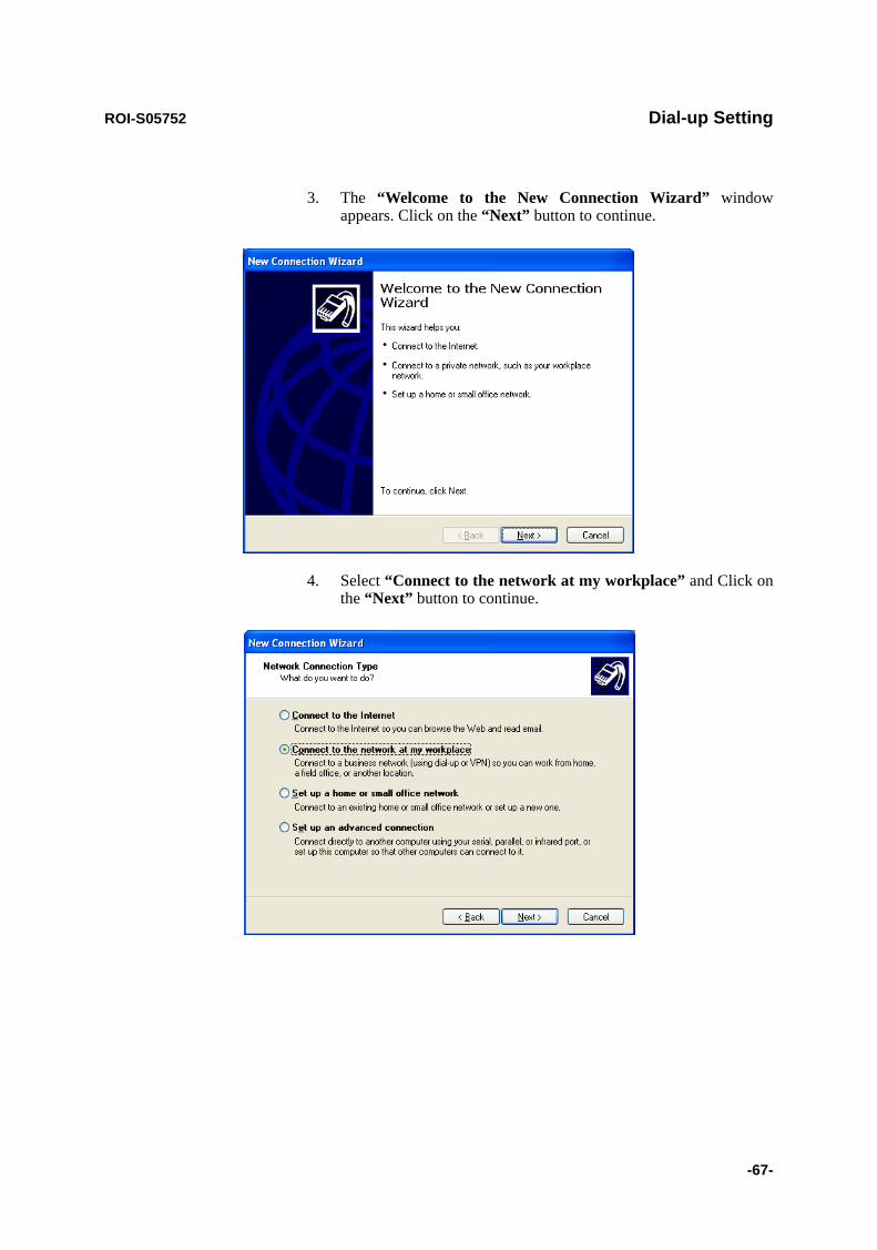
ROI-S05752 Dial-up Setting
-67-
3. The “Welcome to the New Connection Wizard” window appears. Click on the “Next” button to continue.
4. Select “Connect to the network at my workplace” and Click on the “Next” button to continue.

Dial-up Setting ROI-S05752
-68-
5. Select option “Dial-up connection” and Click on the “Next”button to continue.
6. On the “New Connection Wizard” window, enter “LCT” in the “Company Name” entry field and Click on the “Next” button to continue.
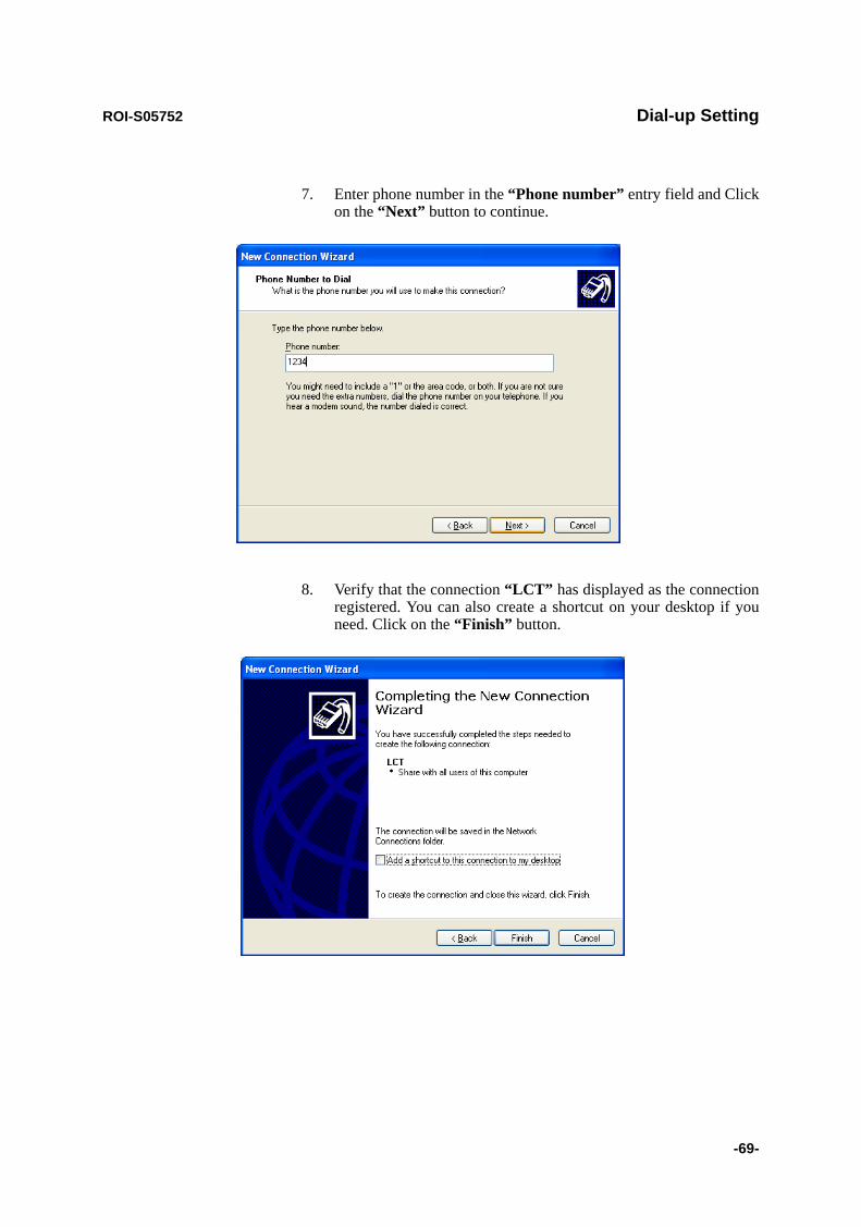
ROI-S05752 Dial-up Setting
-69-
7. Enter phone number in the “Phone number” entry field and Click on the “Next” button to continue.
8. Verify that the connection “LCT” has displayed as the connection registered. You can also create a shortcut on your desktop if you need. Click on the “Finish” button.

Dial-up Setting ROI-S05752
-70-
9. On “Connect LCT” dialog, click “Properties”,
10. Verify that “Modem-USB Modem Driver [COM(#)]” is displayed on the General dialog box connect using check box, and select “Show icon in notification area when connected” in the LCT Properties dialog. Then, Click on the “Configure” button.
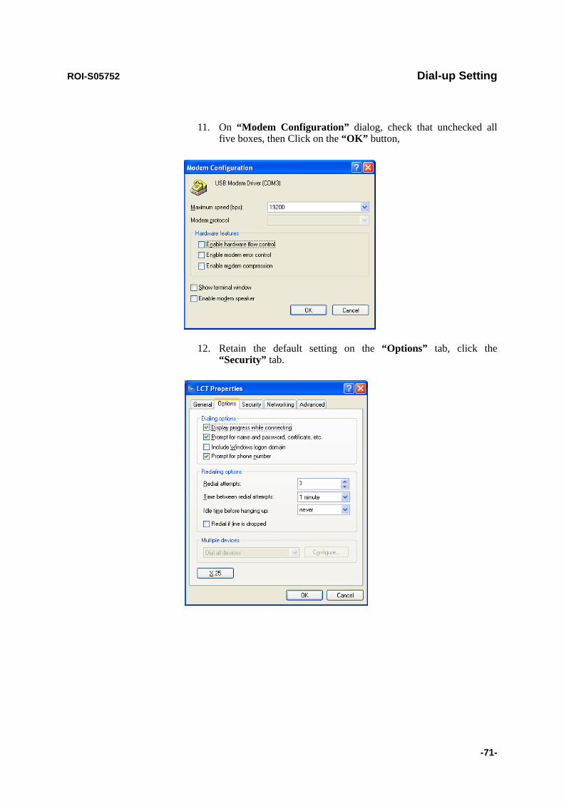
ROI-S05752 Dial-up Setting
-71-
11. On “Modem Configuration” dialog, check that unchecked all five boxes, then Click on the “OK” button,
12. Retain the default setting on the “Options” tab, click the “Security” tab.
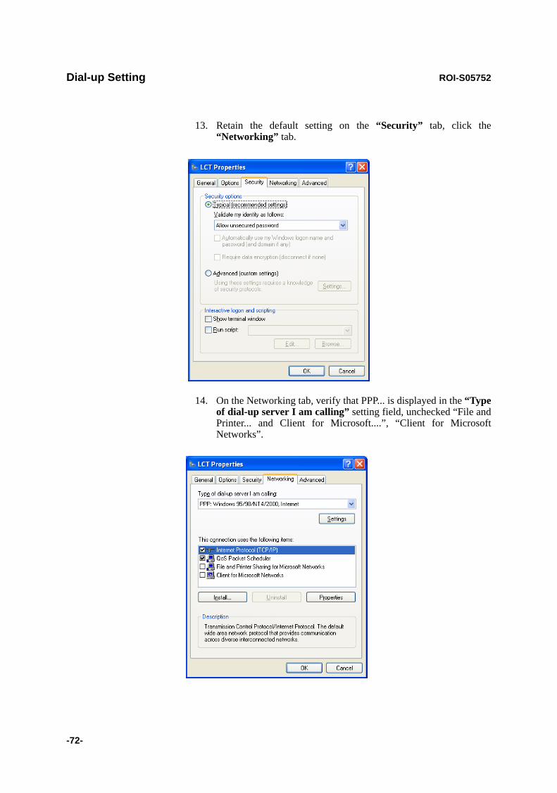
Dial-up Setting ROI-S05752
-72-
13. Retain the default setting on the “Security” tab, click the “Networking” tab.
14. On the Networking tab, verify that PPP... is displayed in the “Type of dial-up server I am calling” setting field, unchecked “File and Printer... and Client for Microsoft....”, “Client for Microsoft Networks”.
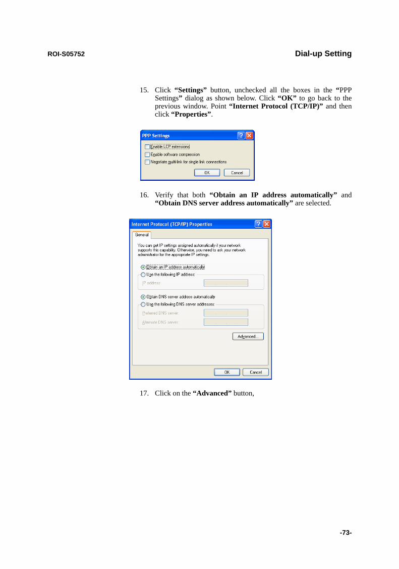
ROI-S05752 Dial-up Setting
-73-
15. Click “Settings” button, unchecked all the boxes in the “PPP Settings” dialog as shown below. Click “OK” to go back to the previous window. Point “Internet Protocol (TCP/IP)” and then click “Properties”.
16. Verify that both “Obtain an IP address automatically” and “Obtain DNS server address automatically” are selected.
17. Click on the “Advanced” button,

Dial-up Setting ROI-S05752
-74-
18. In the “Advanced TCP/IP Settings” dialog, mark check box of “Use default gateway on remote network” and for the PPP link is unchecked, then Click “OK”.
19. Retain the default setting on the “Advanced” tab and click “OK”.
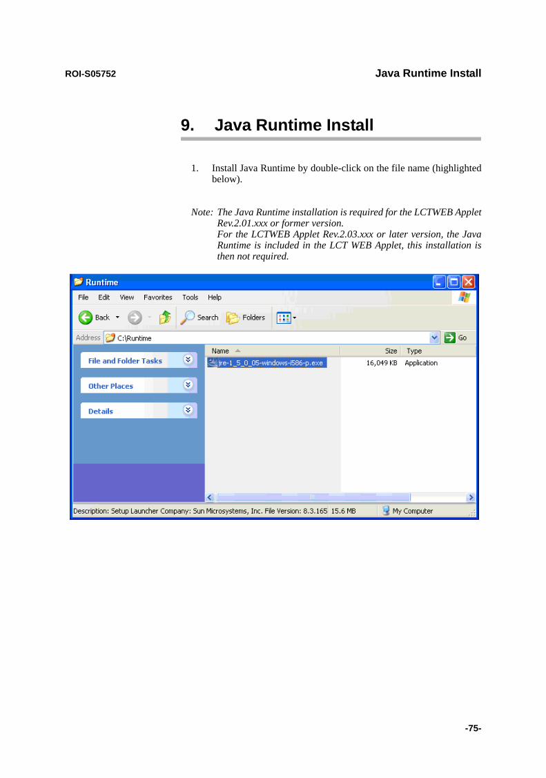
ROI-S05752 Java Runtime Install
-75-
9. Java Runtime Install
1. Install Java Runtime by double-click on the file name (highlighted below).
Note: The Java Runtime installation is required for the LCTWEB Applet Rev.2.01.xxx or former version. For the LCTWEB Applet Rev.2.03.xxx or later version, the Java Runtime is included in the LCT WEB Applet, this installation is then not required.
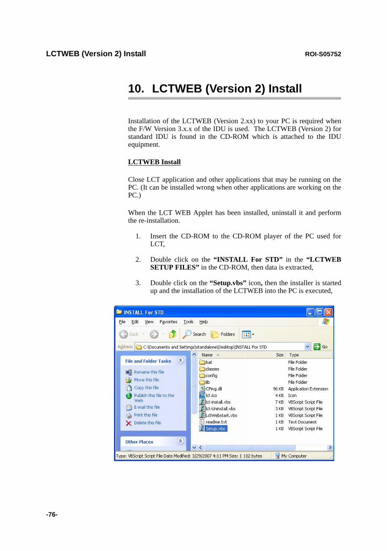
LCTWEB (Version 2) Install ROI-S05752
-76-
10. LCTWEB (Version 2) Install
Installation of the LCTWEB (Version 2.xx) to your PC is required when the F/W Version 3.x.x of the IDU is used. The LCTWEB (Version 2) for standard IDU is found in the CD-ROM which is attached to the IDU equipment.
LCTWEB Install
Close LCT application and other applications that may be running on the PC. (It can be installed wrong when other applications are working on the PC.)
When the LCT WEB Applet has been installed, uninstall it and perform the re-installation.
1. Insert the CD-ROM to the CD-ROM player of the PC used for LCT,
2. Double click on the “INSTALL For STD” in the “LCTWEB SETUP FILES” in the CD-ROM, then data is extracted,
3. Double click on the “Setup.vbs” icon, then the installer is started up and the installation of the LCTWEB into the PC is executed,

ROI-S05752 LCTWEB (Version 2) Install
-77-
4. Click on the “OK” button, when following prompt appears,
5. Click on the “OK” button in the prompt after the installation has been completed,
Following short-cut icon is made on the desktop,
6. Click on the short-cut icon or select the “Programs” → “NEC_ LCT” → “LCT For STD” from the “start” menu,

LCTWEB (Version 2) Install ROI-S05752
-78-
7. The LCTWEB is started up and “Login” dialog appears,
8. Confirm that the LCTWEB Version is “Rev. 2.xx.xxx” (for STD).
Rev.2.xx.xxx (for STD)

ROI-S05752 LCTWEB (Version 2) Install
-79-
LCTWEB Uninstall
Close LCT application and other applications that may be running on the PC. (It can be uninstalled wrong when other applications are working on the PC.)
1. Select the “Programs” → “NEC_ LCT” → “Uninstall LCT For STD” from the “start” menu for uninstall LCTWEB,
2. Click on the “OK” button, when following prompt appears,

LCTWEB (Version 2) Install ROI-S05752
-80-80 pages
3. Click on the “OK” button, when following prompt appears,
4. Uninstall finishes.
ROI-S05751-05CE CONTENTS August, 2007
CL-1
NLITE E 6-38 GHz SONET DIGITAL RADIO SYSTEM
Section IV MAINTENANCE
CONTENTS
TITLE PAGE
1 GENERAL ••••••••••••••••••••••••••••••••••••••••••••••••••••••••••••• 1-12 PRECAUTIONS •••••••••••••••••••••••••••••••••••••••••••••••••••••• 2-13 TEST SETS AND ACCESSORIES••••••••••••••••••••••••••••••• 3-14 ROUTINE MAINTENANCE •••••••••••••••••••••••••••••••••••••••• 4-14.1 Meter Reading ••••••••••••••••••••••••••••••••••••••••••••••••••• 4-14.2 Performance Monitoring•••••••••••••••••••••••••••••••••••••• 4-25 CORRECTIVE MAINTENANCE •••••••••••••••••••••••••••••••••• 5-15.1 Alarm/Status ••••••••••••••••••••••••••••••••••••••••••••••••••••• 5-15.1.1 Alarm and Status ••••••••••••••••••••••••••••••••••••••••••••••• 5-2
5.1.2 Control Item•••••••••••••••••••••••••••••••••••••••••••••••••••••• 5-9
5.1.3 Loopback •••••••••••••••••••••••••••••••••••••••••••••••••••••••• 5-12
5.1.4 BER Measurement •••••••••••••••••••••••••••••••••••••••••••• 5-17
5.1.5 Trouble Shooting Flow••••••••••••••••••••••••••••••••••••••• 5-21
5.2 Replacement •••••••••••••••••••••••••••••••••••••••••••••••••••• 5-245.2.1 ODU Replacement••••••••••••••••••••••••••••••••••••••••••••• 5-24
5.2.2 IDU and Module Replacement•••••••••••••••••••••••••••••• 5-30
5.2.3 Fuse Replacement •••••••••••••••••••••••••••••••••••••••••••• 5-51

ROI-S05751 GENERAL
1-1
1. GENERAL
This section provides instructions for maintenance of the NLITE E used for 6-38 GHz SONET microwave radio system.
This section provides instructions on the precautions, test setup and accessories, routine maintenance, corrective maintenance and mounting of optional modules.

ROI-S05751 PRECAUTIONS
2-1
2. PRECAUTIONS
The following precautions must be carefully observed during maintenance.
(a) The maintenance personnel should report arrival and departure from a station to the relevant station. The following are dangers and warnings to the maintenance personnel.
Warning: 1. The –48 V DC power is superimposed on the centre conductor of the coaxial cable between the IDU and the ODU. Connecting test equipment directly to this terminal may damage it and touching the coaxial cable core may cause electrical shock.
2. Persons performing maintenance must take necessary steps to avoid Electro-static Discharge (ESD) which may damage the modules on the IDU or cause error. Wear a conductive wrist strap connected to the grounded (G) jack on the front of the equipment shelf. This will minimize static build-up during maintenance. (see Fig. 2-1).
3. Do not remove/connect the IF cable with the IDU power ON. Turn the IDU power OFF before connecting/disconnecting the IF cable, or equipment may be damaged.
4. After turning ON the equipment, wait at least 1 minute before turning it OFF again. Repeatedly turning the power ON and OFF within a short interval may cause the IDU to fail.
5. Do not allow open or short circuit of ODU TX output with the TX power on conditions. Perform the TX Mute control in the Maintenance mode or turn the PWR switch off at the IDU before disconnecting cable or feeder from the ODU TX output.
6. Contact NEC before program download on the LCT is performed. Equipment may not function correctly with improper operation.
Caution: 1. In a system using the OPTICAL OC-3 INTFC, do not stare at the laser beam or look at it directly with optical instruments. Otherwise, it may hurt your eyes (Class 1 Laser Product).
2. The top surface of the IDU above MODEM is hot in operation.
3. When replacing the MODEM, OC-3 INTFC, or DC-DC CONV (optional) turn off the PWR switch and disconnect all cables connected to the module which is to be replaced.
(b) During maintenance, the IDU should be set to Maintenance “On” condition by the local craft terminal (LCT).

PRECAUTIONS ROI-S05751
2-2
(c) To avoid traffic interruption, under the maintenance, perform TX/RX SW manual switching in 1+1 system,.
Note: When TX/RX SW has been automatically switched during a fault, keep this condition by manual switching operation.
(d) While the CPU is initialized by the CPU RESET switch, alarm(s) status is reset to normal. After initialization, the alarm information is properly provided through relay contacts.
(e) Information on the maintenance and the control such as Mute, CW, LB, etc. is released if the power is turned off.
(f) If each setup item of “Equipment Setup” or “Provisioning” is changed during in operation, traffic will be momentarily interrupted.
(g) When the TX SW is activated, momentary traffic interruption may occurs.
(h) Before removing or installing the IDU/ODU, turn off the power switch on the MODEM.
(i) After completing maintenance, restore all connections, manual control settings to normal and confirm that all alarm LEDs are unlit.
(j) When replacing the MODEM, OC-3 INTFC, or E3 INTFC with spare, disconnect every cables connected to the module which is to be replaced, then turn off the power switch on the MODEM, surely.
(k) After equipment start-up, allow the equipment to warm up at least 30 minutes.
(l) In the XPIC system, polarization for the Main Master and Sub Master channel must be coincided between the local station and the opposite station.
(m) In the XPIC system, when the MODEM or ODU is replaced, set the XPIC Control Local and XPIC Control Remote to Forced Reset for the channel to be used for online.

Caution
Tighten the TNC-male connector of IF cable to the IDU with engage connector nut only using fingers and holding the cable with another hand.
Tighten the engage connector nut only for the L-angle connector also.
(Tightening Torque : 0.3 to 0.5 N•m (3 to 5kg•cm))
IDU
IDU
IF CABLE
IF CABLE
IDU
IF CABLE
Straight Type
L-Angle Type
L Angle Type
If rotate other parts of the L-angle connector as illustrated left, it can cause connector damage.
ROI-S05751 PRECAUTIONS
2-3

PRECAUTIONS ROI-S05751
2-4
Chart 2-1 Wrist Strap Connection
Step Procedure
1 Connect the wrist strap to the ESD ground terminal (G),
1+0 SYSTEM
1+1 SYSTEM IDU
G
G
SELV
!
AUX/ALMLCT NMS NE SC IN/OUT EOW
PROTECT
CALL MMC
MAINTMEMORY
IDU
XIF IN XIF OUT
IF IN/OUTTXRX
RESETXPIC CTRLXPIC
PWRODUMD/CBL PWR
PASOLINK NEO
PULL
(Blank)
GG
G
SELV
!
AUX/ALMLCT NMS NE SC IN/OUT EOW
PROTECT
CALL MMC
MAINTMEMORY
IDU
XIF IN XIF OUT
IF IN/OUTTXRX
RESETXPIC CTRLXPIC
PWRODUMD/CBL PWR
PASOLINK NEO
PULL
SELV
!
XIF IN XIF OUT
IF IN/OUTTXRX
RESETXPIC CTRLXPIC
PWRODUMD/CBL PWR
PULL
GG
G
G
G
G
IDU
ALM
OC-3 INOC-3 OUTALM
OC-3 INOC-3 OUT ONLINEONLINE
ALM
OC-3 INOC-3 OUTALM
OC-3 INOC-3 OUT ONLINEONLINE
Fig. 2-1 ESD Ground Terminal Location
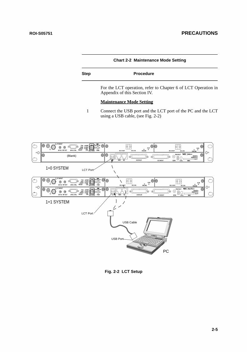
ROI-S05751 PRECAUTIONS
2-5
Chart 2-2 Maintenance Mode Setting
Step Procedure
For the LCT operation, refer to Chapter 6 of LCT Operation in Appendix of this Section IV.
Maintenance Mode Setting
1 Connect the USB port and the LCT port of the PC and the LCT using a USB cable, (see Fig. 2-2)
PC
USB Cable
1+0 SYSTEM
1+1 SYSTEM
SELV
!
AUX/ALMLCT NMS NE SC IN/OUT EOW
PROTECT
CALL MMC
MAINTMEMORY
IDU
XIF IN XIF OUT
IF IN/OUTTXRX
RESETXPIC CTRLXPIC
PWRODUMD/CBL PWR
nlite e
PULL
(Blank)
G
G
G
SELV
!
AUX/ALMLCT NMS NE SC IN/OUT EOW
PROTECT
CALL MMC
MAINTMEMORY
IDU
XIF IN XIF OUT
IF IN/OUTTXRX
RESETXPIC CTRLXPIC
PWRODUMD/CBL PWR
NLITE 3
PULL
SELV
!
XIF IN XIF OUT
IF IN/OUTTXRX
RESETXPIC CTRLXPIC
PWRODUMD/CBL PWR
PULL
GG
G
G
LCT Port
USB Port
LCT Port
ALM
OC-3 INOC-3 OUTALM
OC-3 INOC-3 OUT ONLINEONLINE
ALM
OC-3 INOC-3 OUTALM
OC-3 INOC-3 OUT ONLINEONLINE
Fig. 2-2 LCT Setup
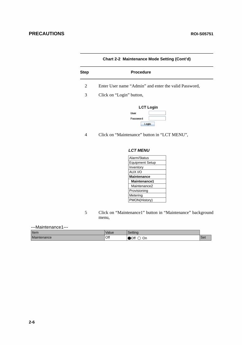
PRECAUTIONS ROI-S05751
2-6
Chart 2-2 Maintenance Mode Setting (Cont’d)
Step Procedure
2 Enter User name “Admin” and enter the valid Password,
3 Click on “Login” button,
4 Click on “Maintenance” button in “LCT MENU”,
LCT MENU
Alarm/StatusEquipment SetupInventoryAUX I/OMaintenance Maintenance1 Maintenance2ProvisioningMeteringPMON(History)
5 Click on “Maintenance1” button in “Maintenance” background menu,
---Maintenance1---Item Value SettingMaintenance Off Off On Set
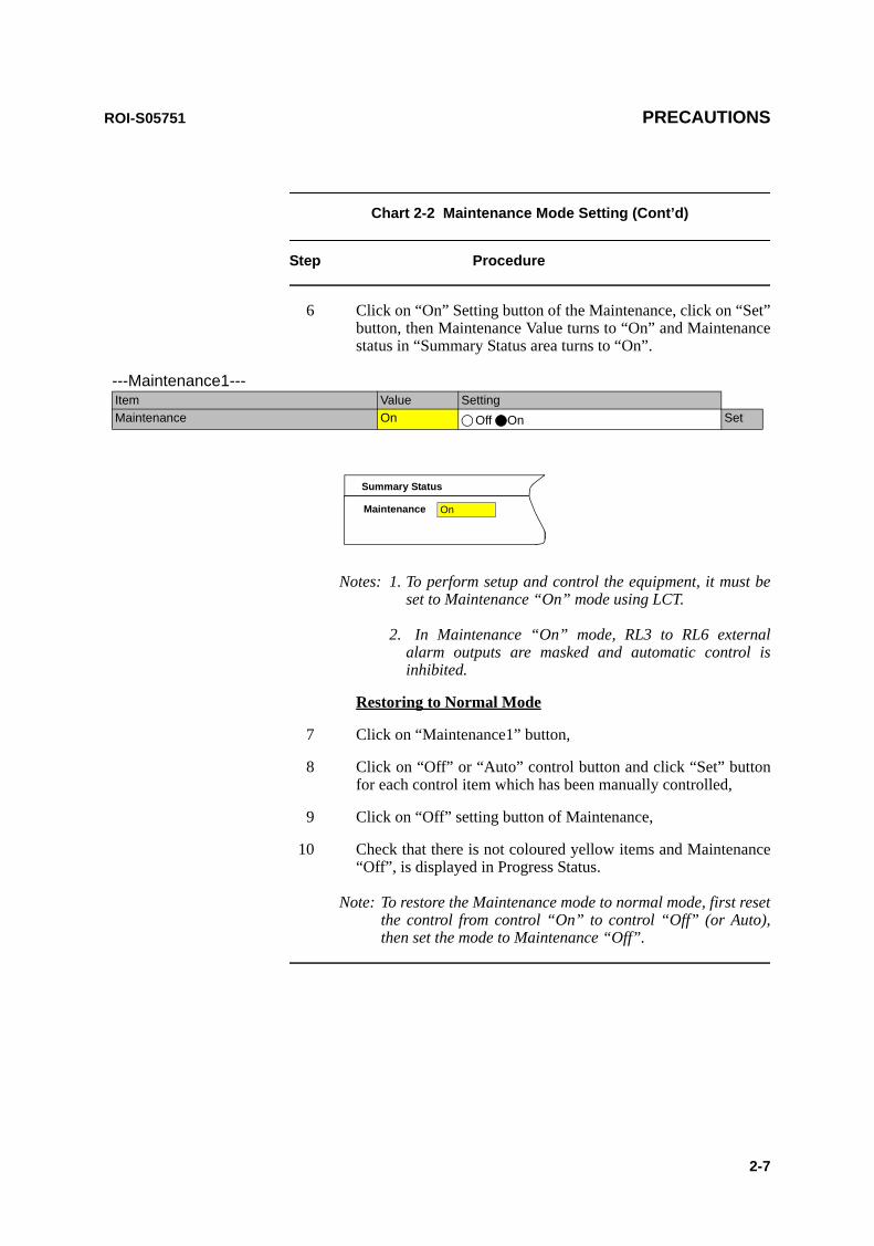
ROI-S05751 PRECAUTIONS
2-7
Chart 2-2 Maintenance Mode Setting (Cont’d)
Step Procedure
6 Click on “On” Setting button of the Maintenance, click on “Set” button, then Maintenance Value turns to “On” and Maintenance status in “Summary Status area turns to “On”.
Maintenance On
Summary Status
Notes: 1. To perform setup and control the equipment, it must be set to Maintenance “On” mode using LCT.
2. In Maintenance “On” mode, RL3 to RL6 external alarm outputs are masked and automatic control is inhibited.
Restoring to Normal Mode
7 Click on “Maintenance1” button,
8 Click on “Off” or “Auto” control button and click “Set” button for each control item which has been manually controlled,
9 Click on “Off” setting button of Maintenance,
10 Check that there is not coloured yellow items and Maintenance “Off”, is displayed in Progress Status.
Note: To restore the Maintenance mode to normal mode, first reset the control from control “On” to control “Off” (or Auto), then set the mode to Maintenance “Off”.
---Maintenance1---Item Value SettingMaintenance On Off On Set

PRECAUTIONS ROI-S05751
2-8
Chart 2-3 Manual Switchover Operation (only 1+1Configuration)
Step Procedure
For the LCT operation, refer to Chapter 6 of LCT Operation in Appendix of this Section IV.
1 Connect the USB port and the LCT port of the PC and the LCT using a USB cable, (see Fig. 2-2)
2 Login to the LCT with User name “Admin” and Admin “Password”,
3 Click on “Maintenance” button in “LCT MENU” and click on “Maintenance1” button in Maintenance background menu,
Note: Control items can be performed only when the MAINT mode is “On”.
Note: Control items displayed on the LCT vary depending on system configuration.
4 Click on TX SW and/or RX SW to desired “No.1”, “No.2” or “Auto” button,
5 Click on “Set” button,
6 After test has been completed, set the TX SW and RX SW to “Auto” position,
7 Set maintenance mode to “Off” according to Chart 2-2.
---Maintenance1---Item Value SettingMaintenance On Off On SetTX SW Manual Control No.1 Auto No.1 No.2 SetRX SW Manual Control Auto Auto No.1 No.2 Set

ROI-S05751 PRECAUTIONS
2-9
Chart 2-4 APS Manual Switchover Operation(only APS Configuration in SONET)
Step Procedure
For the LCT operation, refer to Chapter 6 of LCT Operation in Appendix of this Section IV.
1 Connect the USB port and the LCT port of the PC and the LCT using a USB cable, (see Fig. 2-2)
2 Login to the LCT with User name “Admin” and Admin “Password”,
3 Click on “Maintenance” button in “LCT MENU” and click on “Maintenance1” button in Maintenance background menu,
Note: Control items can be performed only when the MAINT mode is “On”.
Note: Control items displayed on the LCT vary depending on system configuration.
4 Click on desired “Auto”, “Working” or “Protection” button,
5 Click on “Set” button,
6 After test has been completed, set the APS Manual control to “Auto” position,
7 Set maintenance mode to “Off” according to Chart 2-2.
---Maintenance1---Item Value SettingMaintenance On Off On SetAPS Manual Control Working Auto Working Protection SetAPS Maintenance Mode Manual

PRECAUTIONS ROI-S05751
2-1010 pages
(This page is intentionally left blank.)

ROI-S05751 TEST SETS AND ACCESSORIES
3-1
3. TEST SETS AND ACCESSORIES
The test sets and special accessories listed in Table 3-1 are required for maintenance. If recommended test sets and accessories are not available, equivalents may be used.
Table 3-1 Test Sets and Accessories
No. Model Type Model Number Manufacture
1 SONET Analyzer MP1570A ANRITSU
2 Optical Variable Attenuator MN95D ANRITSU
3 Digital Multimeter 34401A Agilent
4 Screwdriver — —
5 T Type Hexagonal Driver — —
6 Torque Wrench — —
7 PC for Local Craft Terminal (LCT)** — —
Notes:1. * The NLite E Monitor operates on a dry battery (6F22/9V). When the NLite E Monitor will not be used for a long period, remove the battery to avoid damage from battery leakage and corrosion.
2. ** Refer LCT Operation in Appendix in this Section IV.

TEST SETS AND ACCESSORIES ROI-S05751
3-2
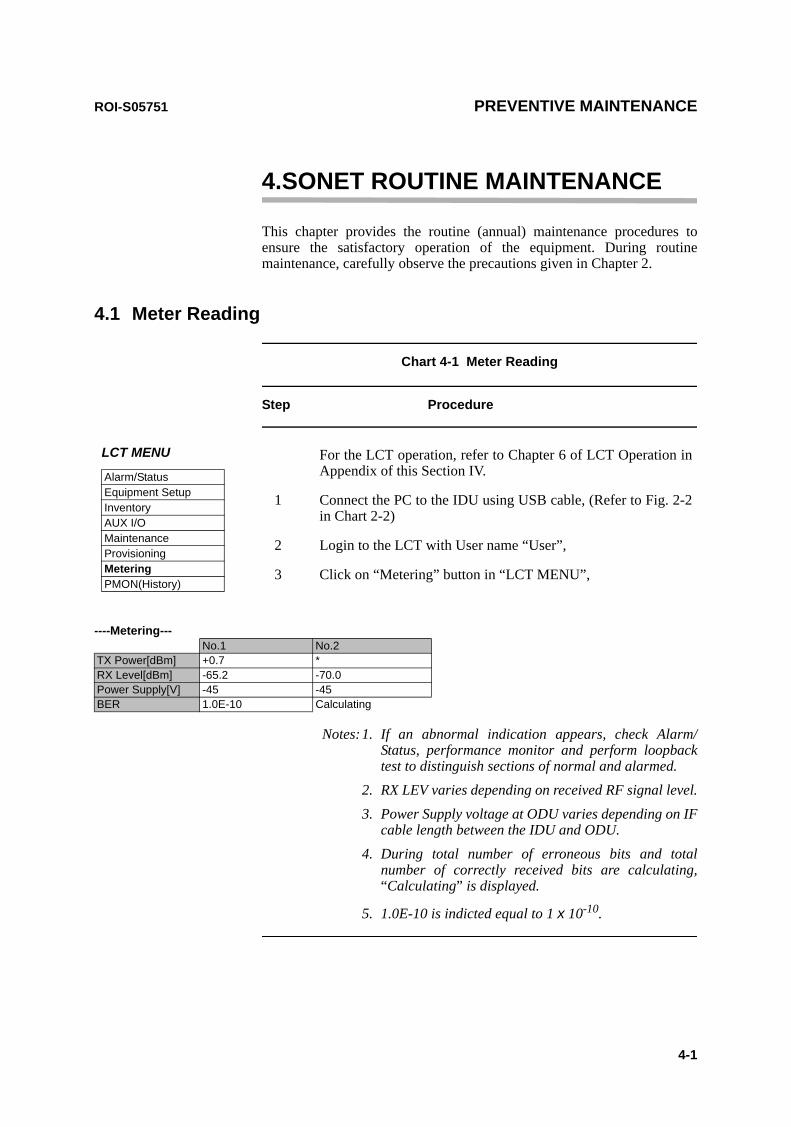
ROI-S05751 PREVENTIVE MAINTENANCE
4-1
4.SONET ROUTINE MAINTENANCE
This chapter provides the routine (annual) maintenance procedures to ensure the satisfactory operation of the equipment. During routinemaintenance, carefully observe the precautions given in Chapter 2.
4.1 Meter Reading
Chart 4-1 Meter Reading
Step Procedure
Notes:1. If an abnormal indication appears, check Alarm/Status, performance monitor and perform loopback test to distinguish sections of normal and alarmed.
2. RX LEV varies depending on received RF signal level.3. Power Supply voltage at ODU varies depending on IF
cable length between the IDU and ODU.4. During total number of erroneous bits and total
number of correctly received bits are calculating, “Calculating” is displayed.
5. 1.0E-10 is indicted equal to 1 x 10⁻¹⁰.
----Metering---No.1 No.2
TX Power[dBm] +0.7 *RX Level[dBm] -65.2 -70.0Power Supply[V] -45 -45BER 1.0E-10 Calculating
LCT MENU
Alarm/StatusEquipment SetupInventoryAUX I/OMaintenanceProvisioningMeteringPMON(History)
For the LCT operation, refer to Chapter 6 of LCT Operation in Appendix of this Section IV.
1 Connect the PC to the IDU using USB cable, (Refer to Fig. 2-2 in Chart 2-2)
2 Login to the LCT with User name “User”,
3 Click on “Metering” button in “LCT MENU”,
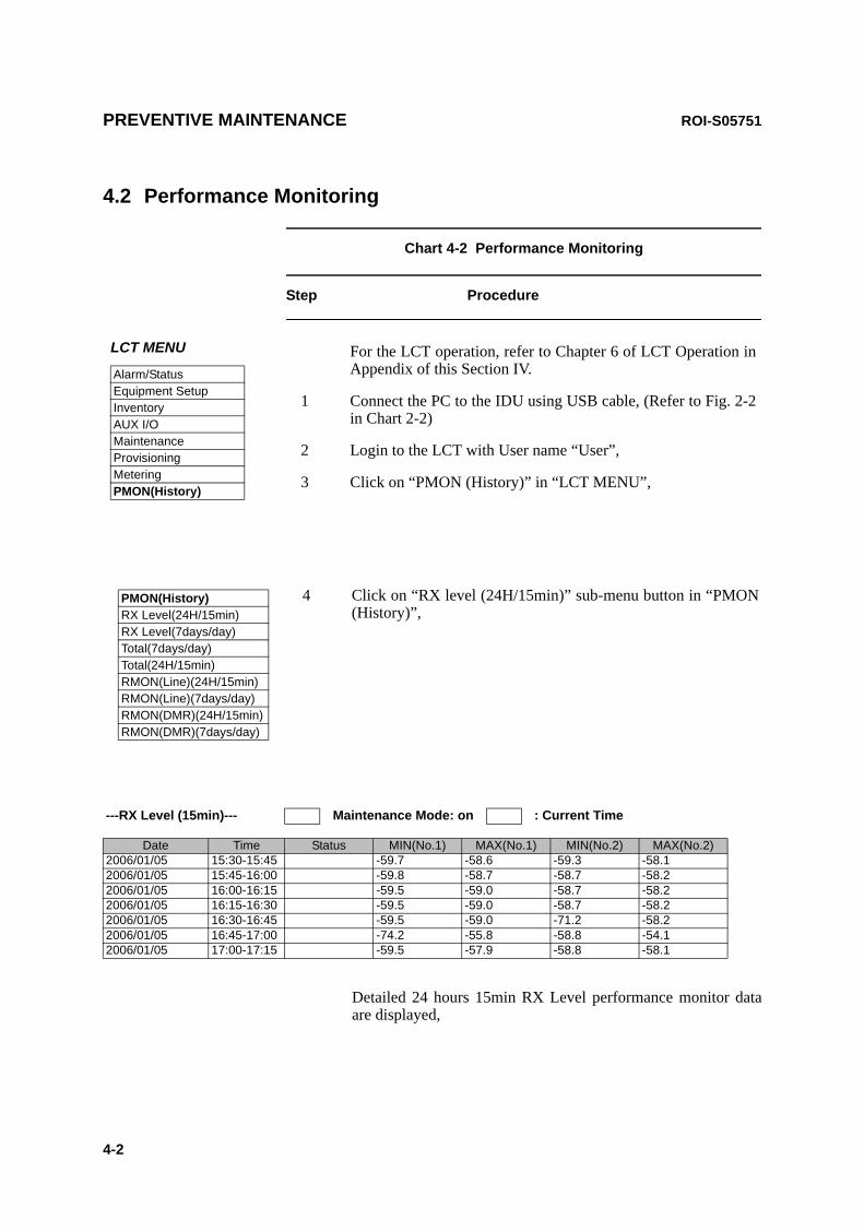
PREVENTIVE MAINTENANCE ROI-S05751
4-2
4.2 Performance Monitoring
Chart 4-2 Performance Monitoring
Step Procedure
Detailed 24 hours 15min RX Level performance monitor data are displayed,
---RX Level (15min)--- Maintenance Mode: on : Current Time
Date Time Status MIN(No.1) MAX(No.1) MIN(No.2) MAX(No.2)2006/01/05 15:30-15:45 -59.7 -58.6 -59.3 -58.12006/01/05 15:45-16:00 -59.8 -58.7 -58.7 -58.22006/01/05 16:00-16:15 -59.5 -59.0 -58.7 -58.22006/01/05 16:15-16:30 -59.5 -59.0 -58.7 -58.22006/01/05 16:30-16:45 -59.5 -59.0 -71.2 -58.22006/01/05 16:45-17:00 -74.2 -55.8 -58.8 -54.12006/01/05 17:00-17:15 -59.5 -57.9 -58.8 -58.1
LCT MENU
Alarm/StatusEquipment SetupInventoryAUX I/OMaintenanceProvisioningMeteringPMON(History)
For the LCT operation, refer to Chapter 6 of LCT Operation in Appendix of this Section IV.
1 Connect the PC to the IDU using USB cable, (Refer to Fig. 2-2 in Chart 2-2)
2 Login to the LCT with User name “User”,
3 Click on “PMON (History)” in “LCT MENU”,
PMON(History)RX Level(24H/15min)RX Level(7days/day)Total(7days/day)Total(24H/15min)RMON(Line)(24H/15min)RMON(Line)(7days/day)RMON(DMR)(24H/15min)RMON(DMR)(7days/day)
4 Click on “RX level (24H/15min)” sub-menu button in “PMON (History)”,

ROI-S05751 PREVENTIVE MAINTENANCE
4-3
Chart 4-2 (Cont’d)
Step Procedure
5 Click on “RX level (7days/day)” sub-menu button in “PMON (History)”,
Detailed 7days daily RX Level performance monitor data are displayed,
6 Click on “Total(24H/15min)” sub-menu button in “PMON (History)”,
Detailed 24 hours 15min Total performance data are displayed.
7 Click on “Total(7days/day)” sub-menu button in “PMON (History)”,
---RX Level (day)--- Maintenance Mode: on
Date Status MIN(No.1) MAX(No.1) MIN(No.2) MAX(No.2)2006/01/01 -59.7 -58.6 -59.3 -58.12006/01/02 -59.8 -58.7 -58.7 -58.22006/01/03 -59.5 -59.0 -58.7 -58.22006/01/04 -59.5 -59.0 -58.7 -58.22006/01/05 -59.5 -59.0 -71.2 -58.22006/01/06 -74.2 -55.8 -58.8 -54.12006/01/07 -59.5 -57.9 -58.8 -58.1
---Total(15min)---- Maintenance Mode: on : Current Time
Date Time Status OFS SEP BBE ES SES UAS2006/01/05 15:30-15:45 0 0 0 0 0 02006/01/05 15:45-16:00 0 0 0 0 0 02006/01/05 16:00-16:15 0 0 0 0 0 02006/01/05 16:15-16:30 0 0 0 0 0 02006/01/05 16:30-16:45 0 0 0 0 0 02006/01/05 16:45-17:00 0 0 0 0 0 02006/01/05 17:00-17:15 0 0 0 0 0 0

PREVENTIVE MAINTENANCE ROI-S05751
4-4
Chart 4-2 (Cont’d)
Step Procedure
Detailed 7days daily total performance monitor data are displayed,
8 Click on “RMON(Line)(24H/15min)” sub-menu button in “PMON (History)”,
Detailed 24 hours 15min Line (LAN) RMON (Remote Network Monitoring) data are displayed.
---Total(1day)--- Maintenance Mode: on
Date Status OFS SEP BBE ES SES UAS2006/01/01 0 0 0 0 0 02006/01/02 0 0 0 0 0 02006/01/03 0 0 0 0 0 02006/01/04 0 0 0 0 0 02006/01/05 0 0 0 0 0 02006/01/06 0 0 0 0 0 02006/01/07 0 0 0 0 0 0
---RMON(Line)(15min)--- Maintenance Mode: on : Current Time
Port1
Date Time Status 1 2 3 4 52006/01/05 00:00-00:15 1:
2:3:4:5:6:7:8:9:10:11:12:13:14:15:16:17:18:19:20:21:22:
RX UNICASTRX BROADCASTRX MULTICASTRX PAUSERX CEC ERRRX ALIGNMENT ERRRX SYMBOL ERRRX UNDERSIZERX FRAGMENTSRX 64RX 65-127RX 128-255RX 256-511RX 512-1023RX 1024-1536RX 1537-MAXRX JABBERSTX UNICASTTX BROADCASTTX MULTICASTTX PAUSETX COLLISION
2006/01/05 00:15-00:302006/01/05 00:30-00:452006/01/05 00:45-01:002006/01/05 01:00-01:152006/01/05 01:15-01:302006/01/05 01:30-01:452006/01/05 01:45-02:002006/01/05 02:00-02:152006/01/05 02:15-02:302006/01/05 02:30-02:452006/01/05 02:45-03:002006/01/05 03:00-03:152006/01/05 03:15-03:302006/01/05 03:30-03:452006/01/05 03:45-04:002006/01/05 04:00-04:152006/01/05 04:15-04:302006/01/05 04:30-04:452006/01/05 04:45-05:002006/01/05 05:00-05:15

ROI-S05751 PREVENTIVE MAINTENANCE
4-5
Chart 4-2 (Cont’d)
Step Procedure
9 Click on “RMON(Line)(7days/day)” sub-menu button in “PMON (History)”,
Detailed daily Line (LAN) RMON (Remote Network Monitoring) data are displayed.
---RMON(Line)(1day)--- Maintenance Mode: on
Port1
Date Time Status 1 2 3 4 5 61:2:3:4:5:6:7:8:9:10:11:12:13:14:15:16:17:18:19:20:21:22:
RX UNICASTRX BROADCASTRX MULTICASTRX PAUSERX CEC ERRRX ALIGNMENT ERRRX SYMBOL ERRRX UNDERSIZERX FRAGMENTSRX 64RX 65-127RX 128-255RX 256-511RX 512-1023RX 1024-1536RX 1537-MAXRX JABBERSTX UNICASTTX BROADCASTTX MULTICASTTX PAUSETX COLLISION

PREVENTIVE MAINTENANCE ROI-S05751
4-6
Chart 4-2 (Cont’d)
Step Procedure
10 Click on “RMON(DMR)(24H/15min)” sub-menu button in “PMON (History)”,
Detailed 15 minutes DMR (LAN) RMON (Remote Network Monitoring) data are displayed.
---RMON(DMR)(15min)--- Maintenance Mode: on : Current Time
Port1
Date Time Status 1 2 3 4 52006/01/05 00:00-00:15 1:
2:3:4:5:6:7:8:9:10:11:12:13:14:15:16:17:18:
RX UNICASTRX BROADCASTRX MULTICASTRX PAUSERX CEC ERRRX FRAGMENTSRX 64RX 65-127RX 128-255RX 256-511RX 512-1023RX 1024-1536RX 1537-MAXRX JABBERSTX UNICASTTX BROADCASTTX MULTICASTTX PAUSE
2006/01/05 00:15-00:302006/01/05 00:30-00:452006/01/05 00:45-01:002006/01/05 01:00-01:152006/01/05 01:15-01:302006/01/05 01:30-01:452006/01/05 01:45-02:002006/01/05 02:00-02:152006/01/05 02:15-02:302006/01/05 02:30-02:452006/01/05 02:45-03:002006/01/05 03:00-03:152006/01/05 03:15-03:302006/01/05 03:30-03:452006/01/05 03:45-04:00

ROI-S05751 PREVENTIVE MAINTENANCE
4-7
Chart 4-2 (Cont’d)
Step Procedure
11 Click on “RMON(DMR)(7days/day)” sub-menu button in “PMON (History)”,
Detailed daily DMR (LAN) RMON (Remote Network Monitoring) data are displayed.
---RMON(DMR)(1day)--- Maintenance Mode: on
Port1
Date Time Status 1 2 3 4 5 61:2:3:4:5:6:7:8:9:10:11:12:13:14:15:16:17:18:
RX UNICASTRX BROADCASTRX MULTICASTRX PAUSERX CEC ERRRX FRAGMENTSRX 64RX 65-127RX 128-255RX 256-511RX 512-1023RX 1024-1536RX 1537-MAXRX JABBERSTX UNICASTTX BROADCASTTX MULTICASTTX PAUSE
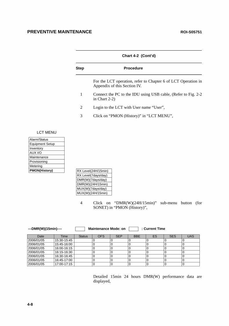
PREVENTIVE MAINTENANCE ROI-S05751
4-8
Chart 4-2 (Cont’d)
Step Procedure
For the LCT operation, refer to Chapter 6 of LCT Operation in Appendix of this Section IV.
1 Connect the PC to the IDU using USB cable, (Refer to Fig. 2-2 in Chart 2-2)
2 Login to the LCT with User name “User”,
3 Click on “PMON (History)” in “LCT MENU”,
4 Click on “DMR(W)(24H/15min)” sub-menu button (for SONET) in “PMON (History)”,
Detailed 15min 24 hours DMR(W) performance data are displayed,
LCT MENU
Alarm/StatusEquipment SetupInventoryAUX I/OMaintenanceProvisioningMeteringPMON(History) RX Level(24H/15min)
RX Level(7days/day)DMR(W)(7days/day)DMR(W)(24H/15min)MUX(W)(7days/day)MUX(W)(24H/15min)
---DMR(W)(15min)---- Maintenance Mode: on : Current Time
Date Time Status OFS SEP BBE ES SES UAS2006/01/05 15:30-15:45 0 0 0 0 0 02006/01/05 15:45-16:00 0 0 0 0 0 02006/01/05 16:00-16:15 0 0 0 0 0 02006/01/05 16:15-16:30 0 0 0 0 0 02006/01/05 16:30-16:45 0 0 0 0 0 02006/01/05 16:45-17:00 0 0 0 0 0 02006/01/05 17:00-17:15 0 0 0 0 0 0
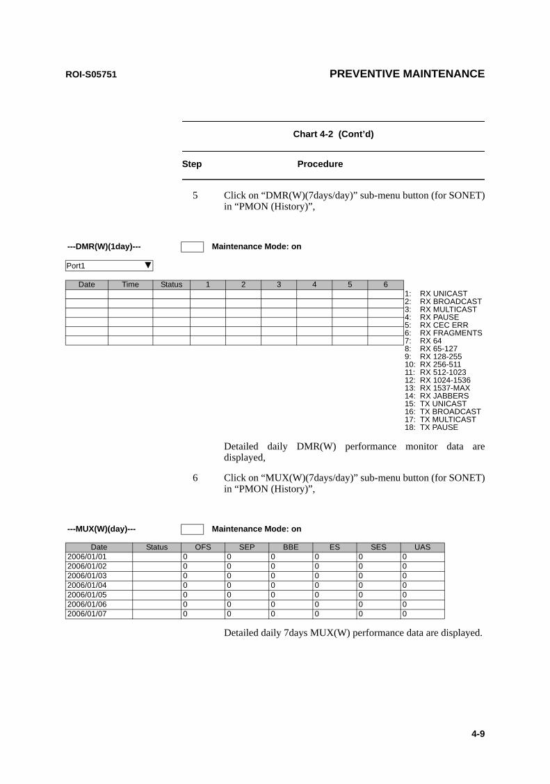
ROI-S05751 PREVENTIVE MAINTENANCE
4-9
Chart 4-2 (Cont’d)
Step Procedure
5 Click on “DMR(W)(7days/day)” sub-menu button (for SONET) in “PMON (History)”,
Detailed daily DMR(W) performance monitor data are displayed,
6 Click on “MUX(W)(7days/day)” sub-menu button (for SONET) in “PMON (History)”,
Detailed daily 7days MUX(W) performance data are displayed.
---DMR(W)(1day)--- Maintenance Mode: on
Port1
Date Time Status 1 2 3 4 5 61:2:3:4:5:6:7:8:9:10:11:12:13:14:15:16:17:18:
RX UNICASTRX BROADCASTRX MULTICASTRX PAUSERX CEC ERRRX FRAGMENTSRX 64RX 65-127RX 128-255RX 256-511RX 512-1023RX 1024-1536RX 1537-MAXRX JABBERSTX UNICASTTX BROADCASTTX MULTICASTTX PAUSE
---MUX(W)(day)--- Maintenance Mode: on
Date Status OFS SEP BBE ES SES UAS2006/01/01 0 0 0 0 0 02006/01/02 0 0 0 0 0 02006/01/03 0 0 0 0 0 02006/01/04 0 0 0 0 0 02006/01/05 0 0 0 0 0 02006/01/06 0 0 0 0 0 02006/01/07 0 0 0 0 0 0
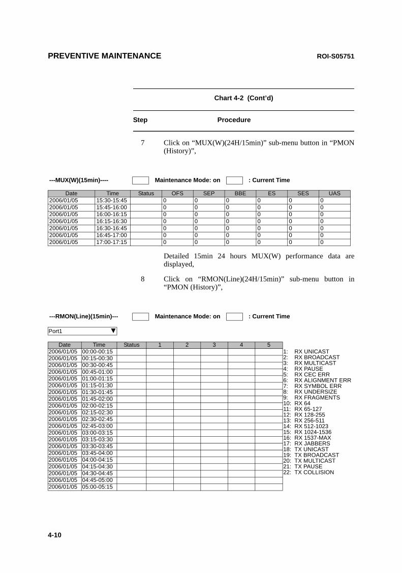
PREVENTIVE MAINTENANCE ROI-S05751
4-10
Chart 4-2 (Cont’d)
Step Procedure
7 Click on “MUX(W)(24H/15min)” sub-menu button in “PMON (History)”,
Detailed 15min 24 hours MUX(W) performance data are displayed,
8 Click on “RMON(Line)(24H/15min)” sub-menu button in “PMON (History)”,
---MUX(W)(15min)---- Maintenance Mode: on : Current Time
Date Time Status OFS SEP BBE ES SES UAS2006/01/05 15:30-15:45 0 0 0 0 0 02006/01/05 15:45-16:00 0 0 0 0 0 02006/01/05 16:00-16:15 0 0 0 0 0 02006/01/05 16:15-16:30 0 0 0 0 0 02006/01/05 16:30-16:45 0 0 0 0 0 02006/01/05 16:45-17:00 0 0 0 0 0 02006/01/05 17:00-17:15 0 0 0 0 0 0
---RMON(Line)(15min)--- Maintenance Mode: on : Current Time
Port1
Date Time Status 1 2 3 4 52006/01/05 00:00-00:15 1:
2:3:4:5:6:7:8:9:10:11:12:13:14:15:16:17:18:19:20:21:22:
RX UNICASTRX BROADCASTRX MULTICASTRX PAUSERX CEC ERRRX ALIGNMENT ERRRX SYMBOL ERRRX UNDERSIZERX FRAGMENTSRX 64RX 65-127RX 128-255RX 256-511RX 512-1023RX 1024-1536RX 1537-MAXRX JABBERSTX UNICASTTX BROADCASTTX MULTICASTTX PAUSETX COLLISION
2006/01/05 00:15-00:302006/01/05 00:30-00:452006/01/05 00:45-01:002006/01/05 01:00-01:152006/01/05 01:15-01:302006/01/05 01:30-01:452006/01/05 01:45-02:002006/01/05 02:00-02:152006/01/05 02:15-02:302006/01/05 02:30-02:452006/01/05 02:45-03:002006/01/05 03:00-03:152006/01/05 03:15-03:302006/01/05 03:30-03:452006/01/05 03:45-04:002006/01/05 04:00-04:152006/01/05 04:15-04:302006/01/05 04:30-04:452006/01/05 04:45-05:002006/01/05 05:00-05:15
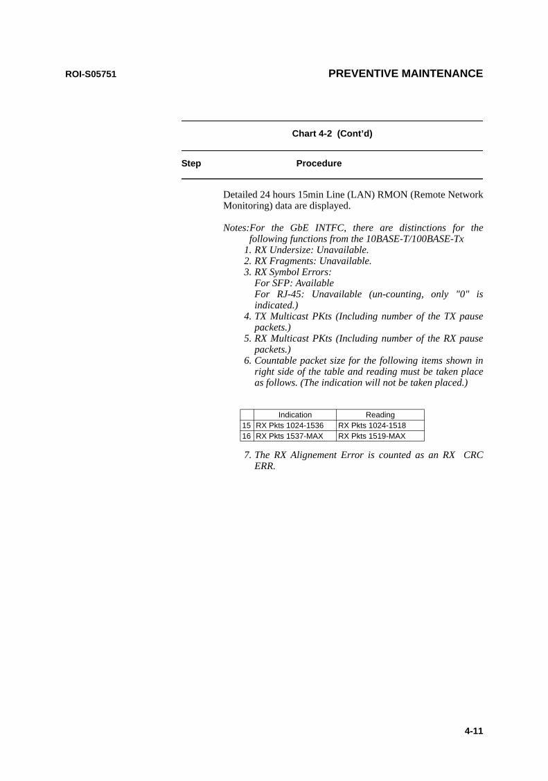
ROI-S05751 PREVENTIVE MAINTENANCE
4-11
Chart 4-2 (Cont’d)
Step Procedure
Detailed 24 hours 15min Line (LAN) RMON (Remote Network Monitoring) data are displayed.
Notes:For the GbE INTFC, there are distinctions for the following functions from the 10BASE-T/100BASE-Tx
1. RX Undersize: Unavailable.2. RX Fragments: Unavailable.3. RX Symbol Errors:
For SFP: Available For RJ-45: Unavailable (un-counting, only "0" is indicated.)
4. TX Multicast PKts (Including number of the TX pause packets.)
5. RX Multicast PKts (Including number of the RX pause packets.)
6. Countable packet size for the following items shown in right side of the table and reading must be taken place as follows. (The indication will not be taken placed.)
7. The RX Alignement Error is counted as an RX CRC ERR.
Indication Reading15 RX Pkts 1024-1536 RX Pkts 1024-151816 RX Pkts 1537-MAX RX Pkts 1519-MAX