Embed Size (px)
Citation preview
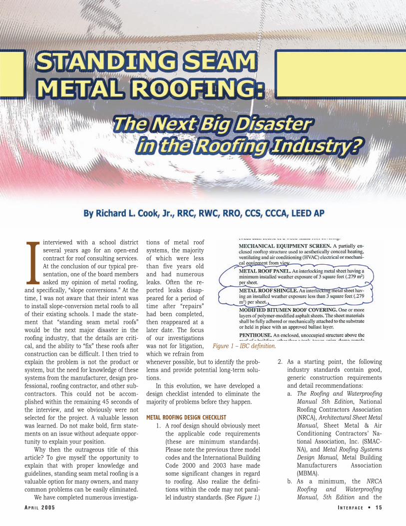
Iinterviewed with a school district several years ago for an open-end contract for roof consulting services. At the conclusion of our typical presentation, one of the board members asked my opinion of metal roofing,
and specifically, “slope conversions.” At the time, I was not aware that their intent was to install slope-conversion metal roofs to all of their existing schools. I made the statement that “standing seam metal roofs” would be the next major disaster in the roofing industry, that the details are critical, and the ability to “fix” these roofs after construction can be difficult. I then tried to explain the problem is not the product or system, but the need for knowledge of these systems from the manufacturer, design professional, roofing contractor, and other subcontractors. This could not be accomplished within the remaining 45 seconds of the interview, and we obviously were not selected for the project. A valuable lesson was learned. Do not make bold, firm statements on an issue without adequate opportunity to explain your position.
Why then the outrageous title of this article? To give myself the opportunity to explain that with proper knowledge and guidelines, standing seam metal roofing is a valuable option for many owners, and many common problems can be easily eliminated.
We have completed numerous investiga-
A P R I L 2 0 0 5
tions of metal roof systems, the majority of which were less than five years old and had numerous leaks. Often the reported leaks disappeared for a period of time after “repairs” had been completed, then reappeared at a later date. The focus of our investigations was not for litigation, Figure 1 – IBC definition. which we refrain from whenever possible, but to identify the prob 2. As a starting point, the following lems and provide potential long-term solu industry standards contain good, tions. generic construction requirements
In this evolution, we have developed a and detail recommendations: design checklist intended to eliminate the a. The Roofing and Waterproofing majority of problems before they happen. Manual 5th Edition, National
Roofing Contractors Association METAL ROOFING DESIGN CHECKLIST (NRCA), Architectural Sheet Metal
1. A roof design should obviously meet Manual, Sheet Metal & Air the applicable code requirements Conditioning Contractors’ Na(these are minimum standards). tional Association, Inc. (SMAC-Please note the previous three model NA), and Metal Roofing Systems codes and the International Building Design Manual, Metal Building Code 2000 and 2003 have made Manufacturers Association some significant changes in regard (MBMA). to roofing. Also realize the defini b. As a minimum, the NRCA tions within the code may not paral- Roofing and Waterproofing lel industry standards. (See Figure 1.) Manual, 5th Edition and the
I N T E R F A C E • 1 5
Standing Seam Metal Roofing (SSMR) Construction Details for both architectural and structural systems should be the basis for all design development. Specific, custom details will still be required for unique or special penetrations and project-specific terminations.
c. As a minimum, recommend adding the following to your general notes and specifications:
“All clarifications or additional information needed shall be in accordance with the criteria and details of the NRCA Roofing and Waterproofing Manual and the Architectural Sheet Metal Manual. Any deviation from the specified or indicated requirements shall be submitted for approval by the designer or owner’s representative prior to installation.”
3. Exposed fasteners in the flat of the roof panel, although commonly accepted or allowed by the manufacturer, should be avoided to the greatest extent possible. Exceptions do exist, especially in high wind zones.
4. The SMACNA Architectural Sheet Metal Manual, 6th Edition, is a good source for details and criteria for various sheet metal systems and components but requires specific needs to be identified for the job since various configurations exist for different components and are typically recommended versus required.
5. Do not write specifications that rely on or allow the manufacturer to determine the acceptability of a condition or the details to be used. The specifier’s design (details) should establish the minimum requirements. Proprietary specifications for contractors, suppliers, or manufacturers are also not recommended; neither are open specifications that everyone meets (i.e., typical ASTM specifications).
6. Clearly show sections of construction requirements for the roof assembly, including structural framing, deck, insulation, underlayment systems, and the transition
into the various terminations. a good indicator that improper 7. Metal does not leak; the penetra details are being used.
tions and terminations do. For this 8. Provide a new roof plan. Identify reason, specific custom details will slopes and indicate all penetrations still be required for penetrations and and terminations. Provide applicable terminations. Exposed sealants are details and references for the pene-
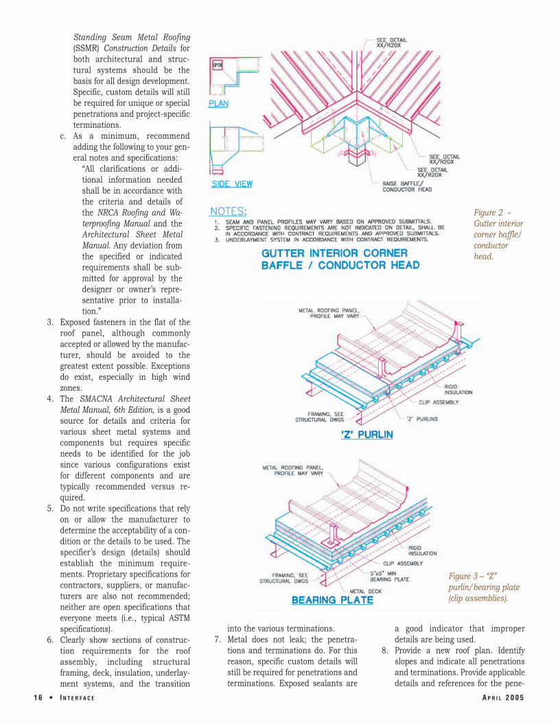
Figure 2 – Gutter interior corner baffle/ conductor head.
Figure 3 – “Z” purlin/bearing plate (clip assemblies).
1 6 • I N T E R F A C E A P R I L 2 0 0 5
trations and terminations. Isometric details are preferred.
9. For roof replacements and slope conversions, provide an “Existing Roof Plan,” identifying existing assemblies and locations of penetrations and terminations. Indicate which penetrations are to be abandoned and show on the “New Roof Plan” which penetrations are to extend through the SSMR.
10. For roof replacements and slope conversions, coordinate the “Existing Roof Plan” and “New Roof Plan” with the structural specifications and drawings.
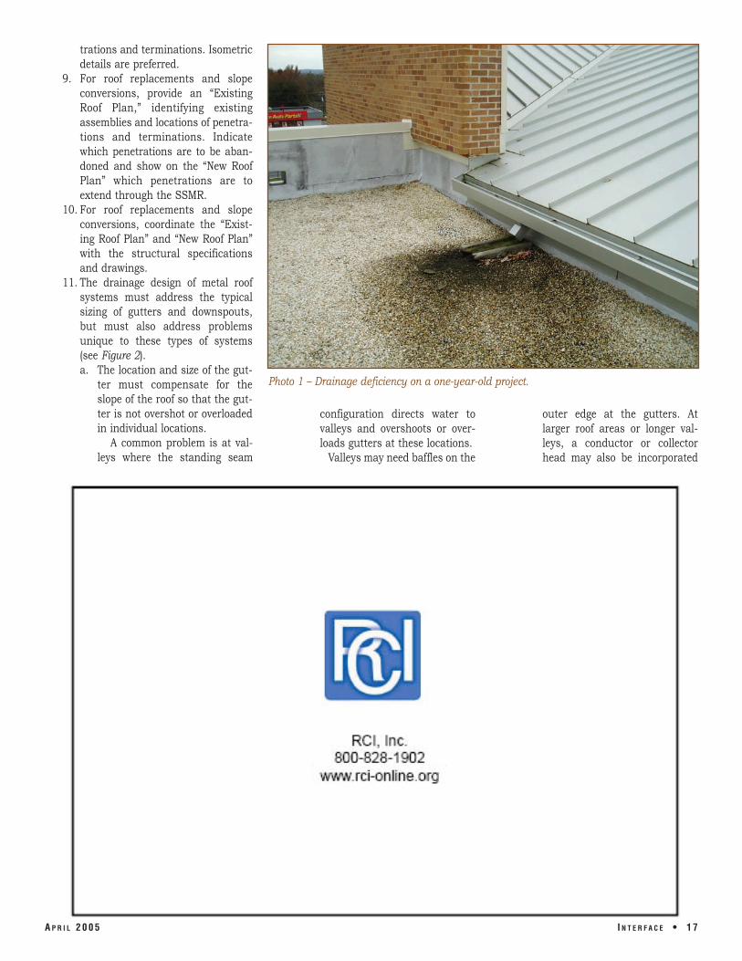
11. The drainage design of metal roof systems must address the typical sizing of gutters and downspouts, but must also address problems unique to these types of systems (see Figure 2). a. The location and size of the gut
ter must compensate for the slope of the roof so that the gutter is not overshot or overloaded in individual locations.
A common problem is at valleys where the standing seam
Photo 1 – Drainage deficiency on a one-year-old project.
configuration directs water to outer edge at the gutters. At valleys and overshoots or over- larger roof areas or longer valloads gutters at these locations. leys, a conductor or collector
Valleys may need baffles on the head may also be incorporated
A P R I L 2 0 0 5 I N T E R F A C E • 1 7
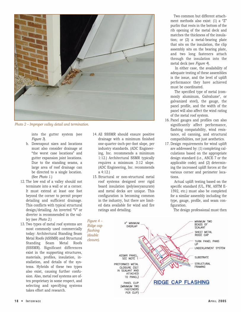
Photo 2 – Improper valley detail and termination.
into the gutter system (see Figure 3).
b. Downspout sizes and locations must also consider drainage at “the worst case locations” and gutter expansion joint locations. Due to the standing seams, a large area of roof drainage can be directed to a single location. (See Photo 1.)
12. The low end of a valley should not terminate into a wall or at a corner. It must extend at least one foot beyond the corner to permit proper detailing and sufficient drainage. This conflicts with typical structural design/detailing. An inverted “V” or diverter is recommended in the valley (see Photo 2.)
13. Two types of metal roof systems are most commonly used commercially today: Architectural Standing Seam Metal Roofs (ASSMR) and Structural Standing Seam Metal Roofs (SSSMR). Significant differences exist in the supporting structures, materials, profiles, insulation, installation, and details of the systems. Hybrids of these two types also exist, causing further confusion. Also, metal roof systems are often proprietary in some respect, and selecting and specifying systems takes effort and research.
14. All SSSMR should ensure positive drainage with a minimum finished one-quarter-inch-per-foot slope, per industry standards. (ADC Engineering, Inc. recommends a minimum 1:12.) Architectural SSMR typically requires a minimum 3:12 slope. (ADC Engineering, Inc. recommends a 4:12.)
15. Structural or non-structural metal roof systems designed over rigid board insulation (polyisocyanurate) and metal decks are unique. This configuration is becoming common in the industry, but there are limited data available for wind and fire ratings and detailing.
Figure 4 – Ridge cap flashing (double closure).
Two common but different attachment methods also exist: (1) a “Z” purlin that rests in the bottom of the rib opening of the metal deck and matches the thickness of the insulation; or (2) a metal-bearing plate that sits on the insulation, the clip assembly sits on the bearing plate, and two long fasteners attach through the insulation into the metal deck (see Figure 4).
In either case, the availability of adequate testing of these assemblies is the issue, and the level of uplift performance they have achieved must be coordinated.
The specified type of metal (commonly aluminum, Galvalume®, or galvanized steel), the gauge, the panel profile, and the width of the panel will also affect the wind rating of the metal roof system.
16. Panel gauges and profiles can also significantly affect performance, flashing compatability, wind resistance, oil canning, and structural compatibilities, not just aesthetics.
17. Design requirements for wind uplift are addressed by: (1) completing calculations based on the appropriate design standard (i.e., ASCE 7 or the applicable code); and (2) determining the increased uplift forces at the various corner and perimeter locations.
Actual uplift testing based on the specific standard (UL, FM, ASTM E1592, etc.) must also be completed for a similar assembly including the type, gauge, profile, and seam configuration.
The design professional must then
1 8 • I N T E R F A C E A P R I L 2 0 0 5
make a determination that the specific assembly can meet the specific uplift forces based on a clearly defined attachment method for the panel in the field, corner, and perimeter locations.
Although the design requirements and uplift testing provide limited information specific to flashing, appropriate requirements must be incorporated into the various termination details (i.e., eave, rake, hips, ridges, etc.) for these forces and must be shown in the design and submittal process.
18. All roof systems experience varying uplift forces at corners and perimeter. Ensure that the design and submittals clearly identify boundaries of the perimeter and corners and how the increased attachment occurs at these locations. Secondary framing is often in these locations. Also be aware of the restrictions on wind speeds with warranties for metal roof systems. Requirements for thermal calculations are needed to determine the anticipated movement and to allow this movement within the detailing of penetrations and terminations. a. The type of clip and its position
ing are critical to provide the ability for movement.
b. The state of expansion of the metal during application affects the installation and detailing.
c. The point of fixation varies in the industry. Some fix the panel at the eave, others fix the panel at the ridge, and on occasion it is fixed at a midpoint. This will affect the wind uplift resistance and detailing.
19. Additional or secondary steel framing are always a controversial issue. Numerous benefits are gained by providing these members around the perimeter of buildings and at various penetrations. In re-roofing applications, the existing structure often requires additional framing at perimeters. Do not recommend eliminating these members without proper research and coordination.
20. All ridge and hip closures should have redundancy within the detail. Panels should have end dams and a closure detail to provide long-term performance. This is a common
problem area, especially on lower slopes (see Figure 5).
21. Penetrations through roofs should consider the location of the standing seams and the width of the panel to ensure that the penetration occurs in the flat portion of the panel and that adequate drainage can occur around the penetration. As noted above, the size at the opening around the penetration must allow for thermal movement (see Photo 3).
22. Oi1 canning is not a uniformly defined term in the roofing industry,
and the level of acceptable oil canning is always a difficult problem to resolve in the field. Establishing a level of acceptance prior to construction based on a similar project or mock-up within the contract is an option to consider.
The type of metal, slope of the roof, color, width of panel, and panel configuration are design items that can have an effect on the degree of oil canning. Storage, placement, and installation methods can also have a significant effect, as can the coil
A P R I L 2 0 0 5 I N T E R F A C E • 2 1
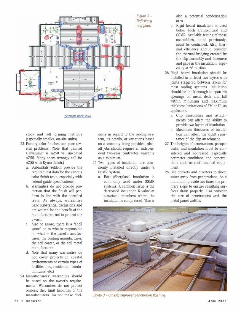
Photo 3 – Classic improper penetration flashing.
2 2 • I N T E R F A C E A P R I L 2 0 0 5
Figure 5 – Deficiency roof plan.
stock and roll forming methods (especially smaller, on-site units).
23. Factory color finishes can pose several problems: (Note that painted Galvalume® is AZ50 vs. uncoated AZ55. Many specs wrongly call for AZ55 with Kynar finish.) a. Submittals seldom provide the
required test data for the various color finish tests, especially with federal guide specifications.
b. Warranties do not provide protection that the finish will perform in line with the specified tests. As always, warranties have substantial exclusions and are written for the benefit of the manufacturer, not to protect the owner.
c. Also be aware, there is a “shell game” as to who is responsible for what — the panel manufacturer, the coating manufacturer, the coil coater, or the coil metal manufacturer.
d. Note that many warranties do not cover projects in coastal environments or certain types of facilities (i.e., residential, condominiums, etc.)
24. Manufacturers’ warranties should be based on the owner’s requirements. Warranties do not protect owners; they limit liabilities of the manufacturers. Do not make deci
sions in regard to the roofing system, its details, or variations based on a warranty being provided. Also, all jobs should require an independent two-year contractor warranty as a minimum.
25. Two types of insulation are commonly installed directly under a SSMR System. a. Batt (fiberglass) insulation is
commonly used under SSMR systems. A common issue is the decreased insulation R-value at structural members where the insulation is compressed. This is
also a potential condensation area.
b. Rigid board insulation is used below both architectural and SSMR. Available testing of these assemblies, noted previously, must be confirmed. Also, thermal efficiency should consider the thermal bridging created by the clip assembly and fasteners and gaps in the insulation, especially at “z” purlins.
26. Rigid board insulation should be installed in at least two layers with joints staggered between layers for most roofing systems. Insulation should be thick enough to span rib openings on metal deck and fall within minimum and maximum thickness limitations of FM or UL as applicable. a. Clip assemblies and attach
ments can affect the ability to provide two layers of insulation.
b. Maximum thickness of insulation can affect the uplift resistance of the clip attachment.
27. The heights of penetrations, parapet walls, and insulation must be considered and addressed, especially perimeter conditions and penetrations such as roof-mounted equipment.
28. Use crickets and diverters to direct water away from penetrations. As a minimum, provide two times the primary slope to ensure resulting surfaces drain properly. Also consider the size of penetrations and the metal panel widths.
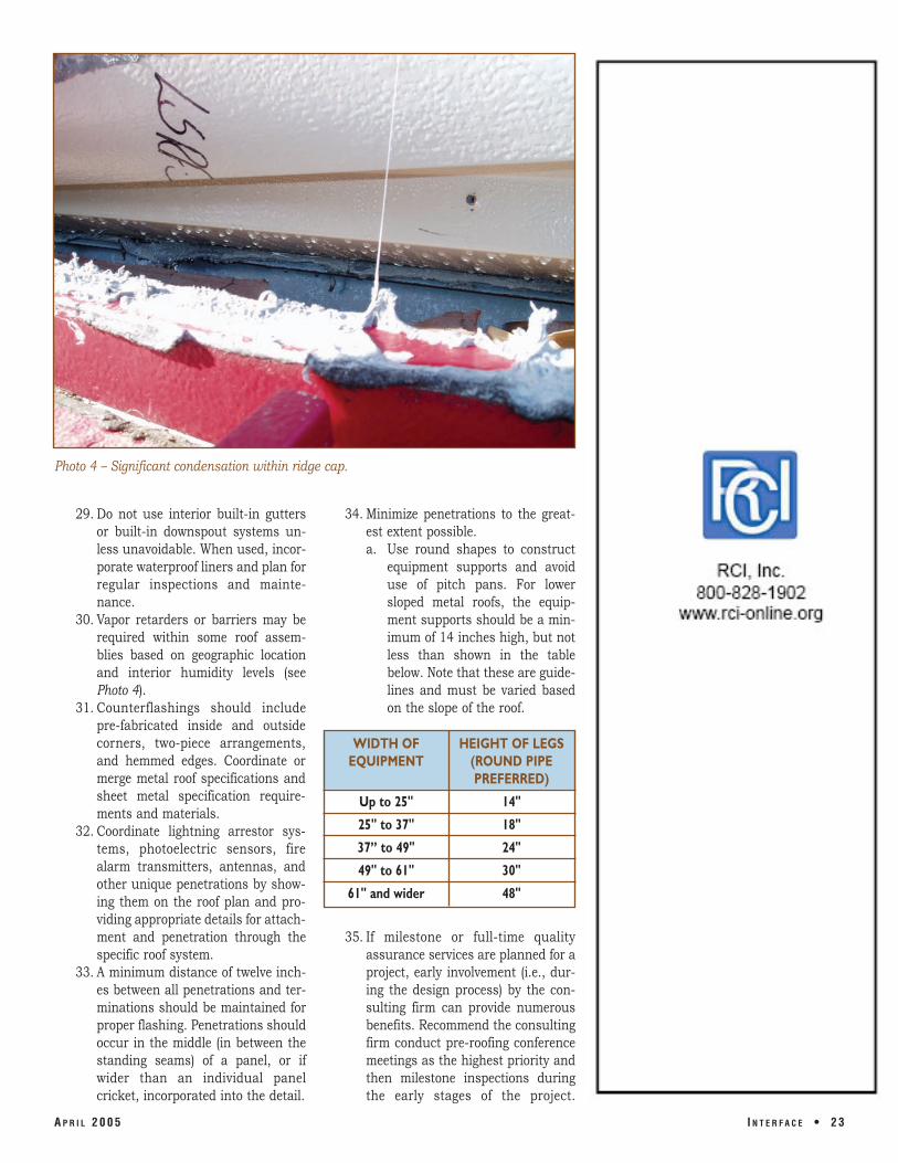
Photo 4 – Significant condensation within ridge cap.
29. Do not use interior built-in gutters or built-in downspout systems unless unavoidable. When used, incorporate waterproof liners and plan for regular inspections and maintenance.
30. Vapor retarders or barriers may be required within some roof assemblies based on geographic location and interior humidity levels (see Photo 4).
31. Counterflashings should include pre-fabricated inside and outside corners, two-piece arrangements, and hemmed edges. Coordinate or merge metal roof specifications and sheet metal specification requirements and materials.
32. Coordinate lightning arrestor systems, photoelectric sensors, fire alarm transmitters, antennas, and other unique penetrations by showing them on the roof plan and providing appropriate details for attachment and penetration through the specific roof system.
33. A minimum distance of twelve inches between all penetrations and terminations should be maintained for proper flashing. Penetrations should occur in the middle (in between the standing seams) of a panel, or if wider than an individual panel cricket, incorporated into the detail.
34. Minimize penetrations to the greatest extent possible. a. Use round shapes to construct
equipment supports and avoid use of pitch pans. For lower sloped metal roofs, the equipment supports should be a minimum of 14 inches high, but not less than shown in the table below. Note that these are guidelines and must be varied based on the slope of the roof.
WIDTH OF HEIGHT OF LEGS EQUIPMENT (ROUND PIPE
PREFERRED)
Up to 25" 14"
25" to 37" 18"
37” to 49" 24"
49" to 61" 30"
61" and wider 48"
35. If milestone or full-time quality assurance services are planned for a project, early involvement (i.e., during the design process) by the consulting firm can provide numerous benefits. Recommend the consulting firm conduct pre-roofing conference meetings as the highest priority and then milestone inspections during the early stages of the project.
A P R I L 2 0 0 5 I N T E R F A C E • 2 3
Inspections made after problems occur or at the end of the project focus on defining what can be accepted versus providing a quality roof system.
CONCLUSION The above checklist will bore some and
infuriate others, but hopefully it will provide some insight and information for most readers. It was not intended to answer all questions or to discuss all of the problems with standing seam metal roofs, but outline many of the common plights and shortcomings.
The viewpoint is intended to be generic and objective from a design professional perspective.
ADDITIONAL SOURCES OF INFORMATION 1. Architectural Sheet Metal Manual,
6th Edition, Sheet Metal & Air Conditioning National Association (SMACNA), 1993.
2. Manual for Inspection and Main- ers Association for the Metal Roofing tenance of Low-Sloped Structural Systems Industry, 2000. Metal Panel Roof Assemblies, Nat- 5. The NRCA Roofing and Waterproofing ional Roofing Contractors Associa- Manual, Fifth Edition, National tion, 2002. Roofing Contractors Association.
3. Newman, Alexander, Metal Building 6. Haddock, Rob, Metal Roofing From A Systems Design and Specifications, to Z. 1997.
4. Metal Roofing Systems Design (First Edition), Metal Building Manufactur-
Richard L. Cook Jr., RRC, RWC, RRO
Richard L. Cook Jr., RRC, RWC, RRO, is a principal of ADC Engineering Inc., Hanahan, SC. Rick has authored numerous papers on the subject of roofing systems and wind-related damages. He has presented several papers at national symposia and conferences, including the American Society of Civil Engineers, the Construction Specifications Institute, RCI, and the Federal Construction Committee in Washington, D.C. Cook has also presented dozens of papers at local and regional meetings and conferences related to roofing and waterproofing in the construction industry.
2 4 • I N T E R F A C E A P R I L 2 0 0 5