Embed Size (px)
Citation preview
Univers
ity of
Cap
e Tow
n
Infrastructure Sharing of 5G Mobile CoreNetworks on an SDN/NFV Platform
Joyce Bertha Mwangama
Supervisor:Neco Ventura
Department of Electrical EngineeringUniversity of Cape Town
Thesis presented for the Degree of DOCTOR OF PHILOSOPHY in the Department ofElectrical Engineering, in the Faculty of Engineering and the Built Environment, at the
University of Cape Town
October 3, 2017

The copyright of this thesis vests in the author. No quotation from it or information derived from it is to be published without full acknowledgement of the source. The thesis is to be used for private study or non-commercial research purposes only.
Published by the University of Cape Town (UCT) in terms of the non-exclusive license granted to UCT by the author.
Univers
ity of
Cap
e Tow
n

Declaration
I declare that this thesis is my own work. Where collaboration with other people has
taken place, or material generated by other researchers is included, the parties and/or
material are indicated in the acknowledgements or references as appropriate.
This work is being submitted for the Doctor of Philosophy Degree in Electrical
Engineering at the University of Cape Town. It has not been submitted to any other
university for any other degree or examination.
Signature:
Joyce Bertha Mwangama
Date: October 3, 2017
i
Signature removed

Acknowledgements
I would like to thank the following individuals for their help during the course of this
project.
My dear family; Adam Mwangama, Yusta Mwangama and Alinanine Mwangama, thank
you for always believing in me.
Mr Neco Ventura, for his supervision and guidance throughout the duration of this
project. The hard work that you have put into the Centre of Broadband Networks is
inspirational. The many students that have undergone your supervision are lucky to
have had such an insightful learning experience under your guidance. I am fortunate to
have had your mentorship as well.
Prof. Dr Thomas Magedanz from the Fraunhofer Fokus research institute and Technical
University of Berlin. Thank you for always giving insightful and revolutionary research
ideas. Thank you for the continued partnership between your group and ours.
Thank you to all of the past and present members of the Communications Research
Group.
Holiday Kadada, thank you best friend. Kefilwe Lebepe and Ropfiwa Sithubi, thank you
best mates.
And thank you to Akeem Otun, the one I love.
ii

Abstract
When looking towards the deployment of 5G network architectures, mobile network
operators will continue to face many challenges. The number of customers is approaching
maximum market penetration, the number of devices per customer is increasing, and the
number of non-human operated devices estimated to approach towards the tens of billions,
network operators have a formidable task ahead of them.
The proliferation of cloud computing techniques has created a multitude of
applications for network services deployments, and at the forefront is the adoption
of Software-Defined Networking (SDN) and Network Functions Virtualisation (NFV).
Mobile network operators (MNO) have the opportunity to leverage these technologies
so that they can enable the delivery of traditional networking functionality in cloud
environments. The benefit of this is reductions seen in the capital and operational
expenditures of network infrastructure. When going for NFV, how a Virtualised Network
Function (VNF) is designed, implemented, and placed over physical infrastructure can
play a vital role on the performance metrics achieved by the network function. Not
paying careful attention to this aspect could lead to the drastically reduced performance
of network functions thus defeating the purpose of going for virtualisation solutions.
The success of mobile network operators in the 5G arena will depend heavily on their
ability to shift from their old operational models and embrace new technologies, design
principles and innovation in both the business and technical aspects of the environment.
The primary goal of this thesis is to design, implement and evaluate the viability of data
centre and cloud network infrastructure sharing use case. More specifically, the core
question addressed by this thesis is how virtualisation of network functions in a shared
infrastructure environment can be achieved without adverse performance degradation.
5G should be operational with high penetration beyond the year 2020 with data
traffic rates increasing exponentially and the number of connected devices expected to
surpass tens of billions. Requirements for 5G mobile networks include higher flexibility,
iii

scalability, cost effectiveness and energy efficiency. Towards these goals, Software Defined
Networking (SDN) and Network Functions Virtualisation have been adopted in recent
proposals for future mobile networks architectures because they are considered critical
technologies for 5G. A Shared Infrastructure Management Framework was designed and
implemented for this purpose. This framework was further enhanced for performance
optimisation of network functions and underlying physical infrastructure.
The objective achieved was the identification of requirements for the design and
development of an experimental testbed for future 5G mobile networks. This testbed
deploys high performance virtualised network functions (VNFs) while catering for the
infrastructure sharing use case of multiple network operators. The management and
orchestration of the VNFs allow for automation, scalability, fault recovery, and security
to be evaluated. The testbed developed is readily re-creatable and based on open-source
software.
iv

Contents
Declaration i
Acknowledgements ii
Abstract iii
Table of Contents v
List of Figures xii
List of Tables xvii
List of Acronyms xix
1 Introduction 1
1.1 The Evolved Packet Core . . . . . . . . . . . . . . . . . . . . . . . . . . . 3
1.2 Role of SDN and NFV in 5G . . . . . . . . . . . . . . . . . . . . . . . . . 4
1.2.1 5G – EPC Interfacing Options . . . . . . . . . . . . . . . . . . . . 5
1.2.2 Network Function Virtualisation . . . . . . . . . . . . . . . . . . . 7
v

1.2.3 Software Defined Networking . . . . . . . . . . . . . . . . . . . . 8
1.3 New Operating Environment . . . . . . . . . . . . . . . . . . . . . . . . . 9
1.3.1 Infrastructure as a Service . . . . . . . . . . . . . . . . . . . . . . 9
1.3.2 Infrastructure Sharing . . . . . . . . . . . . . . . . . . . . . . . . 10
1.4 Motivation and Challenges . . . . . . . . . . . . . . . . . . . . . . . . . . 11
1.5 Thesis Objectives . . . . . . . . . . . . . . . . . . . . . . . . . . . . . . . 15
1.6 Thesis Scope and Limitations . . . . . . . . . . . . . . . . . . . . . . . . 16
1.7 Contributions . . . . . . . . . . . . . . . . . . . . . . . . . . . . . . . . . 17
1.8 Thesis Outline . . . . . . . . . . . . . . . . . . . . . . . . . . . . . . . . . 21
2 Standardisation Issues 23
2.1 3GPP EPC and Current Release 13 . . . . . . . . . . . . . . . . . . . . . 24
2.1.1 Functional Elements . . . . . . . . . . . . . . . . . . . . . . . . . 25
2.1.2 Operations . . . . . . . . . . . . . . . . . . . . . . . . . . . . . . . 27
2.1.3 Reference Points Definitions . . . . . . . . . . . . . . . . . . . . . 28
2.2 ETSI NFV . . . . . . . . . . . . . . . . . . . . . . . . . . . . . . . . . . . 29
2.2.1 Functional Elements . . . . . . . . . . . . . . . . . . . . . . . . . 30
2.2.2 Reference Points Definitions . . . . . . . . . . . . . . . . . . . . . 33
2.3 ONF SDN . . . . . . . . . . . . . . . . . . . . . . . . . . . . . . . . . . . 35
2.3.1 Functional Elements . . . . . . . . . . . . . . . . . . . . . . . . . 36
2.3.2 Protocol Definitions . . . . . . . . . . . . . . . . . . . . . . . . . . 38
vi

2.4 Architectural Alignment . . . . . . . . . . . . . . . . . . . . . . . . . . . 39
2.4.1 Commom Virtualised 5G Core Framework . . . . . . . . . . . . . 39
2.4.2 Discussion . . . . . . . . . . . . . . . . . . . . . . . . . . . . . . . 40
3 Literature Review 41
3.1 Vertical Coordination . . . . . . . . . . . . . . . . . . . . . . . . . . . . . 42
3.1.1 Northbound Considerations: Evolved Packet Core (EPC) -
Network Functions Virtualisation (NFV) integration . . . . . . . . 42
3.1.2 Southbound Considerations: NFV - SDN Integration . . . . . . . 44
3.1.3 NFV Middleware Bypass: EPC - SDN Integration . . . . . . . . . 46
3.2 Management and Operations Coordination . . . . . . . . . . . . . . . . . 49
3.2.1 Infrastructure Sharing: Mobile Network Operator Case . . . . . . 50
3.2.2 Resource Monitoring . . . . . . . . . . . . . . . . . . . . . . . . . 54
3.2.3 Performance Enhancements . . . . . . . . . . . . . . . . . . . . . 55
3.3 Discussion . . . . . . . . . . . . . . . . . . . . . . . . . . . . . . . . . . . 56
4 Shared Infrastructure Management Framework 58
4.1 System Design Considerations . . . . . . . . . . . . . . . . . . . . . . . . 59
4.1.1 Ease of Transition Towards 5G . . . . . . . . . . . . . . . . . . . 59
4.1.2 Reduction of Costs . . . . . . . . . . . . . . . . . . . . . . . . . . 59
4.1.3 MNO Internal Isolation . . . . . . . . . . . . . . . . . . . . . . . . 60
4.1.4 Infrastructure Sharing Models . . . . . . . . . . . . . . . . . . . . 61
vii

4.1.5 Standards and Industry Conformance . . . . . . . . . . . . . . . . 62
4.1.6 Optimised and Energy Efficient Operation . . . . . . . . . . . . . 62
4.2 Shared Infrastructure Management . . . . . . . . . . . . . . . . . . . . . 63
4.2.1 Flexibility and Manageability . . . . . . . . . . . . . . . . . . . . 63
4.2.2 Security . . . . . . . . . . . . . . . . . . . . . . . . . . . . . . . . 63
4.2.3 Scalability . . . . . . . . . . . . . . . . . . . . . . . . . . . . . . . 64
4.2.4 Stability . . . . . . . . . . . . . . . . . . . . . . . . . . . . . . . . 64
4.3 Solution Architecture . . . . . . . . . . . . . . . . . . . . . . . . . . . . . 64
4.3.1 Infrastructure Control Plane . . . . . . . . . . . . . . . . . . . . . 65
4.3.2 Network Elements . . . . . . . . . . . . . . . . . . . . . . . . . . 68
4.3.3 Compute Elements . . . . . . . . . . . . . . . . . . . . . . . . . . 71
4.3.4 Management and Orchestration of MNOs . . . . . . . . . . . . . . 73
4.3.5 Element Interaction . . . . . . . . . . . . . . . . . . . . . . . . . . 77
4.4 Discussions . . . . . . . . . . . . . . . . . . . . . . . . . . . . . . . . . . 80
4.4.1 ETSI NFV Compliance . . . . . . . . . . . . . . . . . . . . . . . . 81
4.4.2 Component System Development . . . . . . . . . . . . . . . . . . 82
5 Performance Enhanced Framework 84
5.1 Design Considerations . . . . . . . . . . . . . . . . . . . . . . . . . . . . 85
5.1.1 High Level Performance Considerations . . . . . . . . . . . . . . . 85
5.1.2 VNF Specific Considerations . . . . . . . . . . . . . . . . . . . . . 86
viii

5.2 Performance Enhancement . . . . . . . . . . . . . . . . . . . . . . . . . 87
5.3 Solution Architecture . . . . . . . . . . . . . . . . . . . . . . . . . . . . . 91
5.3.1 Bypass the Hypervisor . . . . . . . . . . . . . . . . . . . . . . . . 91
5.3.2 Accelerate Virtualised Network Resources . . . . . . . . . . . . . 96
5.3.3 User Space Virtual Switching . . . . . . . . . . . . . . . . . . . . 99
5.3.4 Kernel Space Virtual Switching . . . . . . . . . . . . . . . . . . . 104
5.3.5 Accelerate VNFs Automation and Orchestration . . . . . . . . . . 107
5.4 Discussion . . . . . . . . . . . . . . . . . . . . . . . . . . . . . . . . . . . 112
6 Implementation of an Evaluation Framework 113
6.1 Testbed Virtualisation Components . . . . . . . . . . . . . . . . . . . . . 114
6.1.1 Overview . . . . . . . . . . . . . . . . . . . . . . . . . . . . . . . 114
6.1.2 OpenStack . . . . . . . . . . . . . . . . . . . . . . . . . . . . . . . 116
6.1.3 OpenDaylight . . . . . . . . . . . . . . . . . . . . . . . . . . . . . 122
6.1.4 Virtual Networking . . . . . . . . . . . . . . . . . . . . . . . . . . 123
6.1.5 Hypervisor and Hypervisor bypass . . . . . . . . . . . . . . . . . 125
6.1.6 Monitoring . . . . . . . . . . . . . . . . . . . . . . . . . . . . . . 126
6.2 5G Emulation Tool . . . . . . . . . . . . . . . . . . . . . . . . . . . . . . 127
6.3 End User Equipment . . . . . . . . . . . . . . . . . . . . . . . . . . . . . 130
6.4 Summary . . . . . . . . . . . . . . . . . . . . . . . . . . . . . . . . . . . 131
ix

7 Performance Evaluation 133
7.1 Introduction . . . . . . . . . . . . . . . . . . . . . . . . . . . . . . . . . . 134
7.1.1 Evaluation Metrics . . . . . . . . . . . . . . . . . . . . . . . . . . 134
7.1.2 Evaluation Scenarios . . . . . . . . . . . . . . . . . . . . . . . . . 135
7.2 VNF Service Quality Metrics . . . . . . . . . . . . . . . . . . . . . . . . 136
7.2.1 VNF provision latencies . . . . . . . . . . . . . . . . . . . . . . . 137
7.2.2 VNF termination latencies . . . . . . . . . . . . . . . . . . . . . . 141
7.3 Virtual Network Slice Service Quality Metrics . . . . . . . . . . . . . . . 145
7.3.1 VN resources provision and termination latencies . . . . . . . . . 146
7.3.2 Network Slice Throughput Performance . . . . . . . . . . . . . . . 148
7.3.3 Network Slice Packet Loss . . . . . . . . . . . . . . . . . . . . . . 152
7.3.4 Network Slice Protocol Comparisons . . . . . . . . . . . . . . . . 154
7.4 Technology specific components quality metric . . . . . . . . . . . . . . . 155
7.5 Comparison with Other Solutions . . . . . . . . . . . . . . . . . . . . . . 160
7.6 Summary . . . . . . . . . . . . . . . . . . . . . . . . . . . . . . . . . . . 163
8 Conclusions and Recommendations 164
8.1 Conclusions . . . . . . . . . . . . . . . . . . . . . . . . . . . . . . . . . . 165
8.1.1 5G on the Horizon . . . . . . . . . . . . . . . . . . . . . . . . . . 165
8.1.2 Virtualised 5G Core Framework . . . . . . . . . . . . . . . . . . . 165
8.1.3 Management of Shared Infrastructure . . . . . . . . . . . . . . . . 166
x

8.1.4 Performance of Virtualised Functions . . . . . . . . . . . . . . . . 166
8.1.5 Open Source Testbed Implementation . . . . . . . . . . . . . . . . 167
8.1.6 Service Quality Measurements . . . . . . . . . . . . . . . . . . . . 167
8.2 Future Work . . . . . . . . . . . . . . . . . . . . . . . . . . . . . . . . . . 168
8.3 Core Network Function Split . . . . . . . . . . . . . . . . . . . . . . . . . 169
8.4 Unified Network Controller and Orchestrator . . . . . . . . . . . . . . . . 169
8.5 Container Isolated Multi-tenant VNFs . . . . . . . . . . . . . . . . . . . 169
8.6 Extended UE Scalability . . . . . . . . . . . . . . . . . . . . . . . . . . . 170
Bibliography 171
A Network Templates 184
A.1 Virtual Network Template . . . . . . . . . . . . . . . . . . . . . . . . . . 184
A.2 VNF Templates . . . . . . . . . . . . . . . . . . . . . . . . . . . . . . . . 187
B Evaluation Framework Hardware Specifications 195
xi

List of Figures
1.1 The EPC enables past, current and future network architectures. . . . . . 3
1.2 5G potential landscape and overview [8] . . . . . . . . . . . . . . . . . . 5
2.1 Basic EPC architecture with E-UTRAN access . . . . . . . . . . . . . . . 25
2.2 Evolved Packet System (EPS) Architecture . . . . . . . . . . . . . . . . . 28
2.3 NFV Reference Architectural Framework [39] . . . . . . . . . . . . . . . 31
2.4 High Level NFV Architecture . . . . . . . . . . . . . . . . . . . . . . . . 35
2.5 SDN Layering [12] . . . . . . . . . . . . . . . . . . . . . . . . . . . . . . 37
2.6 OpenFlow Switch Operations [12] . . . . . . . . . . . . . . . . . . . . . . 37
2.7 Architecture Alignment . . . . . . . . . . . . . . . . . . . . . . . . . . . . 39
4.1 The High-Level architecture for Shared Infrastructure Management
Framework . . . . . . . . . . . . . . . . . . . . . . . . . . . . . . . . . . . 65
4.2 Network Architecture . . . . . . . . . . . . . . . . . . . . . . . . . . . . . 69
4.3 Network Operator Model . . . . . . . . . . . . . . . . . . . . . . . . . . . 74
4.4 Network Element Interconnection . . . . . . . . . . . . . . . . . . . . . . 76
4.5 Underlay and Overlay Network Model . . . . . . . . . . . . . . . . . . . . 77
xii

4.6 The Signalling Flow for a VNF Launch Request . . . . . . . . . . . . . . 78
4.7 VNF Launch Request Parameters . . . . . . . . . . . . . . . . . . . . . . 79
4.8 VNF Status Attributes . . . . . . . . . . . . . . . . . . . . . . . . . . . . 80
4.9 Architectural Alignment . . . . . . . . . . . . . . . . . . . . . . . . . . . 81
5.1 NFV ETSI Acceleration Layers . . . . . . . . . . . . . . . . . . . . . . . 88
5.2 Modified NFVI Architecture . . . . . . . . . . . . . . . . . . . . . . . . . 91
5.3 Virtualisation Approaches . . . . . . . . . . . . . . . . . . . . . . . . . . 92
5.4 The Signalling Flow for a Bare Metal VNF Launch Request . . . . . . . 94
5.5 Data centre compute nodes model . . . . . . . . . . . . . . . . . . . . . . 95
5.6 The Interfaces and Components of Open vSwitch (OVS) [103] . . . . . . 97
5.7 Virtual Network Resources and Operating Spaces . . . . . . . . . . . . . 98
5.8 Compute Node Internal Virtual Network Components in User Space . . . 100
5.9 Integration bridge flow table . . . . . . . . . . . . . . . . . . . . . . . . . 102
5.10 OVS tunnel bridge flow table . . . . . . . . . . . . . . . . . . . . . . . . 104
5.11 Compute Node Internal Virtual Network Components in Kernel Space . . 105
5.12 Kernel Space Tunnelling Lookup via the Data Centre Network Controller 106
5.13 EPC Functions and Network Interconnections . . . . . . . . . . . . . . . 107
5.14 eNodeB VNF MANO template . . . . . . . . . . . . . . . . . . . . . . . 111
6.1 Testbed physical server architecture . . . . . . . . . . . . . . . . . . . . . 115
6.2 OpenStack Diagram [86] . . . . . . . . . . . . . . . . . . . . . . . . . . . 117
xiii

6.3 Administrator environment variables . . . . . . . . . . . . . . . . . . . . 118
6.4 Jupiter MVNO tenant environment variables . . . . . . . . . . . . . . . . 118
6.5 Horizon dashboard login interface . . . . . . . . . . . . . . . . . . . . . . 119
6.6 Horizon dashboard image repository . . . . . . . . . . . . . . . . . . . . . 120
6.7 OpenEPC component interconnection . . . . . . . . . . . . . . . . . . . . 128
6.8 OpenIMS component interaction . . . . . . . . . . . . . . . . . . . . . . . 129
6.9 The Fokus EPC mobility management entity GUI interface . . . . . . . . 130
6.10 Video on Demand application service on the EU . . . . . . . . . . . . . . 131
7.1 VM Lifecycle Management . . . . . . . . . . . . . . . . . . . . . . . . . . 136
7.2 VNF provision activity diagram. . . . . . . . . . . . . . . . . . . . . . . . 138
7.3 Enablers provisioning . . . . . . . . . . . . . . . . . . . . . . . . . . . . . 140
7.4 PGW provisioning . . . . . . . . . . . . . . . . . . . . . . . . . . . . . . 140
7.5 SGW provisioning . . . . . . . . . . . . . . . . . . . . . . . . . . . . . . . 140
7.6 eNodeB provisioning . . . . . . . . . . . . . . . . . . . . . . . . . . . . . 140
7.7 VNF termination activity diagrams . . . . . . . . . . . . . . . . . . . . . 142
7.8 Enablers termination . . . . . . . . . . . . . . . . . . . . . . . . . . . . . 144
7.9 PGW termination . . . . . . . . . . . . . . . . . . . . . . . . . . . . . . . 144
7.10 SGW termination . . . . . . . . . . . . . . . . . . . . . . . . . . . . . . . 144
7.11 eNodeB termination . . . . . . . . . . . . . . . . . . . . . . . . . . . . . 144
7.12 VN provision/termination activity diagrams . . . . . . . . . . . . . . . . 146
xiv

7.13 100 VN provision events . . . . . . . . . . . . . . . . . . . . . . . . . . . 147
7.14 100 VN termination results . . . . . . . . . . . . . . . . . . . . . . . . . . 147
7.15 Network slice makeup for the 3 scenarios . . . . . . . . . . . . . . . . . . 149
7.16 4 network slices regardless of the scenario . . . . . . . . . . . . . . . . . . 149
7.17 1 network slice: send stats . . . . . . . . . . . . . . . . . . . . . . . . . . 150
7.18 1 network slice recv stats . . . . . . . . . . . . . . . . . . . . . . . . . . . 150
7.19 2 network slices send stats . . . . . . . . . . . . . . . . . . . . . . . . . . 150
7.20 2 network slices: recv stats . . . . . . . . . . . . . . . . . . . . . . . . . . 150
7.21 3 network slices: send stats . . . . . . . . . . . . . . . . . . . . . . . . . . 150
7.22 3 network slices: recv stats . . . . . . . . . . . . . . . . . . . . . . . . . . 150
7.23 4 network slices: send stats . . . . . . . . . . . . . . . . . . . . . . . . . . 151
7.24 4 network slices: recv stats . . . . . . . . . . . . . . . . . . . . . . . . . . 151
7.25 1 slice: effective error rate . . . . . . . . . . . . . . . . . . . . . . . . . . 152
7.26 2 slices: effective error rate . . . . . . . . . . . . . . . . . . . . . . . . . . 152
7.27 3 slices: effective error rate . . . . . . . . . . . . . . . . . . . . . . . . . . 153
7.28 4 slices: effective error rate . . . . . . . . . . . . . . . . . . . . . . . . . . 153
7.29 Compute node CPU load . . . . . . . . . . . . . . . . . . . . . . . . . . . 154
7.30 Compute node memory utilisation . . . . . . . . . . . . . . . . . . . . . . 154
7.31 Throughput in TCP . . . . . . . . . . . . . . . . . . . . . . . . . . . . . 155
7.32 Throughput on constant packet size in TCP and UDP . . . . . . . . . . 155
xv

7.33 EPC generic attach procedure . . . . . . . . . . . . . . . . . . . . . . . . 157
7.34 Tenant vEPC and vIMS on Horizon . . . . . . . . . . . . . . . . . . . . . 157
7.35 EPC attach latency measurements . . . . . . . . . . . . . . . . . . . . . . 158
A.1 EPDG VNF MANO template . . . . . . . . . . . . . . . . . . . . . . . . 187
A.2 SGW VNF MANO template . . . . . . . . . . . . . . . . . . . . . . . . . 188
A.3 PGW VNF MANO template . . . . . . . . . . . . . . . . . . . . . . . . . 189
A.4 IMS VNF MANO template . . . . . . . . . . . . . . . . . . . . . . . . . 190
A.5 PCC VNF MANO template . . . . . . . . . . . . . . . . . . . . . . . . . 191
A.6 MTC-SERVER VNF MANO template . . . . . . . . . . . . . . . . . . . 192
A.7 MTC-Gateway VNF MANO template . . . . . . . . . . . . . . . . . . . . 193
A.8 CDN VNF MANO template . . . . . . . . . . . . . . . . . . . . . . . . . 194
xvi

List of Tables
4.1 VN elements [99] . . . . . . . . . . . . . . . . . . . . . . . . . . . . . . . 75
4.2 System developments . . . . . . . . . . . . . . . . . . . . . . . . . . . . . 83
5.1 Types of Accelerators . . . . . . . . . . . . . . . . . . . . . . . . . . . . . 89
5.2 Accelerator Location . . . . . . . . . . . . . . . . . . . . . . . . . . . . . 90
5.3 Accelerator Functionality Type . . . . . . . . . . . . . . . . . . . . . . . 90
5.4 EPC virtual networks . . . . . . . . . . . . . . . . . . . . . . . . . . . . . 109
6.1 Physical testbed networks . . . . . . . . . . . . . . . . . . . . . . . . . . 116
6.2 Virtual network architectures implemented . . . . . . . . . . . . . . . . . 122
7.1 VNF provision latency results for Enablers VNF . . . . . . . . . . . . . . 139
7.2 VNF provision latency results for PGW VNF . . . . . . . . . . . . . . . 139
7.3 VNF provision latency results for SGW VNF . . . . . . . . . . . . . . . . 139
7.4 VNF provision latency results for eNodeB VNF . . . . . . . . . . . . . . 140
7.5 VNF termination latency results for Enablers . . . . . . . . . . . . . . . 143
7.6 VNF termination latency results for PGW . . . . . . . . . . . . . . . . . 143
xvii

7.7 VNF termination latency results for SGW . . . . . . . . . . . . . . . . . 143
7.8 VNF termination latency results for eNodeB . . . . . . . . . . . . . . . . 144
7.9 VN provision latency results . . . . . . . . . . . . . . . . . . . . . . . . . 147
7.10 VN termination latency results . . . . . . . . . . . . . . . . . . . . . . . 148
7.11 Network attach latency results . . . . . . . . . . . . . . . . . . . . . . . . 158
7.12 Session initiation setup delays . . . . . . . . . . . . . . . . . . . . . . . . 158
7.13 GBR connection latency . . . . . . . . . . . . . . . . . . . . . . . . . . . 159
7.14 Packet delay variation . . . . . . . . . . . . . . . . . . . . . . . . . . . . 159
7.15 Packet loss ratio . . . . . . . . . . . . . . . . . . . . . . . . . . . . . . . . 159
7.16 Connection throughput . . . . . . . . . . . . . . . . . . . . . . . . . . . . 159
B.1 OpenStack Hardware Specifications . . . . . . . . . . . . . . . . . . . . . 195
B.2 Administration Hardware Specifications . . . . . . . . . . . . . . . . . . . 196
xviii
List of Acronyms
1G First Generation of Mobile Communications.
2.5G 2G Packet Data Improvement.
2G Second Generation of Mobile
Communications.
3G Third Generation of Mobile Communications.
3GPP Third Generation Partnership Project.
4G Fourth Generation of Mobile
Communications.
5G Fifth Generation of Mobile Communications.
AF Application Function.
ARP Address Resolution Protocol.
AuC Authentication Centre.
BBERF Bearer Binding and Event Report Function.
BSS Business Support System.
CAPEX Capital Expenditure.
CDMA2000 IMT-CDMA Multi-Carrier / Code-Division
Multiple Access 2000.
CDN Content Distribution Networks.
CN Compute Node.
CPU Central Processing Units.
CSCF Call Service Control Function.
DAAD German Academic Exchange Service.
DHCP Dynamic Host Configuration Protocol.
DNS Domain Name System.
DPDK Data Plane Development Kit.
DSCP DiffServ Code Points.
DVR Distributed Virtual Router.
E-UTRAN Evolved UTRAN.
xix

eBPF extended Berkeley Packet Filter.
EMS Element Management System.
eNodeB Evolved NodeB.
EPC Evolved Packet Core.
ePDG Evolved Packet Data Gateway.
EPS Evolved Packet System.
ETSI European Telecommunications Standards
Institute.
EU End User.
FOSS Free and Open Source Software.
GBR Guarenteed Bit Rate.
GDP Gross Domestic Product.
GENEVE Generic Network Virtulisation Encapsulation.
GERAN GSM EDGE Radio Access Network.
GPRS General Packet Radio Service.
GPU Graphical Processing Units.
GRE Generic Routing Encapsulation.
GSM Global System for Mobile Communications.
GTP GPRS Tunneling Protocol.
HD Hard Disk.
HLR Home Location Register.
HSPA High-Speed Packet Access.
HSS Home Subscriber Server.
HWA Hardware Acceleration.
I-CSCF Interrogating CSCF.
IaaS Infrastructure as a Service.
ICT Information and Communication
Technologies.
IMS IP Multimedia Core Network Subsystem.
IMT-2000 International Mobile Telecommunications -
2000.
IMT-Advanced International Mobile Telecommunications -
Advanced.
IOModule Input/Output Module.
IoT Internet of Things.
IP Internet Protocol.
IPsec Internet Protocol Security.
xx

ITU International Telecommunications Union.
KVM Kernel-based Virtual Machine.
LDC Least Developed Countries.
LTE Long Term Evolution.
M2M Machine to Machine.
MAC Media Access Control.
MANO Management and Orchestration.
MIMO Multiple Input Multiple Output.
MME Mobility Management Entity.
MNO Mobile Network Operator.
MTC Machine-Type Communication.
MVNO Mobile Virtual Network Operator.
NAS Network Attached Storage.
NAT Network Address Translation.
NFV Network Functions Virtualisation.
NFVI NFV Infrastructure.
NGMN Next Generation Mobile Networks Alliance.
NIC Network Interface Card.
NPU Network Processing Unit.
NTP Network Time Protocol.
ODL OpenDaylight.
ONF Open Networking Foundation.
OPEX Operational Expenditure.
OS Operating System.
OSS Operations Support System.
OTT Over The Top.
OVN Open Virtual Network.
OVS Open vSwitch.
OVSDB OVS Database.
P-CSCF Proxy CSCF.
PCC Policy and Charging Control.
PCEF Policy and Charging Enforcement Function.
PCRF Policy and Charging Rules Function.
PDN Packet Data Network.
PGW Packet Data Network Gateway.
PMIP Proxy Mobile IP.
PoP Point of Presence.
xxi
QCI QoS Class Identifiers.
Qcow2 QEMU Copy On Write version 2.
QoE Quality of Experience.
QoS Quality of Service.
RAM Random Access Memory.
RAN Radio Access Network.
RAT Radio Access Technology.
RTSP Real Time Streaming Protocol.
S-CSCF Serving CSCF.
SAE Systems Architecture Evolution.
SDN Software Defined Networks.
SDO Standards Development Organisation.
SDP Session Description Protocol.
SGW Serving Gateway.
SIMF Shared Infrastructure Management
Framework.
SIP Session Initiation Protocol.
SLA Service Level Agreement.
SPR Service Profile Repository.
SQL Structured Query Language.
SR-IOV Single-Root Input/Output Virtualisation.
TCP Transport Control Protocol.
TEID Tunnel Endpoint Identifier.
TLS Transport Layer Security.
TRESCIMO Testbeds for Reliable Smart City M2M
Communication.
UCT University of Cape Town.
UE User Equipment.
UMTS Universal Mobile Telecommunications
System.
UNIFI Universities for Future Internet.
UTRAN UMTS Terrestrial Radio Access Network.
vCPU Virtualised CPU.
vEPC Virtualised EPC.
VIM Virtualised Infrastructure Manager.
vIMS Virtualised IMS.
VLAN Virtual Local Area Network.
xxii

VM Virtual Machine.
VN Virtual Network.
VNF Virtualised Network Function.
VNO Virtual Network Operator.
VoD Video on Demand.
VoLTE Voice over LTE.
VTN Virtual Tenant Network.
VxLAN Virtual Extensible Local Area Network.
WCDMA Wideband Code Division Multiple Access.
WiMAX Worldwide Interoperability for Microwave
Access.
WLAN Wireless Local Area Network.
XDP eXpress Data Path.
xxiii

Chapter 1
Introduction
Mobile communications play a vital role in enabling the digital connectivity of 3.73 billion
users around the world [1]. The first significant deployments of mobile or cellular network
systems occurred around 1981-1983 [2]. The technology behind the First Generation of
Mobile Communications (1G) was based on analogue voice modulation. Introduced in
1991, the evolution of 1G or the Second Generation of Mobile Communications (2G)
was known as the Global System for Mobile Communications (GSM). The technology
behind its implementation was based on digital modulation techniques, which provided
significant gains in spectrum efficiency, and which in turn resulted in greater mobile
phone penetration [2]. Unlike 1G, 2G included additional to the voice telephony service
simple data and messaging service offerings. Up until this point the backhaul and core
networks domain that enabled mobile communications were based on circuit switching
technology. An improvement on 2G, known as 2G Packet Data Improvement (2.5G) or
General Packet Radio Service (GPRS), implemented a packet-switched domain to provide
faster data services, alongside the circuit-switched domain, which continued to support
voice services [2].
Planning for what would be known as the Third Generation of Mobile
Communications (3G) started in the 1980s and resulted in what was defined as
the International Mobile Telecommunications - 2000 (IMT-2000) technical standards
[3]. Different technologies were branded as 3G, for example, Universal Mobile
Telecommunications System (UMTS) in Europe and IMT-CDMA Multi-Carrier / Code-
Division Multiple Access 2000 (CDMA2000) in the United States. These technologies
were launched during the years of 1998 to 2000. The greatest improvement from the
1
CHAPTER 1. INTRODUCTION 2
previous generations was increased data rates, which inadvertently drove the popularity
of the mobile Internet. It was around this period that network operators started to
notice that the average revenue generated per subscriber per month was on the decline.
The period from 2005 – 2008 it had dropped by almost 15-20% [4]. Network operators
were finding themselves competing for end user attention as customers opted to make
use of cheaper or free Over The Top (OTT) services bypassing the network operator
who in the end was starting to look like a simple “bit-pipe”. To compensate for this,
network operators looked at deploying newer and enticing services. The 3G backhaul
and core network was thus starting to look very complex, as both packet-switched and
circuit-switched equipment was needed to support the network. This drove the need to
make 3G and beyond architectures more IP-centric to cater for the shifting trend of users
embracing data services. This also motivated the move towards a simplified and easier
to deploy network architecture.
The fourth and most recent generation of mobile communications networks,
Fourth Generation of Mobile Communications (4G) is defined by the International
Mobile Telecommunications - Advanced (IMT-Advanced) specifications [5]. While some
technologies are branded 4G such as Long Term Evolution (LTE), they do not strictly
comply with the specifications set out in IMT-Advanced. These “3.9G” technologies
were seen being deployed in 2011/2012 as a stopgap solution until “real” 4G technologies
were be ready [2]. One of the major objectives of 4G networks was to provide a flat,
simplified All-IP network architecture including support for voice services. This new
network design aims to achieve high-bandwidth availability for services and applications
of future mobile networks. It was designed to enable truly mobile broadband services
and applications and to ensure a smooth experience for both operators and end-users.
The Evolved Packet System (EPS), which comprises the LTE radio technology and the
Evolved Packet Core (EPC) network architecture, was the reference implementation for
mobile operators looking to deploy fourth generation and beyond mobile networks [6].
Thus, the survival of mobile network operators going forward lies in their ability to
leverage the need to increase network capacity, while handling the ever increasing, but
variable demand for network bandwidth. To meet this demand, operators need to invest
heavily in the Capital Expenditure (CAPEX) and Operational Expenditure (OPEX) of
their network infrastructure while at the same time implement streamlined efficient and
cost saving techniques in the deployment and maintenance of said infrastructure.
CHAPTER 1. INTRODUCTION 3
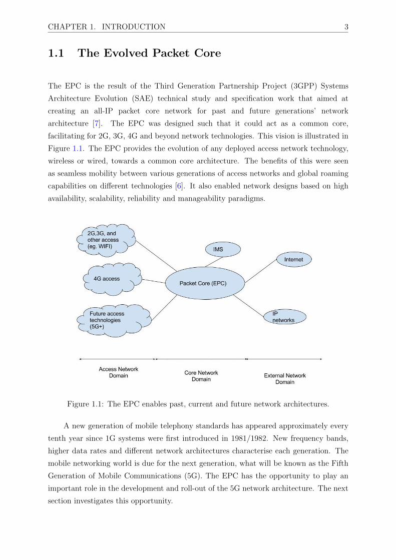
1.1 The Evolved Packet Core
The EPC is the result of the Third Generation Partnership Project (3GPP) Systems
Architecture Evolution (SAE) technical study and specification work that aimed at
creating an all-IP packet core network for past and future generations’ network
architecture [7]. The EPC was designed such that it could act as a common core,
facilitating for 2G, 3G, 4G and beyond network technologies. This vision is illustrated in
Figure 1.1. The EPC provides the evolution of any deployed access network technology,
wireless or wired, towards a common core architecture. The benefits of this were seen
as seamless mobility between various generations of access networks and global roaming
capabilities on different technologies [6]. It also enabled network designs based on high
availability, scalability, reliability and manageability paradigms.
Figure 1.1: The EPC enables past, current and future network architectures.
A new generation of mobile telephony standards has appeared approximately every
tenth year since 1G systems were first introduced in 1981/1982. New frequency bands,
higher data rates and different network architectures characterise each generation. The
mobile networking world is due for the next generation, what will be known as the Fifth
Generation of Mobile Communications (5G). The EPC has the opportunity to play an
important role in the development and roll-out of the 5G network architecture. The next
section investigates this opportunity.

CHAPTER 1. INTRODUCTION 4
1.2 Role of SDN and NFV in 5G
At the time of writing this thesis, there were no available standards on what 5G will
or should be. There is much speculation, however, and the Next Generation Mobile
Networks Alliance (NGMN) finalised its white paper in what is envisioned to be 5G. 5G
should be operational with high penetration beyond the year 2020. With data traffic
rates increasing exponentially and the number of connected devices expected to surpass
tens of billions, there are high expectations on 5G [8].
The design goals around 5G will be aimed at streamlining the performance and
efficiency of the network to achieve optimal network functionally and deployments. This
will result in achieving greater throughput while lowering network latencies; enabling
operations that are ultra-high reliable; higher connectivity densities; enhanced mobility
features; and an overall enhanced performance. While performance is pushed to the
extreme, efficiency is equally an important design aspect of 5G. The development of a
new and improved radio interface is an important objective of 5G. However, this will
not be the only improvement from 4G as an end-to-end system that streamlines the
functionalities of the entire network needs to be developed [8]. With Internet of Things
(IoT) expected to become widely popular, the 5G network will likely be the transport
enabler of the traffic generated by these services.
In fact, one cannot underplay the role that IoT will have on future networks. IoT has
emerged as the next big thing in the Future Internet. In the coming years, in the order
of tens of billions physical devices acting as sensors and actuators will have a connection
to the Internet [9]. These devices will generate massive amounts of traffic flows, some of
these data flows requiring real-time service characteristics. This wave of communications
requires the mobilisation and automation of industries, and industry processes in what is
called Machine-Type Communication (MTC) and IoT-enabled Industry 4.0 (the fourth
industrial revolution). Some of the services deployed in this landscape will be mission
critical. IoT will also have a wide range of requirements on networking such as reliability,
security, performance (latency, throughput), among others. The creation of new services
for vertical industries (e.g. health, automotive, home, energy) will not be limited to
connectivity but can require enablers from cloud computing, big data management,
security, logistics and other network-enabled capabilities [8].
The supporting 5G infrastructure will thus likely be developed around the ideas
of Software Defined Networks (SDN), NFV, big data produced from IoT and All-IP

CHAPTER 1. INTRODUCTION 5
principles as these allow for high flexibility, energy saving and cost efficiencies. As
such, the 5G architecture is a native SDN and NFV environment. 5G is expected to
cover aspects ranging from heterogeneous devices, mobile/fixed connectivity, physical and
virtual network functions and all the management and orchestration that will be required
in the 5G system. Operators can continue developing their own services, but can also
expand their business prospects by forming partnerships for both the infrastructure as
well as the application development aspects. This vision is illustrated in Figure 1.2.
Figure 1.2: 5G potential landscape and overview [8]
1.2.1 5G – EPC Interfacing Options
It is not yet known how the current network architecture will be designed or evolved to
support the 5G Radio Access Technology (RAT). The 5G RAT family could potentially
comprise multiple RATs optimised for different use cases. This could be a completely
new RAT, which is optimised to provide high data rates and capacity in higher frequency
bands, ultra-low latency and ultra-high reliability. Alongside or alternatively, the 5G
RAT could be based on an evolution of the LTE RAT technology, to provide coverage
and support for other use case categories such as low-end machine communications and
backwards compatibility for older devices.
Three interfacing options for the access technologies provide potential migration

CHAPTER 1. INTRODUCTION 6
paths towards 5G [8]. In the first interfacing option, all access-related components
supporting 5G are provided and interfaced through the legacy EPC, i.e. no new core
network design is specified. This option may require evolution of the EPC to ensure
that 5G access functions are interoperable. With this option, there is minimal impact to
legacy Radio Access Network (RAN) technologies. However, the drawback will be the
restriction of freedom to evolve the EPC in a manner that efficiently provides 5G access
functions to support the diversity of future use cases. Thus, the legacy paradigms would
be applied to all future use cases, which may be inefficient and expensive.
In the second option, the 5G access functions are provided both through an evolution
of the EPC and a new design for a future core network architecture. In this scenario, the
new core only supports the new RAT 5G while legacy and 4G are supported by the EPC.
The advantage of this option is that it allows the benefits of new technologies such as
virtualisation to be realised while at the same time minimising the impact to legacy access
technologies. However, the drawback is that the benefits of the new design can only be
realised in areas where there is 5G access coverage. Furthermore, due to limited coverage
of the new 5G access technology, interworking interfaces may be needed between the
new design to support mobility between 5G coverage and non-coverage areas. Providing
mobility support through such interfaces may cause significant signalling burdens.
In the final option, all components of the 5G RAT family are supported by the new
5G core network functions design. Older accesses, such as Wi-Fi and the fixed network,
may also be supported through the new design, but as a backup are supported through
the EPC to provide backwards compatibility for devices that cannot utilise the new design
(e.g. devices that only support up to a specific 3GPP Release version). Similar to the
second option, this allows the benefits of new technologies to be fully realised but now
even in areas where 5G coverage has not yet been achieved. In addition, it overcomes
the mobility issues associated with the second option. This is because mobility between
the new 5G RAT and 4G legacy can be handled by the same 5G core network functions
without the need for any interworking. Nevertheless, this option also introduces new
challenges. For instance, it requires the legacy and LTE RAN to be upgraded to support
both connection through the EPC and the new 5G core network design. Despite this,
option three is currently considered by NGMN as the preferred option as the access-
agnostic network functions should accommodate any new RATs, as well as LTE/LTE-
Advanced, Wi-Fi, and their evolution.
Regardless of the final architecture option, harmonising different identity and

CHAPTER 1. INTRODUCTION 7
authentication paradigms in cellular networks, (wireless) local access networks, and fixed
networks will be essential to enable the convergence of different access types, and also
to facilitate the realisation of different business models [8]. The architecture must also
facilitate further convergence of fixed and mobile networks in a manner that efficiently
addresses the needs and requirements originating from regulators. The EPC will play a
large role in facilitating for the 5G network.
1.2.2 Network Function Virtualisation
As 5G will encompass many technology pieces in the final integrated solution, NFV is
likely seen as playing a prominent role. The European Telecommunications Standards
Institute (ETSI) identified the importance of NFV in 2013. The initial documents
highlighted the benefits and challenges of NFV [10]. Network Functions Virtualisation is
the process of deploying standard network functions that were traditionally hardware
appliances, as software running over standard server hardware. The benefit is that
network functions can be instantiated as needed, migrated on demand, and scaled as
needed without the need of having to relocate any physical hardware. Data centres
would house the compute, storage and networking capabilities that the network operator
can exploit. NFV does away with the disadvantages of network operators having to
deploy proprietary hardware equipment. Capital investment is dramatically decreased;
operation costs are also reduced while deployment life cycles are shortened.
Operators’ networks are populated with a large and increasing variety of proprietary
hardware appliances. To launch a new network service often requires the addition
of updated versions of appliances and finding the space and power to accommodate
these boxes is becoming increasingly difficult. Compounded with the increasing energy
consumption of these appliances, the capital investments needed and the network
engineering skills needed to design, integrate and operate increasingly complex hardware-
based appliances, launching new network services is usually a complex task. Moreover,
hardware-based appliances rapidly reach end of life, requiring much of the procure-design-
integrate-deploy cycle to be repeated with little or no revenue benefit. Worse, hardware
lifecycles are becoming shorter as technology and services innovation accelerates rapidly,
inhibiting the roll out of new revenue generating network services and constraining
innovation in an increasingly network-centric connected world.
The Virtualised Network Function (VNF) could potentially offer many benefits. The

CHAPTER 1. INTRODUCTION 8
most obvious relates to reduced equipment costs and reduced power consumption through
consolidating equipment and exploiting the economies of scale of the IT industry [11].
Deploying VNFs could potentially increase the speed of time-to-market for new network
services by minimising the typical network operator cycle of innovation. Economies
of scale required to cover investments in hardware-based functionalities are no longer
applicable for software-based development. NFV would enable network operators to
significantly reduce the maturation cycle. VNFs will allow for the availability of
network appliance multi-version and multi-tenancy, which allows use of a single platform
for different applications, users and tenants. This allows network operators to share
resources across services and across different customer bases. NFV creates targeted
service introduction based on geography or customer sets. Services can be rapidly scaled
up/down as required. This enables a wide variety of eco-systems and encourages openness.
It opens the virtual appliance market to pure software entrants, small players and
academia, encouraging more innovation to bring new services and new revenue streams
quickly and at much lower risk.
1.2.3 Software Defined Networking
SDN is based around the concept of decoupling, in network forwarding equipment, the
system that makes decisions about where traffic is sent (the control plane) from the
underlying systems that forwards traffic to the selected destination (the data plane).
This process makes the network “programmable” as network control is centralised to a
remote server or controller that has an entire view of the network [12]. Abstracting the
control from the forwarding plane allows administrators to dynamically adjust network-
wide traffic flows to meet changing needs. SDN gives network managers the ability to
configure, manage, secure, and optimise network resources very quickly via dynamic,
automated SDN programs.
SDN abstracts control from forwarding which allows administrators to dynamically
adjust network-wide traffic flow to meet changing needs. In this new paradigm, the
network intelligence is centrally managed by an entity called the SDN controller. Through
the controller, network managers can configure, manage, secure and optimise network
resources adapting dynamically to changing network conditions. These automated SDN
programs can be written by them, or be based on proprietary software developers, however
unlike before there is no obligatory tie-in based on the vendor equipment chosen.

CHAPTER 1. INTRODUCTION 9
In fact, one of the main drivers behind the SDN movement was to champion open
standards-based and vendor-neutrality. When implemented utilising open standards,
SDN greatly simplifies network design and operation because instructions are provided
by SDN controllers instead of multiple proprietary protocols or vendor-specific devices.
In trying to meet the networking requirements posed by evolving computing trends,
network designers find themselves constrained by the limitations of current networks.
These include increasing network deployment and operational complexity; inability to
scale dynamically; vendor dependence and lack of interoperability.
While the ideas behind SDN and NFV seem similar, these two ideas are completely
separate and do not depend on each other, i.e. SDN can be deployed without NFV
and vice versa. There is a benefit, however, of marrying these two technologies as they
introduce a new operating environment with many possibilities.
1.3 New Operating Environment
Cloud computing, based on the techniques of SDN and NFV presents a unique use case
for mobile network operators, as they are now also able to benefit from the advantages of
deploying their services over these infrastructures. Apart from the radio advancements
required for future 5G mobile networks, efficiency and orchestration/management in the
core network, sees the concepts of NFV and SDN playing a major role in the deployment
of these networks [8].
1.3.1 Infrastructure as a Service
Infrastructure as a Service (IaaS) is a way of delivering cloud computing infrastructure
– servers, storage, networking and operating systems – as an on-demand service. Rather
than purchasing servers, software, data centre space or network equipment, clients instead
buy those resources as a fully outsourced services on demand.
In the IaaS paradigm, resources are distributed as a service. This allows for dynamic
scaling of the resources, introducing a variable cost, utility pricing model. IaaS also
generally includes multiple users on a single piece of hardware. IaaS makes sense in a
number of situations and these are closely related to the benefits that Cloud Computing

CHAPTER 1. INTRODUCTION 10
bring. Situations that are particularly suitable for Cloud infrastructure include where
demand is very volatile, where anytime there could be significant spikes and dips in
terms of demand on the infrastructure. IaaS is also advantageous for new organisations
that might lack sufficient capital to invest in hardware. It also benefits situations where
growing and rapidly scaling hardware is difficult or problematic. IaaS is built and
delivered using a set of technologies that start with virtualisation as the basic building
block. All the benefits obtainable from implementing IaaS seem to directly fit with the
network operators’ operational model.
1.3.2 Infrastructure Sharing
Bringing costs even further down is an important challenge mobile network operators will
be met with in the predicted increase in mobile traffic. To meet this demand, operators
will need to invest heavily in the CAPEX and OPEX of their network infrastructure. This
creates situations such that the full ownership model, where a single network operator
owns all of the infrastructure in their network, becomes too expensive to maintain. As a
natural consequence, a new business model has arisen, seeing network operators sharing
common network infrastructure to reduce expenditures.
Visiongain, a research organisation that provides analysis on worldwide telecoms
trends, concluded an extensive report on the aspect of network sharing for mobile network
operators [13]. In European mobile markets, up to 65 percent of network operators
were involved in some form of network sharing solutions. In addition, 60 percent of
network operators considered deploying network-sharing solutions when rolling out LTE
networks between 2010 and 2015. The report concluded on the benefits of achieving
network sharing among operators and identified the technical challenges involved in such
agreements.
While network-sharing solutions already existed, either as standardisation efforts
[14] or as vendor solutions, these had many drawbacks and did not fully address the
requirements of mobile network operators. These requirements included:
• extending the scope of sharing beyond just the radio access equipment
• increasing the isolation and separation of operators in both the data and control
plane

CHAPTER 1. INTRODUCTION 11
• privacy and security of operators and their users
• flexibility of accommodating operators with different services tailor-suited for their
customers
The goal would thus be to introduce an architecture for flexible and dynamic network
sharing among network operators. Current network sharing solutions have a sharing
scope restricted largely to the access network domain only. Current solutions also do not
cater for the need of isolation between the different business entities i.e. the network
operators. Isolation remains a big problem for network operators in such agreements.
This left operators vulnerable to having their private data, such as usage statistics and
customer information, open to scrutiny by other operators in the shared network.
While many network operators would not embrace network infrastructure sharing
with competitors, there are situations where a network operator is willing or even forced
to follow this route. These cases include:
• Governments of countries that make it compulsory for dominant network operators
to cooperate with smaller entities through the implementation of regulatory laws.
• Network operators that are new entrants to a market and do not have huge capital
to invest to adequately cover the market.
• Network operators that are looking to drastically streamline and optimise
operational costs looking at all ways to gain in energy and cost efficiency.
• Network operators that operate in markets where the incentive to have full
ownership of network equipment is not feasible and cooperation is the best option
for all players to pool together resources to be able to offer good services to the
customers, e.g. Least Developed Countries (LDC).
1.4 Motivation and Challenges
When looking towards the deployment of 5G network infrastructure mobile network
operators will continue to face a number of challenges. The number of customers is
said to increase, the number of devices per customer is increasing, and the number of

CHAPTER 1. INTRODUCTION 12
non-human operated devices estimated to approach towards the tens of billions, network
operators have a formidable task ahead of them. Coupled with the projected drastic
increase in mobile traffic volumes, the situation is complicated further. The Cisco Visual
Networking Index mobile forecast predicts that over a five-year period (2016 – 2021),
traffic will grow from 7.2 Exabytes per month to 49 Exabytes per month [15]. Network
operators are expected to cater for the exponentially increasing number of connections
into the network, they are also expected to provide higher bandwidths, lower latencies,
improved quality of service, 99.999% availability and uptime, and lastly offer all of this
at reduced costs to the customers while operating at a reasonable profit. The traditional
mobile network operator’s business model is not suited to this new environment, as it gets
more expensive to deploy and maintain new network equipment. Gone are the days when
network operators could profit offering simple services such as voice and text messaging
while making huge profits as was prevalent during the decades of 2G and 3G.
Cloud computing, based on the techniques of NFV and SDN, presents a unique
use case for mobile network operators, as they are now also able to benefit from the
advantages of deploying their services over these infrastructures. There is a large
complexity that can be expected from offering services in cloud environments. Mobile
network operators aim to provide wireless communication services to their customers
with very high availability [16]. Placing such a high burden on availability requirements,
operators would traditionally offer services using their own network infrastructures. In
the context of 5G mobile networks, this will become too expensive and income generation
will not be able to offset costs incurred. For this reason, cloud-computing techniques are
now seriously being considered in the mobile networking world as the next generation
of deployment option of networking functions. The task of virtualisation of commercial
mobile networks, deployed by network operators either on a regional or national scale,
requires a complex undertaking.
Challenge 1: Physical Infrastructure
Not surprisingly, the underlying hardware characteristics can have a deep impact on the
performance of network operations. For example, hardware dependant characteristics
such as the processor architecture, clock rate, size of the internal processor cache,
memory channels, memory speed, memory latency, bandwidth of inter-processor buses
or peripheral buses can have a strong impact on the performance of the VNF running
on that hardware. Multicore processor architectures, pipelining, multi-threading and
CHAPTER 1. INTRODUCTION 13
deadlock avoidance should be part of any VNF design, especially data plane VNFs
where performance is extremely important. The network function software should be
highly performant for a multitude of hardware architectures if the VNF is expected to
be hardware interoperable. Different deployment combinations of a VNF over a given
underlying hardware may result in drastically different performance depending on how the
VNF is mapped to hardware resources. Not paying careful attentions to these hardware
aspects could lead to drastically reduced performance of VNFs thus defeating the purpose
of going for virtualisation solutions for network operators.
Challenge 2: Virtualised Network Functions Performance
How a VNF is designed, implemented, and placed over physical infrastructure can play
a vital role on the performance metrics achieved by the function. Additionally, how
VNFs are interconnected is equally important. For example, VNF placement options rely
on the switching capabilities of the hypervisor, or alternatively bypass the hypervisor
or assume it does not exist while relying on advanced Network Interface Card (NIC)
capabilities (e.g. Single-Root Input/Output Virtualisation (SR-IOV)1). In the first case
a VNF is abstracted by the hypervisor, whereas in the second case, minimal abstraction is
provided and the VNF is operating as close to the bare metal as possible. Each technique
has its own advantages in terms of flexibility, isolation and performance. For instance,
virtual interfaces offered by hypervisors provide lower performance in comparison to
virtual interfaces offered over bare metal hardware aided by SR-IOV-compliant NICs.
Hypervisors’ virtual interfaces are much simpler to configure and might support VNF live
migration in a more natural way. The best option depends on the requirements of the
VNF and the nature of the involved workloads (for example data plane vs control plane or
network intensive vs compute intensive VNFs). The way that a VNF is designed should
take into consideration the physical environment where it will be deployed, and this will
inherently place a limitation on how the VNF can realistically achieve the performance
of a non-virtualised network function performing its similar function.
1In network virtualisation, SR-IOV is a network interface that allows the isolation of resources forperformance reasons. The SR-IOV allows different virtual machines to share a single PCI Expressinterface more efficiently without the assistance of a hypervisor to manage the resource sharing.

CHAPTER 1. INTRODUCTION 14
Challenge 3: Virtualisation Brings Portability at the Cost of
Performance
As mentioned above, there are different ways to run network functions as software-based
network functions. Deploying network functions directly on bare metal guarantees a
predictable performance since, in principle, the hardware mapping should be predictable
as hardware is directly allocated to VNFs’ virtual resources . However, resource isolation
is complex since different appliances will run as processes under the same Operating
System (OS) and it may be difficult to restrict visibility between software modules under
the same OS, thus failing to provide isolation if it is needed. Another restriction could
be that some appliances might have been designed to run on specific OSes or kernels
therefore only the same type can be supported by a specific bare metal instantiation.
Virtualisation through a hypervisor allows for VNF portability. This also allows
appliances to be run on the specific OS for which they were designed and not be restricted
to the underlying host OS. Furthermore, it provides a natural resource isolation (in terms
of visibility), from other VNFs that might belong to other tenants. The hypervisor layer
provides a guaranteed separation through a very strict mapping of hardware resources to
software modules of the VNFs. In general, the use of a hypervisor layer may add some
uncertainty to the performance as long as the VNF does not control the exact mapping
from the virtualised resource to the real hardware. An example is that some hypervisors
over-advertise resources in the hope that demand requested from VNFs remains low. The
worst case results in oversubscription of available resources where each VNF experiences
performance degradation as they have to share resources (e.g. memory, block storage,
virtual Central Processing Units (CPU) etc.).
Challenge 4: Virtualisation Introduces Complexity in
Management and Orchestration
VNFs should be deployed as simply as possible. In order to make this feasible, both VNFs
and the underlying hardware should be described through some kind of abstraction (e.g.
templates) this allows the automated matching by the orchestration and management
system. The definition and agreement of the final abstract descriptions is a challenge
being solved by Standards Development Organisations (SDOs) to ensure predictable
performance and portability in a manageable and automated environment.

CHAPTER 1. INTRODUCTION 15
Challenge 5: Infrastructure Sharing Complicates the
Virtualisation Use Case
Given the current worldwide trend towards 5G mobile operator networks, network sharing
is a potential solution to reduce capital and operational expenditure, especially in LDC
countries. Based on the financial restrictions that arise in this context, we further assume
that in particular the virtualisation of network functions is of interest for more intensive
cost reductions. By sharing NFV infrastructure between independent operators, further
cost savings could be facilitated.
A large amount of private and public research projects have been dedicated to
investigate future network technologies. Some have investigated the incorporation of SDN
and/or NFV in LTE-EPC mobile networks. Others further investigate the requirements
of the network-sharing scenario. A few perform a performance evaluation, comparing
for example to regular implementation non-SDN/virtualised networks, to identify the
feasibility, benefits and/or drawbacks in a practical deployment scenario.
1.5 Thesis Objectives
The success of network operators in the 5G arena will depend heavily on their ability to
shift from their old operational models, and embrace new technologies, design principles
and innovation in both the business and technical aspects of the environment. A
comprehensive review of both these business and technical aspects is needed to facilitate
a clear roadmap for what is needed.
This thesis has several objectives. First, it will carry out a comprehensive review
of the existing standardisation of the current generation of mobile network architecture
4G as well as what is expected by the SDOs to encompass 5G. This arena experiences
rapid developments and the literature review is a snapshot of current state of the art at
the time of writing the thesis, although it was developed and ongoing throughout the
duration of the project. This review will define the terms and elements used through the
remainder of this thesis.
Second, it is important to identify and address the key requirements of the
deployment of support and management equipment for future 5G networks. We already

CHAPTER 1. INTRODUCTION 16
highlight that the aspects of NFV, SDN, IaaS and infrastructure sharing will play a
vital role. This will involve addressing the challenges that are present in moving towards
deploying carrier grade mobile network services in uncertain and unpredictable virtualised
environments.
Third, it is imperative to define the mechanisms that allow for the deployment of
core network equipment in the defined landscape. This means identifying and catering
for the deployment of VNFs in 5G, identifying and incorporating the techniques of SDN
in the landscape, and for our case of infrastructure sharing develop a mechanism where
multiple operators can achieve this cooperatively and to the benefit of all involved. All
the while, the aim is to not lose in the performance that can be achieved from VNFs by
identifying strategies that can help to mitigate this.
Last, the primary objective of this thesis is to design, implement and evaluate the
viability of data centre and backbone network infrastructure sharing use case for network
operators looking to deploy 5G mobile core networks. More specifically, we identify
the requirements for the design and development of an experimental testbed for future
5G mobile networks; achieving high performance virtualised network functions VNFs;
catering for the infrastructure sharing use case; managing and orchestrating the VNFs
catering for automation, scalability, recovering from failures, and security; implement a
solution that is easily re-creatable and based on open-source software.
1.6 Thesis Scope and Limitations
While this work aims to prepare the scene for deployment of network functions in a 5G
environment, no such technology exists or has been defined. 4G is currently gaining
widespread deployment and LTE-Advanced technologies are continuing to evolve. As 5G
encompasses more than just the wireless technology, encapsulating NFV and SDN, these
technologies can be pursued for further investigation and deployment without having the
5G wireless technology present or defined. This work is then limited to the core network
area of 5G, i.e. independent of the radio access network technology, in the core network
of the mobile network, more specifically in the EPC.
As such, the focus of this work is the deployment of network functions as virtualised
resources over standard hardware. An important of aspect of NFV is the Management

CHAPTER 1. INTRODUCTION 17
and Orchestration (MANO) of VNFs as this impacts greatly in overall performance of
the VNFs. This work makes use of other tools that can achieve this, while focusing
on the aspect of network sharing of multiple network operators over shared physical
infrastructure. In the context of this work, the network-sharing scenario could entail
either multiple network operators working as equal partners, or one partner in an
infrastructure ownership position leasing resources to other partners.
The research scope is limited to the deployment of VNFs in a data centre. Moreover,
for this reason, the relevant performance metrics that will apply impact on the end user
consuming services delivered by VNF instances hosted on NFV Infrastructure (NFVI).
These metrics can be both those that affect the quality of service, such as IP packet loss
or end to end latency, and indirect effects such as failure to receive requested services due
to a failure in the NFVI management and orchestration domain.
While the solution is “SDN-friendly”, it is not strictly SDN implementation
optimised. The deployment tools chosen do cater for deeper integration of SDN if further
extensions are incorporated. This can be investigated further in future work. Lastly, while
the deployment makes use of reasonable hardware resources, certain practical limitations
may have hindered the ability to achieve optimal performance. If future work allows for
testing over more advanced facilities, it will be advantageous in answering some of the
questions left unanswered by this work.
1.7 Contributions
The major contributions of this thesis include:
• The critical review of the most prominent standardisation work in the areas related
to the future mobile networking architecture 5G, SDN, NFV and MANO. Secondly
a review of the state of the art in existing research and industrial related works /
implementation literature.
• Participate and lead in the activity of establishing the Universities for Future
Internet (UNIFI) data centre lab testbed at the University Cape Town. The
DAAD funded UNIFI project aimed to establish open and sustainable ICT
Experimentation and Research facilities enabling collaborative research and
developments in Future Internet research activities. This project was aimed partly

CHAPTER 1. INTRODUCTION 18
at investigating cloud computing based on NFV and SDN for mobile network
operators deploying 5G.
• Participated in the activity of establishing Testbeds for Reliable Smart City
M2M Communication (TRESCIMO) data centre lab testbed at the University
of Cape Town. TRESCIMO was funded from the European Union’s Seventh
Framework Programme (FP7/2007-2013), as well as the South African Department
of Science and Technology. The TRESCIMO testbed is based on a virtualised
standardised IoT middleware platform and an open-source framework for managing
and federating testbeds. The testbed consists of three interconnected sites located
in Berlin-Germany, Cape Town-South Africa and Pretoria-South Africa.
• Design, implementation and evaluation of NFV and SDN framework to facilitate
the deployment of network deployments that utilise these technologies. Design,
implementation and evaluation of the infrastructure sharing case where multiple
network operators are able to deploy and manage their networks over shared
infrastructure. A novel management framework that deals with the unique
requirements of this environment is developed and implemented. The direct results
of the research can be seen published in [17], [18], [19], [20] and [21].
These contributions are documented in the following peer review publications.
Publications:
1. Joyce Mwangama, Neco Ventura, ”Accelerated Virtual Switching Support of 5G
NFV-based Mobile Networks”, The 28th Annual IEEE International Symposium on
Personal, Indoor and Mobile Radio Communications (IEEE PIMRC 2017), October
2017. [17]
2. Joyce Mwangama, Ahmed M. Medhat, Thomas Magedanz, Neco Ventura,
”Performance Improvement of EPC Virtualised Network Functions Utilising
Bare Metal Provisioning” Southern African Telecommunications Networks and
Applications Conference (SATNAC 2017), Freedom of the Seas Cruise Liner
operated by Royal Caribbean International, Spain, September 2017 [18] .
3. Ahmed M. Medhat, Joyce Mwangama, Thomas Magedanz, Neco Ventura, ”QoS-
aware Delivery of VoIP Service through Dynamic Service Function Chaining in
5G Networks” Southern African Telecommunications Networks and Applications

CHAPTER 1. INTRODUCTION 19
Conference (SATNAC 2017), Freedom of the Seas Cruise Liner operated by Royal
Caribbean International, Spain, September 2017 [22].
4. Nyasha Mukudu, Joyce Mwangama, Neco Ventura, et. al, ”TRESCIMO:
Towards Software-Defined based Federated Internet of Things Testbeds across
Europe and South Africa to Enable FIRE Smart City Experimentation”, in FIRE
Book River Publishers [23].
5. Retselisitsoe Lejaha, Joyce Mwangama, ”SDN Based Security Solution for Multi-
Tenancy NFV” Southern African Telecommunications Networks and Applications
Conference (SATNAC 2016), George, Western Cape, South Africa, September 2016
[24].
6. Nyasha Mukudu, Neco Ventura, Joyce Mwangama, Asma Elmangoush, Thomas
Magedanz, “Prototyping Smart City Applications over Large Scale M2M Testbed”
IEEE IST-Africa 2016 Conference 11 – 13 May 2016, Durban, South Africa [25].
7. Louis Coetzee et al., ”TRESCIMO: European Union and South African Smart City
contextual dimensions,” Internet of Things (WF-IoT), 2015 IEEE 2nd World Forum
on, Milan, 2015, pp. 770-776 [26].
8. Ahmed M. Medhat, Thomas Magedanz, Joyce Mwangama, Neco Ventura,
“Virtualized Multi-Tenant EPC Networks” IEEE Workshop on Management Issues
in SDN, SDI and NFV collocated with 1st IEEE International Conference on
Network Softwarization (NetSoft 2015), London UK, 2015 [19].
9. Keagan Jarvis, Neco Ventura, Joyce Mwangama “Cloud based EPC: A Design
Approach” Southern African Telecommunications Networks and Applications
Conference (SATNAC 2015), Hermanus, Western Cape, South Africa, September
2015 [27].
10. Joyce Mwangama, Neco Ventura, Alexander Willner, Yahya Al-Hazmi,
Giuseppe Carella, Thomas Magedanz, “Towards Mobile Federated Network
Operators: Sharing Virtualized Network Functions in Low-Income Countries” IEEE
International Workshop on Software Defined 5G Networks (Soft5G 2015) collocated
with 1st IEEE International Conference on Network Softwarization (NetSoft 2015),
London UK, 2015 [20].
11. Joyce Mwangama, Neco Ventura, Ahmed M. Medhat “Investigating the
Deployment of 5G Mobile Core Networks in an Experimental Cloud Computing
Infrastructure” to appear in Southern African Telecommunications Networks and

CHAPTER 1. INTRODUCTION 20
Applications Conference (SATNAC 2015), Hermanus, Western Cape, South Africa,
September 2015 [21] (Selected as 2nd Best Paper of the Conference).
12. Andreea Ancuta Corici, Asma Elmangoush, Thomas Magedanz, Ronald Steinke,
Joyce Mwangama, Neco Ventura, “An OpenMTC platform-based interconnected
European–South African M2M Testbed for Smart City Services” 1st International
Conference on the use of Mobile Information and Communication Technology (ICT)
in Africa (UMICTA 2014), STIAS Conference Centre, Stellenbosch, South Africa,
2014 [28]
13. Joyce Mwangama, Joseph Orimolade, Neco Ventura, Asma Elmangoush,
Ronald Steinke, Alexander Willner, Andreea Corici and Thomas Magedanz.
”Prototyping Machine-to-Machine Applications for Emerging Smart Cities in
Developing Countries.” in Southern African n Telecommunication Networks and
Applications Conference (SATNAC 2014), Port Elizabeth, South Africa, September
2014 [29].
14. Joyce Mwangama and Neco Ventura, “Implementation of EPC Mobile Networks
using NFV and SDN” Southern African Telecommunication Networks and
Applications Conference (SATNAC 2014), Port Elizabeth, South Africa, September
2014 [30].
15. Andreea Corici, Asma Elmangoush, Ronald Steinke, Thomas Magedanz, Joyce
Mwangama, Neco Ventura. “Utilizing M2M technologies for Building Reliable
Smart Cities” First International Workshop on Architectures and Technologies for
Smart Cities, March 30th, 2014, Dubai, UAE [31]
16. Joyce Mwangama, Alexander Willner, Neco Ventura, Asma Elmangosh, Tom
Pfeifer, Thomas Magedanz. “Testbeds for Reliable Smart City Machine-to-Machine
Communication” Proceedings in Southern African Telecommunication Networks
and Applications Conference (SATNAC 2013), Stellenbosch, South Africa, 2013
[32].
17. Joyce Mwangama, Richard Spiers, Neco Ventura, Thomas Magedanz. “Past and
Current IMS Testbed Initiatives: The UCT IMS and EPC Testbed” Proceedings
in IEEE GLOBECOM Workshop on Open NGN and IMS Testbeds (ONIT 2012)
IEEE GLOBECOM Anaheim, California USA, December 2012 [33].
18. Joyce Mwangama, Neco Ventura. “Resource Management and Network Context
Awareness for IPTV Services in the 3GPP Evolved Packet Core” Proceedings in

CHAPTER 1. INTRODUCTION 21
the Southern African Telecommunication Networks and Applications Conference
(SATNAC 2012), George, South Africa, September 2012 [34].
1.8 Thesis Outline
Chapter 2 provides an extensive review of the ongoing standardisation regarding 5G
core networks, NFV, SDN, and NFV MANO. Of importance is the work done by the
SDOs; 3GPP EPC, Open Networking Foundation (ONF) SDN, ETSI NFV and MANO.
The chapter presents a snapshot of the state of art of current standards but these are
continually updated and added to at a rather fast pace.
A comprehensive literature review is presented in Chapter 3, examining the strides
made in research, academic and industry solutions and deployments in the three vertical
spaces (mobile core network, SDN and NFV/MANO). More focus is made on work that
encompassed more than one domain.
Chapter 4 presents the design and specification requirements for a Shared
Infrastructure Management Framework (SIMF). This framework proposes extensions to
the current NFV architecture to be able to accommodate the deployment of network
functions accommodating multiple network operators. The architecture is described in
detail regarding functional elements and extended interactions.
Chapter 5 presents the design and specifications requirements for a Performance
Enhanced SIMF. The chapter details the factors that greatly affect the performance
of different categories of VNFs of a Mobile Network Operator (MNO) and proposes a
placement framework to achieve high performance for 5G VNFs deployed in multi-tenant
data centres.
Chapter 6 presents the testbed implementation of a standards compliant NFV
framework. The testbed is described and implemented to showcase the integration of the
extensions needed for secure multi-tenancy as well as for improved performance of the
VNFs.
In Chapter 7 the described testbed and proposed enhancements are subjected to
validation and performance tests and results are presented. The evaluations demonstrate
proof of concept and also the effectiveness of the proposed enhancements.

CHAPTER 1. INTRODUCTION 22
Chapter 8 presents the conclusions drawn from the thesis and summarises the
contribution. Recommendations are made for areas of further study.
Chapter 2
Standardisation Issues
The idea of utilising SDN, NFV, the cloud and data centre technologies for the network
operators use case is a research area that is enjoying substantial attention in the past
few years. There are a number of SDOs working on various aspects, and in the
practical deployments this type of work enjoys many prototype implementations and
test usage scenarios. The dominant SDO’s operating in this space are the European
Telecommunications Standards Institute (ETSI) NFV [10], Open Networking Foundation
(ONF) SDN [12], Next Generation Mobile Networks Alliance (NGMN) 5G [8], and
Third Generation Partnership Project (3GPP) [35]. This chapter aims to provide a
comprehensive snapshot of the state of the art regarding these topics.
As the main aim of this study is to deploy EPC network functions, it is important
to understand the different functions, their interconnections and standardised operation.
3GPP being the main player in network function standardisation is the focus of our
review. The second aim of this study being to deploy network functions as software
only elements or virtualised network functions, the review of ETSI NFV’s work in this
area is particularly important. ETSI NFV has generated comprehensive documents
detailing requirements, definitions and case studies for the network function virtualisation
framework that they have developed. Towards the end of this chapter we highlight some
of the gaps within this framework in accomplishing the main goal of this thesis which
is infrastructure sharing. In terms of cloud computing, the main resources are identified
as computing, storage and networking. The network functions that we intend to deploy
are largely based on network intensive operations and the performance on computing is
less impacting on performance, even less for the storage case. For this reason, as well
23

CHAPTER 2. STANDARDISATION ISSUES 24
as many of the other benefits that SDN brings, we look at the prevalent standardisation
work being done in this area. Network functions that are optimised for SDN can be
expected to outperform those which are not.
Omitted from this study at this point is standardisation work done on network
sharing of network functions. This work is greatly outdated and most of the standards
that focus on this were developed during the time when network functions were not yet
being considered to be deployed as virtualised or software only technology components.
This chapter concludes by presenting an architectural framework that puts together all
of the important pieces from these three standardisation frameworks. We also highlight
the areas that additions should be made when considering for the network sharing use
case, which is one of the main focuses of our research.
2.1 3GPP EPC and Current Release 13
The Systems Architecture Evolution (SAE) was the name given for the work item on
the EPS, which was the technology specification for the 4G mobile broadband network
architecture [36]. The EPS comprised the LTE and EPC as the access network and
operator core network architectures respectively [35]. The EPC aimed at being the
“common core” support infrastructure for various radio access technologies (e.g. LTE,
legacy RANs, fixed accesses and non-3GPP wireless access). EPC is also the support
infrastructure for what is known as “LTE Evolution” or LTE-Advanced/LTE-Advanced
Pro.
3GPP has completed its work to be included in release 13 of the technical
specifications in 2016. The next release, release 14, is set to cover the requirements and
description of the 5G network. Of particular interest is the study on the management of
virtualised functions and the separation of control and data plane in the EPC network
functions to support some of the prevailing paradigms of current times.
It is important to understand the network functions that will be deployed as
virtualised elements of the author’s solution framework. While the functional entities
are standardised, there is no mandatory implementation options for how these entities
can or should be realised, i.e. it is perfectly acceptable to have a virtual machine contain
multiple network functions (a mapping of one-to-many), or having a virtual machine

CHAPTER 2. STANDARDISATION ISSUES 25
containing only one network function (a mapping of one-to-one). The following sections
will present the functional elements, the operations of these elements and the interfaces
that will interconnect these network functions.
2.1.1 Functional Elements
The EPC was first introduced by 3GPP in release 8 of the standard. It was decided
to have a ”flat architecture” [7]. The idea was to handle the payload (the data traffic)
efficiently by having fewer network nodes involved in traffic handling and thus avoid
protocol conversion. It was also decided to separate the signalling (the control plane)
from the user data (the user plane) to allow for independent scaling. Thanks to this split
of functionality, the operators can plan or dimension their network more robustly. Figure
2.1 shows a very basic architecture of the EPS. The User Equipment (UE) can connect
to the EPC over the LTE access network also known as Evolved UTRAN (E-UTRAN).
The Evolved NodeB (eNodeB) is the base station network function for LTE radio. In this
figure, the EPC is composed of four network elements: the Serving Gateway (SGW), the
Mobility Management Entity (MME), the Packet Data Network Gateway (PGW) and
the Home Subscriber Server (HSS). The EPC is connected to various external networks,
which can include the Internet or the IP Multimedia Core Network Subsystem (IMS).
Figure 2.1: Basic EPC architecture with E-UTRAN access
The HSS is a database network function that maintains subscriber-related
information. It is also integral in providing support functions in user mobility
management, user service session establishment, user authentication and access
authorisation. This network function is derived from the Home Location Register (HLR)
and Authentication Centre (AuC) legacy network functions. The gateway functions

CHAPTER 2. STANDARDISATION ISSUES 26
(SGW and PGW) deal with the user plane traffic handling. They transport the IP
data traffic between the user mobile equipment and the external networks. The SGW
is the point of interconnect between the radio-side or eNodeB and the EPC and as its
name indicates, serves the UE by routing the incoming and outgoing IP packets. It is
logically connected to the other gateway function, the PGW. The PGW is the point
of interconnect between the EPC and any external IP networks. These networks are
called Packet Data Networks (PDNs), hence the name. The PGW routes packets to and
from these PDNs. The PGW also performs various functions such as IPv4 and/or IPv6
address/prefix allocation, policy enforcement and charging control.
The MME handles only the control plane by intercepting user-related signalling
related to mobility and security for E-UTRAN access. The MME performs tracking and
the paging of user mobile equipment in idle-mode. The EPC was designed to provide
access network convergence using a unique and common core network providing various
IP-based services to multiple access technologies. Existing 3GPP radio access networks
are supported and 3GPP specifications define how the interworking is achieved between:
• GERAN - GSM EDGE Radio Access Network (GERAN) the radio access network
of GSM/GPRS,
• UTRAN - UMTS Terrestrial Radio Access Network (UTRAN) the radio access
network of UMTS-based technologies such as Wideband Code Division Multiple
Access (WCDMA) and High-Speed Packet Access (HSPA)
• E-UTRAN - E-UTRAN the radio access network of (LTE and LTE-Advanced).
Access technologies exist that are not specified by the 3GPP. The EPS also allows for
these access technologies to interconnect the EPC. These technologies include Worldwide
Interoperability for Microwave Access (WiMAX), CDMA2000, Wireless Local Area
Network (WLAN) or fixed networks. Non-3GPP accesses can be split into two categories:
the ”trusted” and the ”untrusted” accesses:
• Trusted non-3GPP accesses can interact directly with the EPC without any further
security enhancements.
• Untrusted non-3GPP accesses interwork with the EPC via a network entity called
the Evolved Packet Data Gateway (ePDG). The main function of the ePDG is to

CHAPTER 2. STANDARDISATION ISSUES 27
provide security mechanisms such as Internet Protocol Security (IPsec) tunnelling
of connections with the UE over an untrusted non-3GPP access.
2.1.2 Operations
For a user to have their traffic sent and received from the network requires that they
are allocated a connection. What is referred to as the EPS bearer is what provides
this connection [37]. EPS bearers are able to assure certain levels of Quality of Service
(QoS) hence requiring a rather complex implementation. To understand the mechanisms
of providing QoS and resource management within the EPS, it is necessary to expand
on the concept of the bearer. A bearer is a level of granularity for QoS control, i.e.
the bearer provides a logical connection (or tunnel) between the mobile user equipment
and the PGW through which IP packets can be transported. Essentially bearers are a
logical concept. Each network entity (eNodeB, SGW and PGW) has mapped parameters
that ensure that this logical transport is available to the end user. For example, the
PGW has functions, such as packet filtering, rate policing and mapping of QoS Class
Identifiers (QCI) values to DiffServ Code Points (DSCP), to facilitate that the IP flows
allocated to specific bearers receive their required treatment and Deep Packet Inspection
for preferential flow treatment or Lawful Interception as may be required by the regulatory
laws of the country in which an operator is located.
Figure 2.2 illustrates the important functional entities and reference points of the
EPS architecture. The Policy and Charging Control (PCC) architecture is central to
ensuring that all the necessary entities within the EPC are aware of bearer related
functions [38]. The Policy and Charging Rules Function (PCRF) sets and sends policies
to be implemented to the Policy and Charging Enforcement Function (PCEF). In the EPS
architecture, the PCEF is collocated within the PGW as a sub-function. The collocation
of a sub-function named the Bearer Binding and Event Report Function (BBERF) allows
for QoS policies to be installed at the SGW.
The QCI is a scalar used within the network as a reference to node specific parameters
that control packet-forwarding treatment. These parameters relate to scheduling weights
for queues, admission thresholds, queue management thresholds, and link-layer protocol
configuration. The characteristics describe the packet-forwarding treatment that the
bearer traffic will receive edge-to-edge in the network, in terms of bearer type, priority,
packet delay budget, and packet-error-loss rate.

CHAPTER 2. STANDARDISATION ISSUES 28
Figure 2.2: EPS Architecture
2.1.3 Reference Points Definitions
In addition to the elements and functions that 3GPP defines, of equal importance are
the reference points or interfaces which will give in-depth protocol specification and
descriptions of how the functional elements can interact which each other.
The EPS is an ‘all IP’ system where all protocols are transported over IP networks.
Even though there are numerous interfaces in the EPS architecture, for the purposes of
this thesis, the interfaces will be grouped into two categories, namely the Data Plane
interfaces and the Control Plane interfaces. For simplicity again, and of interest to the
later sections of this document, the vanilla LTE interfaces are discussed here.
The control plane between the eNodeB and the MME is referred to as the S1-MME
interface [36]. The S1-MME interface provides support for functionality such as paging,
handover, UE context management and transparent transport of messages between the
MME and the UE. Due to the separation of the control and user plane functions between
the MME and the SGW, the S11 interface is used to create a new session (i.e. to establish
the necessary resources for the session) and then manage these sessions (i.e. modify, delete
and change) for a terminal (for each PDN connection) that has established connection
within the EPS.
Further control plane functions within the EPC are for the purposes of providing

CHAPTER 2. STANDARDISATION ISSUES 29
and assuring QoS and charging functionalities [38]. These result in many, if not all,
of the EPC functional elements (on the data plane) being interfaced with the PCRF.
The Gx interface is defined between the PCEF (the sub-function of the PGW) and the
PCRF. The main purpose of the Gx interface is to support PCC rule handling such as
the installation, modification and removal of PCC rules. The Gxx interface is defined
between BBERF (the sub-function SGW or any other access GW), and the PCRF. This
interface has almost similar functionality to the Gx interface when it comes to PCC rule
handling. The last interface of importance is the Rx interface which is between the PCRF
and the Application Function (AF). The AF is any entity that participates in providing
a session to the end user and has the ability, through this interface, to request for certain
QoS rules to be established for the session that it will support.
The user plane between the eNodeB and the SGW is referred to as the S1-U reference
point. The S1-U is the user plane interface carrying user data traffic between the eNodeB
and SGW received from the user mobile equipment. The user plane between the SGW
and the PGW is referred to as the S5 or S8 interface; the naming will depend if a user
is in the home network (S5) or roaming (S8). This interface carries all of the user traffic
that has traversed from the SGW to any external network whose entry point is at the
PGW. For this reason, this interface experiences the highest loads when multiple users
have established connections and are transferring data into and out of the network. Two
protocol variants can be used here, namely the GPRS Tunneling Protocol (GTP) or the
Proxy Mobile IP (PMIP). GTP enjoys huge legacy support while PMIP is flexible for the
future when the move to IPv6 becomes even more prevalent.
2.2 ETSI NFV
Our proposed solution revolves around the virtualisation of network functions, many
of which are mentioned in the previous section. In 2013 ETSI published the first
specifications on NFV, also known as ETSI-NFV [10]. These and future standards
documents produced by ETSI are comprehensive, widely adopted and accepted
architectural frameworks for achieving virtualisation of network functions.
ETSI had identified that telecoms networks contain an increasing variety of
proprietary hardware appliances and to launch a new network service often necessitates
finding yet another appliance and acquiring the space and power to accommodate these

CHAPTER 2. STANDARDISATION ISSUES 30
boxes was becoming increasingly difficult. In addition to the complexity of integrating
and deploying these appliances in a network, hardware-based appliances have shorter
useful lifespans.
ETSI-NFV aimed to address these problems by evolving standard IT virtualisation
technology, that has widely been successful in many other use cases, and bring the
technology to the Telco environment. It describes the deployment of network functions
in software that can run on a range of industry standard server hardware, and that can
be moved to, or instantiated in, various locations in the network as required, without the
need to install new equipment.
Seven of the world’s leading telecoms network operators initiated the ETSI Industry
Specification Group for NFV. This has grown to over 150 other network operators,
telecoms equipment vendors, IT vendors and technology providers.
2.2.1 Functional Elements
The NFV architectural framework focuses on the new functional blocks and reference
points introduced by the virtualisation of operators networks and network functions
[39]. The framework identifies functional blocks and main reference points between these
blocks. The full reference architecture of ETSI-NFV is shown in the figure 2.3 and the
components making up the framework are discussed below.
A VNF is the instantiation of a legacy network function as a virtualised component
in the network [40]. A VNF can be made up of multiple internal components. One
VNF can be deployed over multiple Virtual Machines (VMs), where each VM hosts a
single component of the VNF. However, in another case the whole VNF can be deployed
in a single VM as well. The Element Management System (EMS) is then tasked with
the management of one or several VNFs. This element is not strictly needed in the
architecture but can be helpful when advanced management of VNFs is required.
The NFVI is the totality of all hardware and software components which build up
the environment in which the VNFs are deployed, managed and executed [41]. From
the VNF’s perspective, the underlying hardware resources and virtualisation layer look
like a single entity providing them with the desired virtualised resources. In the NFVI,
the physical hardware resources can include storage, computing and networking that

CHAPTER 2. STANDARDISATION ISSUES 31
Figure 2.3: NFV Reference Architectural Framework [39]
provide storage, processing and connectivity to VNFs through the virtualisation layer or
hypervisor [42]. Computing hardware is assumed to be commercial off the shelf and not
purpose-built hardware. Storage resources can be differentiated between shared Network
Attached Storage (NAS) and storage that resides on the physical server themselves.
Computing and storage resources are commonly pooled. Network resources are comprised
of switching functions, e.g., Routers, wired and wireless links [43]. NFV differentiates two
types of networks:
• NFVI Point of Presence (PoP) network: the network that interconnects the
computing and storage resources contained in a NFVI-PoP. This can also be thought
of as the internal NFVI network
• Transport network: the network that interconnects different NFVI-PoPs, NFVI-
PoPs to other networks owned by the same or different network operators, and
NFVI-PoPs to other network functions or terminals external to the NFVI-PoPs.
This can also be thought of external networks.

CHAPTER 2. STANDARDISATION ISSUES 32
Also within the NFVI lies the virtualisation layer (or hypervisors) and virtualised
resources, such as virtual switches or Virtualised CPUs (vCPUs) [42]. In short, the
virtualisation layer is responsible for logically partitioning and abstracting physical
resources and enabling the software that implements the VNF to utilise the underlying
virtualised infrastructure. Typically, this type of functionality is provided for computing,
networking and storage resources in the form of hypervisors, virtual ports/switches and
VMs. A VNF can be deployed in one or several VMs.
The use of hypervisors is one of the present typical solutions for the deployment
of VNFs. Other solutions to realise VNFs may include software running on top of a
non-virtualised host by employing OS-level separation in the form of containers, or VNFs
implemented as an VMs that can run on on the bare metal without a hypervisor but
aided with hardware drivers.
When virtualisation is used in the network resource domain, network hardware is
abstracted by the virtualisation layer to realise virtualised network paths that provide
connectivity between VMs of a VNF and/or between different VNF instances [43]. Several
techniques allow this, including network abstraction layers that isolate resources via
virtual networks and network overlays, including Virtual Local Area Network (VLAN),
Virtual Extensible Local Area Network (VxLAN), Generic Routing Encapsulation (GRE)
and Generic Network Virtulisation Encapsulation (GENEVE). Other possible forms of
virtualisation of the transport network include centralising the control plane of the
network and separating it from the forwarding plane.
Virtualised Infrastructure Managers (VIMs); virtualised infrastructure management
comprises the functionalities that are used to control and manage the interaction of a
VNF with computing, storage and network resources under its authority, as well as their
virtualisation. According to the list of hardware resources specified in the architecture,
the tasks of VIM resource management could be keeping an inventory of software (e.g.
hypervisors), computing, storage and network resources dedicated to NFVI; allocation
of virtualisation enablers, e.g. VMs onto hypervisors, compute resources, storage, and
relevant network connectivity; and management of infrastructure resource and allocation,
e.g. increase resources to VMs, improve energy efficiency, and resource reclamation.
Infrastructure fault detection and management also fall within this scope. Multiple VIM
instances may be deployed for load balancing and high availability / redundancy.
The Orchestrator is in charge of the orchestration and management of NFVI and

CHAPTER 2. STANDARDISATION ISSUES 33
software resources, and realising network services on the NFVI. VNF Managers are
responsible for VNF lifecycle management (e.g. instantiation, update, query, scaling,
termination). Service, VNF and Infrastructure Description are a data-set which provides
information regarding the VNF deployment template, VNF Forwarding Graph, service-
related information, and NFV infrastructure information models. Operations Support
System (OSS) and Business Support System (BSS) refers to the operations of a network
operator such as monitoring and metering.
2.2.2 Reference Points Definitions
The reference points define how the different entities interact with each other and are
defined but not standardised in how they should be implemented. Figure 2.3 shows the
reference points and the elements they interconnect.
Within the NFVI a reference point is needed to interface the physical resources to
the virtualisation layer. This is the Vl-Ha reference point. It allows the virtualisation
layer to interface with hardware resources to create an execution environment for VNFs,
and collect relevant hardware resource state information for managing the VNFs without
being dependent on any hardware platform. Extending from the NFVI towards the VNFs
is the Vn-Nf the reference point. It facilitates the execution environment provided by the
NFVI to the VNF. It does not assume any specific control protocol. It is in the scope of
NFV in order to guarantee hardware independent lifecycle, performance and portability
requirements of the VNF.
NFV MANO is done by the Orchestrator, VNF Managers and VIMs. Vertically,
the VNF Managers interface southbound with the VIMs via the Vi-Vnfm reference point
used for resource allocation requests by the VNF Manager and virtualised hardware
resource configuration and state information (e.g. events) exchange. The VNF Managers
also interface with the Orchestrator northbound via the (Or-Vnfm) reference point. The
reference point is used for:
• Resource related requests, e.g. authorisation, validation, reservation, allocation, by
the VNF Manager(s).
• Sending configuration information to the VNF manager, so that the VNF can be
configured appropriately to function within the VNF Forwarding Graph in the

CHAPTER 2. STANDARDISATION ISSUES 34
network service.
• Collecting state information of the VNF necessary for network service lifecycle
management.
Still within the NFV MANO vertical, the Orchestrator additionally needs to interface
with the VIM. This is done with the Or-Vi the reference point. It allows for resource
reservation and/or allocation requests made by the Orchestrator, as well as virtualised
hardware resource configuration and state information (e.g. events) exchange.
The remaining reference points interface horizontally the infrastructure domain to
the management domain. Between NFVI and VIM is the Nf-Vi the reference point. It is
used for the specific assignment of virtualised resources in response to resource allocation
requests; forwarding of virtualised resources state information; and hardware resource
configuration and state information (e.g. events) exchange. Between the VNFs/EMSs
and the VNF Manager is the Ve-Vnfm reference point. It is is used for requests for
VNF lifecycle management; exchanging configuration information; and exchanging state
information necessary for network service lifecycle management.
Service, VNF and Infrastructure Description - NFV Management and Orchestration
(Se-Ma) reference point is used for retrieving information regarding the VNF deployment
template, VNF Forwarding Graph, service-related information, and NFV infrastructure
information models. The information provided is used by NFV management and
orchestration. OSS/BSS - NFV Management and Orchestration (Os-Ma) reference point
is used for:
• Requests for network service lifecycle management.
• Requests for VNF lifecycle management.
• Forwarding of NFV related state information.
• Policy management exchanges.
• Data analytics exchanges.
• Forwarding of NFV related accounting and usage records.
• NFVI capacity and inventory information exchanges.

CHAPTER 2. STANDARDISATION ISSUES 35
This presents a rather complicated architecture with many elements and reference
points. To provide a much simpler understanding of the main functions of this
architecture simpler grouping of the above mentioned components can be illustrated in
the figure 2.4.
Figure 2.4: High Level NFV Architecture
The ETSI NFV series of standards do not specify the protocols to be used in their
high-level architecture but only define the reference points to be used between functional
entities. This means that there is a multitude of implementation options that can be
adopted. It then becomes important to have a look at what the industry is adopting for
prototype and implementation options. Some of these industry implementations include
OPNFV [44] and TM Forum [45]. Besides ETSI NFV, there are various other efforts
towards the standidisation of interface for cloud providers. Another example is the Open
Cloud Computing Interface initiative. The focus of this initiative was on IaaS based
offerings and the interfaces that can be extended to support Platform and Software [46].
2.3 ONF SDN
No discussion of network functions virtualisation can be considered complete without
discussing SDN. The benefits of the marriage of these two technologies cannot be

CHAPTER 2. STANDARDISATION ISSUES 36
overstated. It is also incorporated into our solution as SDN has a rather large advantage
called network slicing, which we will exploit especially when we are achieving network
sharing over shared networking resources while ensuring isolation for the different
stakeholders.
SDN is an emerging network architecture where network control is decoupled from
forwarding and is directly programmable[12]. This migration of control, formerly tightly
bound in individual network devices, into accessible computing devices enables the
underlying infrastructure to be abstracted for applications and network services, which
can treat the network as a logical or virtual entity.
Network intelligence is (logically) centralised in software-based SDN controllers,
which maintain a global view of the network. With SDN, network operators can achieve
vendor-independent control of their entire network from a single logical point. This
greatly simplifies the network design, management and operations. SDN also greatly
simplifies the network devices themselves, since they no longer need to implement or
support complex routing algorithms or protocol standards but merely accept instructions
from the SDN controllers.
The ONF is a user-driven organisation dedicated to the promotion and adoption
of SDN through open standards development. One of the key drivers of commercial
acceptance and deployment of SDN is the creation of an environment designed to
demonstrate these technologies in as realistic a manner as possible [12].
2.3.1 Functional Elements
The SDN architecture is divided into three layers. The infrastructure layer, where the
network elements reside. These network elements (routers and/or switches) are different
from traditional switches as they have an interface to a logical central controller. This
controller, residing in the control layer lies at the heart of SDN. The SDN controller
provides this abstraction through which control and sophisticated programmability can
be achieved on wide scale networks. At the top layer resides the network applications
that would operate via the controller to achieve their functionality in the physical (or
virtual) network entities. This logical layering architecture of SDN is illustrated in the
figure 2.5.

CHAPTER 2. STANDARDISATION ISSUES 37
Figure 2.5: SDN Layering [12]
The OpenFlow SDN switch is defined by the Open Networking Foundation [47]. An
OpenFlow Logical Switch consists of one or more flow tables, a group table and a meter
table, which perform packet lookups and forwarding, and one or more OpenFlow channels
to an external controller as shown in the above figure. The switch communicates with
the controller and the controller manages the switch via the OpenFlow switch protocol
which is discussed in the next section. The internal structure of the switch is shown in
figure 2.6.
Figure 2.6: OpenFlow Switch Operations [12]
The SDN controller can add, update, and delete flow entries in flow tables, by using
the OpenFlow switch protocol, both reactively (in response to packets) and proactively.
CHAPTER 2. STANDARDISATION ISSUES 38
Each flow table in the switch contains a set of flow entries; each flow entry consists of
match fields, counters, and a set of instructions or actions to apply to matching packets.
Matching starts at the first flow table and may continue to additional flow tables of the
pipeline processing fashion. Flow entries match packets in priority order, with the first
matching entry in each table being used. If a matching entry is found, the instructions
associated with the specific flow entry are executed. If no match is found in a flow table,
the outcome depends on configuration of the table-miss flow entry: for example, the
packet may be forwarded to the controllers over the OpenFlow channel, dropped, or may
continue to the next flow table.
2.3.2 Protocol Definitions
The OpenFlow channel is the interface that connects each OpenFlow Logical Switch to an
OpenFlow controller. Through this interface, the controller configures and manages the
switch, receives events from the switch, and sends packets out the switch. The Control
Channel of the switch may support a single OpenFlow channel with a single controller,
or multiple OpenFlow channels enabling multiple controllers to share management of the
switch.
Between the datapath and the OpenFlow channel, the interface is implementation-
specific, however all OpenFlow channel messages must be formatted according to the
OpenFlow switch protocol. The OpenFlow channel is usually encrypted using Transport
Layer Security (TLS), but may be run directly over Transport Control Protocol (TCP).
The OpenFlow switch protocol supports three message types, controller-to-switch,
asynchronous, and symmetric, each with multiple sub-types. Controller-to-switch
messages are initiated by the controller and used to directly manage or inspect the state
of the switch. Asynchronous messages are initiated by the switch and used to update the
controller about network events and changes to the switch state. Symmetric messages
are initiated by either the switch or the controller and sent without solicitation.

CHAPTER 2. STANDARDISATION ISSUES 39
2.4 Architectural Alignment
The previous sections presented the attributes of our target frameworks with each in
its isolated definition. It is clear that some mapping and alignment would greatly go
towards a harmonised implementation framework. The architectures presented above are
clearly very complicated and some mapping is needed for an integrated architecture. The
harmonisation of NFV and SDN is an ongoing joint initiative between ETSI and ONF
[48, 49]. These work items are working towards defining the challenges of achieving this
interworking so that network operators can start to enjoy the benefits of evolving their
networks while following standards that allow for interoperability and unified operation.
Virtualisation of network functions by mobile network operators is seen as the defacto
implementation option going forward towards 5G networks. The EPC functional elements
can be thought of as virtual network elements that will run over the NFV infrastructure.
At the other end, the interconnectivity of the virtual network elements will be dictated
by the SDN mechanisms. This vision is presented in the figure 2.7.
Figure 2.7: Architecture Alignment
2.4.1 Commom Virtualised 5G Core Framework
The elements that are defined in this chapter that are common to our functional solutions
are listed below in this section. To be implemented as NFVs as the mobile core intelligence
are:

CHAPTER 2. STANDARDISATION ISSUES 40
• An eNodeB to represent the connectivity a user has to the 5G network.
• A SGW operating in the core network serving the user and providing Internet
Protocol (IP) connectivity. This element will collocate the MME functionality to
provide mobility and attachment authorization functionality.
• A PGW to provide the user with connectivity to an IMS network and external IP
networks.
• An administration VNF comprising the PCC, HSS, AF, and IMS functionalities.
• NFVI physical infrastructure for the VNFs mentioned above.
• NFVI hypervisor interface physical resources to virtual abstractions.
• NFVIvirtual resources. These include virtual Central Processing Unitss (CPUs)
and virtual SDN switches.
• A catolog of VNFs that map to the functions mentioned above
• MANO elements to manage and coordinate functions and network operators within
the environment.
2.4.2 Discussion
The chapter has outlined the predominant architectures that are driving the space of 5G
mobile core networks standardisation. An aligned architectural framework is highlighted
that defines the architecture pieces that will showcase how this can be implemented. In
our aim to achieve the virtualisation of EPC network functions, within the use case of
operator infrastructure sharing we notice that there are no standards that are coherent
enough to tackle this issue. The only standards on network sharing are decades old, they
concentrate on radio access network sharing, and were developed before the time that
NFV and SDN enjoyed much research and industry participation. This thesis places an
emphasis of achieving virtualised network functions for mobile network functions where
operators are engaged in infrastructure sharing. This thesis also places an emphasis on
aiming to maintain the network functions performance once they become virtualised
as this is an important requirement for many of the VNFs described here. These
requirements are further elaborated in the coming chapters.

Chapter 3
Literature Review
The previous chapter examined the relevant issues of the EPC, the framework for core
mobile networks. The relevant network functions that are defined in this framework
were also discussed to get a better understanding of the functions that each entails. We
also discussed the architectural framework that would enable for the deployment of EPC
network functions as software or virtualised instantiations.
This chapter reviews the state of the art in future network technologies specifically
aimed towards the enablement of the 5G network. Functions and Network virtualisation
is one of the most promising techniques to enable innovation in the networks. Innovation
is needed to achieve the streamlining required for infrastructure management in terms of
energy and cost savings. As we have seen virtualisation is a technology where abstract
versions of physical resources are created. Direct interaction with those physical resources
is achieved by using an intermediary entity, such as a hypervisor, which creates a pseudo-
interface to those physical interfaces. As we will show, much of this research does not
directly take into account the necessary considerations and additions needed for the
implementation of an infrastructure where network operators can share resources. It is
always assumed that one entity is in complete ownership of the totality of resources.
This chapter begins by reviewing literature related specifically towards achieving
EPC network function virtualisation. Next it looks at solutions that incorporate EPC
network functions with SDN techniques and work that also looks at cloud instantiations of
mobile supporting infrastructure is reviewed. Important in the softwarisation of network
functions, the performance lost due to this will be reviewed in literature and here we
observe a gap that is not covered adequately either in the standards or in related work.
41

CHAPTER 3. LITERATURE REVIEW 42
Lastly, we look at how these technologies are addressing infrastructure sharing focusing
again on the use case of deployed EPC network functions.
3.1 Vertical Coordination
3.1.1 Northbound Considerations: EPC - NFV integration
While the ETSI NFV report on envisioned use cases for NFV consider the case of multi
tenancy, the consideration is that these tenants are 3rd party service providers and not
network operators in a cooperative agreement sharing infrastructure [10]. This report
however does detail the use case for EPC virtualisation over the NFV architecture and
how it could be achieved. What is clearly lacking is the discussion of requirements
for how multiple network operators can deploy EPC functions over a shared NFV
architecture. Following the success and acceptance of the European Telecommunications
Standards Institute (ETSI) Industry Specification Group series of documents, reports
and standards produced on Network Functions Virtualisation (NFV), many researchers
have investigated the particular use case of achieving mobile network functions as VNFs
running within the ETSI NFV Architectural Framework.
In the paper Towards Real-Time Management of Virtualised Telecommunications
Networks, Keeney et al. examine the issues and challenges in the orchestration of VNFs
and their interconnections to provide a more agile mobile telecommunications network
[16]. They focus specifically on the EPC VNFs being implemented or deployed over
the ETSI NFV architectural framework. The paper does well to identify the state of
affairs of NFV realisation currently happening in the industry, relating to standardisation,
research, vendor support, and operator uptake. The case for virtualisation is clearly
made as it is evident from the entire telecommunications industry actively investigating
the new and exciting opportunities arising from more dynamic and agile network and
service infrastructures of NFV. While the authors go into great detail about the challenges
that remain open when it comes to how telecom networks will achieve management and
orchestration of their VNFs, and how NFVI environment needs to be monitored to assure
carrier grade service availability, the solutions for these challenges are left open and for
future work.
In the paper NFV: State of the Art, Challenges, and Implementation in Next

CHAPTER 3. LITERATURE REVIEW 43
Generation Mobile Networks (vEPC), Hawilo et al. proposes a grouping criterion for
VNFs to minimise the transactions occurring on the physical network [50]. The main
aim of their work was to identify mechanisms that would allow for the highest reduction
of cost expenditures on infrastructure of 5G networks. When deploying network functions
in the NFV architecture, the authors make the assumption that the placement of NFVs
will directly impact the throughput and performance achieved in the operations of the
mobile network. In terms of physical infrastructure, the bottleneck boundary being the
hypervisor zones (or compute domains) and the geographic locations of the housing data
centre. The assumption is that NFVs in different hypervisor zones will incur a stricter
isolation for traffic that traverses such a boundary, hence reducing performance. VNFs
located in separate geographic locations will experience a bottleneck introduced by the
external network. The authors perform a quantitative analysis on the grouping and show
that it can reduce network control traffic by 70 percent. They divide the network into
four segments. Segment one is HSS and MME. Segment two is the Service GPRS Support
Node (SGSN) and HLR. Segment three is PGW, PCEF and SGW. Segment four is the
charging functions and PCRF. The results are based on their quantitative analysis and
no proof of concept is implemented to validate the predictions.
In the paper Approach to virtualization of Evolved Packet Core Network Functions,
Skulysh et al. discuss the requirements that virtualising the EPC will need to cater for
in order to maintain enhanced network performance [51]. It is clear that NFV/SDN
can greatly benefit the deployment of the Virtualised EPC (vEPC) thus this endeavour
should aim to take full advantage of the NFV/SDN architecture by porting as much
functionality as possible to the cloud. Benefits of which will the be scalability, availability,
and operational efficiency that virtualisation can introduce to the mobile network. The
greatest issue that will hinder the deployment of EPC over NFV architectures will be
ensuring that the performance and required QoS towards the end user is not deteriorated.
Skulysh et al. emphasise this and stress the need for further research and standardisation
towards fulfilling this goal. In the paper Understanding the Bottlenecks in Virtualizing
Cellular Core Network Functions, Rajan et al. further model the transactions that
typically traverse through an EPC network and highlight the bottleneck elements that will
be affected the most [52]. Through an experimental setup utilising standard hardware,
EPC nodes are deployed over 4 server nodes, the authors were able to show that the SGW
in particular was the largest bottleneck network functions as the number of user attaches
increased during the busy periods of the network. When compared to non virtualised
performance the degradations was as much as 33%. It is clear from this work that careful
design and planning is needed before EPC network functions can be ported to the cloud.
CHAPTER 3. LITERATURE REVIEW 44
The management and orchestration of vEPC deployment is an important aspect
that Kuroki et al. consider in their paper Framework of Network Service Orchestrator for
Responsive Service Lifecycle Management [53]. The authors develop an orchestrator that
maps with the orchestrator defined by the ETSI NFV MANO framework. It simplifies
the process of lifecycle management of the EPC VNFs and the virtual links that are
generated and destroyed in the NFV infrastructure. The use of an orchestrator would
greatly reduce the creation, fault detection and destruction times for EPC VNFs in a
deployment scenario as the orchestrator is constantly monitoring and managing these
events.
EPC operation is investigated by Jeon et al. [54] and Gonzalez et al. [55]. In the
paper Virtualised EPC for On-Demand Mobile Traffic Offloading in 5G Environments
an architecture for vEPC functions is presented that would enable traffic offloading for
the mobile network [54]. In the paper Service Availability in the NFV virtualized Evolved
Packet Core the authors assess and model the robustness of a vEPC implementation with
the aim of identifying the factors that greatly affect service availability[55]. Both works
provide the definition of a solution architecture while only the latter further produces
an analytical model to make some conclusions. Both are not implemented in a proof of
concept to showcase the practical viability of either solutions.
The clear draw away from reviewing the literature on vEPC implementations is
that simply porting legacy EPC functions onto a NFV framework is not going to be
adequate as service degradations can be expected from this process. Careful planning
and considerations are needed so that EPC network functions continue to provide the
same QoS and levels of performance as they are ported to virtualised instantiations.
3.1.2 Southbound Considerations: NFV - SDN Integration
Aside from the specific case of EPC virtualisation, many researchers are looking at
how SDN and NFV can be exploited to achieve reductions in CAPEX and OPEX of
operational expenditure in cloud networks. Utilising standard, non vendor hardware is
much cheaper than specialised appliances that are difficult to maintain and upgrade.
In the paper Deploying SDN and NFV at the speed of innovation: toward a new bond
between standards development organizations, industry fora, and open-source software
projects, Naudts et al. review the state of the art and status of efforts in research and
deployment of NFV/SDN. This is done in the context of SDOs, industry and open source

CHAPTER 3. LITERATURE REVIEW 45
projects [56]. The authors identify that one thing that will hinder the fast adoption
of SDN/NFV in practical deployment is the disconnect of the speed to completion of
standards (and their corresponding proof of concepts) that can be used as references by
network operators. This is worsened because there is not much interworking between
the OSS community and the SDOs. This continues to be an open area, however, in
the paper Software-Defined Network Function Virtualization: A Survey an extensive
taxonomy of middleboxes that offer this SDN/NFV functionality to network managers
[57] is given. A similar taxonomy is given in Network Function Virtualization: State-
of-the-Art and Research Challenges [58] and Service description in the NFV revolution:
Trends, challenges and a way forward [59]. What is clear is that many researchers are
actively in the process of identifying and analysing the research challenges presented by
NFV and SDN.
To this effect the paper Clouds of Virtual Machines in Edge Networks, Manzalini
et al. discuss the utilisation of SDN and NFV technologies in achieving an enhanced
carrier grade network [60]. The feasibility of this vision is proven by means of an ad-
hoc testbed, using existing virtualisation technologies to implement the session based
signalling platform required to maintain the network state of a multi-geographic network,
while migrating virtual resources closer to the the edge of a user as required. In their
scenario, the future network contains a stateless core network that provides connectivity
from the back-end data centre to the multiple edge networks who service the network
users. The challenge of maintaining services to end users as they traverse from one
edge network to another requires that network functions can be seamlessly migrated
closest to the user. A simplified experimental setup was deployed using off-the-shelf
technologies to investigate the transfer of services (a video stream) from one edge network
to another. The experimental results demonstrate that future edge networks made of
clouds of virtual machines (VMs, running virtualised network functions and services)
are potentially feasible as long as the performance limitation imposed by the current
technologies are overcome. This article addressed the potential impact of emerging
technologies and solutions as SDN and NFV. It is argued the standard hardware advances
and these emerging paradigms can bring the most impactful disruption at the networks
edge, enabling the deployment of clouds of nodes using standard hardware: it will
be possible to virtualise network and service functions, which are provided today by
expensive middle boxes and move them to the edge as close as possible to the users.
Specifically, this article identities some of the key technical challenges behind this vision,
such a dynamic allocation, migration and orchestration of ensembles of virtual machines
across wide areas of interconnected edge networks. This evolution of the network will
CHAPTER 3. LITERATURE REVIEW 46
profoundly affect the value chain: it will create new roles and business opportunities,
reshaping the entire Information and Communication Technologies (ICT) work.
SDN and NFV have the ability to enable the powerful capability of service chaining.
Traditionally, building a service chain in the network to support a new application
required acquiring new devices and interconnecting them together in the required specific
sequence. This obviously cost time, energy and money. SDN/NFV enabled service
chaining can be done on the fly with little disruption to the current network. In the
paper OpenSCaaS: An Open Service Chain as a Service Platform Toward the Integration
of SDN and NFV, Ding et al. showcase flexible service provisioning of classic network
functions [61]. In the paper Toward an SDN-Enabled NFV Architecture, Matias et al.
present a solutions where SDN-enabled NFV is achieved not only in the infrastructure
of the network (NFVI) but also in the implementation of the VNFs. This is practically
demonstrated in a flow based network access control solution FlowNAC [62]. The use case
allows for traffic to be categorised into one if three types: authentication and authorisation
traffic; data traffic for authorised services; data traffic for non authorised services. To
categorise traffic it must be interrogated by a FlowNAC VNF that can define the rules
that will be enforced.
When NFV is integrated with SDN it can be done on two levels. The first level
is in the NFV infrastructure itself, in the physical and virtualised network resources on
a NFV framework. The second level is in the VNFs them selves, i.e. deploying a finer
granularity on which to be able to treat traffic. The ideal solutions would thus incorporate
both integration methods, even though this is much more difficult to achieve.
3.1.3 NFV Middleware Bypass: EPC - SDN Integration
Mobile networks stand to gain many benefits by evolving towards the “software-defined”
paradigm where we see control and data planes being completely separated. The next
couple of papers highlight some of the work that has been published towards reaching
this goal. In the paper Are We Ready for SDN? Implementation Challenges for Software-
Defined Networks, Sezer et al. discuss how to achieve a successful carrier grade network
with SDN, based on the ONF definition of SDN [63]. In this article, SDN is presented as a
viable solution for simplifying and unifying network management and provisioning across
multiple domains. The authors attempt to analyse along four axes of issues they perceive
to be the main challenges of SDN: performance vs. flexibility; scalability; security; and

CHAPTER 3. LITERATURE REVIEW 47
interoperability. They propose possible solutions on how a programmable switch may be
achieved; how to enable the controller to provide a global network view; how an SDN
may be protected from malicious attacks; and how SDN solutions may be integrated into
existing solutions. Conclusions are drawn on the significant issues that must be addressed
in order to meet the carrier’s expectations, and how SDN is likely to pave the way for
highly optimised ubiquitous service architectures. Other than the identification of the
required steps forward, no mention is made on how to achieve this nor is a prototype
implementation presented for analysis.
There has been some research work done on the integration of EPC network functions
and SDN. One of the first works investigating this was the paper Moving the Mobile
Evolved Packet Core to the Cloud [64]. Kempf et al. describe an evolution of the mobile
EPC utilising SDN that allows the EPC control plane to be moved into a data centre.
This work notes that while mobile networks already deploy a considerable amount of
software control, the ability of OpenFlow to decouple the control and data planes for
IP routing provides the opportunity to simplify the configuration and maintenance of
mobile aggregation networks by eliminating the distributed IP routing control plane.
The authors extend the OpenFlow 1.2 protocol with two vendor extensions, one defining
virtual ports to allow encapsulation and decapsulation and another to allow flow routing
using the GTP Tunnel Endpoint Identifier (TEID). The result enables an architecture
where the GTP control plane can be lifted up out of network elements then run a
simplified OpenFlow control plane, enhanced with GTP TEID routing extensions. The
GTP protocol implementation, which has proven to be a popular protocol especially when
providing roaming capabilities across different network operators, greatly benefits from
this extension. This work represents the first steps of future mobile network deployment
and highlights an early stage reference implementation.
In the paper SDN and OpenFlow for Converged Access/Aggregation Networks,
Woesner et al. discuss the necessary steps for the migration from today’s residential
network model to a converged access/aggregation platform based on SDN and OpenFlow
[65]. One of the steps highlighted is the integration of SDN into LTE/4G mobile networks,
at the base stations, femto cells, eNodeBs, SGWs and PGWs, as well as the integration
of OpenFlow with the MME’s session control and mobility management functionalities.
As a first steps paper, not much is discussed in terms of how achieving this should be
carried out.
In the paper MobileFlow: Toward Software-Defined Mobile Networks, Pentikousis

CHAPTER 3. LITERATURE REVIEW 48
et al. showcases a prototype implementation of a 3GPP mobile network, incorporating
the concepts of SDN [66]. The authors present their definition of a “software-defined
mobile network” (SDMN) based on a software-driven forwarding substrate which enables
on-demand creation of any type of mobile network and opens the network to innovation
through new service enablers without mandating any change to mobile terminals. This
work presents an on-demand mobile network (ODMN) prototype, which was developed to
demonstrate the core benefits of the proposed SDMN approach. This prototype validates
the integration benefits of SDN in the mobile network operations.
In the paper A Virtual SDN-enabled LTE EPC Architecture: a case study for S-/P-
Gateways functions, Basta et al. propose how to integrate the functionalities of SDN
or more specifically the OpenFlow protocol version 1.0 into the LTE/EPC architecture
[67]. The major concern would be to migrate from traditional architectures to the new
SDN capable networks with little impact to the existing network. They describe four
scenarios. In the first scenario, a full cloud migration where all the network functions
and operations are migrated is discussed. In the second the Control plane cloud migration
leaving the user plane unchanged. In the third scenario the Signalling control is migrated
to the cloud. Lastly, a scenario-based solution is presented where functions are deployed
both in and out of the cloud, and data plane nodes split the control when there is a need
for higher processing power. Each scenario is thoroughly evaluated to provide working
guidelines for system designers and architects. The conclusion being that a network
operator needs to perform an analysis on what is best for their case.
In the paper Design Considerations for a 5G Network Architecture, Agyapong et
al. present an architecture to address the challenges placed on 5G mobile networks [68].
They describe a two-layer architecture consisting of the radio network and the network
cloud. The proposed architecture integrates various enablers such as small cells, massive
Multiple Input Multiple Output (MIMO) antenna technology, Control/User plane split,
NFV and SDN. They present an initial proof of concept investigation using a combination
of dense deployments of small cells, using large bandwidths at higher frequency bands
and employing massive MIMO techniques at these small cells. This achieves more than
1000 times throughput gains when compared to the macro-only deployment of 4G LTE.
This work offers a proof of concept in the radio network architecture and lacks to present
this in the network cloud.
In the paper Software-Defined Control of the Virtulized Mobile Packet Core, Sama
et al. present the ongoing work being done in the Mobile Packet Core project within the
CHAPTER 3. LITERATURE REVIEW 49
ONF Wireless and Mobile Working Group regarding SDN architectures for the Mobile
Packet Core [69]. They propose an SDN-Based Mobile Packet Core in the context of the
ETSI NFV framework and discuss the configuration of mobile control entities and their
interfaces in the virtualisation platform. Compatibility with existing 3GPP networks
is ensured by not modifying the interfaces dealing with entities external to the packet
core. Out of all the other related literature, this is the first work that regards all three
aspects, namely SDN, NFV and EPC integration. The paper discusses the challenge of
achieving this integration and detail an architecture of how it could be achieved, leaving
implementation or proof of concept for future work.
While very valuable, the drawbacks of all other work presented in this section is that
they do not consider how to integrate the work within the ETSI NFV framework. We
have already shown that ETSI NFV is the leading framework for the deployment of 5G
VNFs.
3.2 Management and Operations Coordination
In the context of this thesis, the objective of our work focuses on the aspect of network
infrastructure sharing of federated mobile network operators. Important functional
requirements and considerations need to be identified for this type of environment.
Despite being outdated, the 3GPP Technical Specification on service requirements for
network sharing brings to light some of these requirements [70], which remain true even
today:
• Users of the network should notice any difference in service quality from a non-
network sharing deployment.
• Network service capabilities should not be restricted in network-sharing scenarios.
This also requires that service continuity, cell tower handovers and roaming services
not be diminished in a shared network.
• Network operators should be able to offer unique differentiated services in a shared
network and not be restricted to a common service capability set.
As detailed in those standards, mobile network sharing occurs when two or more
operators cooperate in the process of building, maintaining and upgrading a mobile

CHAPTER 3. LITERATURE REVIEW 50
network sharing architecture. Also noted is the fact that the standard does not
consider the situation of NFV/SDN enabled infrastructure sharing for EPC deployments,
concentrating on RAN infrastructure sharing only. Even then, advanced considerations
on how to achieve cloud RAN is not discussed.
Future networks should reduce OPEX and CAPEX. For instance, automated
management and configuration of network equipment may reduce the need for
human intervention, thus limiting the likelihood of wrong configurations; whereas
flexible provisioning of network functionalities on top of an optimally shared physical
infrastructure may reduce equipment costs and postpone further network investments.
3.2.1 Infrastructure Sharing: Mobile Network Operator Case
A case study to investigate the motivation for operators to consider network sharing was
done by Offergelt et al. [71]. In the paper If you can’t beat ’em, join ’em cooperative and
non-cooperative games in network sharing the authors present the non-cooperative game
of MNO deciding on whether to enter into network-sharing agreements. An example
of the Dutch telecommunications market is modelled, comprising three players: KPN,
Vodafone and T-Mobile. Each player has to decide whether to invest in LTE, and if
so, whether or not to share and in which coalition. Results of the study showed that
operators that share a network would face lower investment costs for LTE technology.
Nevertheless, network sharing would also bring additional expenses. Integrating networks
is costly, and is therefore an important factor to take into account. Based on this, costs
preference orderings were obtained for each of the MNOs and the corresponding equilibria
of the network sharing game was calculated. This led to the conclusion that it is in the
best interest of all MNOs to share their network and jointly invest in LTE.
The consideration of mobile network operator sharing in the future 5G networks
was presented by Khan et al. [72]. In the paper Network Sharing in the Next Mobile
Network: TCO Reduction, Management Flexibility, and Operational Independence, the
authors propose a future mobile network (5G) architecture, with emphasis on network
sharing for reduced total cost of ownership for each network operator. This is achieved
by virtualisation of the network. As virtualisation increases operations and maintenance
complexity, a mediator entity was introduced in order to decouple the management of
running a physical infrastructure, slicing the infrastructure to create virtual end-to-end
networks, and operating such virtual networks. The disadvantage of this work, also

CHAPTER 3. LITERATURE REVIEW 51
highlighted by the authors, is the difficulty of the task required for virtualisation of
commercial networks deployed by network operators. Virtualisation of entire national
and multinational mobile network infrastructures would require a huge undertaking. This
approach, however, has many advantages over the previous mentioned approaches as end-
to-end QoS guarantees remain in the control of the network operator, while security and
separation is achieved over the shared infrastructure.
In the last decade a lot of research was done on mobile network operator sharing,
with the bulk of the attention being on how to achieve fairness in the radio access
networks. Much of this work was done before SDN and NFV was known to be the
de facto implementation of network functions going into 5G.
• Alqahtani et al. [73] give an overview of the network sharing options available for
3G and beyond network operators. General radio resource management strategies
are proposed to cope with the implied new architectural changes. The aim of
the algorithms is to guarantee the required QoS, and to maintain higher resource
utilisation at the access network. This is best achieved by using an adaptive
partitioning with borrowing mechanism in the RAN equipment. This provides the
best balance in terms of system utilisation and Grade of Service supported. This in
turn leads to increased resource utilisation for the corresponding operator, which
translates to higher revenue. The drawback of this work is that it concentrates on
the previous generation of network systems, thus would need enhancements to be
deployed with LTE/EPC networks. Secondly, this work only concentrates on radio
resource management aspects for operators in a shared network.
• The work in [74] provides the main use cases for sharing wireless access networks
between multiple operators and service providers. It also proposes a framework for
the management of radio resources in the MNO Mobile Virtual Network Operator
(MVNO) context. This is done using Service Level Agreement (SLA) and an
analysis of the differences between the SLAs for various types of services is provided.
• The authors of [75] showed the benefits of network sharing and its implication on the
3G industry. They also highlight the important role regulators play in this space.
In [76], the authors discussed and analysed the market and policy development for
MVNOs, roaming and network sharing with just soft technical scenarios. They were
also interested in the role of the regulators and how this affects network development
aspects.

CHAPTER 3. LITERATURE REVIEW 52
• The authors in [77] investigated the current technological regulatory and business
environment from the network resources sharing point of view and proposed a
model for forecasting the savings of CAPEX and OPEX. They also considered the
economic impact by proposing a financial simulation model and how they can use
the benefits of managed services for the network sharing case to reduce the effect
of challenges caused by infrastructure sharing. The article [78] shows the same as
[79] but with more details and statistics about the savings for emerging countries.
It also shows the technical constraints of infrastructure sharing, the economic and
regulatory aspects, practical use cases and it also provides the evolution towards
LTE networks.
• There are other works done to investigate the effect of network sharing in Europe
from the energy savings benefit and the efficient coverage provisioned in mobile
networks. [80] Model of wireless telecommunications network infrastructure sharing
and benefit-cost analysis, the writers explored the importance of infrastructure
sharing from the perspective of cost efficiency and profit assurance. They showed
the infrastructure sharing models and provided a mathematical model to analyse
the cost benefits.
While it is clear that it would be beneficial for network operators to engage in
infrastructure sharing none of the related literature has investigated this in the context
of SDN-enabled NFV implementations of EPC functions.
In 2011, the International Telecommunication Union (ITU) published an extensive
report detailing efforts to monitor and affect role out of Information and Communication
Technology (ICT) services in low income countries[1]. Data from the report spans a
period of ten years, 2001 - 2011. The report dissects into the trends and challenges
experienced in low income countries as they make use of ICT to tackle country problems
such as poverty, political economic and environmental development. ITU identifies in
the report that the driving force into the development of low income countries will be
greatly affected by these countries abilities to develop their telecommunication and ICT
infrastructures. At the time of writing, the United Nations (UN) classified 48 countries
in the world as ”least developed”, 33 or which are located in Africa and 13 in Asia and
the Pacific. Classification into this category is dependent on the following criteria:
• Gross national income
CHAPTER 3. LITERATURE REVIEW 53
• Human capital status in terms of nutrition, health, mortality rates, education levels
of individuals and adult literacy rates
• Other factors like population size, remoteness, resources exports, agriculture, ability
to cope with natural disasters.
If ICT is seen as a major driving force of pulling these countries out of their ”least
developed” category, strategies of managing its deployment need to be spelled out. Some
of the obstacles that will make this task complicated are investigated in [81]. These
range from problems in each countries governance structures, financial progress, human
technical expertise, and geographical landscapes of the individual countries. For example,
government owned telecommunications providers will usually hold the monopoly power
over the infrastructures.
These providers have no incentive to improve on services as there is little or no
competition coming from other stakeholders. Telecommunication networks will usually
be based on ancient technologies as there is no incentive to upgrade networks with new
equipment. Lastly, occupants of rural areas get little or no coverage as they are seen as
non-profit generating customers. For many in these low income countries, appropriate
bandwidth of telecommunication services remains a distant dream.
Markets, regardless of the type, always perform well when they are operating in
highly competitive environments. Competition drives innovation which results in quicker
technological progression and trickles down as advantageous to the users of the services.
The exact ways of achieving this remains disputed. Much research has been done on
identified the factors that affect the development of telecommunication infrastructures in
low income countries. Major findings indicate that replicating deployment strategies of
those successful in high-income countries breed a recipe for disaster. Markets are different,
customers will behave differently, and resources will not be equal to those available in
first world countries [82].
We identify the effect of competition in the development and progression of the
telecommunication markets of low income countries. MVNOs fit well in this operational
model as they have low operational costs. Especially if they are leasing resources from
MNOs incumbent to low income countries where they do not need to have their own
resources or radio frequency licenses, but share the costs of these with other MVNOs and
the main MNOs.

CHAPTER 3. LITERATURE REVIEW 54
The requirements of such a market can be categorized as [82]:
1. Low income countries would need to turn the telecommunication operator from
being a government owned entity into an independent company with complete
control of itself, and not tied to the governance.
2. Opening up ownership to the public, by having shares made available to the general
public for purchase.
3. Encourage an environment of competitive activity. This would be similar to creating
laws such that the MNOs are required to offer/sell network resources to MVNOs.
This model has been employed already in some Asian countries such as Korea [83]
and Japan [84].
4. Lastly, the establishment of complementary regulatory bodies that control, set and
uphold standards in the industry striving to create an environment of fair and
profitable market activity.
3.2.2 Resource Monitoring
Facility monitoring is the act of monitoring all functions within a data centre. This
monitoring includes the collection, aggregation and analysis of all statistics that are
important for maintaining the current status of the data centre. A subset of facility
monitoring, is infrastructure monitoring. This relates to the collection and aggregation
of information from physical resources for example physical host or hardware network
switch performance and utilisation. Virtual resource monitoring is also a subset of facility
monitoring and related to the collection of usage data that is generated by virtualised
resources and in turn VNFs.
The virtualisation of monitoring functions does not always make sense. For example,
the act of collecting a physical host’s usage statistics is inherently tied to the physical
host and cannot be virtualised. However, the entity responsible for the aggregation and
visualisation of the data could easily be virtualised. Similarly, the collection of virtual
resource statistics is inherently tied to the virtual resource, thus indicating that it is a
virtualised function.
Monitoring requires dedicated resources and inefficient monitoring solutions or

CHAPTER 3. LITERATURE REVIEW 55
implementations could affect the performance of the entire data centre. This aspect
is investigated in the paper An Integrating Framework for Efficient NFV Monitoring.
Gardikis et al. discuss the importance of NFVI monitoring for the efficient and effective
running of large scale clouds and data centres [85]. Monitoring is divided into the
monitoring of physical infrastructure and the monitoring of virtual resources. Important
for the monitoring of infrastructure is the ability to collect and aggregate metrics and
events and communicate these to the management and orchestration domains. The
authors further developed a data centre wide monitoring system that incorporates
the tools offered by Zabbix, Nagios and statistics gathered from OpenDaylight on
OpenStack. Dubbed the T-NOVA NFV Monitoring Framework, the authors show that
their monitoring solution exhibits better stability under increased load in requests per
second. Additionally the monitoring solution requires less computing resources (CPU
load, memory utilisation and disk usage) compared to the OpenStack Native monitoring
solution Ceilometer which appears to not perform well under heavy transactional load.
3.2.3 Performance Enhancements
In the paper Dynamic Resource Allocation with Management Objectives - Implementation
for an OpenStack Cloud, Wuhib et al. design, implement and evaluate a resource
management system that builds upon OpenStack [86](an open source cloud platform for
private and public clouds) [87]. This implementation supports an IaaS cloud and currently
provides allocation for computationally intensive applications. Management objectives
related to load-balancing and energy efficiently can be mapped onto the controllers of
the resource allocation subsystem, which attempts to achieve an activated management
object at all times. The design is extensible in the sense that additional objectives
can be introduced by providing instantiations for generic functions in the controllers.
The implementation monitors the fulfilment of the relevant management metrics in real
time. The testbed evolution demonstrates the effectiveness of the approach in a dynamic
environment. It further illustrations the trade-off between closely meeting a specific
management objective and the associated cost of VM live-migrations.
The focus is on managing an IaaS cloud, which makes ICT infrastructure available
to customers in a virtualised way, including computation in the form of virtual machines,
storage in the form of virtual switches, and networking in the form of, for example,
virtual switches. The IaaS provider defines strategies according to which resources for
computation, storage and networking of the cloud infrastructure are allocated to the

CHAPTER 3. LITERATURE REVIEW 56
customers’ applications. Such strategies are expressed as management objectives, and
the goal of this paper is do devise capabilities that enforce system-level management
objectives, depending on the type of customers that are served, the kind of applications
that a run, the characteristics of the underlying physical infrastructure, and the business
strategy the provider pursues. The goal of the authors is towards a generic solution to
the cloud management problem. It is believed that a cloud management system must be
flexible to support a wide range of provider-defined objectives.
When it comes to the deployment of EPC functions over an NFV infrastructure, it
is expected that performance degradations can be expected as network functions become
virtualised. One of the strategies to increasing virtualised functions performance is
to consider infrastructure hardware acceleration technologies. In the paper Uniform
Handling and Abstraction of NFV Hardware Accelerators, Bronstein et al. outlines
some NFV topics related to implementiation of VNFs over NFVI where Hardware
Acceleration (HWA) may be needed [88]. The document highlights the commonalities
and differences among various HWA approaches and suggests uniform handling, common
architecture, and abstraction layer for the hardware acceleration components. This
uniform handling will allow deployment of various hardware accelerators within NFVI
and facilitate interoperability between various VNFs and HWAs. The authors of [89],
[90], [91], [92], and [93] consider the enhancements needed for network virtualisation
acceleration. The authors of [94], [95], and [96] look at the specific case of Graphical
Processing Units (GPU) providing the network of NFV infrastructure high performance.
When reviewing the literature on HWA technologies and the benefits in implementing
them for EPC functions, no work has yet been done and indeed ETSI NFV is in the
process of identifying the HWA options for specific use cases [97].
Another strategy to achieve performance enhancements is by deploying NFVs as
virtualised components bypassing the use of a hypervisor, i.e. in a bare metal manner.
For the specific case of virtualised EPC functions no related literature is available on this
topic.
3.3 Discussion
The chapter has presented the state of the art regarding the topics of NFV/SDN
enabled EPC virtualisation, network operator infrastructure sharing and performance
CHAPTER 3. LITERATURE REVIEW 57
considerations of the NFV use case. It is clear that these topics are highly popular in the
research community. There are a few implementations that showcase proof of concepts but
the bulk of published literature is leaning towards requirements analysis and architectural
solutions design. For the case of network operator infrastructure sharing, not only is there
outdated standardisation documents covering these aspects, the published literature is
mostly learning to RAN and spectrum sharing techniques. This thesis places an emphasis
on these identified gaps and presents solutions catering for this. The next few chapters go
into greater detail on the requirements, design considerations, and solution architecture
for a SDN/NFV enabled framework for vEPC deployment for multiple infrastructure
sharing network operators. This solution architecture is subsequently implemented and
evaluated, with special consideration to achieve maximum performance of VNFs to justify
virtualised implementation over the dedicated hardware option.

Chapter 4
Shared Infrastructure Management
Framework
The findings of the previous chapters highlighted that the current mechanism of achieving
both increased heterogeneity and automation lies in the technologies of NFV and SDN.
A double benefit is that these technologies allow for reduced costs incurred in the service
development and deployment lifecycles. In the previous chapters, we also highlighted
the attractiveness of further cost reductions when mobile network operators enter into
network sharing partnerships of radio or physical infrastructure. Unfortunately, there are
open issues of how to achieve this both in the standards and related literature, especially
when operating in the new environments introduced by NFV and SDN.
This chapter presents the design and specification requirements for a SIMF.
This framework proposes extensions to the current NFV architecture to be able to
accommodate the deployment of network functions for multiple network operators.
The architecture is described in detail regarding functional elements and extended
interactions. This chapter does not present an implementation-specific solution but rather
a logical architecture.
58

CHAPTER 4. SHARED INFRASTRUCTURE MANAGEMENT FRAMEWORK 59
4.1 System Design Considerations
The Shared Infrastructure Management Framework should take into account certain
fundamental considerations.
4.1.1 Ease of Transition Towards 5G
Currently, MNO service deployments are transforming from 3G and 4G wireless
technologies towards 5G related architectures and implementations. These technologies
are based on the Evolved Packet System (EPS), the reference implementation for current
mobile networks worldwide. Focusing solely on the mobile core network aspects, 5G
network deployments introduce many intricacies rising from MNOs having to cater for the
increased number of network equipment as well as the growing number of advanced mobile
terminals and end users. The mobile ecosystem will become even more complicated, with
high levels of heterogeneity and automation mechanisms needed.
While the scope of the Shared Infrastructure Management Framework is broad,
this chapter discusses the necessary extensions to address the shortcomings of enabling
multiple MNOs managing and orchestrating shared physical infrastructure. And in the
process of achieving this objective, the primary goal of deploying 5G core networks and the
transition towards this remains critical to this work. Compatibility with old technologies
is also an important issue and must be considered when designing for newer technologies.
This can be achieved by ensuring that previous architectures are the basis for the design
and deployment of future network functions. At the same time, changes will need to be
made to ensure that the framework is designed with the 5G design goals as highlighted
in previous chapters.
4.1.2 Reduction of Costs
In an attempt to cope with the massive increase of data traffic traversing networks without
deteriorating service quality and reliability, MNOs financial investments are needed in
network planning and development. In some cases, such as in developing countries with
low Gross Domestic Product (GDP), this burden is even more apparent. In these markets,
mobile communication access is increasingly seen as the bridge of the digital divide with

CHAPTER 4. SHARED INFRASTRUCTURE MANAGEMENT FRAMEWORK 60
mobile user uptake achieving high market penetration [98]. This is true even despite
inherent challenges such as sparsely populated rural areas and unstable power grids or
low electrification penetration. In addition to facing the challenges of the deployment
of these network architectures, MNOs are affected. This is more prevalent especially
for MNOs in low-income countries. This affects their ability to offer voice and data
connectivity in wireless mobile networks. For them, extensive cost reductions are needed
across the board when deploying network at all facets, in the backhaul, core and access
networks [82].
The Shared Infrastructure Management Framework takes this factor into
consideration and through the incorporation of SDN and NFV in the solution architecture
significantly reduces the cost implication for MNOs. These technologies stand to provide
great benefit to MNOs, especially those operating in low-income markets. The business
model of federation and revenue sharing is with some extensions appropriately supported
by the SDN and NFV technologies.
4.1.3 MNO Internal Isolation
While network-sharing solutions already exist, either as standardisation efforts or as
vendor solutions, these have many drawbacks and do not adequately address the
requirements of MNOs [14]. These requirements include having the ability to fully isolate
the traffic of an MNO traversing the shared network from the other MNOs, offering a
separation of data and control planes to each MNO, and extending the scope of network
sharing to the whole network, not just the access network.
Network Sharing benefits within the data centre or “cloud” seem almost obvious.
SDN and NFV allow for increased isolation and separation of the data and control plane
for individual operators while ensuring privacy and security between the operators. But to
ensure this separation, multi-tenancy is required. Another benefit of this is the ability to
achieve the flexibility of accommodating network operators with different services tailor-
suited for their customers, all over a common infrastructure. Isolation is also necessary
in another dimension; it is desirable to have the traffic of the tenants separated from the
management and operations traffic of the physical network. To cater for this, extensions
are incorporated into the high-level NFV architecture.

CHAPTER 4. SHARED INFRASTRUCTURE MANAGEMENT FRAMEWORK 61
4.1.4 Infrastructure Sharing Models
A manager of the infrastructure, or a cloud service provider, can make a suite of resources
available to other service providers on a platform. The catalogue of services available can
be dependent on the use case and requirements of the MNO or MVNO. They could
typically want to deploy:
• EPC core network functions
• IMS related network functions
• Content delivery network functions
• Machine to Machine (M2M) gateway or network functions
In this work, we differentiate between Mobile Network Operators and Mobile Virtual
Network Operators as such: an MNO owns physical infrastructure whereas an MVNO
does not own any infrastructure. A classic example is enterprises that are already
today hosted on many operators infrastructures. These enterprises can be viewed as
MVNOs. Infrastructure sharing involves two or more MNOs who engage in resource
sharing partnerships. In this context, the shared resources are the physical infrastructure
of a data centre. There are a variety of models that can be followed to allow for this to
occur. These are detailed as follows:
1. One entity, the MNO, owns the infrastructure and leases out to the other partners
or MVNOs. This one MNO entity is also in control of the management aspects of
the infrastructure.
2. All participating entities (MNO or MVNO) are equal and one entity, of the group,
is elected to manage the physical infrastructure.
3. All participating entities (MNO or MVNO) are equal and an external entity, not of
the group, is elected to manage the physical infrastructure.
4. Two or more MNOs who each own and manage infrastructure but share resources
through federation.
5. Lastly in the hybrid case, two or more MNOs, each owns and maintain infrastructure
while also leasing to one or more MVNO.

CHAPTER 4. SHARED INFRASTRUCTURE MANAGEMENT FRAMEWORK 62
The Shared Infrastructure Management Framework should provide methods and
instruments for various network sharing schemes developed to maximise the overall
synergies of network sharing agreements and to enable flexible business models and
commercial relationships that potentially may change rapidly.
The proposed framework considers the hybrid model as it allows for the participation
of MNOs that have physical infrastructure to go into network sharing arrangements.
It also allows for the cooperation with MVNOs or entities that do not have physical
infrastructure. This is obviously a complex model to undertake an thus a sophisticated
management and orchestration mechanisms is designed as part of this thesis.
4.1.5 Standards and Industry Conformance
There have been a number of bodies involved in the standardisation issues of 5G. An
important priority of the Shared Infrastructure Management Framework is to conform
to these standards. The ETSI NFV series of standards do not specify the protocols to
be used in their high-level architecture but only define the reference points to be used
between functional entities. This means that there is a multitude of implementation
options that can be adopted. It then becomes important to have a look at what the
industry is adopting for prototype and implementation options. Some of these industry
implementations include OPNFV [44] and TM Forum [45].
4.1.6 Optimised and Energy Efficient Operation
Energy efficiency of the networks is a key factor to minimise the cost of network
infrastructure, along with the environmental footprint of networks, which is an
increasingly important theme in future networks. The network should support flexible
composition of network functions, as well as, their flexible allocation and location.
The network functions should be scalable such that capacity is provided when and
where needed and released when not needed. The Shared Infrastructure Management
Framework should aim to virtualise as many functions as possible and be programmable
and configurable using control plane functions according to SDN principles.
Another issue is to determine the optimal physical realisation of the network cloud

CHAPTER 4. SHARED INFRASTRUCTURE MANAGEMENT FRAMEWORK 63
to meet performance and cost targets. Not being selective about where functions are
placed could lead to traffic traversing suboptimal paths through and between data centres
creating a performance bottleneck.
4.2 Shared Infrastructure Management
The primary goal of the Shared Infrastructure Management Framework is to allow more
streamlined sharing of resources for network operators over a common infrastructure.
The implementation of the framework was designed to be flexible and manageable for the
different stakeholders. This is done while keeping in mind the possibility that different
network operators would have differing requirements in terms of resources required.
Another goal of the framework is to ensure security and isolation between network
operators. The final objective of the framework is ensuring scalability and stability of
the shared environment.
4.2.1 Flexibility and Manageability
Network operator entities, also known as tenants within the data centre context, should
have the freedom of implementing their own network topologies, apply an end-to-end
control of their Virtual Network (VN), routing and forwarding functionalities with their
own customised control protocols based on the underlay (data centre-specific) network
and other VN belonging to other tenants in the same environment. Tenants should be
able to design and implement their own protocols and deploy various services.
4.2.2 Security
Vulnerabilities introduced by resource sharing and virtualisation are an important
consideration for any stakeholder. A network operator would require maximum protection
of data stored across shared data storage resources.

CHAPTER 4. SHARED INFRASTRUCTURE MANAGEMENT FRAMEWORK 64
4.2.3 Scalability
Network operator entities should be able to scale their virtual resources based on their
individually perceived demand from end users. While a hard limit will exist on the amount
of physical resources available in the data centre, it should be possible to increase resources
in one tenant environment without any adverse effect on the overall performance.
4.2.4 Stability
The operation of one tenant network should have no direct or observable effect on another
tenant. Isolation can ensure that if there is a fault in one tenant environment, it should
not affect the other tenants environments that utilise the shared underlying infrastructure.
4.3 Solution Architecture
The primary aim of the shared infrastructure management framework is to allow equal
control of shared resources between multiple tenants on a shared infrastructure. The
implications of enabling and allowing this to occur in a cloud computing environment
are not trivial. To analyse the complexity that this introduces one needs to ensure that
the management and orchestration tasks are well defined and customised for acceptable
performance, privacy and isolation of tenants. Additionally, any framework that provides
this enhancement needs to ensure that it conforms to standards and is modular in
implementation. This ensures ease of adoption.
The shared infrastructure management framework is depicted in figure 4.1. This
framework is primarily based on the ETSI NFV high-level architecture presented in
Chapter 2. The functionality is separated into four logical modules. The infrastructure
control logical plane, the network management logical plane, the compute elements that
scale to the size of the resources available and the management and orchestration of
network operators logical plane. In each plane, elements are introduced and/or extended
to incorporate the requirements for sharing of resources between multiple tenants. These
will be elaborated in the next sections.

CHAPTER 4. SHARED INFRASTRUCTURE MANAGEMENT FRAMEWORK 65
Infrastructure Control Plane
Hypervisor / Resource Allocation
Physical Resource Monitoring
Clock Synchronisation
Resource Usage Collection
Virtual Resource Monitoring
Resource Catalogue
Messaging API
Network Elements Compute Elements
Management Network
Data Networks
vSwitches
vRouters
vFirewalls
To External Networks vCPUs
Storage
RAM
Management and Orchestration of Tenants and VNFs
Tenant Authentication
Tenant Authorisation
Resource Provisioning
Network Controller and Separation
Resource Usage Consolidation
Figure 4.1: The High-Level architecture for Shared Infrastructure Management
Framework
4.3.1 Infrastructure Control Plane
The infrastructure control plane is central to the monitoring and control of the individual
services that enable the NFVI to function correctly. These services include facilitating
the ability to schedule the instantiation of Virtualised Network Functions, allocation
resources to the individual network operator tenants, enforcing the isolation of resources
and information, and collection of infrastructure utilisation metrics, just to name a few.
These services are enabled and developed in a cloud environment which is usually suited
for singular control. The infrastructure control plane incorporates methods of interaction
between the tenants and infrastructure to utilise the services offered by the underlying
infrastructure. The entities in the Infrastructure Control Plane provide an interface to
the NFVI through which cloud users and providers can interface. Each entity provides a
separate API through which control and interaction is possible.
Hypervisor Service and Resource Allocation
A hypervisor is defined as hardware and/or software that manages the allocation
and running of physical and virtual resources. The infrastructure control plane needs

CHAPTER 4. SHARED INFRASTRUCTURE MANAGEMENT FRAMEWORK 66
to perform the management and scheduling of the VNF that will be instantiated in the
data centre, hence it incorporates a hypervisor service. The hypervisor service receives
requests from individual tenants to launch a VNF given certain parameters. For example,
a tenant would request to launch a VNF given an image from the resource catalogue, and
the hypervisor communicates with the network and compute planes below to allocate
resources so that a VNF is instantiated.
In the proposed architecture, the hypervisor service is used to accept and respond to
tenant requests. These requests are designed in a format that requires an XML schema
that would contain the required actions and responses. The format is described in the
next sections. The service handles requests such as creation requests where it schedules
the instantiation of VNFs by creating the VNF at build time. The hypervisor service
also manages VNFs instances for their lifetime duration by ensuring creation requests are
successful or returning an error if creation fails. The hypervisor service will terminate
VNF instances when they are no longer needed, and free up resources. The hypervisor
service is based on the Linux Kernel-based Virtual Machine (KVM) and is extended to
be able to interface with the resource provisioning and resource allocation modules to
allow tenants to have access to the infrastructure to control their virtualised resources.
The hypervisor service additionally enforces policies, manages resources and limits
utilisation fairly among the tenants. The hypervisor service maintains state information
of all VNF instances that are running and to which tenant they belong. It has an
interface with the network plane to ensure that VNFs are deployed to the correct tenant
networks. It lastly provides a means through which tenants are able to interface with
their instantiated VNFs during runtime.
Physical Resource Monitoring and Virtual Resource Monitoring
The infrastructure control plane has the critical task of keeping track of what is
going on in the data centre. This information needs to be collected from the lower
network and compute planes and be offered to the management and orchestration plane.
By polling the lower planes, they report statistics on utilisation and event invocations
to the infrastructure control plane. If certain thresholds have been reached the data
centre is in a better position to deal with potential errors that might occur if an over
subscription in physical resources is about to occur. Monitoring relates to both the
monitoring of the statistics of individual VNFs, individual virtual resources (such as
virtual switches of vCPUs) as well as the totality of the physical infrastructure of the

CHAPTER 4. SHARED INFRASTRUCTURE MANAGEMENT FRAMEWORK 67
data centre. Compared to a traditional data centre environment, some modifications
are relating to how information can be accessed between the various tenants or network
operators. The information made available to individual tenants about the infrastructure
resource utilisation is restricted as follows: each tenant has access to information on its
own virtual resource consumption, and each tenant does not have access to the fine grain
resource information about other tenants. Unlike traditional data centres, tenants in this
environment will also have access to high-level hardware resource information.
Virtual resources are described as a collection entities that need to be monitored,
allocated and deallocated within the data centre. These include host memory and VM
memory; host and VM disk space; vCPU and host CPUs; and virtual and physical
network utilisation.
Resource Catalogue
To support the instantiation of mobile network functions a catalogue of resources is
created and incorporated into the framework. Once a tenant exists in the data centre
and has the necessary permissions to interact with the data centre resources, it needs to
know which resources are available.
The first resources that were developed where VNF images based on the conventional
types of network functions a network operator might want to deploy. These include the
EPC VNFs, such as the eNodeB, SGW, PGW, IMS, PCC, or any other VNF that could
be utilised by the operator, such as media servers, firewalls, MTC application servers
etc. Aside from low-level VNF images, high-level templates are also available to tenants,
such that if they wish, they can choose to instantiate a subset of network functions. This
subset is offered as Virtual Network Operator (VNO) templates. A flavour 1 set of VNF
specifications is developed as well to allow for a variety of specifications from instantiated
VNFs.
The second set of resources defined relates to the interconnection of VNFs in VNs.
These were defined and offered as network topology templates that provide the underlying
virtual communication mechanisms for VNFs. Once again these are also offered in
different flavours to allow different network characteristics to be enabled.
The data centre needs to enable the discovery and retrieval of these resources to
1A flavour defines the compute, memory, and storage capacity of a virtual server.

CHAPTER 4. SHARED INFRASTRUCTURE MANAGEMENT FRAMEWORK 68
the tenants. The information is stored in a database of resources. A Structured Query
Language (SQL) database is implemented to allow for interrogation and retrieval of these
resources.
Clock Synchronisation and Usage Statistics Collection
Clock synchronisation allows for accurate time management in the data centre. If
hardware elements are not correctly synchronised, it becomes difficult to rely on the
reliability of the network operations. Many functionalities rely on accurate time keeping.
One such functionality is usage statistics collection. In a multi-tenant environment, it is
important to know accurate usage statistics to enable the cloud for metering purposes
and benchmarking of the performance of the data centre.
4.3.2 Network Elements
The infrastructure control plane provides all the functionality to manage the networking
facets of the data centre networking infrastructure. The networking plane has to
implement various procedures to be able to provide the required networking in the data
centre. This includes the provisioning of virtual networks, subnets, routers abstractions
that the tenants make use of. These functions are common to most virtual networking
environments.
The choice on how to design the networking architecture for a data centre needs
to take into account the use case requirements for the data centre. In our proposed
architecture, the networking plane is separated into 3 logical sections. The Management
plane through which all management and control traffic traverses the data centre. The
Data plane through which all tenant traffic traverses through the data centre. Lastly, the
external network plane through which traffic that has to enter and exit the data centre
traverses. This interconnection is illustrated in figure 4.2.

CHAPTER 4. SHARED INFRASTRUCTURE MANAGEMENT FRAMEWORK 69
External Network
Data Centre Node 1
Data Centre Node 2
Data Centre Node n
Network Node
Data Network
Management Network
Figure 4.2: Network Architecture
The main reason for the separation of the control and data planes in the data
centre is that it ensures a smoother operation. This segregation prevents system
monitoring and administration from being disrupted by traffic generated by tenants.
The management plane handles the traffic through which the internal data centre
management communication is sent in between the for modular components of the Shared
Infrastructure Management Framework.
The traffic that will be generated by VNFs will traverse the Data network in the
data centre. To allow various tenants to be able to create and configure different network
topologies, the network plane needs to support each tenant having multiple private
networks and enables tenants to choose their own IP addressing scheme. Even if tenant
IP addressing schemes overlap, it should be of no consequence as each tenant operates in
its own isolated space. In order to provide this isolation between the various tenants, the
data centre needs to implement some form of encapsulation protocol for the tenant traffic.
Two such protocols exist, namely GRE and VxLAN. These encapsulation protocols allow
for the creation of overlay networks over which communication between VNF instances
can occur. The Shared Infrastructure Management Framework supports the configuration
of both options, however as a default, GRE is used to provide the network traffic isolation
between tenants.
The external network provides external Internet access to the data centre tenants. In

CHAPTER 4. SHARED INFRASTRUCTURE MANAGEMENT FRAMEWORK 70
most data centre implementations, there is usually a single entry point through which all
traffic can enter and exit. In figure 4.2 this functionality is implemented in the Network
Node. In terms of security and isolation, if this point is shared across the tenants, a
sophisticated and secure translation of traffic to the specific tenants is required. Network
Address Translation (NAT) is a technology that can provide this service, but additional
security measures are required. A networking router is required to allow encapsulated
traffic to flow outside of tenant networks. This router connects tenant networks to
external networks, including the Internet. The router provides the ability to connect
to instances directly from an external network using floating IP addresses [86].
Each tenant can or may want to implement switches, routers or firewalls within
their virtual networks. This is difficult to achieve if the tenant has no notion of the
underlying infrastructure or where their VNF instances may be placed in the data centre.
Incorporation of an SDN controller to manage the traffic traversing the data centre solves
this problem. This is detailed further in the Management and Orchestration of Network
Operators section. Each of these network elements are offered to tenants as virtualised
resources.
• Switches: Switches are MIMO devices that enable packets to travel from one
node to another. Switches connect hosts that belong to the same layer-2 network.
Switches enable forwarding of the packet received on one port (input) to another
port (output) so that they reach the desired destination node. Switches operate at
layer-2 in the networking model. They forward the traffic based on the destination
Ethernet address in the packet header.
• Routers: Routers are special devices that enable packets to travel from one layer-3
network to another. Routers enable communication between two nodes on different
layer-3 networks that are not directly connected to each other. Routers operate at
layer-3 in the networking model. They route the traffic based on the destination IP
address in the packet header.
• Firewalls: Firewalls are used to regulate traffic to and from a host or a network.
A firewall can be either a specialised device connecting two networks or a software
based filtering mechanism implemented on an operating system. Firewalls are used
to restrict traffic to a host based on the rules defined on the host. They can filter
packets based on several criteria such as source IP address, destination IP address,
port numbers, connection state, and so on. It is primarily used to protect the hosts
from unauthorised access and malicious attacks [86].

CHAPTER 4. SHARED INFRASTRUCTURE MANAGEMENT FRAMEWORK 71
4.3.3 Compute Elements
The compute elements of a data centre are the workhorses of the system and provide the
resources for VNFs to run. These elements are defined by their hardware characteristics as
this is a direct factor on how VNFs will perform. The type of CPU compute elements have
will determine the level of support for virtualisation. The number of cores that the CPU
has, whether it supports hyper-threading and whether multiple CPU are implemented
also affects the decision. Many of these aspects are expanded further in Chapter 5 -
Performance Enhancements. Compute elements can operate to provide VNFs in one of
three ways
• Full virtualisation is a virtualisation technique used to provide a certain kind of
virtual machine environment, namely, one that is a complete simulation of the
underlying hardware. Full virtualisation requires that every salient feature of the
hardware be reflected into one of several virtual machines – including the full
instruction set, input/output operations, interrupts, memory access, and whatever
other elements are used by the software that runs on the bare machine, and that
is intended to run in a virtual machine. In such an environment, any software
capable of execution on the raw hardware can be run in the virtual machine and,
in particular, any operating systems. The obvious test of full virtualisation is
whether an operating system intended for stand-alone use can successfully run
inside a virtual machine. Other forms of platform virtualisation allow only certain or
modified software to run within a virtual machine. The concept of full virtualisation
is well established in the literature, but it is not always referred to by this specific
term; see platform virtualisation for terminology.
• Baremetal - this refers to the provisioning of bare metal machines instead of virtual
machines. Bare metal provisioning means a tenant can use hardware directly,
deploying the workload (image) onto a real physical machine instead of a virtualised
instance on a hypervisor.
• Container-based virtualisation, also called operating system virtualisation, is an
approach to virtualisation in which the virtualisation layer runs as an application
within the operating system. In this approach, the operating system’s kernel runs
on the hardware node with several isolated guest VMs installed on top of it. The
isolated guests are called containers.
Each method of VNF provisioning has some implications for the tenants. Full

CHAPTER 4. SHARED INFRASTRUCTURE MANAGEMENT FRAMEWORK 72
virtualisation offers the best security and isolation features at the compromise of
performance. Container based virtualisation offers the best solution when scalability and
automation are considered important, the drawback being that security and isolation
is not yet solved for container deployments. Bare metal virtualisation offer the best
performance for network functions as hardware is provisioned bypassing any abstraction
layer (such as a hypervisor), the drawback being that multi-tenancy is difficult to achieve,
and indeed bare metal provisioning is mostly used in single tenant deployments. In
this chapter, we consider the case of full virtualisation whereas in the next chapter we
incorporate bare metal features to increase performance while maintaining multi-tenancy.
When offering full virtualisation, the data centre manager needs to balance the
advertisement of physical resources such that optimal utilisation of resources is achieved.
This is done by overcommitting resources on compute elements as a design strategy that
allows one to advertise more resources to tenants than physically exist on the system.
This is done so that the number of VNFs that can run in the data centre approaches
maximum resource utilisation as opposed to underutilisation.
The formula for the number of virtual instances on a compute element is given as
follows:
n =OR ∗ PC
V C(4.1)
OR is the CPU overcommit ratio (virtual cores per physical core)
PC is the number of physical cores
VC is number of virtual cores per instance
For example, given a compute node that has 4 CPUs and each CPU contains 8 cores,
the total number of available physical cores on that node is 32. If the cloud manager
enforces an overcommit ratio of 1:1 (i.e. no overcommitting of resources), this means
that each tenant that requires dedicated cores for its VNFs, will get dedicated cores.
However this restricts the number of available virtual cores on the node to strictly 32, as
this is what is physically available. If the cloud manager enforces an overcommit ratio of
3:1, this means that for each tenant that requires dedicated cores for its VNFs will get
this, but the number of available virtual cores rises to 96. Resource sharing is enabled

CHAPTER 4. SHARED INFRASTRUCTURE MANAGEMENT FRAMEWORK 73
when VNFs have to time-share physical cores at a huge cost of performance especially
for compute intensive VNFs.
Special thought is made when deciding what is virtualised, and what is not. The
grouping and placement of network functions for example impacts the operating efficiency
of the system. In a plain vanilla EPC deployment, the main networking functions
you expect to find are the eNodeB, SGW, MME, PGW/PCEF, PCRF, and HSS. It
then makes sense to deploy at the very least, the user plane functionality as physical
resources and only virtualise, if possible, the control functionality of the eNodeB. Our
proposed solution leaves the eNodeB completely out of the data centre. Lastly, each
network function has a behavioural pattern that will influence its performance when
virtualised. These patterns are described in the next chapter and the performance
enhanced framework uses this information when deploying the optimised VNFs.
4.3.4 Management and Orchestration of MNOs
Authentication and Authorisation
Each network operator needs to be represented in the NFVI as a user that can access
the resources to fulfil its needs. In the context of data centres, they are referred to as
tenants. The infrastructure control plane needs to allocate and track permissions of the
individual tenants in the data centre. The infrastructure control plane also needs to be
able to provide data centre services to the tenants by advertising to each tenant which
resources are available and how to access these resources and services. In the proposed
architecture, a data model of a data centre tenant is developed and represented in figure
4.3.
The infrastructure control plane should be able to intercept the requests originating
from various tenants, reconcile if the requests can be serviced, and subsequently
allocate resources both in the network management plane and the compute plane. The
infrastructure control plane also then needs to keep track of the credentials of the tenants
to ensure that security and isolation is enforced.
Lastly, the infrastructure control plane should provide an interface through which
network operators’ managers can access the data centre to manage their virtual resources.
This can be done via a web interface or more commonly through a set of APIs. The

CHAPTER 4. SHARED INFRASTRUCTURE MANAGEMENT FRAMEWORK 74
proposed architecture supports both methods by extending a web server to provide a
GUI interface as well as by exposing a set of API scripts to the tenants which allow for
more fine-grained interaction.
<?xml version="1.0"?>
<Network_Operator>
<Unique_Identifier>cf12a15c5ea84b019aec3dc45580896b</Unique_Identifier>
<Tenant_Name>Jupiter</Tenant_Name>
<Admin_Username>jupiter</Admin_Username>
<Admin_Password>JUPITER_PASS</Admin_Password>
<AUTH_URL>http://datacentre.net:PORT_ID</AUTH_URL>
</Network_Operator>
Figure 4.3: Network Operator Model
Network Controller and Separation
Network Controller and Separation module provides a policy-based framework for
providing services and isolation of resources to the data centre tenants. This module
relies on the integration with an SDN controller that allows for complete isolation of
network resources to be achieved.
This module provides multi-tenant virtual networks on an SDN controller.
Historically, this could be provided by making a huge investment in the network systems
and operating expenses of the network, as well as requiring manual configurations for
each tenant specific to the tenant’s requirements and needs. Various network appliances
must be installed for each tenant and those boxes cannot be shared with others. It
is a heavy work to design, implement and operate the entire complex network. The
network controller ensures that MNOs can share physical networking infrastructure while
maintaining separate logical data and control planes. The network controller also ensures
that MNOs can have VNFs running over shared physical computing infrastructure while
being completely invisible to each other. The network controller is based on the defined
SDN controller architecture and is extended to interface with the data centre hardware
and software resources.
Table 4.1 shows the elements which make up a VN.
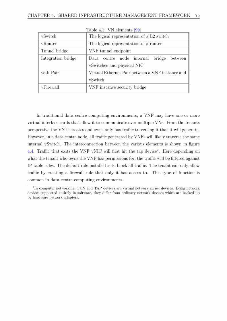
CHAPTER 4. SHARED INFRASTRUCTURE MANAGEMENT FRAMEWORK 75
Table 4.1: VN elements [99]
vSwitch The logical representation of a L2 switch
vRouter The logical representation of a router
Tunnel bridge VNF tunnel endpoint
Integration bridge Data centre node internal bridge between
vSwitches and physical NIC
veth Pair Virtual Ethernet Pair between a VNF instance and
vSwitch
vFirewall VNF instance security bridge
In traditional data centre computing environments, a VNF may have one or more
virtual interface cards that allow it to communicate over multiple VNs. From the tenants
perspective the VN it creates and owns only has traffic traversing it that it will generate.
However, in a data centre node, all traffic generated by VNFs will likely traverse the same
internal vSwitch. The interconnection between the various elements is shown in figure
4.4. Traffic that exits the VNF vNIC will first hit the tap device2. Here depending on
what the tenant who owns the VNF has permissions for, the traffic will be filtered against
IP table rules. The default rule installed is to block all traffic. The tenant can only allow
traffic by creating a firewall rule that only it has access to. This type of function is
common in data centre computing environments.
2In computer networking, TUN and TAP devices are virtual network kernel devices. Being networkdevices supported entirely in software, they differ from ordinary network devices which are backed upby hardware network adapters.

CHAPTER 4. SHARED INFRASTRUCTURE MANAGEMENT FRAMEWORK 76
vNIC
VNF
vBridge port
vFirewall
tap device
veth-tun
Integration bridge
tap device
veth-int
Tunnel bridge
port-tun
GRE/VxLANTUNNELS
Iptables firewall
Figure 4.4: Network Element Interconnection
Assuming a firewall rule exists to allow traffic to exit the VNF, it is sent to the
common vSwitch of the data centre node on the integration bridge. Here the traffic is
only visible to the data centre node and the infrastructure control plane. The integration
bridge is logically separated from all VNF instances precisely so that VNFs have no ability
to sniff the traffic that will traverse the common vSwitch. The datacenter node vSwitch
table rules will send traffic to the tunnel bridge with the tenant ID in order to encapsulate
it into either a GRE or VxLAN tunnel before it can be sent to the physical NIC of the
data centre node. When the traffic is traversing the physical NIC, it has already been
encapsulated and cannot be inspected by any other process running on the node.
VNF Traffic that enters the physical NIC will conversely be encapsulated in a GRE or
VxLAN tunnel with the tenant ID as an identifier. The tunnel bridge then decapsulates
it and sends it to the integration bridge to route the traffic to the destination VNF. The
traffic lastly has to traverse the tenant firewall before it can effectively arrive at the vNIC
of the VNF instance.
This design allows multiple VNFs to run side by side belonging to different tenants
with no chance of any traffic from one tenant being intercepted by another tenant. The
underlay network of the data centre model consists of physical and virtual components.
These components include a hypervisor which is used to schedule and manage a number
of EPC VNFs. A logical representation of isolated tenant networks is illustrated in figure
4.5.
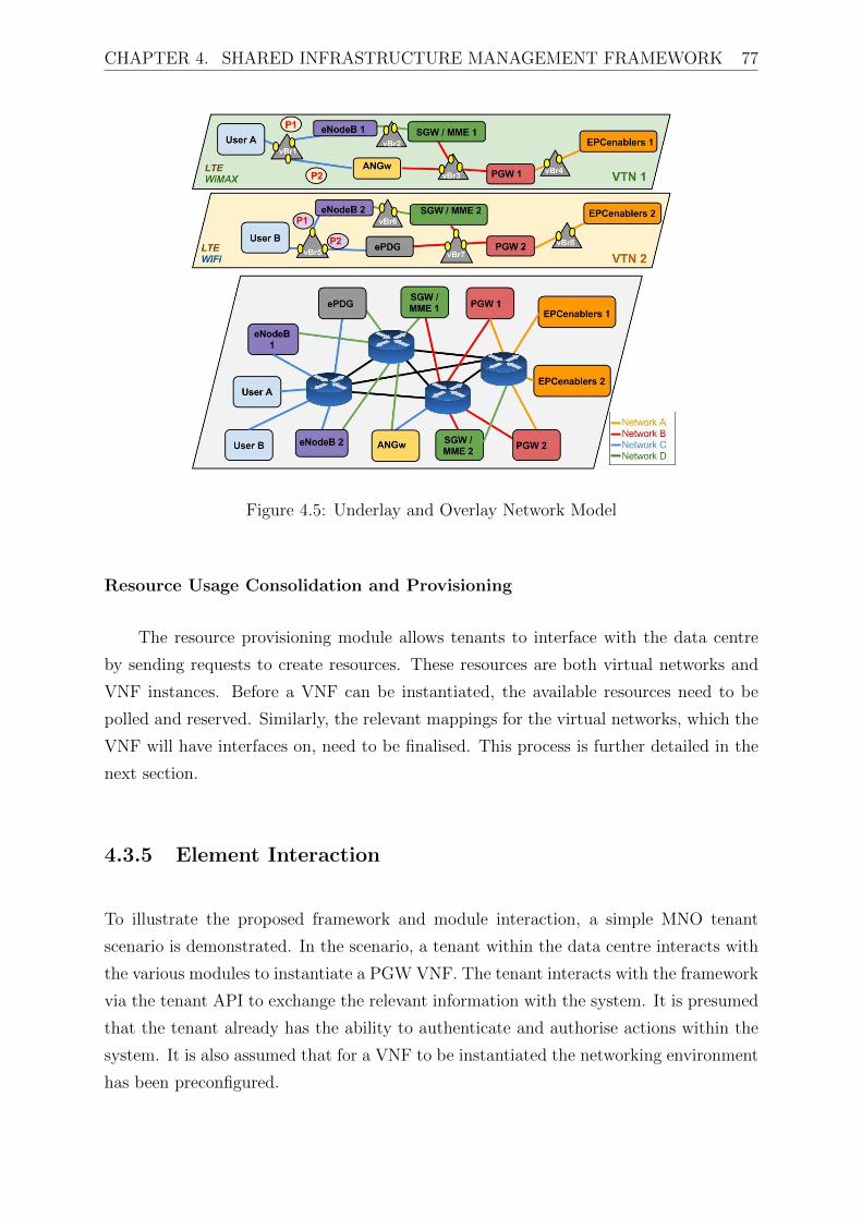
CHAPTER 4. SHARED INFRASTRUCTURE MANAGEMENT FRAMEWORK 77
Figure 4.5: Underlay and Overlay Network Model
Resource Usage Consolidation and Provisioning
The resource provisioning module allows tenants to interface with the data centre
by sending requests to create resources. These resources are both virtual networks and
VNF instances. Before a VNF can be instantiated, the available resources need to be
polled and reserved. Similarly, the relevant mappings for the virtual networks, which the
VNF will have interfaces on, need to be finalised. This process is further detailed in the
next section.
4.3.5 Element Interaction
To illustrate the proposed framework and module interaction, a simple MNO tenant
scenario is demonstrated. In the scenario, a tenant within the data centre interacts with
the various modules to instantiate a PGW VNF. The tenant interacts with the framework
via the tenant API to exchange the relevant information with the system. It is presumed
that the tenant already has the ability to authenticate and authorise actions within the
system. It is also assumed that for a VNF to be instantiated the networking environment
has been preconfigured.

CHAPTER 4. SHARED INFRASTRUCTURE MANAGEMENT FRAMEWORK 78
Referring to figure 4.6, the tenant sends a VNF launch request and appended to
the request, the tenant embeds the launch parameters as shown in figure 4.7. These
parameters include the name to assign to the VNF, the amount of resources to allocate
to it in terms of RAM, processor cores and disk space; the image that the VNF is based
on for example a PGW appliance image; and the number of network attachments to make
for the VNF so that the relevant mappings can be made on the network elements.
Resource Provisioning
Tenant
Resource Allocation Hypervisor
error:CouldNotAllocate
resourcesAvailable()
Network Elements Compute Elements
ProcessResourceInformation
HTTP_POST(vnfLaunchParams)
HTTP_POST
resourcesReservation(request) create(vSwitches)
create(result)
allocate(vCPU,RAM,HD)
createVNFObject()
allocate(result)
launchVNF()
launchVNF(result)HTTPStatusCode(VNFLocation)
HTTP GET(VNFLocation
HTTP Response(VNFStatusValues)
[loop for n vSwitches]install flow tables
Figure 4.6: The Signalling Flow for a VNF Launch Request

CHAPTER 4. SHARED INFRASTRUCTURE MANAGEMENT FRAMEWORK 79
<?xml version="1.0"?>
<VNF_Launch_Params> Jupiter PGW VNF instance Request
<instance_name>PGW</instance_name>
<instance_flavour> default VNF flavour
<RAM>4028 GB</RAM>
<vCPU>2 cores</vCPU>
<HD_size>20 GB</HD_size>
</instance_flavour>
<VNF_image>PGW_IMAGE</VNF_image>
<Network_attachments> vNICs
<VN1_name>
packet_network
<VN1_subnet>packet_network_subnet</VN1_subnet>
</VN1_name>
<VN2_name>
serving_network
<VN1_subnet>serving_network_subnet</VN1_subnet>
</VN2_name>
<VN3_name>
management_network
<VN1_subnet>management_network_subnet</VN1_subnet>
</VN3_name>
</Network_attachments>
</VNF_Launch_Params>
Figure 4.7: VNF Launch Request Parameters
Resource provisioning will extract this information from the request message and
reconcile if the required resources are available. If the resources are not available, over-
subscription will occur as defined by equation 4.1. If the resource provisioning fails an
error is immediately generated that the request cannot be honoured. The hypervisor
then coordinates with the network and compute elements to prepare and reserve the
resources that will be attached the VNF instance. Once the VNF instance is scheduled
for a launch, the hypervisor responds with the result code of the launch request. The
result code, however, does not contain any information about whether the VNF launch
was successful, so the tenant needs to send another request to retrieve information about

CHAPTER 4. SHARED INFRASTRUCTURE MANAGEMENT FRAMEWORK 80
the VNF that was scheduled for creation. The hypervisor can then respond with the
status information on the VNF in a format as shown in figure 4.8.
<?xml version="1.0"?>
<VNF_Launch_Params> Jupiter PGW VNF instance Response
<created>2014-04-09T19:24:27Z</created>
<flavor>default</flavor>
<compute_node>Data Center Node 3</compute_node>
<image>PGW image</image>
<name>PGW</name>
<launched>2014-04-09T19:24:27Z </launched>
<power_state>ON</power_state>
<status>running</status>
<task_state>schedule complete</task_state>
<networks>
<vnic1>packet_network=IPADDR</vnic1>
<vnic2>serving_network=IPADDR</vnic2>
<vnic1>management_network=IPADDR</vnic1>
</networks>
</VNF_Launch_Params>
Figure 4.8: VNF Status Attributes
4.4 Discussions
This chapter has presented the shared infrastructure management framework that allows
for multiple network operators to run EPC VNFs in a data centre. The architecture
defines the generic modules and interworking to provide the required functionality and
isolation of tenants in the data centre. The framework is entirely conformant to ETSI
NFV high-level architecture and a mapping is shown in figure 4.9.

CHAPTER 4. SHARED INFRASTRUCTURE MANAGEMENT FRAMEWORK 81
Figure 4.9: Architectural Alignment
4.4.1 ETSI NFV Compliance
The compliance of the proposed framework architecture with ETSI NFV specifications,
as presented in Section 2.2 and Figure 2.3, is detailed and presented with motivations
below:
• As per the ETSI NFV specification, VMs run the software of network functions
and comprise the VNF and EMS logical entities in the solution architecture. The
specific types of VNFs are stored in the Resource Catalogue as images and once
instantiated can be housed in a stand alone VMs or shared with other VNF entities
in the same VM. The motivation for this mapping is dependant on the functionality
of the VNF. For example, EPC VNFs such as the eNodeB, PGW and SGW are
all housed in standalone VMs due to the varied and complex functionality of the
VNFs. IMS VNFs such as the P-CSCF, I-CSCF, S-CSCF are all housed in one VM
due to the similarity of operations between these network functions.
• The ETSI NFV NFVI entity comprises the totality of hardware and software
entities that VNFs will be deployed over. This is an important and fundamental
architectural component and is mapped to the proposed solution architecture as the
Infrastructure Control Plane, the Network Elements and the Compute Elements.
– The hypervisor entity of the ETSI NFV architecture is directly mapped in the
proposed solution framework.
– The hardware and software Network Elements are directly mapped in the
proposed solution framework.
– The hardware and software Compute Elements are directly mapped in the
proposed solution framework.
– The hardware and software Storage Elements are not directly mapped for
the proposed solution because the NFV elements that are deployed in this

CHAPTER 4. SHARED INFRASTRUCTURE MANAGEMENT FRAMEWORK 82
solution framework are not dependant on specialised storage functionality. For
example, there is no complex database service that is offered via the VNFs,
hence simple ephemeral (non-persistent) hard disk storage mapping sufficed
for the VNFs in the solution architecture.
• The ETSI Management and Orchestration element is directly mapped to the
solution framework. The VIM element of the ETSI NFV architecture corresponds
with the Resource Provisioning, Tenant Authentication and Tenant Authorisation
elements of the solution framework. They provide the means through which a cloud
user or provider can interface with the NFVI (Infrastructure Control Plane, Network
Elements and Compute Elements). The orchestrator functionality is provided to
the cloud users via the Resource Provisioning API and by the advertisement of
resources via the use of templates.
4.4.2 Component System Development
Many of the modules mentioned in the solution architecture existed as single stand alone
software pieces that were incorporated and modified to integrate into the system designed
for this thesis. Table 4.2 describes each module of the solution architecture and how the
design of the module was achieved.

CHAPTER 4. SHARED INFRASTRUCTURE MANAGEMENT FRAMEWORK 83
Table 4.2: System developments
Module Design and Development
Tenant authentication and
authorisation
API module to be implemented that allows the addition
of new users (tenants) and the allocation of permissions.
Resource provisioning and
allocation
API module that would expose to authenticated
users (tenants) the ability to send requests to the
infrastructure control plane.
Network controller and
separation
Designed to be an extension of a traditional SDN
controller. The controller should support integration
with a cloud platform, and support multi-tenancy in
network resource allocation.
Resource usage collection
and consolidation
Designed to reuse a cloud based monitoring application
that is able to specifically retrieve data centre usage
statistics.
Resource catalogue The elements stored in the resource catalogue, for
network function images that need to be preconfigured
and installed with the relevant software.
Clock synchronisation Designed to reuse a network application model of
Network Time Protocol (NTP) daemons running on all
hardware nodes in the data centre.
Hypervisor and resource
monitoring
Designed to reuse an existing hypervisor standard.
Network and Compute
Elements
Should reuse hardware and software implementations of
virtual resources and extended to allow for integration
and control from multiple tenants.
The framework emphasises on ensuring that isolation of resources both networking
and computing is achieved for the benefit of the MNOs utilising the shared infrastructure.
As network functions are implemented as virtualised appliance reduction of costs is
ensured. The drawback is that virtualised appliances operate at reduced performance
compared to their physical counterpart. The next chapter details extensions to the Shared
Infrastructure Management Framework that allows for performance enhancements for
VNFs running in the data centre.

Chapter 5
Performance Enhanced Framework
One of the biggest challenges faced by mobile network service providers will be their
ability to keep their network operations and management costs low while ensuring that
service quality does not deteriorate. This is not a trivial problem as the costs of network
equipment increases and many of the solutions available to network operators rely on the
acquisition of expensive specialised high performance hardware. As the need for achieving
virtualisation and softwarisation of network functions gains momentum, it is increasingly
becoming important to ensure adequate performance for network operators. How a VNF
is designed, implemented, and placed over physical infrastructure can play a vital role on
the performance metrics achieved by the network function. Not paying careful attention
to this aspect could lead to drastically reduced performance of network functions thus
defeating the purpose of embracing virtualisation as a solution.
The challenge of virtualising hardware appliances in general, and network functions
in particular, is to ensure delivery of near native (i.e. non-virtualised) performance.
The findings of the literature review and standardisation activities chapters show that
little research and/or implementation work has been done in the realm of performance
improvements of VNFs in multi-tenant environments. Many of the approaches of
accelerating the performance of VNFs does not consider if these are deployed in multi-
tenant deployments which have strict privacy and security requirements among the
tenants. In this chapter, this work identifies the factors that significantly affect the
performance of different categories of VNFs of a MVNO and propose a placement
framework to achieve high performance for 5G VNFs deployed in multi-tenant data
centres.
84

CHAPTER 5. PERFORMANCE ENHANCED FRAMEWORK 85
5.1 Design Considerations
Several of the requirements and considerations mentioned in the previous chapter equally
apply for the performance enhanced framework. However there are some factors that if
not critically considered would result in extremely reduced performance of VNFs. High
level considerations are influenced by the entirety of the NFV Infrastructure (NFVI)
while VNF considerations are dependant on the individual network functions and how
each operates.
5.1.1 High Level Performance Considerations
Many factors will impact on a data centre in terms of how performance is defined and
achieved depending on the design goals. The following are such examples:
Elasticity and scalability are essential performance requirements that need to be
considered. Increased resource requirements in the data centre should result in a
proportional increase in utilisation. Decreased resources requirements should have the
opposite effect. This should be implemented such that an increase of resource utilisation
(up to a hard limit defined by the total amount of resources available) should not
significantly result in a VNF’s service quality degradation. There are two ways of
implementing scaling of VNFs namely vertical and horizontal scaling. In vertical scaling
one would allocate more resources, such as vCPUs, Random Access Memory (RAM),
or Hard Disk (HD) space, to the VNF. In horizontal scaling, the VNF or resultant
application would be distributed evenly across the data centre hardware nodes depending
on current resource demands. An example of horizontal scaling in the case of many end
users appearing in a single location would be to increase the number of serving gateways
for that locations while load-balancing the connections. Vertical scaling is much easier
to implement however horizontal scaling is the more elegant solution and requires careful
planning. The performance enhanced framework is designed with horizontal scaling in
mind by being able to detect when increased resources are needed and increasing the
number of VNF instances deployed.
The performance enhanced framework should enable dynamic configuration of the
hardware and software components of the data centre. This improves on performance
as manual configuration is not required to deploy VNFs. The framework should cater

CHAPTER 5. PERFORMANCE ENHANCED FRAMEWORK 86
to changes such as auto scaling, failure detection and recovery, and resource discovery
to adapt to changing environments, faults, and workload volumes. The performance
enhanced framework is optimised to take into account usage patterns. Aside from
the allocation and deallocation of resources to individual tenants in the data centre,
other operations can impact the load perceived by the management and operational
infrastructure. These include, for example, the polling of resources available and utilised
which entails the gathering of fine grain details about the state of the data centre. The
performance enhanced framework defines metrics to measure such impacts which are
shown in the results and evaluations chapter.
5.1.2 VNF Specific Considerations
Each network function performs specific and specialised operations. Thus for improved
network function optimisation, each network function (i.e. per MTC function, eNodeB,
SGW, PGW, ePDG, IMS and other signalling intensive functions) is enhanced in a case
by case manner. The performance enhanced framework should be able to deploy VNFs
regardless of the underlying infrastructure. VNFs should operate with their required
performance targets in these different environments by being able to specify the bare
minimum required. In the development of the performance enhanced framework, the
most important factors that affect the performance of the different types of network
functions offered in a cloud were identified.
The packet gateway functions (SGW and PGW) perform compute intensive
operations and this presents a huge challenge when they have to run as VNFs.
Traditionally these types of network functions benefit greatly from being run on
proprietary dedicated hardware but as solutions move to software only implementations
a reduction in performance is observed. Compute intensive VNFs are not able to achieve
a high performance when they run as software-only entities. As NFV aims to offer
functions as software-only instances some solutions have to be presented to overcome
this disadvantage. The performance enhanced framework aims to deploy VNFs with a
reduced hypervisor abstraction in order to achieve increased performance.
The biggest challenge of virtualising base station functions (such as the eNodeB) is
the compute-intensive baseband function of the physical layer (Layer 1) which is typically
implemented on dedicated modern hardware and processors. In this case, Layer 1 software
could be virtualised and running as a VM on high volume servers, in conjunction with
CHAPTER 5. PERFORMANCE ENHANCED FRAMEWORK 87
other hardware acceleration mechanisms in the network interfaces. Base station functions,
similar to the packet gateways functions, could also benefit from fast packet processing
and reduced hypervisor abstraction. While virtualising the base station functions is
out of scope for this thesis, as the required dedicated hardware was not available to
showcase improvements, the base station functions were virtualised in terms of their
control functionalities. The access network capabilities were then emulated to complete
the mobile network use case implementation.
Massive amounts of traffic is expected to traverse through IMS-related and PCC
functions. These types of network functions handle high numbers of signalling traffic
for network end users. Load balancing and network acceleration can improve the VNF
performance of both the virtual switches and host server physical NICs.
The ePDG is used to secure the connection to user equipment over untrusted non-
3GPP access infrastructure (usually public WiFi) via IPsec tunnels. This requires
the network function to perform complex cryptographic algorithm processing for each
connection. Drastic reduction of performance can be expected if this network function
is virtualised without any acceleration capabilities. These types of VNFs would benefit
from access to hardware acceleration and/or software optimisation for the cryptographic
workload throughput. The IPsec stack in the ePDG should be developed to leverage
cryptographic algorithm acceleration via a virtualised function driver.
Another profile of functions utilised widely by network operators in are content
providing functions. These includes streaming video, streaming audio, viewing
photographs, or accessing any other cloud-based data repository distributed to a large
number of end users. Multimedia services have high bandwidth requirements, with strict
requirements for latency, jitter, and packet loss in order to ensure Quality of Experience
(QoE) for end users. Newer audio and video codecs require more processing resources
than previously available. Transcoding focused acceleration should be used for these
functions if they are to be virtualised.
5.2 Performance Enhancement
The NFV Infrastructure (NFVI) includes the totality of all hardware and software
components that builds up the environment in which VNFs are deployed. As we have

CHAPTER 5. PERFORMANCE ENHANCED FRAMEWORK 88
shown in the previous section, some VNFs will require some form of acceleration to meet
their performance goals. Compared to virtualisation in the IT industry, telco oriented
virtualisation needs to support an extensive range of NFV use cases [10]. The different
types of services implemented on a telco cloud include Voice over LTE (VoLTE), Content
Distribution Networks (CDN), MTC, and High Definition video streaming.
The performance enhanced framework is designed to use existing network elements
that have been defined by the relevant SDOs, in this case ETSI NFV. As described
by ETSI [100], different types of heterogeneous accelerators can be implemented. ETSI
defines new elements for the adaptation of specific network functions at the three relevant
layers as illustrated in figure 5.1.
Figure 5.1: NFV ETSI Acceleration Layers
Coherent acceleration can bypass the hypervisor of virtualisation infrastructure
completely as a way to overcome the performance bottleneck introduced by the inherent
functions of the hypervisor. This entails the VNF software components being able to
directly access and execute the accelerated functions in hardware present in the node
hosting the VNF i.e. the Compute Node (CN). When classifying and identifying the
types of acceleration methods to be used, multiple criteria needs to be considered:
• What type of software or VNF is going to take advantage of the acceleration?
• What is the type of acceleration method used (hardware, software, heterogeneous,
coherent)?
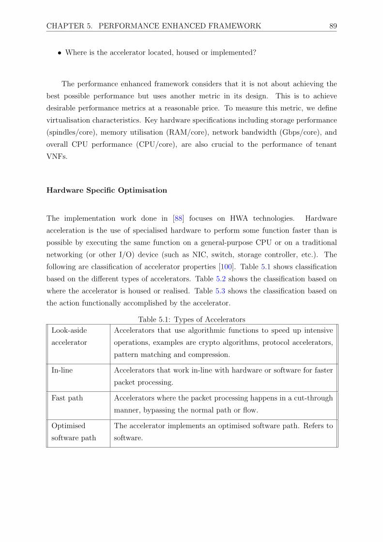
CHAPTER 5. PERFORMANCE ENHANCED FRAMEWORK 89
• Where is the accelerator located, housed or implemented?
The performance enhanced framework considers that it is not about achieving the
best possible performance but uses another metric in its design. This is to achieve
desirable performance metrics at a reasonable price. To measure this metric, we define
virtualisation characteristics. Key hardware specifications including storage performance
(spindles/core), memory utilisation (RAM/core), network bandwidth (Gbps/core), and
overall CPU performance (CPU/core), are also crucial to the performance of tenant
VNFs.
Hardware Specific Optimisation
The implementation work done in [88] focuses on HWA technologies. Hardware
acceleration is the use of specialised hardware to perform some function faster than is
possible by executing the same function on a general-purpose CPU or on a traditional
networking (or other I/O) device (such as NIC, switch, storage controller, etc.). The
following are classification of accelerator properties [100]. Table 5.1 shows classification
based on the different types of accelerators. Table 5.2 shows the classification based on
where the accelerator is housed or realised. Table 5.3 shows the classification based on
the action functionally accomplished by the accelerator.
Table 5.1: Types of Accelerators
Look-aside
accelerator
Accelerators that use algorithmic functions to speed up intensive
operations, examples are crypto algorithms, protocol accelerators,
pattern matching and compression.
In-line Accelerators that work in-line with hardware or software for faster
packet processing.
Fast path Accelerators where the packet processing happens in a cut-through
manner, bypassing the normal path or flow.
Optimised
software path
The accelerator implements an optimised software path. Refers to
software.

CHAPTER 5. PERFORMANCE ENHANCED FRAMEWORK 90
Table 5.2: Accelerator LocationCPU Instruction
based
The acceleration function is part of the processor instruction set.
Integrated CPU The accelerator is housed as a hardware function within the CPU
socket.
Integrated NIC The accelerator is housed as part of the physical NIC.
Network
attached
The accelerator is accessible through the network.
Bus attached The accelerator functionality is accessible through a bus.
Memory slots A memory device provides the acceleration function.
Processor
interconnects
The accelerator is attached to the processor interconnects.
Table 5.3: Accelerator Functionality Type
Security function such as cryptographic accelerator, IPsec, SSL, Secure RTP, etc.
Compression and/or decompression accelerator (eg for transcoding).
Packet processor for fast path and data plane processing.
Function based packet processor e.g. secure Layer 2, secure Layer 3, packet
processor, eNodeB packet processor etc.
Layer 1 accelerator (e.g. DSP, transcode).
Pattern matching such as Deep Packet Inspection or lawful interception.
Software Specific Optimisation
The scope of the acceleration implemented in the performance enhanced framework is
restricted to the software optimisation domain. Software acceleration provides a set of
one or more optional software layers that are selectively added within elements of an
NFV deployment to augment or bypass native software within a solution. Together,
these new layers bring improved capabilities (e.g. increased network throughput,
reduced operating overhead) which result in measurable improvements over standard,
un-accelerated implementations.

CHAPTER 5. PERFORMANCE ENHANCED FRAMEWORK 91
5.3 Solution Architecture
The Performance Enhanced Framework is illustrated in figure 5.2. It is a direct extension
of the shared infrastructure management framework introduced in the previous chapter.
The goals of how the framework was developed is explained in the following sections.
VNF VNF VNF
Virtual Compute Virtual Network
ComputeHardware
NetworkHardware
Virtualisation Layer
NFV Management
and Orchestration
Virtual Network Functions (VNFs)
NFVI
Hardware Resources
VA Driver
VA Driver
VA Driver
Virtual Accelerator Virtual Accelerator
Hypervisor bypass
VNF Accelerator Mapping and Orchestration
Figure 5.2: Modified NFVI Architecture
5.3.1 Bypass the Hypervisor
The first objective of the performance enhanced framework was to bypass the hypervisor
for improved VNF performance. Two options were considered for this. The first
was to incorporate container provisioning of VNFs, the second was to integrate bare

CHAPTER 5. PERFORMANCE ENHANCED FRAMEWORK 92
metal provisioning of VNFs. In the multi-tenancy use case, security and isolation are
important factors as multiple tenants are sharing common physical resources. While
containers provide faster lifecyles compared to virtual machines, as there are no boot-up
times, containers are primarily a segregated name-space of processes1, hard disk mounts,
virtual interfaces and users. The drawback of containers is they can offer significantly
reduced security isolation compared to virtual machines as VMs are standalone instances
managed by a hypervisor. For this reason bare metal provisioning was developed and
will be described shortly. In the previous chapter VNFs are deployed as VM instances
that run the VNF software that can be deployed in a data centre and managed by
a hypervisor service. This is not ideal when there are high performance requirements
required for the VNFs, which could benefit by making the most of the physical or
underlying infrastructure. Bare metal provisioning can make the VNFs use the hardware
directly by deploying a sectionalised physical machine rather than a virtualised instance
on the hypervisor. The different virtualisation architectures are illustrated in figure 5.3.
Hypervisor
HW
VM
OS
VNF
Baremetal host
VM
OS
VNF
Baremetal host
VM
OS
VNF
Baremetal hos
VM
OS
VNF
HWHW
Container 1Separated by PID/namespaces
Container nSeparated by PID/namespaces
VM
OS
VNF VM
OS
VNF
Hypervisor virtualisation
Baremetal virtualisation
Container virtualisation
OS
Figure 5.3: Virtualisation Approaches
In place of the hypervisor service, a bare metal service interworks with the resource
provisioning service. The bare metal service receives requests from the different tenants
to launch bare metal virtual machines that will in turn run the VNF software. Unlike
traditional virtual machines, bare metal virtual machines are preconfigured with physical
1A name-space in this context is group of processes (running under the umbrella of a parent container)in which each process is a child to the parent container, while similar processes could be running underthe umbrella of other parent containers in the space of the same OS.

CHAPTER 5. PERFORMANCE ENHANCED FRAMEWORK 93
resources. The resource catalogue is updated with the list of available hardware resources
on individual compute nodes. The resource catalogue is also updated to include the list
of preconfigured bare metal virtual machines that can host VNFs. Each type of bare
metal interaction with actual hardware, such as power on/off, boot, interactions with
RAM, cores etc., is wrapped with a driver. This driver allows the provisioned bare
metal instances to utilise the underlying physical hardware without the intervention
of a hypervisor. The infrastructure manager includes the list of all hardware on a
compute node to the database. The bare metal service makes mappings between the
available hardware resources and the drivers needed to interface with the hardware to
create bare metal hosts. Bare metal hosts are always existing, regardless of whether
they have been bound to a VNFs instance or not. An individual tenant can launch a
bare metal VNF instance in much the same way as previously done with some small but
significant differences. The first difference is that when the tenant makes a request to
launch a VNF, instead of the resource provisioning and allocation modules discovering
if individual resources (vCPU, RAM, HD) are available, the bare metal service can
immediately respond to whether a bare metal host that satisfies the request is available
or not. A bare metal host if considered to be available if it has not been claimed by
any of the tenants to host a VNF. If a bare metal host is available, the bare metal
service has to perform a binding between the VNF template type included in the request
and the bare metal host. The host needs to fulfil the minimum requirements of the
VNF template requested otherwise binding will be unsuccessful. If the host matches the
VNF request template, the host is then prepared for reservation by creating the required
virtual network interfaces for the VNF guest. The bare metal virtual machine can then
be launched with the characteristics included in the request template. The sequence of
actions in the binding process is shown in figure 5.4.

CHAPTER 5. PERFORMANCE ENHANCED FRAMEWORK 94
Resource Provisioning
Tenant
Resource Allocation Baremetal Service
error:noHostsAvailable
acquireBaremetalHost()
Hardware
ProcessResourceInformation
HTTP_POST(vnfLaunchParams)
HTTP_POST
baremetalHost(request) bind(BMhost,VNFImage)
bind(result)
launchBMVNF()
launchBMVNF(result)HTTPStatusCode(BMVNFLocation)
HTTP GET(VNFLocation)
HTTP Response(VNFStatusValues)
Process host requestbind to VNF ImagePrepare n veth
Figure 5.4: The Signalling Flow for a Bare Metal VNF Launch Request
The following model describes the relationship between physical resources (Compute
Nodes) and virtual resources (Virtual Machines) in the data centre. The data centre has
a fixed number of compute nodes CNi (i = 1,2,...,n). Each CN can have a fixed number
of VMs whereVMij (j = 1,2,...,m) is the jth VM residing on the ith CN in the data centre.
To denote a VM which belongs to a particular tenant we use VMaij for tenant a, and
similarly VMbij for tenant b. One thing to note is that in this model, each compute node
has a fixed number of VMs it can support unlike the previous chapter where the number
of VMs that can be supported is defined by the over-subscription equation. Figure 5.5
shows the basic model for data centre compute nodes and their corresponding bare metal
virtual machines. This is because on each compute node we pre-provision the bare metal
virtual machines, and the virtual machines exist regardless of whether they are in use

CHAPTER 5. PERFORMANCE ENHANCED FRAMEWORK 95
or not. The determining factor of whether a bare metal virtual machine will host a
VNF is if the bare metal host satisfies the minimum requirements of the VNF template.
This requires a pre-matching algorithm to find a suitable compute node that contains a
bare metal virtual machine hosts that satisfies these requirements. Algorithm 1 gives the
pseudo code that determines bare metal matching.
VM1
CN1
VM2 VMm
VM1
CN2
VM2 VMm
VM1
CNn
VM2 VMm
Figure 5.5: Data centre compute nodes model
Algorithm 1 Function acquireBaremetalHost()
1: procedure acquireBaremetalHost()
2: vCPU← number of virtual cores
3: RAM← in megabytes, amount of RAM
4: Disk← in gigabytes, amount of HD
5: n← number of CNs
6: m← number of bare metal VMs
7: find matching bm host :
8: for (i = 1; i <= n; i + +) do
9: for (j = 1; j <= m; j + +) do
10: if (
11: (VMij.vCPU >= vCPU) & (VMij.RAM >= RAM) &
12: (VMij.HD >= Disk) & (VMij.bound == False)
13: ) {14: goto bind . exit the loop, retain values of i and j
15: }
16: bm host match not found :
17: return NULL
18: bind :
19: VMij.bound = True
20: return VMij

CHAPTER 5. PERFORMANCE ENHANCED FRAMEWORK 96
Because different bare metal hosts share physical resources, more specifically network
interfaces, and with no hypervisor to enforce separation all interactions on the underlying
network hardware will be visible to all tenants utilising the hardware. There is currently
no implemented solution that can overcome this major limitation as bare metal is seen as
a solution for single tenancy. Our solution to overcome this is to provide network traffic
isolation through firewalling on local compute node VMs belonging to different tenants
and tunnelling mechanisms such GRE and VxLAN for VNF traffic that will travel across
the data centre. These mechanisms of providing isolation are integrated and extended as
part of the performance enhanced framework.
5.3.2 Accelerate Virtualised Network Resources
The second objective of the performance enhanced framework was to accelerate the
virtualised network resources and achieve increased packet processing performance in
the data centre. Accelerating vCPUs is relatively easy, as all that is needed is to specify
the correct driver for the VNF launched that maps to the underlying hardware. This
allows the bare metal VNF to experience improved performance as there is no hypervisor
to act as an intermediary.
Accelerating the virtual NICs proved to be a complicated task due to many intricacies
involved in the implementation of virtual switches in virtualised environments. In terms
of implementation approaches, cloud infrastructure managers can either use the Linux
Bridge [101] or Open vSwitch (OVS) [102] implementation options. Linux Bridge is a
fast and reliable virtual switching solution. Its drawbacks are that it lacks sophisticated
control, configuration and monitoring capabilities. OVS was designed specifically to make
the management of VM network configurations easier. Another advantage of OVS over
Linux Bridge is that OVS is designed to be interfaced with a SDN controller whereas
Linux Bridge is not SDN ready. For these reasons OVS is integrated into the solution
framework. The architecture of OVS is shown in figure 5.6.

CHAPTER 5. PERFORMANCE ENHANCED FRAMEWORK 97
Figure 5.6: The Interfaces and Components of OVS [103]
In the reference OVS architecture, two components are involved in the direct packet
forwarding. The first is the ovs-vswitchd, a userspace daemon; the second is a datapath
kernel module. The first packet of a flow, which can originate from a physical NIC or a
VM’s virtual NIC, results in a table miss, and the kernel module directs the packet to the
userspace component which caches the forwarding decisions for subsequent packets into
the kernel. In a simple configuration of the OVS this is the general sequence of events.
The problem with this configuration is that traffic in this configuration is traversing a
flat (non-segregated) network topology i.e all traffic is visible to all tenants of a data
centre. Firewalling and Tunnelling need to be integrated in the solution to allow for
traffic isolation among the tenants.
Recall the virtual network components introduced in the previous chapter. Figure
5.7 illustrates the virtual network components as well as their operating space. A packet
originating from a VNF exits the virtual NIC of the VM and enters the firewall tap
device. Here user space iptable2 rules provide firewall isolation between different tenants.
Next the packet has to enter kernel space for forwarding to the appropriate port. Possible
ports include going to a VM on the same physical node (another virtual NIC), or to a
VM on another node (hence exiting a physical NIC). Flow table rules or normal Layer 2
forwarding rules will apply and a virtual switch called the integration bridge implements
flow matching rules that determine where a packet will go. If the packet is destined
for a local VM (east-west traffic) it will exit back into user space into the firewall tap
device of the corresponding VM. If the packet is destined to a remote VM on another
CN (north-south traffic) it will go to another virtual switch called the tunnel bridge to
be encapsulated before it can finally exit the physical NIC of the host machine.
2iptables is a user-space application program that allows a system administrator to configure thetables provided by the Linux kernel firewall (implemented as different Netfilter modules) and the chainsand rules it stores. Rules include what traffic to drop or allow to pass through.

CHAPTER 5. PERFORMANCE ENHANCED FRAMEWORK 98
vNIC
VNF
vBridge port
vFirewall
tap device
veth-tun
Integration bridge
tap device
veth-int
Tunnel bridge
port-tun
GRE/VxLANTUNNELS
Iptables firewall
User space element
Kernel space element
Key
Figure 5.7: Virtual Network Resources and Operating Spaces
Tunnelling solutions (such as GRE and VxLAN) involve the traversal of traffic
processing from kernel space to user space of the host server kernel module has no
information about tenants and their respective VLAN identifiers. Further, complications
arise when multi-tenancy requires traffic isolation for VNFs and some of these functions
need to be implement in kernel space of the host server. This could result in traffic
traversing from a VNF to user space processing, to kernel processing and back to user
space processing hence incurring huge delays, which could result in drastically poor
performance.
Hypervisors have played an important role in bridging traffic between VMs and the
outside world, while providing isolation in multi-tenant environments. If not planned
appropriately, virtual switches operating entirely in user space without the assistance
of a hypervisor, offer no isolation to tenants. The performance enhanced framework is
hypervisor bypass leaving traffic firewalling completely unmanaged. Our multi-server
and multi-tenant environment additionally requires the infrastructure support for virtual
networking using VxLAN, GRE and VM tenant isolation. Some of these functions require
kernel capabilities while others require user space capabilities. For secure datapath
processing in user space, packets still have to traverse through the kernel (sometimes
more than once) to utilise these capabilities. This could result in degraded performance
as the traffic path is not optimised.
The solution is to pick a location to perform all virtual switching functions. The two
obvious options are to handle all virtual switching in either user space or in kernel space.
Both approaches discussed below were investigated and implemented in the solution

CHAPTER 5. PERFORMANCE ENHANCED FRAMEWORK 99
framework.
5.3.3 User Space Virtual Switching
In this approach, the objective was to re-vector all network traffic to traverse outside
of the Linux kernel into the user space process (ovs-vswitchd). The expected advantage
of this will be improved performance over the native virtual switch implementation as
traffic no longer traverses through each space for each individual function. The VNFs
will need to be updated on how to interface with the virtual switch for interworking to
be successful.
The Data Plane Development Kit (DPDK) is a tool that OVS can make use of
to achieve user space data processing [104]. The DPDK library allows OVS to operate
entirely in user space by making use of hugepages3 for the large memory pool allocation
used for packet buffers. By using hugepage allocation, performance is increased since
fewer pages are needed, and therefore less Translation Lookaside Buffers (TLBs, high
speed translation caches), which reduces the time it takes to translate a virtual page
address to a physical page address, which without hugepages, high TBL miss rates would
occur with the standard 4k page size, slowing performance.
The implications are as follows: the default action of OVS is kernel space datapath
traffic processing. Using the DPDK library allows us to move this action to user space.
However, the default action of tunnelling is through the kernel space datapath. This
is a separate action from the kernel space datapath processing, as tunnel encapsulation
prepares the packet to be sent out the physical NIC in kernel space. To integrate with
bare metal provisioning and for fast packet processing we implemented tunnelling and
firewalling in user space. At the time of implementation and writing of this thesis this
was not yet done in any other work.
Figure 5.8 gives the macroscopic view of the compute node internal virtual network
3An operating system uses pages as the basic unit of memory, where physical memory is partitionedand accessed using the basic page unit. The default page size is 4096 bytes on most architectures. Linuxuses “Translation Lookaside Buffers” (TLB) in the CPU architecture. These buffers contain mappingsof virtual memory to actual physical memory addresses. So utilising a huge amount of physical memorywith the default page size consumes the TLB and adds processing overhead. Hugepages allows largeamounts of memory to be utilised with a reduced overhead. The Linux kernel will set aside a portion ofphysical memory to be able to be addressed using a larger page size. Since the page size is higher, therewill be less overhead managing the pages with the TLB.

CHAPTER 5. PERFORMANCE ENHANCED FRAMEWORK 100
interconnections. As modelled in the previous section, the number of compute nodes is
CNi (i = 1,2,...,n). Each CN can have a fixed number of VMs whereVMij (j = 1,2,...,m)
is the jth VM residing on the ith CN.
CNI virtual ethernet
pair
Tunnel bridge
patch-int
Physical NIC
tun1 tun2 tun (n-1)
vNic vNic
Virtual Switch
Legend
External tunnel
Integration bridge with OF firewall rules
VM1eth0
vhu1
VM2eth0
vhu2
VMmethxx
vhuxx
patch-tun
ethxx
vhu3
Kernel Space
User Space
Figure 5.8: Compute Node Internal Virtual Network Components in User Space
A virtual machine can have one or more virtual interfaces (denoted by vhu) which
complicates the internal network. The integration bridge will have an interface for all
interfaces originating from all virtual machines. Additionally, the integration bridge
virtual switch has a single virtual Ethernet connection with the tunnel bridge. Therefore
the number of virtual interfaces on the integration bridge is given by equation 5.1:
(n∑
i=1
m∑j=1
VMivhuj) + 1 (5.1)
• VMi is the ith VM of a CN
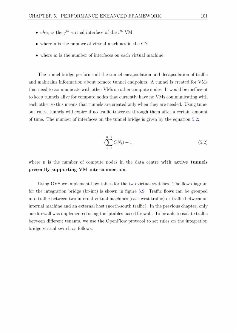
CHAPTER 5. PERFORMANCE ENHANCED FRAMEWORK 101
• vhuj is the jth virtual interface of the ith VM
• where n is the number of virtual machines in the CN
• where m is the number of interfaces on each virtual machine
The tunnel bridge performs all the tunnel encapsulation and decapsulation of traffic
and maintains information about remote tunnel endpoints. A tunnel is created for VMs
that need to communicate with other VMs on other compute nodes. It would be inefficient
to keep tunnels alive for compute nodes that currently have no VMs communicating with
each other so this means that tunnels are created only when they are needed. Using time-
out rules, tunnels will expire if no traffic traverses through them after a certain amount
of time. The number of interfaces on the tunnel bridge is given by the equation 5.2:
(n−1∑i=1
CNi) + 1 (5.2)
where n is the number of compute nodes in the data centre with active tunnels
presently supporting VM interconnection.
Using OVS we implement flow tables for the two virtual switches. The flow diagram
for the integration bridge (br-int) is shown in figure 5.9. Traffic flows can be grouped
into traffic between two internal virtual machines (east-west traffic) or traffic between an
internal machine and an external host (north-south traffic). In the previous chapter, only
one firewall was implemented using the iptables-based firewall. To be able to isolate traffic
between different tenants, we use the OpenFlow protocol to set rules on the integration
bridge virtual switch as follows.

CHAPTER 5. PERFORMANCE ENHANCED FRAMEWORK 102
Packet enters br-int
table 0
table 1
table 2
table 3
To External
To VM
Drop
table 24
Normal
0-1
0-3
3-external
2-VM
0-24
24-normal
1-2
1-drop
Figure 5.9: Integration bridge flow table
An incoming packet is it will be matched against table 0. If the packet is an
Address Resolution Protocol (ARP) packet, it will be passed on to table 24 (0-24 in
the diagram) for priority handling. Table 24 forwards the packet to exit flow mode into
normal processing (24-normal in the diagram). Normal processing is implemented as a
typical Layer 2 learning switch that operates on Media Access Control (MAC) address
to port mappings. When the packet first arrives, its source MAC address is compared to
the current forwarding table. If the source is unknown (the MAC address is not in the
current forwarding table) the MAC address is added to the table with the port number
the packet originated from. It then compares the destination MAC address to the table of
known MAC addresses. If there is a match, the packet is forwarded to the corresponding
port. If the destination MAC address is not known, the packet is flooded to all ports
(except the port it originated from).
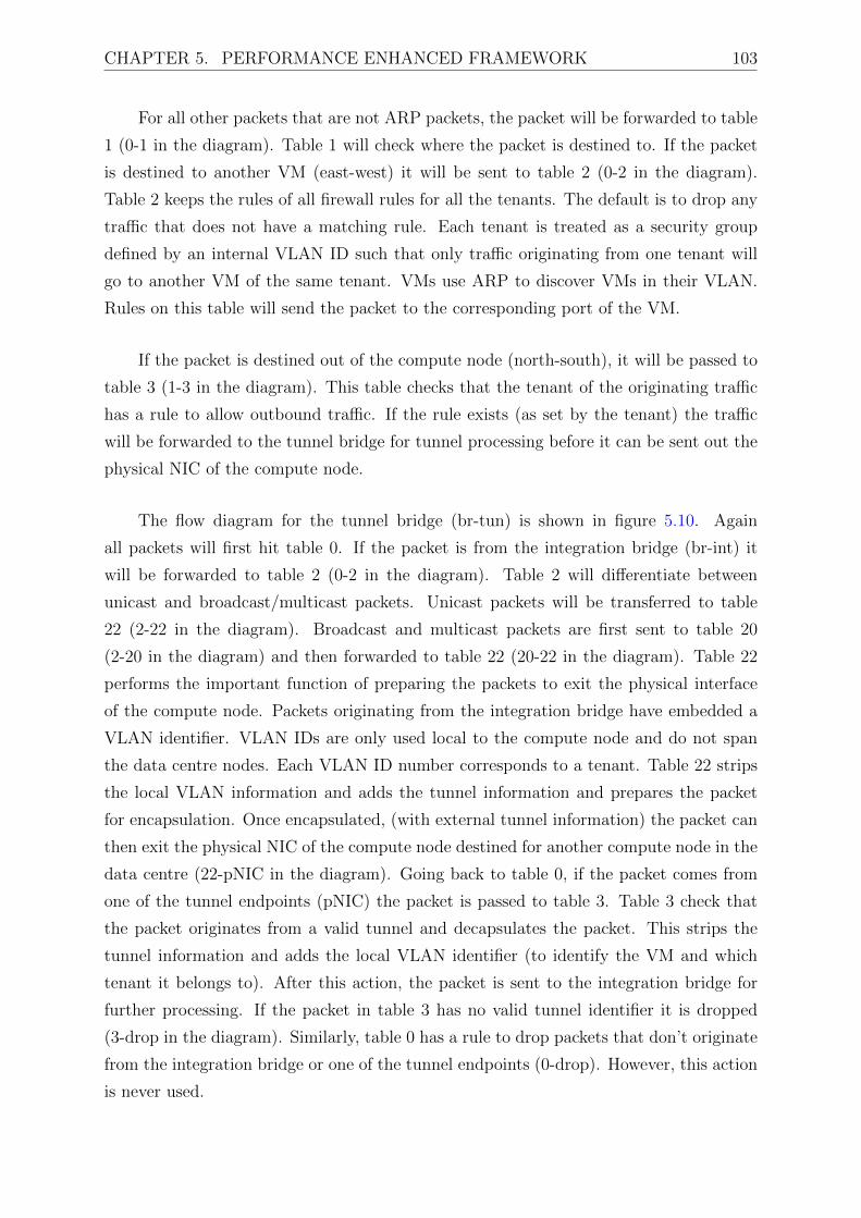
CHAPTER 5. PERFORMANCE ENHANCED FRAMEWORK 103
For all other packets that are not ARP packets, the packet will be forwarded to table
1 (0-1 in the diagram). Table 1 will check where the packet is destined to. If the packet
is destined to another VM (east-west) it will be sent to table 2 (0-2 in the diagram).
Table 2 keeps the rules of all firewall rules for all the tenants. The default is to drop any
traffic that does not have a matching rule. Each tenant is treated as a security group
defined by an internal VLAN ID such that only traffic originating from one tenant will
go to another VM of the same tenant. VMs use ARP to discover VMs in their VLAN.
Rules on this table will send the packet to the corresponding port of the VM.
If the packet is destined out of the compute node (north-south), it will be passed to
table 3 (1-3 in the diagram). This table checks that the tenant of the originating traffic
has a rule to allow outbound traffic. If the rule exists (as set by the tenant) the traffic
will be forwarded to the tunnel bridge for tunnel processing before it can be sent out the
physical NIC of the compute node.
The flow diagram for the tunnel bridge (br-tun) is shown in figure 5.10. Again
all packets will first hit table 0. If the packet is from the integration bridge (br-int) it
will be forwarded to table 2 (0-2 in the diagram). Table 2 will differentiate between
unicast and broadcast/multicast packets. Unicast packets will be transferred to table
22 (2-22 in the diagram). Broadcast and multicast packets are first sent to table 20
(2-20 in the diagram) and then forwarded to table 22 (20-22 in the diagram). Table 22
performs the important function of preparing the packets to exit the physical interface
of the compute node. Packets originating from the integration bridge have embedded a
VLAN identifier. VLAN IDs are only used local to the compute node and do not span
the data centre nodes. Each VLAN ID number corresponds to a tenant. Table 22 strips
the local VLAN information and adds the tunnel information and prepares the packet
for encapsulation. Once encapsulated, (with external tunnel information) the packet can
then exit the physical NIC of the compute node destined for another compute node in the
data centre (22-pNIC in the diagram). Going back to table 0, if the packet comes from
one of the tunnel endpoints (pNIC) the packet is passed to table 3. Table 3 check that
the packet originates from a valid tunnel and decapsulates the packet. This strips the
tunnel information and adds the local VLAN identifier (to identify the VM and which
tenant it belongs to). After this action, the packet is sent to the integration bridge for
further processing. If the packet in table 3 has no valid tunnel identifier it is dropped
(3-drop in the diagram). Similarly, table 0 has a rule to drop packets that don’t originate
from the integration bridge or one of the tunnel endpoints (0-drop). However, this action
is never used.

CHAPTER 5. PERFORMANCE ENHANCED FRAMEWORK 104
Packet enters br-tun
table 0table 2
droptable 20
table 22
table 3
table 10
physical NIC br-int
0-2 0-3
0-drop
2-20
20-22
2-2222-pNIC
3-10
10-int
3-drop
Figure 5.10: OVS tunnel bridge flow table
5.3.4 Kernel Space Virtual Switching
In this approach, the objective was to re-vector all network traffic to traverse inside of the
Linux kernel. OVS was not well suited to implement this because ovs-vswitchd is stricly
a user space daemon and offers no controllability in the kernel. By using and extending
a tool called IOVisor eXpress Data Path (XDP), the performance enhanced framework
is able to deploy kernel modules that mimic the action of switches in user space.
Figure 5.11 illustrates the internal networking of kernel space switching. VM
interfaces are implemented directly in kernel space and are mapped directly to the
dataplane of the kernel. In this model there is no longer a concept of a virtual switch, but
rather of the data plane that we are directly able to program using APIs that reside in the
user plane. The data plane implements network services as individual kernel modules,
called Input Output Modules (IOModules), that can be translated to our traditional
view of virtual switches in the user plane. These modules can be programmed to provide
switching, routing, firewalling and tunnelling capabilities.

CHAPTER 5. PERFORMANCE ENHANCED FRAMEWORK 105
CNI Kernel tap device
Physical NIC
vNic
Kernel Datapath
Legend
API to IOModules
Kernel SpaceUser Space
Data Plane
VM1
tap1
VM2
tap2
VMm
tapxxtap3
Local Network Controller and DB
l2-int
l2-tun
l2-int
l2-tun
l2-int
l2-tun
l2-int
l2-tun
l2-switch IOModule
Figure 5.11: Compute Node Internal Virtual Network Components in Kernel Space
In user space switching we implemented the flow rules for two virtual switches (the
integration bridge and the tunnel bridge); these two switches are shared in the compute
node such that all tenant traffic will traverse through them. In kernel space, we have the
ability to implement a separate set of switches per tenant. This allows each tenant to have
a separate logical instance of these switches. While the control plane of the forwarding
logic remains the same (an integration bridge to interconnect east-west traffic, and a
tunnel bridge for north-south traffic), these rules can remain the same, except instead of
being forwarded to virtual switches, they are stored on a database that the local network
controller is able to translate to the equivalent code to run as kernel modules in the kernel
data path.
The IOVisor project had already implemented modules that represent a Layer 2
switch and a Layer 3 router. Using these as a basis, we additionally developed modules
to create the tunnel bridge module that could map different tenant ID information stored
in the user space to provide logical separations in the kernel data path. We reused the
Layer 2 switch to implement the integration bridge, whose function remains identical. A
firewall entity is not required as each tenant has their own integration and tunnel bridges.
This setup ensures that VMs belonging to the same tenant can communicate with each
other, but not with other tenants unless interconnected by a Layer 3 router.

CHAPTER 5. PERFORMANCE ENHANCED FRAMEWORK 106
Each Layer 2 switch has a name, type, tenant identifier, and network identifier, as
tenants can have multiple virtual networks. A local database of this information is stored
on the CN for local routing of packets. To enable tunnelling of externally routed packets
the local network controller has an interface to the datacentre network controller service.
The data centre network controller service has all the information about the routing table
database of all the nodes. When a VM is launched, relevant information is propagated
to the network controller such that it has a complete view of the virtual networks on
all compute nodes in the data centre. When a packet needs to leave a VM of one CN
destined for a VM of another CN, the local network controller requests information about
tunnel end point address of the remote VM by providing the tenant ID and network ID or
the local VM. The controller can then perform a lookup on its database of VM locations
and CN addresses and respond with the CN IP address of where the VM is located. This
then allows the local network controller to insert a forwarding rule on the l2-tun switch
of the source VM for future communication. The controller can also, at the same time,
push to insert a rule at the destination CN so that the reverse rules are installed as well.
This learning action is shown in figure 5.12.
Local Network Controller
request_exit_rule(vm_local_ip,
vm_remote_ip)
Data CentreNetwork Controller
Remote NetworkControllerLocal l2-tun Remote l2-tun
request_exit_rule(tenantID,networkID,
vm_local_ip,vm_remote_ip,
requestID)Database lookup()
respond_exit_rule(requestID,
remote_CN_ip)respond_exit_rule(remote_CN_ip)
install exit ruleinstall return rule
push_entry_rule(tenantID,networkID,
vm_local_ip,vm_remote_ip,
requestID)
push_entry_rule(tenantID,networkID,
vm_local_ip,vm_remote_ip,
requestID) install exit ruleinstall return rule
Figure 5.12: Kernel Space Tunnelling Lookup via the Data Centre Network Controller
In summary, both user space and kernel space data path processing were implemented
as each showed great promise for performance improvements. In the data centre
networking community, these two approaches are considered rivals. Both options aim
to introduce huge performance gains compared to native implementations: in our

CHAPTER 5. PERFORMANCE ENHANCED FRAMEWORK 107
implementation we provide a comprehensive comparison of each approach.
5.3.5 Accelerate VNFs Automation and Orchestration
The final step was to, on a case-by-case basis, accelerate the VNFs and prepare them
for MANO mapping. This is done on a case-by-case basis such that each VNF is able
to exploit the lower level acceleration mechanisms available for it to function with its
performance metrics met. Additionally, streamlining of the VNF software code to run
optimally in the performance enhanced framework needed to be achieved.
Each VNF image catalogue database entry (template) was updated to include the
requirements for each VNF in terms of the minimum performance requirement needed for
its function. This is mapped to the MANO layer of the NFVI such that the instantiation
of each VNF would result in the correct preconditions being met. This would also allow
for easier automation. The logical mapping of VNFs to the interfaces that they would
deploy and the networks those interfaces are attached on is shown in figure 5.13.
SGW PGW
MME HSS
eNodeB
PCRF
Operator access backhaul network
AF
BBERFPCEF
Management network
ePDG
Operator GTP network
Operator IPbackhaul network
User access network
Figure 5.13: EPC Functions and Network Interconnections
For the EPC, five virtual networks were implemented. The first is the management
network which carries all the non user traffic of the MVNO. It is the only virtual network
that does not need to implement a IPv6 subnet as all the traffic is internal to the MVNO.
It maintains a DHCP server but no DNS as a custom DNS VNF controls the IP records
CHAPTER 5. PERFORMANCE ENHANCED FRAMEWORK 108
of this network. It has an external router as VNFs can access the external internet if
they need to be updated or accessed by the network manager.
The operator IP backhaul network connects the PGW (the IP anchor point of the
end user) to various application functions, the IMS and external IP networks. It requires
a DNS and DHCP network element but no external router as all traffic remains local to
the network.
The operator access backhaul network connects the access network functions (ePDG,
SGW) to the PGW. It has the same profile as the IP backhaul and operator GTP network.
The user access networks are the radio networks that the end user equipment connects
to the network from. These networks relies on network functions such as the PGW to
provide DHCP for user equipment IP allocation and the IMS for DNS. This is because
a user’s IP (for mobility purposes) should remain constant for all accesses and the PGW
is the ideal place to place IP anchor.
The GTP operator network connects base stations (eNodeB) to the SGWs. An
additional network is implemented to allow the MVNO to access the external networks.
A short summary of the networks is shown in table 5.4. More in-depth information about
the templates needed to create these networks is available in Appendix A.

CHAPTER 5. PERFORMANCE ENHANCED FRAMEWORK 109
Table 5.4: EPC virtual networksDescription v4Subnet v6Subnet DHCP DNS Shared External
router
Net0 - Operator
control and
management
network
192.168.254.0/24 no yes no* false none
Net1 - Operator
IP backhaul
network
192.168.1.0/24 fc00:1234:1::/112 yes yes false yes
Net2 - Operator
access backhaul
network
192.168.2.0/24 fc00:1234:2::/112 yes yes false none
Net3 - User
access network
192.168.3.0/24 fc00:1234:3::/112 no* no* false yes
Net4 - Operator
GTP network
192.168.4.0/24 fc00:1234:4::/112 yes yes false none
Data centre
provider
network
137.158.126.32/27 2001:db8::/64 no no true none
The figure 5.14 illustrates an example of a VNF template required to create an
eNodeB VNF instance. The template provides the cloud with information about the
resources required for the node to be initialised. The first thing specified is the image
name to base the VNF on. The next thing specified is the number of virtual interfaces
the VNF will have and which networks these interfaces should be attached to. This
information is used to prepare the virtual network switches to house the vNICs of the
VNF. The third thing the template specifies is the virtual resource required from a bare
metal node that will host the VNF instance. This information is used by the bare
metal service to locate an appropriate host for the VNF. The last thing specified is the
performance enhancements mandatory for the VNF instance.
As mentioned previously, base station functions such as the ePDG and eNodeB
require IPSec tunnels termination. This is a library that is already developed and
available under the DPDK framework. The VNF can improve its handling of tunnel
termination by requiring that it is placed on a bare metal host with this capability. Base

CHAPTER 5. PERFORMANCE ENHANCED FRAMEWORK 110
station VNFs are the only VNFs that have this requirement in their template.
The SGW and PGW templates require very fast packet handling and hence request
enable the kernel fast path enhancement as well as additional RAM and CPU to be
available in the bare metal host.
IMS functions, such as the P-CSCF, S-CSCF, PCRF are expected to deal with large
numbers of signalling requests to authenticate and authorise users for voice and other
services. Although these VNFs request more CPU and RAM resources, but they do not
require any fast packet processing, as this does not affect the QoE of the users.
The remaining VNFs are considered the application functions of the network. They
all reside in the operator IP backhaul network. MTC servers and gateways are expected
to deal with IoT related data and have similar profiles to IMS functions.
Content delivery functions request fast-path packet processing from the
infrastructure and huge amounts of traffic are expected to originate from these VNFs. If
available, they can request for network traffic to be offloaded to a specialised Network
Processing Unit (NPU) to allow the VNF to effectivily deal with video delivery requests
and processing.
For further information about the templates for each VNF, refer to Appendix A.

CHAPTER 5. PERFORMANCE ENHANCED FRAMEWORK 111
<?xml version="1.0"?>
<VirtualNetworkFunctionTemplate>
<VirtualNetworkFunctionName>ENODEB</VirtualNetworkFunctionName>
<SecurityGroup>enabled</SecurityGroup>
<ImageName>enodeb-image</ImageName>
<NetworkDescription>
<Networks>
<Network0>Management
<v4Subnet>192.168.254.0/24</v4Subnet>
</Network0>
<Network1>UserAccessNetwork
<v4Subnet>192.168.3.0/24</v4Subnet>
<v6Subnet>fc00:1234:3::/128</v6Subnet>
</Network1>
<Network2>OperatorGTPNetwork
<v4Subnet>192.168.4.0/24</v4Subnet>
<v6Subnet>fc00:1234:4::/112</v6Subnet>
</Network2>
</Networks>
</NetworkDescription>
<VirtualResourceRequirements>
<vCPUs>2</vCPUs>
<RAM>4096</RAM>
<HD>10</HD>
</VirtualResourceRequirements>
<Enhancements>
<IPSecTunnelTermination>enabled</IPSecTunnelTermination>
<NetworkAcceleration>enabled</NetworkAcceleration>
<NetworkAccelerationType>KernalFastPath</NetworkAccelerationType>
<OffloadedNetworkProccesingUnit>disabled</OffloadedNetworkProccesingUnit>
</Enhancements>
</VirtualNetworkFunctionTemplate>
Figure 5.14: eNodeB VNF MANO template

CHAPTER 5. PERFORMANCE ENHANCED FRAMEWORK 112
5.4 Discussion
The chapter has detailed the extensions to the shared infrastructure management
framework that allows for VNFs to request and enforce their particular performance
metrics requirements to be enforced over virtualised infrastructure. The proposed
architecture looked at all levels of implementation from the physical to virtual resources
to integrate performance optimisation to enable these minimum metrics to be achieved.
Performance enhancements is motivated in three parts:
• The first performance enhancement was to deploy virtual functions in a bare
metal fashion rather than utilising a hypervisor. This introduces performance
improvements due to the functions of resource sharing that hypervisors employ
that can degrade the performance of network functions being eliminated.
• The second performance enhancement that was deployed was to revector the
network traversal of traffic such that it does not have suboptimal paths. This
two was achieved in two ways:
– The first was to utilise user space virtual switching
– The second was to utilise kernel space virtual switching.
• The third performance enhancement was to on a case by case basis classify
the functions of each virtual network function and identify the main causes of
degraded performance for each function and allocate resources in a manner that
such degradations would not reduce the performance of this network function. A
mapping was then made to the templates that described these network functions
such that when instantiated, they would be allocated the resources required to
maintain adequate performance.
The proposed extensions are implemented in line with the standards definition of
where accelerations could and should occur in NFVI. The next chapter details the
practical implementation and realisation of the proposed architectures to show proof-
of-concept and provide a platform for evaluations.

Chapter 6
Implementation of an Evaluation
Framework
The previous chapters have described the shared infrastructure management framework
that allows multiple MVNOs to coexists while providing network services to their
individual network customers. Extensions to this framework were proposed to mitigate
the reduced performance observed as network functions become virtualised. The
frameworks described a logical architecture and this chapter describes, in a practical
testbed, how this architecture was realised.
The implementation of an evaluation framework was achieved on a testbed facility
residing at the University of Cape Town (UCT). The UCT Communications Research
Group has developed an extensive cloud testbed environment based on two research
projects that were developed for extensive ICT experimentation. The first project was
the German Academic Exchange Service (DAAD) funded Universities for Future Internet
(UNIFI) project that aimed to establish open and sustainable research collaboration in
the developments of Future Internet research [105]. The second project, funded by the
European Union’s Seventh Framework Programme (FP7/2007-2013) as well as the South
African Department of Science and Technology, was the Testbeds for Reliable Smart City
M2M Communication (TRESCIMO) project [106].
The framework implemented in this work’s evaluation describes a testbed that utilises
as far as possible Free and Open Source Software (FOSS) and utilising licensed software
where no appropriate open source alternative could be obtained. The main advantage of
113

CHAPTER 6. IMPLEMENTATION OF AN EVALUATION FRAMEWORK 114
this is that the testbed components can easily be re-instantiated and realised by others.
6.1 Testbed Virtualisation Components
This section describes the performance enhanced shared infrastructure management
framework. A number of testbed components are necessary for the framework to be
implemented and verified in a practical environment. The ETSI NFV architecture defines
a large number of functional entities and reference points. Only those relevant to the scope
of this thesis form part of the testbed implementation. These include a VIM, NFVI in
the form of physical/virtual computing and physical/virtual network resources, a VNF
manager that was developed as part of the thesis, a catalogue of services or VNFs and
infrastructure descriptions that were also developed, and a minimal orchestrator needed
for the gathering of VNF and NFVI service quality metrics, to be discussed in the results
and evaluation chapter.
Three types of technologies are offered as virtualised ”X”-as-a-service. These are
the EPC, the IMS which allows the provision of VoIP and Video streaming multimedia
services, and MTC server and gateway functions. The observation of how these services
behave over the proposed architecture will provide insight on the impacts of the proposed
implementation.
To validate many of the proposed concepts in practical scenarios, UE will be needed
to connect to the mobile network, register with the core network, initiate sessions,
terminate sessions, and handle media and user interaction. This UE should support
full 3GPP conformant EPC attachment and IMS signalling. It should also be able to
interact network services such as VoIP and Video on Demand applications.
6.1.1 Overview
The framework is designed and implemented over an OpenStack platform [86]. OpenStack
is an open source cloud computing platform that supports all types of cloud environments.
OpenStack is designed to be highly modular, allowing for deployments to use the specific
software pieces needed as per the cloud manager’s requirements. The performance
enhanced shared infrastructure framework is integrated into some OpenStack functions

CHAPTER 6. IMPLEMENTATION OF AN EVALUATION FRAMEWORK 115
as well as incorporating some stand-alone components that will be described.
OpenStack was deployed on a seven-node cloud architecture. One OpenStack control
node runs the Identity service, Image service, management components of compute and
networking services, networking plug-ins, and the dashboard. It also includes supporting
services such as the SQL databases, the message queue manager that allows the seven
nodes to effectively communicate with each other, and the Network Time Protocol (NTP)
service. The OpenStack control node runs portions of the Orchestration and Telemetry
services. One node runs the OpenDaylight (ODL) SDN controller. One network node
runs the Networking plug-in and several network agents that provision tenant networks
and provide switching, routing, NAT, and Dynamic Host Configuration Protocol (DHCP)
services within virtual network slices. This node also handles external connectivity for
tenant virtual machine instances. Three compute nodes are configured to house running
instances of VNFs. One administrative node runs a Zabbix physical infrastructure
monitoring service and internal data centre firewall to secure the data centre from the
outside world. Figure 6.1 illustrates the physical machine make up and interconnection of
the data centre testbed. These machines are interconnected in the data centre networking
scheme that is described in Table 6.1.
External Network
(end user facing)
Compute Node 1
Compute Node 2
Compute Node 3
Network Node
VNF Data Network
Openstack Control Node
OpenDaylightcontrollerMonitoring
server
External Network(VMNO admin facing) Data Centre Management Network
Monitoring agent
Monitoring agent
Monitoring agent
Monitoring agent
Monitoring agent
Monitoring agent
Figure 6.1: Testbed physical server architecture

CHAPTER 6. IMPLEMENTATION OF AN EVALUATION FRAMEWORK 116
Table 6.1: Physical testbed networks
Name Network
Address
Purpose
Data Centre
Management
Network
10.128.1.0/24 To carry management traffic between
all the data centre physical nodes
VNF Data
Network
10.0.1.0/24 To carry all traffic that originates
and/or is destined to a VNF. This
traffic is tunnel encapsulated.
External
Network
(MVNO facing)
137.158.26.64/27 To allow a secure and firewalled
entry point for MVNOs to access the
management network to allow them to
orchestrate their virtual network slices.
External
Network (end
user facing)
137.158.26.32/27 To allow the customers of MVNOs
to connect to their respective core
networks.
It is important to note that the testbed was developed in three stages. The first stage
refers to the shared infrastructure management framework described in Chapter 4 that
utilises a libvirt1 hypervisor with native OVS virtual switching. The second stage refers
to the performance enhanced framework described in Chapter 5 that incorporates bare
metal VNF provisioning and user space virtual switching. The third and final stage refers
to the performance enhanced framework described in Chapter 5 that incorporates bare
metal VNF provisioning with kernel space virtual switching. To allow for the testbed to
exist in three different phases, each installation is a separate boot partition on the hard
disk drives of all seven nodes.
6.1.2 OpenStack
OpenStack is a cloud operating and management system that allows for the control
of large pools of storage, compute and networking resources in a data centre. In this
reference implementation, OpenStack is the VIM. The project was first released under
1Libvirt is an open source API, daemon and management tool for virtualisation technologies such asKVM and QEMU

CHAPTER 6. IMPLEMENTATION OF AN EVALUATION FRAMEWORK 117
the Apache License, Version 2.0 (ALv2), in October 2010. Figure 6.2 shows the internal
components of OpenStack and the various interconnections.
Figure 6.2: OpenStack Diagram [86]
OpenStack creates a convention by codenaming the individual services it comprises.
The Identity service (also called Keystone) performs the tracking of users (tenants) and
their permissions in the cloud deployment, as well as the services offered in the data centre
(compute, networking, storage). The OpenStack Identity service provides a single point
of integration for managing authentication, authorisation, and a catalogue of services. It
also manages tenants who can be seen as a container used to group or isolate resources.
MVNOs are represented as tenants of the OpenStack cloud deployment. The Identity
service manages an SQL database of data centre services and authorised users. The
data centre manager or administrator, in this case, the MNO that owns the physical
infrastructure of the data centre is able to interact with the Identity service to enable
and disable certain cloud services as well as create profiles for MVNOs and allocate
permissions to them. Figure 6.3 is an example of the environmental variables needed to
control the OpenStack environment.

CHAPTER 6. IMPLEMENTATION OF AN EVALUATION FRAMEWORK 118
OS_PROJECT_DOMAIN_ID=default
OS_USER_DOMAIN_ID=default
OS_PROJECT_NAME=admin
OS_TENANT_NAME=admin
OS_USERNAME=admin
OS_PASSWORD=ADMIN_PASSWORD
OS_AUTH_URL=http://controller:35357/v3
OS_IMAGE_API_VERSION=2
OS_VOLUME_API_VERSION=2
OS_TELEMETRY_API_VERSION=2
Figure 6.3: Administrator environment variables
For MVNOs to interact with the data centre, they need to provide a set of
environment variables for the identity service to authenticate and authorise them
to perform certain actions like launching VNFs. Figure 6.4 is an example of the
environmental variables allocated to an MVNO tenant.
OS_PROJECT_DOMAIN_ID=default
OS_USER_DOMAIN_ID=default
OS_PROJECT_NAME=jupiter
OS_TENANT_NAME=jupiter
OS_USERNAME=jupiter
OS_PASSWORD=JUPITER_PASSWORD
OS_AUTH_URL=http://controller:5000/v3
OS_IMAGE_API_VERSION=2
OS_VOLUME_API_VERSION=2
Figure 6.4: Jupiter MVNO tenant environment variables
All users (data centre administrator and tenants) can access the OpenStack
dashboard, also known as Horizon, to view and manage their resources. Horizon uses
an Apache web server to host the dashboard service for the tenants. Figure 6.5 shows
the typical login page to the Horizon interface. By extending the generic interface
available, the author created a landing page through which tenants could access the
cloud interface. The author also created a CLI that tenants could alternatively interact

CHAPTER 6. IMPLEMENTATION OF AN EVALUATION FRAMEWORK 119
with the OpenStack API through specialised Unix Shell (bash) scripts.
Figure 6.5: Horizon dashboard login interface
The Image service (also known as Glance) enables tenants to discover, register
for, and retrieve virtual machine images. A catalogue of EPC VNFs is stored in an
SQL database. The preferred file format of the VNF images used by the data centre
administrator is QEMU Copy On Write version 2 (Qcow2). This is because the format
allows for smaller image sizes by utilising only the needed amount of hard disk space
compared to other image formats such as ISO and raw. They also allow tenants to
create their own versions of the base images by utilising a feature of the image service
replication called ”snapshots”. The author of this thesis created specialised images that
were stored in the Glance database. This required the compilation of OpenEPC software
in generic VMDK images and conversion to Qcow2 format. Additionally specialised start-
up scripts were written so that the VNF software could configure itself once running in the
OpenStack environment. This is essential as OpenEPC services require to resolve peer
services on other VNFs, and each VNF does not know which IP it will be allocated by
the OpenStack Networking service (Neutron). Figure 6.6 shows how the image catalogue
is presented to an MVNO tenant.

CHAPTER 6. IMPLEMENTATION OF AN EVALUATION FRAMEWORK 120
Figure 6.6: Horizon dashboard image repository
Nova, the OpenStack Compute service, is used to host and manage cloud computing
systems i.e. the provision of the actual VNFs instances. The Compute service interacts
with the Identity service for authentication of tenants and the Image service for retrieval
of images. Each compute node runs a daemon that creates and terminates instances
through the hypervisor API in the stage 1 testbed, and a bare metal service in the
stage 2 and 3 testbeds. In this work, the libvirt service provides this service in the
shared infrastructure management framework and the Ironic bare metal services in the
performance enhanced framework. Both make use of the Kernel-based Virtual Machine
(KVM) virtualisation technology. In the stage 2 and 3 testbeds, when the bare metal
service is used, the author had to develop specialised bare metal compatible images. This
required the creation of the deploy kernel image (called vmlinuz) and the RAM filesystem
initialisation image (called initramfs) so the the Qcow2 image can deployed on the bare
metal nodes. This is required as there is no hypervisor to manage the startup of virtual
instances.The Compute service also keeps run-time databases of available VNF instance
types and instances in use.
The Orchestration module (also known as Heat) provides a template-based
orchestration mechanism that allows for the description of cloud applications. The
templates allow for the creation of most OpenStack resource types, such as instances,
floating IPs, networks, security groups and users. It also provides advanced functionality,

CHAPTER 6. IMPLEMENTATION OF AN EVALUATION FRAMEWORK 121
such as instance high availability, instance auto-scaling, and nested stacks. For the 5G
use a template was created for the deployment of the network functions of the OpenEPC.
The template deploys each network function following the grouping criteria developed in
Chapter 4. A Tenant would be granted the rights to launch a mobile packet core network
with the ability to vary a few parameters, for example:
• Choosing the instance flavours for the network functions (i.e. how much RAM,
vCPUs, disk size etc. is allocated to a VNF). These are bounded by the lower limit
of the VNF requirements as specified in appendix A.
• Choosing the placement and grouping of network functions (i.e. launching network
functions in the same hypervisor availability zones (same compute node), or
deploying only some network functions in the cloud and leaving others as real
entities)
• Interfacing with the ODL controller to control the network creation process and
assignment of policies to interconnecting links of the virtual networks
The OpenStack Networking service (Neutron) allows each tenant to create and attach
interface devices managed by other OpenStack services to VNs. The Compute service and
Networking service have to interact to provide connectivity to VNFs. The Networking
service is the most complex and sophisticated feature of the OpenStack service suite. It
allows for a vast variety of configuration and development options. Many open source
and vendor-specific plugins are available such as Cisco virtual and physical switches,
NEC OpenFlow products, OVS, Linux bridging, the VMware NSX product and now
XDP. Three network configurations were deployed as part of this thesis. Table 6.2 gives
a summary of the details of these configurations.

CHAPTER 6. IMPLEMENTATION OF AN EVALUATION FRAMEWORK 122
Table 6.2: Virtual network architectures implemented
Stage 1 Stage 2 Stage 3
Virtual
Switching
Native OVS DPDK with OVS Open Virtual Network
(OVN) with XDP
Controller Neutron OVS agent ODL controller OVN controller
Plugins Neutron OVS plugin
and Modular Layer 2
Modular Layer 2 and
ODL Virtual Tenant
Network (VTN)
module
OVN
Agents DHCP, Distributed
Virtual Router (DVR)
DHCP, DVR None
Firewall Security Groups
provided by Nova
(iptables)
OpenFlow OVS tables
rules
None implemented
(not needed)
The Modular Layer 2 (ml2) plugin allows OpenStack Networking to simultaneously
utilise a wide variety of layer 2 networking technologies found in complex real-world data
centres. The ml2 plugin includes drivers for the flat (transparent L2 networking), VLAN,
GRE and VxLAN network types. This module is utilised in the stage 1 and 2 testbed and
integrates with the ODL controller to allow the firewall application that was developed by
the author to install OpenFlow rules on the DPDK OVS switches of the stage 2 testbed.
6.1.3 OpenDaylight
ODL is an open platform for network programmability to empower SDN and NFV for
networks of any size and scale [99]. ODL software is a consolidation of components
including a fully pluggable controller, interfaces, protocol plug-ins and applications. The
project began in 2013 with the first release of ODL Hydrogen version. The current stable
release of ODL Beryllium version is utilised in this thesis.
ODL’s core is specified with a modular, pluggable, and flexible controller platform.
It is a software implemented controller and is set within its own Java Virtual Machine
(JVM). The controller comprises open APIs in the northbound to be utilised by
applications. The southbound interface utilised in this thesis is OpenFlow 1.3. In

CHAPTER 6. IMPLEMENTATION OF AN EVALUATION FRAMEWORK 123
the stage 2 testbed, the ODL application VTN is used to support multi-tenant virtual
networks on an SDN controller. VTN, specialised with its logical abstraction plane,
separates the logical plane from the data plane. When the OpenStack Networking service
creates a network and corresponding subnets, the VTN Manager will handle the event
and create virtual bridges. When OpenStack Nova launches a VM, the interfaces of the
VM will be added to the integration virtual bridge and networking is provisioned by
ODL’s VTN neutron bundle. When the VM starts to communicate with other VM’s
created, VTN Manager install flows on the OVS switches to facilitate communication
between VM’s. The ODL application keeps track of the tenant ID for which events are
associated and maintains this mapping to implement the firewall application required for
tenant traffic isolation; as in the stage 2 testbed a single integration bridge is shared for
all tenants on a single compute node. The VTN manager application was modified by
the author to allow for this functionality.
While OpenStack and ODL each have an entire view of the compute and networking
resources respectively, each tenant is only given access to its individually allocated
resources and does not have knowledge of other tenants resources.
6.1.4 Virtual Networking
In data centres, we need the ability to bridge traffic between virtual machines and with
the outside world. This is achieved with the aid of virtual networking components.
The following section describes the virtual networking approach for the different testbed
stages.
Stage 1 Networking - Native OVS
The stage 1 testbed utilises the OpenStack Neutron Open vSwitch (OVS) Agent to
manage the virtual networks of the tenants. OVS is targeted at multi-server virtualisation
deployments. To cater for on demand resource creation and destruction in virtual
environments, OVS supports a number of features that allow a network control system
to respond and adapt as the environments changes. OVS supports both OVS Database
(OVSDB) protocol and OpenFlow. The Agent interacts with Nova (compute service) for
the creation of ports for virtual machines. This is also mapped to Nova that implements
the iptables firewall for filtering traffic per tenant.
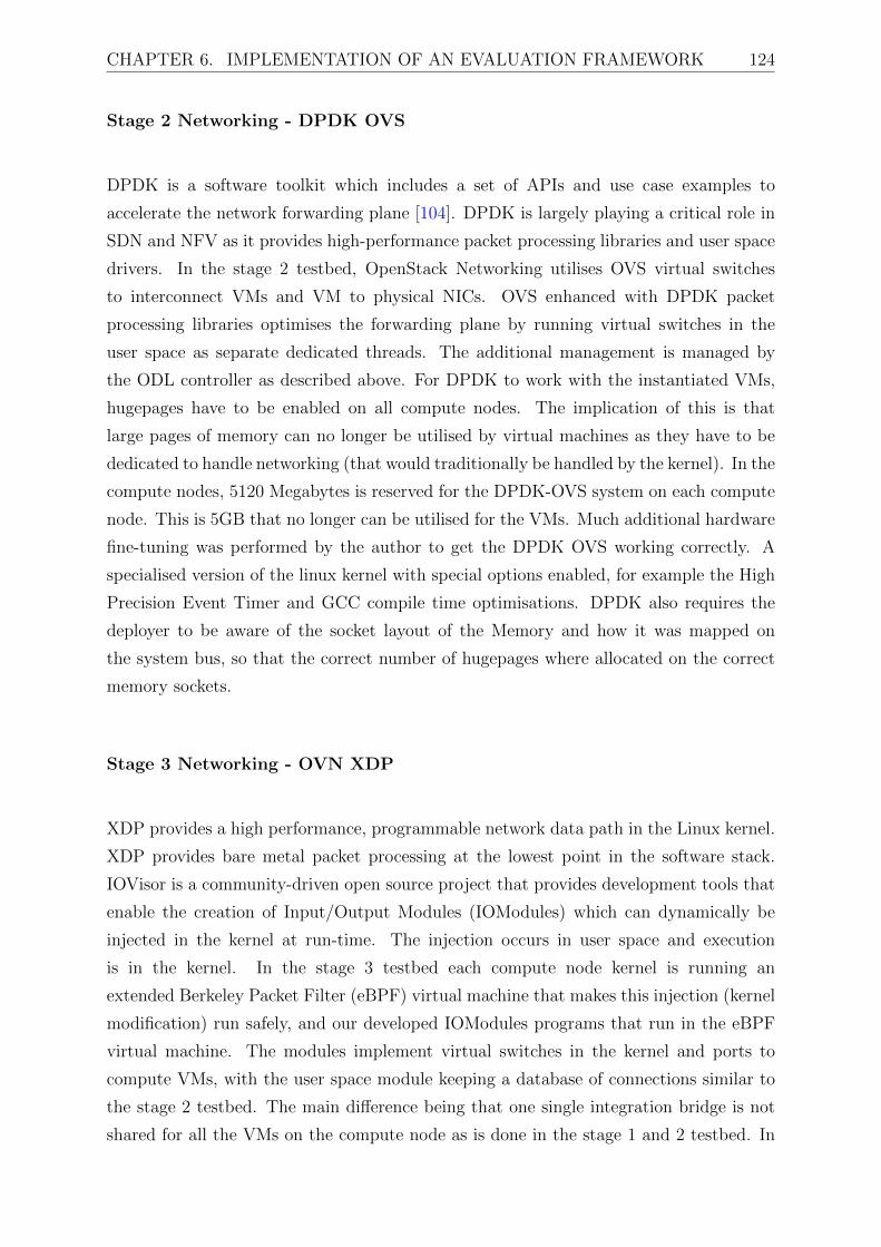
CHAPTER 6. IMPLEMENTATION OF AN EVALUATION FRAMEWORK 124
Stage 2 Networking - DPDK OVS
DPDK is a software toolkit which includes a set of APIs and use case examples to
accelerate the network forwarding plane [104]. DPDK is largely playing a critical role in
SDN and NFV as it provides high-performance packet processing libraries and user space
drivers. In the stage 2 testbed, OpenStack Networking utilises OVS virtual switches
to interconnect VMs and VM to physical NICs. OVS enhanced with DPDK packet
processing libraries optimises the forwarding plane by running virtual switches in the
user space as separate dedicated threads. The additional management is managed by
the ODL controller as described above. For DPDK to work with the instantiated VMs,
hugepages have to be enabled on all compute nodes. The implication of this is that
large pages of memory can no longer be utilised by virtual machines as they have to be
dedicated to handle networking (that would traditionally be handled by the kernel). In the
compute nodes, 5120 Megabytes is reserved for the DPDK-OVS system on each compute
node. This is 5GB that no longer can be utilised for the VMs. Much additional hardware
fine-tuning was performed by the author to get the DPDK OVS working correctly. A
specialised version of the linux kernel with special options enabled, for example the High
Precision Event Timer and GCC compile time optimisations. DPDK also requires the
deployer to be aware of the socket layout of the Memory and how it was mapped on
the system bus, so that the correct number of hugepages where allocated on the correct
memory sockets.
Stage 3 Networking - OVN XDP
XDP provides a high performance, programmable network data path in the Linux kernel.
XDP provides bare metal packet processing at the lowest point in the software stack.
IOVisor is a community-driven open source project that provides development tools that
enable the creation of Input/Output Modules (IOModules) which can dynamically be
injected in the kernel at run-time. The injection occurs in user space and execution
is in the kernel. In the stage 3 testbed each compute node kernel is running an
extended Berkeley Packet Filter (eBPF) virtual machine that makes this injection (kernel
modification) run safely, and our developed IOModules programs that run in the eBPF
virtual machine. The modules implement virtual switches in the kernel and ports to
compute VMs, with the user space module keeping a database of connections similar to
the stage 2 testbed. The main difference being that one single integration bridge is not
shared for all the VMs on the compute node as is done in the stage 1 and 2 testbed. In

CHAPTER 6. IMPLEMENTATION OF AN EVALUATION FRAMEWORK 125
the kernel each interface can be separated by the Linux namespace segregation. We can
create connections between virtual machine interfaces and an IOModule switch directly
by creating virtual Ethernet pairs in their own namespace and connecting the two pairs
to emulate a link between two endpoints. These endpoints can then be attached to the
tap devices of the VM. The subnet of each tenant has a corresponding IOModule.
As mentioned in the previous chapter, the IO Visor project had already implemented
modules that represent a L2 switch and a L3 router. Using these as a basis, the author of
this thesis additionally developed modules to create the tunnel bridge module that could
map different tenant ID information stored in the user space to provide logical separations
in the kernel data path. The L2 switch was reused to implement the integration bridge,
whose function remains identical. A firewall entity is not required as each tenant has
their own integration and tunnel bridges. This setup ensures that VMs belonging to the
same tenant can communicate with each other, but not with VMs of other tenants unless
interconnected by a Layer 3 router.
6.1.5 Hypervisor and Hypervisor bypass
OpenStack supports several hypervisors: KVM, Xen, QEMU, VMWare, Linux containers,
Docker containers and many others. Among other benefits, virtualisation enables IaaS,
enabling users to self-provision virtual machines, essentially creating their own servers
from a user interface or the command line. This makes the cloud management easier to
achieve at a huge disadvantage. The stage one testbed utilises the libvirt KVM hypervisor.
In some cases, such as for high-performance operations, a virtualised environment is
inappropriate, and an actual, physical, bare metal server satisfies the high-performance
requirements. Bare metal provisioning in OpenStack means a customer can use hardware
directly, deploying the workload (image) onto a real physical machine instead of a
virtualised instance on a hypervisor. OpenStack Ironic provisions physical hardware as
opposed to virtual machines [107]. Ironic provides several reference drivers which leverage
common technologies like PXE 2 and IPMI 3, to cover a wide range of hardware. When
compared to the traditional hypervisor functionality (e.g., creating a VM, managing
2The Preboot Execution Environment (PXE) is an industry standard client/server interface thatallows networked computers that are not yet loaded with an operating system to be configured andbooted remotely by an administrator.
3The Intelligent Platform Management Interface (IPMI) is a set of computer interface specificationsfor an autonomous computer subsystem that provides management and monitoring capabilitiesindependently of the host system’s CPU, firmware (BIOS or UEFI) and operating system.
CHAPTER 6. IMPLEMENTATION OF AN EVALUATION FRAMEWORK 126
the power state, and loading an OS onto the VM), Ironic can be thought of as a
lightweight hypervisor API tying together multiple drivers, each of which implement
some portion of that functionality with respect to physical hardware. The author of this
thesis additionally implemented a bare metal acquisition algorithm to match the request
of instantiating a VNF provided by the tenant, with an available preconfigured bare metal
host on the compute nodes.
6.1.6 Monitoring
The testbed collects different types of monitoring information. Facility monitoring
data is used to check if the testbed facilities are currently running by providing
exhaustive data aggregated for status summaries. This data is used by the data centre
administrator (MNO). Infrastructure monitoring is used to collect information relating to
the infrastructure that would be useful for tenants; for example, physical host performance
and resource utilisation. This is provided by the testbed hosts, through the use of a Zabbix
system.
Zabbix is an open source distributed monitoring solution that is used to monitor
selected resources in the data centre network. It utilises a flexible notification mechanism
that allows testbed hosts to configure e-mail based alerts for most events, allowing for
faster identification of any server problems. Zabbix also provides efficient reporting and
data visualisation of stored data. A web based frontend allows for the access to all Zabbix
reports, statistics and configuration parameters.
The key components of the Zabbix:
• Zabbix agents deployed on monitoring targets in order to actively gather
information on local resources (for example memory and processor statistics of
physical and virtual servers) and forwards it to a central Zabbix server for further
processing.
• Zabbix Server is a central process of Zabbix software that monitors, interacts with
Zabbix proxies and agents, calculates triggers, sends notifications and maintains a
central repository of data. The testbed network utilises one central Zabbix server.
In summary, this section described all the components that make up the testbed

CHAPTER 6. IMPLEMENTATION OF AN EVALUATION FRAMEWORK 127
hardware and software. Each component is elaborated on, with descriptions on how
this maps back to the frameworks described in chapter 4 and 5. This is the totality of
the NFV infrastructure that was realised, both developed and integrated, as part of the
thesis. The next sections describe the VNF components that are implemented to run
over the infrastructure that has now been described.
6.2 5G Emulation Tool
The FOKUS OpenEPC platform is a non-open source EPC platform that enables
research, development and testing of protocols and applications on a live testbed.
The OpenEPC is conformant to 3GPP specifications (Release 8). This platform was
chosen because of its high-performance capabilities, adaptability to different deployment
scenarios and configurations.
The Fraunhofer FOKUS OpenEPC toolkit was one of the first to be available
to researchers and vendors for early prototyping and testing of EPC networks.
OpenEPC includes the mechanisms of connecting to different access networks and the
communication interfaces to the various service platforms. The OpenEPC implements
the major functionality detailed by the 3GPP specifications.
The network access layer allows for the connection of the UE to the EPC network.
The access technologies included in the OpenEPC toolkit are 3GPP accesses (LTE,
UMTS, and GPRS), WLAN, WIMAX and Femto cells. These access network technologies
all provide entry points into the core network through specific access network gateways.
The data path is through the SGW for 3GPP access, the ePDG for untrusted non-
3GPP access and a generic Access Network Gateway (ANGw) for trusted non-3GPP
access. Data path terminates in the EPC network always at the PGW out towards the
IP domain (Internet, IMS, or other PDN). The EPC Enablers node provides additional
functionality to the OpenEPC that compliments the core network’s functionality. For
example, the PCRF, IMS, Video Server, and breakout to the internet reside in the EPC
Enablers node.
OpenEPC also allows for network assisted access network discovery and selection
of the different available networks. OpenEPC additionally implements a full network
mobility solution which ensures that service continuity is ensured when End User (EU)

CHAPTER 6. IMPLEMENTATION OF AN EVALUATION FRAMEWORK 128
performs vertical or horizontal handovers. The data and control path through an EPC
network is provided by an EPS bearer. The bearer provides a logical connection between
the UE and the PGW through which IP packets can be transported. The OpenEPC
PCC architecture is central to ensuring that all the necessary entities within the EPC
network are aware of bearer related functions.
The last selling point of the OpenEPC is its ability to integrate with any service
delivery platform which is based on IP connectivity. This could be the public internet,
a private corporate network or an IMS network. The IMS domain consists of nodes
and functions that provide support for multimedia sessions based on Session Initiation
Protocol (SIP) and utilises the IP connectivity provided by the functions in the Packet
Core domain. The EPC could also act as the reliable transport layer for M2M
communications. Figure 6.7 illustrates the components of the OpenEPC
Figure 6.7: OpenEPC component interconnection
The OpenEPC is delivered as software, and it is up to the system user to configure the
various components and ensure that the functions are working as required. This can be
done on physical machines. To enable the OpenEPC software to be virtualised to be run
on OpenStack, the system was installed on Linux server virtual machines over VMware,
which produces a VMDK (VMware) virtual machine format. This was converted to
Qcow2 and could be included on to the OpenStack Image catalogue. Additionally, several
changes needed to be made to both the functionality of OpenStack and the OpenEPC
virtual machines for interworking. For example, when OpenEPC was running on VMware,
it was implemented its own Domain Name System (DNS) server and no DHCP as all
interfaces were statically configure. In OpenStack, we can utilise the DNS mechanisms
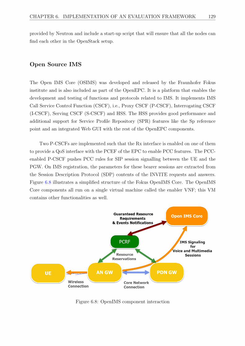
CHAPTER 6. IMPLEMENTATION OF AN EVALUATION FRAMEWORK 129
provided by Neutron and include a start-up script that will ensure that all the nodes can
find each other in the OpenStack setup.
Open Source IMS
The Open IMS Core (OSIMS) was developed and released by the Fraunhofer Fokus
institute and is also included as part of the OpenEPC. It is a platform that enables the
development and testing of functions and protocols related to IMS. It implements IMS
Call Service Control Function (CSCF), i.e., Proxy CSCF (P-CSCF), Interrogating CSCF
(I-CSCF), Serving CSCF (S-CSCF) and HSS. The HSS provides good performance and
additional support for Service Profile Repository (SPR) features like the Sp reference
point and an integrated Web GUI with the rest of the OpenEPC components.
Two P-CSCFs are implemented such that the Rx interface is enabled on one of them
to provide a QoS interface with the PCEF of the EPC to enable PCC features. The PCC-
enabled P-CSCF pushes PCC rules for SIP session signalling between the UE and the
PGW. On IMS registration, the parameters for these bearer sessions are extracted from
the Session Description Protocol (SDP) contents of the INVITE requests and answers.
Figure 6.8 illustrates a simplified structure of the Fokus OpenIMS Core. The OpenIMS
Core components all run on a single virtual machine called the enabler VNF; this VM
contains other functionalities as well.
Figure 6.8: OpenIMS component interaction
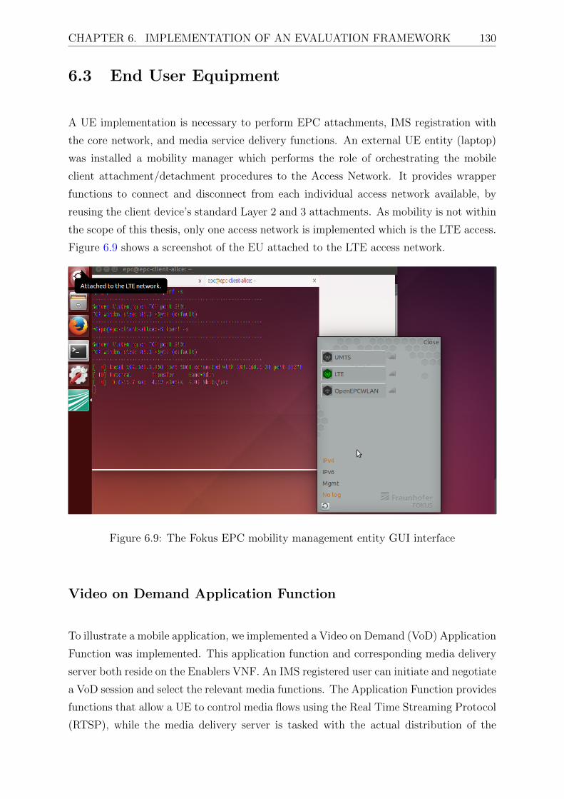
CHAPTER 6. IMPLEMENTATION OF AN EVALUATION FRAMEWORK 130
6.3 End User Equipment
A UE implementation is necessary to perform EPC attachments, IMS registration with
the core network, and media service delivery functions. An external UE entity (laptop)
was installed a mobility manager which performs the role of orchestrating the mobile
client attachment/detachment procedures to the Access Network. It provides wrapper
functions to connect and disconnect from each individual access network available, by
reusing the client device’s standard Layer 2 and 3 attachments. As mobility is not within
the scope of this thesis, only one access network is implemented which is the LTE access.
Figure 6.9 shows a screenshot of the EU attached to the LTE access network.
Figure 6.9: The Fokus EPC mobility management entity GUI interface
Video on Demand Application Function
To illustrate a mobile application, we implemented a Video on Demand (VoD) Application
Function was implemented. This application function and corresponding media delivery
server both reside on the Enablers VNF. An IMS registered user can initiate and negotiate
a VoD session and select the relevant media functions. The Application Function provides
functions that allow a UE to control media flows using the Real Time Streaming Protocol
(RTSP), while the media delivery server is tasked with the actual distribution of the

CHAPTER 6. IMPLEMENTATION OF AN EVALUATION FRAMEWORK 131
media. Media resources are hosted on a Video LAN Codec (VLC) RTSP server that
listens for incoming requests on port 5554. The requests are received directly from IMS
clients as URLs of the form:
rtsp://ims.openepc.net:5554/Test
Figure 6.10 illustrates an ongoing video session on the UE.
Figure 6.10: Video on Demand application service on the EU
6.4 Summary
This chapter has detailed the components necessary to create a fully functional NFVI
testbed. The testbed comprises elements in the infrastructure management, physical and
virtualised resources, cloud application use cases and end user equipment. All developed
elements exhibit strict conformance to relevant ETSI and 3GPP standards. This is critical
to ensure that when the testbed is evaluated, the results are an accurate representation of

CHAPTER 6. IMPLEMENTATION OF AN EVALUATION FRAMEWORK 132
a realistic mobile network and NFV deployment. The framework is a true open testbed
and comprises entirely Free and Open Source software. This exposes the complex concepts
to a wide range of developers and helps accelerate technology acceptance.
It also provides a convenient point of departure for further research in the field,
as evaluations are for the most part reproducible in the practical environment and
the components can be easily and legally extended to incorporate future experimental
technologies. The exception of this is the OpenEPC software which is under a license.
The contributions made directly by the author can be summarised as follows:
• The stage 1 testbed required the compilation of the EPC function software and
creation of startup scripts that that would on-board the sofware components when
instantiated. The various internal EPC components (for example the mme, enodeb,
pcrf, ims, pgw, dns etc.) could not resolve each other as it is not known a priori what
IP addresses VNFs would receive from the openstack networking service. This led
to the author developing start up scripts on each image for the software components
to resolve each other’s IP addresses in the OpenStack environment
• The stage 2 testbed required specialised kernel compilation and hardware finetuning
that was specific to the compute machines that housed the deployed VNFs.
• The stage 3 testbed required the compilation of a specialised kernel that allowed
for the installation of BCC tools, and also the development of the IOModules
• Integration work was required to enable OpenStack Ironic service and conductor
to work with the EPC VNF images created (i.e. creation of initramfs and vmlinuz
images)
• The compilation of the EPC User Equipment software required the removal of the
generic linux networking manager and replaced with the EPC mobility management
entity.
• The creation of a video streaming server for the illustration of a Video on Demand
Application Function hosted in the IMS application domain.
The testbed implementation demonstrates proof of concept, the next chapter details
extensive evaluations of the proposed concepts. The framework provides a practical
environment where the performance and reliability of the experimental mechanisms can
be studied.

Chapter 7
Performance Evaluation
The design and practical implementation of the shared infrastructure management
framework and the performance enhanced frameworks were detailed in the previous
chapters. While the evaluation framework demonstrates proof of concept, the framework
needs to be further subjected to realistic evaluations to determine the suitability and
viability of the proposed solutions. A network simulation environment would not be
able to adequately represent the various intricacies of a realistic environment and thus a
practical testbed implementation was developed to provide realistic measurements.
In this chapter, the proposed architectures of the shared infrastructure management
framework and the performance enhanced framework are incorporated incrementally into
the testbed and evaluated. Additionally, the vEPC and Virtualised IMS (vIMS) use cases
are utilised as the IaaS applications provided and are evaluated.
The performance metrics that are important to this investigation are those that
relate to the NFV Infrastructure (NFVI) whose management and orchestration functions
directly impact service quality delivered by VNF instances hosted on NFVI. These service
quality metrics cover both direct service impairments, such as IP packet lost by VNF
virtual networking infrastructure which impacts end user service latency or quality of
experience, and indirect service quality risks, such as NFV management and orchestration
failing to continuously and rigorously enforce predefined rules (such as launching a bare
metal VNF on a VM that meets minimum resource criteria) which increase the risks of
an infrastructure failure or causing unacceptable VNF end user services.
The final validation is done to determine if the developed solutions have met the
133

CHAPTER 7. PERFORMANCE EVALUATION 134
design requirements developed in chapters 4 and 5. These will determine whether the
implementation fulfils both high-level requirements and functionality specific goals that
were set.
The results of evaluations performed aim to demonstrate the effectiveness of the
proposed solution, particularly regarding the introduction of virtualisation and its effect
on end user perceived service quality. Moreover, they show some limitations of the
deployment and provide some insights for future work. Every effort has been made
to ensure full reproducibility of all testing procedures through the use of open source
software and open testbed toolkits.
7.1 Introduction
According to [108], end users experience services delivered by VNF instances which can
be interconnected and resulting VNF components working together in what is referred to
as service chaining. The services delivered to end users by individual VNF instances are
dependent on the service quality of the virtual machine instance that hosts the component
and the virtual network service that delivers connectivity to the VNFs.
7.1.1 Evaluation Metrics
VNF provisioning latency directly impacts the time it takes to elastically grow online
VNF service capacity or to restore full VNF redundancy following a failure event. VNF
termination latency and reliability is the time it takes to release resources that are no
longer in use by the tenant. This also impacts the time from when a tenant is no longer
authorised to utilise resources to when said resources are no longer available to the tenant
(for example if the tenant has not paid a bill to utilise further resources).
Packet delay characterises user service latency introduced by communications
between a VNF in the service chain, which impacts the service latency and quality of
service enjoyed by end users. Packet delay variation (jitter) is a derived metric that
characterises the incremental user service delay variation introduced by instability in
communications latency between VNFs, which impacts the service latency and quality of
service enjoyed by end users.

CHAPTER 7. PERFORMANCE EVALUATION 135
Delivered throughput is a derived metric from the offered load input parameter
and other packet transfer performance metrics (loss, delay) measured at that load to
characterise the actual capacity of communications between VNFs. Packet loss ratio
impacts end user service latency and quality because lost packets could be detected, and
mitigated via retry, retransmission or concealment by higher layer functions, which would
impact the service latency and quality of service enjoyed by end users.
VN slice provisioning latency and reliability directly contribute to the time needed to
create or add VN service capacity, or to restore full VN redundancy. These metrics track
the time to successfully establish network infrastructure connectivity when requested,
and the establishment attempts that fail, respectively.
The end user service quality of VNFs that rely on technology components offered as-
a-service is directly impacted by the type of service under investigation. We investigate
the service quality metrics pertinent to vEPC and vIMS functionality. For example, the
service quality experienced by an end user is bearer plane functionality and management,
in the vEPC use case, and session initiation signalling in the vIMS use case.
7.1.2 Evaluation Scenarios
The performance of individual components and procedures can be better analysed if
the proposed changes are incorporated into the testbed in stages and evaluated at each
increment; hence three scenarios are introduced for the test procedures. The first scenario
is the shared infrastructure management framework as described and implemented in
Chapter 4. This scenario has traditional hypervisor virtualisation and native virtual
switching. The second scenario is the performance enhanced management framework as
described and implemented in Chapter 5. This scenario has bare metal virtualisation with
user space virtual switching. The third scenario is the performance enhance management
framework as described and implemented in Chapter 5. This scenario has bare metal
virtualisation with kernel space virtual switching.

CHAPTER 7. PERFORMANCE EVALUATION 136
7.2 VNF Service Quality Metrics
Figure 7.1 visualises the lifecycle as a state diagram of a single VM instance. The lifecycle
begins with a request to the NFV management and orchestration domain to allocate a
new VM instance to startup, grow or repair VM capacity. The response to that request is
either a newly allocated VNF instance or a failure response (e.g. resources unavailable).
The newly allocated VM instance is then integrated with the VNF. Integration of the
newly allocated VM with the VNF instance can either be successful in which case the
new VM instance begins serving VNF users at this time or the integration fails, such
as because the allocated VM instance was inoperable or ”dead-on-arrival”. The VM
instance’s useful life begins when it is available to serve VNF users. The useful life ends
either with an orderly release when the application domain gracefully releases the VM
instance via the management and orchestration domain (e.g. to elastically shrink VM
capacity); alternately, the VM can be prematurely released due to failure or for other
reasons (e.g. executing a lawful takedown order or non-payment of bill). The VNF
evaluation methodologies set out in the following section are adopted from the ETSI
pre-deployment testing of NFV Environments and Services [109].
VNF Launch
pending
running
shutting-down
terminated
stopping stoppedrebootingreboot
terminate
stop
start
terminate
Tstart
Tstop
Figure 7.1: VM Lifecycle Management
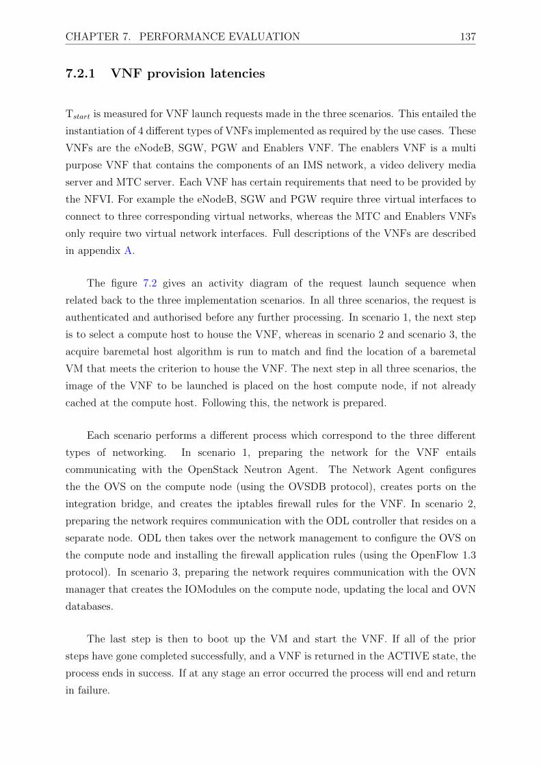
CHAPTER 7. PERFORMANCE EVALUATION 137
7.2.1 VNF provision latencies
Tstart is measured for VNF launch requests made in the three scenarios. This entailed the
instantiation of 4 different types of VNFs implemented as required by the use cases. These
VNFs are the eNodeB, SGW, PGW and Enablers VNF. The enablers VNF is a multi
purpose VNF that contains the components of an IMS network, a video delivery media
server and MTC server. Each VNF has certain requirements that need to be provided by
the NFVI. For example the eNodeB, SGW and PGW require three virtual interfaces to
connect to three corresponding virtual networks, whereas the MTC and Enablers VNFs
only require two virtual network interfaces. Full descriptions of the VNFs are described
in appendix A.
The figure 7.2 gives an activity diagram of the request launch sequence when
related back to the three implementation scenarios. In all three scenarios, the request is
authenticated and authorised before any further processing. In scenario 1, the next step
is to select a compute host to house the VNF, whereas in scenario 2 and scenario 3, the
acquire baremetal host algorithm is run to match and find the location of a baremetal
VM that meets the criterion to house the VNF. The next step in all three scenarios, the
image of the VNF to be launched is placed on the host compute node, if not already
cached at the compute host. Following this, the network is prepared.
Each scenario performs a different process which correspond to the three different
types of networking. In scenario 1, preparing the network for the VNF entails
communicating with the OpenStack Neutron Agent. The Network Agent configures
the the OVS on the compute node (using the OVSDB protocol), creates ports on the
integration bridge, and creates the iptables firewall rules for the VNF. In scenario 2,
preparing the network requires communication with the ODL controller that resides on a
separate node. ODL then takes over the network management to configure the OVS on
the compute node and installing the firewall application rules (using the OpenFlow 1.3
protocol). In scenario 3, preparing the network requires communication with the OVN
manager that creates the IOModules on the compute node, updating the local and OVN
databases.
The last step is then to boot up the VM and start the VNF. If all of the prior
steps have gone completed successfully, and a VNF is returned in the ACTIVE state, the
process ends in success. If at any stage an error occurred the process will end and return
in failure.

CHAPTER 7. PERFORMANCE EVALUATION 138
Figure 7.2: VNF provision activity diagram.
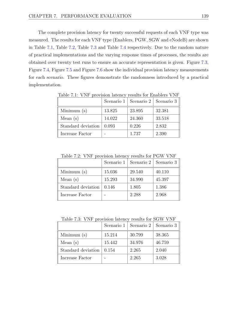
CHAPTER 7. PERFORMANCE EVALUATION 139
The complete provision latency for twenty successful requests of each VNF type was
measured. The results for each VNF type (Enablers, PGW, SGW and eNodeB) are shown
in Table 7.1, Table 7.2, Table 7.3 and Table 7.4 respectively. Due to the random nature
of practical implementations and the varying response times of processes, the results are
obtained over twenty test runs to ensure an accurate representation is given. Figure 7.3,
Figure 7.4, Figure 7.5 and Figure 7.6 show the individual provision latency measurements
for each scenario. These figures demonstrate the randomness introduced by a practical
implementation.
Table 7.1: VNF provision latency results for Enablers VNF
Scenario 1 Scenario 2 Scenario 3
Minimum (s) 13.825 23.895 32.381
Mean (s) 14.022 24.360 33.518
Standard deviation 0.093 0.226 2.832
Increase Factor - 1.737 2.390
Table 7.2: VNF provision latency results for PGW VNF
Scenario 1 Scenario 2 Scenario 3
Minimum (s) 15.036 29.540 40.110
Mean (s) 15.293 34.990 45.397
Standard deviation 0.146 1.805 1.386
Increase Factor - 2.288 2.968
Table 7.3: VNF provision latency results for SGW VNF
Scenario 1 Scenario 2 Scenario 3
Minimum (s) 15.214 30.799 38.365
Mean (s) 15.442 34.976 46.759
Standard deviation 0.154 2.265 2.040
Increase Factor - 2.265 3.028

CHAPTER 7. PERFORMANCE EVALUATION 140
Table 7.4: VNF provision latency results for eNodeB VNF
Scenario 1 Scenario 2 Scenario 3
Minimum (s) 15.130 29.260 31.036
Mean (s) 15.289 33.150 40.708
Standard deviation 0.111 2.784 3.635
Increase Factor - 2.168 2.663
Figure 7.3: Enablers provisioning Figure 7.4: PGW provisioning
Figure 7.5: SGW provisioning Figure 7.6: eNodeB provisioning
Discussion
When comparing within the same scenarios the performance of VNFs in contrast to
each other, the enablers VNF incurs the lowest average provision delay compared to the
other VNFs. This is directly attributed to the fact that this VNF only requires two
network connections (three if you include the management network) whereas the other
VNFs require three network connections (four if you include the management network)
as shown in appendix A. The preparation of a port to attach to the instantiated VM thus
takes a significant amount of time and noticeably impacts the provision latency of VNFs.

CHAPTER 7. PERFORMANCE EVALUATION 141
The results show that for all VNF provision latencies, incorporating the stage 2 and
stage 3 testbed enhancements increases the delay by a small factor. For the Enablers,
PGW, SGW, and eNodeB VNFs scenario 2 takes on average 1.74, 2.89, 2.27 and 2.17
times longer to provision respectively if scenario 1 is used as the reference case. Similarly
for scenario 3 it takes on average 2.4, 2.97, 3.03 and 2.66 times longer to provision.
In scenario 2, the provision workflow interaction requires communication with the
ODL controller which introduces a delay. In scenario 3, the update of the local and
external network databases introduce this delay. In scenario 2 and 3 the need to find and
allocate an appropriate bare metal host introduces further delays that are not inherent
to scenario 1 where bare metal virtualisation is not used.
In looking for other work to compare these results to, it is difficult to find
measurements that have been defined in standards, or reported in proof of concepts.
However in March of 2017, ETSI completed their first NFV Plugtests where similar tests
were performed [110, 111]. No results provide exact numbers, however, proof of concept
solutions could report if such a test was successfully completed within a 180 minute test
case duration. All our tests come in under less than a minute which we deem to be
acceptable.
7.2.2 VNF termination latencies
Tstop is measured for VNF termination requests made in the three scenarios. This entailed
the termination of the 4 different types of VNFs implemented as required by the use cases.
The figure 7.7 gives an activity diagram of the termination request sequence.

CHAPTER 7. PERFORMANCE EVALUATION 142
Figure 7.7: VNF termination activity diagrams
In all three scenarios, the request is authenticated and authorised before any further
processing. In scenario 1, the hypervisor service initiates a shutdown, whereas in scenarios
2 and 3, the bare metal service has to further release the bare metal host resources
and update the bare metal host database. Next, each scenario performs a different
process which matched to the 3 types of networking. Scenario 1 deletes ports, scenario

CHAPTER 7. PERFORMANCE EVALUATION 143
2 additionally informs the ODL controller, and scenario 3 additionally deletes the local
and external database entries mapped to the VNF. Again, if all of the prior steps have
completed successfully the process ends in success. If at any stage an error occurred
the process will end and return in failure. The complete termination latency for twenty
successful requests of each VNF type was measured. The results for each VNF types
(Enablers, PGW, SGW and eNodeB) are shown in Table 7.5, Table 7.6, Table 7.7 and
Table 7.8 respectively. Figure 7.8, Figure 7.9, Figure 7.10 and Figure 7.11 show the
individual termination latency measurements for each scenario.
Table 7.5: VNF termination latency results for Enablers
Scenario 1 Scenario 2 Scenario 3
Minimum (s) 1.959 8.100 11.061
Mean (s) 2.128 8.686 11.354
Standard deviation 0.079 0.280 0.268
Increase Factor - 4.082 5.336
Table 7.6: VNF termination latency results for PGW
Scenario 1 Scenario 2 Scenario 3
Minimum (s) 2.488 9.643 13.689
Mean (s) 2.674 10.200 14.200
Standard deviation 0.112 0.251 0.390
Increase Factor - 3.814 5.310
Table 7.7: VNF termination latency results for SGW
Scenario 1 Scenario 2 Scenario 3
Minimum (s) 2.589 10.295 14.289
Mean (s) 2.748 10.710 14.894
Standard deviation 0.087 0.243 0.311
Increase Factor - 3.898 5.421
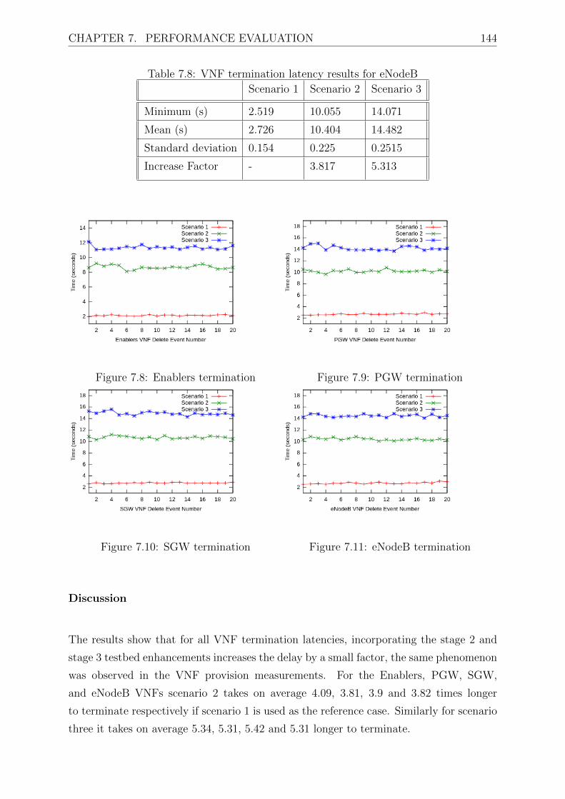
CHAPTER 7. PERFORMANCE EVALUATION 144
Table 7.8: VNF termination latency results for eNodeB
Scenario 1 Scenario 2 Scenario 3
Minimum (s) 2.519 10.055 14.071
Mean (s) 2.726 10.404 14.482
Standard deviation 0.154 0.225 0.2515
Increase Factor - 3.817 5.313
Figure 7.8: Enablers termination Figure 7.9: PGW termination
Figure 7.10: SGW termination Figure 7.11: eNodeB termination
Discussion
The results show that for all VNF termination latencies, incorporating the stage 2 and
stage 3 testbed enhancements increases the delay by a small factor, the same phenomenon
was observed in the VNF provision measurements. For the Enablers, PGW, SGW,
and eNodeB VNFs scenario 2 takes on average 4.09, 3.81, 3.9 and 3.82 times longer
to terminate respectively if scenario 1 is used as the reference case. Similarly for scenario
three it takes on average 5.34, 5.31, 5.42 and 5.31 longer to terminate.

CHAPTER 7. PERFORMANCE EVALUATION 145
If we compare in the same scenarios the performance of VNFs in contrast to each
other, the enablers VNF incurs again the lowest average termination delay compared to
the other VNFs. Again, since this VNF has less connections to the VN, it results in less
time for the termination to complete. Termination requests overall take much less time to
complete compared to provision requests. Of all measurements taken, none takes longer
than 17 seconds.
7.3 Virtual Network Slice Service Quality Metrics
Similary to VNFs, VNs undergo a lifecycle management. However this lifecycle is much
less complex as the VN can be in an instantiated state or terminated state. VNFs will
utilise the VN to send and received traffic between themselves and with external end
users. The virtual network service quality metrics measured in our evaluation are [41]:
• The time it takes to bring a VN online, this is also known as the VN instantiation
time. This is useful for the NFVI user as they can plan how long it takes bring the
network services online, or how long it takes to scale network services.
• The time it takes to takedown a VN, this is known as the VN termination. This is
useful as it indicates how long VN resources can be released during periods when
they are no longer needed.
• Of the total packets send from an entry point on the VN (i.e., originating from a
VNF, or from the end user into the VN), packet loss is the rate of packets that are
either never delivered to the destination or delivered to the destination after the
VNF’s maximum acceptable packet delay budget.
• Packet delay is the elapsed time from an entry point on the VN to its destination
VNF. Packets that are delivered with more than the VNF’s maximum acceptable
packet delay are counted as packet loss events and excluded from packet delay
measurements and included to the packet loss capture.
• Packet delay variance (a.k.a. jitter) is the variance in packet delay. This metric can
impact the end user service quality depending on the service being utilised.

CHAPTER 7. PERFORMANCE EVALUATION 146
7.3.1 VN resources provision and termination latencies
The VN provision and termination latencies are measured. These entail the preparation
of the relevant matchings for the creation of or deletion of virtual network mappings.
Due to the random nature of the testbed, 100 provision and termination events were
captured to analyse. The figure 7.12 gives an activity diagram of the request launch
sequence. The main differences in the three scenarios is the prepare network function.
Each scenario involved the interaction with the network controller which provides the
networking services. In scenario 1 this is the Neutron Agent, in scenario 2 this is the
ODL controller residing on a separate machine, and in scenario 3 this is the update of
the local and external databases.
Figure 7.12: VN provision/termination activity diagrams
The provision latencies for one hundred successful requests of VNs were measured.

CHAPTER 7. PERFORMANCE EVALUATION 147
The results are shown in Table 7.9 and Figure 7.13. Similarly, the termination latencies
for one hundred successful request of VNs were measured. The results are shown in Table
7.10 and Figure 7.14.
Figure 7.13: 100 VN provision events
Table 7.9: VN provision latency results
Scenario 1 Scenario 2 Scenario 3
Minimum (s) 1.132 4.116 5.74
Mean (s) 1.178 4.515 6.040
Standard deviation 0.0273 0.258 0.152
Increase Factor - 3.834 5.130
Figure 7.14: 100 VN termination results

CHAPTER 7. PERFORMANCE EVALUATION 148
Table 7.10: VN termination latency results
Scenario 1 Scenario 2 Scenario 3
Minimum (s) 0.515 2.652 3.65
Mean (s) 0.563 3.045 3.967
Standard deviation 0.0413 0.294 0.127
Increase Factor - 5.405 7.041
Discussion
Similar to the VNF provision and termination test cases, VN provision and termination
latencies are increased for scenario 2 and even more for scenario three when compared to
scenario 1. This can be attributed to the additional interaction required from these two
scenarios. Comparably the times observed of these events are within the same order of
magnitude.
What is interesting is that there is much higher deviation on measured results for
scenario 2 compared to scenario 3. All test cases completed under 7 seconds for provision
and 4 seconds for termination.
7.3.2 Network Slice Throughput Performance
Tests were run to evaluate the performance of network slices when they interact with each
other. As the main focus of this thesis is the enabling of multi-tenant 5G infrastructure
sharing, we consider a network slice to be a grouping of virtual and physical resources
which act as a sub-network owned by a single tenant. In this case we initialise one slice,
measure its performance in the three scenarios, add another slice and measure, up till
4 slices have been instantiated. Each slice belongs to a different tenant. Figure 7.15
and 7.16 illustrate the testing setup for the following investigations. Each network slice
consists of two interconnect generic VNFs that communication of one VN.

CHAPTER 7. PERFORMANCE EVALUATION 149
VM VM
Native OVS
PORT PORT
VM VM
OVS with DPDK
PORT PORT
VM VM
XDP
PORT PORT
Figure 7.15: Network slice makeup for the 3 scenarios
switch
VM VM
VM
VM
VM
VM
VMVM
Figure 7.16: 4 network slices regardless of the scenario
All tests are uni-directional for east-west traffic across two VMs. Test durations (per
packet size) were 60 seconds. As per RFC 2544 [112], which outlines the benchmarking
methodology for network interconnect devices, relevant performance metrics are latency,
frame loss percentage, and maximum data throughput varied across different packet sizes.
Figure 7.17 and Figure 7.18 show the sending statistics for the network generator and
network receiver respectively when one slice is running. Figure 7.19 and Figure 7.20 show
the sending statistics for the network generator and network receiver respectively when

CHAPTER 7. PERFORMANCE EVALUATION 150
two slices are running. Figure 7.21 and Figure 7.22 show the sending statistics for the
network generator and network receiver respectively when three slices are running. And
finally, Figure 7.19 and Figure 7.20 show the sending statistics for the network generator
and network receiver respectively when four slices are running. They are placed side by
side to highlight and compare statistics.
Figure 7.17: 1 network slice: send stats Figure 7.18: 1 network slice recv stats
Figure 7.19: 2 network slices send stats Figure 7.20: 2 network slices: recv stats
Figure 7.21: 3 network slices: send stats Figure 7.22: 3 network slices: recv stats

CHAPTER 7. PERFORMANCE EVALUATION 151
Figure 7.23: 4 network slices: send stats Figure 7.24: 4 network slices: recv stats
Discussion
Figure 7.17 shows scenario 2 greatly outperforming both scenario 1 and scenario 3.
Performance is then followed by scenario 3 with scenario 1 achieving the lowest maximum
packets per second rate of the three scenarios. This shows the DPDK is able to generate
packets for transmission at a high rate from the sending side of the VNF. Figure 7.18
shows the packet rate effectively measured at the receive VNF. This shows that the
performance of scenario 2 slightly outperforms scenario 3 for all frame size except for
the last test case of 1518 size packets when performance drastically diminishes. Scenario
1 still performs the worst except for 1518 packet size. When only one slice is running,
limiting the Ethernet frame size to 64 bytes utilising scenario 2 will result in the best
performance.
It should be noted that the scale of the figures changes as the number of slices
increases. Figure 7.19 shows that when 2 slices are operating, scenario 2 is still resulting
in the highest rate of packet generates from the VNF sender. Comparably scenario
3 is second best with scenario 1 being the worst. This is completely reversed at the
receive VNF as shown in Figure 7.20. Here scenario 3 results in the best performance
for all packet sizes with scenario 1 performing the second best. Scenario 2 has the worst
performance. When two slices are running, limiting the Ethernet frame size to 64 bytes
utilising scenario 3 will result in the best performance.
Figure 7.21 and Figure 7.23 show similar performance results for the 3 and 4 slice
sending statistics. In the 4 slice scenario, some packet sizes (64, 128, 256) result in scenario
3 performing better, however the rest of the test cases scenario 2 performs better at the
sending side. Figure 7.22 and Figure 7.24 have scenarios 1 and 3 performing almost

CHAPTER 7. PERFORMANCE EVALUATION 152
similarly. However, for each 3 and 4 slices, limiting the Ethernet frame size to 64 bytes
utilising scenario 3 will result in the best performance.
All of these tests were performed on 10 Gbps software switches. Assuming no errors
in transmission the theoretical maximum packets per second achievable (assuming small
packets) is 1.4 Mpps. DPDK-OVS achieves the highest sending rates (at about 0.6 Mpps)
because it is operating purely in user space in sections of memory that is isolated to only
packet handling. Obviously as the number of slices increase, each slice is sharing the same
resource as other slices hence this sending rate (which is representative on an individual
slice) reduces. Pure OVS can not reach anywhere this theoretical maximum because pure
OVS is operated both in user and kernel space, and resources are shared with other OS
and user operations While DPDK-OVS is prone to high data sending rates, it is also
susceptible to high error rates. This is further investigated in the next subsection
7.3.3 Network Slice Packet Loss
The previous test cases showed that while high data rates were being achieved at the
sending side, the receive side of the test case always resulted in a reduced effective
throughput. This implicates packet loss in the network. The following test cases
aim to measure and quantify the packet loss for the 3 scenarios in the different slice
configurations. The error is measured as the number of packets successful generated as a
fraction of the number of packets successfully received. Figure 7.25, Figure 7.26, Figure
7.27 and Figure 7.28 show the error rates for the previous test cases, as a measure of the
fraction of packets lost ranging from 0 (no packets lost) to 1 (all packets lost).
Figure 7.25: 1 slice: effective error rate Figure 7.26: 2 slices: effective error rate

CHAPTER 7. PERFORMANCE EVALUATION 153
Figure 7.27: 3 slices: effective error rate Figure 7.28: 4 slices: effective error rate
Discussion
For all scenarios under all network slice experiments, scenario 1 achieves the least number
of dropped or lost packets. Scenario 2 achieves the highest number dropped or lost
packets. Interesting enough, for one slice, when the best performing scenario is scenario
2, it is also the worst performing in terms of packets lost. Another interesting observation
is that for scenarios 2 and 3, the packet loss trend is increasing until 256 bytes and will
start to slightly decrease, especially at the 768 bytes tests and then trend back up.
Throughout network slice evaluations, it was observed that scenario 2 has the
potential to be the most performant setup except for the fact that this scenario
experienced significant packet loss ratio which ends up affecting the observed throughput
for any connection in this scenario. The author attributes this to the technical
functionality of the DPDK-OVS networking implementation that requires dedicated pools
of memory and CPU utilisation to complete its processes. If these resources are also
shared with other functions, for example the OS and other applications, degradation
is expected. A workaround to this would be to have a dedicated network processing
unit that would offload networking workloads from the system. This is corroborated by
measuring the CPU and memory load of a single compute node in each scenario while
it services tenants for one hour. This is shown in Figure 7.29 and Figure 7.30. The least
resource intensive is scenario 1, followed by scenario 3, with scenario 2 being the most
computationally intensive.

CHAPTER 7. PERFORMANCE EVALUATION 154
Figure 7.29: Compute node CPU load
Figure 7.30: Compute node memory utilisation
7.3.4 Network Slice Protocol Comparisons
Up until this point, the test cases where done using UDP as the transport layer protocol
to enable the maximum throughput possible. In data centres, it is likely that TCP will
be utilised by some applications and hence the following tests aim to provide insight on
how TCP performs in the 3 scenarios and with the different number of network slices.
Figure 7.31 show the performance of TCP connections for all scenarios for the 4
number of network slices running. In all test cases, scenario 2 performs the worst. For 1
and 2 slices, scenario 3 performs the best, while for 3 and 4 slices scenario 1 performance
the best. This is expected as TCP a protocol that is performs better when there is low

CHAPTER 7. PERFORMANCE EVALUATION 155
rates of packet loss, and as the previous test cases show scenario 2 experiences the highest
packet loss rates.
Figure 7.32 shows the average end to end latency of transactions as run over TCP
and UDP. The results here show that scenario 2 achieves the lowest latency of the three
scenarios for TCP and UDP traffic. Scenario 3 achieves the second best performance, with
scenario 1 results in the highest end to end latencies for both TCP and UDP transactions.
Figure 7.31: Throughput in TCP
Figure 7.32: Throughput on constant packet size in TCP and UDP
7.4 Technology specific components quality metric
In this thesis, Infrastructure-as-a-service is offered to NFVI customers so that they can
deploy vEPCs, vIMS, and other network services. The cloud provider offers a library of
templates that a tenant can utilise to build and manage their own virtual networks. The

CHAPTER 7. PERFORMANCE EVALUATION 156
core technology component as-a-service (TcaaS) quality metrics are related to vEPC,
vIMS and other functionality. These can be defined as:
• Network attach time: the time it takes to get a connection from the mobile network
(i.e. an IP address and default bearer).
• Session initiation delays: the time it takes to get a Guarenteed Bit Rate (GBR)
bearer for a service initiation and from when the first packets are received on this
bearer.
• Bearer characteristics for GBR bearers
– Achieved data throughput
– Packet delay
– Packet delay variation
– Packet loss ratio
The fundamental task of an EPC is to provide IP connectivity to terminals for
voice and data services to end users. For this the user requires a subscription to the
EPS/LTE network and the operator keeps track of users who are allowed to utilise
their network. Each tenant maintains this information in their HSS, and the user can
authenticate themselves with their user equipment. The user equipment triggers the
process of attaching and connecting to the network. During this process the eNodeB,
MME, HSS, SGW and PGW exchange a range of messages and create the appropriate
links among each other to offer an IP address to the user equipment and a default bearer
to serve the end user. This process is extensively illustrated in Figure 7.33. Figure 7.34
shows a screenshot of a tenant vEPC and vIMS on the Horizon dashboard.
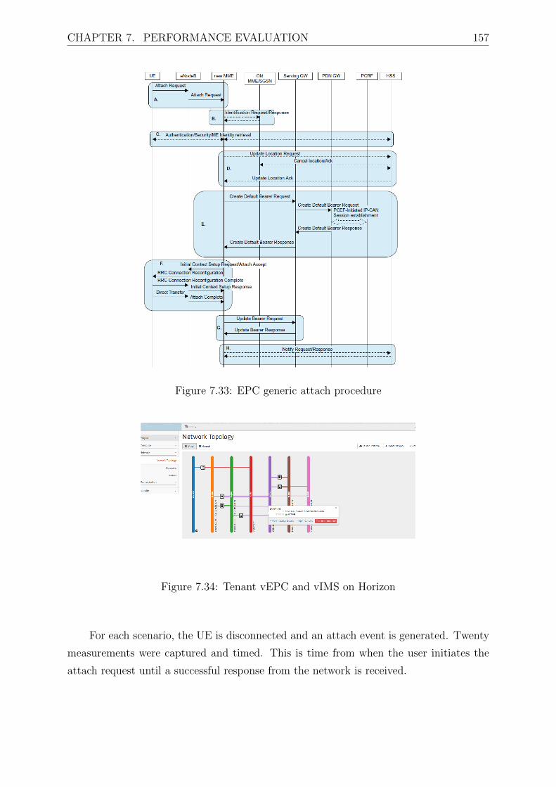
CHAPTER 7. PERFORMANCE EVALUATION 157
Figure 7.33: EPC generic attach procedure
Figure 7.34: Tenant vEPC and vIMS on Horizon
For each scenario, the UE is disconnected and an attach event is generated. Twenty
measurements were captured and timed. This is time from when the user initiates the
attach request until a successful response from the network is received.

CHAPTER 7. PERFORMANCE EVALUATION 158
Figure 7.35: EPC attach latency measurements
Table 7.11: Network attach latency results
Scenario 1 Scenario 2 Scenario 3
Minimum (ms) 3.0 0.8 2.1
Mean (ms) 5.0 1.2 3.2
Standard deviation 1.7 0.2 1.1
Factor decrease - 0.24 0.63
The next set of tests investigate the performance of the connection the UE
experiences on the establish connectivity context. For each test twenty measurement
events were run results captured. Table 7.12 gives the results on the session establishment
times. This is a measure from when the UE attempts to start an IMS multimedia service
i.e. establishment of a GBR bearer until the final request response is received. Table 7.13
gives the end to end latency observed on the established GBR bearer. Table 7.14 gives
the end to end packet delay variation observed on the established GBR bearer. Table
7.15 gives the loss ratio for each measurement event. And finally, Table 7.16 gives the
effective throughput for a GBR bearer that promises 100Mbps.
Table 7.12: Session initiation setup delays
Scenario 1 Scenario 2 Scenario 3
Minimum (ms) 0.631 0.224 0.491
Mean (ms) 0.681 0.225 0.542
Maximum (ms) 0.722 0.226 0.572

CHAPTER 7. PERFORMANCE EVALUATION 159
Table 7.13: GBR connection latency
Scenario 1 Scenario 2 Scenario 3
Minimum (ms) 0.868 0.468 1.000
Mean (ms) 1.687 0.550 1.641
Maximum (ms) 2.516 0.636 2.656
Table 7.14: Packet delay variation
Scenario 1 Scenario 2 Scenario 3
Minimum (ms) 0.007 0.001 0.001
Mean (ms) 0.066 0.001 0.003
Maximum(ms) 0.212 0.004 0.010
Table 7.15: Packet loss ratioScenario 1 Scenario 2 Scenario 3
Minimum (%) 0.000 0.000 0.000
Mean (%) 0.005 0.016 0.000
Maximum (%) 0.100 0.310 0.000
Table 7.16: Connection throughput
Scenario 1 Scenario 2 Scenario 3
Minimum (Mbps) 99.3 99.4 99.5
Mean (Mbps) 99.67 99.69 99.69
Maximum (Mbps) 100 99.7 99.8
Discussion
To evaluate these measurements we compare against the 3GPP standardised Quality of
Service Class Identifier characteristics [6]. Conversational voice requires a 100ms delay
budget with packet loss ratio to remain within 0.1%. Real time gaming requires a 50ms
delay budget with packet loss ratio to remain within 10−3 %. Conversational video or

CHAPTER 7. PERFORMANCE EVALUATION 160
live streaming requires a 150ms delay budget with 0.1% packet loss ratio. IMS signalling
and video streaming have a delay budget of 100ms and 10−3 % packet loss ratio.
When it comes to the delay budgets scenario 1 and scenario 3 can fulfil the
requirements for conversational video or live streaming only. Scenario 2 can fulfil the
requirements for conversational voice, conversational video, live streaming, IMS signalling
and video streaming. When it comes to packet loss ratio scenario 2 does not meet any of
the service requirements, whereas scenarios 1 and 2 will on some occasions meet all the
service requirements.
All scenarios achieve attachment and session initiation within an acceptable time, if
we use [6] as a guide, with good quality is a service establishment within 2-5 seconds. All
scenarios present a negligible packet delay variation for GBR connections. The GBR is
advertised at 100Mbps, scenarios 2 and 3 achieve the best mean throughput, followed by
scenario 1.
7.5 Comparison with Other Solutions
In this section, the performance enhanced shared infrastructure management framework
is assessed against the developments proposed by other researchers as part of individual
solutions and standard solutions, whose requirements are detailed in chapter 4 and
chapter 5.
The comparison matrix is divided into three capabilities. The first capability deals
with the requirements that are specified in earlier chapters namely: if the implementation
is designed with 5G goals in mind; if the implementation is designed for cost reductions
in operations and management; if the implementation support multi-tenancy; and if
the implementation is standards conformant. The second capability deals with the
type of VNF virtualisation supported by the implementation namely: virtualised EPC;
virtualised IMS; and virtualised generic services. The last capability deals with technology
conformance. These are categorised as SDN integration in the implementation and
the type of controllers used and/or supported; the virtualisation mechanisms of the
implementation; the virtualised infrastructure manager used in the implementation; if
any network acceleration is supported; and the licence model of the implementation. The
implementation is being compared to the solution developed in this thesis are described

CHAPTER 7. PERFORMANCE EVALUATION 161
briefly below:
• Italtel Netmatch-S is an Italian telecommunications equipment and ICT company.
The company offers a range of IMS virtualised network functions such the Session
Border Controller.
• Openet is an Irish software vendor that operates within the telecoms software
development market. The company develops and sells a 3GPP-based policy and
charging rules function.
• ADVA Optical Networking is a German Software Engineering telecommunication
vendor specialised in network equipment for data, storage, voice and video services.
Ensemble is a division of ADVA that produces a suite of carrier grade orchestration
solutions for virtualised networks. They provide their own commercially developed
VIM, orchestrator and SDN controller.
• Canonical is a UK-based computer software company that markets commercial
support for Ubuntu and related projects (which are principally free and open source
in nature). Canonical OpenStack is a group under Ubuntu that manages and
updates the software required to build private and public clouds. OpenStack is
a industry leader in VIM software and is widely supported by many other SDN and
NFV products and implementations.
• OpenVIM is developed as part of the ETSI NFV run open source project Open
Source MANO (OSM). OSM is an operator-led ETSI group that is aiming to deliver
production-quality MANO stack aligned NFV information models that meet the
requirements of NFV production networks.
• VMWare is a subsidiary of Dell technologies that provides cloud computing and
platform virtualisation software and services. vCloud is offered as a ETSI compliant
NFV architectural framework realisation
Table 7.5 illustrated the comparison of the various industry and open source NFV
implementations to the UCT stage 2 and stage 3 testbed. Many of the solutions
presented offer a variety of capabilities depending on the use case that they are
operating for. In our use case we try to emphasise the multi-tenancy use case with
the adequate isolation and security offered. Only our stage 2 and 3 testbed fulfil
all of these requirements while achieving the required performance for EPC-as-a-
service.

CHAPTER 7. PERFORMANCE EVALUATION 162C
apab
ilit
yF
unct
ional
ity
Ital
tel
Net
mat
ch-
S[1
13]
Op
enet
Pol
icy
man
ager
[114
]
Ensa
mble
VIM
/M
AN
O[1
15]
Can
onic
alO
pen
stac
k[1
16]
Op
enV
im[1
17]
VM
war
evC
loud
NF
V[1
18]
UC
TSta
ge2/
3te
stb
ed
Req
uir
emen
tsT
owar
ds
5GN
otcl
ear
Yes
Yes
No
No
Yes
Yes
Cos
tR
educt
ion
Yes
Yes
Yes
Yes
Yes
Yes
Yes
Mult
iT
enan
cyN
otcl
ear
Not
clea
rN
otcl
ear
Not
clea
rN
otcl
ear
Not
clea
rY
esSta
ndar
ds
Con
form
ance
Yes
wit
hE
TSI
and
3GP
P
Yes
wit
h3G
PP
Yes
ET
SI
Not
clea
rY
esE
TSI
Yes
ET
SI
Yes
wit
hE
TSI
and
3GP
PN
FV
vir
tual
isat
ion
vE
PC
No
No
No
No
No
Yes
Yes
vIM
SY
esY
es,
Pol
icy
and
Char
ging
Funct
ion
only
No
No
No
Yes
Yes
Vir
tual
ised
Ser
vic
esY
esY
esY
esY
esY
esY
esY
es
Tec
hnol
ogy
confo
rman
ceSD
NIn
tegr
atio
nY
esY
esY
es,
own
contr
olle
rY
esY
esY
esY
es,
OD
L
Vir
tual
isat
ion
Tec
hnol
ogy
KV
M,
VM
WA
RE
Yes
Yes
,ow
nhyp
ervis
orY
es,
all
Yes
,al
lY
esow
nK
VM
,ir
onic
bar
emet
alV
IMSof
twar
eO
pen
Sta
ckY
esY
es,
own
VIM
Yes
Yes
Op
enSta
ckY
esow
nY
esO
pen
Sta
ckN
etw
ork
Acc
eler
atio
nSR
IOV
/D
PD
KN
otcl
ear
Not
clea
rY
esN
otcl
ear
Yes
own
Yes
MV
NO
inte
rfac
eC
ontr
olle
rSof
twar
eO
DL
Not
clea
rO
wn
contr
olle
rIn
tegr
atab
leIn
tegr
atab
leY
esow
nO
DL
Lic
ense
model
Com
mer
cial
pro
duct
Com
mer
cial
pro
duct
Com
mer
cial
pro
duct
Op
enSou
rce
Op
enSou
rce
Com
mer
cial
pro
duct
Op
enSou
rce,
lice
nce
d5G
core
funct
ions

CHAPTER 7. PERFORMANCE EVALUATION 163
7.6 Summary
This chapter has described a range of testbed evaluations, to demonstrate proof of concept
and identify critical performance attributes. Comprehensive scenarios incrementally
incorporated the proposed architecture into the testbed to highlight the performance
of individual components.
The results show that the testbed has been implemented successfully and few design
shortcomings were experienced. The results demonstrate the viability of the proposed
concepts. Most importantly it has been shown that the overheads introduced as a result
of the performance enhancements do not significantly affect end-user experience and
these overheads fall within acceptable criteria. The next chapter concludes the thesis
and recommendations for future work are proposed.

Chapter 8
Conclusions and Recommendations
As network operators are racing to offer advanced 5G network technologies and services,
a massive investment in both CAPEX and OPEX is required to be able to meet this
challenge. This thesis explored ways to overcome this investment by motivating for
virtualisation of resources and by sharing of resources among other network operators.
The previous chapters have presented an in-depth analysis of the challenges inherent in
the management of shared infrastructure. There are also performance considerations to
be made to ensure that service quality is maintained even as network functions become
virtualised. The thesis presented solutions to this by incorporation of a performance-
enhanced framework within the ETSI NFV architecture.
This chapter presents conclusions drawn from the thesis and summarises the
contributions that were made. This chapter additionally presents recommended areas for
further study that have been identified. Because 5G encompasses many different aspects
(not simply an improved air interface with improved speeds) the author has motivated
that 5G will be the entire ecosystem that supports the radio interface. This ecosystem
will likely utilise the technologies of SDN and NFV, which this thesis is heavily based
on. Secondly, since the 5G core network entities are not yet defined, the author has
motivated that (at least in the interim) the EPC will likely form part of the supporting
infrastructure. For these reasons, the utilisation of an EPC framework, whose network
functions are virtualised, and networking supported by SDN is considered enough to be
5G “compliant” at this current standing in time. To be sure, it cannot be known if it is
really 5G work that was done in this thesis until the International Telecommunications
Union (ITU) has defined what 5G is, and it appears in frozen standards documents.
164

CHAPTER 8. CONCLUSIONS AND RECOMMENDATIONS 165
8.1 Conclusions
8.1.1 5G on the Horizon
The first chapter of this thesis discusses the growing access and bandwidth proliferation,
the evolution of the mobile network architecture and the drive to cater for massive
amounts of traffic for different types of services. The 5G architecture does not end
in the access network domain, and the core network also needs to be prepared for the
next generation architecture. SDN and NFV concepts have established a foothold in
driving the envisioned 5G system by many stakeholders such as academia, industry and
standardisation.
This thesis found that the road to the virtualisation of network resources still faces
many challenges as the performance of network functions degrades when they are moved
away from being offered on specialised hardware or vendor specific equipment. This,
however, does not mean that virtualisation efforts should be abandoned but rather the
efforts to find solutions that will reduce or mitigate the impact of virtualisation of network
functions must be increased. 5G is still in the process of being finalised by SDOs, however,
there is a consensus that the EPC will be a major component. As the EPC is virtualised, it
becomes possible to offer EPC-as-a-service to multiple stakeholders as segregated network
slices. This is driven by the need to reduce costs of deployment and management, the
need to cater for more user traffic, and the need to enter sharing agreements if mandated
or if makes business sense to mobile network operators.
8.1.2 Virtualised 5G Core Framework
The review of standardisation frameworks outlined the dominant architectures that are
driving the space of 5G mobile core networks. An aligned architectural framework among
the 3GPP EPC, ETSI NFV and ONF SDN was introduced. In this thesis, with the aim
to achieve the virtualisation of EPC network functions, within the use case of operator
infrastructure sharing, it became apparent that there are no standards that are coherent
enough to tackle this issue. The only standards on network sharing are decades old and
concentrate on radio access network sharing, and were developed before the time that
NFV and SDN enjoyed much research and industry participation. This thesis places an
emphasis on achieving virtualised network functions for mobile network functions where

CHAPTER 8. CONCLUSIONS AND RECOMMENDATIONS 166
operators are engaged in infrastructure sharing.
8.1.3 Management of Shared Infrastructure
To address the challenge of coordination of resources between multiple mobile network
operators, this thesis proposed a shared infrastructure management architecture that
defines the component pieces needed to support such a use case in the context of a data
centre. By incorporating the high-level ETSI NFV framework the architecture defined the
functions of the management plane, the infrastructure control plane, the infrastructure
elements and the application level where EPC VNFs can be supported by the various
underlying architectural components.
The framework emphasised ensuring the isolation of resources of both the networking
and computing to allow for secure isolation between multiple network operators that
utilised shared infrastructure. This architecture was not optimised for performance
enhancements and suffered many performance degradations in terms of achieving EPC
VNFs service quality metrics.
8.1.4 Performance of Virtualised Functions
The shortcomings for the shared infrastructure management framework led to the design
and implementation of an enhanced framework that aimed to increase the performance
of EPC VNFs such that they were able to comply with their service quality requirements
and perform favourably to their hardware network functions counterparts. A review of
acceleration techniques was done to identify the mechanisms needed to be incorporated
into the solution in the EPC use case. The major bottlenecks were identified to be the
hypervisor virtualisation and the native networking functions of virtual network switches.
However, by introducing bare metal virtualisation, the mechanism of resource isolation of
the shared infrastructure framework was lost without because a hypervisor is no longer
maintaining traffic firewalls and tunnelling in the solution.
To overcome this, in this thesis an OpenFlow firewall solution was developed
and incorporated with bare metal virtualisation in the user space virtual networking
implementation. Similarly, a novel implementation of kernel space virtual networking
integrated with bare metal virtualisation ensured that traffic isolation is maintained for

CHAPTER 8. CONCLUSIONS AND RECOMMENDATIONS 167
different tenants.
8.1.5 Open Source Testbed Implementation
The proposed architectures were implemented in a practical testbed to facilitate proof
of concept and provide a platform for evaluations. This was achieved in three stages
to observe the performance of each stage and try to highlight the improvements that
were incrementally introduced. This was achieved using Free and Open Source Software
(FOSS) for all testbed components (with the exception of the OpenEPC software which
is licenced, however, alternative open source variants do exist).
This enabled a rapid implementation of the proposed architectures in a practical
setting and ensures that all subsequent evaluations can be reproduced and verified,
providing a convenient point of departure for future work and innovation. Hence the
findings show that comprehensive EPC emulation can be achieved through the use of
tools such as OpenStack, Open vSwitch, and OpenDaylight virtualisation software.
8.1.6 Service Quality Measurements
To measure the impact of the developed framework, various experiments were carried
out relating to VNF and VN service quality metrics. These metrics determine how fast
the architecture can respond to certain events such as the instantiation or termination
of VNFs, the time to respond to VNF failures i.e. if a VNF fails how long will it be
down for before it is restored to its running state. The stage 1 testbed, which entailed
the use of a traditional hypervisor with native user and kernel space virtual networking,
gives the best performance across the board in all tests. The stage 3 testbed, which
entailed the use of bare metal virtualisation with kernel space virtual networking, gives
the second best performance. The stage 2 testbed, which entailed the use of bare metal
virtualisation with user space virtual networking, performs the worst. This is attributed
to the additional interactions required to enable the expected performance enhancements
of the stage 2 and 3 testbeds. All tests were sub 1 minute in response time for the VNFs
orchestration response, and sub 20 seconds for the VNs orchestration response. This is
an acceptable measurement as per ETSI NFV plugtest results. However, these results
highlighted the significant time increases that the performance enhancements introduced.

CHAPTER 8. CONCLUSIONS AND RECOMMENDATIONS 168
To measure the impact on virtual network slicing between the various tenants,
experiments were carried out that stressed the networking solutions to observe the
maximum obtainable performance in the 3 testbed stages. These tests revealed that
the stage 2 testbed performed the best in terms of the amount of traffic that is able to be
generated per second, however, it also experiences the highest error loss rates of the three
testbed stages. This is directly attributed to the function of user space virtual switching
requiring polling rather than CPU IO interrupt handling, as well as a higher cache miss
vs hit rate compared to the other 2 testbeds. This meant that even though the stage
2 testbed has the highest potential for performance increase, it is not realised due to
high error rates in transmissions. The stage 3 testbed performs the best in terms of the
rate of successfully delivered packets. Both still outperform the stage 1 testbed. These
experiments clearly showed the performance improvements of the stage 2 and 3 testbed
using the stage 1 testbed as the reference case.
As this thesis aims to investigate the performance of EPC VNFs, experiments
were carried out to observe EPC performance metrics in the 3 testbeds. EPC bearer
characteristics were measured in terms of bearer attachment duration, guaranteed bearer
establishment duration, end-to-end bearer latency, packet delay variation and packet loss
ratio. The stage 2 testbed outperformed in all the categories except for packet loss ratio
where the stage 3 testbed observes near 0% losses. Regardless, these measurements were
compared against the 3GPP bearer characteristics requirements for different services and
only the stage 3 testbed achieves all the requirements for the EPC bearer. The stage 2
testbed achieves all the requirements except for the high loss rate which is a function of
the reasons mentioned earlier.
Lastly, this thesis implementation is compared to current closed and open source
implementations of similar objectives. Many of the solutions contained missing pieces that
this solution contains. And as this thesis has its main objective to cater for infrastructure
sharing between multiple network operators deploying EPC network functions, it is only
this solution developed that clearly fulfils this requirement.
8.2 Future Work
5G communications is an exciting field with outstanding possibilities and various
challenges. This section explores some issues that have not been addressed in detail

CHAPTER 8. CONCLUSIONS AND RECOMMENDATIONS 169
in this work. These issues are beyond the scope of this dissertation, and outline the basis
for future work.
8.3 Core Network Function Split
In the quest to improve the service latencies experienced by mobile users, it is required
that users be served by functions closest in geographic location or network latency to
where the end users are. This would require the split of functionality such that the data
plane functions could be at geographically distinct locations from control plane functions.
This is driven by the areas such as Mobile Edge Computing and FOG computing. This
thesis did not implement multiple data centres. However, it would be interesting to
observe the latencies that geographic splits would introduce to the network architecture.
8.4 Unified Network Controller and Orchestrator
This thesis implemented multiple infrastructure and network controllers. One controller
that orchestrated the virtual switches and a VNF management controller that
orchestrated the virtual machines. A more robust solution would allow for a more natural
and holistic control of resources if a unified engine were able to orchestrate and manage
all aspects of a data centre mobile network. Future work would look into the integration
of these two domains.
8.5 Container Isolated Multi-tenant VNFs
One of the promising virtualisation techniques which was mentioned in the text is
container virtualisation. The main drawback of why it was not incorporated into this
thesis was that it was difficult to provide the required isolation of resources for containers
in the multi-tenant use case. However future work could expand the use of XDP or
kernel space switching, which provides highly isolated kernel data paths with the use of
container virtualisation to investigate if performance enhancements are comparable in
such an implementation.

CHAPTER 8. CONCLUSIONS AND RECOMMENDATIONS 170
8.6 Extended UE Scalability
Due to the limitations of the testing equipment, it was not possible to adequately measure
the effect of a multiple number of UE attaching to the network. This requires the use
of multiple devices that each individually implement a full network stack to be able to
perform attachments to the EPC core network. It was not possible to emulate such
devices in the practical testbed implementation, however this could be easily achieved in
a simulation environment. As simulations are not in the scope of this work, future work
would be the development of a UE emulation platform to enable the observation of the
developed framework as the number of connections increases. Additionally, different types
of traffic patterns could be tested within the framework to better gauge performance.
These could include (but are not limited to) constant rate requests, linear growth traffic,
impulsive traffic and step-shaped traffic.

Bibliography
[1] Miniwatts Marketing Group, “World Internet Users Statistics and 2017 World
Population Stats,” http://www.internetworldstats.com/stats.htm, 2017.
[2] V. Pereira, T. Sousa, P. Mendes, and E. Monteiro, “Evolution of Mobile
Communications: from 1G to 4G,” in 2nd International Working Conference on
Performance Modelling and Evaluation Heterogeneous Networks, HET-NETs’04,
July 2004.
[3] ETSI EN 301 908-1, IMT cellular networks; Harmonised Standard covering
the essential requirements of article 3.2 of the Directive 2014/53/EU; Part 1:
Introduction and common requirements, ETSI EN 301 908-1 Std., Jul 1999 revised
2014. [Online]. Available: http://www.etsi.org/deliver/etsi en/301900 301999/
30190801/11.01.01 60/en 30190801v110101p.pdf
[4] Business Wire, “Global Mobile Communications: Statistics, Trends and Forecasts,”
2007.
[5] ITU-R, “Rec. M. 1645 Framework and Overall Objectives of the Future Internet
of IMT-2000 and System beyond IMT-2000,” https://www.itu.int/rec/R-REC-M.
1645-0-200306-I/en, 2003.
[6] M. Olsson, SAE and the Evolved Packet Core: Driving the Mobile Broadband
Revolution. Academic Press, 2009.
[7] 3GPP, “The Mobile Broadband Standard: 3GPP Specifications - Release 8
(and phases and stages),” 2008. [Online]. Available: http://www.3gpp.org/
specifications/67-releases
[8] “NGNM 5G White Paper,” https://www.ngmn.org/uploads/media/ngmn 5g
white paper v1 0.pdf, 2015.
[9] C. Wang, M. Daneshmand, M. Dohler, X. Mao, R. Q. Hu, and H. Wang, “Guest
Editorial - Special Issue on Internet of Things (IoT): Architecture, Protocols and
171

BIBLIOGRAPHY 172
Services,” IEEE Sensors J. IEEE Sensors Journal, vol. 13, no. 10, p. 3505–3510,
2013.
[10] ETSI GS NFV 001, Network Functions Virtualisation (NFV); Use Cases, ETSI
GS NFV 001 Std., Nov 2013. [Online]. Available: http://www.etsi.org/deliver/
etsi gs/nfv/001 099/001/01.01.01 60/gs nfv001v010101p.pdf
[11] E. N. F. Virtualization, “Nfv white paper.”
[12] Open Networking Forum, “The SDN Solutions Showcase,” https://www.
opennetworking.org/images/stories/downloads/sdn-resources/white-papers/
onf sdnsolutionsshowcasewhitepaper 2015.pdf, 2016.
[13] Visiongain, “Mobile Network Sharing Report 2010-2015 - Developments,
Analysis and Forecasts,” https://www.visiongain.com/report/456/
mobile-network-sharing-report-2010-2015-developments-analysis-forecasts, 2010.
[14] 3GPP TS 123.251, “3GPP Universal Mobile Telecommunications
Network sharing: Architecture and functional description,” 2011.
[Online]. Available: http://www.etsi.org/deliver/etsi ts/123200 123299/123251/
10.01.00 60/ts 123251v100100p.pdf
[15] Cisco, “Cisco Visual Networking Index: Global Mobile Data Traffic
Forecast Update, 2016–2021 White Paper,” http://www.cisco.com/c/
en/us/solutions/collateral/service-provider/visual-networking-index-vni/
mobile-white-paper-c11-520862.html, 2017.
[16] J. Keeney, S. v. d. Meer, and L. Fallon, “Towards Real-Time Management of
Virtualized Telecommunication Networks,” in 10th International Conference on
Network and Service Management (CNSM) and Workshop, Nov 2014, pp. 388–393.
[17] J. Mwangama and N. Ventura, “Accelerated Virtual Switcing Support of 5G NFV-
based Mobile Networks”,” in Annual IEEE Internation Symposium on Personal,
Indoor and Mobile Radio Communications (IEEE PIMRC 2017), October 2017,
pp. 1–6.
[18] J. Mwangama, A. M. Medhat, T. Magedanz, and N. Ventura, “QoS-aware Delivery
of VoIP Service through Dynamic Service Function Chaining in 5G Networks,”
in Southern African Telecommunications Networks and Applications Conference
(SATNAC 2017), September 2017, pp. 1–6.

BIBLIOGRAPHY 173
[19] A. M. Medhat, G. Carella, J. Mwangama, and N. Ventura, “Multi-tenancy for
Virtualized Network Functions,” in Network Softwarization (NetSoft), 2015 1st
IEEE Conference on, April 2015, pp. 1–6.
[20] J. Mwangama, N. Ventura, A. Willner, Y. Al-Hazmi, G. Carella, and T. Magedanz,
“Towards mobile federated network operators,” in Network Softwarization
(NetSoft), 2015 1st IEEE Conference on, April 2015, pp. 1–6.
[21] J. Mwangama and N. Ventura, “Investigating the Deployment of 5G Mobile
Core Networks in an Experimental Cloud Computing Infrastructure,” in Southern
African Telecommunications Networks and Applications Conference (SATNAC
2015, September 2015, pp. 1–5.
[22] A. M. Medhat, J. Mwangama, T. Magedanz, and N. Ventura, “QoS-aware Delivery
of VoIP Service through Dynamic Service Function Chaining in 5G Networks,”
in Southern African Telecommunications Networks and Applications Conference
(SATNAC 2017), September 2017, pp. 1–6.
[23] N. Mukudu, R. Steinke, G. Carella, J. Mwangama, A. Corici, N. Ventura,
A. Willner, T. Magedanz, M. Barroso, and A. Gavras, “TRESCIMO: Towards
Software-Based Federated Internet of Things Testbeds,” in Building the Future
Internet through FIRE, M. Serrano, N. Isaris, H. Schaffers, J. Dominigue,
M. Boniface, and T. Korakis, Eds. River Publishers, jun 2017, ch. 30, pp. 693—-
714.
[24] R. Lejaha and J. Mwangama, “SDN Based Security Solution for Multi-Tenancy
NFV,” in Southern African Telecommunications Networks and Applications
Conference (SATNAC 2016), September 2016, pp. 1–5.
[25] N. Mukudu, N. Ventura, J. Mwangama, A. Elmangoush, and T. Magedanz,
“Prototyping Smart City Applications over Large Scale M2M Testbed,” in IEEE
IST-Africa Conference 2016, May 2016, pp. 1–6.
[26] L. Coetzee, A. Smith, A. E. Rubalcava, A. A. Corici, T. Magedanz, R. Steinke,
M. Catalan, J. Paradells, H. Madhoo, T. Willemse, J. Mwangama, N. Mukudu,
N. Ventura, M. Barros, and A. Gavras, “TRESCIMO: European Union and South
African Smart City Contextual Dimensions,” in Internet of Things (WF-IoT), 2015
IEEE 2nd World Forum on, Dec 2015, pp. 770–776.
[27] K. Jarvis, N. Ventura, and J. Mwangama, “Cloud Based EPC: A Design Approach,”
in Southern African Telecommunications Networks and Applications Conference
(SATNAC 2015, September 2015, pp. 1–5.

BIBLIOGRAPHY 174
[28] A. A. Corici, A. Elmangoush, T. Magedanz, R. Steinke, J. Mwangama, and
N. Ventura, “An OpenMTC platform-based interconnected European-South
African M2M Testbed for Smart City Services,” in 1st International Conference
on the use of Mobile Information and Communication Technology (ICT) in Africa
(UMICTA 2014), December 2014, pp. 1–5.
[29] J. Mwangama, J. Orimolade, N. Ventura, A. Elmangoush, R. Steinke, A. Wilner,
A. Corici, and T. Magedanz, “Prototyping Machine-to-Machine Applications
for Emerging Smart Cities in Developing Countries,” in Southern African
Telecommunications Networks and Applications Conference (SATNAC 2014,
September 2014, pp. 1–5.
[30] J. Mwangama and N. Ventura, “Implementation of EPC Mobile Networks
using NFV and SDN,” in Southern African Telecommunications Networks and
Applications Conference (SATNAC 2014, September 2014, pp. 1–5.
[31] A. Corici, A. Elmangoush, R. Steinke, T. Magedanz, J. Mwangama, and N. Ventura,
“Utilizing M2M Technologies for Building Reliable Smart Cities,” in 2014 6th
International Conference on New Technologies, Mobility and Security (NTMS),
March 2014, pp. 1–5.
[32] J. Mwangama, A. Wilner, N. Ventura, A. Elmangoush, T. Pfeifer, and T. Magedanz,
“Prototyping Machine-to-Machine Applications for Emerging Smart Cities in
Developing Countries,” in Southern African Telecommunications Networks and
Applications Conference (SATNAC 2013, September 2013, pp. 1–5.
[33] J. Mwangama, R. Spiers, N. Ventura, and T. Magedanz, “Past and current
ims testbed initiatives: The uct ims and epc testbed,” in 2012 IEEE Globecom
Workshops, Dec 2012, pp. 1718–1723.
[34] J. Mwangama and N. Ventura, “Resource Management and Network Context
Awareness for IPTV Services in the 3GPP EPC,” in Southern African
Telecommunications Networks and Applications Conference (SATNAC 2012,
September 2012, pp. 1–5.
[35] 3GPP TS 121.201, “3GPP Technical Specifications and Technical Reports
for an Evolved Packet System (EPS) based 3GPP system,” 2016. [Online].
Available: http://www.etsi.org/deliver/etsi ts/121200 121299/121201/11.01.00
60/ts 121201v110100p.pdf

BIBLIOGRAPHY 175
[36] 3GPP TS 23.882, “3GPP system architecture evolution (SAE): Report
on technical options and conclusions,” 2011. [Online]. Available: http:
//www.3gpp.org/dynareport/23882.htm
[37] 3GPP TS 23.107 and ETSI TS 123 107, Digital cellular telecommunications
system (Phase 2+); Universal Mobile Telecommunications System (UMTS); LTE;
Quality of Service (QoS) concept and architecture, 3GPP TS 23.107 and ETSI TS
123 107 Std., Jun 2011. [Online]. Available: http://www.etsi.org/deliver/etsi ts/
123100 123199/123107/10.01.00 60/ts 123107v100100p.pdf
[38] 3GPP TS 23.203 and ETSI TS 123 203, Digital cellular telecommunications
system (Phase 2+); Universal Mobile Telecommunications System (UMTS); LTE;
Policy and Charching Control Architecture, 3GPP TS 23.203 and ETSI TS 123
203 Std., March 2011. [Online]. Available: http://www.etsi.org/deliver/etsi ts/
123100 123199/123107/10.01.00 60/ts 123107v100100p.pdf
[39] ETSI GS NFV 002, Network Functions Virtualisation (NFV); Architectural
Framework, ETSI GS NFV 002 Std., Nov 2013. [Online]. Available: http://www.
etsi.org/deliver/etsi gs/nfv/001 099/002/01.01.01 60/gs nfv002v010101p.pdf
[40] ETSI GS NFV-SWA 001, Network Functions Virtualisation (NFV); Virtual
Network Functions Architecture, ETSI GS NFV-SWA 001 Std., Dec 2014.
[Online]. Available: http://www.etsi.org/deliver/etsi gs/NFV-SWA/001 099/001/
01.01.01 60/gs NFV-SWA001v010101p.pdf
[41] ETSI GS NFV-INF 001, Network Functions Virtualisation (NFV);
Infrastructure Overview, ETSI GS NFV-INF 001 Std., Jan 2015.
[Online]. Available: http://www.etsi.org/deliver/etsi gs/NFV-INF/001 099/001/
01.01.01 60/gs NFV-INF001v010101p.pdf
[42] ETSI GS NFV-INF 004, Network Functions Virtualisation (NFV); Infrastructure;
Hypervisor Domain, ETSI GS NFV-INF 004 Std., Jan 2015. [Online].
Available: http://www.etsi.org/deliver/etsi gs/NFV-INF/001 099/004/01.01.01
60/gs NFV-INF004v010101p.pdf
[43] ETSI GS NFV-INF 005, Network Functions Virtualisation (NFV);
Infrastructure; Network Domain, ETSI GS NFV-INF 005 Std., Dec 2014.
[Online]. Available: http://www.etsi.org/deliver/etsi gs/NFV-INF/001 099/005/
01.01.01 60/gs NFV-INF005v010101p.pdf
[44] Open Platform for NFV Project, Inc., a Linux Foundation Collaborative Project,
“Open platform for nfv (opnfv),” https://wiki.opnfv.org/, 2016.

BIBLIOGRAPHY 176
[45] TM Forum, “Tm forum - connecting digital ecosystem,” https://www.tmforum.
org/, 2016.
[46] ——, “Open cloud computing interface open standard — open community,” http:
//occi-wg.org/, 2016.
[47] Open Network Foundation ONF TS-007, OpenFlow Switch Specification: Version
1.3.1 (Wire Protocol 0x04), , ONF TS-007 Std., Sep 2012.
[48] ETSI GS NFV-EVE 005, Network Functions Virtualisation (NFV); Ecosystem;
Report on SDN Usage in NFV Architectural Framework, ETSI GS NFV-EVE
005 Std., Dec 2015. [Online]. Available: http://www.etsi.org/deliver/etsi gs/
NFV-EVE/001 099/005/01.01.01 60/gs NFV-EVE005v010101p.pdf
[49] Open Network Foundation, OpenFlow-enabled SDN Network Functions
Virtualization, , ONF TS-007 Std., Feb 2014.
[50] H. Hawilo, A. Shami, M. Mirahmadi, and R. Asal, “NFV: State of the Art,
Challenges, and Implementation in Next Generation Mobile Networks (vEPC),”
IEEE Network, vol. 28, no. 6, pp. 18–26, Nov 2014.
[51] M. Skulysh and O. Klimovych, “Approach to Virtualization of Evolved Packet Core
Network Functions,” in Experience of Designing and Application of CAD Systems
in Microelectronics (CADSM), 2015 13th International Conference The, Feb 2015,
pp. 193–195.
[52] A. S. Rajan, S. Gobriel, C. Maciocco, K. B. Ramia, S. Kapury, A. Singhy,
J. Ermanz, V. Gopalakrishnanz, and R. Janaz, “Understanding the Bottlenecks
in Virtualizing Cellular Core Network Functions,” in The 21st IEEE International
Workshop on Local and Metropolitan Area Networks, April 2015, pp. 1–6.
[53] K. Kuroki, M. Fukushima, and M. Hayashi, “Framework of Network Service
Orchestrator for Responsive Service Lifecycle Management,” in 2015 IFIP/IEEE
International Symposium on Integrated Network Management (IM), May 2015, pp.
960–965.
[54] S. Jeon, D. Corujo, and R. L. Aguiar, “Virtualised EPC for On-Demand Mobile
Traffic Offloading in 5G Environments,” in Standards for Communications and
Networking (CSCN), 2015 IEEE Conference on, Oct 2015, pp. 275–281.
[55] A. Gonzalez, P. Gronsund, K. Mahmood, B. Helvik, P. Heegaard, and G. Nencioni,
“Service Availability in the NFV Virtualized Evolved Packet Core,” in 2015 IEEE
Global Communications Conference (GLOBECOM), Dec 2015, pp. 1–6.

BIBLIOGRAPHY 177
[56] B. Naudts, W. Tavernier, S. Verbrugge, D. Colle, and M. Pickavet, “Deploying
SDN and NFV at the Speed of Innovation: Toward a New Bond Between Standards
Development Organizations, Industry Fora, and Open-Source Software Projects,”
IEEE Communications Magazine, vol. 54, no. 3, pp. 46–53, March 2016.
[57] Y. Li and M. Chen, “Software-Defined Network Function Virtualization: A Survey,”
IEEE Access, vol. 3, pp. 2542–2553, 2015.
[58] R. Mijumbi, J. Serrat, J. L. Gorricho, N. Bouten, F. D. Turck, and R. Boutaba,
“Network Function Virtualization: State-of-the-Art and Research Challenges,”
IEEE Communications Surveys Tutorials, vol. 18, no. 1, pp. 236–262, Firstquarter
2016.
[59] J. Garay, J. Matias, J. Unzilla, and E. Jacob, “Service Description in the NFV
Revolution: Trends, Challenges and a Way Forward,” IEEE Communications
Magazine, vol. 54, no. 3, pp. 68–74, March 2016.
[60] A. Manzalini, R. Minerva, F. Callegati, W. Cerroni, and A. Campi, “Clouds of
Virtual Machines in Edge Networks,” IEEE Communications Magazine, vol. 51,
no. 7, pp. 63–70, July 2013.
[61] W. Ding, W. Qi, J. Wang, and B. Chen, “OpenSCaaS: an open service chain as a
service platform toward the integration of SDN and NFV,” IEEE Network, vol. 29,
no. 3, pp. 30–35, May 2015.
[62] J. Matias, J. Garay, N. Toledo, J. Unzilla, and E. Jacob, “Toward an SDN-enabled
NFV architecture,” IEEE Communications Magazine, vol. 53, no. 4, pp. 187–193,
April 2015.
[63] S. Sezer, S. Scott-Hayward, P. K. Chouhan, B. Fraser, D. Lake, J. Finnegan,
N. Viljoen, M. Miller, and N. Rao, “Are We Ready for SDN? Implementation
Challenges for Software-Defined Networks,” IEEE Communications Magazine,
vol. 51, no. 7, pp. 36–43, July 2013.
[64] J. Kempf, B. Johansson, S. Pettersson, H. Luning, and T. Nilsson, “Moving
the mobile Evolved Packet Core to the Cloud,” in 2012 IEEE 8th International
Conference on Wireless and Mobile Computing, Networking and Communications
(WiMob), Oct 2012, pp. 784–791.
[65] H. Woesner and D. Fritzsche, “SDN and OpenFlow for Converged
Access/Aggregation Networks,” in Optical Fiber Communication Conference and

BIBLIOGRAPHY 178
Exposition and the National Fiber Optic Engineers Conference (OFC/NFOEC),
2013, March 2013, pp. 1–3.
[66] K. Pentikousis, Y. Wang, and W. Hu, “Mobileflow: Toward Software-Defined
Mobile Networks,” IEEE Communications Magazine, vol. 51, no. 7, pp. 44–53,
July 2013.
[67] A. Basta, W. Kellerer, M. Hoffmann, K. Hoffmann, and E. D. Schmidt, “A
Virtual SDN-Enabled LTE EPC Architecture: A Case Study for S-/P-Gateways
Functions,” in Future Networks and Services (SDN4FNS), 2013 IEEE SDN for,
Nov 2013, pp. 1–7.
[68] P. K. Agyapong, M. Iwamura, D. Staehle, W. Kiess, and A. Benjebbour, “Design
Nonsiderations for a 5G Network Architecture,” IEEE Communications Magazine,
vol. 52, no. 11, pp. 65–75, Nov 2014.
[69] M. R. Sama, L. M. Contreras, J. Kaippallimalil, I. Akiyoshi, H. Qian, and
H. Ni, “Software-Defined Control of the Virtualized Mobile Packet Core,” IEEE
Communications Magazine, vol. 53, no. 2, pp. 107–115, Feb 2015.
[70] 3GPP TR 22.951 and ETSI TR 122 951, Digital cellular telecommunications
system (Phase 2+); Universal Mobile Telecommunications System (UMTS); LTE;
Service aspects and Requirements for Network Sharing, 3GPP TR 22.951 and ETSI
TR 122 951 Std., Jan 2016. [Online]. Available: http://www.etsi.org/deliver/
etsi tr/122900 122999/122951/13.00.00 60/tr 122951v130000p.pdf
[71] F. Offergelt, F. Berkers, and G. Hendrix, “If you can’t beat ’em, join ’em cooperative
and non-cooperative games in network sharing,” in Intelligence in Next Generation
Networks (ICIN), 2011 15th International Conference on, Oct 2011, pp. 196–201.
[72] A. Khan, W. Kellerer, K. Kozu, and M. Yabusaki, “Network Sharing in the
Next Mobile Network: TCO Reduction, Management Flexibility, and Operational
Independence,” IEEE Communications Magazine, vol. 49, no. 10, pp. 134–142, Oct
2011.
[73] S. A. AlQahtani, A. S. Mahmoud, U. Baroudi, and A. U. Sheikh, “A Study on
Network Sharing and Radio Resource Management in 3G and Beyond Mobiles
Wireless Networks Supporting Heterogeneous Traffic,” in 2006 2nd International
Conference on Information Communication Technologies, vol. 2, 2006, pp. 2651–
2656.

BIBLIOGRAPHY 179
[74] J. Hultell, K. Johansson, and J. Markendahl, “Business Models and Resource
Management for Shared Wireless Networks,” in Vehicular Technology Conference,
2004. VTC2004-Fall. 2004 IEEE 60th, vol. 5, Sept 2004, pp. 3393–3397 Vol. 5.
[75] C. Beckman and G. Smith, “Shared Networks: Making Wireless Communication
Affordable,” IEEE Wireless Communications, vol. 12, no. 2, pp. 78–85, April 2005.
[76] H. D. Vlaam and C. F. Maitland, “Competitive Mobile Access in Europe:
Comparing Market and Policy Perspectives Introduction,” in Journal of
Communications and Strategies, vol. 50, 2003, pp. 69–94.
[77] T. Frisanco, P. Tafertshofer, P. Lurin, and R. Ang, “Infrastructure Sharing
and Shared Operations for Mobile Network Operators From a Deployment
and Operations View,” in NOMS 2008 - 2008 IEEE Network Operations and
Management Symposium, April 2008, pp. 129–136.
[78] D.-E. Meddour, T. Rasheed, and Y. Gourhant, “On the role of infrastructure
sharing for mobile network operators in emerging markets,” Computer Networks,
vol. 55, no. 7, pp. 1576 – 1591, 2011, recent Advances in Network
Convergence. [Online]. Available: http://www.sciencedirect.com/science/article/
pii/S1389128611000776
[79] P. Wang, B. Wang, W. Wang, Y. Zhang, and C. Wang, “Based Multi-Operator
Shared Network Opportunistic Spectrum Sharing,” in 2012 IEEE 2nd International
Conference on Cloud Computing and Intelligence Systems, vol. 02, Oct 2012, pp.
864–868.
[80] J. Kibi lda and L. A. DaSilva, “Efficient Coverage Through Inter-Operator
Infrastructure Sharing in Mobile Networks,” in Wireless Days (WD), 2013 IFIP,
Nov 2013, pp. 1–6.
[81] V. W. Mbarika and T. A. Byrd, “An Exploratory Study of Strategies to Improve
Africa’s Least Developed Economies; Telecommunications Infrastructure: The
Stakeholders Speak,” IEEE Transactions on Engineering Management, vol. 56,
no. 2, pp. 312–328, May 2009.
[82] R. Samarajiva and A. Zainudeen, “Connecting Asia’s Poor through the ”Budget
Telecom Network Model”: Innovations, Challenges and Opportunities,” in 2011
10th International Conference on Mobile Business, June 2011, pp. 51–59.

BIBLIOGRAPHY 180
[83] B. W. Kim, C. Y. Ko, and S. A. Kang, “Data MVNO: Cost-based pricing
in Korea,” in 2012 Proceedings of PICMET ’12: Technology Management for
Emerging Technologies, July 2012, pp. 2785–2794.
[84] Y. Shoji, “Evaluation of the Competition Policy to Encourage MVNO System
in Japan,” in Applications and the Internet, 2009. SAINT ’09. Ninth Annual
International Symposium on, July 2009, pp. 220–222.
[85] G. Gardikis, I. Koutras, G. Mavroudis, S. Costicoglou, G. Xilouris, C. Sakkas, and
A. Kourtis, “An integrating framework for efficient nfv monitoring,” in 2016 IEEE
NetSoft Conference and Workshops (NetSoft), June 2016, pp. 1–5.
[86] OpenStack Foundation, “Openstack open source cloud computing software,” https:
//www.openstack.org/software/, 2016.
[87] F. Wuhib, R. Stadler, and H. Lindgren, “Dynamic Resource Allocation with
Management Objectives; Implementation for an OpenStack Cloud,” in 2012 8th
international conference on network and service management (cnsm) and 2012
workshop on systems virtualiztion management (svm), Oct 2012, pp. 309–315.
[88] Z. Bronstein, E. Roch, J. Xia, and A. Molkho, “Uniform Handling and Abstraction
of NFV Hardware Accelerators,” IEEE Network, vol. 29, no. 3, pp. 22–29, May
2015.
[89] S. Byma, J. G. Steffan, H. Bannazadeh, A. L. Garcia, and P. Chow, “FPGAs in
the Cloud: Booting Virtualized Hardware Accelerators with OpenStack,” in Field-
Programmable Custom Computing Machines (FCCM), 2014 IEEE 22nd Annual
International Symposium on, May 2014, pp. 109–116.
[90] M. A. Kourtis, G. Xilouris, V. Riccobene, M. J. McGrath, G. Petralia,
H. Koumaras, G. Gardikis, and F. Liberal, “Enhancing VNF Performance by
Exploiting SR-IOV and DPDK Packet Processing Acceleration,” in Network
Function Virtualization and Software Defined Network (NFV-SDN), 2015 IEEE
Conference on, Nov 2015, pp. 74–78.
[91] L. Nobach and D. Hausheer, “Open, Elastic Provisioning of Hardware Acceleration
in NFV Environments,” in Networked Systems (NetSys), 2015 International
Conference and Workshops on, March 2015, pp. 1–5.
[92] A. Qouneh, N. Goswami, R. Zhou, and T. Li, “On Characterization of Performance
and Energy Efficiency in Heterogeneous HPC Cloud Data Centers,” in 2014 IEEE
BIBLIOGRAPHY 181
22nd International Symposium on Modelling, Analysis Simulation of Computer and
Telecommunication Systems, Sept 2014, pp. 315–320.
[93] K. Blaiech, S. Hamadi, A. Mseddi, and O. Cherkaoui, “Data Plane Acceleration
for Virtual Switching in Data Centers: NP-Based Approach,” in Cloud Networking
(CloudNet), 2014 IEEE 3rd International Conference on, Oct 2014, pp. 108–113.
[94] J. Cong, M. A. Ghodrat, M. Gill, B. Grigorian, K. Gururaj, and G. Reinman,
“Accelerator-Rich Architectures: Opportunities and Progresses,” in 2014 51st
ACM/EDAC/IEEE Design Automation Conference (DAC), June 2014, pp. 1–6.
[95] D. Sengupta, A. Goswami, K. Schwan, and K. Pallavi, “Scheduling Multi-
tenant Cloud Workloads on Accelerator-Based Systems,” in SC14: International
Conference for High Performance Computing, Networking, Storage and Analysis,
Nov 2014, pp. 513–524.
[96] P. Paglierani, “High Performance Computing and Network Function Virtualization:
A Major Challenge Towards Network Programmability,” in Communications and
Networking (BlackSeaCom), 2015 IEEE International Black Sea Conference on,
May 2015, pp. 137–141.
[97] ETSI GS NFV-IFA 003, Network Functions Virtualisation (NFV); Acceleration
Technologies; vSwitch Benchmarking and Acceleration Specification, ETSI GS
NFV-IFA 003 Std., April 2016. [Online]. Available: http://www.etsi.org/deliver/
etsi gs/NFV-IFA/001 099/003/02.01.01 60/gs NFV-IFA003v020101p.pdf
[98] ITU, “The Role of ICT in Advancing Growth in LDCs. Trends, Challenges and
Opportuniti,” ITU Publications, no. 0, 2011.
[99] Opendaylight.org, “Opendaylight project,” https://wiki.opendaylight.org/view/
Main Page, 2016.
[100] ETSI GS NFV-IFA 001, Network Functions Virtualisation (NFV); Acceleration
Technologies; Report on Acceleration Technologies and Use Cases, ETSI GS
NFV-IFA 001 Std., Dec 2015. [Online]. Available: http://www.etsi.org/deliver/
etsi gs/NFV-INF/001 099/005/01.01.01 60/gs NFV-INF005v010101p.pdf
[101] The Linux Foundation, “The linux foundation wiki - network bridge,” https://wiki.
linuxfoundation.org/networking/bridge, 2016.
[102] ——, “Open vswitch,” http://openvswitch.org/, 2016.

BIBLIOGRAPHY 182
[103] B. Pfaff, J. Pettit, T. Koponen, E. J. Jackson, A. Zhou, J. Rajahalme, J. Gross,
A. Wang, J. Stringer, P. Shelar, K. Amidon, and M. Casado, “The Design and
Implementation of Open vSwitch,” in 12th USENIX Symposium on Networked
Systems Design and Implementation, May 2015, pp. 4–6.
[104] DPDK, “Data Plane Development Kit,” http://dpdk.org/, 2016.
[105] UNIFI, “Unifi - universities for future internet,” http://www.daadunifi.org/, 2015.
[106] Tresimo, “Tresimo - testbeds for reliable smart city machine to machine
communications,” https://trescimo.eu/, 2015.
[107] OpenStack Foundation, “OpenStack Ironic Bare Metal Provisioning Program,”
https://wiki.openstack.org/wiki/Ironic, 2016.
[108] ETSI GS NFV-INF 010, Network Functions Virtualisation (NFV);
Service Quality Metrics, ETSI GS NFV-INF 010 Std., Dec 2014.
[Online]. Available: http://www.etsi.org/deliver/etsi gs/NFV-INF/001 099/010/
01.01.01 60/gs NFV-INF010v010101p.pdf
[109] ETSI GS NFV-TST 001 V1.1.1, Network Functions Virtualisation (NFV);
Pre-deployment Testing; Report on Validation of NFV Environments and
Services, ETSI GS NFV-TST 001 V1.1.1 Std., April 2016. [Online].
Available: http://www.etsi.org/deliver/etsi gs/NFV-TST/001 099/001/01.01.
01 60/gs NFV-TST001v010101p.pdf
[110] ETSI, “Nfv plugtest: a great success to help nfv move forward -
etsi blog,” http://www.etsi.org/blog-subscription-information/entry/
nfv-plugtest-a-great-success-to-help-nfv-move-forward, 2017.
[111] ETSI Plugtests Reports, 1st ETSI NFV Plugtests, ETSI Plugtests Report Std.,
Jan-March 2017. [Online]. Available: https://portal.etsi.org/Portals/0/TBpages/
CTI/Docs/1st ETSI NFV Plugtests Report v1.0.0.pdf
[112] IETF RFC 2544, Benchmarking Methodology for Network Interconnect Devices,
IETF RFC 2544 Std., March 1999. [Online]. Available: https://tools.ietf.org/
html/rfc2544
[113] Italtel, “Netmatch-s lite edition,” http://www.italtel.com/products/
session-border-controllers/netmatch-s-le/, 2017.
[114] Openet, “Opnet policy manager: 3gpp pcrf, ims pcrf and lte pcrf,” https://www.
openet.com/why-were-different/our-technology/products/policy-manager, 2017.

BIBLIOGRAPHY 183
[115] ADVA, “Ensamble orchestrator,” http://www.advaoptical.com/en/products/
network-virtualization/ensemble-orchestrator.aspx, 2017.
[116] Canonical, “Openstack cloud ubuntu,” https://www.ubuntu.com/cloud/openstack,
2017.
[117] ETSI OSM, “Open source mano,” https://osm.etsi.org/, 2017.
[118] VMware, “Network function virtualization: Vmware,” http://www.vmware.com/
solutions/industry/telco.html, 2017.
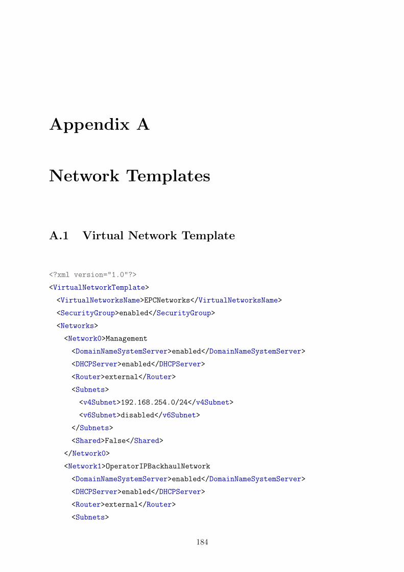
Appendix A
Network Templates
A.1 Virtual Network Template
<?xml version="1.0"?>
<VirtualNetworkTemplate>
<VirtualNetworksName>EPCNetworks</VirtualNetworksName>
<SecurityGroup>enabled</SecurityGroup>
<Networks>
<Network0>Management
<DomainNameSystemServer>enabled</DomainNameSystemServer>
<DHCPServer>enabled</DHCPServer>
<Router>external</Router>
<Subnets>
<v4Subnet>192.168.254.0/24</v4Subnet>
<v6Subnet>disabled</v6Subnet>
</Subnets>
<Shared>False</Shared>
</Network0>
<Network1>OperatorIPBackhaulNetwork
<DomainNameSystemServer>enabled</DomainNameSystemServer>
<DHCPServer>enabled</DHCPServer>
<Router>external</Router>
<Subnets>
184

APPENDIX A. NETWORK TEMPLATES 185
<v4Subnet>192.168.1.0/24</v4Subnet>
<v6Subnet>fc00:1234:1::/112</v6Subnet>
</Subnets>
<Shared>False</Shared>
</Network1>
<Network2>OperatorAccessBackhaulNetwork
<DomainNameSystemServer>enabled</DomainNameSystemServer>
<DHCPServer>enabled</DHCPServer>
<Router>None</Router>
<Subnets>
<v4Subnet>192.168.2.0/24</v4Subnet>
<v6Subnet>fc00:1234:2::/112</v6Subnet>
</Subnets>
<Shared>False</Shared>
</Network2>
<Network3>UserAccessNetwork
<DomainNameSystemServer>disabled</DomainNameSystemServer>
<DHCPServer>disabled</DHCPServer>
<Router>external</Router>
<Subnets>
<v4Subnet>192.168.3.0/24</v4Subnet>
<v6Subnet>fc00:1234:3::/128</v6Subnet>
</Subnets>
<Shared>False</Shared>
</Network3>
<Network4>OperatorGTPNetwork
<DomainNameSystemServer>enabled</DomainNameSystemServer>
<DHCPServer>enabled</DHCPServer>
<Router>None</Router>
<Subnets>
<v4Subnet>192.168.4.0/24</v4Subnet>
<v6Subnet>fc00:1234:4::/112</v6Subnet>
</Subnets>
<Shared>False</Shared>
</Network4>
<Network5>ProviderNetwork
<DomainNameSystemServer>disabled</DomainNameSystemServer>

APPENDIX A. NETWORK TEMPLATES 186
<DHCPServer>disabled</DHCPServer>
<Router>None</Router>
<Subnets>
<v4Subnet>137.158.126.32/27</v4Subnet>
<v6Subnet>2001:db8::/64</v6Subnet>
</Subnets>
<Shared>True</Shared>
</Network5>
</Networks>
</VirtualNetworkTemplate>

APPENDIX A. NETWORK TEMPLATES 187
A.2 VNF Templates
<?xml version="1.0"?>
<VirtualNetworkFunctionTemplate>
<VirtualNetworkFunctionName>EPDG</VirtualNetworkFunctionName>
<SecurityGroup>enabled</SecurityGroup>
<ImageName>epdg-image</ImageName>
<NetworkDescription>
<Networks>
<Network0>Management
<v4Subnet>192.168.254.0/24</v4Subnet>
</Network0>
<Network1>UserAccessNetwork
<v4Subnet>192.168.3.0/24</v4Subnet>
<v6Subnet>fc00:1234:3::/128</v6Subnet>
</Network1>
<Network2>OperatorAccessBackhaulNetwork
<v4Subnet>192.168.2.0/24</v4Subnet>
<v6Subnet>fc00:1234:2::/112</v6Subnet>
</Network2>
</Networks>
</NetworkDescription>
<VirtualResourceRequirements>
<vCPUs>2</vCPUs>
<RAM>2048</RAM>
<HD>10</HD>
</VirtualResourceRequirements>
<Enhancements>
<IPSecTunnelTermination>enabled</IPSecTunnelTermination>
<NetworkAcceleration>enabled</NetworkAcceleration>
<NetworkAccelerationType>KernalFastPath</NetworkAccelerationType>
<OffloadedNetworkProccesingUnit>IfAvailable</OffloadedNetworkProccesingUnit>
</Enhancements>
</VirtualNetworkFunctionTemplate>
Figure A.1: EPDG VNF MANO template

APPENDIX A. NETWORK TEMPLATES 188
<?xml version="1.0"?>
<VirtualNetworkFunctionTemplate>
<VirtualNetworkFunctionName>SGW</VirtualNetworkFunctionName>
<SecurityGroup>enabled</SecurityGroup>
<ImageName>sgw-image</ImageName>
<NetworkDescription>
<Networks>
<Network0>Management
<v4Subnet>192.168.254.0/24</v4Subnet>
</Network0>
<Network1>OperatorAccessBackhaulNetwork
<v4Subnet>192.168.2.0/24</v4Subnet>
<v6Subnet>fc00:1234:2::/112</v6Subnet>
</Network1>
<Network2>OperatorGTPNetwork
<v4Subnet>192.168.4.0/24</v4Subnet>
<v6Subnet>fc00:1234:4::/112</v6Subnet>
</Network2>
</Networks>
</NetworkDescription>
<VirtualResourceRequirements>
<vCPUs>3</vCPUs>
<RAM>4099</RAM>
<HD>10</HD>
</VirtualResourceRequirements>
<Enhancements>
<IPSecTunnelTermination>disabled</IPSecTunnelTermination>
<NetworkAcceleration>enabled</NetworkAcceleration>
<NetworkAccelerationType>KernalFastPath</NetworkAccelerationType>
<OffloadedNetworkProccesingUnit>disabled</OffloadedNetworkProccesingUnit>
</Enhancements>
</VirtualNetworkFunctionTemplate>
Figure A.2: SGW VNF MANO template

APPENDIX A. NETWORK TEMPLATES 189
<?xml version="1.0"?>
<VirtualNetworkFunctionTemplate>
<VirtualNetworkFunctionName>PGW</VirtualNetworkFunctionName>
<SecurityGroup>enabled</SecurityGroup>
<ImageName>pgw-image</ImageName>
<NetworkDescription>
<Networks>
<Network0>Management
<v4Subnet>192.168.254.0/24</v4Subnet>
</Network0>
<Network1>OperatorIPBackhaulNetwork
<v4Subnet>192.168.1.0/24</v4Subnet>
<v6Subnet>fc00:1234:1::/112</v6Subnet>
</Network1>
<Network2>OperatorAccessBackhaulNetwork
<v4Subnet>192.168.2.0/24</v4Subnet>
<v6Subnet>fc00:1234:2::/112</v6Subnet>
</Network2>
</Networks>
</NetworkDescription>
<VirtualResourceRequirements>
<vCPUs>4</vCPUs>
<RAM>4096</RAM>
<HD>10</HD>
</VirtualResourceRequirements>
<Enhancements>
<IPSecTunnelTermination>disabled</IPSecTunnelTermination>
<NetworkAcceleration>enabled</NetworkAcceleration>
<NetworkAccelerationType>KernalFastPath</NetworkAccelerationType>
<OffloadedNetworkProccesingUnit>disabled</OffloadedNetworkProccesingUnit>
</Enhancements>
</VirtualNetworkFunctionTemplate>
Figure A.3: PGW VNF MANO template

APPENDIX A. NETWORK TEMPLATES 190
<?xml version="1.0"?>
<VirtualNetworkFunctionTemplate>
<VirtualNetworkFunctionName>IMSFunction</VirtualNetworkFunctionName>
<SecurityGroup>enabled</SecurityGroup>
<ImageName>ims-enablers-image</ImageName>
<NetworkDescription>
<Networks>
<Network0>Management
<v4Subnet>192.168.254.0/24</v4Subnet>
</Network0>
<Network1>OperatorIPBackhaulNetwork
<v4Subnet>192.168.1.0/24</v4Subnet>
<v6Subnet>fc00:1234:1::/112</v6Subnet>
</Network1>
</Networks>
</NetworkDescription>
<VirtualResourceRequirements>
<vCPUs>3</vCPUs>
<RAM>4096</RAM>
<HD>10</HD>
</VirtualResourceRequirements>
<Enhancements>
<IPSecTunnelTermination>disabled</IPSecTunnelTermination>
<NetworkAcceleration>enabled</NetworkAcceleration>
<NetworkAccelerationType>UserSpaceFastPath</NetworkAccelerationType>
<OffloadedNetworkProccesingUnit>disabled</OffloadedNetworkProccesingUnit>
</Enhancements>
</VirtualNetworkFunctionTemplate>
Figure A.4: IMS VNF MANO template

APPENDIX A. NETWORK TEMPLATES 191
<?xml version="1.0"?>
<VirtualNetworkFunctionTemplate>
<VirtualNetworkFunctionName>PolicyChargingControlFunction</VirtualNetworkFunctionName>
<SecurityGroup>enabled</SecurityGroup>
<ImageName>ims-enablers-image</ImageName>
<NetworkDescription>
<Networks>
<Network0>Management
<v4Subnet>192.168.254.0/24</v4Subnet>
</Network0>
</Networks>
</NetworkDescription>
<VirtualResourceRequirements>
<vCPUs>3</vCPUs>
<RAM>4096</RAM>
<HD>10</HD>
</VirtualResourceRequirements>
<Enhancements>
<IPSecTunnelTermination>disabled</IPSecTunnelTermination>
<NetworkAcceleration>enabled</NetworkAcceleration>
<NetworkAccelerationType>UserSpaceFastPath</NetworkAccelerationType>
<OffloadedNetworkProccesingUnit>disabled</OffloadedNetworkProccesingUnit>
</Enhancements>
</VirtualNetworkFunctionTemplate>
Figure A.5: PCC VNF MANO template

APPENDIX A. NETWORK TEMPLATES 192
<?xml version="1.0"?>
<VirtualNetworkFunctionTemplate>
<VirtualNetworkFunctionName>MachineTypeCommunicationFunction</VirtualNetworkFunctionName>
<SecurityGroup>enabled</SecurityGroup>
<ImageName>ims-enablers-image</ImageName>
<NetworkDescription>
<Networks>
<Network0>Management
<v4Subnet>192.168.254.0/24</v4Subnet>
</Network0>
<Network1>OperatorIPBackhaulNetwork
<v4Subnet>192.168.1.0/24</v4Subnet>
<v6Subnet>fc00:1234:1::/112</v6Subnet>
</Network1>
</Networks>
</NetworkDescription>
<VirtualResourceRequirements>
<vCPUs>3</vCPUs>
<RAM>4096</RAM>
<HD>10</HD>
</VirtualResourceRequirements>
<Enhancements>
<IPSecTunnelTermination>disabled</IPSecTunnelTermination>
<NetworkAcceleration>enabled</NetworkAcceleration>
<NetworkAccelerationType>UserSpaceFastPath</NetworkAccelerationType>
<OffloadedNetworkProccesingUnit>disabled</OffloadedNetworkProccesingUnit>
</Enhancements>
</VirtualNetworkFunctionTemplate>
Figure A.6: MTC-SERVER VNF MANO template

APPENDIX A. NETWORK TEMPLATES 193
<?xml version="1.0"?>
<VirtualNetworkFunctionTemplate>
<VirtualNetworkFunctionName>MTCFunction</VirtualNetworkFunctionName>
<SecurityGroup>enabled</SecurityGroup>
<ImageName>ims-enablers-image</ImageName>
<NetworkDescription>
<Networks>
<Network0>Management
<v4Subnet>192.168.254.0/24</v4Subnet>
</Network0>
<Network1>OperatorIPBackhaulNetwork
<v4Subnet>192.168.1.0/24</v4Subnet>
<v6Subnet>fc00:1234:1::/112</v6Subnet>
</Network1>
</Networks>
</NetworkDescription>
<VirtualResourceRequirements>
<vCPUs>3</vCPUs>
<RAM>4096</RAM>
<HD>10</HD>
</VirtualResourceRequirements>
<Enhancements>
<IPSecTunnelTermination>disabled</IPSecTunnelTermination>
<NetworkAcceleration>enabled</NetworkAcceleration>
<NetworkAccelerationType>UserSpaceFastPath</NetworkAccelerationType>
<OffloadedNetworkProccesingUnit>disabled</OffloadedNetworkProccesingUnit>
</Enhancements>
</VirtualNetworkFunctionTemplate>
Figure A.7: MTC-Gateway VNF MANO template

APPENDIX A. NETWORK TEMPLATES 194
<?xml version="1.0"?>
<VirtualNetworkFunctionTemplate>
<VirtualNetworkFunctionName>MediaDeliveryFunction</VirtualNetworkFunctionName>
<SecurityGroup>enabled</SecurityGroup>
<ImageName>ims-enablers-image</ImageName>
<NetworkDescription>
<Networks>
<Network0>Management
<v4Subnet>192.168.254.0/24</v4Subnet>
</Network0>
<Network1>OperatorIPBackhaulNetwork
<v4Subnet>192.168.1.0/24</v4Subnet>
<v6Subnet>fc00:1234:1::/112</v6Subnet>
</Network1>
</Networks>
</NetworkDescription>
<VirtualResourceRequirements>
<vCPUs>3</vCPUs>
<RAM>4096</RAM>
<HD>10</HD>
</VirtualResourceRequirements>
<Enhancements>
<IPSecTunnelTermination>disabled</IPSecTunnelTermination>
<NetworkAcceleration>enabled</NetworkAcceleration>
<NetworkAccelerationType>UserSpaceFastPath</NetworkAccelerationType>
<OffloadedNetworkProccesingUnit>disabled</OffloadedNetworkProccesingUnit>
</Enhancements>
</VirtualNetworkFunctionTemplate>
Figure A.8: CDN VNF MANO template

Appendix B
Evaluation Framework Hardware
Specifications
Table B.1 gives the hardware profiles of the OpenStack date centre nodes.
Table B.1: OpenStack Hardware Specifications
Control Node Network Node Compute Node
(x3)
Processor Intel(R)
Core(TM)
i5-3340 CPU
Intel(R)
Core(TM)
i3-2100
Intel(R)
Xeon(R) CPU
E5-2407 v2
CPU (GHz) 3.10 3.10 2.40
Processor cores 4 4 8
RAM (GB) 8 8 32
OS (Ubuntu) 16.04.2 LTS LTS
Xenial Xerus
16.04.2 LTS LTS
Xenial Xerus
16.04.2 LTS LTS
Xenial Xerus
OS Kernel 4.2.0-27 4.2.0-27 4.9.0-040900
Table B.2 gives the hardware profiles of the data centre administration nodes.
195

APPENDIX B. EVALUATION FRAMEWORK HARDWARE SPECIFICATIONS 196
Table B.2: Administration Hardware Specifications
Monitoring
Node
OpenDaylight
Node
Processor Intel(R)
Genuine CPU
Intel(R)
Core(TM)
i7-4771
CPU (GHz) 1.50 3.50
Processor cores 4 4
RAM (GB) 4 16
OS (Ubuntu) 16.04.4 LTS
Xenial Xerus
16.04.1 LTS
Xenial Xerus
OS Kernel 4.2.0-27 3.13.0-49