Embed Size (px)
Citation preview
InfraMation 2004 Proceedings ITC 104 A 2004-07-27
Infrared Applications for Post Construction Radiant Heating Systems Eric G. Amhaus, Professional Investigative Engineers Edward L. Fronapfel, Professional Investigative Engineers
ABSTRACT
This paper will review and discuss the benefits of infrared thermography as its technology applies to the investigations and inspections of various in-floor (interior) and concrete slab (interior and exterior) radiant heating systems, both electrical and fluid systems. The purpose of this paper is to outline the various applications of infrared thermography for investigation of the systems, as presented in a case study format. The technique illustrates how infrared thermal imaging cameras can be utilized to determine such post-construction items as identification of system zones, failure or impeded heat loss analysis, sensor identification, leak analysis, and line system identifications for intrusive testing or slab coring. Both resistance electrical and fluid radiant heat systems have become widely used in high-altitude and cold, mountainous regions such as Colorado. Initially, the objective of such systems was to reduce the need for manual methods of snow and ice removal from pedestrian or vehicular surfaces, but these systems have recently become fairly common forms of residential interior heating and temperature control in higher end homes. Manufacturer and design deficiencies, as well as installation defects, result in system malfunctions and non-performance issues. The cost of the failures is staggering, considering the cost to remove finish materials, determine the location of the problem, and then rebuild the system and replace the finish materials. Infrared thermography can help identify and aid in the development of positive solutions both in the post construction and pre-construction stages. Keywords: In-floor, interior, exterior, slab, radiant, electrical, fluid, construction, zoning, sensor, leak, testing, cold, mountainous, heating, temperature, homes, construction. INTRODUCTION AND HISTORY
Radiant heating systems were first invented and utilized by the Romans and ancient Koreans, who built fireplaces (i.e., furnaces) with extended flues under rock or masonry floors for natural heat distribution. Hydronic (or hot water-based) radiant flooring was founded in the United States beginning in the late 1930’s. These systems primarily consisted of wrought iron pipe, but they were quickly abandoned with the outbreak of World War II, when the demand for steel and iron was great. Shortly thereafter, radiant heat systems in the U.S. began to utilize soft copper tubing; however, systematic failures were identified in these systems due to electrolytic corrosion between the copper and concrete reinforcement and line breakage due to the movement of concrete (settlement, heave, expansion, and contraction). With the new era and advent of plastics, in-floor radiant heating manufacturers turned to the new technology of plastics for advancements with in-floor heating elements. This paper will not attempt to encompass or address the varying types of radiant heating systems and their positive performance characteristics or failure mechanisms, but rather, it will set forth a means by which infrared thermography can be utilized as a valuable tool in investigating performance flaws and design or installation deficiencies in these types of heating systems. INTERIOR SYSTEM PERFORMANCE AND ZONING
Similar to almost any other construction element, proper design and installation of an in-floor radiant heat system (fluid or electrical) are vital to proper system performance. Infrared thermography can be utilized to detect such design or installation deficiencies that result in system failures or inadequate performance.
InfraMation 2004 Proceedings ITC 104 A 2004-07-27
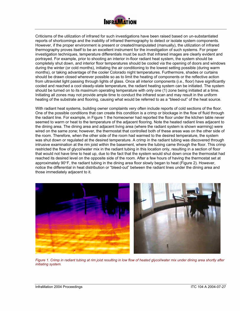
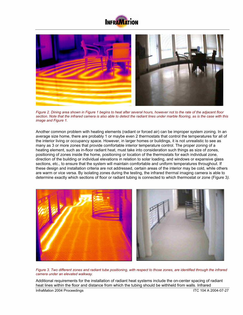
Criticisms of the utilization of infrared for such investigations have been raised based on un-substantiated reports of shortcomings and the inability of infrared thermography to detect or isolate system components. However, if the proper environment is present or created/manipulated (manually), the utilization of infrared thermography proves itself to be an excellent instrument for the investigation of such systems. For proper investigation techniques, temperature differentials must be such that infrared images are clearly evident and portrayed. For example, prior to shooting an interior in-floor radiant heat system, the system should be completely shut down, and interior floor temperatures should be cooled via the opening of doors and windows during the winter (or cold months), initiating the air conditioning to the lowest setting possible (during warm months), or taking advantage of the cooler Colorado night temperatures. Furthermore, shades or curtains should be drawn closed wherever possible so as to limit the heating of components or the reflective action from ultraviolet light passing through lights of glass. Once all interior components (i.e., floor) have significantly cooled and reached a cool steady-state temperature, the radiant heating system can be initiated. The system should be turned on to its maximum operating temperature with only one (1) zone being initiated at a time. Initiating all zones may not provide ample time to conduct the infrared scan and may result in the uniform heating of the substrate and flooring, causing what would be referred to as a “bleed-out” of the heat source. With radiant heat systems, building owner complaints very often include reports of cold sections of the floor. One of the possible conditions that can create this condition is a crimp or blockage in the flow of fluid through the radiant line. For example, in Figure 1 the homeowner had reported the floor under the kitchen table never seemed to warm or heat to the temperature of the adjacent flooring. Note the heated radiant lines adjacent to the dining area. The dining area and adjacent living area (where the radiant system is shown warming) were wired on the same zone; however, the thermostat that controlled both of these areas was on the other side of the room. Therefore, when the other side of the room had warmed to the desired temperature, the system was shut down or regulated at the desired temperature. A crimp in the radiant tubing was discovered through intrusive examination at the rim joist within the basement, where the tubing came through the floor. This crimp restricted the flow of glycol/water mix in the radiant tubing in this location only, resulting in a section of floor that would not have time to heat up, due to the fact that the system would shut down once the thermostat had reached its desired level on the opposite side of the room. After a few hours of having the thermostat set at approximately 90°F, the radiant tubing in the dining area floor slowly began to heat (Figure 2). However, notice the differential in heat distribution or “bleed-out” between the radiant lines under the dining area and those immediately adjacent to it.
Figure 1. Crimp in radiant tubing at rim joist resulting in low flow of heated glycol/water mix under dining area shortly after initiating system.
InfraMation 2004 Proceedings ITC 104 A 2004-07-27
Figure 2. Dining area shown in Figure 1 begins to heat after several hours, however not to the rate of the adjacent floor section. Note that the infrared camera is also able to detect the radiant lines under marble flooring, as is the case with this image and Figure 1.
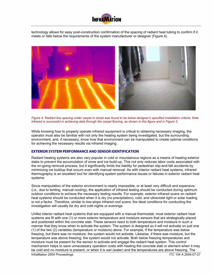
Another common problem with heating elements (radiant or forced air) can be improper system zoning. In an average size home, there are probably 1 or maybe even 2 thermostats that control the temperatures for all of the interior living or occupancy space. However, in larger homes or buildings, it is not unrealistic to see as many as 3 or more zones that provide comfortable interior temperature control. The proper zoning of a heating element, such as in-floor radiant heat, must take into consideration such things as size of zones, positioning of zones inside the home, positioning or location of the thermostats for each individual zone, direction of the building or individual elevations in relation to solar loading, and windows or expansive glass sections, etc., to ensure that the system will maintain comfortable and uniform temperatures throughout. If these design and installation criteria are not addressed, certain areas of the interior may be cold, while others are warm or vice versa. By isolating zones during the testing, the infrared thermal imaging camera is able to determine exactly which sections of floor or radiant tubing is connected to which thermostat or zone (Figure 3).
Figure 3. Two different zones and radiant tube positioning, with respect to those zones, are identified through the infrared camera under an elevated walkway.
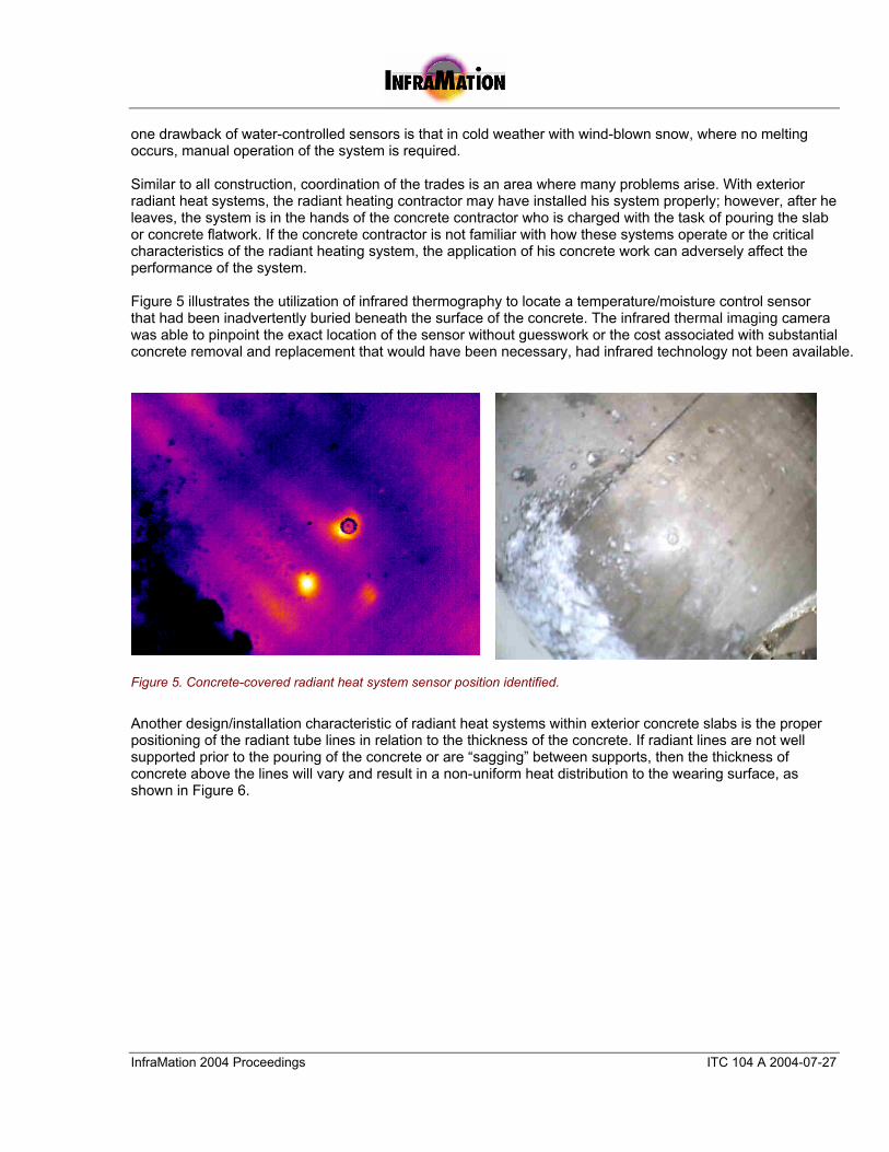
Additional requirements for the installation of radiant heat systems include the on-center spacing of radiant heat lines within the floor and distance from which the tubing should be withheld from walls. Infrared
InfraMation 2004 Proceedings ITC 104 A 2004-07-27
technology allows for easy post-construction confirmation of the spacing of radiant heat tubing to confirm if it meets or falls below the requirements of the system manufacturer or designer (Figure 4).
Figure 4. Radiant line spacing under carpet in closet was found to be below designer’s specified installation criteria. Note infrared is successful in achieving data through the carpet flooring, as shown in this figure and in Figure 3.
While knowing how to properly operate infrared equipment is critical to obtaining necessary imaging, the operator must also be familiar with not only the heating system being investigated, but the surrounding environment, and, if necessary, know how that environment can be manipulated to create optimal conditions for achieving the necessary results via infrared imaging. EXTERIOR SYSTEM PERFORMANCE AND SENSOR IDENTIFICATION
Radiant heating systems are also very popular in cold or mountainous regions as a means of heating exterior slabs to prevent the accumulation of snow and ice build-up. This not only reduces labor costs associated with the on-going removal process, but it significantly limits the liability for pedestrian slip-and-fall accidents by minimizing ice buildup that occurs even with manual removal. As with interior radiant heat systems, infrared thermography is an excellent tool for identifying system performance issues or failures in exterior radiant heat systems. Since manipulation of the exterior environment is nearly impossible, or at least very difficult and expensive (i.e., due to tenting, manual cooling), the application of infrared testing should be conducted during optimum outdoor conditions to achieve the necessary testing results. For example, exterior infrared scans on radiant heat systems should be conducted when it is dry (no precipitation), cold, and ultraviolet light or solar loading is not a factor. Therefore, similar to low-slope infrared roof scans, the ideal conditions for conducting the investigation will usually be dry and cold nights or evenings. Unlike interior radiant heat systems that are equipped with a manual thermostat, most exterior radiant heat systems are fit with one (1) or more exterior temperature and moisture sensors that are strategically placed and positioned within the concrete slab. These sensors react to both temperature and moisture in such a manner that they know when to activate the system. The system is designed so it will not activate on just one (1) of the two (2) variables (temperature or moisture) alone. For example, if the temperature was below freezing, but there was no moisture, the system would not activate. Likewise, if there was moisture, but the temperature was above freezing, the system would not activate. Both below freezing temperatures and moisture must be present for the sensor to activate and engage the radiant heat system. This control mechanism helps to save unnecessary operation costs with heating the concrete slab or element when it may be cold and no moisture is present, or when it is wet (water) and the temperatures are above freezing. The
InfraMation 2004 Proceedings ITC 104 A 2004-07-27
one drawback of water-controlled sensors is that in cold weather with wind-blown snow, where no melting occurs, manual operation of the system is required. Similar to all construction, coordination of the trades is an area where many problems arise. With exterior radiant heat systems, the radiant heating contractor may have installed his system properly; however, after he leaves, the system is in the hands of the concrete contractor who is charged with the task of pouring the slab or concrete flatwork. If the concrete contractor is not familiar with how these systems operate or the critical characteristics of the radiant heating system, the application of his concrete work can adversely affect the performance of the system. Figure 5 illustrates the utilization of infrared thermography to locate a temperature/moisture control sensor that had been inadvertently buried beneath the surface of the concrete. The infrared thermal imaging camera was able to pinpoint the exact location of the sensor without guesswork or the cost associated with substantial concrete removal and replacement that would have been necessary, had infrared technology not been available.
Figure 5. Concrete-covered radiant heat system sensor position identified.
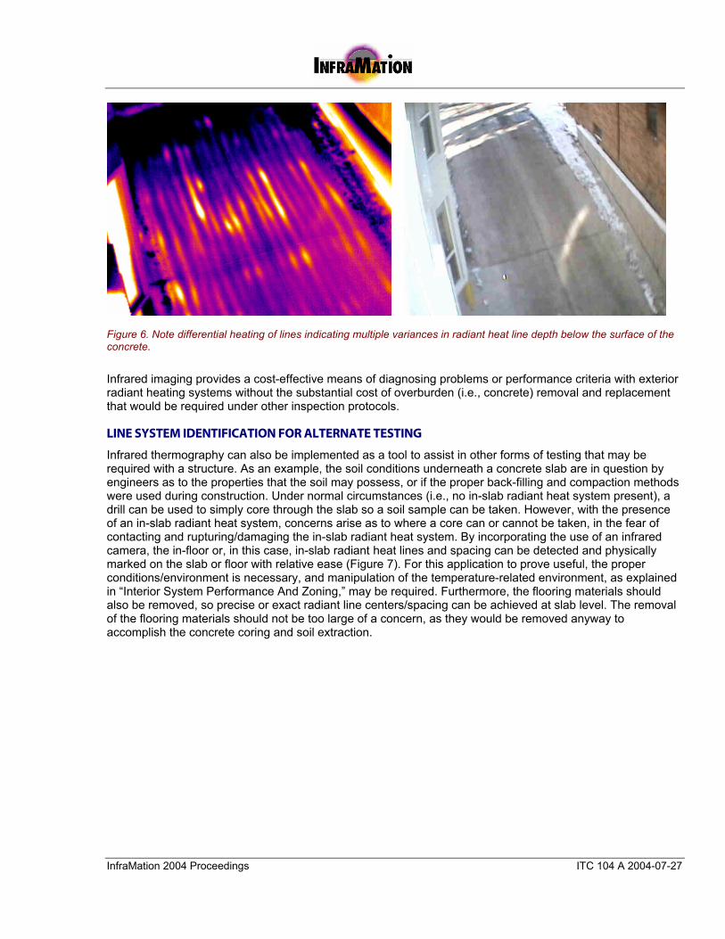
Another design/installation characteristic of radiant heat systems within exterior concrete slabs is the proper positioning of the radiant tube lines in relation to the thickness of the concrete. If radiant lines are not well supported prior to the pouring of the concrete or are “sagging” between supports, then the thickness of concrete above the lines will vary and result in a non-uniform heat distribution to the wearing surface, as shown in Figure 6.
InfraMation 2004 Proceedings ITC 104 A 2004-07-27
Figure 6. Note differential heating of lines indicating multiple variances in radiant heat line depth below the surface of the concrete.
Infrared imaging provides a cost-effective means of diagnosing problems or performance criteria with exterior radiant heating systems without the substantial cost of overburden (i.e., concrete) removal and replacement that would be required under other inspection protocols. LINE SYSTEM IDENTIFICATION FOR ALTERNATE TESTING
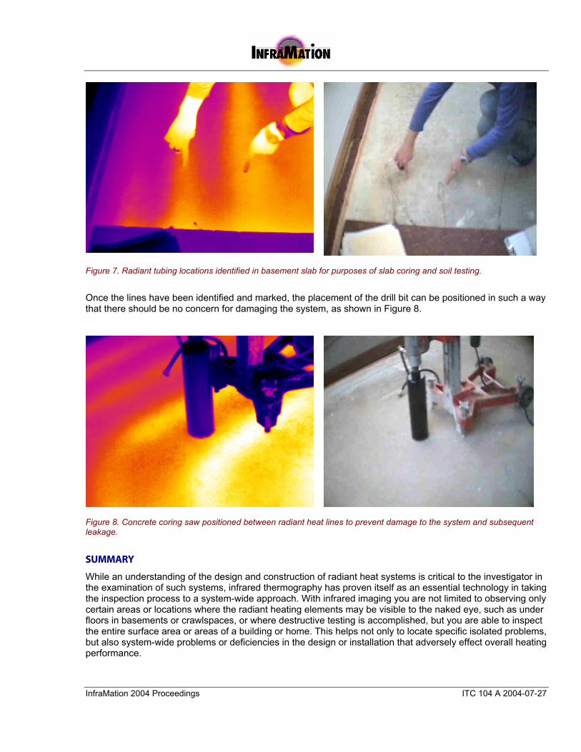
Infrared thermography can also be implemented as a tool to assist in other forms of testing that may be required with a structure. As an example, the soil conditions underneath a concrete slab are in question by engineers as to the properties that the soil may possess, or if the proper back-filling and compaction methods were used during construction. Under normal circumstances (i.e., no in-slab radiant heat system present), a drill can be used to simply core through the slab so a soil sample can be taken. However, with the presence of an in-slab radiant heat system, concerns arise as to where a core can or cannot be taken, in the fear of contacting and rupturing/damaging the in-slab radiant heat system. By incorporating the use of an infrared camera, the in-floor or, in this case, in-slab radiant heat lines and spacing can be detected and physically marked on the slab or floor with relative ease (Figure 7). For this application to prove useful, the proper conditions/environment is necessary, and manipulation of the temperature-related environment, as explained in “Interior System Performance And Zoning,” may be required. Furthermore, the flooring materials should also be removed, so precise or exact radiant line centers/spacing can be achieved at slab level. The removal of the flooring materials should not be too large of a concern, as they would be removed anyway to accomplish the concrete coring and soil extraction.
InfraMation 2004 Proceedings ITC 104 A 2004-07-27
Figure 7. Radiant tubing locations identified in basement slab for purposes of slab coring and soil testing.
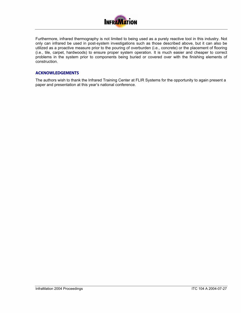
Once the lines have been identified and marked, the placement of the drill bit can be positioned in such a way that there should be no concern for damaging the system, as shown in Figure 8.
Figure 8. Concrete coring saw positioned between radiant heat lines to prevent damage to the system and subsequent leakage.
SUMMARY
While an understanding of the design and construction of radiant heat systems is critical to the investigator in the examination of such systems, infrared thermography has proven itself as an essential technology in taking the inspection process to a system-wide approach. With infrared imaging you are not limited to observing only certain areas or locations where the radiant heating elements may be visible to the naked eye, such as under floors in basements or crawlspaces, or where destructive testing is accomplished, but you are able to inspect the entire surface area or areas of a building or home. This helps not only to locate specific isolated problems, but also system-wide problems or deficiencies in the design or installation that adversely effect overall heating performance.
InfraMation 2004 Proceedings ITC 104 A 2004-07-27
Furthermore, infrared thermography is not limited to being used as a purely reactive tool in this industry. Not only can infrared be used in post-system investigations such as those described above, but it can also be utilized as a proactive measure prior to the pouring of overburden (i.e., concrete) or the placement of flooring (i.e., tile, carpet, hardwoods) to ensure proper system operation. It is much easier and cheaper to correct problems in the system prior to components being buried or covered over with the finishing elements of construction.
ACKNOWLEDGEMENTS
The authors wish to thank the Infrared Training Center at FLIR Systems for the opportunity to again present a paper and presentation at this year’s national conference.