Embed Size (px)
Citation preview

Servo Cylinder Info & User Manual 1
Version: A.07 D/N: UM711293
Information & User Manual
Electromechanical Linear Actuator with Fully Integrated Phase Index™ Control System
A1 and A2 Series Servo Cylinder Actuators
A1-Series: Standard Servo Cylinder Actuator
A2-Series: Sealed Servo Cylinder Actuator
Servo Cylinder Info & User Manual 2
Version: A.07 D/N: UM711293
Safety Information
IMPORTANT: Read this manual before installing and operating the Ultra Motion Servo Cylinder. Failure to read this
section can result in personal harm or damage to the product.
Safety Disclaimer
The Servo Cylinder is intended to be a subcomponent of a larger piece of machinery or automated system. This
section is not intended to provide the safety guidelines for the entire machine or system that the Servo Cylinder is
installed into. It is the responsibility of the purchaser or system designer to assess the risks and safety
requirements of the end application they are designing.
If the Servo Cylinder is to be used in a safety critical application, the purchaser or system designer must perform
appropriate safety testing to ensure that the product meets the requirements and safety criteria for their
application.
Ultra Motion has made all reasonable efforts to present accurate information in this document and is not
responsible for unintentional oversights. If, at any time, the purchaser has questions or uncertainty about
information in this manual, contact Ultra Motion to speak with an engineer.
Safety Warnings
• Once powered, the Servo Cylinder is capable of rapid motion and can produce large amounts of force.
Always ensure that safe clearances from body parts and other equipment are maintained before applying
power.
• The Servo Cylinder operates on low voltage (8 to 36 VDC recommended). However, still use caution when
handling and working around the actuator to avoid electrical shock.
• At high current draws, motor of the actuator can become very hot. Take adequate time to cool before
handling.
• Provide adequate ventilation for cooling of this device.
Safety Notifications
As you read through the manual, you will notice certain safety notifications that indicate other important
safety related information.
Servo Cylinder Info & User Manual 3
Version: A.07 D/N: UM711293
Contents
Safety Information.................................................................................................................................................................................. 2 Introduction ............................................................................................................................................................................................. 5 Product Information ............................................................................................................................................................................... 6
Features .......................................................................................................................................................................................................... 6 Performance Characteristics ........................................................................................................................................................................ 6 Compatible Control Signals & Operating Modes ....................................................................................................................................... 6
Command Line Interface (CLI) RS232 Serial Mode ........................................................................................................................................................ 6 Analog Voltage ................................................................................................................................................................................................................... 7 Analog Current .................................................................................................................................................................................................................. 7 1-2ms Pulse (PWM) ........................................................................................................................................................................................................... 7 Step & Direction ................................................................................................................................................................................................................ 7 A/B Quadrature ................................................................................................................................................................................................................. 7 CW/CCW ............................................................................................................................................................................................................................. 7 Toggle Mode ...................................................................................................................................................................................................................... 7 Preset Position Mode ........................................................................................................................................................................................................ 7
Integrated Field-Oriented (FOC) Motor Control System with Phase Index™ Feedback ........................................................................ 8 What is Phase Index™? ..................................................................................................................................................................................................... 8 How is Phase Index™ used in Servo Cylinder? ............................................................................................................................................................... 8 Advantages of Field-Oriented (FOC) Motor Commutation ............................................................................................................................................ 8 High Performance Electronics.......................................................................................................................................................................................... 8
Mechanical Design ........................................................................................................................................................................................ 9 Mechanical Interface & Dimensions ................................................................................................................................................................................ 9
Design Guidelines and Best Practices for Electromechanical Actuators ..................................................................................... 10 Requirements and Specifications ....................................................................................................................................................... 11
Mechanical Performance ............................................................................................................................................................................ 11 Maximum Continuous Load Derating (for Elevated Temperature Environments) .................................................................................................. 11
Electrical Interface ....................................................................................................................................................................................... 12 A1 Series Actuator Pinout ............................................................................................................................................................................................... 12 A2 Series Actuator Pinout ............................................................................................................................................................................................... 12
Electrical Input and Output Specifications ............................................................................................................................................... 12 Power Supply Input (V+) ................................................................................................................................................................................................. 12 Analog Current Input (ANI) ............................................................................................................................................................................................. 14 Analog Voltage Input (ANV) ............................................................................................................................................................................................ 15 Optically Isolated Digital Inputs (IN1+, IN1-, IN2+, and IN2-) ...................................................................................................................................... 15 RS232 Serial Input (TX and RX) ....................................................................................................................................................................................... 16 General Purpose Input/Outputs (GPIOs) (DIO1 and DIO2) ......................................................................................................................................... 16
Cabling .......................................................................................................................................................................................................... 16 Purchasing Cables from Ultra Motion ........................................................................................................................................................................... 16
Initial Setup ............................................................................................................................................................................................ 20
Getting Started............................................................................................................................................................................................. 20 Setting up the Servo Cylinder Hardware .................................................................................................................................................. 20 Additional Setup Information for A2-Series Actuators ........................................................................................................................... 21
Installing A2 Series Cables .............................................................................................................................................................................................. 21 Configuring A2 Series Servo Cylinders over USB ......................................................................................................................................................... 21
Configuration ......................................................................................................................................................................................... 22 How to Configure with USB Mass Storage .................................................................................................................................................................... 22 Default “Factory Set” Behavior ....................................................................................................................................................................................... 23
Configuration Variable Definitions (within CONFIG.TXT) ........................................................................................................................ 24 General Configuration Variables ................................................................................................................................................................................... 24 Shared Configuration Variables ..................................................................................................................................................................................... 26 Command Line Interface (CLI) Mode Configuration .................................................................................................................................................... 28 Proportional Mode Configuration Parameters ............................................................................................................................................................ 28 Incremental Mode Configuration (Step & Direction, A/B Quadrature, CW/CCW) ..................................................................................................... 30 Toggle Mode Configuration ............................................................................................................................................................................................ 31

Servo Cylinder Info & User Manual 4
Version: A.07 D/N: UM711293
Preset Position Mode Configuration ............................................................................................................................................................................. 31
Configuring Outputs and Diagnostics ....................................................................................................................................................... 32 Configuring General Purpose Input / Outputs (GPIO’s) ............................................................................................................................................... 32 Data Streaming ................................................................................................................................................................................................................ 32
Installation and Use ............................................................................................................................................................................. 35
Integrating Servo Cylinder into Your System ........................................................................................................................................... 35 Using the Command Line Interface (CLI) .................................................................................................................................................. 35
Setting up a PuTTY Terminal (in Windows) ................................................................................................................................................................... 35 Information about the Command Line Interface ......................................................................................................................................................... 36 Using Machine Mode for ACK/NACK and Checksum Validation ................................................................................................................................. 37
Using the Status Register Feature ............................................................................................................................................................. 39 User Settable Status Bit Thresholds .............................................................................................................................................................................. 39 Reading the Status Register over Serial ........................................................................................................................................................................ 40 Reading the Status Register over the General Purpose I/O Pins (DIO1 and DIO2)................................................................................................... 40
Tuning Performance ................................................................................................................................................................................... 41 Proportional Term ........................................................................................................................................................................................................... 42 Integral Term ................................................................................................................................................................................................................... 43 Derivative Term ............................................................................................................................................................................................................... 43 Stability ............................................................................................................................................................................................................................. 44 Adjusting Gain Values from Factory Defaults ............................................................................................................................................................... 45
Updating the Firmware ............................................................................................................................................................................... 45 Firmware Updating Procedure ...................................................................................................................................................................................... 46
Troubleshooting .................................................................................................................................................................................... 49
Status Light Definitions ............................................................................................................................................................................... 49
Appendix A: Serial Command Line Interface (CLI) List of Commands .......................................................................................... 50
Read Commands ......................................................................................................................................................................................... 51 Set Commands ............................................................................................................................................................................................ 52 System Commands ..................................................................................................................................................................................... 55 Trajectory Commands ................................................................................................................................................................................ 56 Serial Data Streaming ................................................................................................................................................................................. 58
Appendix B: Firmware Changelog ...................................................................................................................................................... 60 Contact Information ............................................................................................................................................................................. 61
Servo Cylinder Info & User Manual 5
Version: A.07 D/N: UM711293
Introduction
The Ultra Motion Servo Cylinder is a high performance linear servo system comprised of a robust rod-style actuator,
a configurable brushless DC (BLDC) motor controller, and the cutting edge multi-turn absolute feedback technology
Phase Index™. All components of the system have been engineered to seamlessly work together and provide a
simple and extremely reliable linear positioning device.
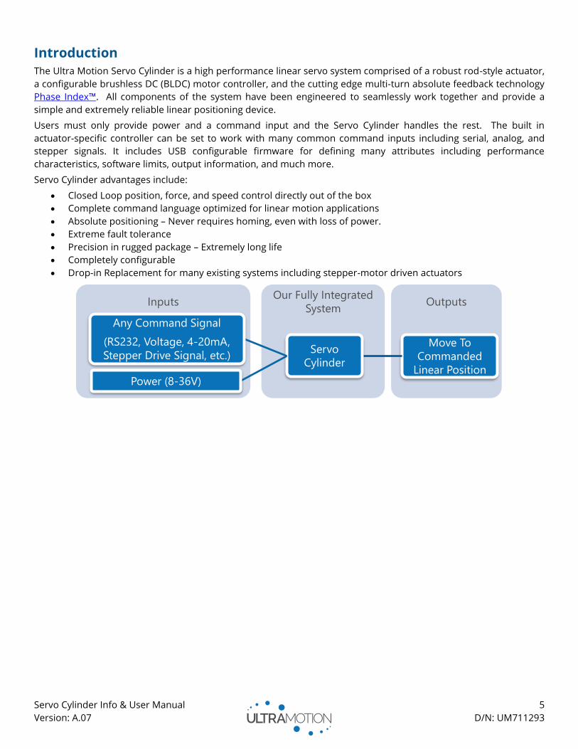
Users must only provide power and a command input and the Servo Cylinder handles the rest. The built in
actuator-specific controller can be set to work with many common command inputs including serial, analog, and
stepper signals. It includes USB configurable firmware for defining many attributes including performance
characteristics, software limits, output information, and much more.
Servo Cylinder advantages include:
• Closed Loop position, force, and speed control directly out of the box
• Complete command language optimized for linear motion applications
• Absolute positioning – Never requires homing, even with loss of power.
• Extreme fault tolerance
• Precision in rugged package – Extremely long life
• Completely configurable
• Drop-in Replacement for many existing systems including stepper-motor driven actuators
InputsOur Fully Integrated
SystemOutputs
Move To
Commanded
Linear Position
Servo
Cylinder
Any Command Signal
(RS232, Voltage, 4-20mA,
Stepper Drive Signal, etc.)
Power (8-36V)
Servo Cylinder Info & User Manual 6
Version: A.07 D/N: UM711293
Product Information
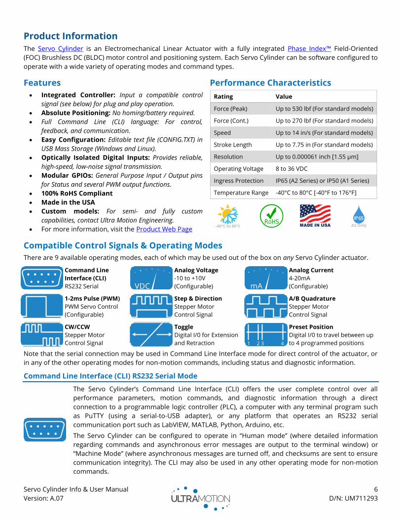
The Servo Cylinder is an Electromechanical Linear Actuator with a fully integrated Phase Index™ Field-Oriented
(FOC) Brushless DC (BLDC) motor control and positioning system. Each Servo Cylinder can be software configured to
operate with a wide variety of operating modes and command types.
Features Performance Characteristics
• Integrated Controller: Input a compatible control
signal (see below) for plug and play operation.
• Absolute Positioning: No homing/battery required.
• Full Command Line (CLI) language: For control,
feedback, and communication.
• Easy Configuration: Editable text file (CONFIG.TXT) in
USB Mass Storage (Windows and Linux).
• Optically Isolated Digital Inputs: Provides reliable,
high-speed, low-noise signal transmission.
• Modular GPIOs: General Purpose Input / Output pins
for Status and several PWM output functions.
• 100% RoHS Compliant
• Made in the USA
• Custom models: For semi- and fully custom
capabilities, contact Ultra Motion Engineering.
• For more information, visit the Product Web Page
Rating Value
Force (Peak) Up to 530 lbf (For standard models)
Force (Cont.) Up to 270 lbf (For standard models)
Speed Up to 14 in/s (For standard models)
Stroke Length Up to 7.75 in (For standard models)
Resolution Up to 0.000061 inch [1.55 µm]
Operating Voltage 8 to 36 VDC
Ingress Protection IP65 (A2 Series) or IP50 (A1 Series)
Temperature Range -40°C to 80°C [-40°F to 176°F]
Compatible Control Signals & Operating Modes
There are 9 available operating modes, each of which may be used out of the box on any Servo Cylinder actuator.
Command Line
Interface (CLI)
RS232 Serial
Analog Voltage
-10 to +10V
(Configurable)
Analog Current
4-20mA
(Configurable)
1-2ms Pulse (PWM)
PWM Servo Control
(Configurable)
Step & Direction
Stepper Motor
Control Signal
A/B Quadrature
Stepper Motor
Control Signal
CW/CCW
Stepper Motor
Control Signal
Toggle
Digital I/0 for Extension
and Retraction
Preset Position
Digital I/0 to travel between up
to 4 programmed positions
Note that the serial connection may be used in Command Line Interface mode for direct control of the actuator, or
in any of the other operating modes for non-motion commands, including status and diagnostic information.
Command Line Interface (CLI) RS232 Serial Mode
The Servo Cylinder’s Command Line Interface (CLI) offers the user complete control over all
performance parameters, motion commands, and diagnostic information through a direct
connection to a programmable logic controller (PLC), a computer with any terminal program such
as PuTTY (using a serial-to-USB adapter), or any platform that operates an RS232 serial
communication port such as LabVIEW, MATLAB, Python, Arduino, etc.
The Servo Cylinder can be configured to operate in “Human mode” (where detailed information
regarding commands and asynchronous error messages are output to the terminal window) or
“Machine Mode” (where asynchronous messages are turned off, and checksums are sent to ensure
communication integrity). The CLI may also be used in any other operating mode for non-motion
commands.
-40°C to 80°C A2 Only
Servo Cylinder Info & User Manual 7
Version: A.07 D/N: UM711293
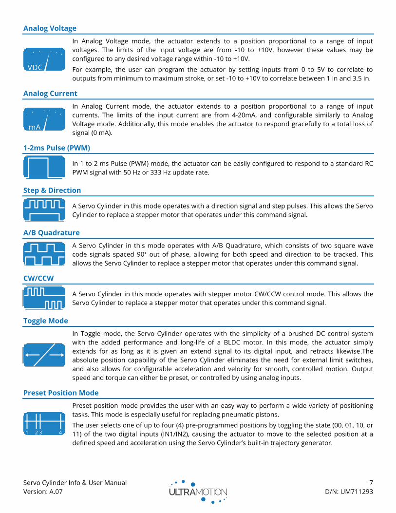
Analog Voltage
In Analog Voltage mode, the actuator extends to a position proportional to a range of input
voltages. The limits of the input voltage are from -10 to +10V, however these values may be
configured to any desired voltage range within -10 to +10V.
For example, the user can program the actuator by setting inputs from 0 to 5V to correlate to
outputs from minimum to maximum stroke, or set -10 to +10V to correlate between 1 in and 3.5 in.
Analog Current
In Analog Current mode, the actuator extends to a position proportional to a range of input
currents. The limits of the input current are from 4-20mA, and configurable similarly to Analog
Voltage mode. Additionally, this mode enables the actuator to respond gracefully to a total loss of
signal (0 mA).
1-2ms Pulse (PWM)
In 1 to 2 ms Pulse (PWM) mode, the actuator can be easily configured to respond to a standard RC
PWM signal with 50 Hz or 333 Hz update rate.
Step & Direction
A Servo Cylinder in this mode operates with a direction signal and step pulses. This allows the Servo
Cylinder to replace a stepper motor that operates under this command signal.
A/B Quadrature
A Servo Cylinder in this mode operates with A/B Quadrature, which consists of two square wave
code signals spaced 90° out of phase, allowing for both speed and direction to be tracked. This
allows the Servo Cylinder to replace a stepper motor that operates under this command signal.
CW/CCW
A Servo Cylinder in this mode operates with stepper motor CW/CCW control mode. This allows the
Servo Cylinder to replace a stepper motor that operates under this command signal.
Toggle Mode
In Toggle mode, the Servo Cylinder operates with the simplicity of a brushed DC control system
with the added performance and long-life of a BLDC motor. In this mode, the actuator simply
extends for as long as it is given an extend signal to its digital input, and retracts likewise.The
absolute position capability of the Servo Cylinder eliminates the need for external limit switches,
and also allows for configurable acceleration and velocity for smooth, controlled motion. Output
speed and torque can either be preset, or controlled by using analog inputs.
Preset Position Mode
Preset position mode provides the user with an easy way to perform a wide variety of positioning
tasks. This mode is especially useful for replacing pneumatic pistons.
The user selects one of up to four (4) pre-programmed positions by toggling the state (00, 01, 10, or
11) of the two digital inputs (IN1/IN2), causing the actuator to move to the selected position at a
defined speed and acceleration using the Servo Cylinder’s built-in trajectory generator.
Servo Cylinder Info & User Manual 8
Version: A.07 D/N: UM711293
Integrated Field-Oriented (FOC) Motor Control System with Phase Index™ Feedback
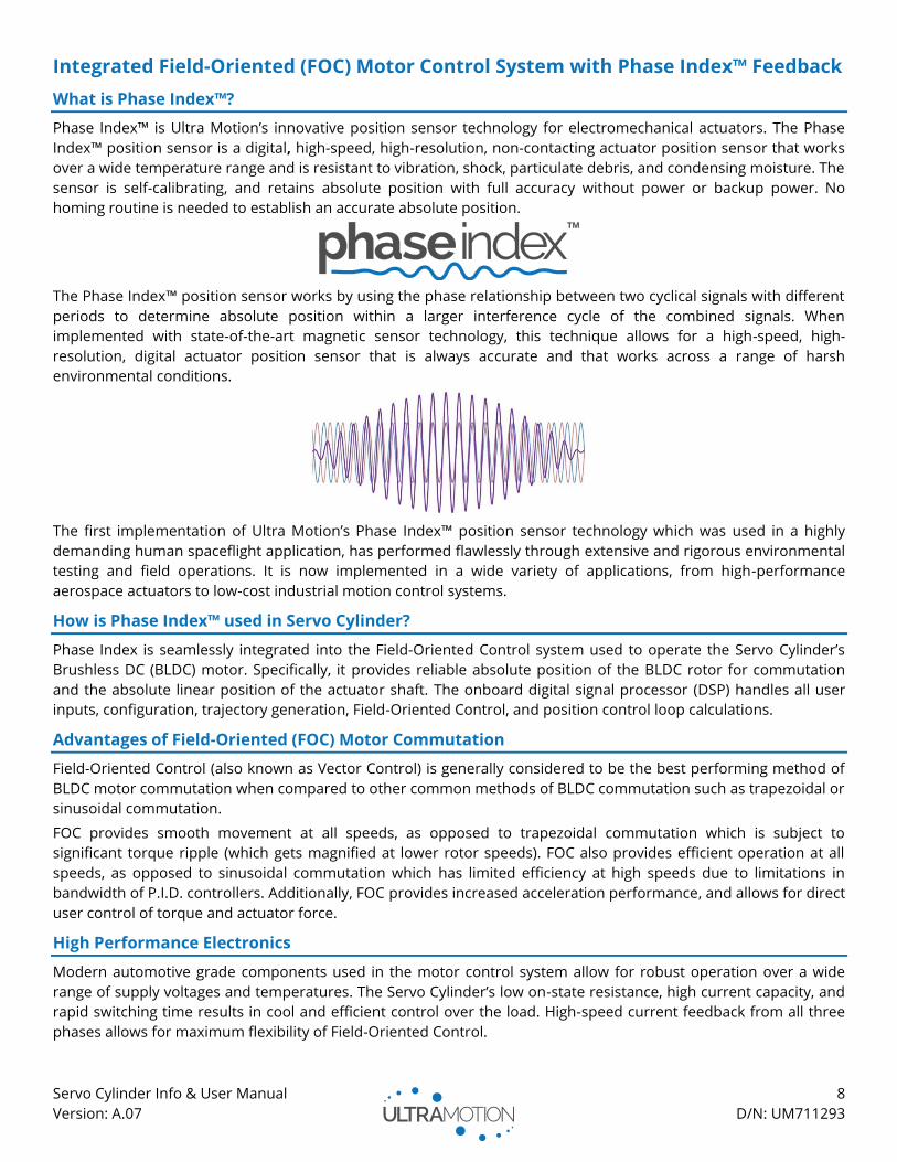
What is Phase Index™?
Phase Index™ is Ultra Motion’s innovative position sensor technology for electromechanical actuators. The Phase
Index™ position sensor is a digital, high-speed, high-resolution, non-contacting actuator position sensor that works
over a wide temperature range and is resistant to vibration, shock, particulate debris, and condensing moisture. The
sensor is self-calibrating, and retains absolute position with full accuracy without power or backup power. No
homing routine is needed to establish an accurate absolute position.
The Phase Index™ position sensor works by using the phase relationship between two cyclical signals with different
periods to determine absolute position within a larger interference cycle of the combined signals. When
implemented with state-of-the-art magnetic sensor technology, this technique allows for a high-speed, high-
resolution, digital actuator position sensor that is always accurate and that works across a range of harsh
environmental conditions.
The first implementation of Ultra Motion’s Phase Index™ position sensor technology which was used in a highly
demanding human spaceflight application, has performed flawlessly through extensive and rigorous environmental
testing and field operations. It is now implemented in a wide variety of applications, from high-performance
aerospace actuators to low-cost industrial motion control systems.
How is Phase Index™ used in Servo Cylinder?
Phase Index is seamlessly integrated into the Field-Oriented Control system used to operate the Servo Cylinder’s
Brushless DC (BLDC) motor. Specifically, it provides reliable absolute position of the BLDC rotor for commutation
and the absolute linear position of the actuator shaft. The onboard digital signal processor (DSP) handles all user
inputs, configuration, trajectory generation, Field-Oriented Control, and position control loop calculations.
Advantages of Field-Oriented (FOC) Motor Commutation
Field-Oriented Control (also known as Vector Control) is generally considered to be the best performing method of
BLDC motor commutation when compared to other common methods of BLDC commutation such as trapezoidal or
sinusoidal commutation.
FOC provides smooth movement at all speeds, as opposed to trapezoidal commutation which is subject to
significant torque ripple (which gets magnified at lower rotor speeds). FOC also provides efficient operation at all
speeds, as opposed to sinusoidal commutation which has limited efficiency at high speeds due to limitations in
bandwidth of P.I.D. controllers. Additionally, FOC provides increased acceleration performance, and allows for direct
user control of torque and actuator force.
High Performance Electronics
Modern automotive grade components used in the motor control system allow for robust operation over a wide
range of supply voltages and temperatures. The Servo Cylinder’s low on-state resistance, high current capacity, and
rapid switching time results in cool and efficient control over the load. High-speed current feedback from all three
phases allows for maximum flexibility of Field-Oriented Control.
Servo Cylinder Info & User Manual 9
Version: A.07 D/N: UM711293
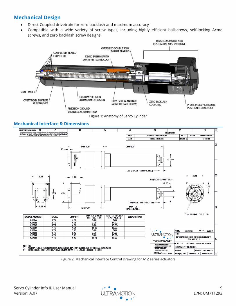
Mechanical Design
• Direct-Coupled drivetrain for zero backlash and maximum accuracy
• Compatible with a wide variety of screw types, including highly efficient ballscrews, self-locking Acme
screws, and zero backlash screw designs
Figure 1: Anatomy of Servo Cylinder
Mechanical Interface & Dimensions
Figure 2: Mechanical Interface Control Drawing for A1Z series actuators
Servo Cylinder Info & User Manual 10
Version: A.07 D/N: UM711293
Design Guidelines and Best Practices for Electromechanical Actuators
This section aims to provide some helpful advice for implementing Servo Cylinder and electromechanical linear
actuators in general. The information on this page will help get the most out of your Servo Cylinder while also
avoiding the most common pitfalls seen by the application engineers at Ultra Motion.
Include Dynamic Forces in Specified Load Rating
If using an actuator to lift a specific amount of weight,
remember that the forces being exerted by the
actuator will be in excess of that weight, due the
dynamic force required to accelerate the mass.
Would a “Self-Locking” actuator be better for you?
“Self-Locking” is a characteristic of a screw system
where the thread pitch and friction force is such that
no amount of actuator load will cause the screw to
rotate. This characteristic is due to friction force
exceeding screw torque and is utilized in machine
screws and in linear actuators for certain applications.
An actuator powered by a self-locking leadscrew has
the following performance tradeoffs:
Pros Cons
• No power necessary
to statically support
a large load
indefinitely.
• Lower Cost
(For Acme screws).
• Generally lower
performance: Lower
force, max speed, and
efficiency.
• Increased stiction, micro-
motions more difficult to
achieve
Increase Maximum Speed with a Higher Bus Voltage
In DC motors, torque/force is independent of bus
voltage. However, maximum actuator speed is
proportional to bus voltage.
Use an Unregulated Power Supply if Possible
For the reasons outlined in Power Supply
Requirements and Wiring Details (Page 13),
unregulated supplies are generally superior to
regulated supplies for motion control applications.
Motor Back-EMF Causes Unstable Bus Voltage
For the reasons outlined in Back-EMF (Voltage Spikes)
(Page 13), motors will inject energy into a power bus
and cause spikes in bus voltage. Use a Power Shunt
(Page 13), and be wary of any equipment that shares
a power bus with an actuator.
Shield All Signal Inputs and Outputs
Wires leading to the actuator (especially analog inputs
and GPIOs) should be shielded to prevent
electromagnetic interference (EMI) and cross-talk.
This is the most common cause for unexpected
behavior in Proportional mode.
Never “Side-Load” an Actuator Not Rated For Side-Load
Side loads often occur inadvertently by over-
constrained actuator mount points. Rod style linear
actuators such as Servo Cylinder are typically not
rated for “side-load” (force which is perpendicular to
the direction of travel of the shaft). Side-loads result
in sharply accelerated wear. We suggest mounting
methods which have rotational degrees of freedom
such as pivoting joints (like a clevis or trunnion), even
if rotation is not expected during operation.
Beware Running an Actuator into a Hard-Stop
When using an actuator with a DC motor, take care
that you do not run the actuator into a physical “hard-
stop”, such as a machine element or any physical
body which the actuator impacts on its travel and
which disallows movement. If this happens, the
control system will attempt to obey position
commands by powering through the physical block.
Often, this results in the motor over-heating and
burning out.
Servo Cylinder is programmed to prevent collision
with its own internal hard-stops, however care must
be taken to protect the actuator from external hard-
stops. It also features errMode – Error Mode (Actuator
Hardware Protection Feature) which will prevent the
actuator from exerting damaging amounts of force or
torque. This is especially useful when training and
testing out an application.
Servo Cylinder Info & User Manual 11
Version: A.07 D/N: UM711293
Requirements and Specifications
This section contains all information about the electrical and mechanical specifications and requirements of the
Servo Cylinder actuator.
Mechanical Performance
Since there are a wide variety of different Servo Cylinder models with various performance characteristics, refer to
the Servo Cylinder Datasheet for information that pertains to your specific actuator. If you do not yet have your
datasheet, it will be automatically generated by completing the Servo Cylinder Configurator on the Ultra Motion
website. Each datasheet includes:
• Max Load vs. Speed (Continuous and Peak)
• Actuator life vs Load (for Ballscrew Models)
• PV Limits (for Acme Screw Models)
• Mechanical Interface Control Drawing (ICD) for the specific actuator model
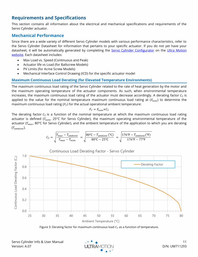
Maximum Continuous Load Derating (for Elevated Temperature Environments)
The maximum continuous load rating of the Servo Cylinder related to the rate of heat generation by the motor and
the maximum operating temperature of the actuator components. As such, when environmental temperature
increases, the maximum continuous load rating of the actuator must decrease accordingly. A derating factor 𝐶𝑇 is
applied to the value for the nominal temperature maximum continuous load rating at (𝐹𝑛𝑜𝑚) to determine the
maximum continuous load rating (𝐹𝑇) for the actual operational ambient temperature:
𝐹𝑇 = 𝐹𝑛𝑜𝑚×𝐶𝑇
The derating factor 𝐶𝑇 is a function of the nominal temperature at which the maximum continuous load rating
actuator is defined (𝑇𝑛𝑜𝑚, 25°C for Servo Cylinder), the maximum operating environmental temperature of the
actuator (𝑇𝑚𝑎𝑥 , 80°C for Servo Cylinder), and the ambient temperature of the application to which you are derating
(𝑇𝑎𝑚𝑏𝑖𝑒𝑛𝑡).
𝐶𝑇 = √𝑇𝑚𝑎𝑥 − 𝑇𝑎𝑚𝑏𝑖𝑒𝑛𝑡
𝑇𝑚𝑎𝑥 − 𝑇𝑛𝑜𝑚
= √80℃ − 𝑇𝑎𝑚𝑏𝑖𝑒𝑛𝑡 (℃)
80℃ − 25℃ = √
176℉ − 𝑇𝑎𝑚𝑏𝑖𝑒𝑛𝑡(℉)
176℉ − 77℉
Figure 3: Derating factor for maximum continuous load 𝐶𝑇 as a function of temperature.
0.0
0.2
0.4
0.6
0.8
1.0
25 30 35 40 45 50 55 60 65 70 75 80
Co
nti
nu
ou
s Lo
ad
Dera
tin
g F
act
or
(CT)
Ambient Temperature [°C]
Continuous Load Derating Factor - Servo Cylinder
Derating Factor
Servo Cylinder Info & User Manual 12
Version: A.07 D/N: UM711293
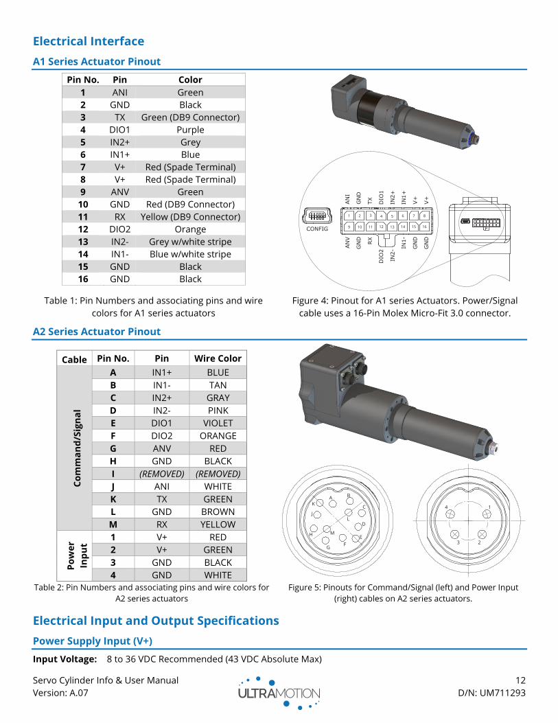
Electrical Interface
A1 Series Actuator Pinout
Pin No. Pin Color
1 ANI Green
2 GND Black
3 TX Green (DB9 Connector)
4 DIO1 Purple
5 IN2+ Grey
6 IN1+ Blue
7 V+ Red (Spade Terminal)
8 V+ Red (Spade Terminal)
9 ANV Green
10 GND Red (DB9 Connector)
11 RX Yellow (DB9 Connector)
12 DIO2 Orange
13 IN2- Grey w/white stripe
14 IN1- Blue w/white stripe
15 GND Black
16 GND Black
Table 1: Pin Numbers and associating pins and wire
colors for A1 series actuators
Figure 4: Pinout for A1 series Actuators. Power/Signal
cable uses a 16-Pin Molex Micro-Fit 3.0 connector.
A2 Series Actuator Pinout
Cable Pin No. Pin Wire Color
Co
mm
an
d/S
ign
al
A IN1+ BLUE
B IN1- TAN
C IN2+ GRAY
D IN2- PINK
E DIO1 VIOLET
F DIO2 ORANGE
G ANV RED
H GND BLACK
I (REMOVED) (REMOVED)
J ANI WHITE
K TX GREEN
L GND BROWN
M RX YELLOW
Po
we
r
Inp
ut
1 V+ RED
2 V+ GREEN
3 GND BLACK
4 GND WHITE
Table 2: Pin Numbers and associating pins and wire colors for
A2 series actuators Figure 5: Pinouts for Command/Signal (left) and Power Input
(right) cables on A2 series actuators.
Electrical Input and Output Specifications
Power Supply Input (V+)
Input Voltage: 8 to 36 VDC Recommended (43 VDC Absolute Max)
Servo Cylinder Info & User Manual 13
Version: A.07 D/N: UM711293
Ground: 2x GND (High current, two (2) grounding pins required)
Max Current: See product datasheets for continuous and peak current ratings for your model.
Refer to Power Supply Requirements and Wiring Details below for recommendations.
WARNING: Controller electronics will be damaged if your bus voltage ever exceeds 50 VDC. Note that this
includes voltage spikes due to self-induced Back-EMF.
WARNING: Read section about Back-EMF to completely understand voltage spikes before operating.
WARNING: Do not reverse polarity on the power input. If poles are reversed, internal protection circuitry will
result in the two poles being shorted, potentially causing damage to the PSU.
WARNING: Never “Hot Plug” or connect/disconnect power to the servo cylinder until all wiring and
connectors are in place.
Back-EMF (Voltage Spikes) and Back-Driving
During normal operation it is common to see fluctuations or spikes in your power bus voltage which are the result
of voltage draws and regenerations from the motor. The most likely drivers of severe voltage spikes are:
1. Rapid acceleration and deceleration
2. Back-driving the actuator. Back-driving occurs when the actuator has sufficient load applied to it to move
the shaft and spin the motor. A scenario in which this might occur is if a non-self-locking actuator is lifting a
mass in vertical direction while electrical power is lost, causing the lifted weight to force down on the
actuator shaft, resulting in back-driving.
The Servo Cylinder has an automatic dynamic braking feature that will attempt to clip voltage spikes at 44VDC.
When this happens, the energy is dissipated in the motor windings as heat. When this feature engages, you will
notice the actuator stutter as the feature flutters on and off. If normal operation results in this feature engaging, we
strongly recommend you remedy the issue by adding a Power Shunt to your system or using an Ultra Motion PS-1X
series Power Supply Unit.
Power Shunt
A Power Shunt, such as the Ultra Motion Power Shunt, is a type of Over-Voltage Protection (OVP) device. They
protect a power bus by engaging at a predefined voltage level and dissipating energy across a high-power shunt
resistor until voltage is restored to nominal levels. This protects the Servo Cylinder and other equipment on the
same power bus from damage due to excessive voltage spikes and back-EMF. The use of a power shunt is always
recommended for safety, but especially important in the following situations:
• Applications which require hard/fast acceleration and deceleration.
• Applications where the load is assisting the actuator’s motion (spring, gravity in a vertical application, etc.).
• Applications which require the use of a regulated power system.
• Applications where the actuator must share a power bus with other sensitive equipment.
Power shunts must be wired in parallel with the output of the DC power supply. In order to be effective, power
shunts must maintain connectivity to the actuator in the event of a loss of power, blown fuse, or engaged
Emergency Power-Off (EPO) switch. See Figure 6: Power Wiring Diagram.
NOTE: A power shunt is not necessary when using an Ultra Motion PS-1X series PSU, which has integrated OVP.
Power Supply Requirements and Wiring Details
Voltage Rating: 8-36 VDC Recommended (43VDC Absolute Max)
Power rating: 180-200W, smaller supplies are suitable for less demanding applications
We strongly recommend using an Ultra Motion PS-1X series Power Supply Unit to power Servo Cylinder. The PS-1X
Series PSUs have been specifically designed for use with Servo Cylinder and other intensive motion control
applications. Benefits of the PS-1X Series PSUs over other PSUs include:
• Unregulated power conversion (greatly preferred over regulated for motion control applications, see below).
• Integrated Over-Voltage Protection (OVP) device eliminates the need for a power shunt.

Servo Cylinder Info & User Manual 14
Version: A.07 D/N: UM711293
• High Voltage (36 VDC), gets highest speed performance out of Servo Cylinder.
• High-efficiency regenerating supply, >80% efficient at draws 10-100% of capacity, quiescent power <5 W.
• AC- and DC-side fuses: DC-side fuse isolates the capacitor when blown, removing need for external fuse.
• Robust design, dust resistant (IP50), EPO Ready, all in integrated package.
A third-party PSU or existing power system may also be used if it meets the power supply requirements. When
considering power systems, take into consideration the tradeoffs of regulated vs unregulated power supplies:
• Unregulated Power Supplies (Preferred): An unregulated power supply is preferred for servo applications
because of its ability to supply bursts of energy during acceleration, and its ability to absorb energy during
deceleration/back-driving events. The large smoothing capacitor of a properly sized unregulated supply
maintains safe actuator voltage levels when absorbing/supplying large amounts of electrical energy. The use
of an unregulated power supply reduces but does not eliminate the need for a power shunt.
• Regulated Power Supplies: Many popular benchtop power supplies are regulated, which is acceptable for
applications that don’t require high accelerations and cannot be back-driven. Regulated power supplies
cannot absorb the energy created during deceleration or back-driving events as effectively as unregulated
supplies, which can cause the supply voltage to quickly rise to unsafe levels. The power supply can also fall
below required voltage levels due to high current demands during acceleration or high force events. A
power shunt can reduce the risk of over-voltage in a regulated power supply system.
The power system should also have following safety features, shown in the circuit below:
• Emergency Power-Off (EPO) switch: Generally this is a “push-lock” type NC switch or relay which serves the
purpose of immediately removing power from the system. An AC power cut-off is generally inadequate for
rapidly removing power to the actuator due to stored energy in power supply capacitors.
• External Fuse: A slow burning fuse should be used on the positive leg of the DC power supply to isolate the
Servo Cylinder from the DC power stored in capacitors in an overloading condition.
• Power Shunt: A power shunt, described above, must not be isolated by a blown fuse or EPO switch.
The Ultra Motion Power Supply Unit is has an integrated power shunt, fuse, and is EPO switch ready. Please ensure
you have properly designed your power system and addressed all safety concerns.
Figure 6: Power Wiring Diagrams. The top circuit is a diagram of an adequate power supply setup, featuring a fuse, and
Emergency Power-Off (EPO) switch, and power shunt. The bottom circuit is an Ultra Motion Power Supply Unit configuration.
Analog Current Input (ANI)
Input Current Range: 4-20mA (adjustable to range within 4-20mA in configuration file)
Ground: Any GND
Used for Proportional Mode with Current Control and for proportional speed control in toggle mode.
Care should be taken to ensure analog signals are properly shielded against EMI, and are routed separately from
power wires and other sources of interference. When possible, a 100% foil shield should be used and the shield
electrically connected to chassis ground.
Ultra Motion
Power Shunt
+-
Servo Cylinder
GND
V+Power Supply
8-36VDC
180-200W
V+
GND
FUSE EPO
Ultra Motion
Power Supply Unit
PS-1X Series
EPO OUT
EPO IN
+
-
Servo Cylinder
GND
V+
EPO
Servo Cylinder Info & User Manual 15
Version: A.07 D/N: UM711293
Analog Voltage Input (ANV)
Input Voltage Range: -10 to +10 VDC (adjustable to range within -10 to +10 VDC in configuration file).
Ground: Any GND
Used for Proportional Mode with Voltage Control and for proportional speed control in toggle mode. Ground to any
GND. Care should be taken to ensure analog signals are properly shielded against EMI, and are routed separately
from power wires and other sources of interference. When possible, a 100% foil shield should be used and the
shield electrically connected to ground.
Optically Isolated Digital Inputs (IN1+, IN1-, IN2+, and IN2-)
Input
Voltage:
3.3 to 7 VDC, or more when using an appropriate current limiting resistor (R). See Powering the
Optically Isolated Digital Inputs (IN1+, IN1-, IN2+, and IN2-) below
Ground: Use isolated grounds for optimal noise mitigation. Actuator ground can be used for IN1- or IN2-, but
this does not provide complete isolation.
Used for Proportional Mode (with 1 to 2 ms Pulse Control), Preset Position Mode, All Incremental Modes.
WARNING: Damage will occur if voltage exceeds 7 VDC without a current limiting resistor (R). See Powering
the Optically Isolated Digital Inputs (IN1+, IN1-, IN2+, and IN2-) below
The Servo Cylinder has two dedicated, optically isolated digital inputs, IN1 and IN2. An opto-isolator transmits an
electrical signal between two electrically isolated circuits via a light emitting diode and photodiode pair. The use of
optically isolated inputs allow for high data transfer rates, protection from high voltages, and superior noise
rejection.
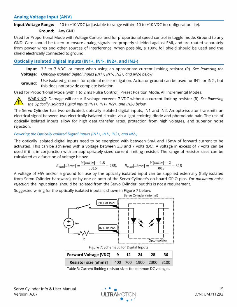
Powering the Optically Isolated Digital Inputs (IN1+, IN1-, IN2+, and IN2-)
The optically isolated digital inputs need to be energized with between 5mA and 15mA of forward current to be
activated. This can be achieved with a voltage between 3.3 and 7 volts (DC). A voltage in excess of 7 volts can be
used if it is in conjunction with an appropriately sized current limiting resistor. The range of resistor sizes can be
calculated as a function of voltage below:
𝑅𝑚𝑖𝑛[𝑜ℎ𝑚𝑠] =𝑉[𝑣𝑜𝑙𝑡𝑠] − 1.8
. 015− 285, 𝑅𝑚𝑎𝑥[𝑜ℎ𝑚𝑠] =
𝑉[𝑣𝑜𝑙𝑡𝑠] − 2
. 005− 315
A voltage of +5V and/or a ground for use by the optically isolated input can be supplied externally (fully isolated
from Servo Cylinder hardware), or by one or both of the Servo Cylinder’s on-board GPIO pins. For maximum noise
rejection, the input signal should be isolated from the Servo Cylinder, but this is not a requirement.
Suggested wiring for the optically isolated inputs is shown in Figure 7 below.
Figure 7: Schematic for Digital Inputs
Forward Voltage [VDC] 9 12 24 28 36
Resistor size [ohms] 400 700 1900 2300 3100
Table 3: Current limiting resistor sizes for common DC voltages.
V+
R
Servo Cylinder (Internal)
IN1+ or IN2+
IN1- or IN2-
Opto-Isolator
Servo Cylinder Info & User Manual 16
Version: A.07 D/N: UM711293
RS232 Serial Input (TX and RX)
Baud Rate: 2400 to 256,000
The serial connection to the actuator uses the RS232 protocol. If the device you are connecting the Servo Cylinder
to does not have a standard serial port, you can use any standard USB-to-Serial converter (such as an FTDI
converter).
General Purpose Input/Outputs (GPIOs) (DIO1 and DIO2)
Input Voltage Range: 0 to 5 VDC
The Servo Cylinder has two (2) GPIO pins which can be used for a wide variety of tasks
WARNING: Damage will occur if input voltage exceeds 5 VDC or if 5 VDC output is shorted to GND
The GPIO pins can be configured to be used as a high impedance digital input, or to output any of the following:
• +5 VDC supply (up to 250 mA)
• Ground (sink up to 250 mA)
• 1kHz PWM waveform proportional to
a variable set by ioPWM1
o Output variables include
position, velocity, force, or
bus voltage
• Limit switch signals (Triggers at specified travel distances)
• Output the result of the masked status register (1 kHz
refresh rate)
o The GPIO pin will output a digital signal depending
on the result of the Servo Cylinder’s status word
masked with a user defined bit mask. See “Status
Word Description” for more information.
It is important to note that DIO1 and DIO2 are NOT optically isolated, meaning that they may be more prone to
inject inadvertent noise into the system. They are capable of sinking or sourcing current to drive an external lamp,
switch, etc.
See Configuring General Purpose Input / Outputs on Page 32 for details on setting up these inputs.
Cabling
To use the Servo Cylinder, you will need a USB mini B cable (For configuration). In addition, you need Power &
Communication Cables to interface with the actuator. The A1 and A2 series have differing Power & Communication
Cable types.
• A1 Series: The A1 series actuators use a single Power & Communication Cable that terminates with a
Molex Micro-Fit 3.0™ type connector. This cable carries both the power and communications signals in a
single harness. Read the below sections to learn how to purchase a cable appropriate for your application.
• A2 Series: The A2 series (IP-65) rated actuators have separate cable assemblies for power and
communications. Each cable comes with an environmentally sealed connector, and with all conductors
populated, and with flying (pigtail) leads on the opposite end. Note that the connector receptacle on the
actuator must have the mating plug or cap tightened to 1.5 Nm in order to be IP65.
Purchasing Cables from Ultra Motion
Select a USB cable, as well as a Power & Communications Cable appropriate to your actuator series
USB Cable
Use part number CBL-USB to purchase USB Mini B 6ft cable.
Servo Cylinder Info & User Manual 17
Version: A.07 D/N: UM711293
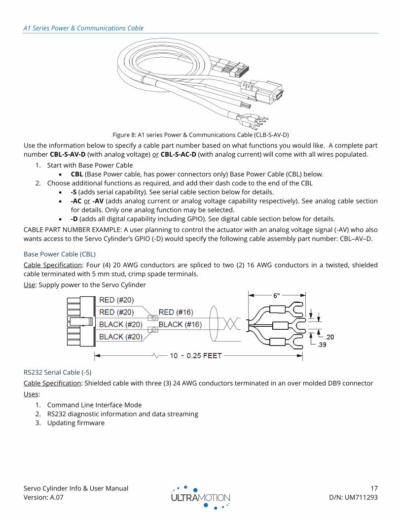
A1 Series Power & Communications Cable
Figure 8: A1 series Power & Communications Cable (CLB-S-AV-D)
Use the information below to specify a cable part number based on what functions you would like. A complete part
number CBL-S-AV-D (with analog voltage) or CBL-S-AC-D (with analog current) will come with all wires populated.
1. Start with Base Power Cable
• CBL (Base Power cable, has power connectors only) Base Power Cable (CBL) below.
2. Choose additional functions as required, and add their dash code to the end of the CBL
• -S (adds serial capability). See serial cable section below for details.
• -AC or -AV (adds analog current or analog voltage capability respectively). See analog cable section
for details. Only one analog function may be selected.
• -D (adds all digital capability including GPIO). See digital cable section below for details.
CABLE PART NUMBER EXAMPLE: A user planning to control the actuator with an analog voltage signal (-AV) who also
wants access to the Servo Cylinder’s GPIO (-D) would specify the following cable assembly part number: CBL–AV–D.
Base Power Cable (CBL)
Cable Specification: Four (4) 20 AWG conductors are spliced to two (2) 16 AWG conductors in a twisted, shielded
cable terminated with 5 mm stud, crimp spade terminals.
Use: Supply power to the Servo Cylinder
RS232 Serial Cable (-S)
Cable Specification: Shielded cable with three (3) 24 AWG conductors terminated in an over molded DB9 connector
Uses:
1. Command Line Interface Mode
2. RS232 diagnostic information and data streaming
3. Updating firmware

Servo Cylinder Info & User Manual 18
Version: A.07 D/N: UM711293
Analog Voltage Cable (-AV)
Cable Specification: Two (2) 22 AWG conductors in a shielded twisted pair terminated with 6” flying leads.
Uses:
1. -10V to +10V Proportional Input Mode
2. Toggle Mode with -10V to +10V control of speed or force
Analog Current Cable (-AC)
Cable Specification: Two (2) 22 AWG conductors in a shielded twisted pair terminated with 6” flying leads.
Uses:
1. 4-20mA Proportional Input Mode
2. Toggle Mode with 4-20mA control of speed or force
Digital Cable (-D)
Cable Specification: Six (6) 22 AWG conductors in a shielded cable, terminated with 6” flying leads.
Uses:
1. 1 to 2 ms Pulse Proportional Input Mode
2. Incremental Modes
3. Four Preset Position Mode
4. Toggle Mode
5. General Purpose Input/Output (GPIO) functionality
Servo Cylinder Info & User Manual 19
Version: A.07 D/N: UM711293
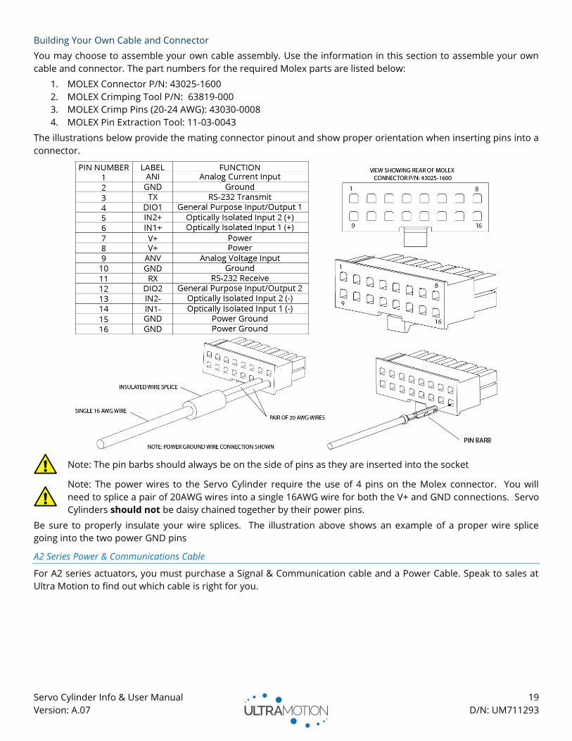
Building Your Own Cable and Connector
You may choose to assemble your own cable assembly. Use the information in this section to assemble your own
cable and connector. The part numbers for the required Molex parts are listed below:
1. MOLEX Connector P/N: 43025-1600
2. MOLEX Crimping Tool P/N: 63819-000
3. MOLEX Crimp Pins (20-24 AWG): 43030-0008
4. MOLEX Pin Extraction Tool: 11-03-0043
The illustrations below provide the mating connector pinout and show proper orientation when inserting pins into a
connector.
Note: The pin barbs should always be on the side of pins as they are inserted into the socket
Note: The power wires to the Servo Cylinder require the use of 4 pins on the Molex connector. You will
need to splice a pair of 20AWG wires into a single 16AWG wire for both the V+ and GND connections. Servo
Cylinders should not be daisy chained together by their power pins.
Be sure to properly insulate your wire splices. The illustration above shows an example of a proper wire splice
going into the two power GND pins
A2 Series Power & Communications Cable
For A2 series actuators, you must purchase a Signal & Communication cable and a Power Cable. Speak to sales at
Ultra Motion to find out which cable is right for you.

Servo Cylinder Info & User Manual 20
Version: A.07 D/N: UM711293
Initial Setup
This section will cover how to start set up the Servo Cylinder, and power it for the first time.
Getting Started
You must determine what control mode you wish to operate in before getting started. You must provide the Servo
Cylinder with power and a compatible command signal. If you need assistance in determining which control mode
is right for your application, please contact one of our application engineers or review the control modes section.
You will need:
• Servo Cylinder (A-series) Actuator
• Command/Signal Cable (Combined with Power Input Cable for A1-series actuators)
• Power Input Cable (Combined with Command/Signal Cable for A1-series actuators)
• Mini-USB Cable (only if configuring using USB Mass-Storage)
• Power Supply Unit (PSU) capable of 8-36 VDC (≥180 W suggested, see PS-1X Series PSUs)
• A method of issuing a command signal (Such as RS232 signal, 4-20mA current, voltage, stepper, etc.)
Setting up the Servo Cylinder Hardware
Note: Setting up A2-Series Servo Cylinders
A2 Servo Cylinders require additional setup and precautions to maintain IP65 integrity. Please see Additional Setup
Information for A2-Series Actuators on page 21 for more information.
WARNING: Never “Hot Plug” or power the Servo Cylinder until all wiring and connectors are in place.
Begin by connecting all of the wires and cables first, and then turning on the power. To do this:
1. Connect the Power Input and Command/Signal Cable to the Servo Cylinder. If using an A2-Series Servo
Cylinder, read Additional Setup Information for A2-Series Actuators on page 21.
2. Ensure the Power Supply is off, and then connect the Power Input Cable to the Power Supply.
3. Connect the Command/Signal cable to the system that will be issuing serial commands (in this example, we
will connect to a Windows 7 PC with an RS232-to-USB Converter).
4. (If configuring using USB Mass-Storage) Connect the Mini-USB cable between the Servo Cylinder and your
computer. If using an A2-Series Servo Cylinder, read Additional Setup Information for A2-Series Actuators on
page 21.
5. Turn on the Power Supply.
Servo Cylinder Info & User Manual 21
Version: A.07 D/N: UM711293
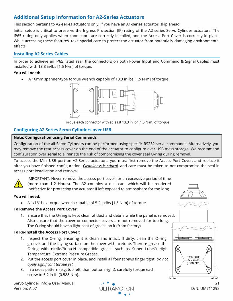
Additional Setup Information for A2-Series Actuators
This section pertains to A2-series actuators only. If you have an A1-series actuator, skip ahead
Initial setup is critical to preserve the Ingress Protection (IP) rating of the A2 series Servo Cylinder actuators. The
IP65 rating only applies when connectors are correctly installed, and the Access Port Cover is correctly in place.
While accessing these features, take special care to protect the actuator from potentially damaging environmental
effects.
Installing A2 Series Cables
In order to achieve an IP65 rated seal, the connectors on both Power Input and Command & Signal Cables must
installed with 13.3 in·lbs [1.5 N·m] of torque.
You will need:
• A 16mm spanner-type torque wrench capable of 13.3 in·lbs [1.5 N·m] of torque.
Torque each connector with at least 13.3 in lbf [1.5 N·m] of torque
Configuring A2 Series Servo Cylinders over USB
Note: Configuration using Serial Commands
Configuration of the all Servo Cylinders can be performed using specific RS232 serial commands. Alternatively, you
may remove the rear access cover on the end of the actuator to configure over USB mass storage. We recommend
configuration over serial to eliminate the risk of compromising the cover seal O-ring during removal.
To access the Mini-USB port on A2-Series actuators, you must first remove the Access Port Cover, and replace it
after you have finished configuration. Cleanliness is critical, and care must be taken to not compromise the seal in
access port installation and removal.
IMPORTANT: Never remove the access port cover for an excessive period of time
(more than 1-2 Hours). The A2 contains a desiccant which will be rendered
ineffective for protecting the actuator if left exposed to atmosphere for too long.
You will need:
• A 1/16” hex torque wrench capable of 5.2 in·lbs [1.5 N·m] of torque
To Remove the Access Port Cover:
1. Ensure that the O-ring is kept clean of dust and debris while the panel is removed.
Also ensure that the cover or connector covers are not removed for too long.
The O-ring should have a light coat of grease on it (from factory).
To Re-Install the Access Port Cover:
1. Inspect the O-ring, ensuring it is clean and intact. If dirty, clean the O-ring,
groove, and the faying surface on the cover with acetone. Then re-grease the
O-ring with nitrile/Buna-N compatible grease such as Super Lube® High
Temperature, Extreme Pressure Grease.
2. Put the access port cover in place, and install all four screws finger tight. Do not
apply significant torque yet.
3. In a cross pattern (e.g. top left, than bottom right), carefully torque each
screw to 5.2 in-lb [0.588 Nm].
Servo Cylinder Info & User Manual 22
Version: A.07 D/N: UM711293
Configuration
How to Configure with USB Mass Storage
The Servo Cylinder has a small 10kB section of non-volatile flash memory that is used to store configuration data.
Do not use this memory to store backup copies of CONFIG.TXT and HARDWARE.TXT. Storing any files other than
CONFIG.TXT and HARDWARE.TXT will exceed available storage space.
Note: HARDWARE.TXT and CONFIG.TXT must be present to operate
The Servo Cylinder’s microcontroller needs both HARDWARE.TXT and CONFIG.TXT to operate. Deleting, removing,
or renaming these files or deleting variables within the files will result in a fault mode. We recommend creating a
backup of these files to your local drive before starting to edit them. Do not back up on Servo Cylinder.
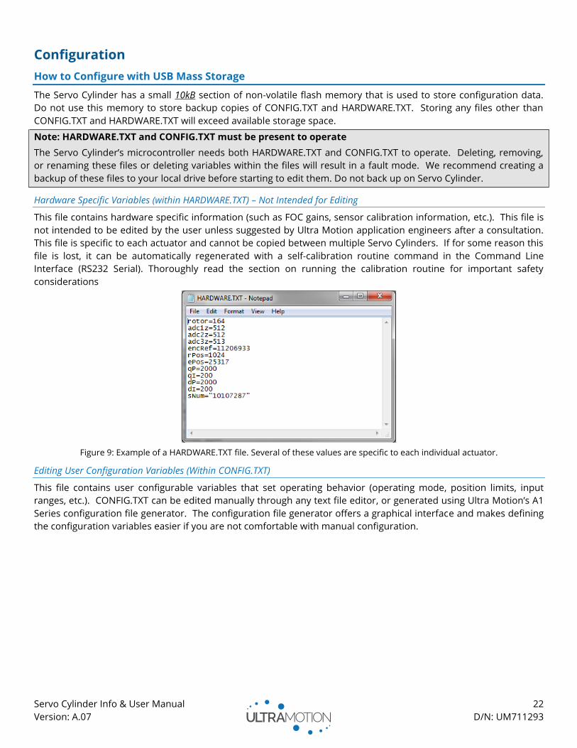
Hardware Specific Variables (within HARDWARE.TXT) – Not Intended for Editing
This file contains hardware specific information (such as FOC gains, sensor calibration information, etc.). This file is
not intended to be edited by the user unless suggested by Ultra Motion application engineers after a consultation.
This file is specific to each actuator and cannot be copied between multiple Servo Cylinders. If for some reason this
file is lost, it can be automatically regenerated with a self-calibration routine command in the Command Line
Interface (RS232 Serial). Thoroughly read the section on running the calibration routine for important safety
considerations
Figure 9: Example of a HARDWARE.TXT file. Several of these values are specific to each individual actuator.
Editing User Configuration Variables (Within CONFIG.TXT)
This file contains user configurable variables that set operating behavior (operating mode, position limits, input
ranges, etc.). CONFIG.TXT can be edited manually through any text file editor, or generated using Ultra Motion’s A1
Series configuration file generator. The configuration file generator offers a graphical interface and makes defining
the configuration variables easier if you are not comfortable with manual configuration.
Servo Cylinder Info & User Manual 23
Version: A.07 D/N: UM711293
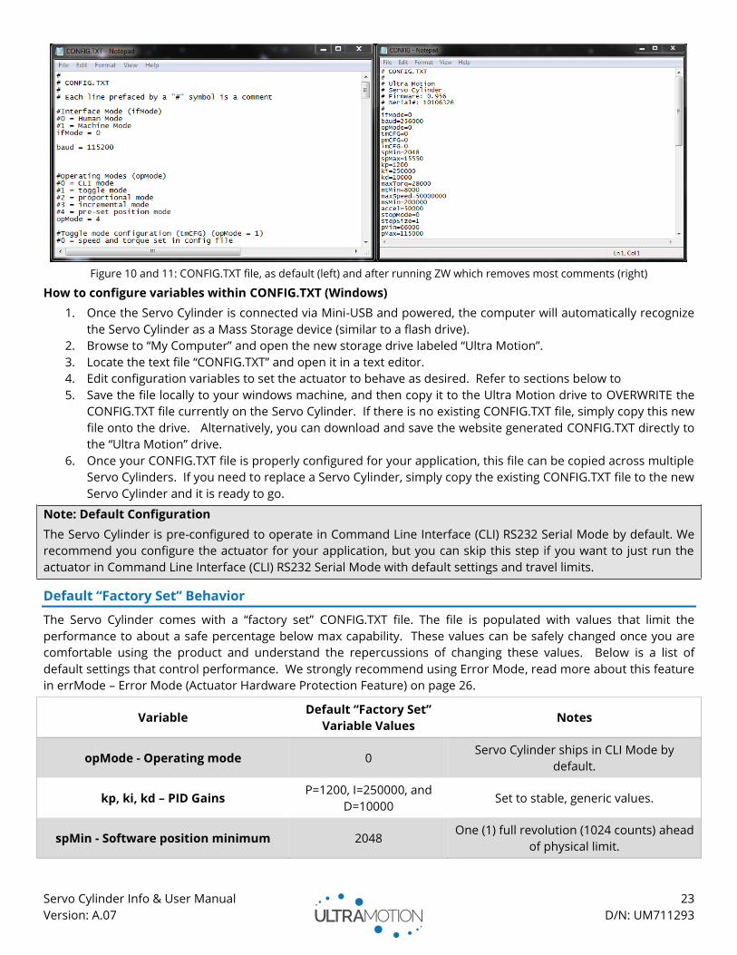
Figure 10 and 11: CONFIG.TXT file, as default (left) and after running ZW which removes most comments (right)
How to configure variables within CONFIG.TXT (Windows)
1. Once the Servo Cylinder is connected via Mini-USB and powered, the computer will automatically recognize
the Servo Cylinder as a Mass Storage device (similar to a flash drive).
2. Browse to “My Computer” and open the new storage drive labeled “Ultra Motion”.
3. Locate the text file “CONFIG.TXT” and open it in a text editor.
4. Edit configuration variables to set the actuator to behave as desired. Refer to sections below to
5. Save the file locally to your windows machine, and then copy it to the Ultra Motion drive to OVERWRITE the
CONFIG.TXT file currently on the Servo Cylinder. If there is no existing CONFIG.TXT file, simply copy this new
file onto the drive. Alternatively, you can download and save the website generated CONFIG.TXT directly to
the “Ultra Motion” drive.
6. Once your CONFIG.TXT file is properly configured for your application, this file can be copied across multiple
Servo Cylinders. If you need to replace a Servo Cylinder, simply copy the existing CONFIG.TXT file to the new
Servo Cylinder and it is ready to go.
Note: Default Configuration
The Servo Cylinder is pre-configured to operate in Command Line Interface (CLI) RS232 Serial Mode by default. We
recommend you configure the actuator for your application, but you can skip this step if you want to just run the
actuator in Command Line Interface (CLI) RS232 Serial Mode with default settings and travel limits.
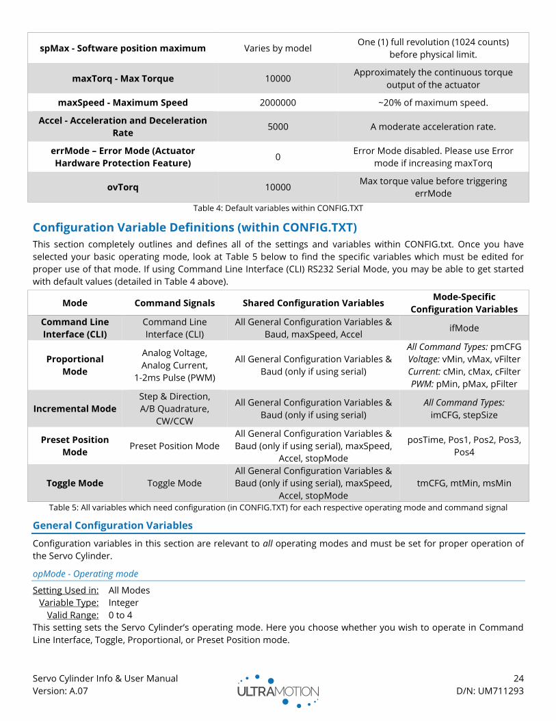
Default “Factory Set” Behavior
The Servo Cylinder comes with a “factory set” CONFIG.TXT file. The file is populated with values that limit the
performance to about a safe percentage below max capability. These values can be safely changed once you are
comfortable using the product and understand the repercussions of changing these values. Below is a list of
default settings that control performance. We strongly recommend using Error Mode, read more about this feature
in errMode – Error Mode (Actuator Hardware Protection Feature) on page 26.
Variable Default “Factory Set”
Variable Values Notes
opMode - Operating mode 0 Servo Cylinder ships in CLI Mode by
default.
kp, ki, kd – PID Gains P=1200, I=250000, and
D=10000 Set to stable, generic values.
spMin - Software position minimum 2048 One (1) full revolution (1024 counts) ahead
of physical limit.
Servo Cylinder Info & User Manual 24
Version: A.07 D/N: UM711293
spMax - Software position maximum Varies by model One (1) full revolution (1024 counts)
before physical limit.
maxTorq - Max Torque 10000 Approximately the continuous torque
output of the actuator
maxSpeed - Maximum Speed 2000000 ~20% of maximum speed.
Accel - Acceleration and Deceleration
Rate 5000 A moderate acceleration rate.
errMode – Error Mode (Actuator
Hardware Protection Feature) 0
Error Mode disabled. Please use Error
mode if increasing maxTorq
ovTorq 10000 Max torque value before triggering
errMode
Table 4: Default variables within CONFIG.TXT
Configuration Variable Definitions (within CONFIG.TXT)
This section completely outlines and defines all of the settings and variables within CONFIG.txt. Once you have
selected your basic operating mode, look at Table 5 below to find the specific variables which must be edited for
proper use of that mode. If using Command Line Interface (CLI) RS232 Serial Mode, you may be able to get started
with default values (detailed in Table 4 above).
Mode Command Signals Shared Configuration Variables Mode-Specific
Configuration Variables
Command Line
Interface (CLI)
Command Line
Interface (CLI)
All General Configuration Variables &
Baud, maxSpeed, Accel ifMode
Proportional
Mode
Analog Voltage,
Analog Current,
1-2ms Pulse (PWM)
All General Configuration Variables &
Baud (only if using serial)
All Command Types: pmCFG
Voltage: vMin, vMax, vFilter
Current: cMin, cMax, cFilter
PWM: pMin, pMax, pFilter
Incremental Mode
Step & Direction,
A/B Quadrature,
CW/CCW
All General Configuration Variables &
Baud (only if using serial)
All Command Types:
imCFG, stepSize
Preset Position
Mode Preset Position Mode
All General Configuration Variables &
Baud (only if using serial), maxSpeed,
Accel, stopMode
posTime, Pos1, Pos2, Pos3,
Pos4
Toggle Mode Toggle Mode
All General Configuration Variables &
Baud (only if using serial), maxSpeed,
Accel, stopMode
tmCFG, mtMin, msMin
Table 5: All variables which need configuration (in CONFIG.TXT) for each respective operating mode and command signal
General Configuration Variables
Configuration variables in this section are relevant to all operating modes and must be set for proper operation of
the Servo Cylinder.
opMode - Operating mode
Setting Used in: All Modes
Variable Type: Integer
Valid Range: 0 to 4
This setting sets the Servo Cylinder’s operating mode. Here you choose whether you wish to operate in Command
Line Interface, Toggle, Proportional, or Preset Position mode.
Servo Cylinder Info & User Manual 25
Version: A.07 D/N: UM711293
Parameter Mode Description
0 Command Line
Interface (CLI)
• Full control through Ultra Motion Serial Command Language
• Operates via RS232 connection.
• Ultra Motion Serial Command Language includes a full command set for
position moves, trajectory moves, acceleration, speed, torque, etc.
1 Toggle Mode
• Extend/Retract control with adjustable acceleration, speed, and force.
• See “tmCFG – Toggle Mode Configuration” for additional configuration
options.
2 Proportional Mode
• Actuator moves proportional to the command signal.
• See “pmCFG - Proportional Mode Configuration” for additional
configuration options.
3 Incremental Mode • Actuator moves as it receives each incremental command signal.
4 Preset Position
Mode
• Actuator has up to four preset positions.
• See “Pos1, Pos2, Pos3, Pos4 – Preset Positions 1, 2, 3, and 4” to define the
positions.
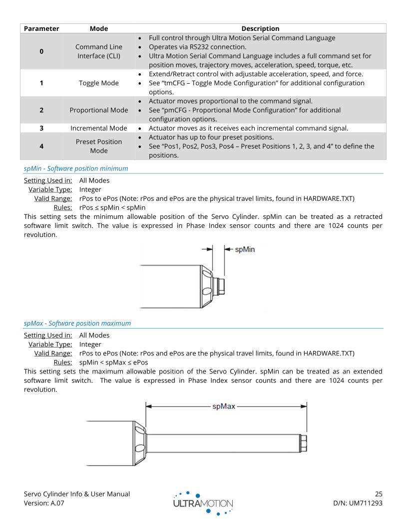
spMin - Software position minimum
Setting Used in: All Modes
Variable Type: Integer
Valid Range: rPos to ePos (Note: rPos and ePos are the physical travel limits, found in HARDWARE.TXT)
Rules: rPos ≤ spMin < spMin
This setting sets the minimum allowable position of the Servo Cylinder. spMin can be treated as a retracted
software limit switch. The value is expressed in Phase Index sensor counts and there are 1024 counts per
revolution.
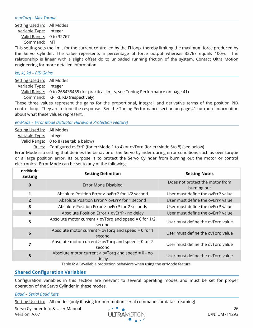
spMax - Software position maximum
Setting Used in: All Modes
Variable Type: Integer
Valid Range: rPos to ePos (Note: rPos and ePos are the physical travel limits, found in HARDWARE.TXT)
Rules: spMin < spMax ≤ ePos
This setting sets the maximum allowable position of the Servo Cylinder. spMin can be treated as an extended
software limit switch. The value is expressed in Phase Index sensor counts and there are 1024 counts per
revolution.
Servo Cylinder Info & User Manual 26
Version: A.07 D/N: UM711293
maxTorq - Max Torque
Setting Used in: All Modes
Variable Type: Integer
Valid Range: 0 to 32767
Command: MT
This setting sets the limit for the current controlled by the Fl loop, thereby limiting the maximum force produced by
the Servo Cylinder. The value represents a percentage of force output whereas 32767 equals 100%. The
relationship is linear with a slight offset do to unloaded running friction of the system. Contact Ultra Motion
engineering for more detailed information.
kp, ki, kd – PID Gains
Setting Used in: All Modes
Variable Type: Integer
Valid Range: 0 to 268435455 (for practical limits, see Tuning Performance on page 41)
Command: KP, KI, KD (respectively)
These three values represent the gains for the proportional, integral, and derivative terms of the position PID
control loop. They are to tune the response. See the Tuning Performance section on page 41 for more information
about what these values represent.
errMode – Error Mode (Actuator Hardware Protection Feature)
Setting Used in: All Modes
Variable Type: Integer
Valid Range: 0 to 8 (see table below)
Rules: Configured ovErrP (for errMode 1 to 4) or ovTorq (for errMode 5to 8) (see below)
Error Mode is a setting that defines the behavior of the Servo Cylinder during error conditions such as over torque
or a large position error. Its purpose is to protect the Servo Cylinder from burning out the motor or control
electronics. Error Mode can be set to any of the following:
errMode
Setting Setting Definition Setting Notes
0 Error Mode Disabled Does not protect the motor from
burning out
1 Absolute Position Error > ovErrP for 1/2 second User must define the ovErrP value
2 Absolute Position Error > ovErrP for 1 second User must define the ovErrP value
3 Absolute Position Error > ovErrP for 2 seconds User must define the ovErrP value
4 Absolute Position Error > ovErrP - no delay User must define the ovErrP value
5 Absolute motor current > ovTorq and speed = 0 for 1/2
second User must define the ovTorq value
6 Absolute motor current > ovTorq and speed = 0 for 1
second User must define the ovTorq value
7 Absolute motor current > ovTorq and speed = 0 for 2
second User must define the ovTorq value
8 Absolute motor current > ovTorq and speed = 0 - no
delay User must define the ovTorq value
Table 6: All available protection behaviors when using the errMode feature.
Shared Configuration Variables
Configuration variables in this section are relevant to several operating modes and must be set for proper
operation of the Servo Cylinder in these modes.
Baud – Serial Baud Rate
Setting Used in: All modes (only if using for non-motion serial commands or data streaming)
Servo Cylinder Info & User Manual 27
Version: A.07 D/N: UM711293
or Command Line Interface (CLI) (All command types)
Variable Type: Integer
Valid Range: 2400 to 256000
This setting sets the Baud rate for serial communication. Setting this is only necessary if you plan to use a serial
connection to the actuator. Serial is accessible in all control modes and is used for streaming output information
and diagnostics.
Note: Default Baud rate is 115200. Lower baud rates are more tolerant to noise and crosstalk.
maxSpeed - Maximum Speed
Setting Used in: Command Line Interface (CLI), Preset Position Mode, Toggle Mode
Variable Type: Integer
Valid Range: 0 to 50,000,000 (Practical upper limit ~8,000,000)
Command: SP
This parameter limits the maximum speed the Servo Cylinder will reach when executing trajectory moves. Note that
it is possible to set the max speed higher than what the motor is capable of outputting.
𝑆𝑚𝑎𝑥 (𝑖𝑛
𝑠) =
𝑁×1250×𝐿
216×1024, 𝐿 = 𝑠𝑐𝑟𝑒𝑤 𝑙𝑒𝑎𝑑, 𝑁 = 𝑚𝑎𝑥𝑆𝑝𝑒𝑒𝑑 𝑣𝑎𝑟𝑖𝑎𝑏𝑙𝑒
Note that this variable does not control the speed in proportional modes. Speed is controlled in proportional modes
by controlling the rate of change of the signal from your PLC or signal source.
Accel - Acceleration and Deceleration Rate
Setting Used in: Command Line Interface (CLI), Preset Position Mode, and Toggle Mode
Variable Type: Integer
Valid Range: 0 to 131071
This parameter defines the acceleration and deceleration the Servo Cylinder will use in trajectory moves. Note: the
acceleration and deceleration must be equal to one another.
𝑎(𝑖𝑛 𝑠2⁄ ) =𝑁×1,2502×𝐿
216×1024, 𝐿 = 𝑠𝑐𝑟𝑒𝑤 𝑙𝑒𝑎𝑑, 𝑁 = 𝐴𝑐𝑐𝑒𝑙 𝑣𝑎𝑟𝑖𝑎𝑏𝑙𝑒
Note that this variable does not control the acceleration of the actuator when in proportional modes. Acceleration
and deceleration are controlled in proportional modes by controlling the rate of change of the slew rate of the
analog signal.
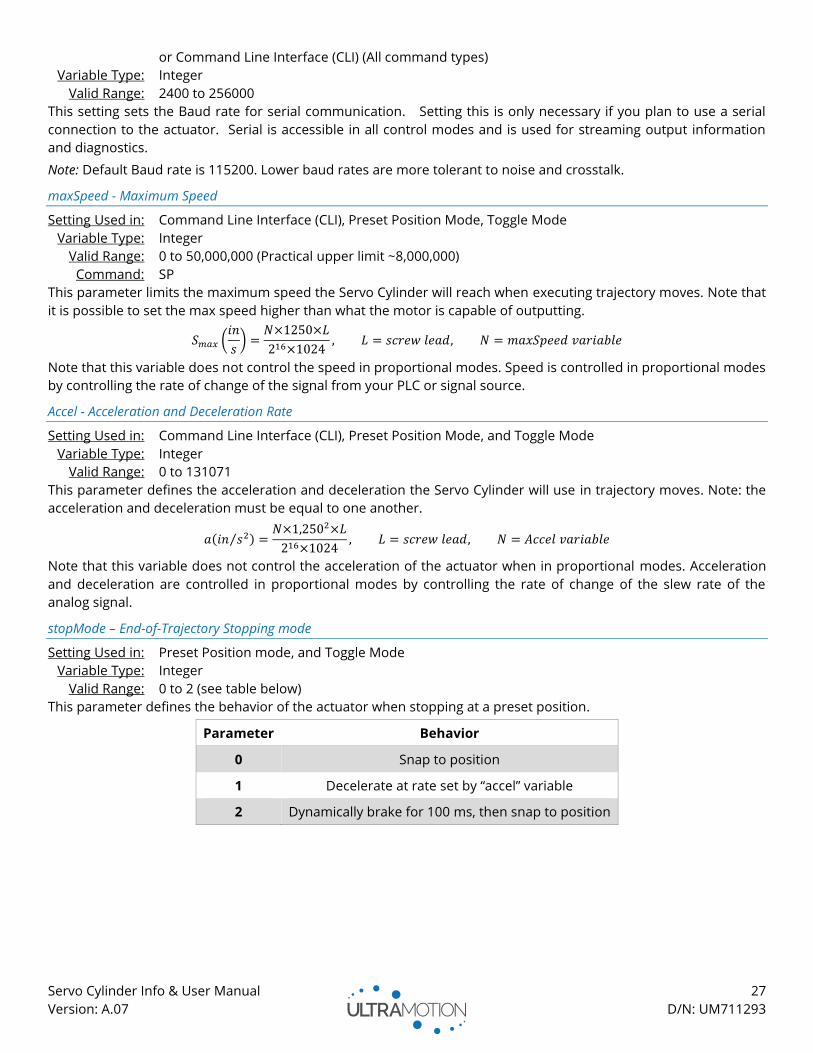
stopMode – End-of-Trajectory Stopping mode
Setting Used in: Preset Position mode, and Toggle Mode
Variable Type: Integer
Valid Range: 0 to 2 (see table below)
This parameter defines the behavior of the actuator when stopping at a preset position.
Parameter Behavior
0 Snap to position
1 Decelerate at rate set by “accel” variable
2 Dynamically brake for 100 ms, then snap to position
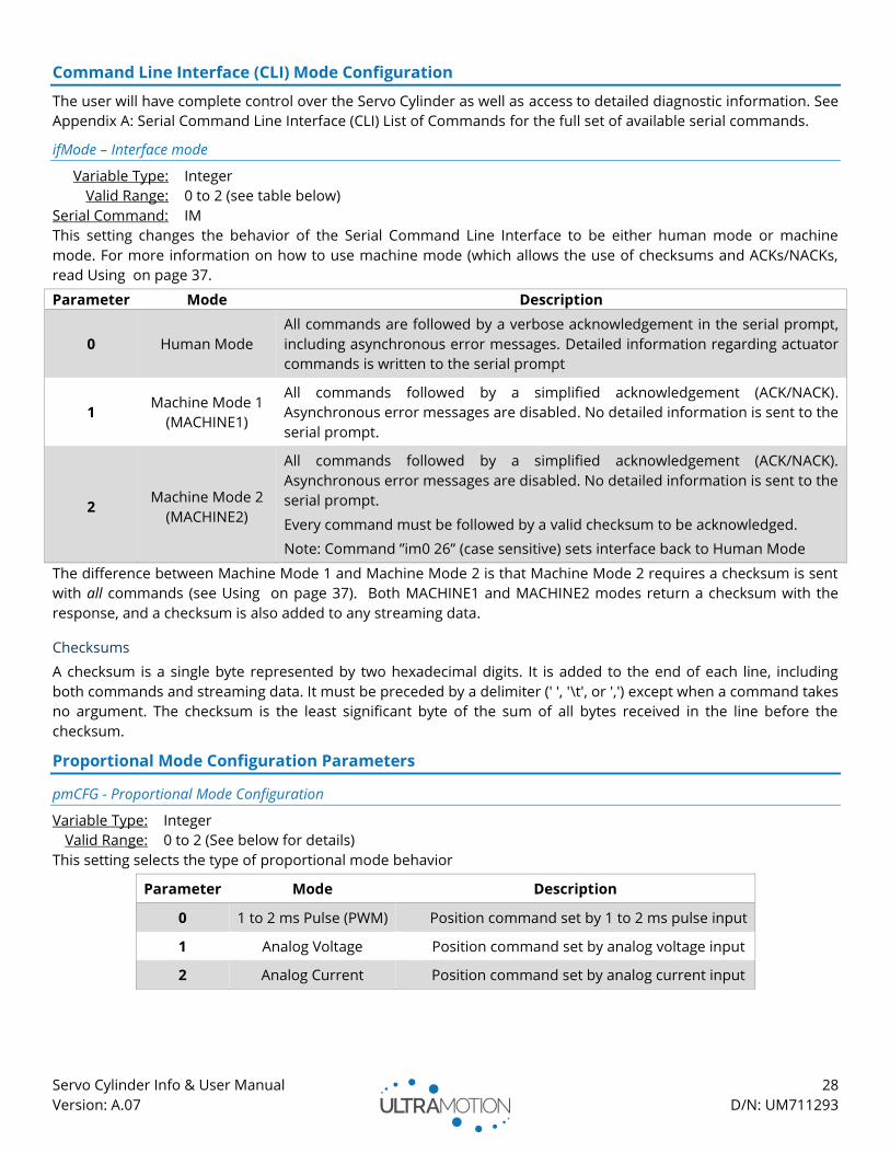
Servo Cylinder Info & User Manual 28
Version: A.07 D/N: UM711293
Command Line Interface (CLI) Mode Configuration
The user will have complete control over the Servo Cylinder as well as access to detailed diagnostic information. See
Appendix A: Serial Command Line Interface (CLI) List of Commands for the full set of available serial commands.
ifMode – Interface mode
Variable Type: Integer
Valid Range: 0 to 2 (see table below)
Serial Command: IM
This setting changes the behavior of the Serial Command Line Interface to be either human mode or machine
mode. For more information on how to use machine mode (which allows the use of checksums and ACKs/NACKs,
read Using on page 37.
Parameter Mode Description
0 Human Mode
All commands are followed by a verbose acknowledgement in the serial prompt,
including asynchronous error messages. Detailed information regarding actuator
commands is written to the serial prompt
1 Machine Mode 1
(MACHINE1)
All commands followed by a simplified acknowledgement (ACK/NACK).
Asynchronous error messages are disabled. No detailed information is sent to the
serial prompt.
2 Machine Mode 2
(MACHINE2)
All commands followed by a simplified acknowledgement (ACK/NACK).
Asynchronous error messages are disabled. No detailed information is sent to the
serial prompt.
Every command must be followed by a valid checksum to be acknowledged.
Note: Command ”im0 26” (case sensitive) sets interface back to Human Mode
The difference between Machine Mode 1 and Machine Mode 2 is that Machine Mode 2 requires a checksum is sent
with all commands (see Using on page 37). Both MACHINE1 and MACHINE2 modes return a checksum with the
response, and a checksum is also added to any streaming data.
Checksums
A checksum is a single byte represented by two hexadecimal digits. It is added to the end of each line, including
both commands and streaming data. It must be preceded by a delimiter (' ', '\t', or ',') except when a command takes
no argument. The checksum is the least significant byte of the sum of all bytes received in the line before the
checksum.
Proportional Mode Configuration Parameters
pmCFG - Proportional Mode Configuration
Variable Type: Integer
Valid Range: 0 to 2 (See below for details)
This setting selects the type of proportional mode behavior
Parameter Mode Description
0 1 to 2 ms Pulse (PWM) Position command set by 1 to 2 ms pulse input
1 Analog Voltage Position command set by analog voltage input
2 Analog Current Position command set by analog current input

Servo Cylinder Info & User Manual 29
Version: A.07 D/N: UM711293
vMin, vMax – Analog Voltage Min and Analog Voltage Max
Parameter Type: Integer
Valid Range: 0 to 65535* (Note: this integer corresponds to sensor count, not volts)
Rules: opMode=2, pmCFG = 1
vMin < vMax
This setting defines the usable range of the -10 to +10V analog voltage input that will relate to the Servo Cylinder
travel range (spMin to spMax). An example configuration is shown below.
*For optimal results the user should calibrate the minimum and maximum voltage range to each actuator.
vFilter – Analog Voltage filter
Variable Type: Integer
Valid Range: 0 to 65535
Rules: opMode=2, pmCFG = 1
The analog voltage input can be filtered in software to reduce the effect of noise from the transceiver. The larger
the value the less filtering will occur, allowing for more dynamic movements. A smaller value will increase the level
of filtering, leading to smoothed motion and less dithering.
cMin, cMax – Analog Current min and Analog Current max
Variable Type: Integer
Valid Range: 0 to 65535 (Note: this integer corresponds to sensor count, not amps)
Rules: opMode = 2, pmCFG = 2,
cMin < cMax
These parameters define the usable range of input currents relate to the Servo Cylinder travel range. Variables cMin
and cMax each set the input current (measured in ADC encoder counts) at which the actuator will have moved to
the positions spMin and spMax respectively. Input current between cMin and cMax will induce final output position
to be linearly related to its respective position between spMin and spMax
For optimal results the user should calibrate the minimum and maximum current range to each actuator, due to
small differences in each actuator and signal system. Common values for these variables are cMin = 3114 and cMax
= 64131, since these values correspond to approximately 4mA and 20mA respectively.
cFilter - Current filter
Parameter Type: Integer
Valid Range: 0 to 65535
Rules: opMode = 2, pmCFG = 2
The analog current input can be filtered in software to reduce the effect of noise from the transceiver. The larger
the value the less filtering will occur, allowing for more dynamic movements. A smaller value will increase the level
of filtering, leading to more stable motion and less dithering.
pMin, pMax – Pulse Width Minimum and Maximum
Variable Type: Integer
Valid Range: 48000 to 70000 (for pMin) and 108000 to 132000 (for pMax)
Rules: opMode = 2, pmCFG = 0
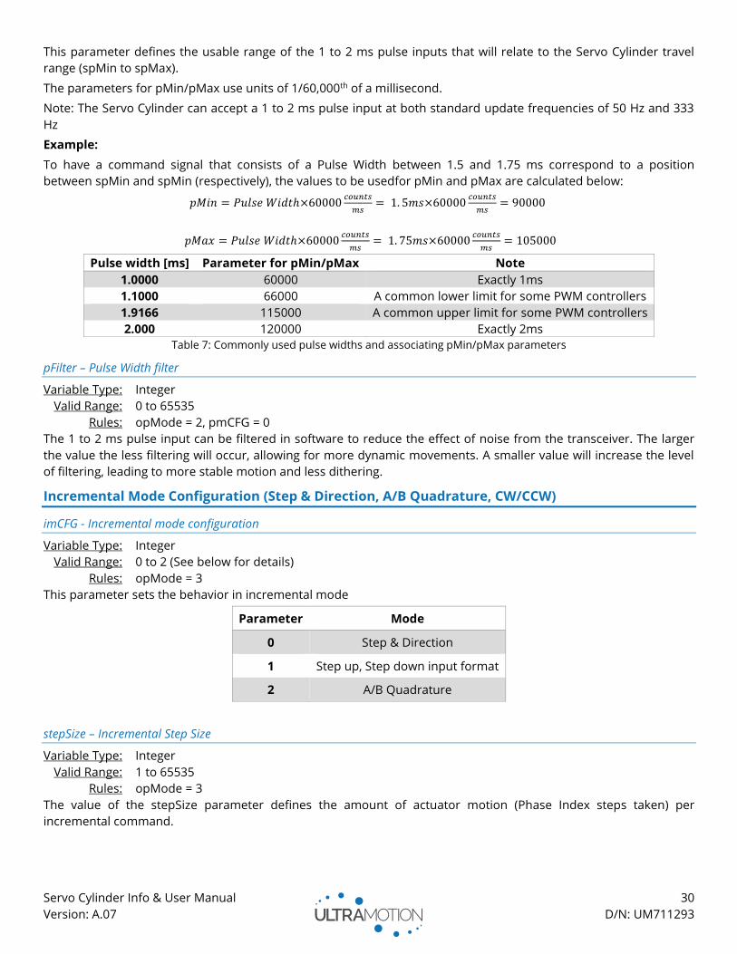
Servo Cylinder Info & User Manual 30
Version: A.07 D/N: UM711293
This parameter defines the usable range of the 1 to 2 ms pulse inputs that will relate to the Servo Cylinder travel
range (spMin to spMax).
The parameters for pMin/pMax use units of 1/60,000th of a millisecond.
Note: The Servo Cylinder can accept a 1 to 2 ms pulse input at both standard update frequencies of 50 Hz and 333
Hz
Example:
To have a command signal that consists of a Pulse Width between 1.5 and 1.75 ms correspond to a position
between spMin and spMin (respectively), the values to be usedfor pMin and pMax are calculated below:
𝑝𝑀𝑖𝑛 = 𝑃𝑢𝑙𝑠𝑒 𝑊𝑖𝑑𝑡ℎ×60000𝑐𝑜𝑢𝑛𝑡𝑠
𝑚𝑠= 1. 5𝑚𝑠×60000
𝑐𝑜𝑢𝑛𝑡𝑠
𝑚𝑠= 90000
𝑝𝑀𝑎𝑥 = 𝑃𝑢𝑙𝑠𝑒 𝑊𝑖𝑑𝑡ℎ×60000𝑐𝑜𝑢𝑛𝑡𝑠
𝑚𝑠= 1. 75𝑚𝑠×60000
𝑐𝑜𝑢𝑛𝑡𝑠
𝑚𝑠= 105000
Pulse width [ms] Parameter for pMin/pMax Note
1.0000 60000 Exactly 1ms
1.1000 66000 A common lower limit for some PWM controllers
1.9166 115000 A common upper limit for some PWM controllers
2.000 120000 Exactly 2ms
Table 7: Commonly used pulse widths and associating pMin/pMax parameters
pFilter – Pulse Width filter
Variable Type: Integer
Valid Range: 0 to 65535
Rules: opMode = 2, pmCFG = 0
The 1 to 2 ms pulse input can be filtered in software to reduce the effect of noise from the transceiver. The larger
the value the less filtering will occur, allowing for more dynamic movements. A smaller value will increase the level
of filtering, leading to more stable motion and less dithering.
Incremental Mode Configuration (Step & Direction, A/B Quadrature, CW/CCW)
imCFG - Incremental mode configuration
Variable Type: Integer
Valid Range: 0 to 2 (See below for details)
Rules: opMode = 3
This parameter sets the behavior in incremental mode
Parameter Mode
0 Step & Direction
1 Step up, Step down input format
2 A/B Quadrature
stepSize – Incremental Step Size
Variable Type: Integer
Valid Range: 1 to 65535
Rules: opMode = 3
The value of the stepSize parameter defines the amount of actuator motion (Phase Index steps taken) per
incremental command.

Servo Cylinder Info & User Manual 31
Version: A.07 D/N: UM711293
Toggle Mode Configuration
tmCFG – Toggle Mode Configuration
Variable Type: Integer
Valid Range: 0 to 4
Rules: opMode = 1
This parameter sets behavior in toggle mode
Parameter Description Notes
0 Speed and Torque set in CONFIG.TXT Torque and speed are static settings
1 Voltage sets speed, torque set in CONFIG.TXT Dynamically controllable torque
2 Current sets speed, torque set in CONFIG.TXT Dynamically controllable torque
3 Speed set in CONFIG.TXT, voltage sets torque Dynamically controllable speed
4 Speed set in CONFIG.TXT, current sets torque Dynamically controllable speed
mtMin - Max Torque Minimum
Variable Type: Integer
Valid Range: 0 to 32766
Rules: tmCFG = 1 or 2
Since you are using an adjustable range to set the torque limit, this variable defines the lower limit for the maxTorq
variable.
For Example: You want to use a 0 to 10V input to control torque in a range from mtMin to maxTorq
msMin – Max Speed Minimum
Variable Type: Integer
Valid Range: 0 to 32766
Rules: tmCFG = 1 or 2
Since you are using a range to define the speed, this defines the lower limit for the range. The upper limit is defined
by maxSpeed.
For Example: You want to use a 0 to 10V input to control speed in a range from msMin to maxSpeed
Preset Position Mode Configuration
Preset position mode is a simple way to move between up to four absolute positions with simple digital commands.
The state of the Servo Cylinder’s two optically isolated digital inputs (IN1 and IN2) corresponds to the absolute
position command. Four preset position mode uses the maximum speed and acceleration values (maxSpeed, accel)
to create trajectories when moving from one preset position to another. A user configurable time delay (posTime) is
used to reject noise or invalid states sent to the actuator.
posTime – Preset Position Response Time
Variable Type: Integer
Valid Range: 0 to 65535
Rules: opMode = 4
This parameter defines the amount of time in milliseconds it takes for a state change on the optically isolated digital
inputs (IN1 and IN2) to register as a valid command.
Pos1, Pos2, Pos3, Pos4 – Preset Positions 1, 2, 3, and 4
Variable Type: Integer
Valid Range: spMin to spMax
Rules: opMode = 4
These parameters define the absolute position that corresponds to each state of the digital inputs.
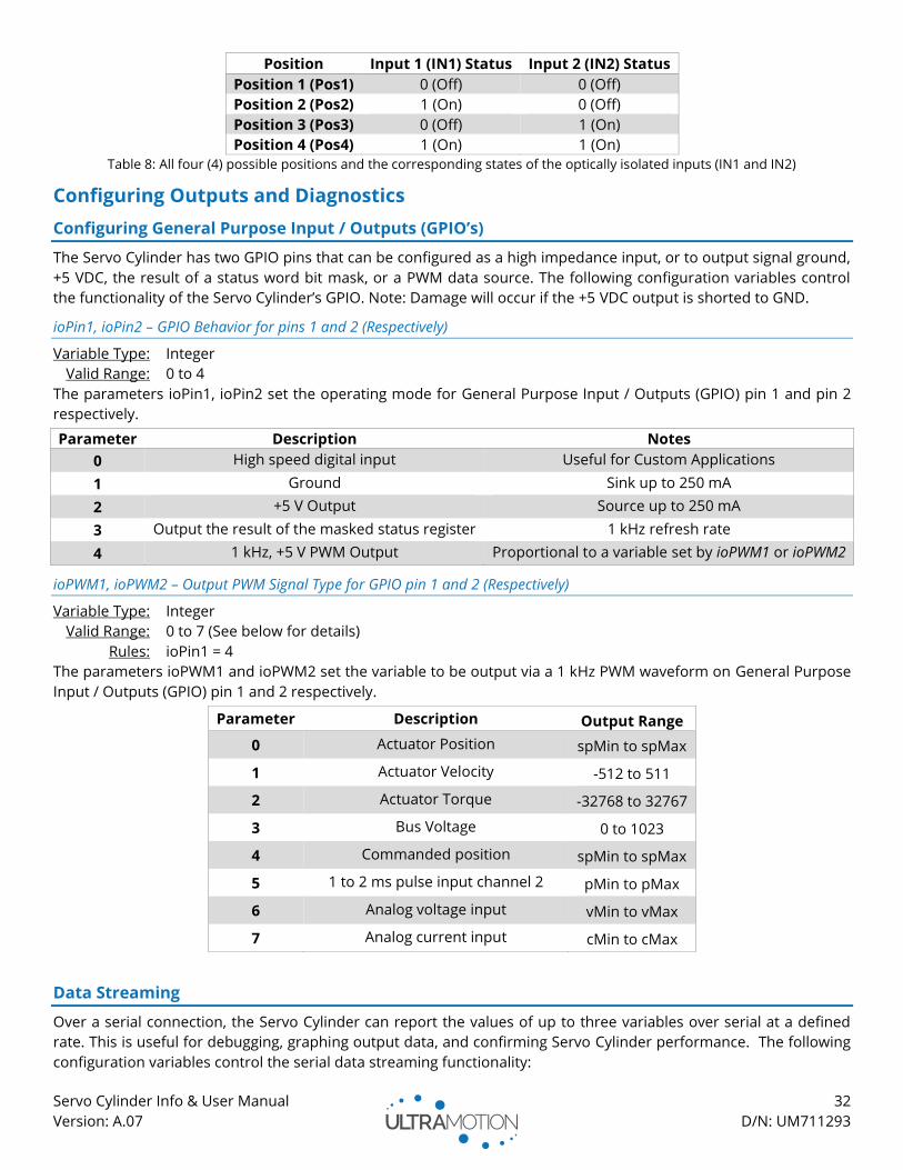
Servo Cylinder Info & User Manual 32
Version: A.07 D/N: UM711293
Position Input 1 (IN1) Status Input 2 (IN2) Status
Position 1 (Pos1) 0 (Off) 0 (Off)
Position 2 (Pos2) 1 (On) 0 (Off)
Position 3 (Pos3) 0 (Off) 1 (On)
Position 4 (Pos4) 1 (On) 1 (On)
Table 8: All four (4) possible positions and the corresponding states of the optically isolated inputs (IN1 and IN2)
Configuring Outputs and Diagnostics
Configuring General Purpose Input / Outputs (GPIO’s)
The Servo Cylinder has two GPIO pins that can be configured as a high impedance input, or to output signal ground,
+5 VDC, the result of a status word bit mask, or a PWM data source. The following configuration variables control
the functionality of the Servo Cylinder’s GPIO. Note: Damage will occur if the +5 VDC output is shorted to GND.
ioPin1, ioPin2 – GPIO Behavior for pins 1 and 2 (Respectively)
Variable Type: Integer
Valid Range: 0 to 4
The parameters ioPin1, ioPin2 set the operating mode for General Purpose Input / Outputs (GPIO) pin 1 and pin 2
respectively.
Parameter Description Notes
0 High speed digital input Useful for Custom Applications
1 Ground Sink up to 250 mA
2 +5 V Output Source up to 250 mA
3 Output the result of the masked status register 1 kHz refresh rate
4 1 kHz, +5 V PWM Output Proportional to a variable set by ioPWM1 or ioPWM2
ioPWM1, ioPWM2 – Output PWM Signal Type for GPIO pin 1 and 2 (Respectively)
Variable Type: Integer
Valid Range: 0 to 7 (See below for details)
Rules: ioPin1 = 4
The parameters ioPWM1 and ioPWM2 set the variable to be output via a 1 kHz PWM waveform on General Purpose
Input / Outputs (GPIO) pin 1 and 2 respectively.
Parameter Description Output Range
0 Actuator Position spMin to spMax
1 Actuator Velocity -512 to 511
2 Actuator Torque -32768 to 32767
3 Bus Voltage 0 to 1023
4 Commanded position spMin to spMax
5 1 to 2 ms pulse input channel 2 pMin to pMax
6 Analog voltage input vMin to vMax
7 Analog current input cMin to cMax
Data Streaming
Over a serial connection, the Servo Cylinder can report the values of up to three variables over serial at a defined
rate. This is useful for debugging, graphing output data, and confirming Servo Cylinder performance. The following
configuration variables control the serial data streaming functionality:

Servo Cylinder Info & User Manual 33
Version: A.07 D/N: UM711293
sFlag
Variable Type: Integer
Valid Range: 0 or 1 (See below for details)
This parameter defines the start-up behavior of the data streaming functionality.
Parameter Description
0 Data streaming off at startup
1 Data streaming on at power-up
sTime
Variable Type: Integer
Valid Range: 0 to 65535 (See below for details)
This parameter defines the rate at which data is streamed from the actuator. This will be limited by the pre-selected
baud rate. 65535 is the minimum data transfer rate (~3.576 Hz), the maximum data transfer rate is a function of the
baud rate.
Baud Rate Maximum Streaming Frequency
9600 24.0 Hz
19200 48.0 Hz
38400 96.0 Hz
57600 144.0 Hz
115200 287.9 Hz

Servo Cylinder Info & User Manual 34
Version: A.07 D/N: UM711293
Strx1, Strx2, Strx3 – Streamed Variables
Variable Type: Integer
Valid Range: 0 to 19 (See below for details)
This parameter defines the variable that will be streamed in columns 1, 2, and 3 respectively.
Parameter Description
0 Column Off
1 Actuator Position
2 Position Command Setpoint
3 Motor Current
4 Motor Current Setpoint
5 Motor Phase 1 Current
6 Motor Phase 2 Current
7 Motor Phase 3 Current
8 Actuator Velocity at 312.5 kHz
9 Actuator Velocity at 78.125 Hz
10 Encoder Interval Timer
11 Supply Voltage
12 Status Bit Register
13 1 to 2 ms pulse (PWM) Input
14 Filtered 1 to 2 ms pulse (PWM) Input
15 Analog Voltage Input
16 Filtered Analog Voltage Input
17 Analog Current Input
18 Filtered Analog Current Input
19 Temperature Sensor Input
20 Position Error
21 Quadrature Input Errors
22 1 to 2 ms pulse (PWM) input errors
23 32-bit Timer with 100 µs Increments
Table 9: All available streamed variables
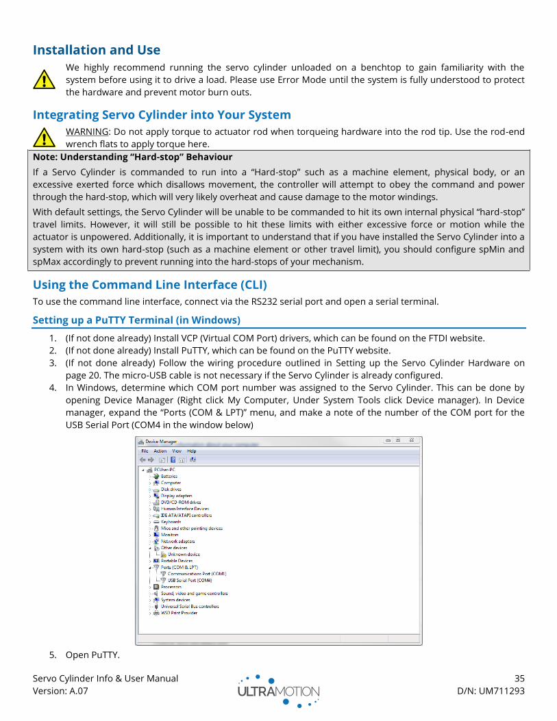
Servo Cylinder Info & User Manual 35
Version: A.07 D/N: UM711293
Installation and Use
We highly recommend running the servo cylinder unloaded on a benchtop to gain familiarity with the
system before using it to drive a load. Please use Error Mode until the system is fully understood to protect
the hardware and prevent motor burn outs.
Integrating Servo Cylinder into Your System
WARNING: Do not apply torque to actuator rod when torqueing hardware into the rod tip. Use the rod-end
wrench flats to apply torque here.
Note: Understanding “Hard-stop” Behaviour
If a Servo Cylinder is commanded to run into a “Hard-stop” such as a machine element, physical body, or an
excessive exerted force which disallows movement, the controller will attempt to obey the command and power
through the hard-stop, which will very likely overheat and cause damage to the motor windings.
With default settings, the Servo Cylinder will be unable to be commanded to hit its own internal physical “hard-stop”
travel limits. However, it will still be possible to hit these limits with either excessive force or motion while the
actuator is unpowered. Additionally, it is important to understand that if you have installed the Servo Cylinder into a
system with its own hard-stop (such as a machine element or other travel limit), you should configure spMin and
spMax accordingly to prevent running into the hard-stops of your mechanism.
Using the Command Line Interface (CLI)
To use the command line interface, connect via the RS232 serial port and open a serial terminal.
Setting up a PuTTY Terminal (in Windows)
1. (If not done already) Install VCP (Virtual COM Port) drivers, which can be found on the FTDI website.
2. (If not done already) Install PuTTY, which can be found on the PuTTY website.
3. (If not done already) Follow the wiring procedure outlined in Setting up the Servo Cylinder Hardware on
page 20. The micro-USB cable is not necessary if the Servo Cylinder is already configured.
4. In Windows, determine which COM port number was assigned to the Servo Cylinder. This can be done by
opening Device Manager (Right click My Computer, Under System Tools click Device manager). In Device
manager, expand the “Ports (COM & LPT)” menu, and make a note of the number of the COM port for the
USB Serial Port (COM4 in the window below)
5. Open PuTTY.
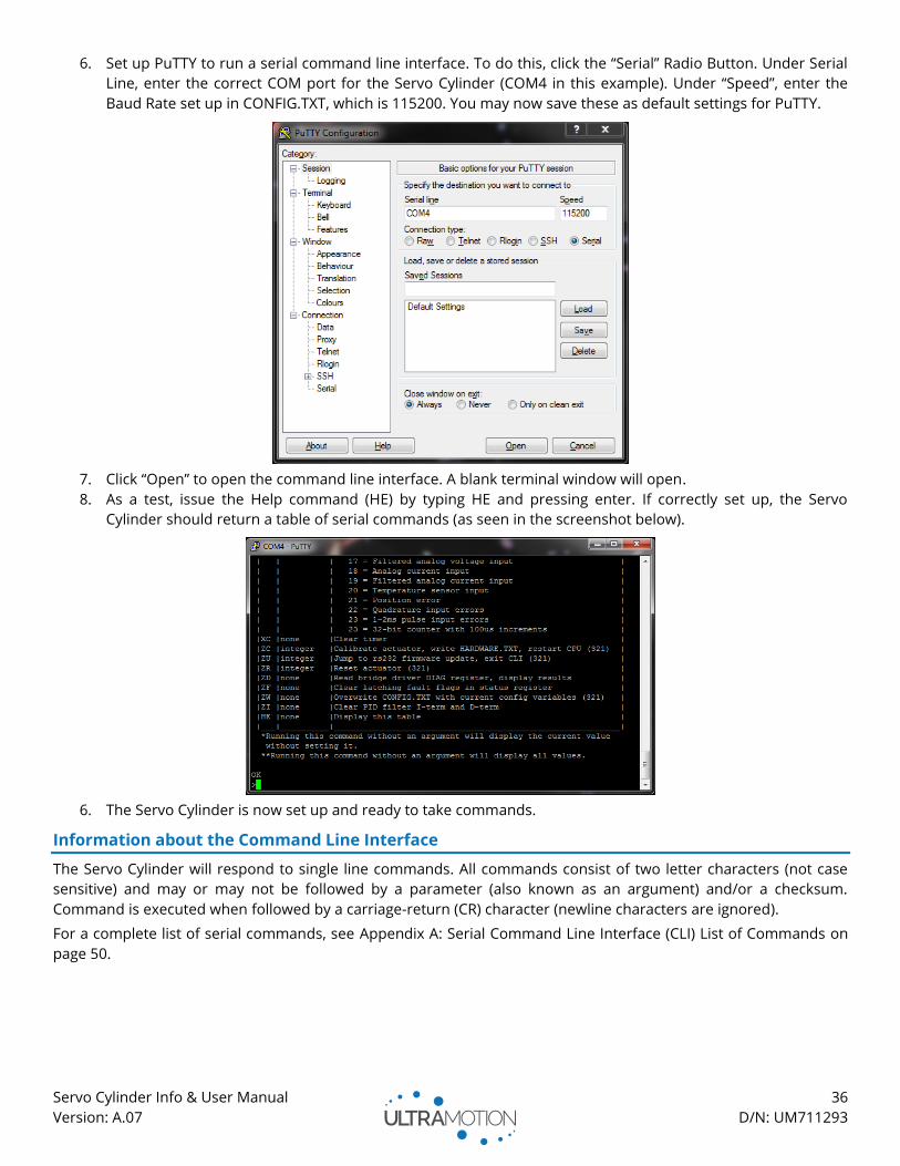
Servo Cylinder Info & User Manual 36
Version: A.07 D/N: UM711293
6. Set up PuTTY to run a serial command line interface. To do this, click the “Serial” Radio Button. Under Serial
Line, enter the correct COM port for the Servo Cylinder (COM4 in this example). Under “Speed”, enter the
Baud Rate set up in CONFIG.TXT, which is 115200. You may now save these as default settings for PuTTY.
7. Click “Open” to open the command line interface. A blank terminal window will open.
8. As a test, issue the Help command (HE) by typing HE and pressing enter. If correctly set up, the Servo
Cylinder should return a table of serial commands (as seen in the screenshot below).
6. The Servo Cylinder is now set up and ready to take commands.
Information about the Command Line Interface
The Servo Cylinder will respond to single line commands. All commands consist of two letter characters (not case
sensitive) and may or may not be followed by a parameter (also known as an argument) and/or a checksum.
Command is executed when followed by a carriage-return (CR) character (newline characters are ignored).
For a complete list of serial commands, see Appendix A: Serial Command Line Interface (CLI) List of Commands on
page 50.
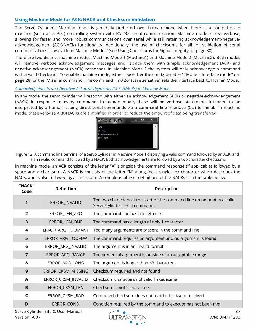
Servo Cylinder Info & User Manual 37
Version: A.07 D/N: UM711293
Using Machine Mode for ACK/NACK and Checksum Validation
The Servo Cylinder’s Machine mode is generally preferred over human mode when there is a computerized
machine (such as a PLC) controlling system with RS-232 serial communication. Machine mode is less verbose,
allowing for faster and more robust communications over serial while still retaining acknowledgement/negative-
acknowledgement (ACK/NACK) functionality. Additionally, the use of checksums for all for validation of serial
communications is available in Machine Mode 2 (see Using Checksums for Signal Integrity on page 38)
There are two distinct machine modes, Machine Mode 1 (Machine1) and Machine Mode 2 (Machine2). Both modes
will remove verbose acknowledgement messages and replace them with simple acknowledgement (ACK) and
negative-acknowledgement (NACK) responses. In Machine Mode 2 the system will only acknowledge a command
with a valid checksum. To enable machine mode, either use either the config variable “ifMode – Interface mode” (on
page 28) or the IM serial command. The command ”im0 26” (case sensitive) sets the interface back to Human Mode.
Acknowledgements and Negative-Acknowledgements (ACKs/NACKs) in Machine Mode
In any mode, the servo cylinder will respond with either an acknowledgement (ACK) or negative-acknowledgement
(NACK) in response to every command. In human mode, these will be verbose statements intended to be
interpreted by a human issuing direct serial commands via a command line interface (CLI) terminal. In machine
mode, these verbose ACK/NACKs are simplified in order to reduce the amount of data being transferred.
Figure 12: A command line terminal of a Servo Cylinder in Machine Mode 1 displaying a valid command followed by an ACK, and
a an invalid command followed by a NACK. Both acknowledgements are followed by a two character checksum.
In machine mode, an ACK consists of the letter “A” alongside the command response (if applicable) followed by a
space and a checksum. A NACK is consists of the letter “N” alongside a single hex character which describes the
NACK, and is also followed by a checksum. A complete table of definitions of the NACKs is in the table below.
“NACK”
Code Definition Description
1 ERROR_INVALID The two characters at the start of the command line do not match a valid
Servo Cylinder serial command.
2 ERROR_LEN_ZRO The command line has a length of 0
3 ERROR_LEN_ONE The command has a length of only 1 character
4 ERROR_ARG_TOOMANY Too many arguments are present in the command line
5 ERROR_ARG_TOOFEW The command requires an argument and no argument is found
6 ERROR_ARG_INVALID The argument is in an invalid format
7 ERROR_ARG_RANGE The numerical argument is outside of an acceptable range
8 ERROR_ARG_LONG The argument is longer than 63 characters
9 ERROR_CKSM_MISSING Checksum required and not found
A ERROR_CKSM_INVALID Checksum characters not valid hexadecimal
B ERROR_CKSM_LEN Checksum is not 2 characters
C ERROR_CKSM_BAD Computed checksum does not match checksum received
D ERROR_COND Condition required by the command to execute has not been met
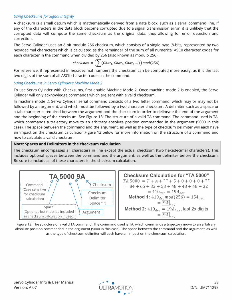
Servo Cylinder Info & User Manual 38
Version: A.07 D/N: UM711293
Using Checksums for Signal Integrity
A checksum is a small datum which is mathematically derived from a data block, such as a serial command line. If
any of the characters in the data block become corrupted due to a signal transmission error, it is unlikely that the
corrupted data will compute the same checksum as the original data, thus allowing for error detection and
correction.
The Servo Cylinder uses an 8 bit modulo 256 checksum, which consists of a single byte (8-bits, represented by two
hexadecimal characters) which is calculated as the remainder of the sum of all numerical ASCII character codes for
each character in the command when divided by 256 (also known as modulo 256).
𝑐ℎ𝑒𝑐𝑘𝑠𝑢𝑚 = (∑(𝐶ℎ𝑎𝑟1, 𝐶ℎ𝑎𝑟2, 𝐶ℎ𝑎𝑟3 … )) 𝑚𝑜𝑑(256)
For reference, if represented in hexadecimal numbers the checksum can be computed more easily, as it is the last
two digits of the sum of all ASCII character codes in the command.
Using Checksums in Servo Cylinder’s Machine Mode 2
To use Servo Cylinder with Checksums, first enable Machine Mode 2. Once machine mode 2 is enabled, the Servo
Cylinder will only acknowledge commands which are sent with a valid checksum.
In machine mode 2, Servo Cylinder serial command consists of a two letter command, which may or may not be
followed by an argument, and which must be followed by a two character checksum. A delimiter such as a space or
a tab character is required between the argument and the checksum in order to delineate the end of the argument
and the beginning of the checksum. See Figure 13: The structure of a valid TA command. The command used is TA,
which commands a trajectory move to an arbitrary absolute position commanded in the argument (5000 in this
case). The space between the command and the argument, as well as the type of checksum delimiter will each have
an impact on the checksum calculation.Figure 13 below for more information on the structure of a command and
how to calculate a valid checksum.
Note: Spaces and Delimiters in the checksum calculation
The checksum encompasses all characters in line except the actual checksum (two hexadecimal characters). This
includes optional spaces between the command and the argument, as well as the delimiter before the checksum.
Be sure to include all of these characters in the checksum calculation.
Figure 13: The structure of a valid TA command. The command used is TA, which commands a trajectory move to an arbitrary
absolute position commanded in the argument (5000 in this case). The space between the command and the argument, as well
as the type of checksum delimiter will each have an impact on the checksum calculation.
TA 5000 9A
Command
(Case sensitive
for checksum
calculation)
Space
(Optional, but must be included
in checksum calculation if used) Argument
Checksum
Delimiter
(Space " ")
Checksum
Checksum Calculation for “TA 5000” 𝑇𝐴 5000 = 𝑇 + 𝐴 + " " + 5 + 0 + 0 + 0 + " "
= 84 + 65 + 32 + 53 + 48 + 48 + 48 + 32
= 410𝑑𝑒𝑐 = 19𝐴ℎ𝑒𝑥
Method 1: 410𝑑𝑒𝑐𝑚𝑜𝑑(256) = 154𝑑𝑒𝑐
= 9𝐴ℎ𝑒𝑥
Method 2: 410𝑑𝑒𝑐 = 19𝐴ℎ𝑒𝑥, last 2x digits
= 9𝐴ℎ𝑒𝑥
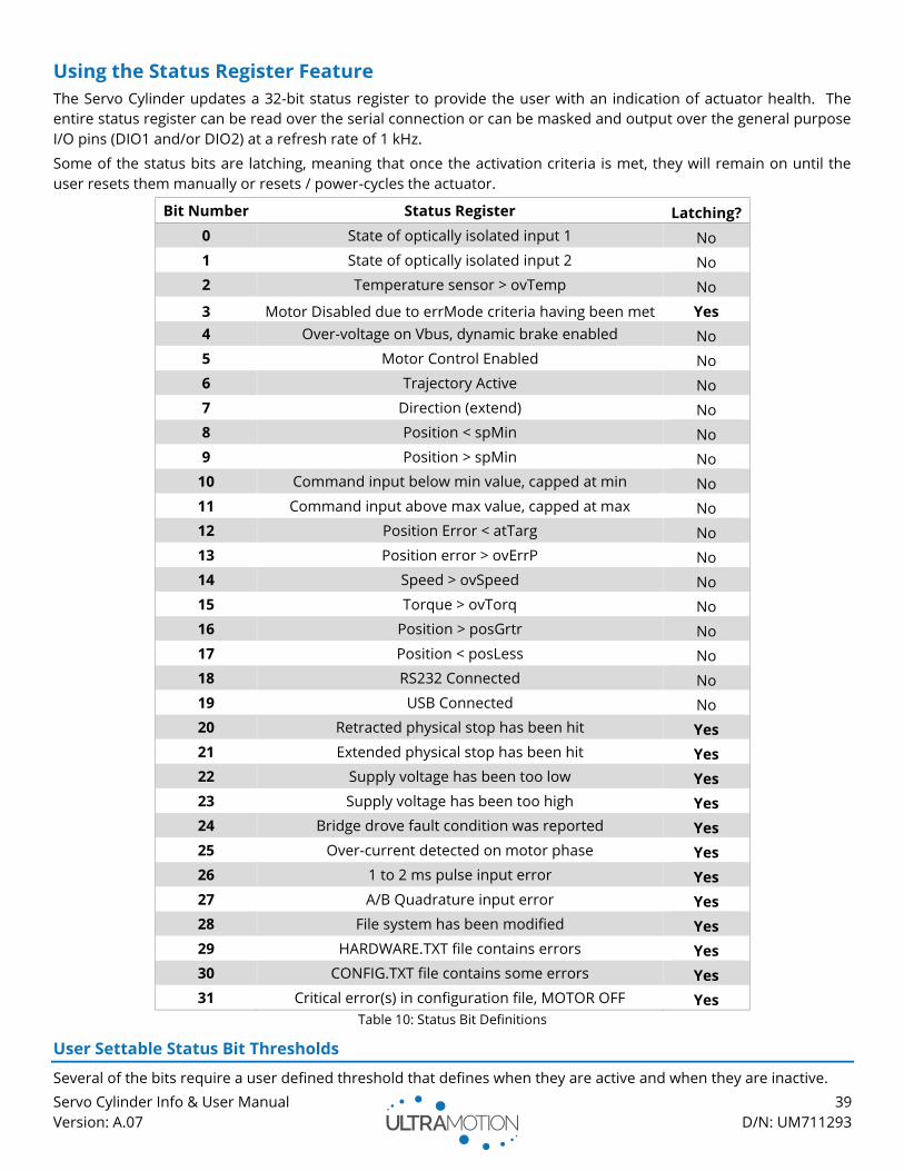
Servo Cylinder Info & User Manual 39
Version: A.07 D/N: UM711293
Using the Status Register Feature
The Servo Cylinder updates a 32-bit status register to provide the user with an indication of actuator health. The
entire status register can be read over the serial connection or can be masked and output over the general purpose
I/O pins (DIO1 and/or DIO2) at a refresh rate of 1 kHz.
Some of the status bits are latching, meaning that once the activation criteria is met, they will remain on until the
user resets them manually or resets / power-cycles the actuator.
Bit Number Status Register Latching?
0 State of optically isolated input 1 No
1 State of optically isolated input 2 No
2 Temperature sensor > ovTemp No
3 Motor Disabled due to errMode criteria having been met Yes
4 Over-voltage on Vbus, dynamic brake enabled No
5 Motor Control Enabled No
6 Trajectory Active No
7 Direction (extend) No
8 Position < spMin No
9 Position > spMin No
10 Command input below min value, capped at min No
11 Command input above max value, capped at max No
12 Position Error < atTarg No
13 Position error > ovErrP No
14 Speed > ovSpeed No
15 Torque > ovTorq No
16 Position > posGrtr No
17 Position < posLess No
18 RS232 Connected No
19 USB Connected No
20 Retracted physical stop has been hit Yes
21 Extended physical stop has been hit Yes
22 Supply voltage has been too low Yes
23 Supply voltage has been too high Yes
24 Bridge drove fault condition was reported Yes
25 Over-current detected on motor phase Yes
26 1 to 2 ms pulse input error Yes
27 A/B Quadrature input error Yes
28 File system has been modified Yes
29 HARDWARE.TXT file contains errors Yes
30 CONFIG.TXT file contains some errors Yes
31 Critical error(s) in configuration file, MOTOR OFF Yes
Table 10: Status Bit Definitions
User Settable Status Bit Thresholds
Several of the bits require a user defined threshold that defines when they are active and when they are inactive.
Servo Cylinder Info & User Manual 40
Version: A.07 D/N: UM711293
atTarg – At Target Position Threshold
Parameter Type: Integer
Valid Range: 0 to 4095
Defines the position error threshold that cause bit 12 (Position Error < atTarg) to go active. The “at target position”
bit will flip when the actuator position falls between setpoint ± atTarg.
ovErrP – Position Error Threshold
Parameter Type: Integer
Valid Range: 0 to 65535
Defines the position error threshold that causes status bit 13 (Position error > ovErrP) to trigger.
ovSpeed – Over Speed Threshold
Parameter Type: Integer
Valid Range: 0 to 127
Defines the speed error threshold that causes status bit 14 (Speed > ovSpeed) to go active.
ovTorq – Over Torque Threshold
Parameter Type: Integer
Valid Range: 0 to 32767
Defines the torque threshold that causes status bit 15 (Torque > ovTorq) to go active.
posGrtr – Position Greater Than Threshold
Parameter Type: Integer
Valid Range: 0 to 65535
Defines the threshold that causes status bit 16 (Position > posGrtr) to go active. For example, setting posGrtr =
35000 will cause an active bit if the actuator position is 35001 and an inactive bit if the actuator position is 34999.
posLess – Position Less Than Threshold
Parameter Type: Integer
Valid Range: 0 to 65535
Defines the threshold that causes status bit 17 (Position < posLess) to go active. For example, setting posLess =
5000 will cause an active bit if the actuator position is 4999 and an inactive bit if the actuator position is 5001.
Reading the Status Register over Serial
The complete status register (or individual status bits) can be read over a serial connection using the “SR” command.
Sending the SR command without an argument will return the value of the status register in hex format. Calling the
SR command followed by a value from 0 to 31 will return the value of the corresponding status register bit.
For example:
Input: SR 4
Output: bit4: "Emergency over-volt" = false
Input: SR
Output: Status Register: 0x000610A7
Reading the Status Register over the General Purpose I/O Pins (DIO1 and DIO2)
Unlike the serial connection, the DIO pins can only output a single bit at a 1 kHz update rate. In order to provide
more useful information over this single bit, the status register must be masked. For this to be possible, you must
first configure the GPIO pins (1 and/or 2) to output the masked status register. See the GPIO section for information
on configuring the GPIO pins.
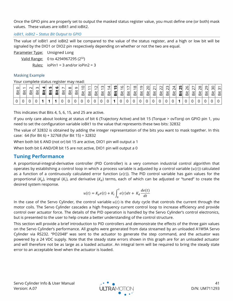
Servo Cylinder Info & User Manual 41
Version: A.07 D/N: UM711293
Once the GPIO pins are properly set to output the masked status register value, you must define one (or both) mask
values. These values are ioBit1 and ioBit2.
ioBit1, ioBit2 – Status Bit Output to GPIO
The value of ioBit1 and ioBit2 will be compared to the value of the status register, and a high or low bit will be
signaled by the DIO1 or DIO2 pin respectively depending on whether or not the two are equal.
Parameter Type: Unsigned Long
Valid Range: 0 to 4294967295 (232)
Rules: ioPin1 = 3 and/or ioPin2 = 3
Masking Example
Your complete status register may read:
Bit
0
Bit
1
Bit
2
Bit
3
Bit
4
Bit
5
Bit
6
Bit
7
Bit
8
Bit
9
Bit
10
Bit
11
Bit
12
Bit
13
Bit
14
Bit
15
Bit
16
Bit
17
Bit
18
Bit
19
Bit
20
Bit
21
Bit
22
Bit
23
Bit
24
Bit
25
Bit
26
Bit
27
Bit
28
Bit
29
Bit
30
Bit
31
0 0 0 0 1 1 1 0 0 0 0 0 0 0 0 1 0 0 0 0 0 0 0 0 0 1 0 0 0 0 0 0
This indicates that Bits 4, 5, 6, 15, and 25 are active.
If you only care about looking at status of bit 6 (Trajectory Active) and bit 15 (Torque > ovTorq) on GPIO pin 1, you
need to set the configuration variable ioBit1 to the value that represents these two bits: 32832
The value of 32832 is obtained by adding the integer representation of the bits you want to mask together. In this
case: 64 (for Bit 6) + 32768 (for Bit 15) = 32832
When both bit 6 AND (not or) bit 15 are active, DIO1 pin will output a 1
When both bit 6 AND/OR bit 15 are not active, DIO1 pin will output a 0
Tuning Performance
A proportional-integral-derivative controller (PID Controller) is a very common industrial control algorithm that
operates by establishing a control loop in which a process variable is adjusted by a control variable (𝑢(𝑡)) calculated
as a function of a continuously calculated error function (𝑒(𝑡)). The PID control variable has gain values for the
proportional (𝐾𝑝), integral (𝐾𝑖), and derivative (𝐾𝑑) terms, each of which can be adjusted or “tuned” to create the
desired system response.
𝑢(𝑡) = 𝐾𝑝𝑒(𝑡) + 𝐾𝑖 ∫ 𝑒(𝜏)𝑑𝜏𝑡
0
+ 𝐾𝑑
𝑑𝑒(𝑡)
𝑑𝑡
In the case of the Servo Cylinder, the control variable 𝑢(𝑡) is the duty cycle that controls the current through the
motor coils. The Servo Cylinder cascades a high frequency current control loop to increase efficiency and provide
control over actuator force. The details of the PID operation is handled by the Servo Cylinder’s control electronics,
but is presented to the user to help create a better understanding of the control structure.
This section will provide a brief introduction to PID controllers and demonstrate the effects of the three gain values
on the Servo Cylinder’s performance. All graphs were generated from data streamed by an unloaded A1W9A Servo
Cylinder via RS232. “PO2048” was sent to the actuator to generate the step command, and the actuator was
powered by a 24 VDC supply. Note that the steady state errors shown in this graph are for an unloaded actuator
and will therefore not be as large as a loaded actuator. An integral term will be required to bring the steady state
error to an acceptable level when the actuator is loaded.
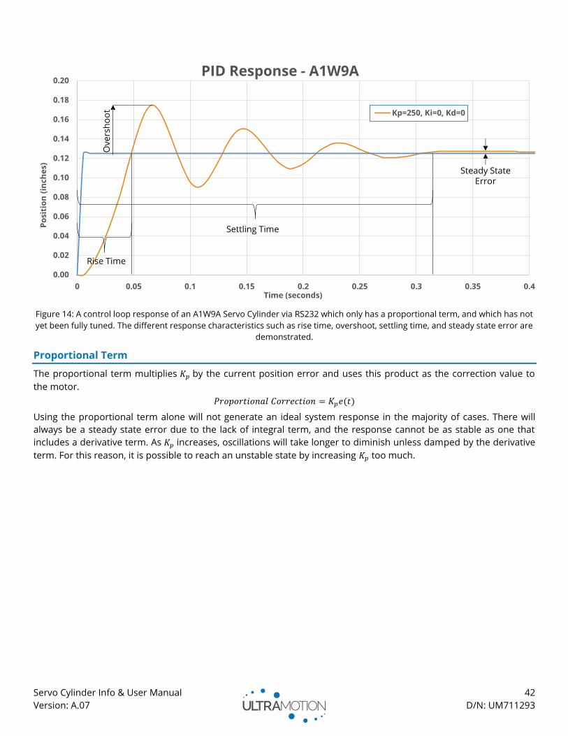
Servo Cylinder Info & User Manual 42
Version: A.07 D/N: UM711293
Figure 14: A control loop response of an A1W9A Servo Cylinder via RS232 which only has a proportional term, and which has not
yet been fully tuned. The different response characteristics such as rise time, overshoot, settling time, and steady state error are
demonstrated.
Proportional Term
The proportional term multiplies 𝐾𝑝 by the current position error and uses this product as the correction value to
the motor.
𝑃𝑟𝑜𝑝𝑜𝑟𝑡𝑖𝑜𝑛𝑎𝑙 𝐶𝑜𝑟𝑟𝑒𝑐𝑡𝑖𝑜𝑛 = 𝐾𝑝𝑒(𝑡)
Using the proportional term alone will not generate an ideal system response in the majority of cases. There will
always be a steady state error due to the lack of integral term, and the response cannot be as stable as one that
includes a derivative term. As 𝐾𝑝 increases, oscillations will take longer to diminish unless damped by the derivative
term. For this reason, it is possible to reach an unstable state by increasing 𝐾𝑝 too much.

Servo Cylinder Info & User Manual 43
Version: A.07 D/N: UM711293
Figure 15: Control loop response with various 𝐾𝑝 values. Note that the rise time, overshoot, and steady state error are inversely
proportional to 𝐾𝑝. The oscillation frequency and the settling time have increased proportionally with 𝐾𝑝.
Integral Term
The integral term is a time-based correction that uses the sum of the past errors to create a motor command.
Unlike the proportional term, the integral term will accumulate to large values over time even when the
instantaneous error is very small. The Integral term is necessary to reduce steady state error.
𝐼𝑛𝑡𝑒𝑔𝑟𝑎𝑙 𝐶𝑜𝑟𝑟𝑒𝑐𝑡𝑖𝑜𝑛 = 𝐾𝑖 ∫ 𝑒(𝜏)𝑑𝜏𝑡
0
The integral term should always be used in conjunction with a proportional and derivative term. The use of just the
integral term (𝐾𝑝 = 0, 𝐾𝑑 = 0) will lead to instability and potential damage to the actuator and associated
mechanism.
Derivative Term
The derivative term acts by reducing the rate of change of the error. As shown in the chart below, the addition of
the derivative term provides a damping action to the system response, which has the effect of reducing oscillations
and overshoot, and increasing the rise time.
𝐷𝑒𝑟𝑖𝑣𝑎𝑡𝑖𝑣𝑒 𝐶𝑜𝑟𝑟𝑒𝑐𝑡𝑖𝑜𝑛 = 𝐾𝑑
𝑑𝑒(𝑡)
𝑑𝑡
0.00
0.02
0.04
0.06
0.08
0.10
0.12
0.14
0.16
0.18
0.20
0 0.05 0.1 0.15 0.2 0.25 0.3 0.35 0.4 0.45
Po
siti
on
(in
ch
es)
Time (seconds)
PID Response - A1W9A
Kp=50, Ki=0, Kd=0
Kp=750, Ki=0, Kd=0
Kp=1500, Ki=0, Kd=0
Setpoint
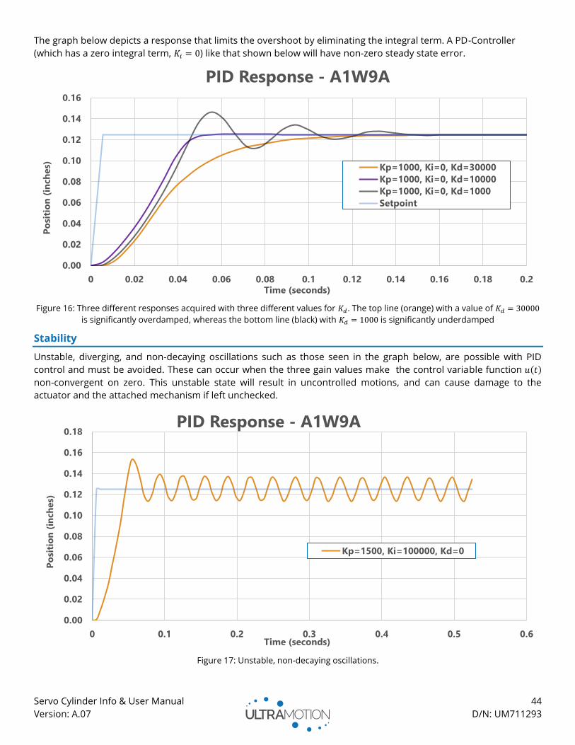
Servo Cylinder Info & User Manual 44
Version: A.07 D/N: UM711293
The graph below depicts a response that limits the overshoot by eliminating the integral term. A PD-Controller
(which has a zero integral term, 𝐾𝑖 = 0) like that shown below will have non-zero steady state error.
Figure 16: Three different responses acquired with three different values for 𝐾𝑑. The top line (orange) with a value of 𝐾𝑑 = 30000
is significantly overdamped, whereas the bottom line (black) with 𝐾𝑑 = 1000 is significantly underdamped
Stability
Unstable, diverging, and non-decaying oscillations such as those seen in the graph below, are possible with PID
control and must be avoided. These can occur when the three gain values make the control variable function 𝑢(𝑡)
non-convergent on zero. This unstable state will result in uncontrolled motions, and can cause damage to the
actuator and the attached mechanism if left unchecked.
Figure 17: Unstable, non-decaying oscillations.
0.00
0.02
0.04
0.06
0.08
0.10
0.12
0.14
0.16
0 0.02 0.04 0.06 0.08 0.1 0.12 0.14 0.16 0.18 0.2
Po
siti
on
(in
ch
es)
Time (seconds)
PID Response - A1W9A
Kp=1000, Ki=0, Kd=30000
Kp=1000, Ki=0, Kd=10000
Kp=1000, Ki=0, Kd=1000
Setpoint
0.00
0.02
0.04
0.06
0.08
0.10
0.12
0.14
0.16
0.18
0 0.1 0.2 0.3 0.4 0.5 0.6
Po
siti
on
(in
ch
es)
Time (seconds)
PID Response - A1W9A
Kp=1500, Ki=100000, Kd=0
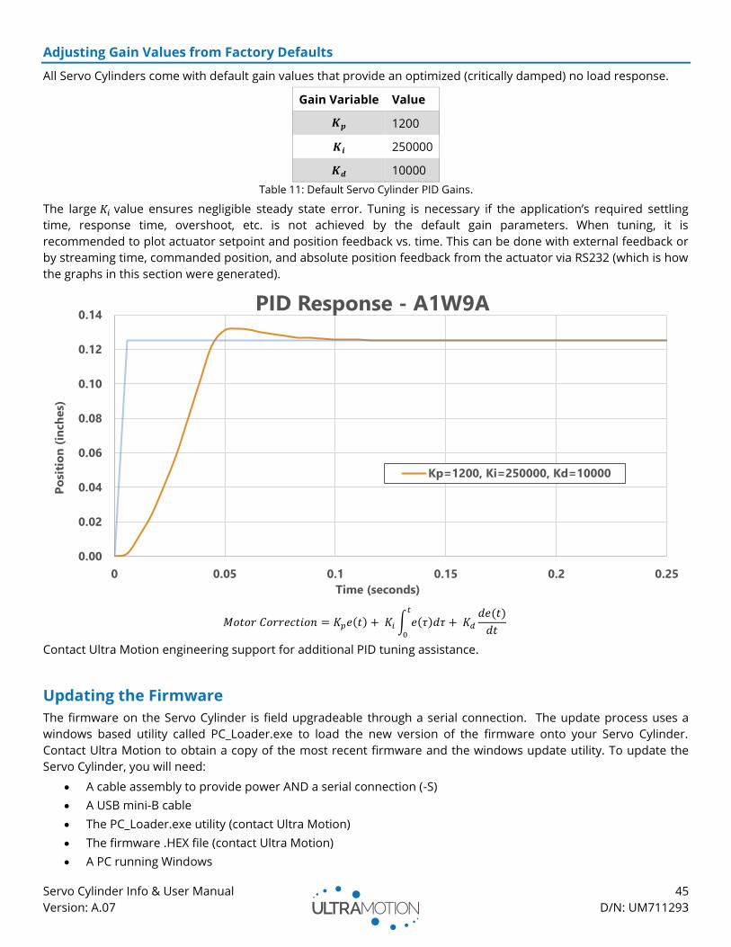
Servo Cylinder Info & User Manual 45
Version: A.07 D/N: UM711293
Adjusting Gain Values from Factory Defaults
All Servo Cylinders come with default gain values that provide an optimized (critically damped) no load response.
Gain Variable Value
𝑲𝒑 1200
𝑲𝒊 250000
𝑲𝒅 10000
Table 11: Default Servo Cylinder PID Gains.
The large 𝐾𝑖 value ensures negligible steady state error. Tuning is necessary if the application’s required settling
time, response time, overshoot, etc. is not achieved by the default gain parameters. When tuning, it is
recommended to plot actuator setpoint and position feedback vs. time. This can be done with external feedback or
by streaming time, commanded position, and absolute position feedback from the actuator via RS232 (which is how
the graphs in this section were generated).
𝑀𝑜𝑡𝑜𝑟 𝐶𝑜𝑟𝑟𝑒𝑐𝑡𝑖𝑜𝑛 = 𝐾𝑝𝑒(𝑡) + 𝐾𝑖 ∫ 𝑒(𝜏)𝑑𝜏𝑡
0
+ 𝐾𝑑
𝑑𝑒(𝑡)
𝑑𝑡
Contact Ultra Motion engineering support for additional PID tuning assistance.
Updating the Firmware
The firmware on the Servo Cylinder is field upgradeable through a serial connection. The update process uses a
windows based utility called PC_Loader.exe to load the new version of the firmware onto your Servo Cylinder.
Contact Ultra Motion to obtain a copy of the most recent firmware and the windows update utility. To update the
Servo Cylinder, you will need:
• A cable assembly to provide power AND a serial connection (-S)
• A USB mini-B cable
• The PC_Loader.exe utility (contact Ultra Motion)
• The firmware .HEX file (contact Ultra Motion)
• A PC running Windows
0.00
0.02
0.04
0.06
0.08
0.10
0.12
0.14
0 0.05 0.1 0.15 0.2 0.25
Po
siti
on
(in
ch
es)
Time (seconds)
PID Response - A1W9A
Kp=1200, Ki=250000, Kd=10000
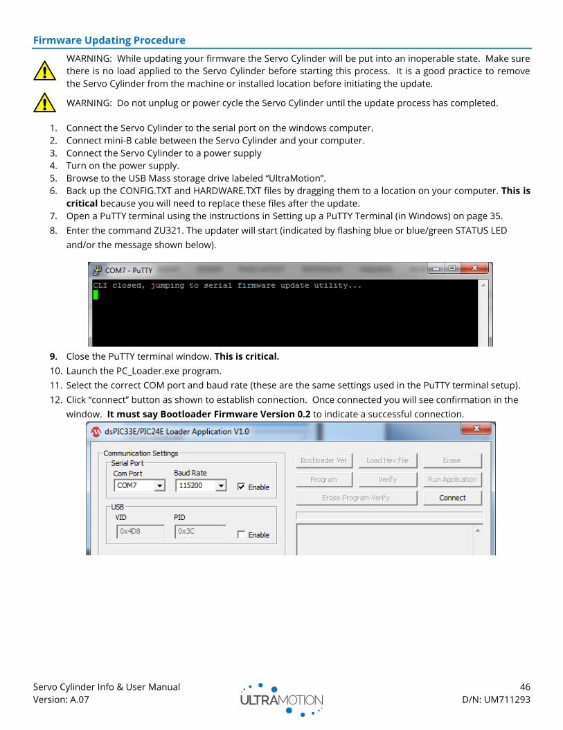
Servo Cylinder Info & User Manual 46
Version: A.07 D/N: UM711293
Firmware Updating Procedure
WARNING: While updating your firmware the Servo Cylinder will be put into an inoperable state. Make sure
there is no load applied to the Servo Cylinder before starting this process. It is a good practice to remove
the Servo Cylinder from the machine or installed location before initiating the update.
WARNING: Do not unplug or power cycle the Servo Cylinder until the update process has completed.
1. Connect the Servo Cylinder to the serial port on the windows computer.
2. Connect mini-B cable between the Servo Cylinder and your computer.
3. Connect the Servo Cylinder to a power supply
4. Turn on the power supply.
5. Browse to the USB Mass storage drive labeled “UltraMotion”.
6. Back up the CONFIG.TXT and HARDWARE.TXT files by dragging them to a location on your computer. This is
critical because you will need to replace these files after the update.
7. Open a PuTTY terminal using the instructions in Setting up a PuTTY Terminal (in Windows) on page 35.
8. Enter the command ZU321. The updater will start (indicated by flashing blue or blue/green STATUS LED
and/or the message shown below).
9. Close the PuTTY terminal window. This is critical.
10. Launch the PC_Loader.exe program.
11. Select the correct COM port and baud rate (these are the same settings used in the PuTTY terminal setup).
12. Click “connect” button as shown to establish connection. Once connected you will see confirmation in the
window. It must say Bootloader Firmware Version 0.2 to indicate a successful connection.

Servo Cylinder Info & User Manual 47
Version: A.07 D/N: UM711293
13. Once connected, click “Load Hex File”, and then navigate to the firmware file you would like to use for the
update (.hex file format). Click “Open”
14. Click on the “Erase-Program-Verify” button to start the update.
15. Once complete. You will see “programming complete” and “verification successful”. See screenshot below.
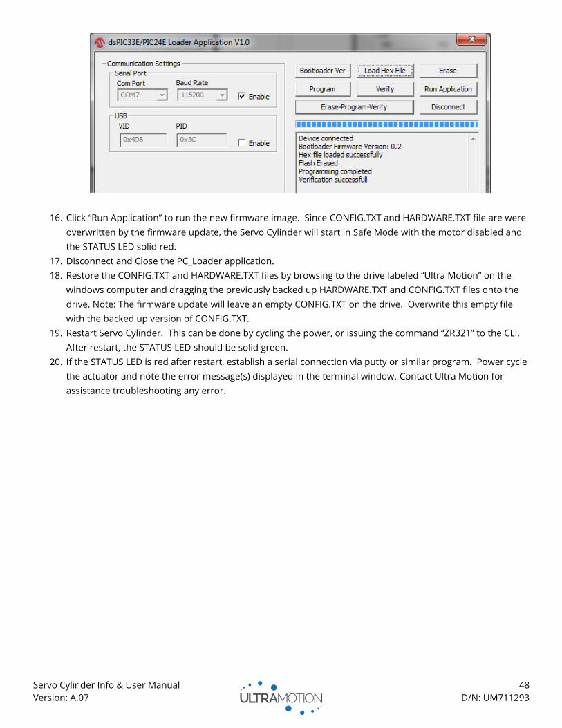
Servo Cylinder Info & User Manual 48
Version: A.07 D/N: UM711293
16. Click “Run Application” to run the new firmware image. Since CONFIG.TXT and HARDWARE.TXT file are were
overwritten by the firmware update, the Servo Cylinder will start in Safe Mode with the motor disabled and
the STATUS LED solid red.
17. Disconnect and Close the PC_Loader application.
18. Restore the CONFIG.TXT and HARDWARE.TXT files by browsing to the drive labeled “Ultra Motion” on the
windows computer and dragging the previously backed up HARDWARE.TXT and CONFIG.TXT files onto the
drive. Note: The firmware update will leave an empty CONFIG.TXT on the drive. Overwrite this empty file
with the backed up version of CONFIG.TXT.
19. Restart Servo Cylinder. This can be done by cycling the power, or issuing the command “ZR321” to the CLI.
After restart, the STATUS LED should be solid green.
20. If the STATUS LED is red after restart, establish a serial connection via putty or similar program. Power cycle
the actuator and note the error message(s) displayed in the terminal window. Contact Ultra Motion for
assistance troubleshooting any error.
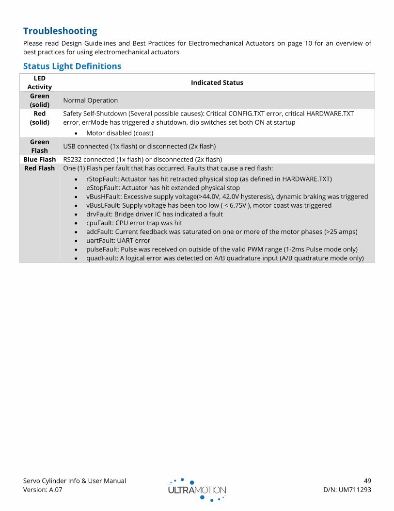
Servo Cylinder Info & User Manual 49
Version: A.07 D/N: UM711293
Troubleshooting
Please read Design Guidelines and Best Practices for Electromechanical Actuators on page 10 for an overview of
best practices for using electromechanical actuators
Status Light Definitions
LED
Activity Indicated Status
Green
(solid) Normal Operation
Red
(solid)
Safety Self-Shutdown (Several possible causes): Critical CONFIG.TXT error, critical HARDWARE.TXT
error, errMode has triggered a shutdown, dip switches set both ON at startup
• Motor disabled (coast)
Green
Flash USB connected (1x flash) or disconnected (2x flash)
Blue Flash RS232 connected (1x flash) or disconnected (2x flash)
Red Flash One (1) Flash per fault that has occurred. Faults that cause a red flash:
• rStopFault: Actuator has hit retracted physical stop (as defined in HARDWARE.TXT)
• eStopFault: Actuator has hit extended physical stop
• vBusHFault: Excessive supply voltage(>44.0V, 42.0V hysteresis), dynamic braking was triggered
• vBusLFault: Supply voltage has been too low ( < 6.75V ), motor coast was triggered
• drvFault: Bridge driver IC has indicated a fault
• cpuFault: CPU error trap was hit
• adcFault: Current feedback was saturated on one or more of the motor phases (>25 amps)
• uartFault: UART error
• pulseFault: Pulse was received on outside of the valid PWM range (1-2ms Pulse mode only)
• quadFault: A logical error was detected on A/B quadrature input (A/B quadrature mode only)
Servo Cylinder Info & User Manual 50
Version: A.07 D/N: UM711293
Appendix A: Serial Command Line Interface (CLI) List of Commands Read Commands ................................................................................................................................................................................... 51
AN – Read Analog Inputs ............................................................................................................................................................................ 51 AP – Read Actuator Position ....................................................................................................................................................................... 51 BV – Read Bus Voltage ................................................................................................................................................................................ 51 DI – Read Digital Input ................................................................................................................................................................................ 51 FS – Read Firmware Version and Serial Number ..................................................................................................................................... 51 HE – Display the Help Table ....................................................................................................................................................................... 51 QP – Read Position Setpoint....................................................................................................................................................................... 51 RC – Read 1 to 2ms Pulse (PWM) Input ..................................................................................................................................................... 52 SR – Read Status Register ........................................................................................................................................................................... 52 TQ – Read Motor Torque ............................................................................................................................................................................ 52 VL – Read Actuator Velocity ........................................................................................................................................................................ 52
Set Commands ....................................................................................................................................................................................... 52
AC – Set Acceleration for Trajectory Moves ............................................................................................................................................. 52 CG – Coast On .............................................................................................................................................................................................. 52 CS – Coast Off............................................................................................................................................................................................... 52 D1, D2 – Set Mode for DIO1 and DIO2 (Respectively) ............................................................................................................................. 53 H1, H2 – Set the PWM Output Signal Type on DIO1 and DIO2 (Respectively)...................................................................................... 53 IM – Set Serial Interface Mode ................................................................................................................................................................... 53 KP – Set Proportional Gain for Position PID Filter ................................................................................................................................... 54 KI - Set Integral Gain for Position PID Filter .............................................................................................................................................. 54 KD - Set Derivative Gain for Position PID Filter ........................................................................................................................................ 54 MT – Set Limit for Maximum Commanded Torque ................................................................................................................................. 54 PA – Set Absolute Target Position ............................................................................................................................................................. 54 PC – Set Target Position to Current Position ............................................................................................................................................ 54 PO – Set Target Position Offset .................................................................................................................................................................. 54 SP – Set Maximum Speed for Trajectory Moves ...................................................................................................................................... 55 W1, W2 – Set Status Register Bit Mask for GPIOs DIO1 and DIO2 (Respectively) ................................................................................ 55
System Commands ............................................................................................................................................................................... 55
ZC – Run Calibration Routine ..................................................................................................................................................................... 55 ZD– Read Bridge Driver DIAG Register ..................................................................................................................................................... 55 ZF – Clear Latching Fault Flags in Status Register .................................................................................................................................... 55 ZR – Reset Actuator ..................................................................................................................................................................................... 55 ZU – Jump to RS232 Firmware Updater .................................................................................................................................................... 56
Trajectory Commands .......................................................................................................................................................................... 56
T1, T2, T3, T4 – Trajectory Move to User Defined Position Pos1, Pos2, Pos3, and Pos4 (Respectively) ............................................ 56 TA – Trajectory Move to Absolute Position ............................................................................................................................................... 56 TE – Trajectory Move to Fully Extended Position (spMax) ...................................................................................................................... 56 TK – Interrupt the current trajectory ......................................................................................................................................................... 56 TM – Trajectory Move to Midpoint ............................................................................................................................................................ 57 TO – Trajectory Move to Offset (incremental trajectory move) ............................................................................................................. 57 TR – Trajectory Move to Fully Retracted Position (spMin) ...................................................................................................................... 57
Serial Data Streaming .......................................................................................................................................................................... 58
X1, X2, X3 – Set Data Stream for Columns 1, 2, and 3 (respectively) ..................................................................................................... 58 XC – Clear Timer........................................................................................................................................................................................... 58 XG – Turn Data Streaming On .................................................................................................................................................................... 58 XR – Display Data Stream Setup ................................................................................................................................................................ 58 XS – Turn Data Streaming Off .................................................................................................................................................................... 58 XT – Set Data Stream Time Interval ........................................................................................................................................................... 59
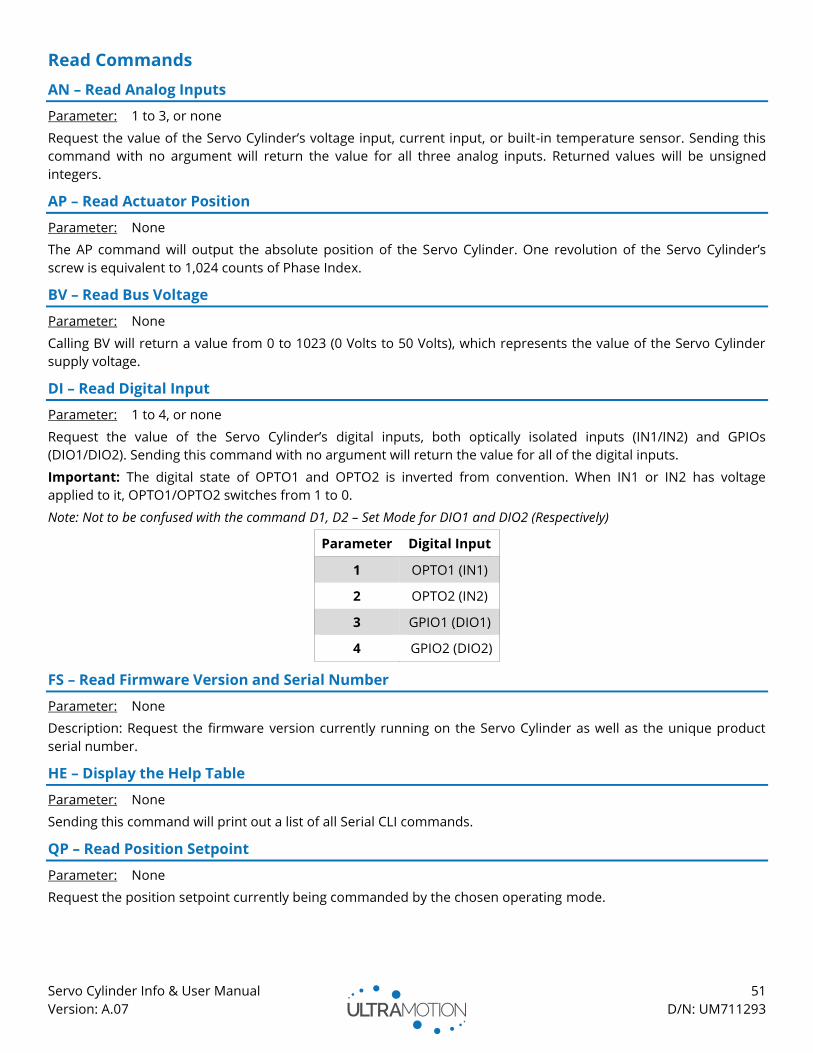
Servo Cylinder Info & User Manual 51
Version: A.07 D/N: UM711293
Read Commands
AN – Read Analog Inputs
Parameter: 1 to 3, or none
Request the value of the Servo Cylinder’s voltage input, current input, or built-in temperature sensor. Sending this
command with no argument will return the value for all three analog inputs. Returned values will be unsigned
integers.
AP – Read Actuator Position
Parameter: None
The AP command will output the absolute position of the Servo Cylinder. One revolution of the Servo Cylinder’s
screw is equivalent to 1,024 counts of Phase Index.
BV – Read Bus Voltage
Parameter: None
Calling BV will return a value from 0 to 1023 (0 Volts to 50 Volts), which represents the value of the Servo Cylinder
supply voltage.
DI – Read Digital Input
Parameter: 1 to 4, or none
Request the value of the Servo Cylinder’s digital inputs, both optically isolated inputs (IN1/IN2) and GPIOs
(DIO1/DIO2). Sending this command with no argument will return the value for all of the digital inputs.
Important: The digital state of OPTO1 and OPTO2 is inverted from convention. When IN1 or IN2 has voltage
applied to it, OPTO1/OPTO2 switches from 1 to 0.
Note: Not to be confused with the command D1, D2 – Set Mode for DIO1 and DIO2 (Respectively)
Parameter Digital Input
1 OPTO1 (IN1)
2 OPTO2 (IN2)
3 GPIO1 (DIO1)
4 GPIO2 (DIO2)
FS – Read Firmware Version and Serial Number
Parameter: None
Description: Request the firmware version currently running on the Servo Cylinder as well as the unique product
serial number.
HE – Display the Help Table
Parameter: None
Sending this command will print out a list of all Serial CLI commands.
QP – Read Position Setpoint
Parameter: None
Request the position setpoint currently being commanded by the chosen operating mode.
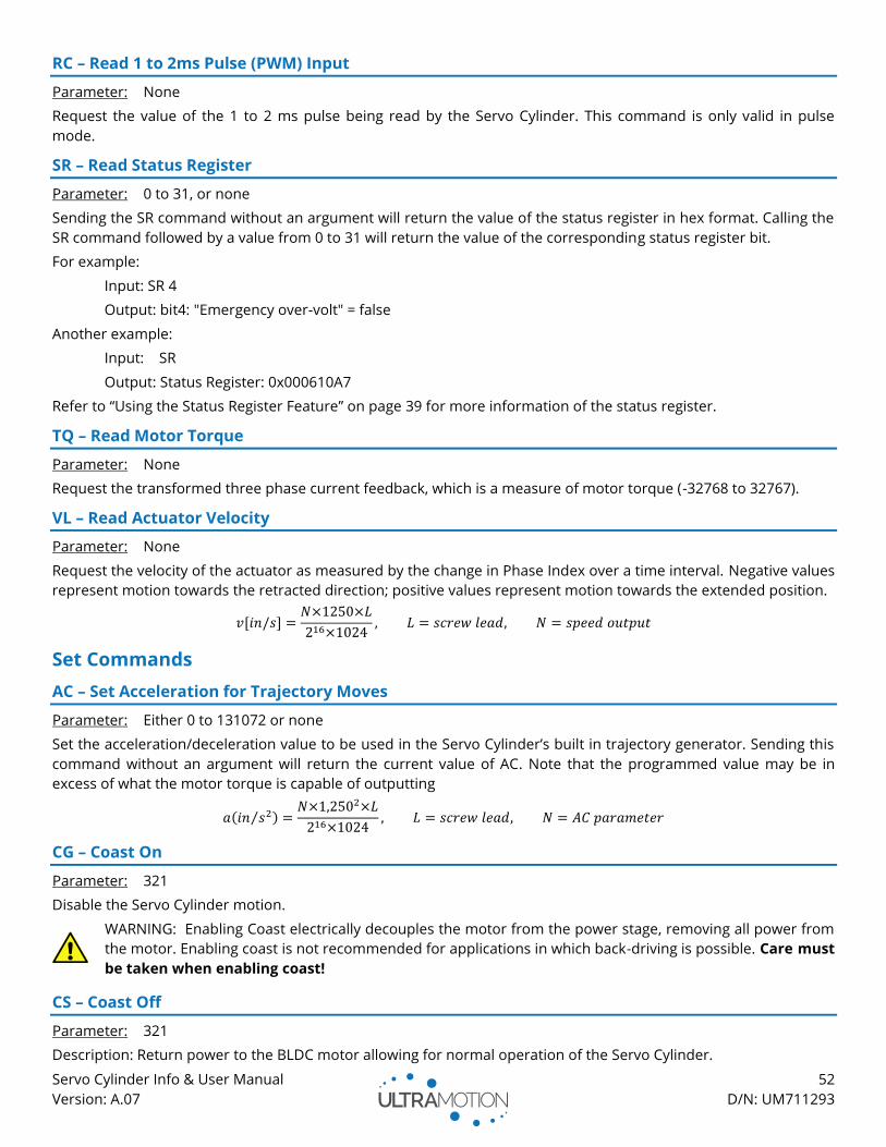
Servo Cylinder Info & User Manual 52
Version: A.07 D/N: UM711293
RC – Read 1 to 2ms Pulse (PWM) Input
Parameter: None
Request the value of the 1 to 2 ms pulse being read by the Servo Cylinder. This command is only valid in pulse
mode.
SR – Read Status Register
Parameter: 0 to 31, or none
Sending the SR command without an argument will return the value of the status register in hex format. Calling the
SR command followed by a value from 0 to 31 will return the value of the corresponding status register bit.
For example:
Input: SR 4
Output: bit4: "Emergency over-volt" = false
Another example:
Input: SR
Output: Status Register: 0x000610A7
Refer to “Using the Status Register Feature” on page 39 for more information of the status register.
TQ – Read Motor Torque
Parameter: None
Request the transformed three phase current feedback, which is a measure of motor torque (-32768 to 32767).
VL – Read Actuator Velocity
Parameter: None
Request the velocity of the actuator as measured by the change in Phase Index over a time interval. Negative values
represent motion towards the retracted direction; positive values represent motion towards the extended position.
𝑣[𝑖𝑛/𝑠] =𝑁×1250×𝐿
216×1024, 𝐿 = 𝑠𝑐𝑟𝑒𝑤 𝑙𝑒𝑎𝑑, 𝑁 = 𝑠𝑝𝑒𝑒𝑑 𝑜𝑢𝑡𝑝𝑢𝑡
Set Commands
AC – Set Acceleration for Trajectory Moves
Parameter: Either 0 to 131072 or none
Set the acceleration/deceleration value to be used in the Servo Cylinder’s built in trajectory generator. Sending this
command without an argument will return the current value of AC. Note that the programmed value may be in
excess of what the motor torque is capable of outputting
𝑎(𝑖𝑛 𝑠2⁄ ) =𝑁×1,2502×𝐿
216×1024, 𝐿 = 𝑠𝑐𝑟𝑒𝑤 𝑙𝑒𝑎𝑑, 𝑁 = 𝐴𝐶 𝑝𝑎𝑟𝑎𝑚𝑒𝑡𝑒𝑟
CG – Coast On
Parameter: 321
Disable the Servo Cylinder motion.
WARNING: Enabling Coast electrically decouples the motor from the power stage, removing all power from
the motor. Enabling coast is not recommended for applications in which back-driving is possible. Care must
be taken when enabling coast!
CS – Coast Off
Parameter: 321
Description: Return power to the BLDC motor allowing for normal operation of the Servo Cylinder.
Servo Cylinder Info & User Manual 53
Version: A.07 D/N: UM711293
WARNING: Re-energizing the motor will cause the Servo Cylinder to immediately move to the current
commanded position. Care must be taken when disabling Coast!
D1, D2 – Set Mode for DIO1 and DIO2 (Respectively)
Parameter: 0 to 4, or none
Set the function of the Servo Cylinder’s General Purpose Input / Output (GPIO) pins (DIO1 and DIO2). Sending this
command without an argument will return the current programmed value.
Note: Not to be confused with the command DI – Read Digital Input
Parameter DIO Pin Function
0 Input (high impedance)
1 Ground (sink up to 250 mA)
2 Output +5 Volts (source up to 250 mA)
3 Output Status Bit (see Refer to “Using the Status Register Feature” on page 39)
4 Output 1 kHz +5 V PWM (See H1, H2 – Set the PWM Output Signal Type on DIO1 and DIO2
(Respectively) )
H1, H2 – Set the PWM Output Signal Type on DIO1 and DIO2 (Respectively)
Parameter: 0 to 7, or none
Rules: D1 and/or D2 = 4
The value assigned to H1 represents the source for the PWM duty cycle. All source ranges are converted to the PWM
duty cycle range of 0 to 60,000. Sending this command without an argument will return the current value.
Parameter Output Signal Type Range
0 Actuator Position spMin to spMax
1 Actuator Velocity -512 to 511
2 Actuator Torque -32768 to 32767
3 Bus Voltage 0 to 1023
4 Commanded Position spMin to spMax
5 1 to 2ms Pulse (PWM) input channel pMin to pMax
6 Analog voltage input vMin to vMax
7 Analog current input cMin to cMax
IM – Set Serial Interface Mode
Parameter: 0 or 1
The serial interface can be set to operate in “Human Mode” or “Machine Mode”
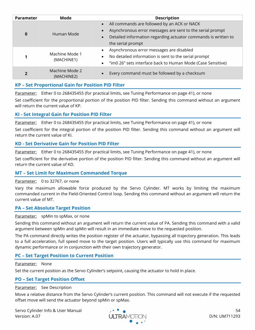
Servo Cylinder Info & User Manual 54
Version: A.07 D/N: UM711293
Parameter Mode Description
0 Human Mode
• All commands are followed by an ACK or NACK
• Asynchronous error messages are sent to the serial prompt
• Detailed information regarding actuator commands is written to
the serial prompt
1 Machine Mode 1
(MACHINE1)
• Asynchronous error messages are disabled
• No detailed information is sent to the serial prompt
• ”im0 26” sets interface back to Human Mode (Case Sensitive)
2 Machine Mode 2
(MACHINE2) • Every command must be followed by a checksum
KP – Set Proportional Gain for Position PID Filter
Parameter: Either 0 to 268435455 (for practical limits, see Tuning Performance on page 41), or none
Set coefficient for the proportional portion of the position PID filter. Sending this command without an argument
will return the current value of KP.
KI - Set Integral Gain for Position PID Filter
Parameter: Either 0 to 268435455 (for practical limits, see Tuning Performance on page 41), or none
Set coefficient for the integral portion of the position PID filter. Sending this command without an argument will
return the current value of KI.
KD - Set Derivative Gain for Position PID Filter
Parameter: Either 0 to 268435455 (for practical limits, see Tuning Performance on page 41), or none
Set coefficient for the derivative portion of the position PID filter. Sending this command without an argument will
return the current value of KD.
MT – Set Limit for Maximum Commanded Torque
Parameter: 0 to 32767, or none
Vary the maximum allowable force produced by the Servo Cylinder. MT works by limiting the maximum
commanded current in the Field-Oriented Control loop. Sending this command without an argument will return the
current value of MT.
PA – Set Absolute Target Position
Parameter: spMin to spMax, or none
Sending this command without an argument will return the current value of PA. Sending this command with a valid
argument between spMin and spMin will result in an immediate move to the requested position.
The PA command directly writes the position register of the actuator, bypassing all trajectory generation. This leads
to a full acceleration, full speed move to the target position. Users will typically use this command for maximum
dynamic performance or in conjunction with their own trajectory generator.
PC – Set Target Position to Current Position
Parameter: None
Set the current position as the Servo Cylinder’s setpoint, causing the actuator to hold in place.
PO – Set Target Position Offset
Parameter: See Description
Move a relative distance from the Servo Cylinder’s current position. This command will not execute if the requested
offset move will send the actuator beyond spMin or spMax.
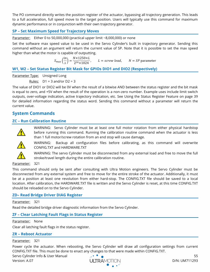
Servo Cylinder Info & User Manual 55
Version: A.07 D/N: UM711293
The PO command directly writes the position register of the actuator, bypassing all trajectory generation. This leads
to a full acceleration, full speed move to the target position. Users will typically use this command for maximum
dynamic performance or in conjunction with their own trajectory generator.
SP – Set Maximum Speed for Trajectory Moves
Parameter: Either 0 to 50,000,000 (practical upper limit ~8,000,000) or none
Set the software max speed value to be used in the Servo Cylinder’s built in trajectory generator. Sending this
command without an argument will return the current value of SP. Note that it is possible to set the max speed
higher than what the motor is capable of outputting.
𝑆𝑚𝑎𝑥 (𝑖𝑛
𝑠) =
𝑁×1250×𝐿
216×1024, 𝐿 = 𝑠𝑐𝑟𝑒𝑤 𝑙𝑒𝑎𝑑, 𝑁 = 𝑆𝑃 parameter
W1, W2 – Set Status Register Bit Mask for GPIOs DIO1 and DIO2 (Respectively)
Parameter Type: Unsigned Long
Rules: D1 = 3 and/or D2 = 3
The value of DIO1 or DIO2 will be 0V when the result of a bitwise AND between the status register and the bit mask
is equal to zero, and +5V when the result of the operation is a non-zero number. Example uses include limit switch
outputs, over-voltage indication, active trajectory indication, etc. See Using the Status Register Feature on page 39
for detailed information regarding the status word. Sending this command without a parameter will return the
current value.
System Commands
ZC – Run Calibration Routine
WARNING: Servo Cylinder must be at least one full motor rotation from either physical hardstop
before running this command. Running the calibration routine command when the actuator is less
than 1 full motor/screw rotation from an end stop will cause damage.
WARNING: Backup all configuration files before calibrating, as this command will overwrite
CONFIG.TXT and HARDWARE.TXT
WARNING: The servo Cylinder must be disconnected from any external load and free to move the full
stroke/travel length during the entire calibration routine.
Parameter: 321
This command should only be sent after consulting with Ultra Motion engineers. The Servo Cylinder must be
disconnected from any external system and free to move for the entire stroke of the actuator. Additionally, it must
be at a position at least one revolution from either hard-stop. The CONFIG.TXT file should be saved to a local
location. After calibration, the HARDWARE.TXT file is written and the Servo Cylinder is reset, at this time CONFIG.TXT
should be reloaded on to the Servo Cylinder.
ZD– Read Bridge Driver DIAG Register
Parameter: 321
Read the detailed bridge driver diagnostic information from the Servo Cylinder.
ZF – Clear Latching Fault Flags in Status Register
Parameter: None
Clear all latching fault flags in the status register.
ZR – Reboot Actuator
Parameter: 321
Power cycle the actuator. When rebooting, the Servo Cylinder will draw all configuration settings from current
CONFIG.TXT file. This must be done to enact any changes to that were made within CONFIG.TXT.

Servo Cylinder Info & User Manual 56
Version: A.07 D/N: UM711293
ZU – Jump to RS232 Firmware Updater
Parameter: 321
Suspend normal operation of the Servo Cylinder and launch the on-board bootloader to update the firmware. The
actuator should be removed/disconnected from the machine to prevent potential damages and must be
disconnected from USB.
ZW – Write current settings to CONFIG.TXT
Parameter: 321
This command will take all current operational settings and write them to CONFIG.TXT. This must be done if a
setting was changed via a serial command, and you wish to retain this change after a reboot.
WARNING: Running this command will strip CONFIG.TXT of all comments. Back up CONFIG.TXT before
running this command to not lose this information.
Trajectory Commands
Trajectory commands are used to smoothly move the actuator to a desired position using the user configurable
max speed and acceleration.
T1, T2, T3, T4 – Trajectory Move to User Defined Position Pos1, Pos2, Pos3, and Pos4 (Respectively)
Parameter: None
Move to Pos1, Pos2, Pos3, or Pos4 with user defined speed and acceleration (Pos1 through Pos4 defined in
CONFIG.TXT).
Command Position
T1 Pos1
T2 Pos2
T3 Pos3
T4 Pos4
TA – Trajectory Move to Absolute Position
Parameter: spMin to spMax
Sending this command with a valid argument between spMin and spMin will result in a trajectory move to the
requested position.
Example: Move to absolute position 25,000 with acceleration value 2,000 and speed 200,000:
AC2000
SP200000
TA25000
TE – Trajectory Move to Fully Extended Position (spMax)
Parameter: None
Move to spMax with user defined speed and acceleration.
TK – Interrupt the current trajectory
Parameter: None
Halt the current trajectory motion before completion.
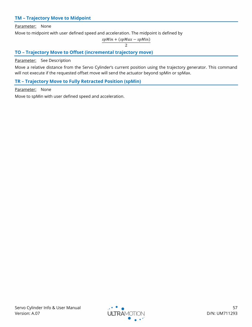
Servo Cylinder Info & User Manual 57
Version: A.07 D/N: UM711293
TM – Trajectory Move to Midpoint
Parameter: None
Move to midpoint with user defined speed and acceleration. The midpoint is defined by
𝑠𝑝𝑀𝑖𝑛 + (𝑠𝑝𝑀𝑎𝑥 − 𝑠𝑝𝑀𝑖𝑛)
2
TO – Trajectory Move to Offset (incremental trajectory move)
Parameter: See Description
Move a relative distance from the Servo Cylinder’s current position using the trajectory generator. This command
will not execute if the requested offset move will send the actuator beyond spMin or spMax.
TR – Trajectory Move to Fully Retracted Position (spMin)
Parameter: None
Move to spMin with user defined speed and acceleration.

Servo Cylinder Info & User Manual 58
Version: A.07 D/N: UM711293
Serial Data Streaming
X1, X2, X3 – Set Data Stream for Columns 1, 2, and 3 (respectively)
Parameter: 0 to 23
Define what variable each of the three columns are reporting
Parameter Description
0 Column Off
1 Actuator Position
2 Position Command Setpoint
3 Motor Current
4 Motor Current Setpoint
5 Motor Phase 1 Current
6 Motor Phase 2 Current
7 Motor Phase 3 Current
8 Actuator Velocity at 312.5 kHz
9 Actuator Velocity at 78.125 Hz
10 Encoder Interval Timer
11 Supply Voltage
12 Status Bit Register
13 1 to 2 ms pulse (PWM) Input
14 Filtered 1 to 2 ms pulse (PWM) Input
15 Analog Voltage Input
16 Filtered Analog Voltage Input
17 Analog Current Input
18 Filtered Analog Current Input
19 Temperature Sensor Input
20 Position Error
21 Quadrature Input Errors
22 1 to 2 ms pulse (PWM) input errors
23 32-bit Timer with 100 µs Increments
XC – Clear Timer
Parameter: None
Reset the 32 bit timer used for synchronizing data to a time interval.
XG – Turn Data Streaming On
Parameter: None
Initiate data streaming.
XR – Display Data Stream Setup
Parameter: None
Display the current stream setup including what variables are being streamed and streaming frequency.
XS – Turn Data Streaming Off
Parameter: None
Stop the data streaming.
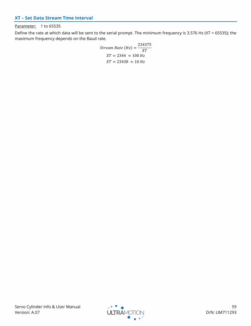
Servo Cylinder Info & User Manual 59
Version: A.07 D/N: UM711293
XT – Set Data Stream Time Interval
Parameter: 1 to 65535
Define the rate at which data will be sent to the serial prompt. The minimum frequency is 3.576 Hz (XT = 65535); the
maximum frequency depends on the Baud rate.
𝑆𝑡𝑟𝑒𝑎𝑚 𝑅𝑎𝑡𝑒 (𝐻𝑧) =234375
𝑋𝑇
𝑋𝑇 = 2344 ≈ 100 𝐻𝑧
𝑋𝑇 = 23438 ≈ 10 𝐻𝑧

Servo Cylinder Info & User Manual 60
Version: A.07 D/N: UM711293
Appendix B: Firmware Changelog
Version
Number Description
0.958
May 5, 2017 • Fixed bugs related to range checking in “sp” command and “ifMode” variable.
0.957
April 27, 2017
• Update to new compiler version.
• Corrected help table information on data streaming.
0.956
May 19, 2016
• First public release. For users with prior versions, contact Ultra Motion for more
information on firmware changes.
Servo Cylinder Info & User Manual 61
Version: A.07 D/N: UM711293
Contact Information
If you have any questions about the Servo Cylinder or any of our other products, contact us by one of the following
methods:
INQUIRY
Leave a web inquiry (to be replied to within one business day):
ultramotion.com/contact
LIVE CHAT
Live Chat directly with one of our engineers:
ultramotion.com
Email (to be replied to within one business day):
CALL
PH: 888-321-9178
Fax: 631-298-6593
ADDRESS
Ultra Motion
22355 CR 48, #21
Cutchogue, NY 11935
HOURS
Our Business Hours:
Monday-Friday
9AM – 5PM EST