Embed Size (px)
Citation preview

Manual No. 100-5316-01 Rev. 3
401/402XR Series Product Manual Effective: November 17, 2004 Supersedes: February 27, 2002
Electromechanical Positioning Systems
401/402XR Series Product Manual
2 www.parkermotion.com
Parker Hannifin Corporation 1140 Sandy Hill Road Irwin, PA 15642
Important User Information
The information in the product manual, including any apparatus, methods, techniques, and concepts described herein, are the proprietary property of Parker Hannifin Corporation or its licensors, and may not be copied, disclosed, or used for any purpose not expressly authorized by the owner thereof. Since Parker Hannifin Corporation constantly strives to improve all of its products, we reserve the right to change this product manual and equipment mentioned therein at any time without notice.
For assistance contact: Parker Hannifin Corporation 1140 Sandy Hill Road Irwin, PA 15642 Phone: 724/861-8200 800/245-6903 Fax: 724/861-3330 E-mail: [email protected] Web site: www.parkermotion.com
401/402XR Series Product Manual
3 www.parkermotion.com
Parker Hannifin Corporation 1140 Sandy Hill Road Irwin, PA 15642
401/402XR Series Product Manual
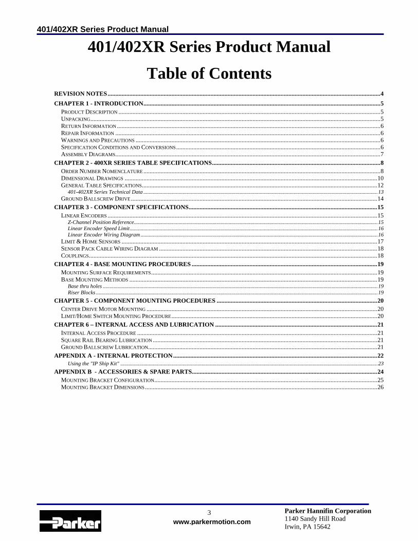
Table of Contents
REVISION NOTES...............................................................................................................................................................................4 CHAPTER 1 - INTRODUCTION........................................................................................................................................................5
PRODUCT DESCRIPTION ........................................................................................................................................................................5 UNPACKING..........................................................................................................................................................................................5 RETURN INFORMATION .........................................................................................................................................................................6 REPAIR INFORMATION ..........................................................................................................................................................................6 WARNINGS AND PRECAUTIONS .............................................................................................................................................................6 SPECIFICATION CONDITIONS AND CONVERSIONS...................................................................................................................................6 ASSEMBLY DIAGRAMS..........................................................................................................................................................................7
CHAPTER 2 - 400XR SERIES TABLE SPECIFICATIONS............................................................................................................8 ORDER NUMBER NOMENCLATURE ........................................................................................................................................................8 DIMENSIONAL DRAWINGS ..................................................................................................................................................................10 GENERAL TABLE SPECIFICATIONS.......................................................................................................................................................12
401-402XR Series Technical Data .............................................................................................................................................................................13 GROUND BALLSCREW DRIVE..............................................................................................................................................................14
CHAPTER 3 - COMPONENT SPECIFICATIONS.........................................................................................................................15 LINEAR ENCODERS .............................................................................................................................................................................15
Z-Channel Position Reference....................................................................................................................................................................................15 Linear Encoder Speed Limit.......................................................................................................................................................................................16 Linear Encoder Wiring Diagram ...............................................................................................................................................................................16
LIMIT & HOME SENSORS ....................................................................................................................................................................17 SENSOR PACK CABLE WIRING DIAGRAM ............................................................................................................................................18 COUPLINGS.........................................................................................................................................................................................18
CHAPTER 4 - BASE MOUNTING PROCEDURES .......................................................................................................................19 MOUNTING SURFACE REQUIREMENTS.................................................................................................................................................19 BASE MOUNTING METHODS ...............................................................................................................................................................19
Base thru holes ...........................................................................................................................................................................................................19 Riser Blocks ................................................................................................................................................................................................................19
CHAPTER 5 - COMPONENT MOUNTING PROCEDURES .......................................................................................................20 CENTER DRIVE MOTOR MOUNTING ....................................................................................................................................................20 LIMIT/HOME SWITCH MOUNTING PROCEDURE....................................................................................................................................20
CHAPTER 6 – INTERNAL ACCESS AND LUBRICATION ........................................................................................................21 INTERNAL ACCESS PROCEDURE ..........................................................................................................................................................21 SQUARE RAIL BEARING LUBRICATION ................................................................................................................................................21 GROUND BALLSCREW LUBRICATION...................................................................................................................................................21
APPENDIX A - INTERNAL PROTECTION...................................................................................................................................22 Using the "IP Ship Kit" ..............................................................................................................................................................................................23
APPENDIX B - ACCESSORIES & SPARE PARTS.......................................................................................................................24 MOUNTING BRACKET CONFIGURATION...............................................................................................................................................25 MOUNTING BRACKET DIMENSIONS.....................................................................................................................................................26

401/402XR Series Product Manual Revision Notes
4 www.parkermotion.com
Parker Hannifin Corporation 1140 Sandy Hill Road Irwin, PA 15642
Revision Notes Rev. 2 – Effective February 27, 2002 – Added Revision Notes, added precision information, updated order
number nomenclature, updated dimensional drawings, updated accessories & spare parts, updated mounting bracket configurations, updated mounting bracket dimensions.
Rev 3 – Effective November 17, 2004 – Modified Limit & Home Sensors section to include new 4 wire sensor.
Updated sensor pack cable diagram for Limit 1 and Limit 2. Changed all logos to Parker only. Changed web address to www.parkermotion.com and removed division name from company address.
401/402XR Series Product Manual Chapter 1 - Introduction
5 www.parkermotion.com
Parker Hannifin Corporation 1140 Sandy Hill Road Irwin, PA 15642
Chapter 1 - Introduction
Product Description
401XR and 402XR Positioners The 401XR and 402XR “Mini” Series positioners enhance the 400XR family of precision linear positioners, addressing applications that involve precise positioning of smaller payloads within a very small space envelope. These ballscrew driven positioners were developed to address the needs of industries such as photonics, life sciences, semiconductor, and instrumentation, where technology advancements dictate miniaturization of work envelopes. 400XR Product Family ‘Modular Flexibility’ is the attribute that clearly distinguishes the 400XR family of linear tables from all others. This product family allows each unit to be easily configured to meet unique requirements, from the very basic to the highly complex. Field upgrades and redesigns are easily accommodated; simply follow the mounting procedure that ships with the desired assembly or individual part. This compatible family of positioners offers reliable accuracy, versatility and strength. Adapters and brackets make it easy to combine 401XR and 402XR positioners, as required, to form multi-axis systems without special design or manufacturing. The 400XR family of products are rugged enough to perform well in the industrial automation environment (automotive, packaging) and yet they’re precise enough to excel in the high end semi-conductor and instrumentation markets.
Unpacking
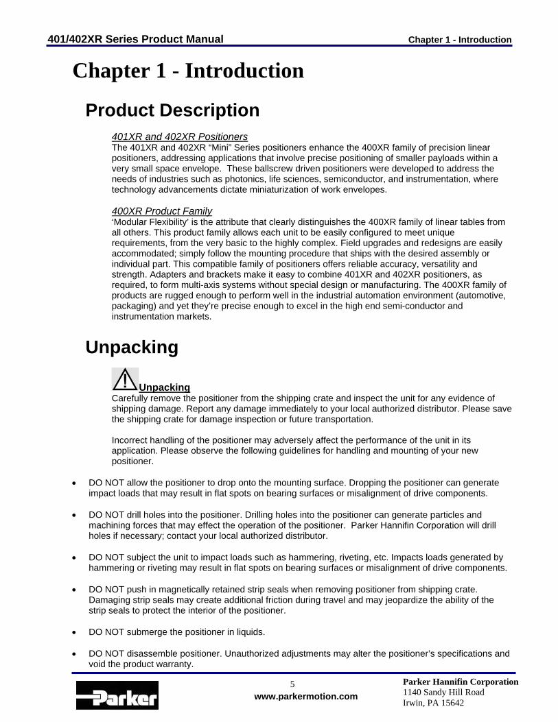
Unpacking Carefully remove the positioner from the shipping crate and inspect the unit for any evidence of shipping damage. Report any damage immediately to your local authorized distributor. Please save the shipping crate for damage inspection or future transportation. Incorrect handling of the positioner may adversely affect the performance of the unit in its application. Please observe the following guidelines for handling and mounting of your new positioner.
• DO NOT allow the positioner to drop onto the mounting surface. Dropping the positioner can generate impact loads that may result in flat spots on bearing surfaces or misalignment of drive components.
• DO NOT drill holes into the positioner. Drilling holes into the positioner can generate particles and
machining forces that may effect the operation of the positioner. Parker Hannifin Corporation will drill holes if necessary; contact your local authorized distributor.
• DO NOT subject the unit to impact loads such as hammering, riveting, etc. Impacts loads generated by
hammering or riveting may result in flat spots on bearing surfaces or misalignment of drive components. • DO NOT push in magnetically retained strip seals when removing positioner from shipping crate.
Damaging strip seals may create additional friction during travel and may jeopardize the ability of the strip seals to protect the interior of the positioner.
• DO NOT submerge the positioner in liquids. • DO NOT disassemble positioner. Unauthorized adjustments may alter the positioner’s specifications and
void the product warranty.
401/402XR Series Product Manual Chapter 1 - Introduction
6 www.parkermotion.com
Parker Hannifin Corporation 1140 Sandy Hill Road Irwin, PA 15642
Return Information
Returns All returns must reference a “Return Material Authorization”, (RMA), number. Please call your local authorized distributor or Parker Hannifin Corporation Customer Service Department at 800-245-6903 to obtain a “RMA” number. See Parker Hannifin Corporation Catalog #8080/USA, page D34, for additional information on returns and warranty.
Repair Information
Out-of-Warranty Repair Our Customer Service Department repairs Out-of-Warranty products. All returns must reference a “RMA” number. Please call your local authorized distributor or Parker Hannifin Corporation Customer Service Department at 800-245-6903 to obtain a “RMA” number. You will be notified of any cost prior to making the repair.
Warnings and Precautions
Vertical Operation Depending upon your load and ballscrew selection the carriage and load may ‘backdrive’ in power loss situations potentially causing product damage or personal injury.
Strain Relieve Electrical Components All electrical components (such as brakes, encoders, and limit/home switches) must be strain relieved. Failure to strain relieve electrical wires or cables may result in component failure and/or possible personal injury.
Specification Conditions and Conversions
Specifications are Temperature Dependent Catalog Specifications are obtained and measured at 20 Degrees C. Specifications at any other temperature may deviate from catalog specifications. Minimum to Maximum continuous operating temperature range (with NO guarantee of any specification except motion) of a standard unit before failure is 5 - 70 Degrees C. Certain components can be eliminated or substituted to improve operation at these temperatures. Positioners with low temperature or high temperature components will be handled as specials, contact your local distributor. Specifications are Mounting Surface Dependent Catalog Specifications are obtained and measured when the positioner is fully supported, bolted down (to eliminate any extrusion deviation), and is mounted to a work surface that has a maximum flatness error of 0.013mm/300mm (0.0005”/ft). Specifications are Point of Measurement Dependent Catalog Specifications and Specifications in this manual are measured in the center of the carriage, 37.5mm above the carriage surface. All measurements taken at any other location may deviate from these values.
401/402XR Series Product Manual Chapter 1 - Introduction
7 www.parkermotion.com
Parker Hannifin Corporation 1140 Sandy Hill Road Irwin, PA 15642
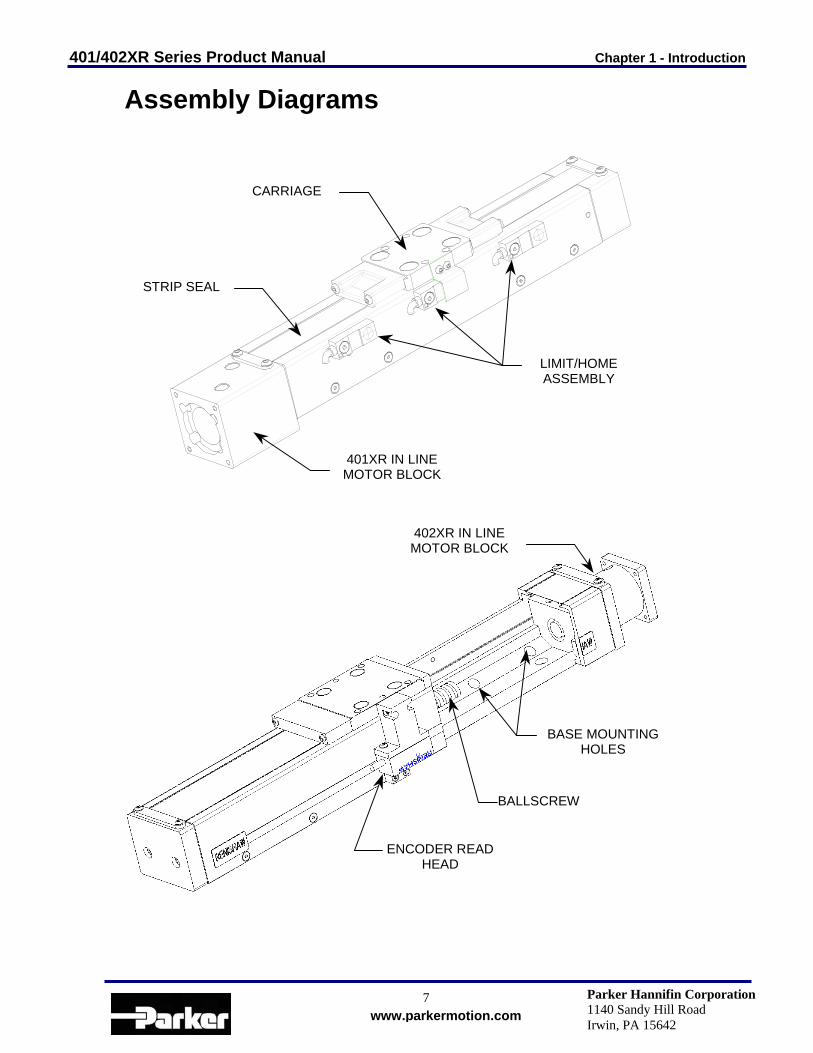
Assembly Diagrams
401XR IN LINEMOTOR BLOCK
LIMIT/HOMEASSEMBLY
STRIP SEAL
CARRIAGE
BALLSCREW
BASE MOUNTINGHOLES
402XR IN LINEMOTOR BLOCK
ENCODER READHEAD
401/402XR Series Product Manual Chapter 2 - 401/402XR Series Table Specifications
8 www.parkermotion.com
Parker Hannifin Corporation 1140 Sandy Hill Road Irwin, PA 15642
Chapter 2 - 400XR Series Table Specifications
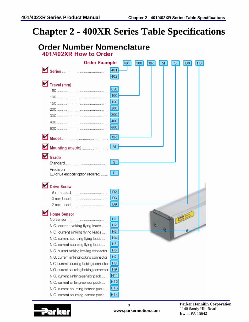
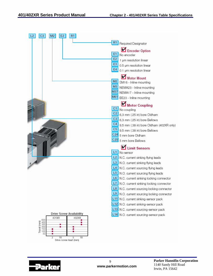
Order Number Nomenclature
401/402XR Series Product Manual Chapter 2 - 401/402XR Series Table Specifications
9 www.parkermotion.com
Parker Hannifin Corporation 1140 Sandy Hill Road Irwin, PA 15642

401/402XR Series Product Manual Chapter 2 - 401/402XR Series Table Specifications
10 www.parkermotion.com
Parker Hannifin Corporation 1140 Sandy Hill Road Irwin, PA 15642
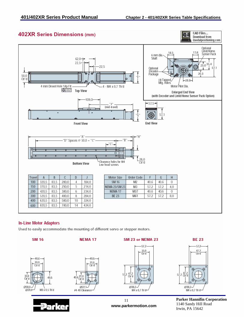
Dimensional Drawings
401/402XR Series Product Manual Chapter 2 - 401/402XR Series Table Specifications
11 www.parkermotion.com
Parker Hannifin Corporation 1140 Sandy Hill Road Irwin, PA 15642

401/402XR Series Product Manual Chapter 2 - 401/402XR Series Table Specifications
12 www.parkermotion.com
Parker Hannifin Corporation 1140 Sandy Hill Road Irwin, PA 15642
General Table Specifications
Precision Grade Standard Grade Common Characteristics 401XR 402XR 401XR 402XR Performance Bidirectional Repeatability (µm) 2 mm lead 5 or 10 mm lead
+/-1.3 +/-1.3
NA +/-1.3
+/-5 +/-12
NA +/-12
Duty Cycle 100% 100% 100% 100% Max Acceleration – m/sec2 (in/sec2) 20 (773) 20 (773) 20 (773) 20 (773) Rated Capacity Normal load – kgf (lbs)
50 (110)
100 (220)
50 (110)
100 (220)
Axial load – kgf (lbs) 2 mm lead 5 or 10 mm lead
5.5 (12.1) 15.5 (34.2)
NA
38 (84)
5.5 (12.1) 15.5 (34.2)
NA
38 (84) Motor Sizing Drive Screw Efficiency
80% 80% 80% 80%
Max Break-Away Torque Nm (in-oz) 0.03 (4.2) 0.086 (12.0) 0.03 (4.2) 0.086 (12.0) Max Running Torque – Nm (in-oz) 0.028 (4.0) 0.08 (11.3) 0.028 (4.0) 0.08 (11.3) Linear Bearing – Coefficient of Friction 0.01 0.01 0.01 0.01 Ballscrew Diameter – mm 2 mm lead 5 or 10 mm lead
6 8
NA 12
6 8
NA 12
Output Shaft Diameter – mm 5 6 5 6 Carriage Weight – kgf (lbs) 0.045 (0.1) 0.11 (0.25) 0.045 (0.1) 0.11 (0.25)
Input Inertia Positional Accuracy (µm) 10-3 kg-cm2
Max Screw Speed (Revs Per Second)
Unit Weight (kg)
401 402
Straightness & Flatness
Accuracy (µm) 401 402 401 402 401 402 Travel (mm)
P* S P* S 401 402 2 mm 10 mm 5 mm 10 mm 50 10 20 - - 20 - 0.6 - - - 70 - 1.0 -
100 10 20 10 20 20 20 0.9 - 12.0 - 70 70 1.2 2.3 150 12 20 12 20 20 20 1.1 - 15.0 - 70 70 1.3 2.6 200 16 30 16 30 25 25 - 4.7 20.0 - 70 70 1.5 2.8 300 18 40 18 40 25 25 - 5.2 - 25.0 70 70 1.7 3.2 400 - - 21 40 - 30 - - - 29.0 - 55 - 3.8 600 - - 25 50 - 30 - - - 39.0 - 30 - 4.8
*Accuracy stated is at 20oC utilizing slope correction factor provided.

401/402XR Series Product Manual Chapter 2 - 401/402XR Series Table Specifications
13 www.parkermotion.com
Parker Hannifin Corporation 1140 Sandy Hill Road Irwin, PA 15642
401-402XR Series Technical Data The useful life of a linear table at full catalog specifications is dependent on the forces acting upon it. These forces include both static components resulting from payload weight, and dynamic components due to acceleration/deceleration of the load. In multi-axes applications, the primary positioner at the bottom of the stack usually establishes the load limits for the combined axes. When determining load/life, it is critical to include the weight of all positioning elements that contribute to the load supported by the primary axis. The life/load charts are used to establish the table life relative to the applied loads.
Thrust Load
1000
10000
100000
1000000
10000000
100000000
1000000000
0 50 100 150 200 250 300 350 400
N
Life
(Km
)
401XR 2mm Lead
401XR 5mm Lead
402XR 5mm Lead
402XR 10mm Lead
Life with Compression Load
1000
10000
100000
1000000
10000000
100000000
1000000000
10000000000
0 100 200 300 400 500 600 700 800 900 1000
N
Life
(Km
)
401XR
402XR
Table Load Chart The “Table Load” chart is intended to provide a rough-cut evaluation “life/load” characteristics of the carriage support bearings. This curve is based on the applied load being centered on the carriage, normal to the carriage mounting surface.
Thrust Load Chart The “Thrust Load” chart illustrates table ballscrew life relative to the axial load.
401/402XR Series Product Manual Chapter 2 - 401/402XR Series Table Specifications
14 www.parkermotion.com
Parker Hannifin Corporation 1140 Sandy Hill Road Irwin, PA 15642
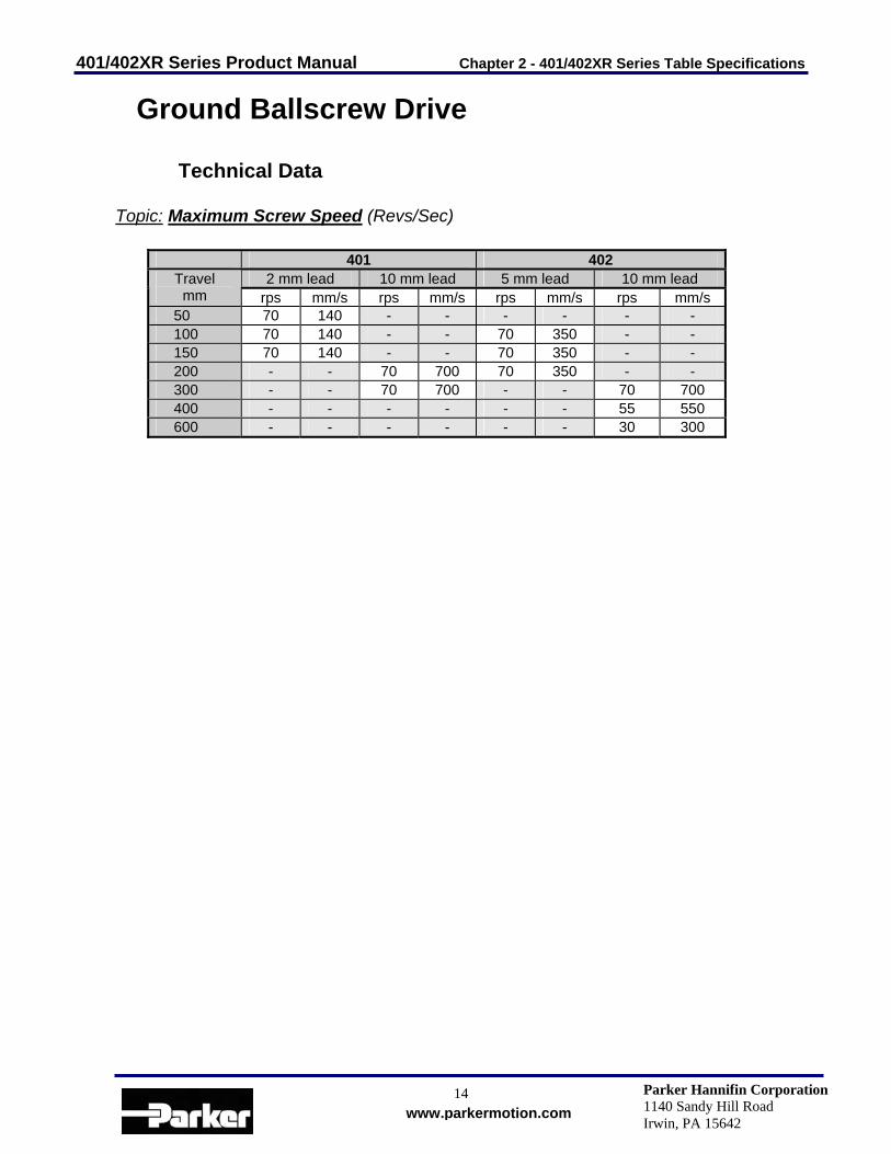
Ground Ballscrew Drive
Technical Data Topic: Maximum Screw Speed (Revs/Sec)
401 402 2 mm lead 10 mm lead 5 mm lead 10 mm lead Travel
mm rps mm/s rps mm/s rps mm/s rps mm/s 50 70 140 - - - - - - 100 70 140 - - 70 350 - - 150 70 140 - - 70 350 - - 200 - - 70 700 70 350 - - 300 - - 70 700 - - 70 700 400 - - - - - - 55 550 600 - - - - - - 30 300

401/402XR Series Product Manual Chapter 3 - Component Specifications
15 www.parkermotion.com
Parker Hannifin Corporation 1140 Sandy Hill Road Irwin, PA 15642
Chapter 3 - Component Specifications
Linear Encoders
Description Specification Input Power 5 VDC +/- 5% 150mA Output (incremental) Square wave differential line driver (EIA RS422) 2
channels A and B in quadrature (90) phase shift Reference (Z channel) – see below for additional information
Synchronized pulse, duration equal to one resolution bit. Repeatability of position is unidirectional moving toward non-motor end.
Positional Accuracy +/- 3 microns after linear slope correction Maximum Speed – see page 14 for additional information
1.0 micron resolution = 3.0 meters/sec 0.5 micron resolution = 1.5 meters/sec 0.1 micron resolution = 0.3 meters/sec
Z-Channel Position Reference
The Z channel is an output on the encoder. Many servo controllers support this input. The Z channel on the 401/402XR is located at mid travel. The Z channel is a unidirectional device. This means that the final homing direction must occur in one direction. The 401/402XR is set so that the final home direction is to be toward the non-motor end of the table. The repeatability of the Z channel is equal to +/- 2 resolution counts of the encoder (except for 0.1 micron scales which have a repeatability of +/-1 microns). Thus the repeatability of the “Z” channel equals:
Encoder Resolution Z Channel Repeatability 1 micron +/- 2 micron 0.5 micron +/- 1 micron 0.1 micron +/- 1 micron
NOTE: Home repeatability is also very dependent on controller input speed and homing algorithms. The above repeatability does not include possible controller tolerance. Additionally, to achieve the highest repeatability the final homing speed must be slow. Slower final speed usually results in higher repeatability. NOTE: The “Z” channel output is only one resolution count wide. Thus the on-time may be very brief. Due to this some controllers may have difficulty reading the signal. If you are experiencing the positioner not finding the “Z” channel during homing, try reducing final homing speed; also refer to your controller manual for frequency rates of the “Z” channel input.
401/402XR Series Product Manual Chapter 3 - Component Specifications
16 www.parkermotion.com
Parker Hannifin Corporation 1140 Sandy Hill Road Irwin, PA 15642
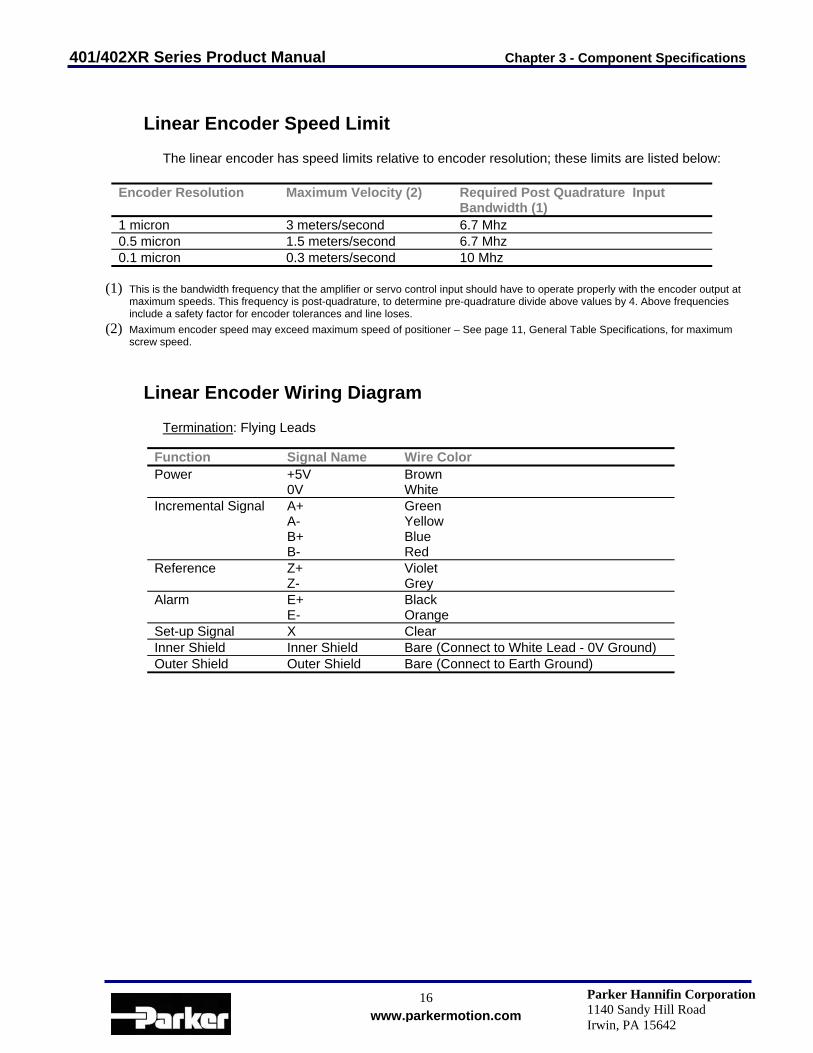
Linear Encoder Speed Limit
The linear encoder has speed limits relative to encoder resolution; these limits are listed below:
Encoder Resolution Maximum Velocity (2) Required Post Quadrature Input
Bandwidth (1) 1 micron 3 meters/second 6.7 Mhz 0.5 micron 1.5 meters/second 6.7 Mhz 0.1 micron 0.3 meters/second 10 Mhz
(1) This is the bandwidth frequency that the amplifier or servo control input should have to operate properly with the encoder output at maximum speeds. This frequency is post-quadrature, to determine pre-quadrature divide above values by 4. Above frequencies include a safety factor for encoder tolerances and line loses.
(2) Maximum encoder speed may exceed maximum speed of positioner – See page 11, General Table Specifications, for maximum screw speed.
Linear Encoder Wiring Diagram
Termination: Flying Leads Function Signal Name Wire Color Power +5V
0V Brown White
Incremental Signal A+ A- B+ B-
Green Yellow Blue Red
Reference Z+ Z-
Violet Grey
Alarm E+ E-
Black Orange
Set-up Signal X Clear Inner Shield Inner Shield Bare (Connect to White Lead - 0V Ground) Outer Shield Outer Shield Bare (Connect to Earth Ground)
401/402XR Series Product Manual Chapter 3 - Component Specifications
17 www.parkermotion.com
Parker Hannifin Corporation 1140 Sandy Hill Road Irwin, PA 15642
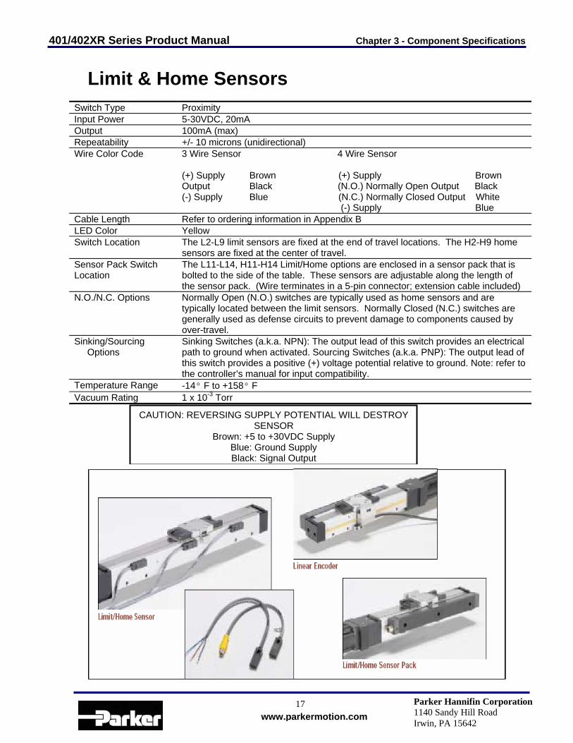
Limit & Home Sensors Switch Type Proximity Input Power 5-30VDC, 20mA Output 100mA (max) Repeatability +/- 10 microns (unidirectional) Wire Color Code 3 Wire Sensor 4 Wire Sensor
(+) Supply Brown (+) Supply Brown Output Black (N.O.) Normally Open Output Black (-) Supply Blue (N.C.) Normally Closed Output White (-) Supply Blue
Cable Length Refer to ordering information in Appendix B LED Color Yellow Switch Location The L2-L9 limit sensors are fixed at the end of travel locations. The H2-H9 home
sensors are fixed at the center of travel. Sensor Pack Switch Location
The L11-L14, H11-H14 Limit/Home options are enclosed in a sensor pack that is bolted to the side of the table. These sensors are adjustable along the length of the sensor pack. (Wire terminates in a 5-pin connector; extension cable included)
N.O./N.C. Options Normally Open (N.O.) switches are typically used as home sensors and are typically located between the limit sensors. Normally Closed (N.C.) switches are generally used as defense circuits to prevent damage to components caused by over-travel.
Sinking/Sourcing Options
Sinking Switches (a.k.a. NPN): The output lead of this switch provides an electrical path to ground when activated. Sourcing Switches (a.k.a. PNP): The output lead of this switch provides a positive (+) voltage potential relative to ground. Note: refer to the controller’s manual for input compatibility.
Temperature Range -14° F to +158° F Vacuum Rating 1 x 10⁻³ Torr
CAUTION: REVERSING SUPPLY POTENTIAL WILL DESTROY SENSOR
Brown: +5 to +30VDC Supply Blue: Ground Supply Black: Signal Output
401/402XR Series Product Manual Chapter 3 - Component Specifications
18 www.parkermotion.com
Parker Hannifin Corporation 1140 Sandy Hill Road Irwin, PA 15642
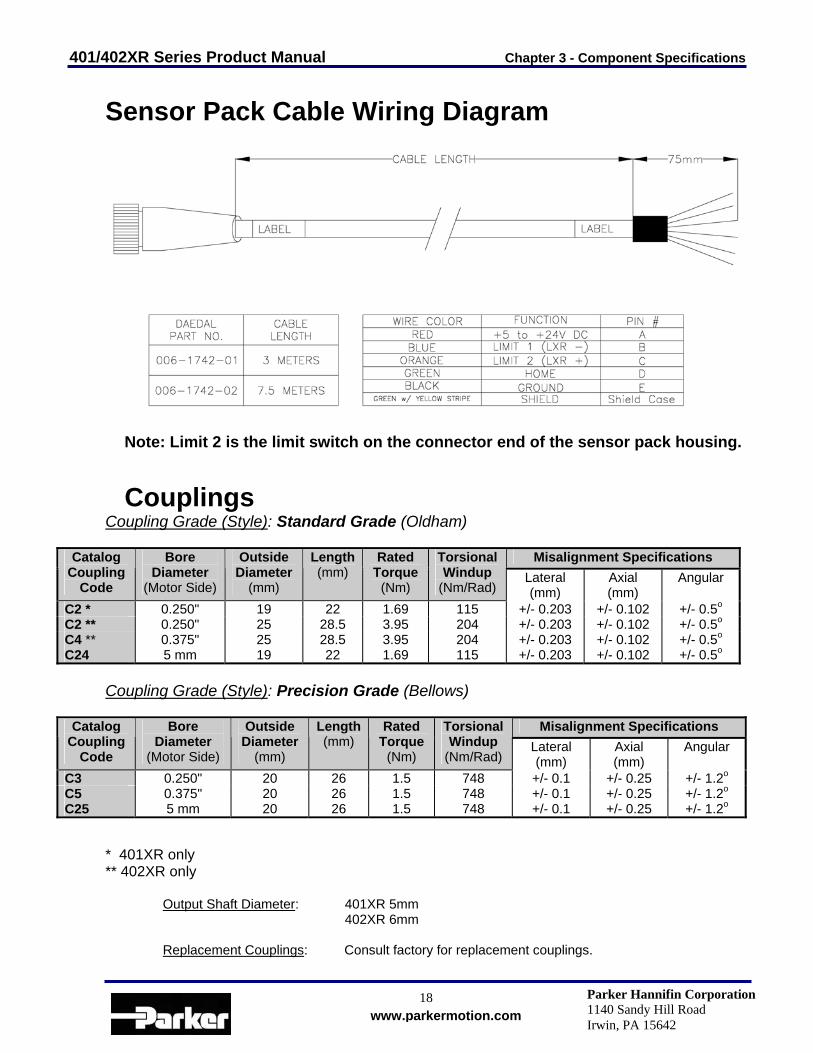
Sensor Pack Cable Wiring Diagram
Note: Limit 2 is the limit switch on the connector end of the sensor pack housing.
Couplings
Coupling Grade (Style): Standard Grade (Oldham)
Misalignment Specifications Catalog Coupling
Code
Bore Diameter
(Motor Side)
Outside Diameter
(mm)
Length (mm)
Rated Torque
(Nm)
Torsional Windup
(Nm/Rad) Lateral (mm)
Axial (mm)
Angular
C2 * 0.250" 19 22 1.69 115 +/- 0.203 +/- 0.102 +/- 0.5o C2 ** 0.250" 25 28.5 3.95 204 +/- 0.203 +/- 0.102 +/- 0.5o C4 ** 0.375" 25 28.5 3.95 204 +/- 0.203 +/- 0.102 +/- 0.5o C24 5 mm 19 22 1.69 115 +/- 0.203 +/- 0.102 +/- 0.5o
Coupling Grade (Style): Precision Grade (Bellows)
Misalignment Specifications Catalog Coupling
Code
Bore Diameter
(Motor Side)
Outside Diameter
(mm)
Length (mm)
Rated Torque
(Nm)
Torsional Windup
(Nm/Rad) Lateral (mm)
Axial (mm)
Angular
C3 0.250" 20 26 1.5 748 +/- 0.1 +/- 0.25 +/- 1.2o C5 0.375" 20 26 1.5 748 +/- 0.1 +/- 0.25 +/- 1.2o C25 5 mm 20 26 1.5 748 +/- 0.1 +/- 0.25 +/- 1.2o
* 401XR only ** 402XR only
Output Shaft Diameter: 401XR 5mm 402XR 6mm
Replacement Couplings: Consult factory for replacement couplings.

401/402XR Series Product Manual Chapter 4 - Base Mounting Procedures
19 www.parkermotion.com
Parker Hannifin Corporation 1140 Sandy Hill Road Irwin, PA 15642
Chapter 4 - Base Mounting Procedures
Mounting Surface Requirements Proper mounting of the 401/402XR is essential to optimize product performance. All specifications are based on the following conditions:
• The positioner must be bolted down along its entire length. • The positioner must be mounted to a flat, stable surface with a flatness error less than or equal to
0.013mm/300mm.
• Catalog specifications may deviate for positioners mounted to surfaces that do not meet the above conditions.
• If the surface does not met these specifications the surface can be shimmed to comply with these requirements.
• If mounting conditions require that the table base is overhung, table specifications will not be met over
that portion of the table. Additionally, in X-Y Systems the overhung portion of the Y-axis may not met specifications due to the additional error caused by deflection and non-support of the base. Contact Parker Hannifin Corporation for guidelines on specifications of overhang applications.
Base Mounting Methods
Base thru holes
The 401/402XR tables have counter bored holes in the base of the unit. See Dimensional Drawings, Chapter 2, for hole locations. See Internal Access Procedure, Chapter 6, to gain access to mounting holes.
Riser Blocks
Tools Required: Allen Key
Most of the motors used with the 401/402XR series have a taller profile than the positioner. Thus the unit cannot be mounted with the motor and table in the same plane. Riser blocks can be provided to space the table above a mounting surface.
• Locate sufficient amount of Riser Blocks for the required length of travel.
• Lay out Riser Blocks such that the entire length of the positioner is supported.
• Access interior of the positioner. See Internal Access Procedure Chapter 6.
• Mount Riser Blocks to the positioner using screws provided.
• Mount positioner to the work surface using counter-bored holes in the riser blocks.
• Reassemble positioner.

401/402XR Series Product Manual Chapter 5 - Component Mounting Procedures
20 www.parkermotion.com
Parker Hannifin Corporation 1140 Sandy Hill Road Irwin, PA 15642
Chapter 5 - Component Mounting Procedures
Center Drive Motor Mounting
Tools Required: Allen Key
• Slip coupling over drive shaft and tighten the screw on the drive shaft side of the coupling. Note: Do not use Loctite on coupling screws.
• Slide motor into motor adapter plate and into coupling. Select the appropriate hardware and tighten all
bolts.
• Tighten the coupling screw on the motor shaft side. Turn motor by the rear shaft to make sure carriage moves. Then hold carriage and rotate motor again by the rear shaft to make sure coupling won’t slip. If the motor does not have a rear shaft be certain that the coupling screws are tight. Note: Do not use Loctite on coupling screws.
Limit/Home Switch Mounting Procedure
Tools Required For Adjustment: Allen Key
Travel limit sensors signal the motor to stop whenever the table carriage is approaching the end of travel. These sensors are fixed at the end of table travel. The home sensor provides a fixed reference point which the carriage can be commanded to return repeatedly. This sensor is fixed at the center of travel.
• Identify limit/home sensors and mounting hardware per the configuration, which is appropriate to the
application. • Normally Closed, Current Sinking • Normally Open, Current Sinking • Normally Closed, Current Sourcing • Normally Open, Current Sourcing
• Attach the limit and home switches to side of unit using flat head screws, making sure they run parallel to
the side of the carriage.
• Attach sensor flag to side of carriage with button head screws.
• Run the carriage the full travel and make sure that the sensors do not interfere with the sensor flag.
• Refer to Wire Color Code in Chapter 3.
NOTE: When adjusting Sensor Pack switches, the screws may be turned a maximum of 1/4 turn. Any further loosening may result in the nut becoming disengaged. If this occurs the sensor pack will need to be disassembled so that the nut can be reattached.

401/402XR Series Product Manual Chapter 6 – Internal Access and Lubrication
21 www.parkermotion.com
Parker Hannifin Corporation 1140 Sandy Hill Road Irwin, PA 15642
Chapter 6 – Internal Access and Lubrication
Internal Access Procedure
Tools Required: Ball driver or Allen Key
Procedure: The following procedure outlines the steps required to access the mounting holes located inside the unit.
• Remove the strip seal clamps and carefully pull back strip seal. • CAUTION: Edges of strip seal are very sharp. Use caution while handling the strip seal. • If you are using a round ended ball driver you will be able to tighten/loosen the base mounting screws. • If you are using an Allen key you will need to remove the side covers. Remove the screws on the bottom
of the side cover and slide off the side. You will now be able to access the base mounting screws with the Allen key.
Square Rail Bearing Lubrication
The square rail bearings are lubricated for the life of the table. No further lubrication is required.
Ground Ballscrew Lubrication
The ballscrew is lubricated for the life of the table. No further lubrication is required.
401/402XR Series Product Manual Appendix A - Internal Protection
22 www.parkermotion.com
Parker Hannifin Corporation 1140 Sandy Hill Road Irwin, PA 15642
Appendix A - Internal Protection
The 404XR is protected from its environment via magnetically retained Protective Seals. Parker Hannifin Corporation has conducted testing to determine the degree to which the positioner is protected by using a British standard called an Ingress Protection Rating (IP Rating).
Definition
Reference: British standard EN 60529: 1992 This standard describes a system of classifying degrees of protection provided by enclosures of electrical equipment. Standardized test methods and the establishment of a two digit numeric rating verify the extent of protection provided against access to hazardous parts, against ingress of solid foreign objects, and against the ingress of water. First Number – The first number indicates protection of persons against access to dangerous parts and protection of internal equipment against the ingress of solid foreign objects.
1 - Protection against access to hazardous parts with the back of a hand, and protected against solid foreign objects of 50 mm diameter and larger.
2 - Protection of fingers against access to dangerous parts, and protection of equipment
against solid foreign objects of 12.5 mm diameter and larger.
3 - Protection against access to hazardous parts with a tool, and protection against solid foreign objects of 2.5 mm diameter and larger.
Second Number – The second number indicates protection of internal equipment against harmful ingress of water. 0 - No special protection provided. Note: Number Indicators above represent only a partial list of IP Rating specifications. Warnings (Points of Clarity)
• The specification applies to protection of particles, tools, parts of the body, etc., against access to
hazardous parts inside the enclosure. This does not cover external features such as switch pinch points, pinch points causes by the motion of the carriage, or cable carrier assemblies.
• The testing method as specified in the standard uses a solid steel rod of the appropriate diameter at a
specified force. The specification does not consider soft or pliable particles. Due to the design of the table and sealing method, a soft particle can compress due to the motion of the table, and reduce its cross-section. This can allow particles to enter the unit.
• In application, shavings or chips commonly created in a machining operation are a greater concern. If
any edge or dimension of the “chip” is under the appropriate diameter, it can wedge under and start to the lift the seals. This action will allow larger particles to do the same until failure is reached.
401/402XR Series Product Manual Appendix A - Internal Protection
23 www.parkermotion.com
Parker Hannifin Corporation 1140 Sandy Hill Road Irwin, PA 15642
Using the "IP Ship Kit"
All standard configurations will pass IP20 specifications with the following exception:
All standard configurations can be configured to pass IP30 specifications by utilizing the “IP ship kit” supplied with each unit as follows:
• Using the supplied aluminum foil disks, cover all counter-bored base mounting holes that are not covered by your mounting surface. The disks should be installed from the outside of the unit. Depending on the travel length, some disks will not be used. Use the 0.75 inch diameter disk to cover the large hole on the drive end of the unit.
• Using the supplied aluminum foil disks, plug any exposed holes on side covers of the unit. The number
of holes on the side covers will vary with the options ordered.

401/402XR Series Product Manual Appendix B-Accessories & Spare Parts
24 www.parkermotion.com
Parker Hannifin Corporation 1140 Sandy Hill Road Irwin, PA 15642
Appendix B - Accessories & Spare Parts

401/402XR Series Product Manual Appendix B-Accessories & Spare Parts
25 www.parkermotion.com
Parker Hannifin Corporation 1140 Sandy Hill Road Irwin, PA 15642
Mounting Bracket Configuration
X – Y Y Axis401XR 50mm 401XR > 50mm 402XR
401XR 002-2126-01 002-2065-01 N/AX Axis402XR 002-2130-01 002-2066-01 002-2066-01
X – YCartesian Y Axis
401XR 50mm 401XR > 50mm 402XR401XR 002-2123-01 002-2068-01 N/AX Axis402XR 002-2069-01 002-2069-01 002-2069-01
X – Z Z Axis401XR 50mm 401XR > 50mm 402XR
401XR N/A 002-2068-01 N/AX Axis402XR N/A 002-2069-01 002-2069-01
X – Z SideMount Z Axis
401XR 50mm 401XR > 50mm 402XR401XR 002-2123-01 002-2068-01 N/AX Axis402XR 002-2125-01 002-2069-01 002-2069-01
Riser Plates401XR 002-2063-01402XR 002-2064-01
Additional Mounting PlatesTo 404XR 100-9193-01To 406XR 100-9194-01

401/402XR Series Product Manual Appendix B-Accessories & Spare Parts
26 www.parkermotion.com
Parker Hannifin Corporation 1140 Sandy Hill Road Irwin, PA 15642
Mounting Bracket Dimensions
41.0
115.0
10.0
002-2126-01
15.0
90.0
10.0
Ø4.2
Ø7.0
002-2064-01002-2063-01
15.0 17.0
65.0
Ø7.0
Ø4.2
**002-2125-01
**002-2123-01
002-2066-01
**Part Number Includes 002-2129-01
100-9194-01 100-9193-01
002-2069-01
9.565.0
89.8
9.5
78.8
Ø4.0
10.0
95.0
16 x Ø3.3
150.0
18 x Ø5.04 x Ø6.6
10.0
127.0
Ø4.0
112.0
16 x Ø5.0
16 x Ø3.3
Ø4.0
8.7
48.0
48.0
002-2065-01
002-2068-01
9.5
71.0
48.0
63.8Ø4.5
Ø4.0
9.5
**002-2130-01
65.0
57.5
8.0
Ø2.0
8.7
16 x M4-0.7 Tap Thru
8 x M4-0.7 Thd Thru
4 x Ø4.5Drill Thru
8 x M4-0.7Tap Thru
Ø4.0
6 x M4-0.7 Tap Thru
2 x Ø4.5 Drill Thru and Ø8.0
C'Bore x 4.5 Deep
4 x M4-0.7 Tap Thru