Embed Size (px)
Citation preview

INFORMATION SYSTEMS @ XINFORMATION SYSTEMS @ X
INFO425: Systems DesignINFO425: Systems Design
Chapter 10Chapter 10
Traditional Approach to DesignTraditional Approach to Design
INFO425: Systems DesignINFO425: Systems Design
INFORMATION SYSTEMS @ XINFORMATION SYSTEMS @ X
Learning ObjectivesLearning Objectives
Describe the steps involved in the traditional approach Describe the steps involved in the traditional approach to designing the application architectureto designing the application architecture
Develop a system flowchartDevelop a system flowchart Develop a structure chart using transaction analysis and Develop a structure chart using transaction analysis and
transform analysistransform analysis Write pseudocode for structured modulesWrite pseudocode for structured modules Explain how to use three-layer design with the Explain how to use three-layer design with the
traditional approachtraditional approach
INFO425: Systems DesignINFO425: Systems Design
INFORMATION SYSTEMS @ XINFORMATION SYSTEMS @ X
OverviewOverview
Traditional approach to designing softwareTraditional approach to designing software Overview of structured models, model development process, Overview of structured models, model development process,
related terminologyrelated terminology How data flow diagrams are annotated with automation How data flow diagrams are annotated with automation
boundary informationboundary information How analysis phase models are transformed into design How analysis phase models are transformed into design
models using system flowcharts, structure charts, and models using system flowcharts, structure charts, and module pseudocodemodule pseudocode
Integration into other design phase activitiesIntegration into other design phase activities Applying approach to a three-layer architectureApplying approach to a three-layer architecture
INFO425: Systems DesignINFO425: Systems Design
INFORMATION SYSTEMS @ XINFORMATION SYSTEMS @ X
The Structured Approach to Designing The Structured Approach to Designing the Application Architecturethe Application Architecture
Application software programsApplication software programs Designed in conjunction with database and user interfaceDesigned in conjunction with database and user interface Hierarchy of modulesHierarchy of modules
Design internal logic of individual modulesDesign internal logic of individual modules Top-down approachTop-down approach
DFDs with automation boundariesDFDs with automation boundaries System flowcharts, structure charts, pseudocodeSystem flowcharts, structure charts, pseudocode
INFO425: Systems DesignINFO425: Systems Design
INFORMATION SYSTEMS @ XINFORMATION SYSTEMS @ X
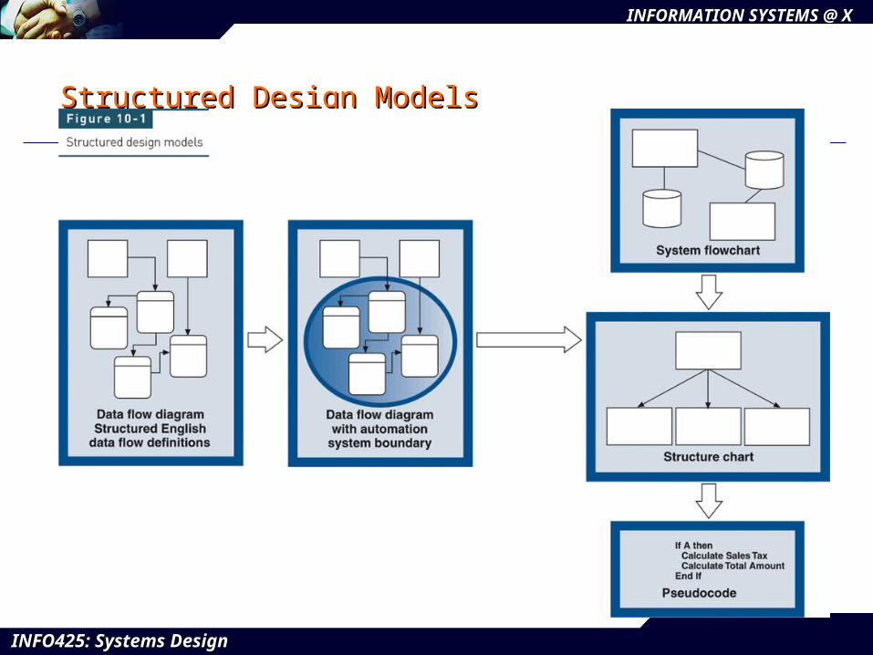
Structured Design ModelsStructured Design Models
INFO425: Systems DesignINFO425: Systems Design
INFORMATION SYSTEMS @ XINFORMATION SYSTEMS @ X
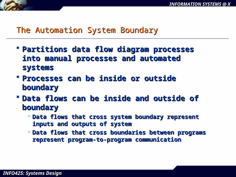
The Automation System BoundaryThe Automation System Boundary
Partitions data flow diagram processes into Partitions data flow diagram processes into manual processes and automated systemsmanual processes and automated systems
Processes can be inside or outside boundaryProcesses can be inside or outside boundary Data flows can be inside and outside of boundaryData flows can be inside and outside of boundary
Data flows that cross system boundary represent inputs and Data flows that cross system boundary represent inputs and outputs of systemoutputs of system
Data flows that cross boundaries between programs Data flows that cross boundaries between programs represent program-to-program communication represent program-to-program communication
INFO425: Systems DesignINFO425: Systems Design
INFORMATION SYSTEMS @ XINFORMATION SYSTEMS @ X
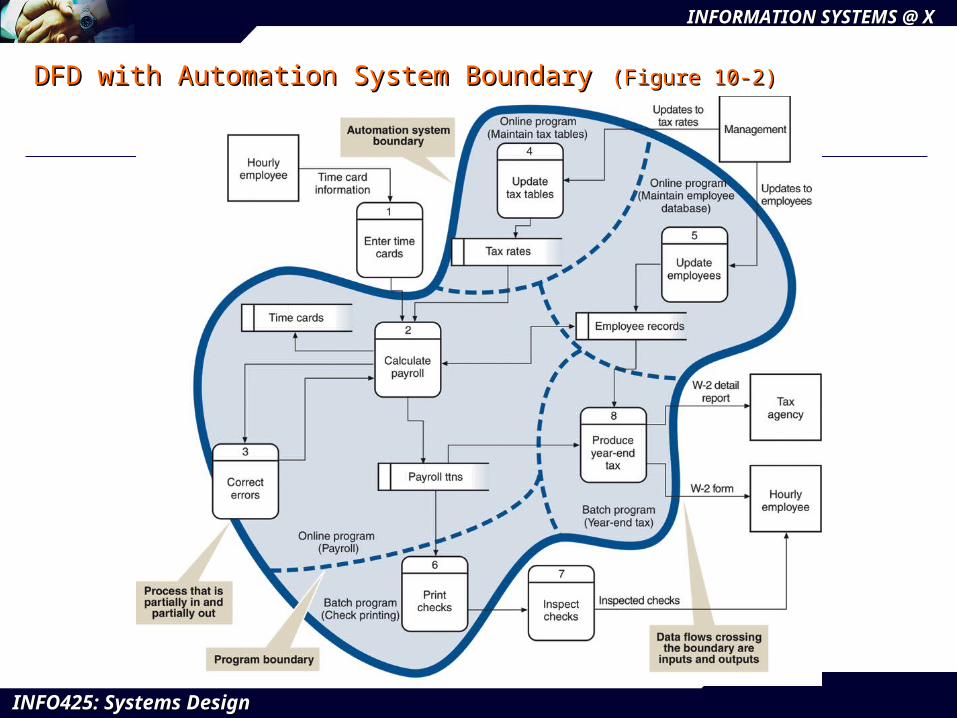
DFD with Automation System BoundaryDFD with Automation System Boundary (Figure 10-2)(Figure 10-2)
INFO425: Systems DesignINFO425: Systems Design
INFORMATION SYSTEMS @ XINFORMATION SYSTEMS @ X
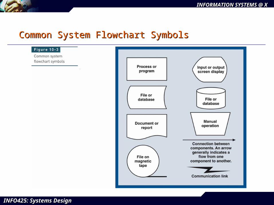
The System FlowchartThe System Flowchart
Representation of various computer programs, Representation of various computer programs, files, databases, and associated manual processes files, databases, and associated manual processes that make up complete systemthat make up complete system
Frequently constructed during analysis activitiesFrequently constructed during analysis activities Graphically describes organization of subsystems Graphically describes organization of subsystems
into automated and manual componentsinto automated and manual components Can show type of transaction processing systemCan show type of transaction processing system
BatchBatch Real-timeReal-time
INFO425: Systems DesignINFO425: Systems Design
INFORMATION SYSTEMS @ XINFORMATION SYSTEMS @ X
Common System Flowchart SymbolsCommon System Flowchart Symbols
INFO425: Systems DesignINFO425: Systems Design
INFORMATION SYSTEMS @ XINFORMATION SYSTEMS @ X
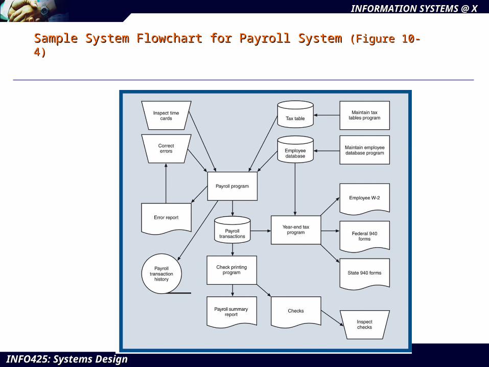
Sample System Flowchart for Payroll System Sample System Flowchart for Payroll System (Figure 10-4)(Figure 10-4)
INFO425: Systems DesignINFO425: Systems Design
INFORMATION SYSTEMS @ XINFORMATION SYSTEMS @ X
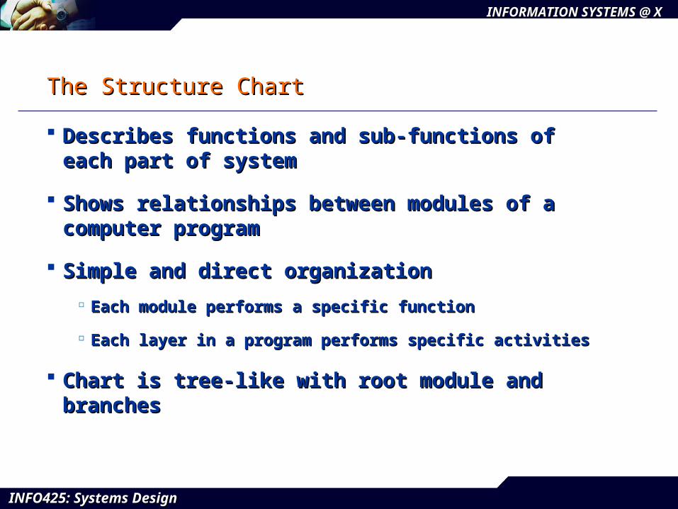
The Structure ChartThe Structure Chart
Describes functions and sub-functions of each Describes functions and sub-functions of each part of systempart of system
Shows relationships between modules of a Shows relationships between modules of a computer programcomputer program
Simple and direct organization Simple and direct organization
Each module performs a specific functionEach module performs a specific function
Each layer in a program performs specific activitiesEach layer in a program performs specific activities
Chart is tree-like with root module and branchesChart is tree-like with root module and branches
INFO425: Systems DesignINFO425: Systems Design
INFORMATION SYSTEMS @ XINFORMATION SYSTEMS @ X
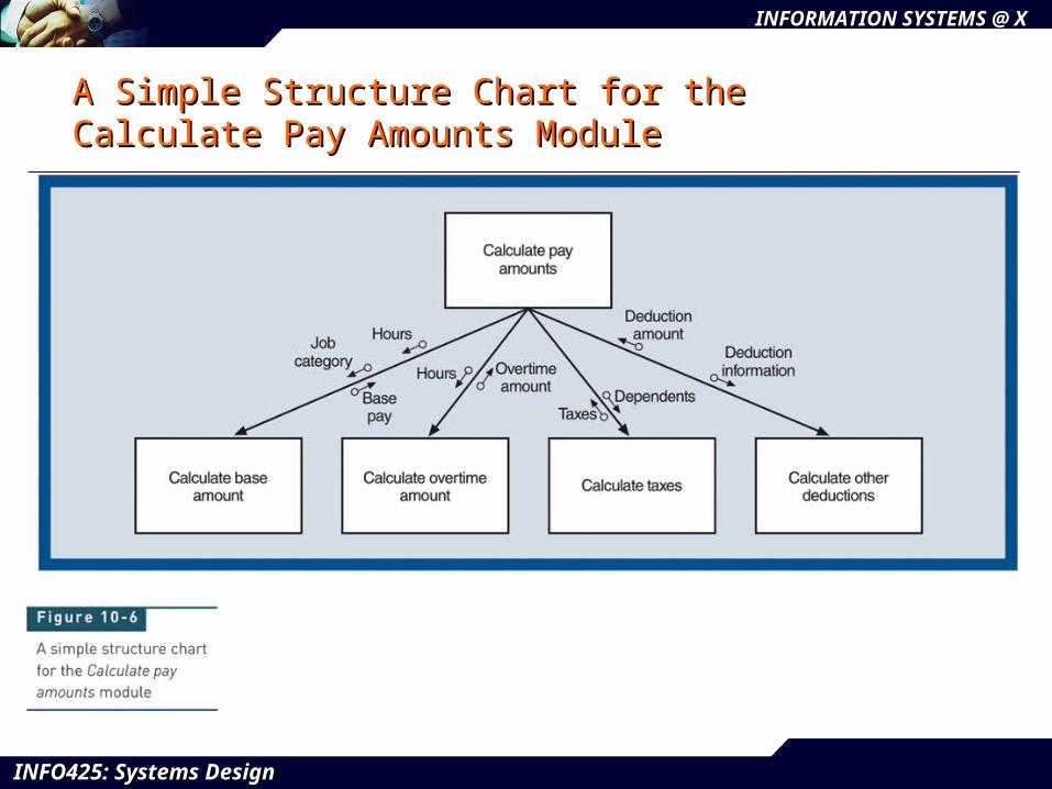
A Simple Structure Chart for the A Simple Structure Chart for the Calculate Pay Amounts ModuleCalculate Pay Amounts Module
INFO425: Systems DesignINFO425: Systems Design
INFORMATION SYSTEMS @ XINFORMATION SYSTEMS @ X
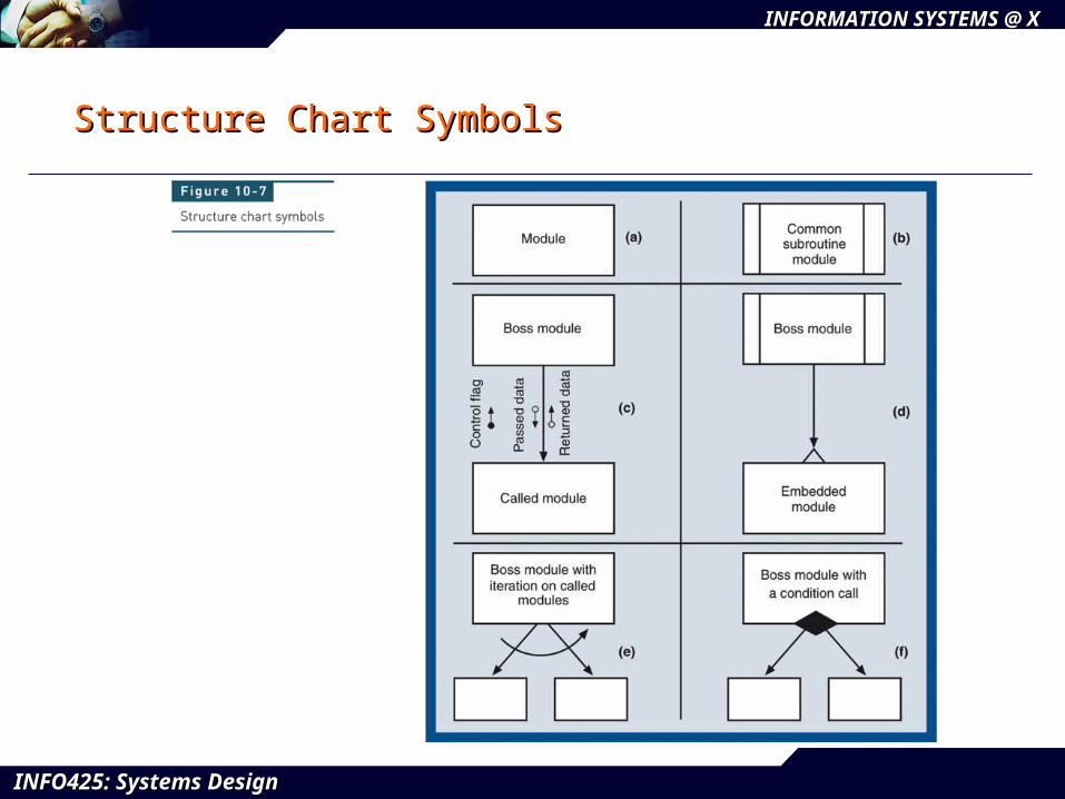
Structure Chart SymbolsStructure Chart Symbols
INFO425: Systems DesignINFO425: Systems Design
INFORMATION SYSTEMS @ XINFORMATION SYSTEMS @ X
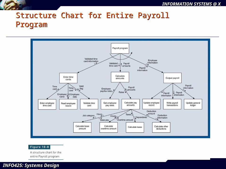
Structure Chart for Entire Payroll ProgramStructure Chart for Entire Payroll Program
INFO425: Systems DesignINFO425: Systems Design
INFORMATION SYSTEMS @ XINFORMATION SYSTEMS @ X
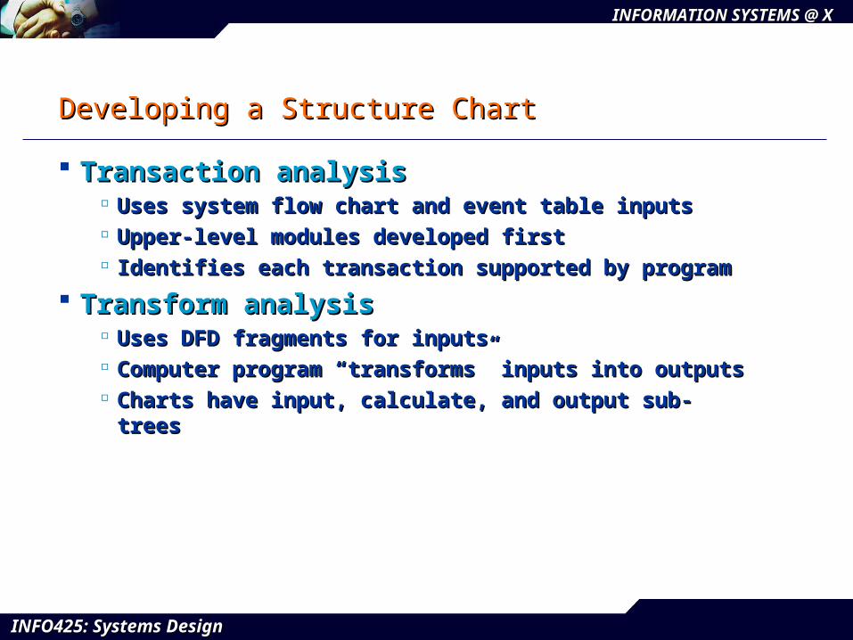
Developing a Structure ChartDeveloping a Structure Chart
Transaction analysisTransaction analysis Uses system flow chart and event table inputsUses system flow chart and event table inputs Upper-level modules developed firstUpper-level modules developed first Identifies each transaction supported by programIdentifies each transaction supported by program
Transform analysisTransform analysis Uses DFD fragments for inputsUses DFD fragments for inputs Computer program “transforms” inputs into outputsComputer program “transforms” inputs into outputs Charts have input, calculate, and output sub-treesCharts have input, calculate, and output sub-trees
INFO425: Systems DesignINFO425: Systems Design
INFORMATION SYSTEMS @ XINFORMATION SYSTEMS @ X
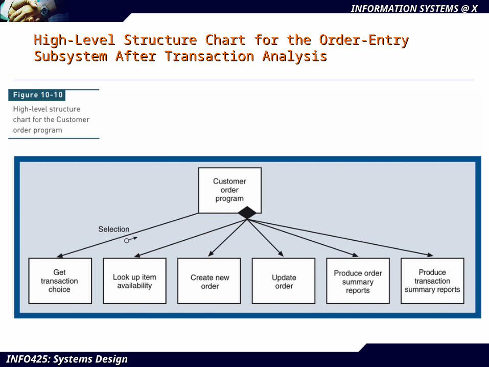
High-Level Structure Chart for the Order-Entry High-Level Structure Chart for the Order-Entry Subsystem After Transaction AnalysisSubsystem After Transaction Analysis
INFO425: Systems DesignINFO425: Systems Design
INFORMATION SYSTEMS @ XINFORMATION SYSTEMS @ X
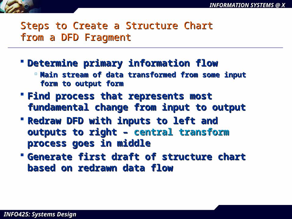
Steps to Create a Structure Chart Steps to Create a Structure Chart from a DFD Fragmentfrom a DFD Fragment
Determine primary information flowDetermine primary information flow Main stream of data transformed from some input form to Main stream of data transformed from some input form to
output formoutput form
Find process that represents most fundamental Find process that represents most fundamental change from input to outputchange from input to output
Redraw DFD with inputs to left and outputs to right Redraw DFD with inputs to left and outputs to right – – central transformcentral transform process goes in middle process goes in middle
Generate first draft of structure chart based on Generate first draft of structure chart based on redrawn data flowredrawn data flow
INFO425: Systems DesignINFO425: Systems Design
INFORMATION SYSTEMS @ XINFORMATION SYSTEMS @ X
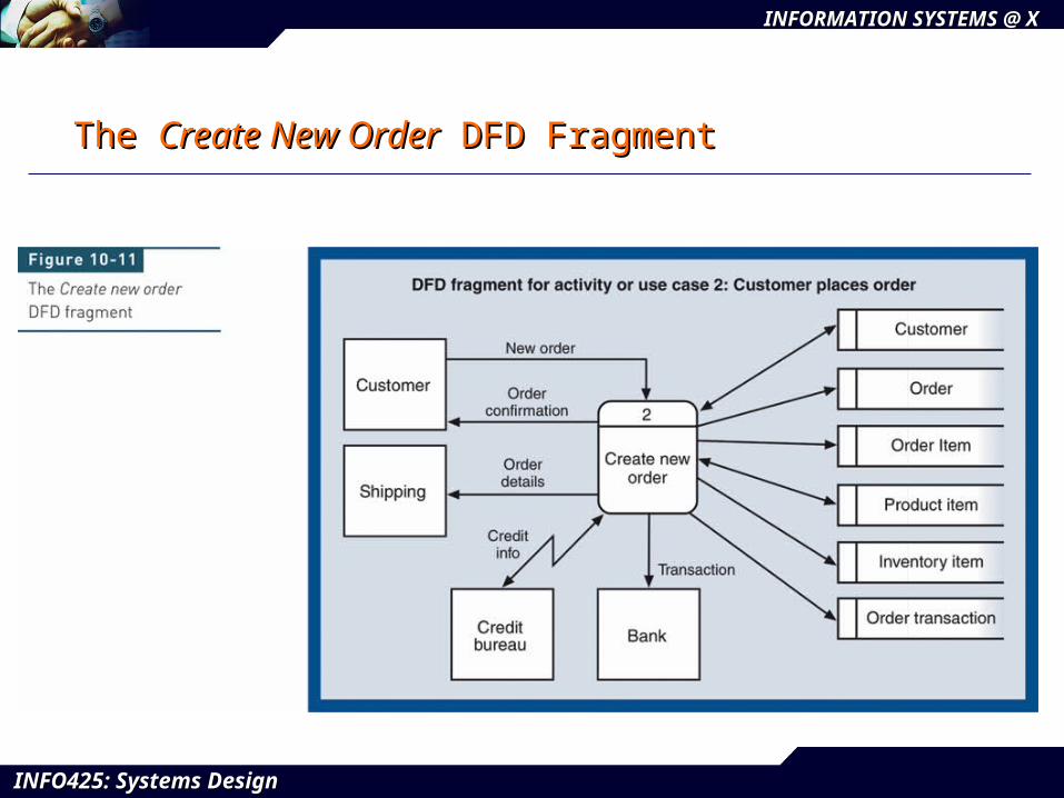
The The Create New OrderCreate New Order DFD Fragment DFD Fragment
INFO425: Systems DesignINFO425: Systems Design
INFORMATION SYSTEMS @ XINFORMATION SYSTEMS @ X
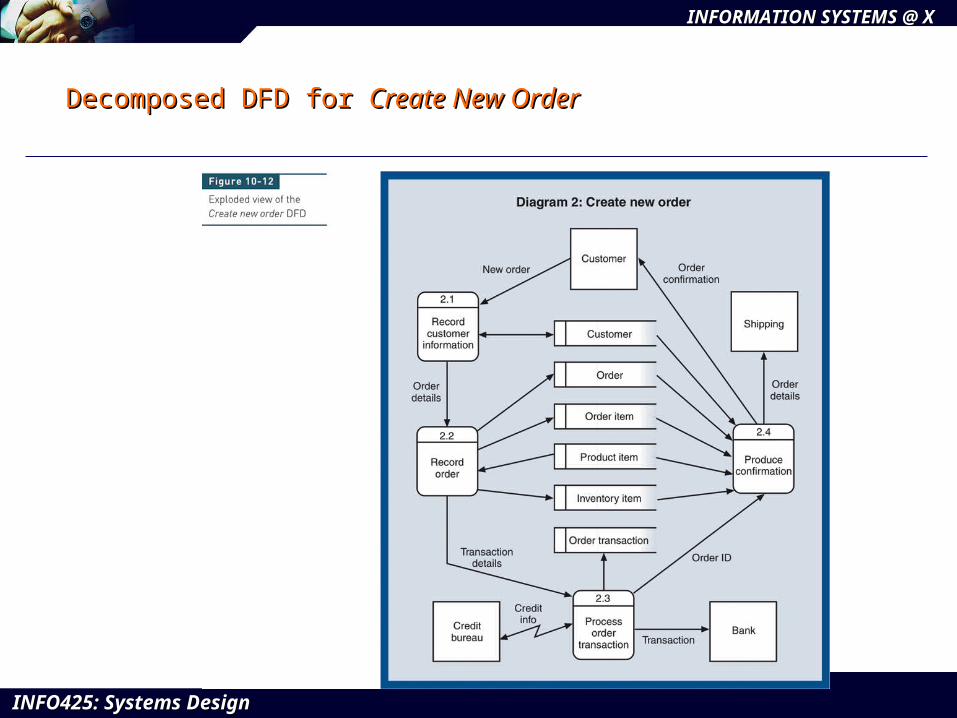
Decomposed DFD for Decomposed DFD for Create New OrderCreate New Order
INFO425: Systems DesignINFO425: Systems Design
INFORMATION SYSTEMS @ XINFORMATION SYSTEMS @ X
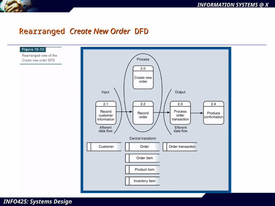
Rearranged Rearranged Create New OrderCreate New Order DFD DFD
INFO425: Systems DesignINFO425: Systems Design
INFORMATION SYSTEMS @ XINFORMATION SYSTEMS @ X
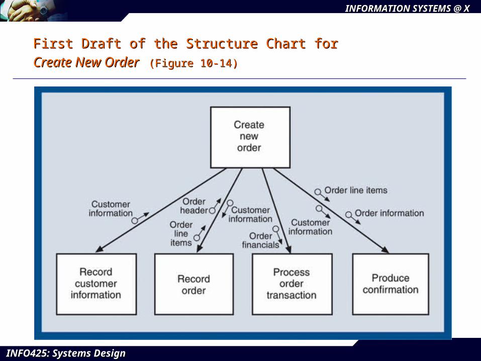
First Draft of the Structure Chart for First Draft of the Structure Chart for Create New OrderCreate New Order (Figure 10-14)(Figure 10-14)
INFO425: Systems DesignINFO425: Systems Design
INFORMATION SYSTEMS @ XINFORMATION SYSTEMS @ X
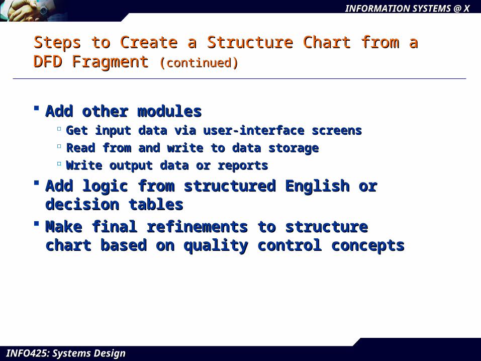
Steps to Create a Structure Chart from a DFD Steps to Create a Structure Chart from a DFD Fragment Fragment ((continuedcontinued))
Add other modules Add other modules Get input data via user-interface screensGet input data via user-interface screens Read from and write to data storageRead from and write to data storage Write output data or reports Write output data or reports
Add logic from structured English or decision Add logic from structured English or decision tablestables
Make final refinements to structure chart based on Make final refinements to structure chart based on quality control conceptsquality control concepts
INFO425: Systems DesignINFO425: Systems Design
INFORMATION SYSTEMS @ XINFORMATION SYSTEMS @ X
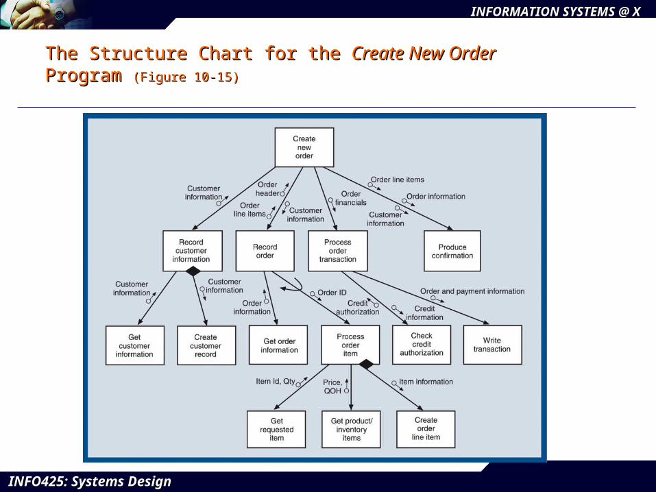
The Structure Chart for the The Structure Chart for the Create New OrderCreate New Order Program Program (Figure 10-15)(Figure 10-15)
INFO425: Systems DesignINFO425: Systems Design
INFORMATION SYSTEMS @ XINFORMATION SYSTEMS @ X
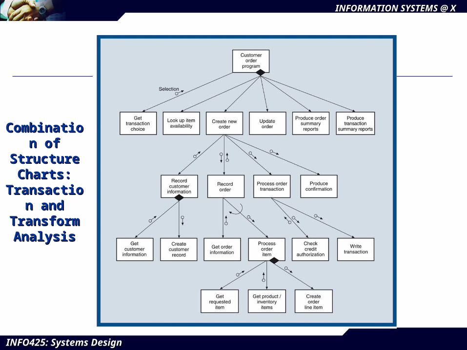
Combination Combination of Structure of Structure
Charts: Charts: Transaction Transaction
and and Transform Transform AnalysisAnalysis
INFO425: Systems DesignINFO425: Systems Design
INFORMATION SYSTEMS @ XINFORMATION SYSTEMS @ X
Evaluating the Quality of a Structure ChartEvaluating the Quality of a Structure Chart
Module coupling Module coupling Measure of how module is connected to other modules in Measure of how module is connected to other modules in
programprogram Goal is to be loosely coupled (independent)Goal is to be loosely coupled (independent)
Module cohesionModule cohesion Measure of internal strength of moduleMeasure of internal strength of module Module performs one defined taskModule performs one defined task Goal is to be highly cohesiveGoal is to be highly cohesive
INFO425: Systems DesignINFO425: Systems Design
INFORMATION SYSTEMS @ XINFORMATION SYSTEMS @ X
Module Algorithm DesignModule Algorithm Design——PseudocodePseudocode
Describes internal logic of software modulesDescribes internal logic of software modules Variation of structured English that is closer to Variation of structured English that is closer to
programming codeprogramming code Syntax should mirror development languageSyntax should mirror development language Three types of control statements used in Three types of control statements used in
structured programmingstructured programming SequenceSequence –– sequence of executable statements sequence of executable statements Decision Decision –– if-then-else logic if-then-else logic Iteration Iteration –– do-until or do-while do-until or do-while
INFO425: Systems DesignINFO425: Systems Design
INFORMATION SYSTEMS @ XINFORMATION SYSTEMS @ X
Integrating Structured Application Design with Integrating Structured Application Design with Other Design TasksOther Design Tasks
Structure chart must be modified or enhanced to Structure chart must be modified or enhanced to integrate design of integrate design of user interfaceuser interface and and databasedatabase
Are additional Are additional modulesmodules needed? needed? Does Does pseudocodepseudocode in modules need modification? in modules need modification? Are additional Are additional data couplesdata couples needed to pass data? needed to pass data?
Structure charts and system flowcharts must Structure charts and system flowcharts must correspond to planned correspond to planned network architecturenetwork architecture
Required protocols, capacity, and securityRequired protocols, capacity, and security
INFO425: Systems DesignINFO425: Systems Design
INFORMATION SYSTEMS @ XINFORMATION SYSTEMS @ X
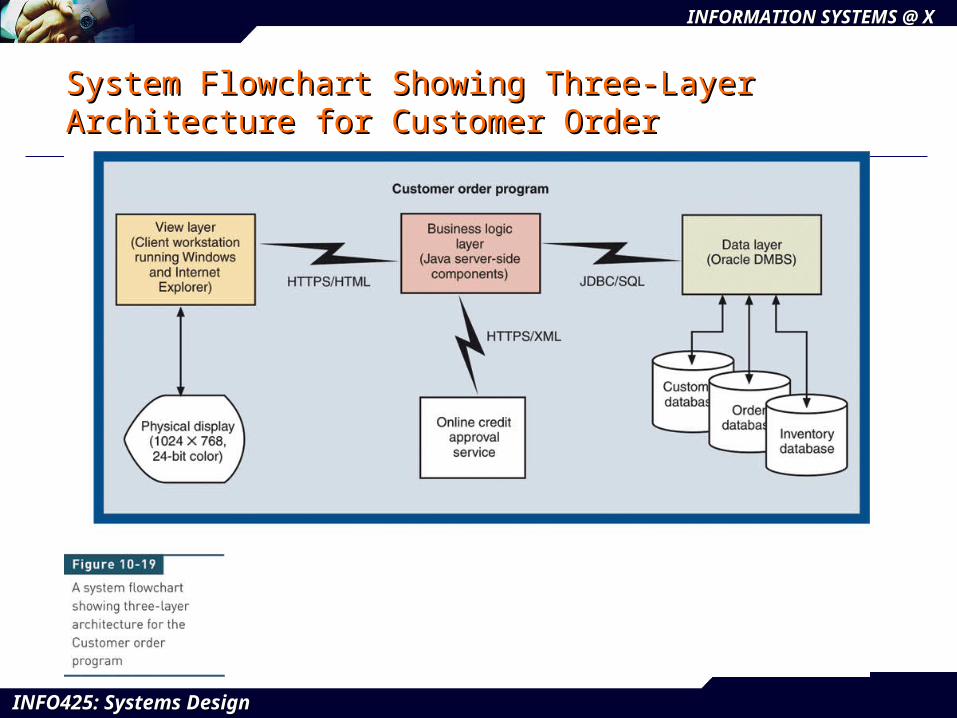
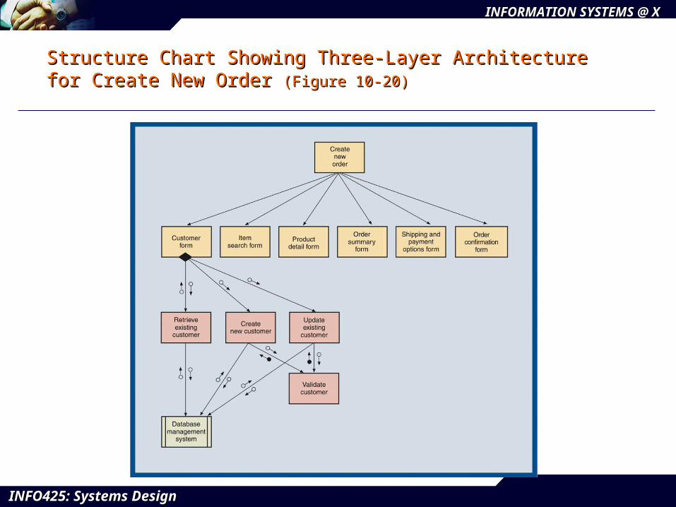
Three-Layer DesignThree-Layer Design
Three-layer architectureThree-layer architecture
View layer, business logic layer, and data layerView layer, business logic layer, and data layer
Structure charts and system flowcharts describe Structure charts and system flowcharts describe design decisions and software structuring design decisions and software structuring
Employs multiple programs for user interface, Employs multiple programs for user interface, business logic, and data access modulesbusiness logic, and data access modules
Modules in different layers communicate over real-Modules in different layers communicate over real-time links using well-defined protocolstime links using well-defined protocols
INFO425: Systems DesignINFO425: Systems Design
INFORMATION SYSTEMS @ XINFORMATION SYSTEMS @ X
System Flowchart Showing Three-Layer System Flowchart Showing Three-Layer Architecture for Customer OrderArchitecture for Customer Order
INFO425: Systems DesignINFO425: Systems Design
INFORMATION SYSTEMS @ XINFORMATION SYSTEMS @ X
Structure Chart Showing Three-Layer Architecture for Structure Chart Showing Three-Layer Architecture for Create New Order Create New Order (Figure 10-20)(Figure 10-20)