Embed Size (px)
Citation preview
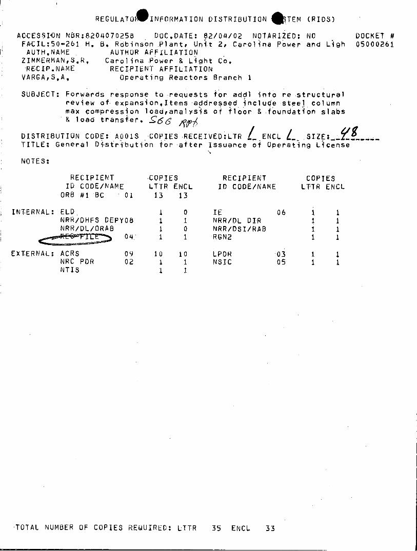
REGULATU INFORMATION DISTRIBUTION *TEM (RIDS)
ACOCESSIAON NBR:8204070258 DOC,DATE: 82/04/02 NOTARIZED: NO DOCKET # FATCIL:50-261 H, 8, Robinson Plant, Unit 2, Carolina Power and Ligh 05000261 AUTH.NAME AUTHOR AFFILIATION ZIMMERMANS,R, Carolina Power & Light Co, RECIP.NAME RECIPIENT AFFILIATION VARGASA, Operating Reactors Branch 1
SUBJECT: Forwards response to requests for addl into re structural review of expansionItems addressed include steel column max compression loadranalysis of floor &-foundation slabs & load transfer. -§g 66 ,
DISTRIBUTION CODE: A001S COPIES RECEIVED:LTR I ENCL SIZE TITLE: General Distribution for after issuance of Operating License
NOTES:
RECIPIENT COPIES RECIPIENT COPIES ID CODE/NAME LTTR ENCL ID CODE/NAME LTTR ENCL
OR6 #1 BC 01 13 13
INTERNAL: ELD 1 0 IE 06 1 1 NRR/DHFS DEPYO8 1 1 NRR/DL DIR 1 1 NRR/DL/ORAB 1 0 NRR/DSI/RAB 1 1
0~4. 1 1 RGN2 1
EXTERNAL: ACRS 09 10 10 LPDR 03 1 1 NRC PDR 02 1 1 NSIC 05 1 1 NTIS 1 1
'TOTAL NUMBER OF COPIES REQUIRED: LTTR 35 ENCL 33
CP&L Carolina Power & Light Company
APR 02 1982
Office of Nuclear Reactor Regulation ATTN: Mr. Steven A. Varga, Chief
Operating Reactors Branch No. 1 United States Nuclear Regulatory Commission Washington, D.C. 20555
H. B. ROBINSON STEAM ELECTRIC PLANT, UNIT NO. 2 DOCKET NO. 50-261 LICENSE NO. DPR-23
REQUEST FOR ADDITIONAL INFORMATION CONCERNING SPENT FUEL POOL EXPANSION
Dear Mr. Varga: p%
SUMMARY
Over the past several weeks Carolina Power & Light Com ( & has received several questions regarding the structural review of the . B. Robinson Steam Electric Plant, Unit No. 2 (HBR2) spent fuel pool expansion submittals. This letter documents those questions and provides CP&L's responses (see enclosures).
Should you have further questions regarding this information, please contact a member of our staff.
Yours very truly,
S. immerman Manager
Licensing & Permits
DCS/lr (n-5) Enclosures
cc: Mr. J. P. O'Reilly (NRC-RII) Mr. W. J. Ross (NRC)
e20407028 PDR A70OCX 080002 P 3DC~000o261
PDR
411 Fayetteville Street c P. 0. Box 1551 * Raleigh, N. C. 27602

ENCLOSURE A
H. B. ROBINSON STEAM ELECTRIC PLANT RESPONSE TO NRC INFORMATION REQUEST
1. NRC Comment
For the steel column design, the 33 1/3% increase in allowable stresses is not permitted when loads are combined with the operating basis earthquake (OBE). See NRC position for "review and acceptance of spent fuel storage and handling applications".
CP&L Comment
Standard Review Plan, Section 3.8.4, 11.5 states that the 33 1/3% increase is not permitted when combined with the OBE load. Calculations have been revised accordingly. There has been no impact on the design of the steel column.
See Attachment 1 for revised page 4-5b of the spent fuel pool submittal.
2. NRC Question
What is the maximum load in the column?
CP&L Response
The maximum compressive load is 293 kips for DBE load combination and 210 kips for OBE load combination.
3. NRC Question
Is the steel column always in compression?
CP&L Response
Yes
4. NRC Question
What is the ductility ratio (D.R.) for a fuel rack drop and a fuel assembly drop onto the spent fuel pool liner?
CP&L Response
For the fuel rack drop, D.R. = 6.2 where D.R. = plastic deformation elastic deformation

NRC acceptance criteria is for D.R. less than 10. This part of the analysis was performed by Ebasco.
For the fuel assembly drop, performed by Westinghouse, the term ductility ratio is not used. Instead of ductility ratio, Westinghouse makes a comparison of the compressive stress resulting from the impact force of a fuel assembly drop onto the pool liner and the allowable stress of the liner. From this comparison a margin of safety of six (6) was calculated.
5. NRC Question
Is SA-240 stainless steel material being used for the spent fuel storage racks?
CP&L Response
The following types of stainless steel materials are being used in the spent fuel racks:
SA 240 SA 312 SA 479 Type 304
6. NRC Question
How is the wrapper installed in the cells? Is it vented?
CP&L Response
As stated in Section 2 of CP&L's license amendment submittal dated December 1, 1980, the wrapper is attached to the outside of the cell by spot welding along the entire length of the wrapper. The wrapper covers the Boraflex material, and also provides for venting of the Boraflex to the pool environment.
7. NRC Question
The license amendment request states that the maximum seismic deflection at the top of the rack is 0.3".
a) What happens to adjacent racks - will they touch? b) Was the 0.3" deflection calculated at the maximum coefficient of
friction?
CP&L Response
The combination of sliding displacment at 1A = 0.2 with structural deflection at," = 0.8 was used to obtain the maximum deflection at the top of one rack. This is then combined by the square root sum of squares (SRSS) method with the structural deflection of a fixed, adjacent rack to

obtain the maximum rack-to-rack gap reduction (less than 0.3") for SSE seismic conditions. Conservatively adding the displacement due to a simultaneous thermal accident, the maximum gap reduction of 0.455" is less than the minimum as-installed gap of 1.00", therefore the rack will not touch.
8. NRC Comment
The NRC does not have structural drawings showing plans and elevations of the spent fuel pool slab and mat.
CP&L Response
One copy of the following Ebasco drawings was given to NRC on January 14, 1982:
G-190420 Fuel Handling Building Plan & Details, Ele. 226.0, Masonry G-190423 Fuel Handling Building Sections & Elevations - Masonry, Sheet 1 G-190424 Fuel Handling Building Sections & Elevations - Masonry, Sheet 2 G-190426 Fuel Handling Building Spent Fuel Pit - Reinforcement, Sheet 1 G-190427 Fuel Handling Building Spent Fuel Pit - Reinforcement, Sheet 2
9. NRC Question
Have the floor and foundation slabs been analyzed for the new column loads? Providecomputations.
CP&L Response
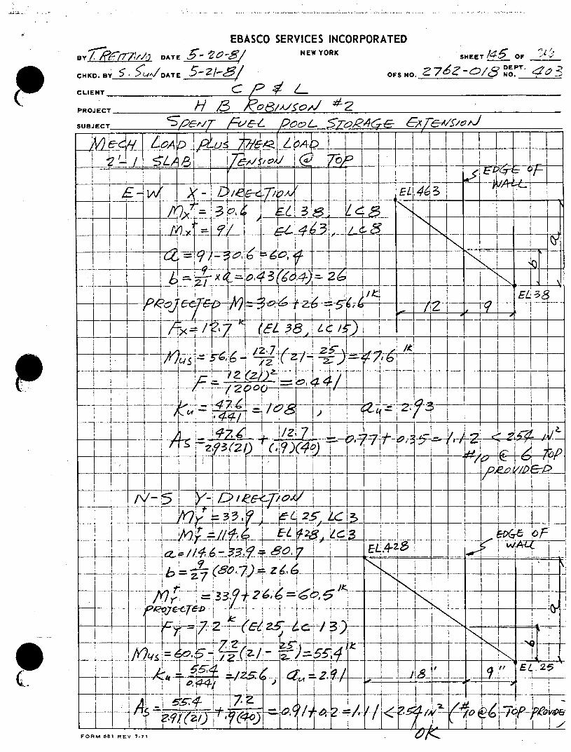
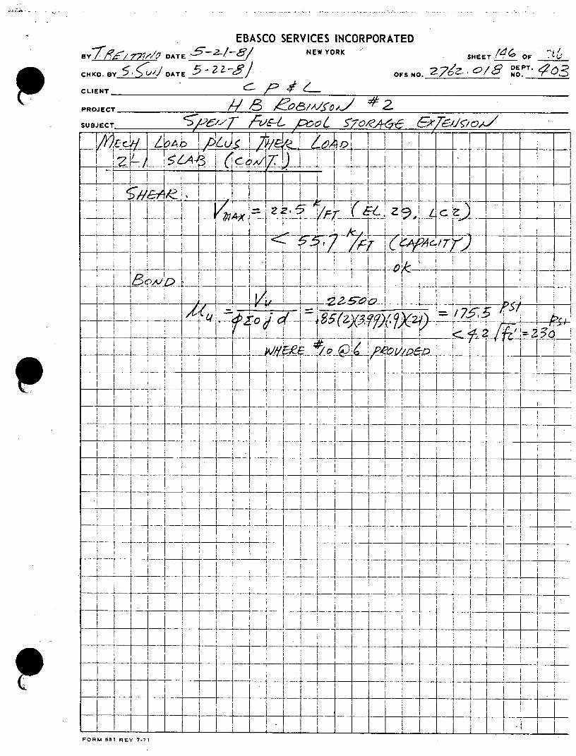
Yes, the floor and foundation slabs have been analyzed for the new column loads and the calculation sheets (Attachment 2, pages 132-148 and 180188) are attached. Calculations are shown for the floor slab internal forces due to maximum column loads combined with additional concurrent loading on the floor slab. Reinforcement requirements are specified to adequately resist internal forces. Also shown are detailed calculations for foundation slab supporting piles.
10. NRC Question
How is the load transferred to the slab, pilings and soil?
CP&L Response
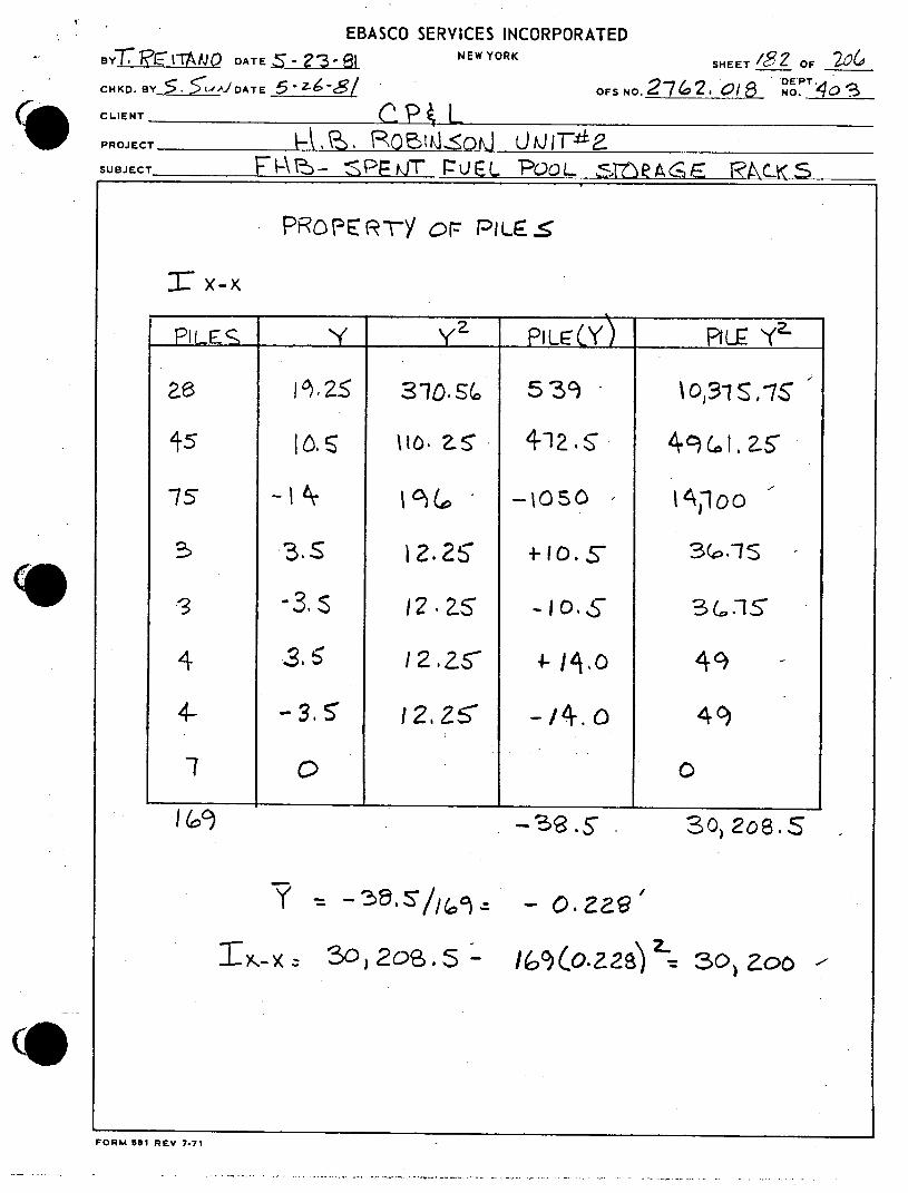
The column is secured to the foundation pile cap by means of a two (2) inch thick steel base plate and four (4)-1 inch diameter concrete anchor bolts. Column reaction loads are transferred primarily by compression under the base plate through the four (4) feet thick pile cap directly into the supporting piles beneath the column. An attached sheet, (Attachment 2, page 180) indicates that six (6) Type 5 compression piles are effective in transferring the column compression load to the surrounding soil. The attached sheet, (Attachment 2, page 186A)

calculates a maximum factored pile load of 207 kips in these piles leaving adequate reserve from the specified ultimate capability of 225 tons or 450 kips (FSAR Section 5.1.2.6, page 5.1.2-16) and the specified factored capacity of 169 tons or 338 kips (FSAR Section 5.1.2.4, page 5.1.2-13), utilizing 0.75 capacity reduction factor as specified.
11. NRC Comment
Provide more information on the details of the connection of the column to the slabs and itself.
CP&L Response
Details of column connections are shown on Drawing CAR 2762-B-410, Revision 1, dated December 4, 1981, (Attachment 3).
12. NRC Question
Why is the column needed?
CP&L Response
The assessment of the feasibility of increasing the spent fuel storage capacity from 276 fuel cells to 544 fuel cells included an evaluation of the load capacities of the existing supporting structure and foundation. This evaluation included a complete finite element analysis of the spent fuel pool structure with the latest Westinghouse arrangement of fuel cells (534 fuel cells + 10 spares). The evaluation indicated that with the addition of a single (1) column support for the fuel pool slab, acceptable safety margins were maintained for all portions of the structure including the foundation piles.
The detailed analysis revealed that a single (1) column support was preferable to a double (2) column support system for two reasons: 1) when two (2) column supports were incorporated into the finite element model (between Gas Decay Tanks 1 and 2, at the south end, and Gas Decay Tanks 3 and 4, at the north end), unacceptable moments developed in the pool slab in the area of the cask pit; 2) the reaction loads from the column located between Gas Decay Tanks 3 and 4, at the north end, would jeopardize foundation structural integrity as supporting piles do not extend below this area. The single (1) column support at the south end, between Gas Decay Tanks 1 and 2, results in acceptable moments and shears in all areas of the pool supporting structure, while at the same time preserving foundation integrity.
13. NRC Question
Where is the column located in relation to the piling?

CP&L Response
Attached are two sheets, (Attachment 2, pages 18 and 180), detailing the location of the column in relation to the foundation pile cap. Also, see Attachment 4, which is a drawing of the "Fuel Handling Building Piling Plans and Details", Ebasco drawing G-190419.
14. NRC Question
Are the piles held by friction or founded on rock?
CP&L Response
The piles were designed to function by a combination of point bearing and friction in the hard silty-clay layer. No reliance is placed on the upper soils for vertical pile support.
15. NRC Comment
Provide more information on soil structure.
CP&L Response
At the-ground surface approximate elevation 225, a 2 ft. layer of surficial sandy clay containing organics was encountered overlying 27 ft. of loose to medium dense fine to medium sand. Underlying the granular material, a 10 ft. layer of clayey silt occurs having an unconfined compressive strength of approximately 2000 psf. This deposit appears to be normally consolidated. Beneath the clayey silt a 15 ft. layer of dense fine to medium sand containing occasional lenses of non-plastic silty-sand and sandy silt ranging up to 3 ft. in thickness. Underlying this deposit, a 10 ft. depth of very hard silty clay was penetrated having an unconfined compressive strength of about 4000 psf and which has been subjected to a preconsolidation load of at least 6 tons per square foot as determined from three consolidation tests carried out on undisturbed samples. This material overlies a very dense fine to medium sand layer having a penetration resistance of about 100 blows/foot on a standard split spoon sampler. This layer is 10 ft. in thickness and overlies numerous very dense sandy silt and sand layers to a depth of about elevation 132. Various other high density deposits were logged extending on down to the bottom of the deepest hole at about elevation 77.
lle

0
ATTACHMENT 1
H. B. ROBINSON UNIT NO. 2
SPENT FUEL STORAGE EXPANSION REPORT
REVISED PAGE 4-5b

39) 1.4(D 1+D2)+1.4To
40) 0.75(1. 4 (Dl+D 2 )+1.7(L+L 2 )+1.9(EO-NS+EO-NS,+EO-VERT)1.04To)
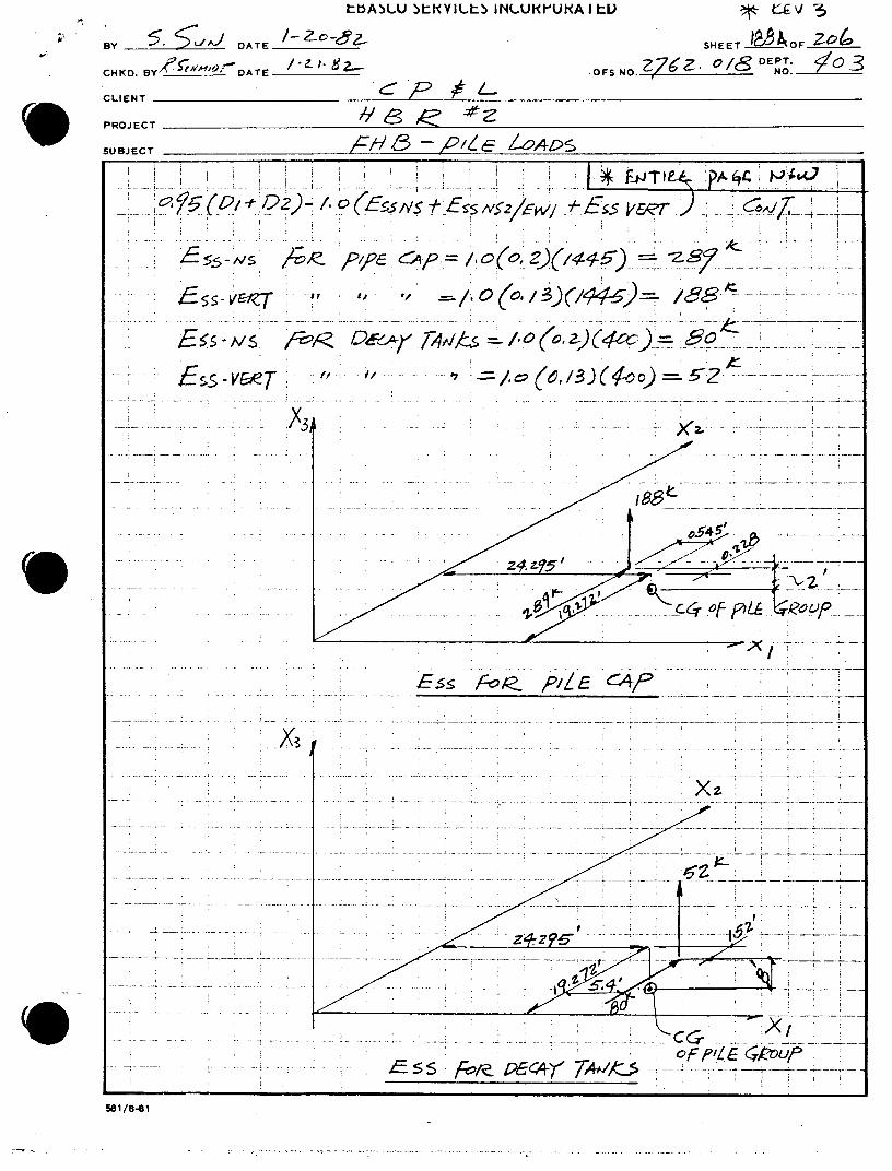
41) 0.75(l. 4(D1+D2 )+1.7(L1 +L2 )+1.9(EO-NS+EO-NS2 /EW1+EO-VERT+1.04T ) 42) 0.75 (l.4(D+D 2 )+1.7(Ll+L2 )+1.9(EO-SN+EO-SN1 /WE2+EO-VERT+1.4T ) 43) 0.75 (l.4 (D1 +D2 )=1.7(L1 +L2 )+1.9(EO-SN+EO-SN2 /EW2+EO-VERT)1.4To) 44) 0.75 (1.4 (Dl+D 2 )=1.7(L+L 2 )+1.9(EO-EW+EO-NS2/EW1+EO-VERT)1.4T ) 45) 0.75(l. 4 (Dl+D2 )=1.7(L1+L 2 )+1.9(EO-EW+EO-SN2/EW2+EO-VERT)1.4T ) 46) 0.75 (1.4 (D+D 2 )=1.7(L1+L2 )+1.9(EO-WE+EO-NS1/WE1+EO-VERT)1.4T ) 47) 0.75(l. 4 (Dl+D 2 )=1.7(L1 +L2 )+1.9(EO-WE+EO-SN1 /WE2+EO-VERT)1.4T ) 48) 1.0(D+D 2 )+1.(L1+L2 )+1.(ESS-NS+ESS-NS1/WE,+ESS-VERT)+1.T 0) 49) 1.0(D1+D 2 )+1.0(L+L 2 )+1.0(ESS-NS+ESS-NS2 /EW1+ESS-VERT)+1.0T ) 50) 1.0(D,+D2)+1.0(L1+L2)+1.0(ESS-SN+ESS-SN2/WE2+ESS-VERT)+1.0To)
51) 1.0(Dl+D2 )+1.O(L+L 2 )+1.(ESS-SN+ESS-SN2/WE2+ESS-VERT)+1.0T ) 52) 1.0(Dl+D2 )+1.o(L1+L 2 )+1.o(ESS-EW+ESS-NS2/EW1+ESS-VERT)+1.OT ) 53) 1.0(D1+D 2 )+1.0(L+L 2 )+1.(ESS-EW+ESS-SN2/WE2+ESS-VERT)+1.0To)
54) 1.0(Dl+D 2 )+1.o(L+L 2 )+1.(ESS-WE+ESS-NS1/WE1+ESS-VERT)+1.OTo) 55) 1.0(D,+D2)+1.0(L1+L2)+1.0(ESS-WE+ESS-SNi/WE 2+ESS-VERT)+110To)
Load combinations for the steel column are as follows:
At normal AISC Working Stress
1) U=1.0(D2+L+L 3)+1.0FC (LO=0 During Cask Impact)
2) U=1.0(D2+Lo+L 3 ) 3) U=1.0(D2+Lo+L 3 )+1.OW-NS
4) U=1.0(D2+Lo+L)+1.W-SN
5) U=1.0(D2+Lo+L3)+1.W-EW
6) U=1.0(D2+L +L3)+1.W-WE
7) U=1.0(D2 )+1.0(EO-NS-EO-NS,/WE 1+EO-VERT)+1.0FC 8) U=1.0(D 2 )+1.0(EO-NS+EO-NS2+EW1+EO-VERT)+1.OFC
9) U+1.0(D2 )+1.0(EO-SN+EO-SN1/WE2+EO-VERT)+1.OFC
4-5b

ATTACHMENT 2
H. B. ROBINSON UNIT NO. 2
SPENT FUEL STORAGE EXPANSION
NEW COLUMN UNDER FUEL POOL FLOOR
EXPLANATION OF ATTACHMENT 2
CALCULATION BOOK HB-102
Pages: 18, 132 - 148, 180 - 185 185A, 185B, 185C, 186A, 186B
187A, 187B, 188, 188A, and 188B

EXPLANATION OF ATTACHMENT 2
The following computation pages are excerpts from Calculation Book HB-102 and detail the analysis of the fuel pool floor slab and pile cap.
The column support, as indicated on page 18, was included in a finite element model of the spent fuel pool. Primary loadings (i.e.: dead load, live load, wind load, seismic load, etc.) were input into a computer run and then combined with appropriate load factors to determine the governing maximum internal element force envelopes. These resulting enveloped forces are shown on pages 132 through 148 for critical load combinations (LC1 through LC55, as applicable) for both mechanical only load combinations and mechanical plus thermal load combinations. As the support .column was included in the finite element model, resulting forces in the fuel pool floor slab reflect the effects of the column reaction loads. From the critical force envelopes, the existing concrete slab and reinforcing is checked against that required in order to verify its adequacy. Inspection of pages 132 through 138 shows that both the concrete slab and its reinforcing are adequate to resist the effects of maximum factored loading combinations and the column reaction loads.
The effects of the column loads on the pile cap and piles are detailed on pages 180 through 188B. Maximum governing load combinations are determined from the computer output reaction forces and transferred to the pile group center of gravity so as to predict maximum and minimum pile loads. The loads O in the six (6) piles beneath the column reflect the effects of both the maximum factored column loads and the maximum factored load combinations from the computer output. Inspection of pages 180 through 188B shows that pile loads do not exceed acceptable capacities for both axial and shear force effects.

EBASCO SERVICES INCORPORATED
B3y C~ -' DATE NEW YORK SHEET '8OF _____ 5- '8 OFSNO. 42 76 7O~ DE PT.
0HK. BY ___ DATE ____O. _42 _76_______ NO
to CLIENT
PROJECT
SUBJECT 1Cg C/ X-''9-&L
Aa
10* 4
Vi
-Ja
0777" .~ ...
FOR 59 RE 77

EBASCO SERVICES INCORPORATED eY . .- 1,7s~ AESHEET OF____
_______~~O DAEOS0 2DPT. CHKD. BY DATE___ NO. N 6 ( ~CLIENT 1/
PROJECT /'82
SUBJECT____._______________
7-i b~ ~Lb,46 ~ A/~-1 141e-Al o7
AHi - I--- T' AFr
-_ /67-- c
-415 7. ( I~0 -1a ct,________
- :~ 7 ,iZ~c'4-

EBASCO SERVICES INCORPORATED
ByDATE NE OKSHEET __33 OF ___
CH KD. DTOFS NO. NO'. /8 DP. 3
CLIENT
PROJECT /' i
SUBJECT (:;76 CeT6rl( PIa/ Al~465~
~~120co
-T- i~i~if~ ~----
7_ I
-,7 -74
I~2 VLt-a
er F-4 -_ _ ___ c
-4- 7___ A/
- rK~ 9I~zi7 1i 1j
FOR-- REV 73-717

EBASCO SERVICES INCORPORATED
________ DATE 5i E YR HEET/Y OF___
'74z,62/5DEPT. CHK.B ATEOFS NO. 7/ 07/, NO. ____
PROJECT /', SUBJECT__ ~~ 4 Z/A&6# 'i'
-- T1.!I~
~~~- --------- A/- I
TT
FOR 6 1 RE 71 1

EBASCO SERVICES INCORPORATED
DATE NEW YOR SHEET OF __
CHKD. BY .L'DATE 52 -/OFS NO. CN6zE PT.~ ~
(C LIE NT Z
PROJECT / ~ )CSAS'/~
SUBJECT 5~/ -/6p'' ?/ $~ 4 ~-/~
Z9'~ ~±~ FV' O4JA/! >2 E I ____ _ I IT+ __
I __ __ I I L~~JLi
2 EL.k4~12/~ 6 ~ Ia~+ 7
T7 4)
'Iiof -0A/K _
2 2_
14L L- I -
F
6-o o) 17 -L~)
T ' IFO
J8 E 77

EBASCO SERVICES INCORPORATED By DATE -/ - NEW YORK SHEET/34 6 OF
CHKD.BY 5 VDATE5o8/ OFS NO. 2-76e?-O " qq CLIENT
PROJECT A/ 9 //A/;aA/
SUBJECT 5 PooL S7
L / 31 -E24/ cL4T 13.03~ IT~,~~---I
_ ii'I < L-
woo
O 7 -7
I~~l. 0,l-~- -el -
-- t - --- L i . ......_I
FOR 81 REV --7

EBASCO SERVICES INCORPORATED 0 y:iLy' DATE £iz~~ E OKSHEET/ 7±Z OF ___
DATEOFS O. 27 Z DEPT. -40
CHKD. AEOFBO Y' L .c NO.____
CLIENT
PROJ ECT //3 ,& //'' SUBJECT /C TF-& ,cc6 A & t*77/o/
7TilI t-4 IA%7Ii ~ nf~ 7
7 _ T
-2--3
I A '~ 31.34---- -hi LVT
a- rr''' IT
4--- ~ ~ 5(i - I rijjj-~ I
It 40-- J
FOR 58 REV--7

EBASCO SERVICES INCORPORATED By _____ DATE 5'-i-iNEYR SHEET/? OF
'2 DEPT. CHD Y AEOFS NO. NO. ____
CLENT c:
PROJECT
SUBJECT 51 67L&5 -oo 7___
A_1 T i -1--- LL
- -__L~c L~j~/s ~//~*4 -A
~~F c 142 7A j~I -i9~
1 7 -/
I ~ - -- ~ -<I-2 NQ
I ~ ~4 2,9 ZI;~~~w L'- ~ 1~
___ ~ 1 ___ ____ ~~A - b*- -
-011~7r// 111
FORM :t8i RE 7-71L

EBASCO SERVICES INCORPORATED ~ D~ATE 5/ c~ E OKSHEET/1 9 . OF
*~-7-~2 5'~DEPT. CHKO. BY_______ T OFS NO. 27492' fL.A5 NO. ____
CLIENT
PROJECT / 78A ,~ SUBJECT Roo c6 c
-I _ _
h ~71
-~~- -C
I I I __ -I
- ~ ~L
tOR 68 REVV~ 7K-7-

EBASCO SERVICES INCORPORATED
BY777/0?EC?1~kVATE -2 5/EWRKSHEET 40_ OF___
a -7- DEPT. CHD yDATE __ _ _ _OFS NO. 2 c NO.
CLIENT
PROJECT 6& A'//cA
SUBJECT !2&?oT/ 1,5clc6_
IA 9Z- Eh _
I~ _0 !T~Q~ 1~- / 134 -- I
I r
T - 4 _ ~~ t
-i L 62I
FOR del-i REV 7-7

EBASCO SERVICES INCORPORATED
-eYf I? /O ofrJ DATE NEW YORK SHEET OF _._
CHKD. BY DATE OFS NO. NO, /8 D.PT.403
PROJECT // 8 /d50/
SUBJECT_
e4q0 h9 R. 7 t - X A -- -2jI--I
AT T j
4,7:5)( __0, 7, -- I _4 / o 14/ 98
7--2 i- j
- AI
ORM 8 -EV 7-7__1
I~~0 *5 .I
FOR -8 RE 77

EBASCO SERVICES INCORPORATED BY.22~5LZ~4 Q DATE NEW YORK SET~O __
CHKD. ByDATE O NO.NO._NO.
(CLIENT PROJECT 1 8As'/ 2
SUBJECT O ~~j~/'
41Lv x 4-/
I K
E-Z~ N2/, Jf jF ~1 717 ~ 1,.C~-i~2i&- l o$/
IT f.=-s'.>-. ~~ . .I . .i s
Iz~ c ~ S L'O~i~ _ KA
~&~:{ ~__ 4
-- F--7 353/3' z _

EBASCO SERVICES INCORPORATED
Bv 7Rr ov'p DATE NEW YORK SHEET 13 OF
CHKD.BY DATE 5-2/-8/ O.z N/8 .
CLIENT c
PROJECT / /8 4CV#
SUBJECT A// T~ . 0' ~ ~ _ _ _ _
su ei o 'I5ro-F-/
8 (. - - - -+
ethe
I1 4I ki i
.411 KP H VZ~ -T- t -~-I--I__
Hill. /

EBASCO SERVICES INCORPORATED BYZ 7--1;'710A T E -209-& NEW YORK SHEET OF_
$ DE PT. CKD. BY 2~/DATE 52-~~ OFS NO.f''c2 No. ___
CLEN ZSl z zv _
SUOJECT
I -7 tA ~ iQ ..
_ _ _ _ _ _ _-4-- -k ---4 _
4_3 -7 1 ~ __ r~~j71-r
.4 AlI]
FOR 356 1E 7v/--71'
EBASCO SERVICES INCORPORATED BY! DATE ~NEW YORK SET ~ ___
6, SDE.PT. CHKD. By .5#V DATE OFS NO. NO'~
CLIENT
PROJECT /1 82~c&~- A SUBJECT _________________________
Hi Toi-Ii EL38$
(fL3~I~c#M
7-2f
FOR :1 REVj7 7Z 9 71/
EBA.SCO SERVICES INCORPORATED ByDATE NE OKSHEET ___OF ~
CHD DATE _____OFS NO. NO.c/6 P. ~~
PROJ ECTA/5
SUBJECT__
Ti2 - t~ -AX i{-- -1
I~~-_7 A-) - 1i __
Ft -1
FOR 68 RE1 -7-71

EBASCO SERVICES INCORPORATED BY7RE7VVO/ DATE 5-2?3-6 I NEW YORK SHEET 1i70OF e7__
CHKO. BY1j&Ljj..L DATE ______OFS NO.2.ZNOL8 .4
CLI IENT rp~'L
PROJECT ?iio 2.yot 1%,A11r
SUBJECT A/B- S IV7-A SZ F2L7W,& 9/<
z "-7 3
0 "
vlEsr WALL FZ,'4ELf4 ,p 6,
FORM 5^1 REV 7-7

EBASCO SERVICES INCORPORATED BY.ZT LZ ODT NEW YORK OFHEET_
0/ DEPT. CHKD. ByJA) L (L4 DATE _________l OFS N O. 6 ? No.
( ~CLIENT Pf PROJECT /1.B. R/03 A% 6dA/ &W,17- aSUBJECT S '67L R7C<
AVr4L cf 'ce 77 CoLtzM.viP= /9 <
5/v. 7-,/E: 4X/sU- 11VidL 74/716' (2e l.A4
c0 Z> etS RE4 cpui 'Ar A/1E 2D 7Z:> E-?CC'.7
r--o? IA ,i /A 7W 48. A7Z 1 A L F2c 1v 6l AurplCD- E 8>/X 4. c7vf' a,~/--5
(~~~~~' us,! /R /S,/5S232S 29s.KI
1.q - 5 5'O 83pi .L0~
2 - 00 &)~)- ~. (y8
-6/60'
Co

EBASCO SERVICES INCORPORATED BYAF77fA DATE 5-23--/ NEW YORK SHEET ____ OF
CHKD. BY .1 'DATE OFS NO.272016 DEP
CLIENT L
PROJECT HI /31 SUBJECT F-18 - 5 PE17V Fl/E L PoL ST 20Fr-E RA C5
PI..E. ARRME~JT
-6--9 -.-
0- 0 ---
--- -e-e & --- I 0
-0--0 00 - -0 -0
e ez oo
-6--0---0 0-- 0REV0 - 0
- -0--&-/&2--P-- 3'- - - 'I FoRA st as97.7

EBASCO SERVICES INCORPORATED BY F5Tt~ AE-52 - 1NEW YORK SHE/2/ OF _2__(
CHICO. BY_ DATE 5-l8 OFS NO.2l 0 . ~4a * CLIENT Cp4L
PROJECT H4. Ro~iwsoi1dJ\o SUBJECT 6F\A-- 5PFTQLEl- POOL 675RA6i.: 5k.cZK5
IL L5 X PIL-, Pl $X
- ?.s' 637.54 --7, -71,7
40 1. S7 1.(~z - Z..
52 i-I+ 2),5 /(. 03
C5 c2.15" 14Zs05..79 T,E
4VI"-~ G9E A sMALL
154 CZ /fX 3 74
Tiy-v y ?4,50,5.7 9- 1 ( 5 )-Z 425CC
FORM 581 REV 7.71
EBASCO SERVICES INCORPORATED ay?1f~r~j O TE~3jNEW YORK SHE20(OF__
CHKD. BY LADATE 56 cg OFSNO. 2 7(o2o c'i8 NO.P
SCLIENT cP L PROJECT 50d O~~Ea UWTJFFk SUBJECT F pp-~ tPjT p POO ?QL STln A - t\(S
PROPE'rc o PILES
x 5 - lYpo
14. 3-7. 5 ~-3c 0 1 -,
4-0 -. I2-5 -4. 4c)
-15 C) 0
FORM 581 REV 7-71

EBASCO SERVICES INCORPORATED BY DATE 5'fd NWYR SHEET ___3 OF 0 CHKD. BY 5 U/DATE ~~8OFS NO. (4AAZ 27,,? 0 'DEP. ' CLIENT C/)'c
PROJECT
SUBJECT 4fA'- &90
77kK~~~~~~~ 0?7cJ~ 729~z ,4,0 5 J
3 0
EL 0
/~ 6Tto I_ ,~ 4i-.9 3 /~3 ~W9, Z6 392Z.
C. r<12. 4, a. -176. - 5, /g. Z,729, 0
6. w ,d?,4cecS 1- 6.c. -633~*-S. &SZ '~9. 7 vwo vS s iV wlv . _Z 0. /Z,%9. -429. -3,4 Z7.
/"1 "/Ea/' -171 -~//19, 40. 163. -/a,,573, 2,4 ?Z
// r~~,g~ ~-AJ 0 //G. . 44, 0. 6!g
0266"./46) 23( . -7o19. 507$. 95 ..- 3,347 1& Vg-4rEj O4A 5z16 ,8/ . 0. 0Z. 164 4 . o3,5.
Al - W6 v04o -Z 3 4. 0.6- 6 ~3. 56>'Z 3A. &
A~iWAL((~L -9o. 9o. -834. 16,,z3. 45C'L- /4b97
5 Avew 556 3AI/cd . 390. - 834-. 03pC~ Z-3 -13~3 2/ Sk 5S VSV 5v 39o. -390. -867. -/q .o,, z/9 o /f~l
5, A6- c4 e'f/2c 57Fc. --~ , //7~ 3> 3 3g ._
FORMd ,1- 5. 36 REV, 747 1130 - J33,

EBASCO SERVICES INCORPORATED I
BY _____ DATE 2 ,lNEW YORK SHEET/f. F o ? ___
DE PT. CNKO. BY52 -A DATE 5OFS NO. C,4 4 276 2. CdIY NO. ____
CLIENT PIL 0 //_ 2 PROJ ECT
SUBJECT - P' - 0 ,c4L)5
6DP7. 3.
/134 5;! ____ 7, -34702. 393oo'53 Z24+,3S,
Z. LIoZ_ _ -S63- -9(, 7, 19,751. 0.
Z- 0. c -- /V- -),32I8. 0
__ _ __ _ __ -- 0.. 70. 1- 1-399,03 14-42,-)Z.8. 1
e: Z~t, - Z.7~/~) D,
3:' 31,94
I4Xj: 4427?
-7 X
4A-1-5 X.~ -r> c-f P~ILE ckjp, (i.X4S.,0X 5-3S4x 4-O 0 5): z 27. y
FORM 581 REV 7-71

EBASCO SERVICES INCORPORATED 2 NEW YORK
evBY _____o__ DATE NE YORK _ SHEET /85 o __2__
CHKD. BY ,2 '/4 DATE OFS NO. (CA, Z7 oZ NOE. _ _ ' CLIENT
PROJECT
SUBJECT / p'
Zd 71 veL47/O; (or.)
SA. /5. 5. orp. 3-i- 8Z
JL/5 . £C. 2.4 7as' L--ld/+/oi 7 5 v /a
+-Er4 ) /.
/ 0/ - 994 /13,170. -297,42. 277, II8. 18, o4-.
4 02 -4BS;. to.__ -477. -6,90. -it&.* %;S.
___ ocyi 7,'-Orz I akr /,'M /1 / Af2 /. a$,r? 0, -313. -5343. io,995. o.
/ E 5 -lf/ A 3 0 , 3 jo , -g 1 ,294, 2 1;oC p, 3 8
zZ F c. c. -3S. -lo 79. 5(c 3.
_____ ff;9/ 2.ofrz 2-o/f3 207-// Za/7k2 2.o/-Ar
cs-N o. 3 3 , -87780 . 8230 ft
c Ss-_vir__ 0. - 2,1od. 6 0A. C&iC. o. F=X f1 FXy( 3 m YI M4) Z- t. kg
- 3 4072. -179o.. -42734. 3748$5/25
, y 1(.24- /, (~z oz/wo ESs)*I /aoF
FFLE CAc\0Sw14
FK - 79o0 -7
Myi4 =1 -ft3 I-lo
T4i 5 Loso coZH CAusiS LAq2isr Wvid 3ZY3 AYIAL L OA ft E55 2.0 E '
FORM 581 REV 7-71

EBASCO SERVICES INCORPORATED ~ ~
BY DATE' SHEET-LnOF 7-OCO
CHKD. BYZ-f/' L/du%7TE /F NO.9 NO.~~JDE O ~C LIE N T
PROJECT ' ~ /I~~
SUBJECT F/-fz~coL
A5ss . Fvx~c ,P.'Z C 0 ,2 (4~ '~
LS~a.k -54
~~~A/ ~ ~ ~ ~ ~ j 2V~PA ~k.ejO>'
C/34l>l'
Xz 5z
74 3lk 7o/L~
581/8-81

,0EBASCO SERVICES INCORPORATED 9- 3 BY ~ DATE- Zd SHEET I96.0 OF '
CHKD. BY DATE OFS NO. D72 EPT jj
w CLIENTNO
PROJECT
SUBJECT A;'/21& 54)
.-------- ---- -------P T)
-DT -i iz4-. -.-SS.25/,~ .2-OZ5, 4- Dz -78. . Z'- 5(8-I9 -4 lO& 2- Ll 0. 2 I.C1 11~,-O~ 74+ ~ 00 13 .O~ J .... ........
17~0 384,10..i!9L.7J2 2= 1___ .0r IOxX 1 10 Oi-F3 I-ONXI -0 Y2 IOHX
31A,- io- -7 5 U, 3 0
1- 59 -436- 44,
581/841

EBASCO SERVICES INCORPORATED -e Z, s
-. ' BY 5' A DATE/8
Z <:::41Z 5cETIi OF20
- - .74. c2/,- NOP.___
CHK. BY Lz S NODAT NODPT
. CLIENT
PROJ ECT 45 2 SUBJECT I S P,, -E LcAD
4fNz Z' -C7 01
- 1.125
C ~ri7
Ec'-Ny 7,%4v piz 5-(
.. .. (. . ......... ,
-------- .... 4 0f I L c o
581/8-81

EBASCO SERVICES INCORPORATED
By Z DATE ___c__,__ SHEET ____) C.
CHKO. BY ~ "'DATE / 8 O7S NOA2.0),& NO. 4-()
CLIENT
PROJECT/9__ _ _ _ _ _ _ _ _ _ _ _ _ _ _ _ _ _ _ _ _ _
SUBJECT- ,L L4)
;(vILI
- ~ ~ x~t1 7-S.~- ID:~ ot V&.2
I-X,?2 4052 1-64- -
T.-x 127 - 42
/i~ 2 435 6 1524.o (2~a -,o(.-~t z-9eW,
H~~~~~~~~95- 2/33 /5/'/aZ)4 /(/~S2 5, Z~
40
0. t -0<

EBASCO SERVICES INCORPORATED BY 5 LA DATE NEW YORK SHEET iLFCIJOF Z-669
CHKO. BY ~: ATE OFS-~ NO. ____ NO.. __
PROJECT 'Z 'cd a ,2?& 5 ,/rb, SUBJECT_ -o
1457
I ~ ~ 0 J)2~7~ fr / 25f12 ~17- 7L47
-4
FOR 61 RE 7-4771

EBASCO SERVICES INCORPORATED /'VS
By" ~c4DATE /-2 Z SHEET /S'7AOF CHKD. BY - ~~DATE / 28 OFS NO. - NO
CLIENT J i PROJ ECT ________
SUBJECT-/L &9
Al -- , -72,0
/0 /8c3 74 -yo /~* p (3-.' 4/L)f
3& 7
7 ~ ~ 3
581/8-8

* EBASCO SERVICES INCORPORATED AV 3~
BY DATE -(f,4 "; SHEET O
CHKD. BY _________ - OFS NO. NO.. / D P :
SUBJECT r~ /
4Z3 -, - 26 4 -.9 +42Jhu : ~~-Z,-c9 1, K_
-, 086. () Z + L2,# O(5Z)-2d2)-6 3(9) 574.
q ~ ~ = 72
2Z577. 6-7 _- _1 _(4?__2
744/ _______65______0,
30 zoo4245o
2Zc77 5744 21-0.2ZS) -jI,(25 .2 5 -205
A~~f4 44
Z~ -, IZ45 a C.) e-,
'4
7Ce 37 5817a-r

EBASCO SERVICES INCORPORATED* Y3
BY z,____. _ , D ATE 2- SHEETL2. OF ___
CHKD. BY/? ~ D DATE _ _____OFS NO. NO. 2$ E: O CL IENT
PROJECT
SUBJECT Z// L-; Z,4 0 S
/IA ID 7iuLA7/ /k2xC&
Asp~' /---/~c& -- - ---
6fo141S2,hA7cJ A C.6CJB V/?7&?T
C-A -,X LO 0£f '?5 FA C'.Y5 FX'3 0, 5 lvl ,f l)X5 Ai
2_0 '2FX, 10F FXX // 0oX M/ /ix / zA2X
Z/1 -(-6$ C ?78o - q7
/7 E- c 270.6 + 5o2?4 -,,97741,
__ ___ 'FX, b 0 FY4 b/.FX-s /.oN, /.OAIxz. /',)X / 5.~/w/~~-867 -&~2 '4 21,071 /33,5
- - -tX~/o3 .
I -
----------t~~1X AD9 71 ?'~Co
#fALo -OF < W4(c 4Pco~38 P.L tCAe/ f3x41 -)
tbANLU tKYILtNINLURF-UNA IL tV-L-A
By!5 DATE____ SHEET 'M/kOF 2s
CHKD.BY DATE 8..-OFS NO.' NO.
CLIENT ' PROJECT
SUBJECT F/ t R8IZE Z-0.AP>!
A. -Ppc o "'0
XXz
-opi~(Iof
5-540,/8ZE4:14

EBASCO SERVICES INCORPORATED CE v?~ 3 BY _____ DATE 1--21-__2 SHEETA OF
/_ _ -_ __ 21- -- / DEPT. c 3 CHKD. BY4 ,id DATE OFS NO. NO.
CLIENT
PROJECT /3 Z
SUBJECT H1 P'& rADS
-3 FXz-40al7 Zgl*c oz 4436
FX3 166/~+ &
NX 29% 757Y40e,7(4-0) *o(.z2z) 1 372 (, zz 8) .?S380
A-2~~~~~~~i8 oz6ZozZ47 z. -2) *' r-57
60-~ -2 . ~-37 <fA/Yd
... . ....... ~
501/8481

ATTACHMENT 3
H. B. ROBINSON UNIT NO. 2
SPENT FUEL POOL AREA STRUCTURAL MODIFICATION
DRAWING CAR 2762-B-410-R1
S

r REFERENCE DRAWING:.
PLAN-GEN ARRGT-FUEL HIANDLING BLDG& "MACHINE SHOP :G7190 192.
LUJ
I-4
.. 38 Qb
TA4K ~ fA~~~
NN/T9
SECT D 'c) 11Nt2)x, 9
GNE-:AL R VISI'IN "45 CIR.CLE
INCHES I2 CM. t A

NOTES.
1. ALL STEEL PLATE SHALL BE ASTM A-36.
2. CONCRETE W DGE ANCHORS SHALL BE 10 X 12 WEDGE
ANCHORS NO. WS-1.00120 AS MANUFACTURED BY
PHILLIPS DRILL CO. OR APPROVED ALTERNATE.
3. GROUT SHALL BE MASTER BUILDERS EMBECO 636 OR
APPROVED ALTERNATE.
4. WELDERS, WELDING OPERATORS AND WELDING AND
WELD PROCEDURES SHALL BE IN ACCORDANCE WITH
! TC)L POOL I Al AWS D1. 1.81. STRUCTURAL WELDING CODE
5. WELDING ELECTRODES SHALL BE AWS-A5.1 LOW
HYDROGEN CLASS E70XX. FOR MANUAL SHIELDED META
TYP ARC WELDING, OR AWS-A5.17 F7X FOR SUBMERGED
ARC WELDING. 6. PREHEAT IS REQUIRED IN ACCORDANCE WITH AWS
D1.1.81. TIABLE 4.2,GROUP 1.
7. ALL WELDS SHALL BE INSPECTED BY THE LIQUID 4 PENETRANT METHOD .IN ACCORDANCE WITH ASTM E165..
8. ALL MATERIAL SHALL BE FURNISHED WITH A
CERTIFICATE OF COMPLIANCE.
9. ALL COLUMN ENDSAND CONNECTION AND BEARING,
PLATES SHALL BE MILLED TO BEAR ON ALL METAL
T. .TO METAL CONTACT SURFACES. 10. FOR SURFACE PREPARATION AD PAINTING, SEE
00 EBASCO SPE"IFICATI.ON.CAR-HBR-C-4 .
11. FOR BILL QF MATERIAL, .SEE BM-410.
12. INSTALL UPPER COLUMN SECTION. FIRST,UTILIZING\ WEDGE ANCHORS FOR LEVELING. AFTER GROUT HAS
THOROUGHLYj SET, TIGHTEN WEDGE ANCHORS ACCORD
ING TO MANIUFACTURER'S INSTRUCTIONS..(250-300
FT-LBS). THEN SLIDE LOWER COLUMN SECTION IN
___________ PLACE, BOJT CONNECTING PLATES TOGETHER USING./
A325 BOLT9 WITH TURN-OF-NUT METHOD OR LOAD
INDICATOR WASHERS. INSTALL WEDGE ANCHORS, GROUT, AN6, AFTER GROUT HAS THOROUGHLY SET, TIGHTEN L WER WEDGE ANCHOR NUTS TO 75-100
FT-LBS TO QUE. UPPER WEDGE ANCHOR.BOLTS ARE
NOT TO.BE USED TO HOLD ENTIRE COLUMN IN PLACE"
DURING GROUTING OF BOTTOM BASE PLATE. JACKS
OR WEDGES MUST BE UTILIZED. TO ENSURE NO
~COL TENSION IN COLUMN. 13. GROUT FOR UPPER AND BASE BEARING PLATES MUST
- Q , BE INSTALIED IN STRICT ACCORDANCE WITH MANU
-. __ FACTURER'S INSTRUCTIONS TO ENSURE FULL AND
COMPLETE 9EARING.
PROFESSICNAL
SECT G(2oREQD N "~'9 _TS*A
EBASCO SERVICES INCORPORATED CAR'OLMA FOWER L> ,, POBIN ON M TEAM ELECTIC PLANT-UNIro CA R '27
v FUEL HANDLI0 bulDING
SCALE APPR C.- 9L;PENT FUEL FOOL ARE4 A .41O COVE DAT, eG C ATRUCTURAL MODIFICATION

ATTACHMENT 4
H. B. ROBINSON UNIT NO. 2
FUEL HANDLING BUILDING PILING
PLAN AND DETAILS
DRAWING NO. G-190419
0