Embed Size (px)
Citation preview

Presented by
Knightwatch Ltd.
INFORMATION
AND
INSTALLATION
STUDY GUIDE
1
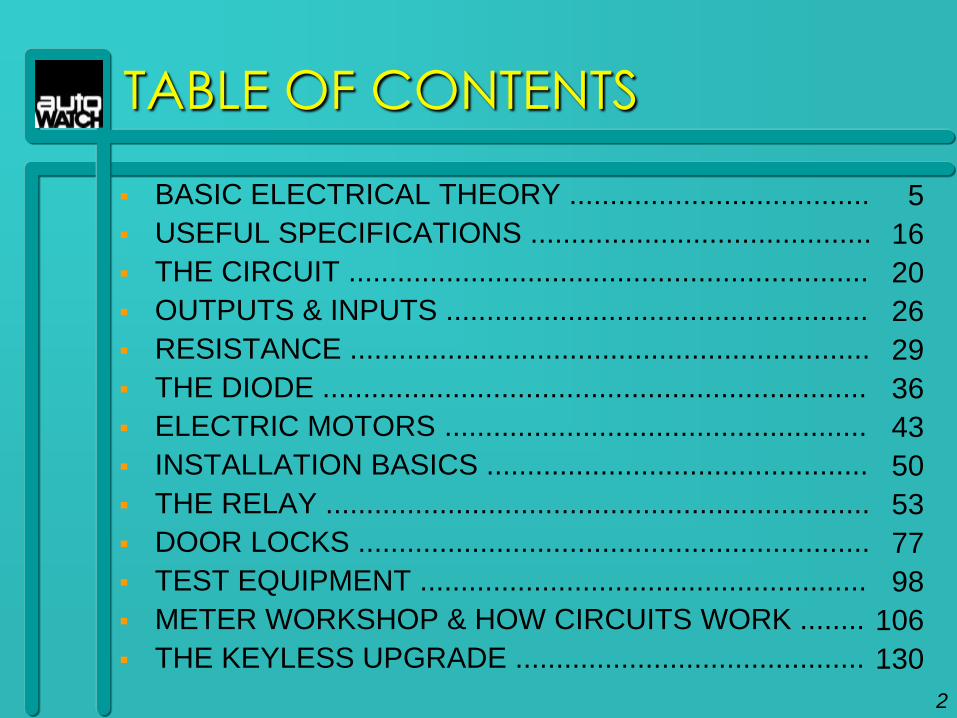
TABLE OF CONTENTS
BASIC ELECTRICAL THEORY .....................................
USEFUL SPECIFICATIONS ..........................................
THE CIRCUIT ................................................................
OUTPUTS & INPUTS ....................................................
RESISTANCE ................................................................
THE DIODE ...................................................................
ELECTRIC MOTORS ....................................................
INSTALLATION BASICS ...............................................
THE RELAY ...................................................................
DOOR LOCKS ...............................................................
TEST EQUIPMENT .......................................................
METER WORKSHOP & HOW CIRCUITS WORK ........
THE KEYLESS UPGRADE ...........................................
2
5
16
20
26
29
36
43
50
53
77
98
106
130

PURPOSE OF THIS MANUAL
To teach the essentials of proper installation
To help make your job easier
To make you more valuable as an installer
To make you and your company
more profitable
3

SUPPORT AVAILABLE
4
Technical Support Telephone Assistance
Main Contact Number: 01732-886777
Staff are available to answer calls 9:00am to 5:30pm,
Monday to Friday.

BASIC
ELECTRICAL
THEORY
5

BASIC ELECTRICAL THEORY
HOW WAS ELECTRICITY DISCOVERED?
2000 Years ago Thalus Miletus rubbed amber (a plastic like material) and wool to together. He discovered the first form of electricity - static electricity.
Next big discovery was by Allesandro Volta, who discovered that when two different metals were brought together in the presence of an acid, electricity was produced. The unit of electrical pressure was named VOLT in his honour.
The first battery consisted of lead and copper disks sandwiched between salt water soaked pieces of paper.
This is considered the most important step that moved mankind into the modern world of electricity.
6
BASIC ELECTRICAL THEORY
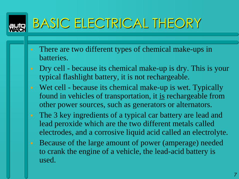
There are two different types of chemical make-ups in batteries.
Dry cell - because its chemical make-up is dry. This is your typical flashlight battery, it is not rechargeable.
Wet cell - because its chemical make-up is wet. Typically found in vehicles of transportation, it is rechargeable from other power sources, such as generators or alternators.
The 3 key ingredients of a typical car battery are lead and lead peroxide which are the two different metals called electrodes, and a corrosive liquid acid called an electrolyte.
Because of the large amount of power (amperage) needed to crank the engine of a vehicle, the lead-acid battery is used.
7
WATER
FLOW
HOLE IN PIPE
WATER FLOW
PRESSURE
BEING
APPLIED
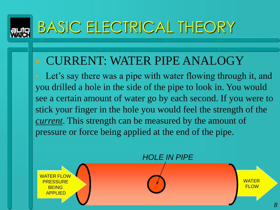
CURRENT: WATER PIPE ANALOGY Let‟s say there was a pipe with water flowing through it, and
you drilled a hole in the side of the pipe to look in. You would
see a certain amount of water go by each second. If you were to
stick your finger in the hole you would feel the strength of the
current. This strength can be measured by the amount of
pressure or force being applied at the end of the pipe.
8
BASIC ELECTRICAL THEORY
BASIC ELECTRICAL THEORY
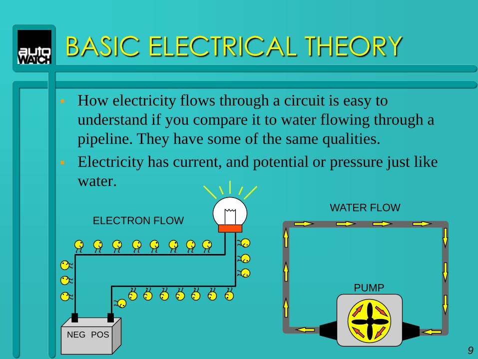
How electricity flows through a circuit is easy to
understand if you compare it to water flowing through a
pipeline. They have some of the same qualities.
Electricity has current, and potential or pressure just like
water.
POSNEG
ELECTRON FLOW
WATER FLOW
PUMP
9
BASIC ELECTRICAL THEORY
CONDUCTORS AND INSULATORS
Electricity can travel through some materials and not others. The materials it can travel through are called conductors. The materials it can‟t travel through are called insulators.
Conductor examples - Copper, Silver, Gold and Steel.
Insulators examples - Plastic and Rubber
Both Insulators and Conductors are very important when it comes to using electrical power.
10
BASIC ELECTRICAL THEORY
AMPS AND VOLTAGE
The flow of electricity through the wire is called
current. The amount of electric pressure applied to
the wire determines the strength of that current.
Electrical flow, or how fast the electrons are
flowing is called amperage and is measured in
amps. Electrical pressure or force is called voltage
or potential and is measured in volts.
11
BASIC ELECTRICAL THEORY
There‟s also a question of supply and demand.
How much power can the power source in question supply?
How much power can we demand from that source?
SUPPLY defined:
How much power is available to use.
DEMAND defined:
How much power can be drawn or pulled from that source.
12
BASIC ELECTRICAL THEORY
The power source being used in an electrical application, is limited to how much power it can supply.
Demanding too much power from that supply can create an overload and cause damage.
Knowing and understanding the amount of power needed to do a specific function is important.
In summary, understanding the terms Current, Amps, Voltage as well as the laws of Supply and Demand are crucial in becoming a expert installer.
13
BASIC ELECTRICAL THEORY
FUSES
Fuses are used to protect circuits, control modules and other electric devices in case of a short or excessive power demand.
Fuses are made up of a special alloy(combination of metals) that is designed to melt or break when too much power is pulled or drawn through them.
14
EXAMPLE
12 VOLT
POWER SUPPLY
POS NEG
10amp
SWITCH
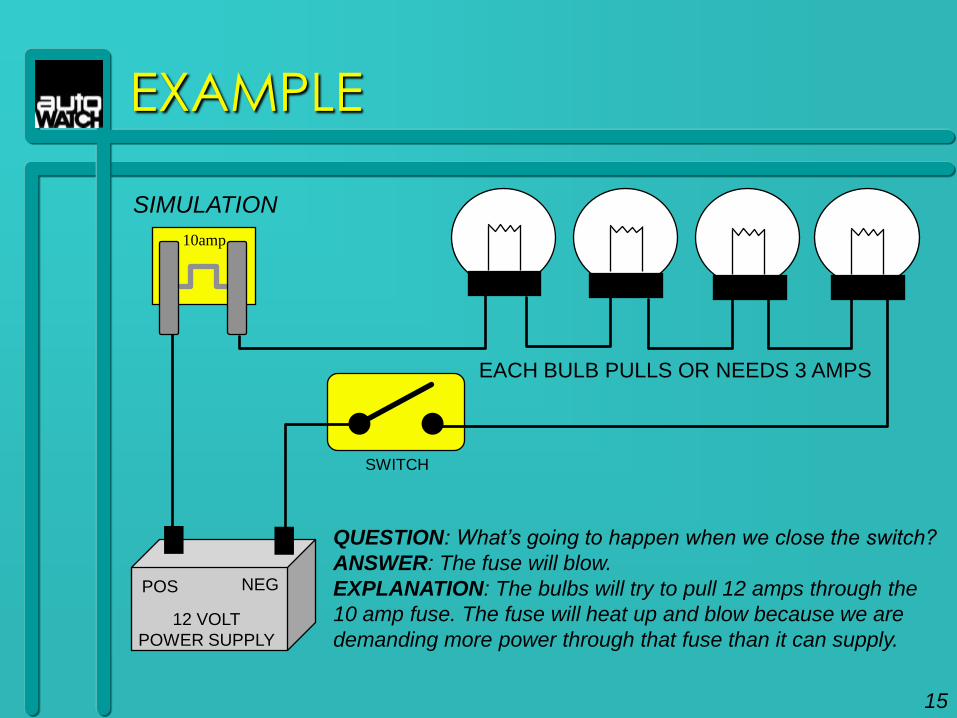
QUESTION: What‟s going to happen when we close the switch?
ANSWER: The fuse will blow.
EXPLANATION: The bulbs will try to pull 12 amps through the
10 amp fuse. The fuse will heat up and blow because we are
demanding more power through that fuse than it can supply.
EACH BULB PULLS OR NEEDS 3 AMPS
SIMULATION
15

16
USEFUL
SPECIFICATIONS
USEFUL SPECIFICATIONS
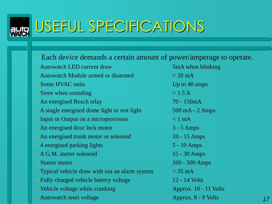
n Each device demands a certain amount of power/amperage to operate.
n Autowatch LED current draw 5mA when blinking
n Autowatch Module armed or disarmed < 20 mA
n Some HVAC units Up to 40 amps
n Siren when sounding < 1.5 A
n An energised Bosch relay 70 - 150mA
n A single energised dome light or test light 500 mA - 2 Amps
n Input or Output on a microprocessor < 1 mA
n An energised door lock motor 3 - 5 Amps
n An energised trunk motor or solenoid 10 - 15 Amps
n 4 energised parking lights 5 - 10 Amps
n A G.M. starter solenoid 15 - 30 Amps
n Starter motor 100 - 500 Amps
n Typical vehicle draw with out an alarm system < 35 mA
n Fully charged vehicle battery voltage 12 - 14 Volts
n Vehicle voltage while cranking Approx. 10 - 11 Volts
n Autowatch reset voltage Approx. 8 - 9 Volts 17

PREFIXES AND ABBREVIATIONS USED
Infinity
M - Mega = x 1,000,000
K - Kilo = x 1,000
m - Milli = x 0.001
u - Micro = x 0.000 0001
n - Nano = x 0.000 000 001
p - Pico = x 0.000 000 000 001
Zero
A - Amps
V - Volts
18
USEFUL SPECIFICATIONS
SUMMARY
All electronic devices need a certain amount
of power to operate properly, whether it be
a starter motor which can demand, or pull,
up to 650 amps all the way down to a LED
light that only demands or pulls 5 milliamps
(1/20th of one amp) from its power source.
These devices pull or draw a certain amount
of power from a source.
19
THE
CIRCUIT
20
THE CIRCUIT
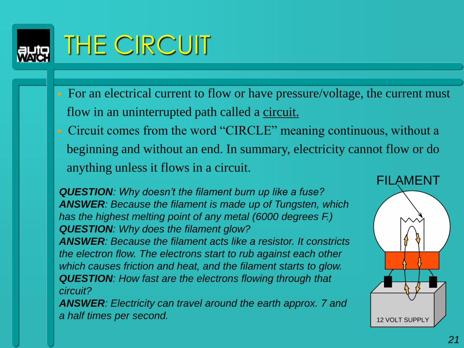
For an electrical current to flow or have pressure/voltage, the current must
flow in an uninterrupted path called a circuit.
Circuit comes from the word “CIRCLE” meaning continuous, without a
beginning and without an end. In summary, electricity cannot flow or do
anything unless it flows in a circuit.
QUESTION: Why doesn‟t the filament burn up like a fuse?
ANSWER: Because the filament is made up of Tungsten, which
has the highest melting point of any metal (6000 degrees F.)
QUESTION: Why does the filament glow?
ANSWER: Because the filament acts like a resistor. It constricts
the electron flow. The electrons start to rub against each other
which causes friction and heat, and the filament starts to glow.
QUESTION: How fast are the electrons flowing through that
circuit?
ANSWER: Electricity can travel around the earth approx. 7 and
a half times per second. 12 VOLT SUPPLY
FILAMENT
21
THE CIRCUIT
OPEN
12 VOLT SUPPLY12 VOLT SUPPLY
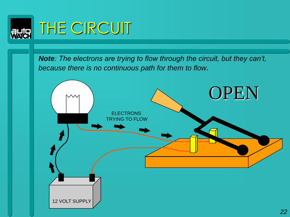
Note: The electrons are trying to flow through the circuit, but they can‟t,
because there is no continuous path for them to flow.
ELECTRONS
TRYING TO FLOW
22
THE CIRCUIT
12 VOLT SUPPLY12 VOLT SUPPLY
CLOSED
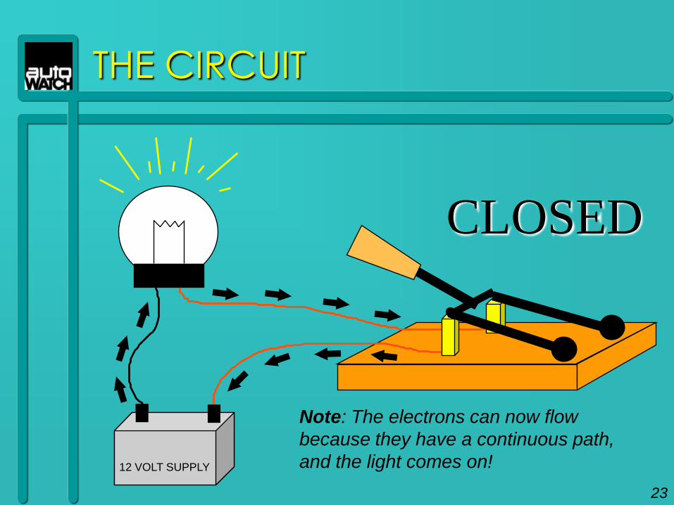
Note: The electrons can now flow
because they have a continuous path,
and the light comes on!
23
SERIES CIRCUIT
12 VOLT SUPPLY
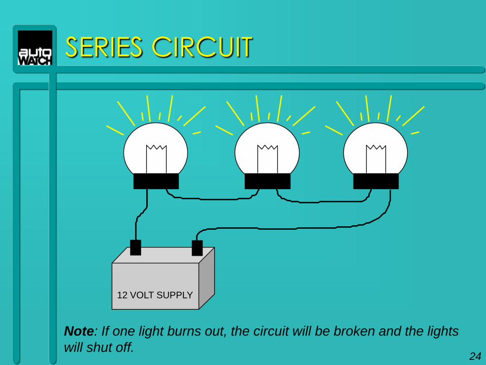
Note: If one light burns out, the circuit will be broken and the lights
will shut off.24
PARALLEL CIRCUIT
12 VOLT SUPPLY
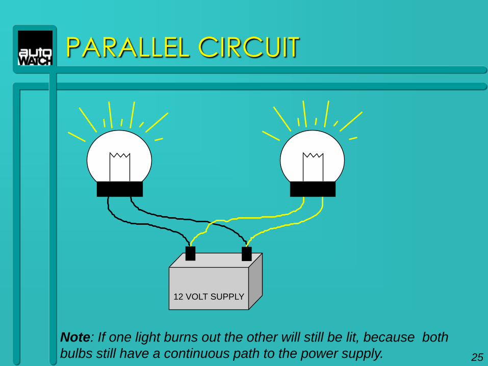
Note: If one light burns out the other will still be lit, because both
bulbs still have a continuous path to the power supply. 25

OUTPUTS
& INPUTS
26
OUTPUTS AND INPUTS
MODULEANTENNA
RECEIVER
MICROPROCESSOR
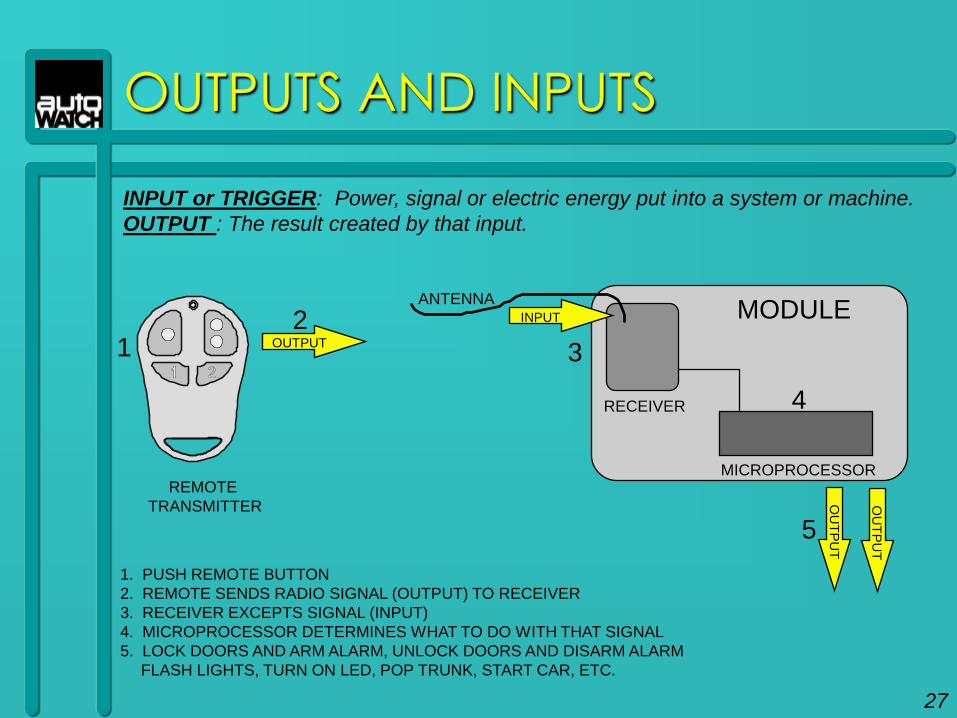
1. PUSH REMOTE BUTTON
2. REMOTE SENDS RADIO SIGNAL (OUTPUT) TO RECEIVER
3. RECEIVER EXCEPTS SIGNAL (INPUT)
4. MICROPROCESSOR DETERMINES WHAT TO DO WITH THAT SIGNAL
5. LOCK DOORS AND ARM ALARM, UNLOCK DOORS AND DISARM ALARM
FLASH LIGHTS, TURN ON LED, POP TRUNK, START CAR, ETC.
OUTPUT
INPUT
OU
TP
UT
OU
TP
UT
REMOTE
TRANSMITTER
INPUT or TRIGGER: Power, signal or electric energy put into a system or machine.
OUTPUT : The result created by that input.
12
3
4
5
27
OUTPUTS AND INPUTS
MODULE OR CONTROLLER
85
30
87a
87
86
RELAY
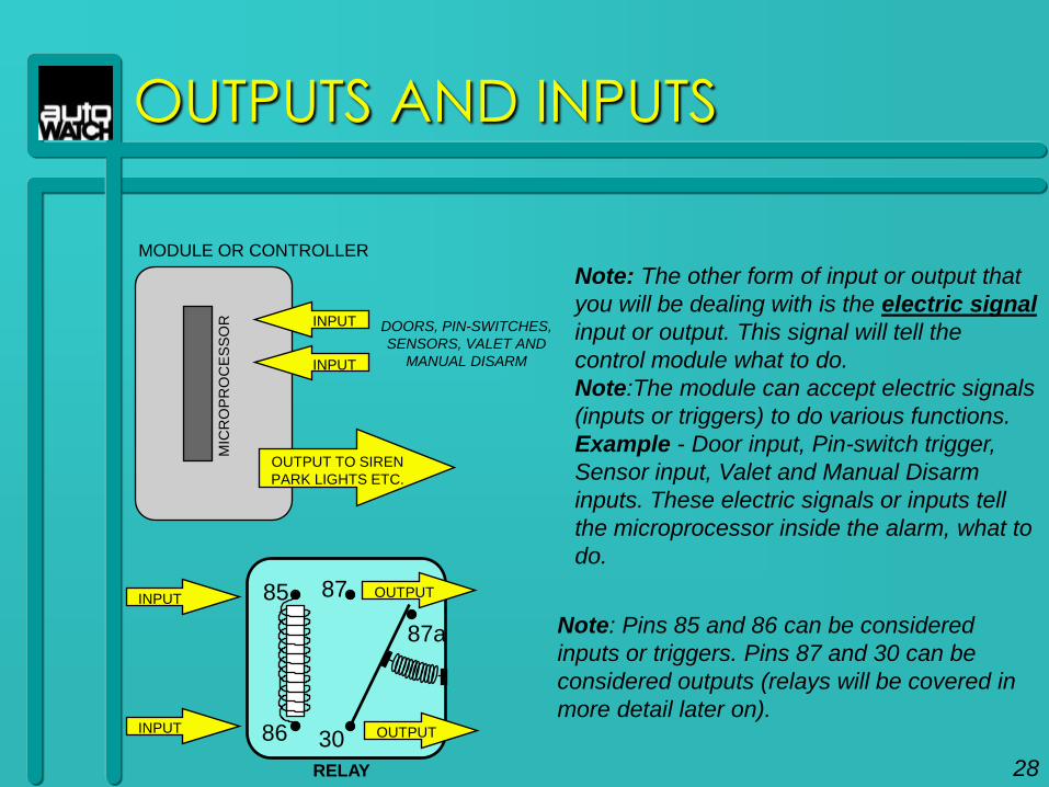
Note: Pins 85 and 86 can be considered
inputs or triggers. Pins 87 and 30 can be
considered outputs (relays will be covered in
more detail later on).
Note: The other form of input or output that
you will be dealing with is the electric signal
input or output. This signal will tell the
control module what to do.
Note:The module can accept electric signals
(inputs or triggers) to do various functions.
Example - Door input, Pin-switch trigger,
Sensor input, Valet and Manual Disarm
inputs. These electric signals or inputs tell
the microprocessor inside the alarm, what to
do.
INPUT
INPUT
OUTPUT TO SIREN
PARK LIGHTS ETC.
DOORS, PIN-SWITCHES,
SENSORS, VALET AND
MANUAL DISARM
INPUT
INPUT
OUTPUT
OUTPUT
MIC
RO
PR
OC
ES
SO
R
28
RESISTANCE
29
RESISTANCE
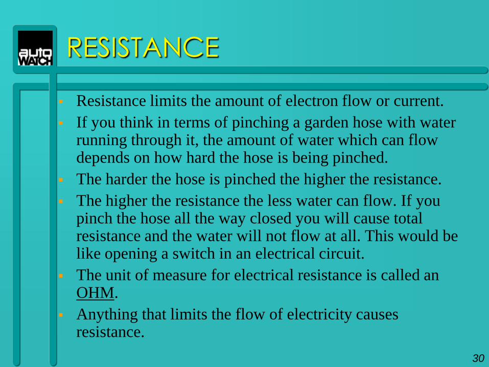
Resistance limits the amount of electron flow or current.
If you think in terms of pinching a garden hose with water running through it, the amount of water which can flow depends on how hard the hose is being pinched.
The harder the hose is pinched the higher the resistance.
The higher the resistance the less water can flow. If you pinch the hose all the way closed you will cause total resistance and the water will not flow at all. This would be like opening a switch in an electrical circuit.
The unit of measure for electrical resistance is called an OHM.
Anything that limits the flow of electricity causes resistance.
30
RESISTANCE / CONNECTIONS
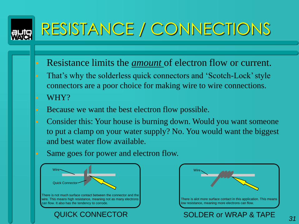
Resistance limits the amount of electron flow or current.
That‟s why the solderless quick connectors and „Scotch-Lock‟ style
connectors are a poor choice for making wire to wire connections.
WHY?
Because we want the best electron flow possible.
Consider this: Your house is burning down. Would you want someone
to put a clamp on your water supply? No. You would want the biggest
and best water flow available.
Same goes for power and electron flow.
QUICK CONNECTOR
There is not much surface contact between the connector and the
wire. This means high resistance, meaning not as many electrons
can flow. It also has the tendency to corrode.
Quick Connector
Wire
SOLDER or WRAP & TAPE
There is alot more surface contact in this application. This means
low resistance, meaning more electrons can flow.
Wire
31
RESISTORS
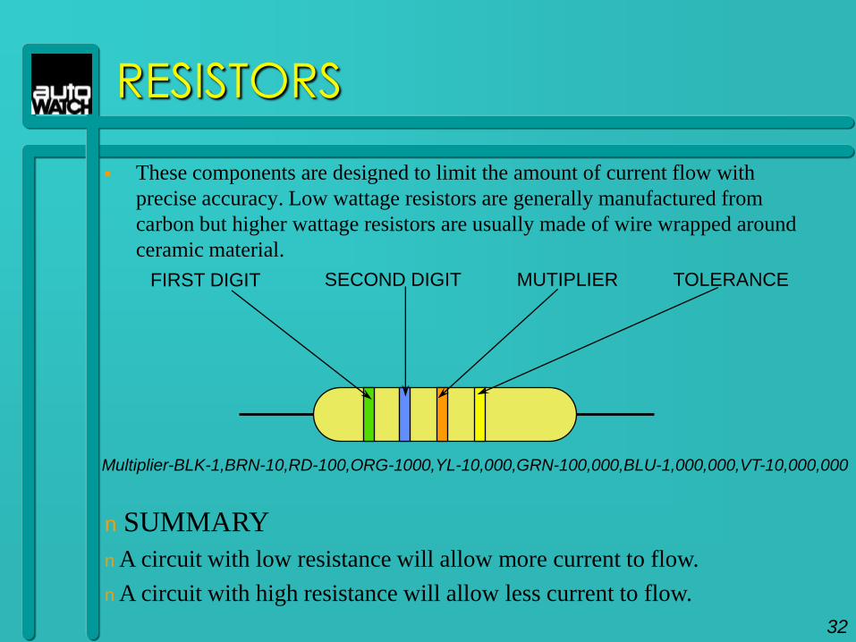
These components are designed to limit the amount of current flow with
precise accuracy. Low wattage resistors are generally manufactured from
carbon but higher wattage resistors are usually made of wire wrapped around
ceramic material.
n SUMMARY
n A circuit with low resistance will allow more current to flow.
n A circuit with high resistance will allow less current to flow.
32
FIRST DIGIT SECOND DIGIT MUTIPLIER TOLERANCE
Multiplier-BLK-1,BRN-10,RD-100,ORG-1000,YL-10,000,GRN-100,000,BLU-1,000,000,VT-10,000,000
RESISTORS
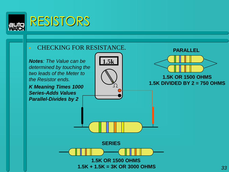
CHECKING FOR RESISTANCE.
1.5kNotes: The Value can be
determined by touching the
two leads of the Meter to
the Resistor ends.
K Meaning Times 1000
Series-Adds Values
Parallel-Divides by 2
PARALLEL
1.5K OR 1500 OHMS
1.5K DIVIDED BY 2 = 750 OHMS
1.5K OR 1500 OHMS
1.5K + 1.5K = 3K OR 3000 OHMS
SERIES
33
EXAMPLE
L
U
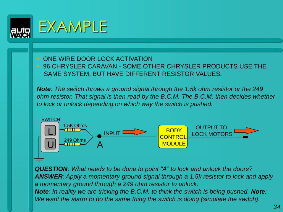
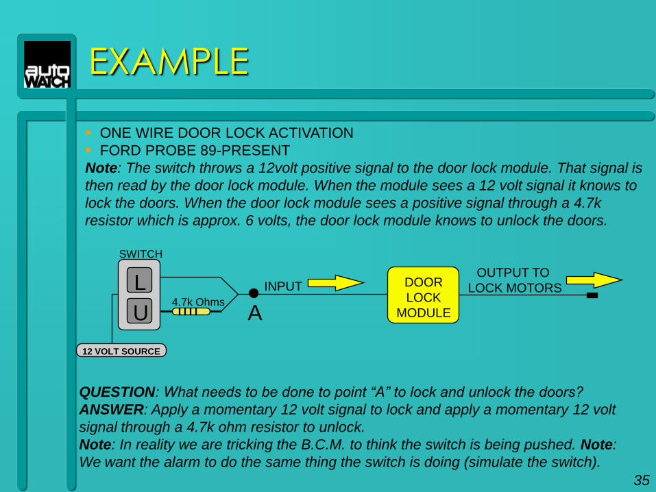
ONE WIRE DOOR LOCK ACTIVATION
96 CHRYSLER CARAVAN - SOME OTHER CHRYSLER PRODUCTS USE THE
SAME SYSTEM, BUT HAVE DIFFERENT RESISTOR VALUES.
Note: The switch throws a ground signal through the 1.5k ohm resistor or the 249
ohm resistor. That signal is then read by the B.C.M. The B.C.M. then decides whether
to lock or unlock depending on which way the switch is pushed.
1.5K Ohms
249 Ohms
BODY
CONTROL
MODULE
INPUTOUTPUT TO
LOCK MOTORS
A
QUESTION: What needs to be done to point “A” to lock and unlock the doors?
ANSWER: Apply a momentary ground signal through a 1.5k resistor to lock and apply
a momentary ground through a 249 ohm resistor to unlock.
Note: In reality we are tricking the B.C.M. to think the switch is being pushed. Note:
We want the alarm to do the same thing the switch is doing (simulate the switch).
SWITCH
34
L
U4.7k Ohms
DOOR
LOCK
MODULE
INPUTOUTPUT TO
LOCK MOTORS
A
QUESTION: What needs to be done to point “A” to lock and unlock the doors?
ANSWER: Apply a momentary 12 volt signal to lock and apply a momentary 12 volt
signal through a 4.7k ohm resistor to unlock.
Note: In reality we are tricking the B.C.M. to think the switch is being pushed. Note:
We want the alarm to do the same thing the switch is doing (simulate the switch).
SWITCH
12 VOLT SOURCE
ONE WIRE DOOR LOCK ACTIVATION
FORD PROBE 89-PRESENT
Note: The switch throws a 12volt positive signal to the door lock module. That signal is
then read by the door lock module. When the module sees a 12 volt signal it knows to
lock the doors. When the door lock module sees a positive signal through a 4.7k
resistor which is approx. 6 volts, the door lock module knows to unlock the doors.
35
EXAMPLE

THE DIODE
36
DIODES
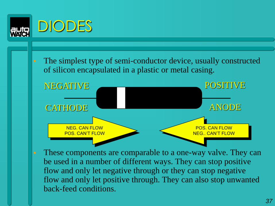
The simplest type of semi-conductor device, usually constructed of silicon encapsulated in a plastic or metal casing.
These components are comparable to a one-way valve. They can be used in a number of different ways. They can stop positive flow and only let negative through or they can stop negative flow and only let positive through. They can also stop unwanted back-feed conditions.
NEGATIVE
CATHODE
POSITIVE
ANODE
NEG. CAN FLOW
POS. CAN’T FLOW
POS. CAN FLOW
NEG.. CAN’T FLOW
37
EXAMPLE
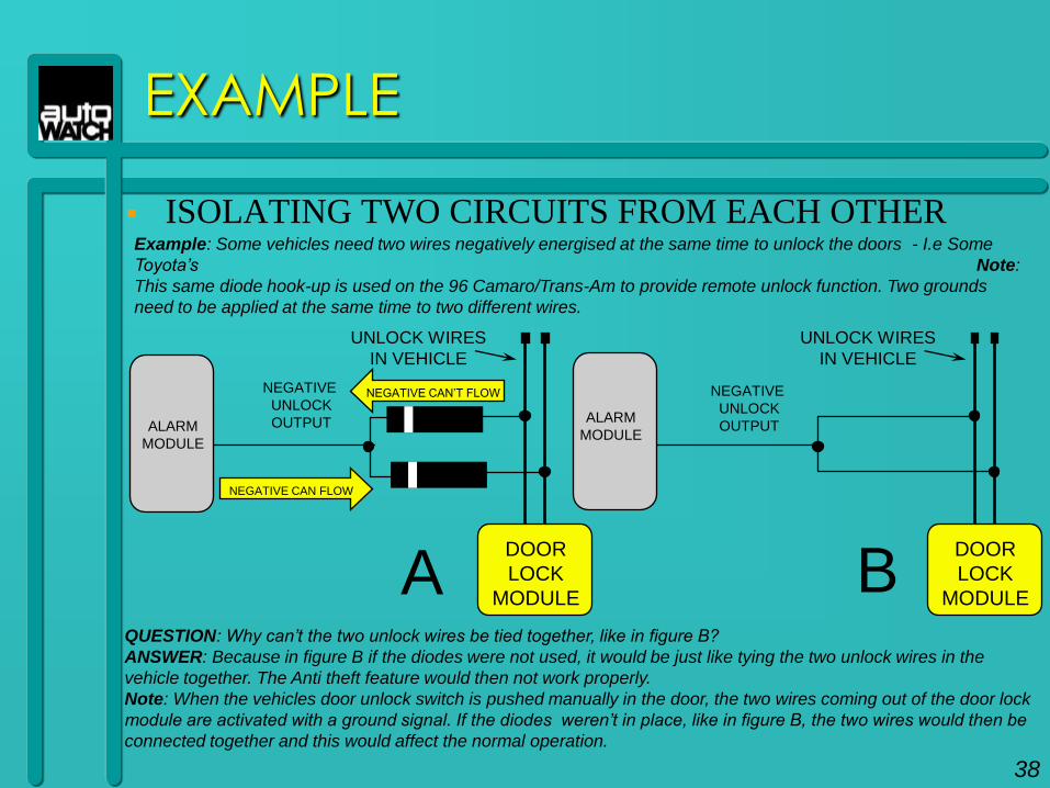
ISOLATING TWO CIRCUITS FROM EACH OTHER
QUESTION: Why can‟t the two unlock wires be tied together, like in figure B?
ANSWER: Because in figure B if the diodes were not used, it would be just like tying the two unlock wires in the
vehicle together. The Anti theft feature would then not work properly.
Note: When the vehicles door unlock switch is pushed manually in the door, the two wires coming out of the door lock
module are activated with a ground signal. If the diodes weren‟t in place, like in figure B, the two wires would then be
connected together and this would affect the normal operation.
Example: Some vehicles need two wires negatively energised at the same time to unlock the doors - I.e Some
Toyota‟s Note:
This same diode hook-up is used on the 96 Camaro/Trans-Am to provide remote unlock function. Two grounds
need to be applied at the same time to two different wires.
ALARM
MODULE
NEGATIVE
UNLOCK
OUTPUT
UNLOCK WIRES
IN VEHICLE
DOOR
LOCK
MODULE
NEGATIVE
UNLOCK
OUTPUT
UNLOCK WIRES
IN VEHICLE
DOOR
LOCK
MODULEA B
NEGATIVE CAN’T FLOW
NEGATIVE CAN FLOW
38
ALARM
MODULE
EXAMPLE
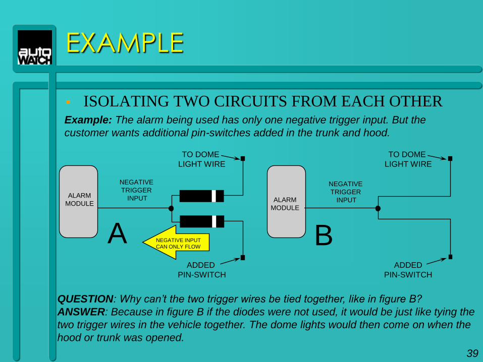
ISOLATING TWO CIRCUITS FROM EACH OTHER
QUESTION: Why can‟t the two trigger wires be tied together, like in figure B?
ANSWER: Because in figure B if the diodes were not used, it would be just like tying the
two trigger wires in the vehicle together. The dome lights would then come on when the
hood or trunk was opened.
Example: The alarm being used has only one negative trigger input. But the
customer wants additional pin-switches added in the trunk and hood.
NEGATIVE
TRIGGER
INPUT
NEGATIVE INPUT
CAN ONLY FLOWA B
TO DOME
LIGHT WIRE
ADDED
PIN-SWITCH
NEGATIVE
TRIGGER
INPUT
TO DOME
LIGHT WIRE
ADDED
PIN-SWITCH
39
ALARM
MODULE
ALARM
MODULE
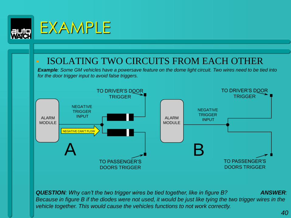
EXAMPLE
ISOLATING TWO CIRCUITS FROM EACH OTHER
QUESTION: Why can‟t the two trigger wires be tied together, like in figure B? ANSWER:
Because in figure B if the diodes were not used, it would be just like tying the two trigger wires in the
vehicle together. This would cause the vehicles functions to not work correctly.
Example: Some GM vehicles have a powersave feature on the dome light circuit. Two wires need to be tied into
for the door trigger input to avoid false triggers.
NEGATIVE
TRIGGER
INPUT
A B
TO DRIVER’S DOOR
TRIGGER
TO PASSENGER’S
DOORS TRIGGER
NEGATIVE
TRIGGER
INPUT
TO DRIVER’S DOOR
TRIGGER
TO PASSENGER’S
DOORS TRIGGER
NEGATIVE CAN’T FLOW
40
ALARM
MODULE
ALARM
MODULE
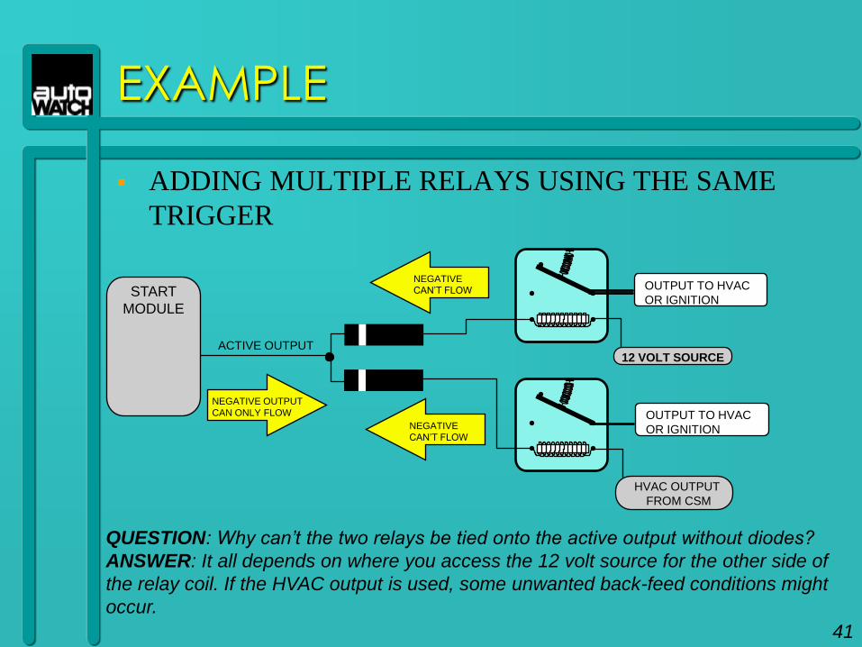
EXAMPLE
ADDING MULTIPLE RELAYS USING THE SAME
TRIGGER
ACTIVE OUTPUT
NEGATIVE OUTPUT
CAN ONLY FLOW
OUTPUT TO HVAC
OR IGNITION
OUTPUT TO HVAC
OR IGNITION
NEGATIVE
CAN’T FLOW
NEGATIVE
CAN’T FLOW
QUESTION: Why can‟t the two relays be tied onto the active output without diodes?
ANSWER: It all depends on where you access the 12 volt source for the other side of
the relay coil. If the HVAC output is used, some unwanted back-feed conditions might
occur.
12 VOLT SOURCE
HVAC OUTPUT
FROM CSM
41
START
MODULE
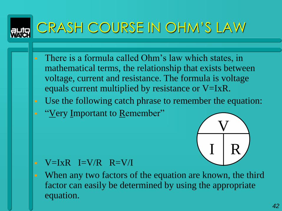
CRASH COURSE IN OHM’S LAW
There is a formula called Ohm‟s law which states, in mathematical terms, the relationship that exists between voltage, current and resistance. The formula is voltage equals current multiplied by resistance or V=IxR.
Use the following catch phrase to remember the equation:
“Very Important to Remember”
V=IxR I=V/R R=V/I
When any two factors of the equation are known, the third factor can easily be determined by using the appropriate equation.
V
I R
42
ELECTRIC
MOTORS
43
ELECTRICITY & MAGNETISM
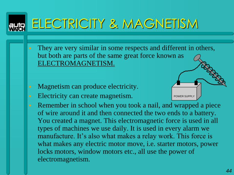
They are very similar in some respects and different in others, but both are parts of the same great force known as ELECTROMAGNETISM.
Magnetism can produce electricity.
Electricity can create magnetism.
Remember in school when you took a nail, and wrapped a piece of wire around it and then connected the two ends to a battery. You created a magnet. This electromagnetic force is used in all types of machines we use daily. It is used in every alarm we manufacture. It‟s also what makes a relay work. This force is what makes any electric motor move, i.e. starter motors, power locks motors, window motors etc., all use the power of electromagnetism.
POWER SUPPLY
44
ELECTRIC MOTORS
The electric motor uses some of the principles we
have covered so far. The motor converts electricity
and electromagnetism into a useful power source.
It is used in numerous applications in the
automobile. Anything considered a power option
is operated by some type of motor. There are
basically three different types of motors used.
Circular, Two-way and One-way.
45
ELECTRIC MOTORS: CIRCULAR
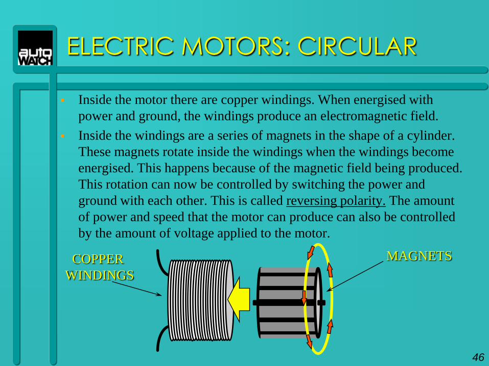
Inside the motor there are copper windings. When energised with
power and ground, the windings produce an electromagnetic field.
Inside the windings are a series of magnets in the shape of a cylinder.
These magnets rotate inside the windings when the windings become
energised. This happens because of the magnetic field being produced.
This rotation can now be controlled by switching the power and
ground with each other. This is called reversing polarity. The amount
of power and speed that the motor can produce can also be controlled
by the amount of voltage applied to the motor.
MAGNETSCOPPER
WINDINGS
46
ELECTRIC MOTORS: CIRCULAR
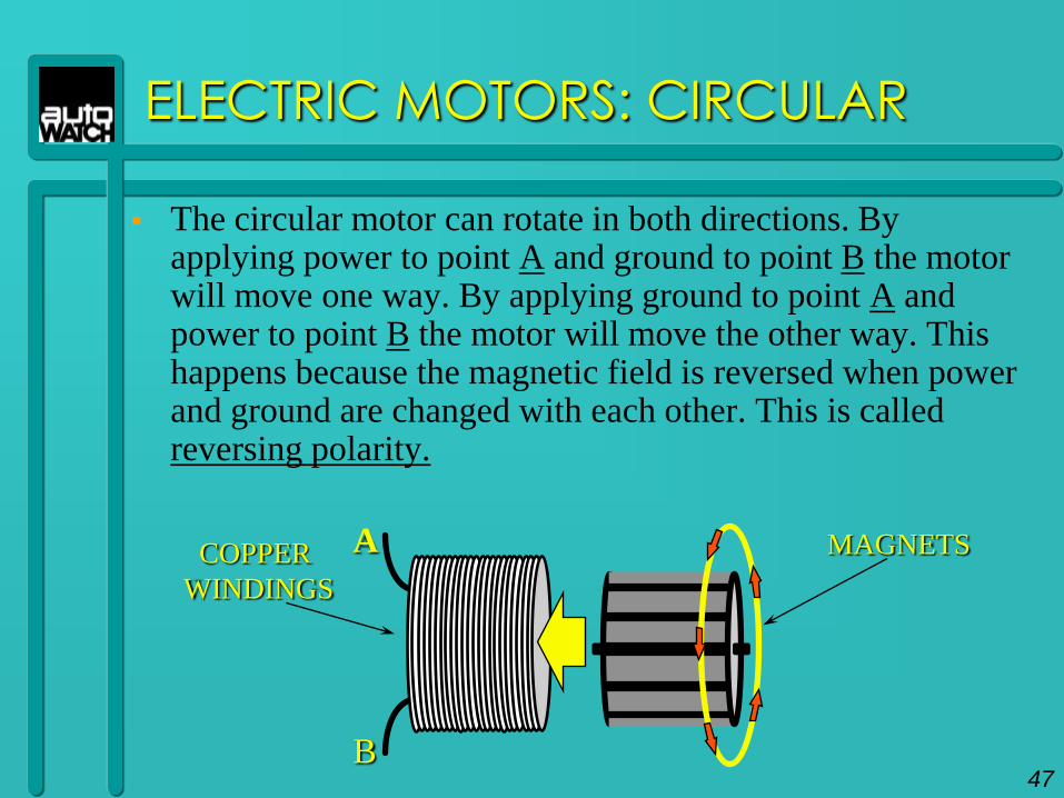
The circular motor can rotate in both directions. By applying power to point A and ground to point B the motor will move one way. By applying ground to point A and power to point B the motor will move the other way. This happens because the magnetic field is reversed when power and ground are changed with each other. This is called reversing polarity.
MAGNETSCOPPER
WINDINGS
A
B47
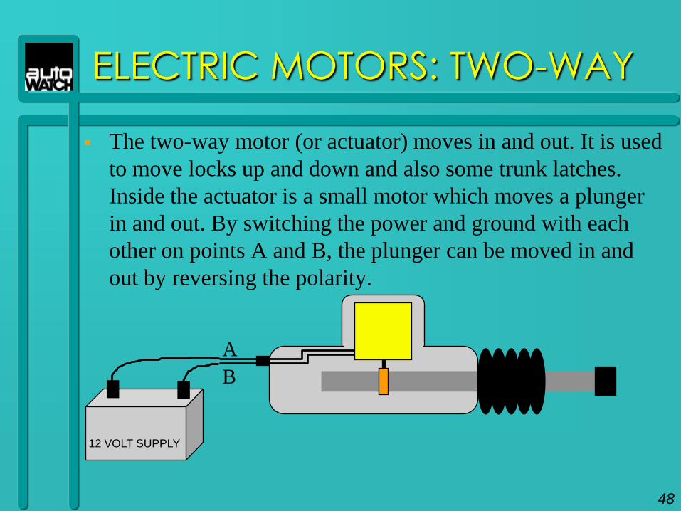
ELECTRIC MOTORS: TWO-WAY
The two-way motor (or actuator) moves in and out. It is used
to move locks up and down and also some trunk latches.
Inside the actuator is a small motor which moves a plunger
in and out. By switching the power and ground with each
other on points A and B, the plunger can be moved in and
out by reversing the polarity.
A
B
12 VOLT SUPPLY
48
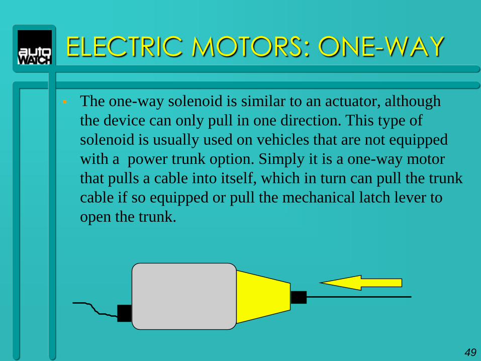
ELECTRIC MOTORS: ONE-WAY
The one-way solenoid is similar to an actuator, although
the device can only pull in one direction. This type of
solenoid is usually used on vehicles that are not equipped
with a power trunk option. Simply it is a one-way motor
that pulls a cable into itself, which in turn can pull the trunk
cable if so equipped or pull the mechanical latch lever to
open the trunk.
49

INSTALLATION
BASICS
50
INSTALLATION BASICS
What makes a good installer?
Read all instructions first.
Make proper connections: ideally centre splice-wrap, solder and tape.
Not recommended: T-taps or Scotch-locks.
Know how to use test equipment.
Use a good quality insulation tape (like 3M).
Test for circuits prior to installation. Know how you will be routing the wires together to certain key locations.
Verify good ground source.
Pre-plan the installation.
Prep the module completely before doing the installation.
51
INSTALLATION BASICS
Organise, group and wrap wire harness.
Check for module mounting location.
Shock location - Vehicle bodywork or Thick wire loom near steering column.
Siren - Keep away from excess heat and water splash.
If the firewall has to be drilled through, use sealing compound or silicone to seal the hole.
Keep your own notes
Neatness counts.
If the customer goes back to the dealer with a problem, you want the installation to be as neat as possible, otherwise you may get the blame for that problem.
52

53
THE RELAY
THE RELAY
An electromechanical device that uses a coil (electro) to move a switch (mechanical).
THE COIL
The Coil is the first step to understanding the relay. The coil can be energised using a small amount of power. A typical automotive type relay requires a coil current of 0.150 amps or 150 milliamps to energise. The coil contacts (pins) are numbered 85 and 86 on the relay. It is important to know that pin 85 is the negative coil contact. Although the coil will still energise if the connections are reversed the correct polarity should be observed. Some relays have an internal diode to prevent inductive spikes upon relay turn off.
54
THE RELAY
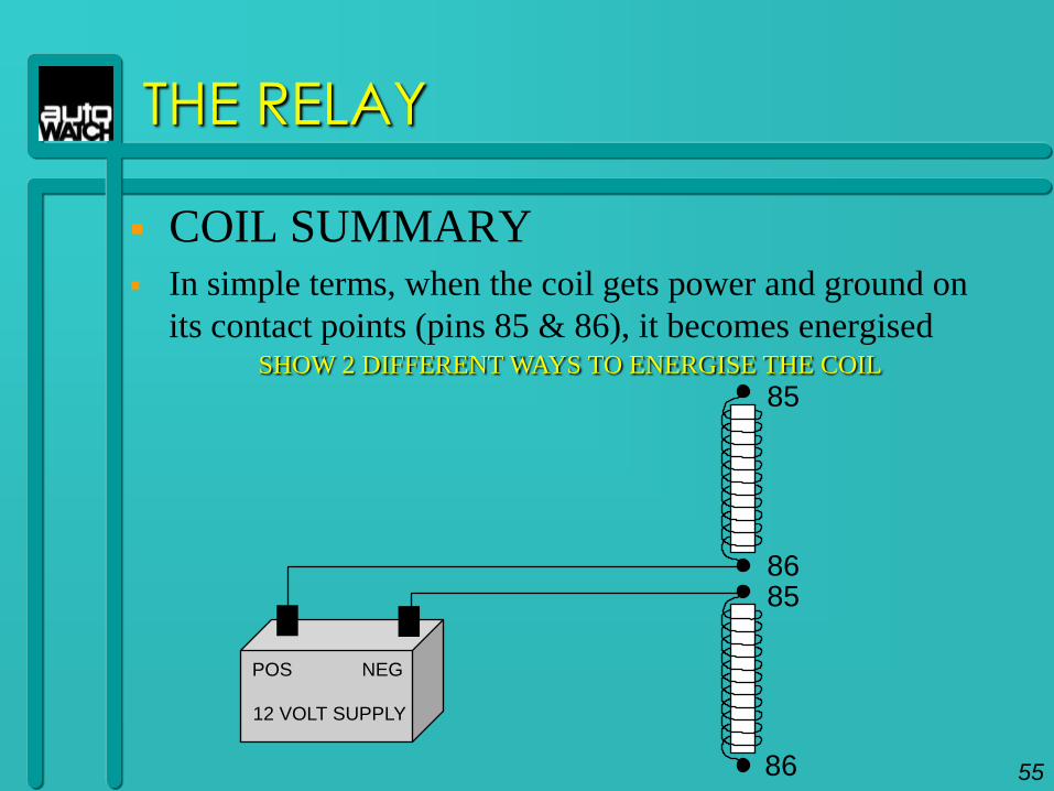
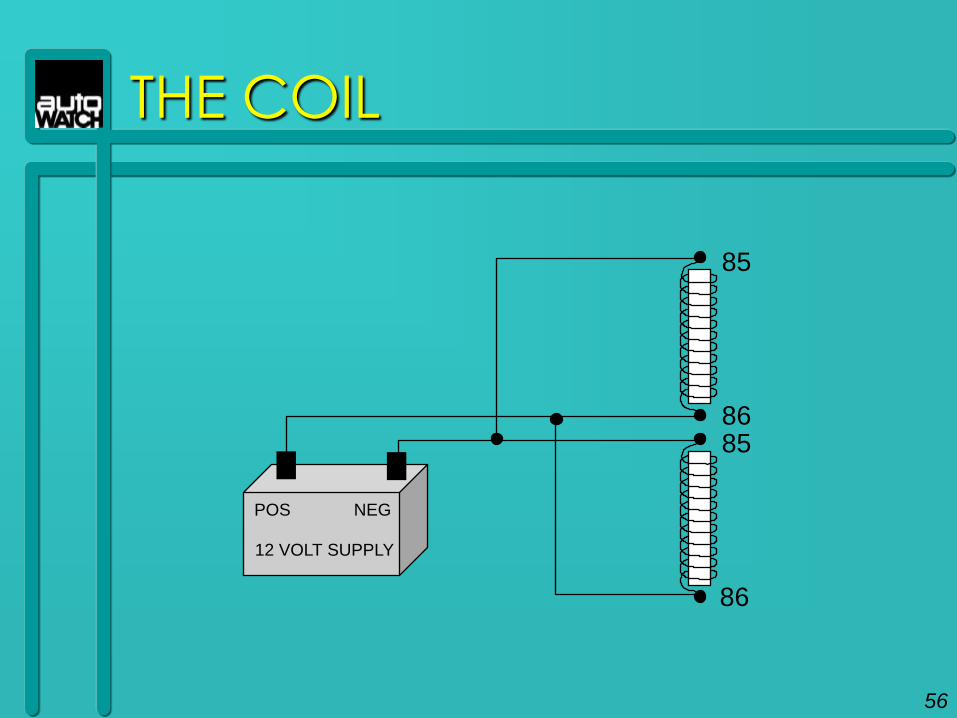
COIL SUMMARY In simple terms, when the coil gets power and ground on
its contact points (pins 85 & 86), it becomes energisedSHOW 2 DIFFERENT WAYS TO ENERGISE THE COIL
85
8685
86
12 VOLT SUPPLY
POS NEG
55
THE COIL
85
8685
86
12 VOLT SUPPLY
POS NEG
56
THE RELAY
INTERNAL SWITCHING OF THE RELAY
Besides the coil, there is also a switch inside the relay. The contact
points (pins) are numbered 30 common (C), 87a normally closed
(N.C.) and 87 normally open (N.O.). These terms are explained as
follows.
30 COMMON
Common means that pin 30 has something in common with the
other two contact points. When the coil of the relay is energised
pin 30 pivots between 87a and 87. When the relay is at rest 30 is in
contact with 87a. When the coil is energised the magnetic force
pulls the lever over. Now 30 is in contact with 87. When power or
ground is taken away from the coil, it loses its magnetic force and
the spring pulls the lever back to the rest position.
57
THE RELAY
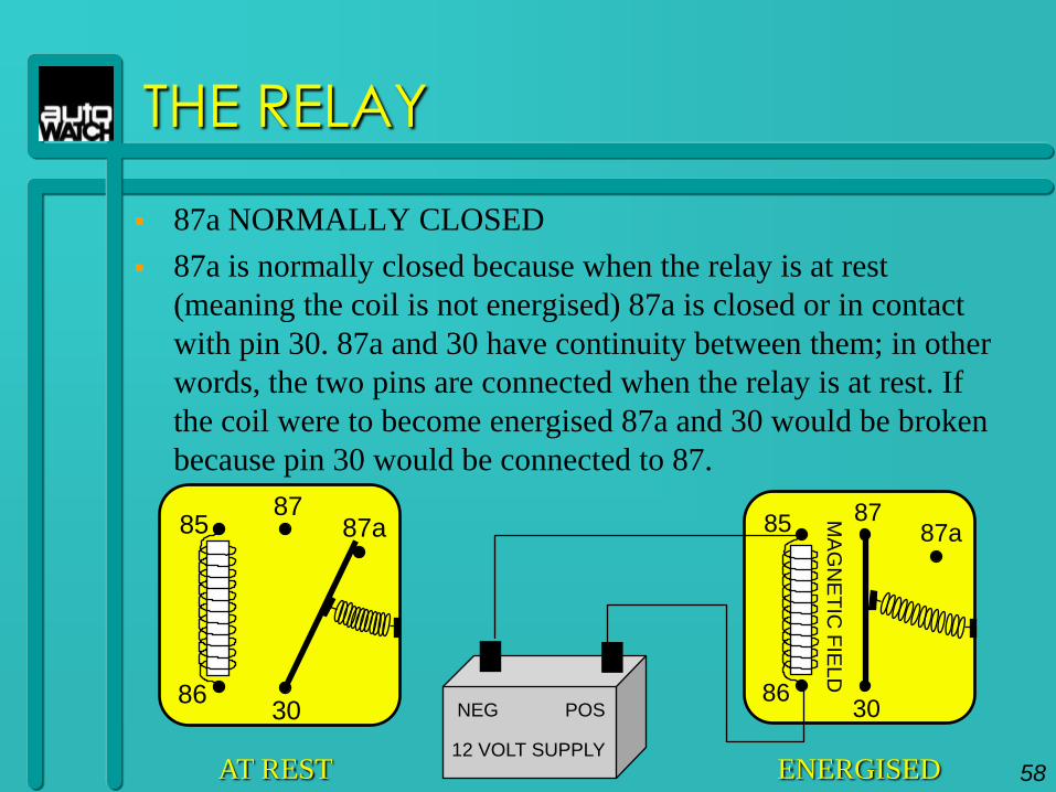
87a NORMALLY CLOSED
87a is normally closed because when the relay is at rest
(meaning the coil is not energised) 87a is closed or in contact
with pin 30. 87a and 30 have continuity between them; in other
words, the two pins are connected when the relay is at rest. If
the coil were to become energised 87a and 30 would be broken
because pin 30 would be connected to 87.
85
30
87a87
86
AT REST
85
30
87a87
86
ENERGISED
MA
GN
ET
IC F
IEL
D
12 VOLT SUPPLY
POSNEG
58
THE RELAY
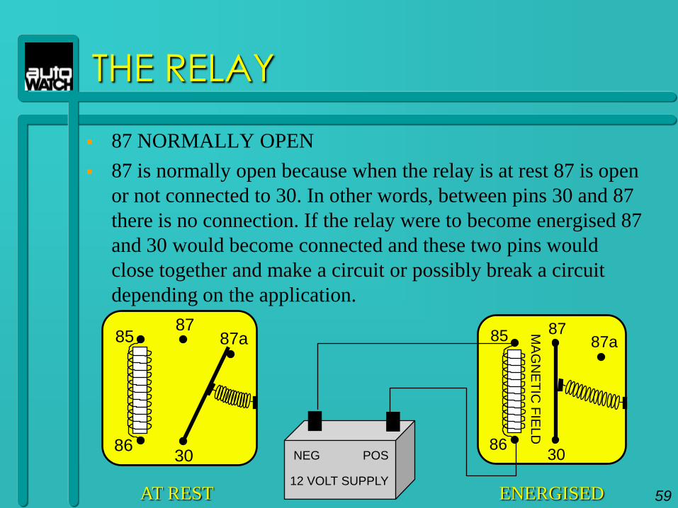
87 NORMALLY OPEN
87 is normally open because when the relay is at rest 87 is open
or not connected to 30. In other words, between pins 30 and 87
there is no connection. If the relay were to become energised 87
and 30 would become connected and these two pins would
close together and make a circuit or possibly break a circuit
depending on the application.
85
30
87a87
86
AT REST
85
30
87a87
86
ENERGISED
MA
GN
ET
IC F
IEL
D
12 VOLT SUPPLY
POSNEG
59
THE RELAY
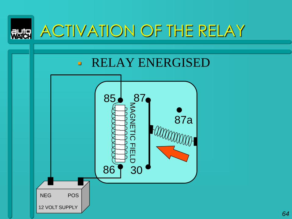
SUMMARY
When the relay is at rest 30 is connected to 87a.
When the coil is energised, it becomes a magnet
and pulls the lever over and connects contact
points 30 and 87. In other words the relay is an
electromagnetic switch. It is triggered by
electricity. The magnetic force overpowers the
spring and closes the contacts 30 to 87, for as long
as the coil of the relay is energised.
60
RELAY NOTES
NOTES: When using relays in alarm applications an easy rule applies.
85 -- NEGATIVE TRIGGER (coil feed)
86 -- POSITIVE TRIGGER (coil feed)
30 -- OUTPUT, MOTOR SIDE OR COMMON
87a - SWITCH SIDE OR NORMALLY CLOSED
87 -- POLARITY OR NORMALLY OPEN (determines output)
Whatever is being used to trigger the relay be it positive or negative, the other side of the coil must be the opposite, so that the coil can be energised.
Pin 87 determines the polarity of the output 30. If 87 is at ground, when the relay is energised, 30 will then become grounded. If 87 is at +12 volts when the relay is energised 30 will then become +12 volts.
61
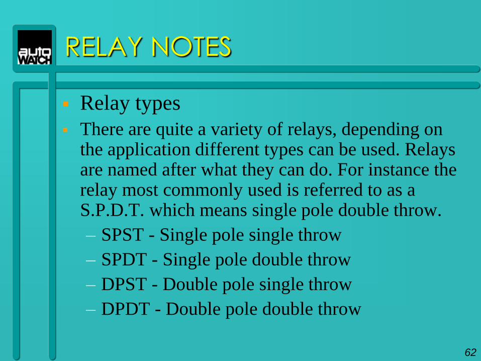
Relay types
There are quite a variety of relays, depending on the application different types can be used. Relays are named after what they can do. For instance the relay most commonly used is referred to as a S.P.D.T. which means single pole double throw.
– SPST - Single pole single throw
– SPDT - Single pole double throw
– DPST - Double pole single throw
– DPDT - Double pole double throw
RELAY NOTES
62
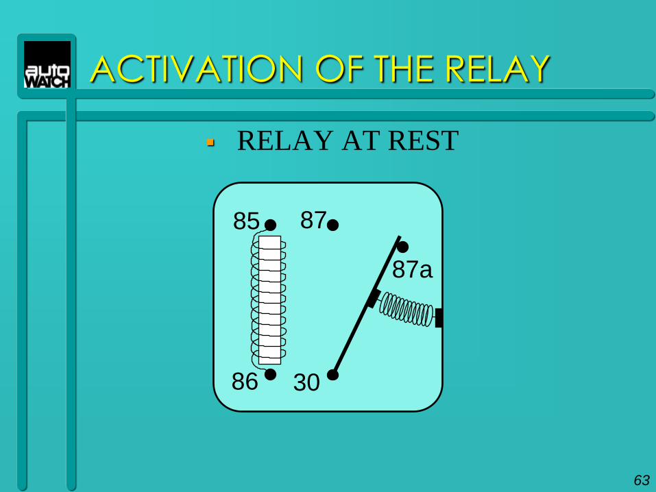
ACTIVATION OF THE RELAY
RELAY AT REST
85
30
87a
87
86
63
85
30
87a
87
86
ACTIVATION OF THE RELAY
RELAY ENERGISED
MA
GN
ET
IC F
IELD
12 VOLT SUPPLY
POSNEG
64
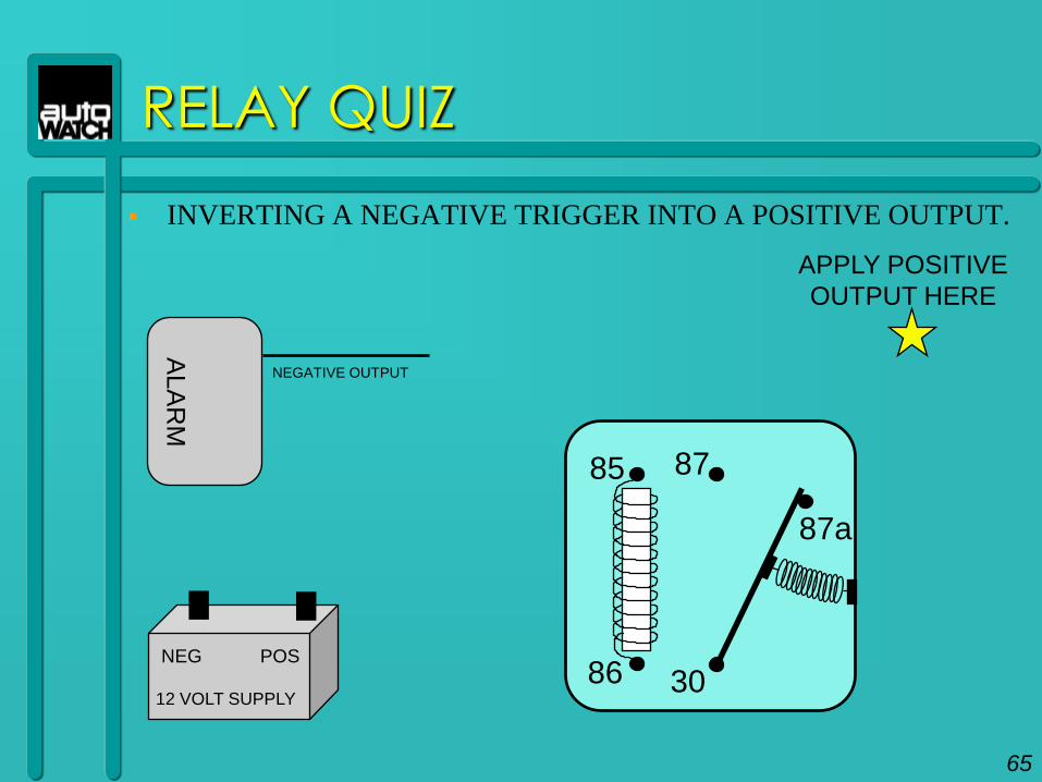
RELAY QUIZ
INVERTING A NEGATIVE TRIGGER INTO A POSITIVE OUTPUT.
85
30
87a
87
86
ALA
RM
NEGATIVE OUTPUT
APPLY POSITIVE
OUTPUT HERE
65
12 VOLT SUPPLY
POSNEG
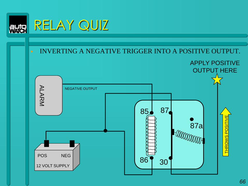
RELAY QUIZ
INVERTING A NEGATIVE TRIGGER INTO A POSITIVE OUTPUT.
85
30
87a
87
86
ALA
RM
NEGATIVE OUTPUT
APPLY POSITIVE
OUTPUT HERE
TH
RO
WS
PO
SIT
IVE
66
12 VOLT SUPPLY
NEGPOS
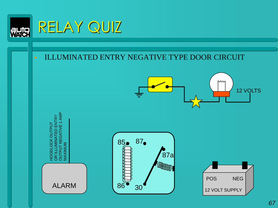
RELAY QUIZ
ILLUMINATED ENTRY NEGATIVE TYPE DOOR CIRCUIT
85
30
87a
87
86ALARM
HO
OD
LO
CK
OU
TP
UT
OR
ILLU
MIN
AT
ED
EN
TR
Y
OU
TP
UT
NE
GA
TIV
E 1
AM
P
MA
XIM
UM
12 VOLTS
67
12 VOLT SUPPLY
NEGPOS
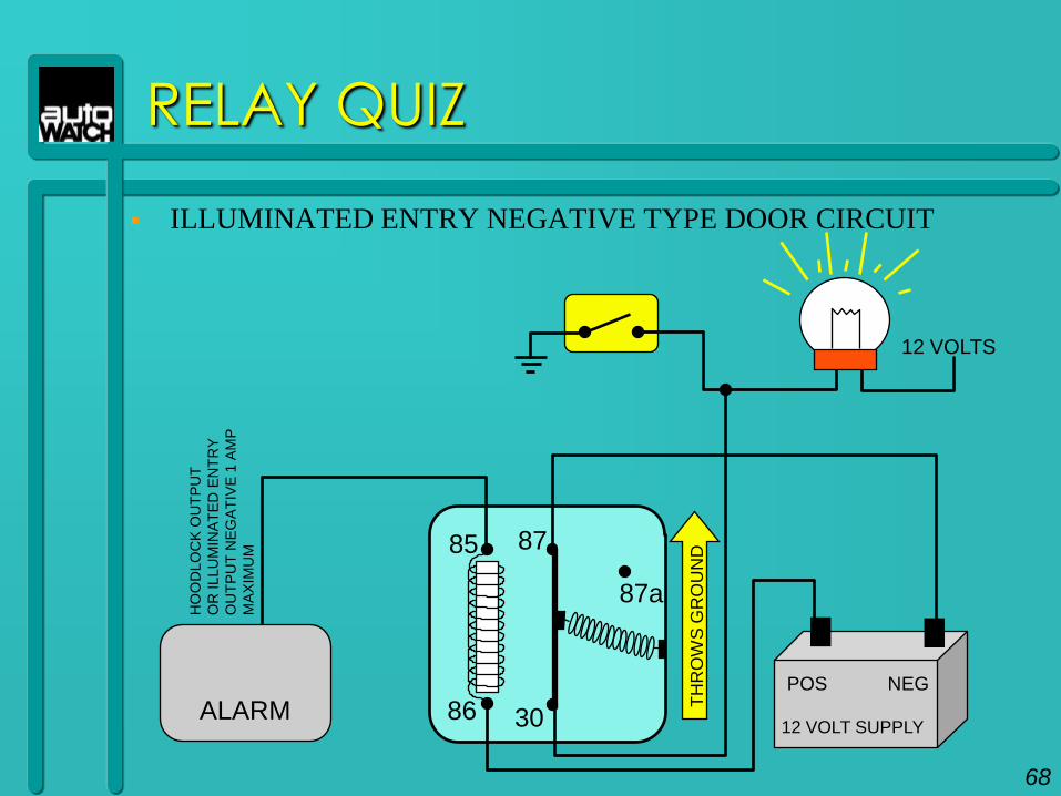
RELAY QUIZ
ILLUMINATED ENTRY NEGATIVE TYPE DOOR CIRCUIT
85
30
87a
87
86ALARM
HO
OD
LO
CK
OU
TP
UT
OR
ILLU
MIN
AT
ED
EN
TR
Y
OU
TP
UT
NE
GA
TIV
E 1
AM
P
MA
XIM
UM
12 VOLTS
TH
RO
WS
GR
OU
ND
68
12 VOLT SUPPLY
NEGPOS
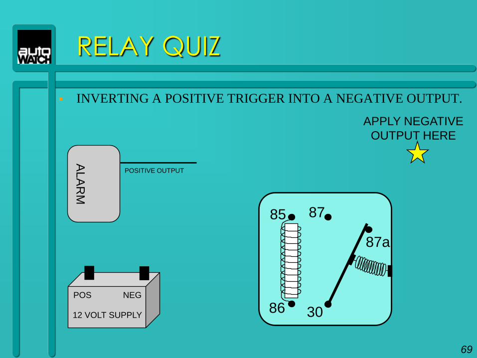
RELAY QUIZ
INVERTING A POSITIVE TRIGGER INTO A NEGATIVE OUTPUT.
85
30
87a
87
86
ALA
RM
POSITIVE OUTPUT
APPLY NEGATIVE
OUTPUT HERE
12 VOLT SUPPLY
POS NEG
69
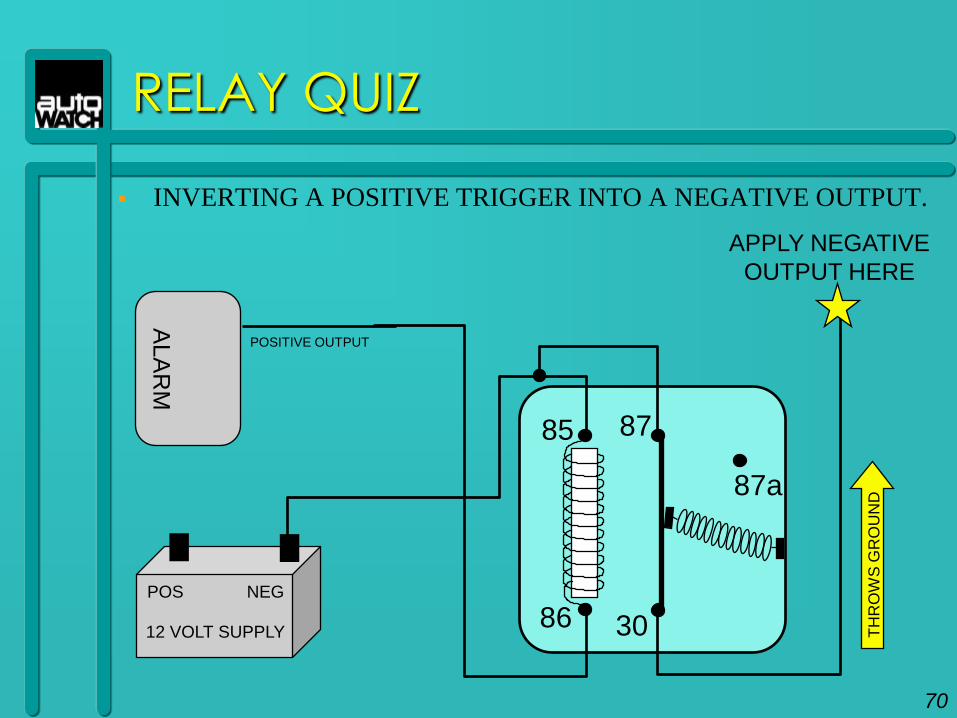
RELAY QUIZ
INVERTING A POSITIVE TRIGGER INTO A NEGATIVE OUTPUT.
85
30
87a
87
86
ALA
RM
POSITIVE OUTPUT
APPLY NEGATIVE
OUTPUT HERE
TH
RO
WS
GR
OU
ND
70
12 VOLT SUPPLY
POS NEG
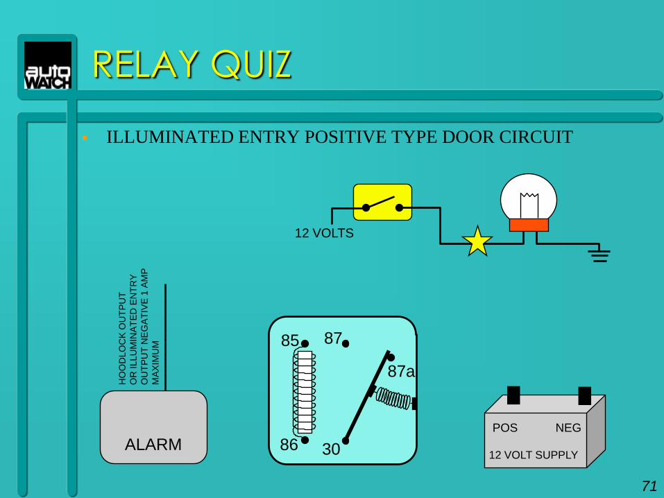
RELAY QUIZ
ILLUMINATED ENTRY POSITIVE TYPE DOOR CIRCUIT
85
30
87a
87
86ALARM
HO
OD
LO
CK
OU
TP
UT
OR
ILLU
MIN
AT
ED
EN
TR
Y
OU
TP
UT
NE
GA
TIV
E 1
AM
P
MA
XIM
UM
12 VOLTS
71
12 VOLT SUPPLY
NEGPOS
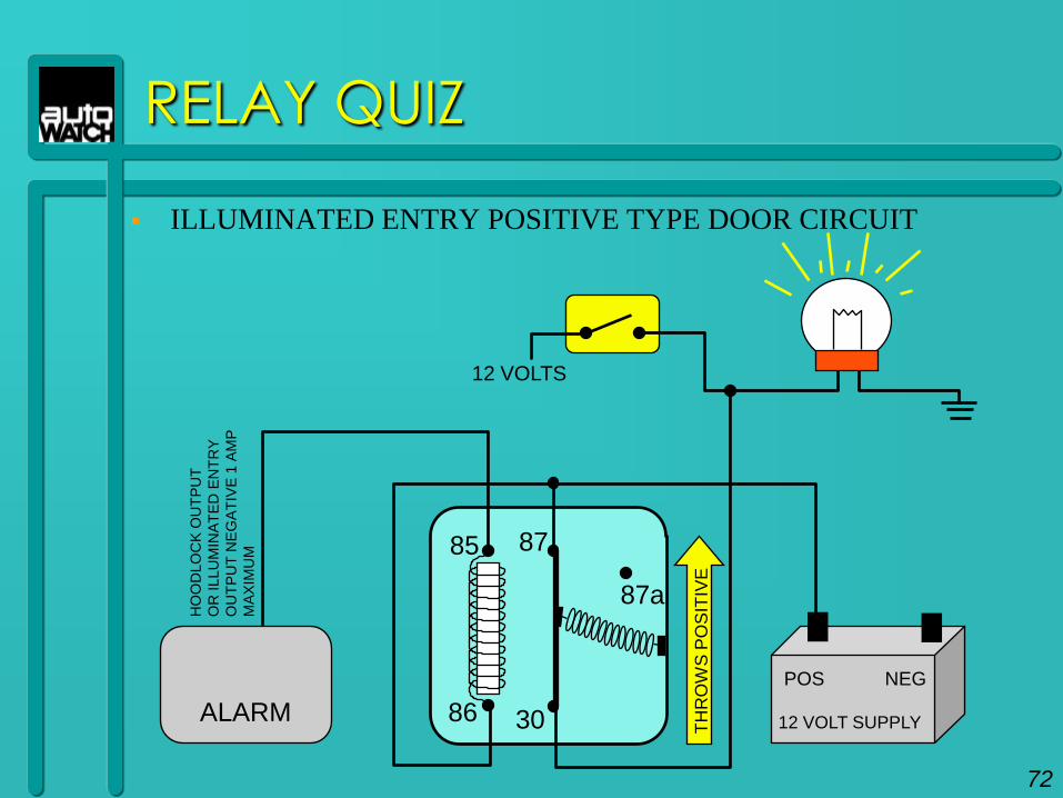
RELAY QUIZ
ILLUMINATED ENTRY POSITIVE TYPE DOOR CIRCUIT
85
30
87a
87
86ALARM
HO
OD
LO
CK
OU
TP
UT
OR
ILLU
MIN
AT
ED
EN
TR
Y
OU
TP
UT
NE
GA
TIV
E 1
AM
P
MA
XIM
UM
12 VOLTS
TH
RO
WS
PO
SIT
IVE
72
12 VOLT SUPPLY
NEGPOS
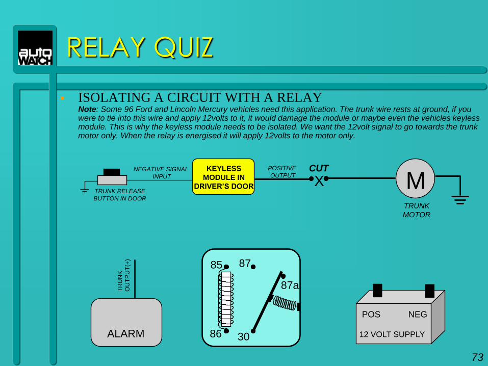
RELAY QUIZ
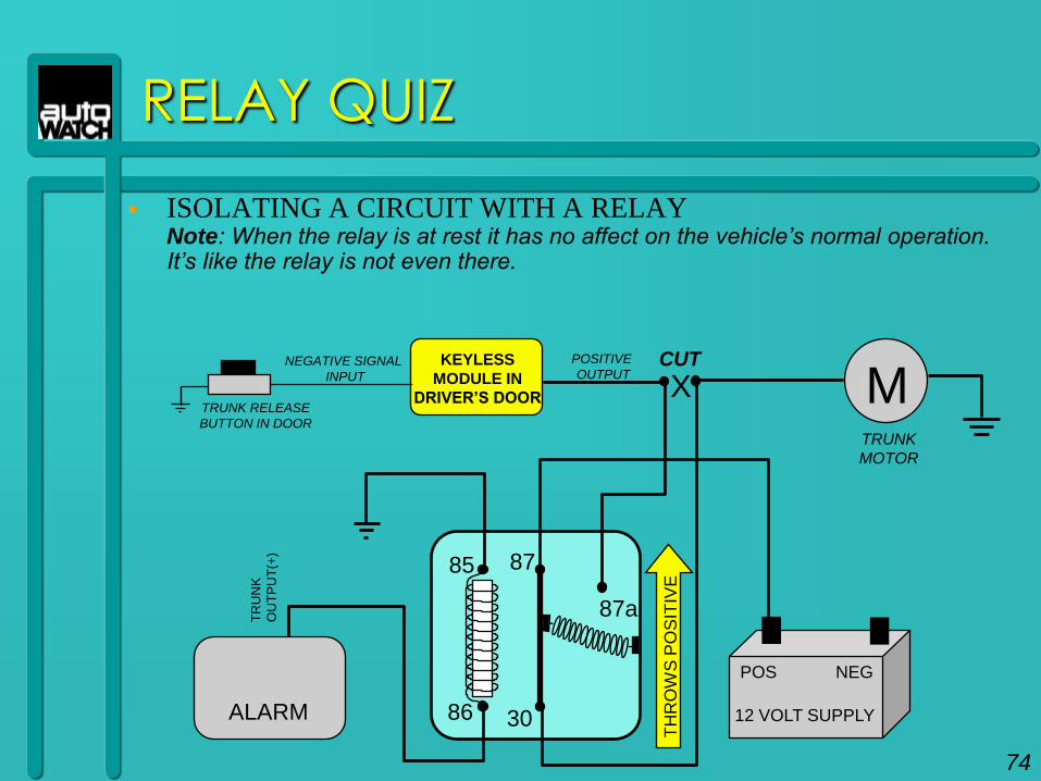
ISOLATING A CIRCUIT WITH A RELAY Note: Some 96 Ford and Lincoln Mercury vehicles need this application. The trunk wire rests at ground, if you were to tie into this wire and apply 12volts to it, it would damage the module or maybe even the vehicles keyless module. This is why the keyless module needs to be isolated. We want the 12volt signal to go towards the trunk motor only. When the relay is energised it will apply 12volts to the motor only.
85
30
87a
87
86ALARM
TR
UN
K
OU
TP
UT
(+)
KEYLESS
MODULE IN
DRIVER’S DOORTRUNK RELEASE
BUTTON IN DOOR
MCUT
X
TRUNK
MOTOR
NEGATIVE SIGNAL
INPUT
POSITIVE
OUTPUT
73
12 VOLT SUPPLY
NEGPOS
RELAY QUIZ
ISOLATING A CIRCUIT WITH A RELAY Note: When the relay is at rest it has no affect on the vehicle‟s normal operation. It‟s like the relay is not even there.
85
30
87a
87
86ALARM
TR
UN
K
OU
TP
UT
(+)
12 VOLT SUPPLY
POS NEG
KEYLESS
MODULE IN
DRIVER’S DOORTRUNK RELEASE
BUTTON IN DOOR
MCUT
X
TRUNK
MOTOR
NEGATIVE SIGNAL
INPUT
POSITIVE
OUTPUT
TH
RO
WS
PO
SIT
IVE
74
RELAY QUIZ
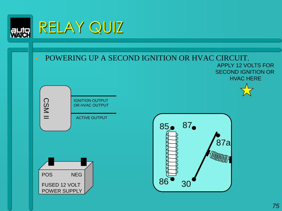
POWERING UP A SECOND IGNITION OR HVAC CIRCUIT.
85
30
87a
87
86
CS
M II
IGNITION OUTPUT
OR HVAC OUTPUT
APPLY 12 VOLTS FOR
SECOND IGNITION OR
HVAC HERE
FUSED 12 VOLT
POWER SUPPLY
POS NEG
ACTIVE OUTPUT
75
RELAY QUIZ
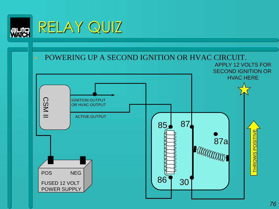
POWERING UP A SECOND IGNITION OR HVAC CIRCUIT.
85
30
87a
87
86
CS
M II
IGNITION OUTPUT
OR HVAC OUTPUT
ACTIVE OUTPUT
APPLY 12 VOLTS FOR
SECOND IGNITION OR
HVAC HERE
TH
RO
WS
PO
SIT
IVE
76
FUSED 12 VOLT
POWER SUPPLY
POS NEG
77
DOOR LOCKS
Note: The examples in the following slides show
control switches for left-hand drive vehicles.
DOOR LOCKS
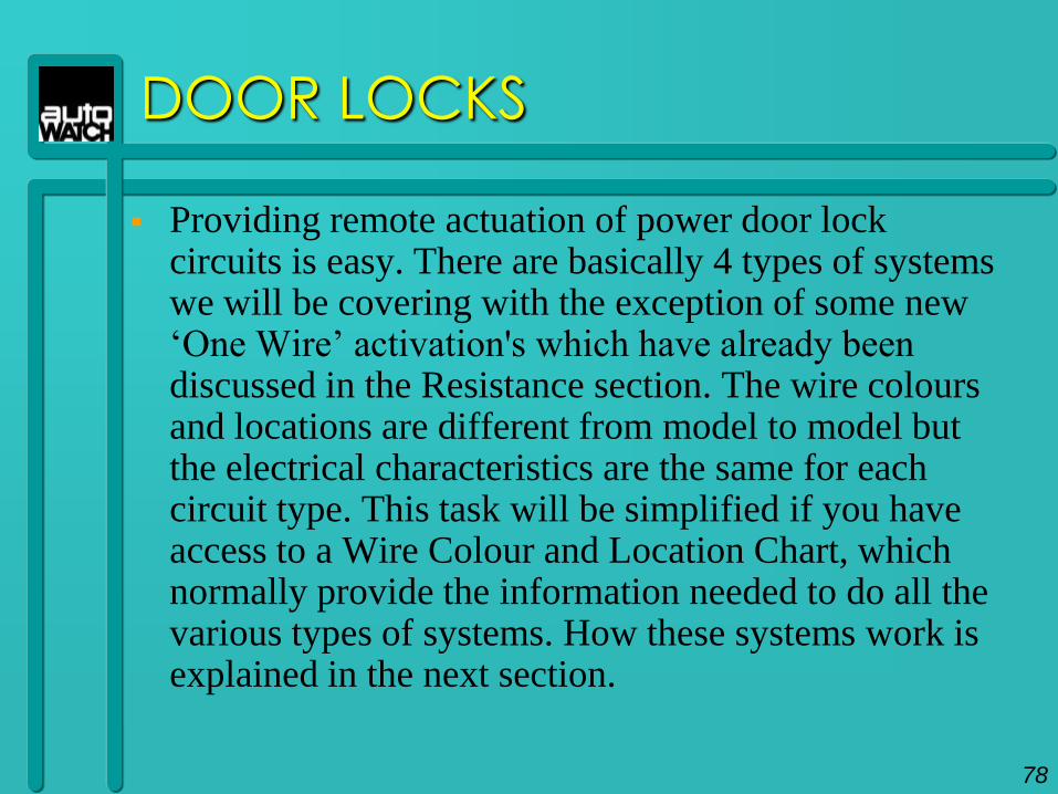
Providing remote actuation of power door lock circuits is easy. There are basically 4 types of systems we will be covering with the exception of some new „One Wire‟ activation's which have already been discussed in the Resistance section. The wire colours and locations are different from model to model but the electrical characteristics are the same for each circuit type. This task will be simplified if you have access to a Wire Colour and Location Chart, which normally provide the information needed to do all the various types of systems. How these systems work is explained in the next section.
78
85 30
87a
8786
L
85 30
87a
8786
12V
INSIDE LEFT
DOOR
L
U
MASTERSWITCH
12V
INSIDE RIGHT
DOOR
L
U
FUSED 12 VOLT
SOURCE
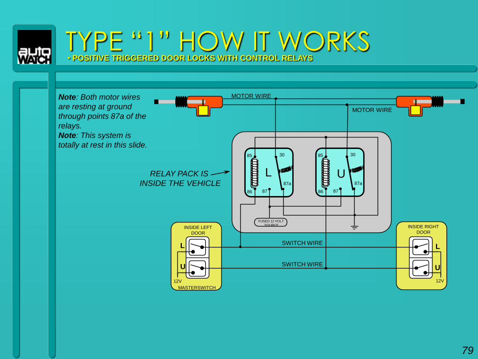
TYPE “1” HOW IT WORKS• POSITIVE TRIGGERED DOOR LOCKS WITH CONTROL RELAYS
U
SWITCH WIRE
SWITCH WIRE
MOTOR WIRE
MOTOR WIRE
Note: Both motor wires
are resting at ground
through points 87a of the
relays.
Note: This system is
totally at rest in this slide.
RELAY PACK IS
INSIDE THE VEHICLE
79
85 30
87a
8786
L
85 30
87a
8786
12V
INSIDE LEFT
DOOR
L
U
MASTER SWITCH
12V
INSIDE RIGHT
DOOR
L
U
FUSED 12 VOLT
SOURCE
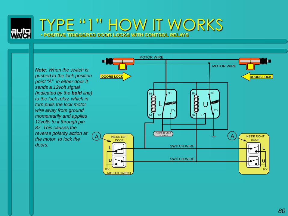
Note: When the switch is
pushed to the lock position
point “A” in either door It
sends a 12volt signal
(indicated by the bold line)
to the lock relay, which in
turn pulls the lock motor
wire away from ground
momentarily and applies
12volts to it through pin
87. This causes the
reverse polarity action at
the motor to lock the
doors.
TYPE “1” HOW IT WORKS• POSITIVE TRIGGERED DOOR LOCKS WITH CONTROL RELAYS
A
U
A
SWITCH WIRE
SWITCH WIRE
MOTOR WIRE
MOTOR WIRE
DOORS LOCK DOORS LOCK
80
85 30
87a
8786
U
85 30
87a
8786
L
12V
INSIDE LEFT
DOOR
L
U
MASTER SWITCH
12V
INSIDE RIGHT
DOOR
L
U
FUSED 12 VOLT
SOURCE
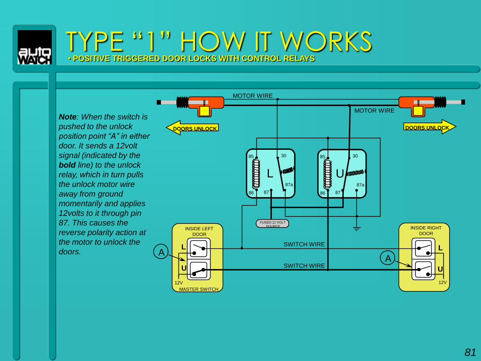
Note: When the switch is
pushed to the unlock
position point “A” in either
door. It sends a 12volt
signal (indicated by the
bold line) to the unlock
relay, which in turn pulls
the unlock motor wire
away from ground
momentarily and applies
12volts to it through pin
87. This causes the
reverse polarity action at
the motor to unlock the
doors.
TYPE “1” HOW IT WORKS• POSITIVE TRIGGERED DOOR LOCKS WITH CONTROL RELAYS
AA
SWITCH WIRE
SWITCH WIRE
MOTOR WIRE
MOTOR WIRE
DOORS UNLOCK DOORS UNLOCK
81
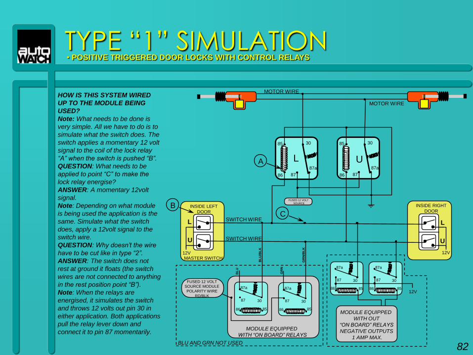
TYPE “1” SIMULATION• POSITIVE TRIGGERED DOOR LOCKS WITH CONTROL RELAYS
HOW IS THIS SYSTEM WIRED
UP TO THE MODULE BEING
USED?
Note: What needs to be done is
very simple. All we have to do is to
simulate what the switch does. The
switch applies a momentary 12 volt
signal to the coil of the lock relay
“A” when the switch is pushed “B”.
QUESTION: What needs to be
applied to point “C” to make the
lock relay energise?
ANSWER: A momentary 12volt
signal.
Note: Depending on what module
is being used the application is the
same. Simulate what the switch
does, apply a 12volt signal to the
switch wire.
QUESTION: Why doesn‟t the wire
have to be cut like in type “2”.
ANSWER: The switch does not
rest at ground it floats (the switch
wires are not connected to anything
in the rest position point “B”).
Note: When the relays are
energised, it simulates the switch
and throws 12 volts out pin 30 in
either application. Both applications
pull the relay lever down and
connect it to pin 87 momentarily.
85 30
87a
8786
L
85 30
87a
8786
A U
MOTOR WIRE
MOTOR WIRE
12V
INSIDE RIGHT
DOOR
L
U
FUSED 12 VOLT
SOURCE
12V
INSIDE LEFT
DOOR
L
U
MASTER SWITCH
B
SWITCH WIRE
SWITCH WIRE
C
MODULE EQUIPPED
WITH “ON BOARD” RELAYS
30
87a
87
86 85
30
87a
87
86 85
30
87a
87
86 85
30
87a
87
86 8512V
MODULE EQUIPPED
WITH OUT
“ON BOARD” RELAYS
NEGATIVE OUTPUTS
1 AMP MAX.
FUSED 12 VOLT
SOURCE MODULE
POLARITY WIRE
RD/BLK
BL
U/B
LK
BL
U
GR
N/B
LK
GR
N
BLU AND GRN NOT USED82
12V
12V
INSIDE LEFT
DOOR
12V
12V
INSIDE RIGHT
DOOR
L
U
MASTER SWITCH
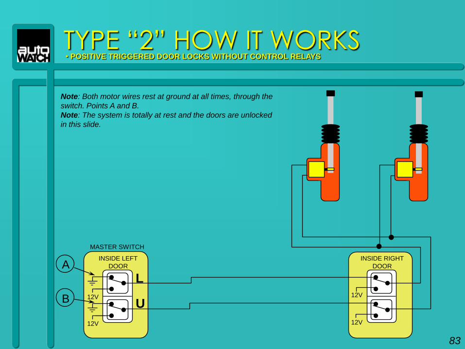
Note: Both motor wires rest at ground at all times, through the
switch. Points A and B.
Note: The system is totally at rest and the doors are unlocked
in this slide.
A
B
TYPE “2” HOW IT WORKS• POSITIVE TRIGGERED DOOR LOCKS WITHOUT CONTROL RELAYS
83
12V
12V
INSIDE LEFT
DOOR
12V
12V
INSIDE RIGHT
DOOR
L
U
MASTER SWITCH
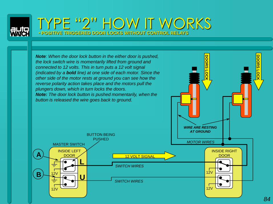
Note: When the door lock button in the either door is pushed,
the lock switch wire is momentarily lifted from ground and
connected to 12 volts. This in turn puts a 12 volt signal
(indicated by a bold line) at one side of each motor. Since the
other side of the motor rests at ground you can see how the
reverse polarity action takes place and the motors pull the
plungers down, which in turn locks the doors.
Note: The door lock button is pushed momentarily, when the
button is released the wire goes back to ground.
A
B
12 VOLT SIGNAL
WIRE ARE RESTING
AT GROUNDBUTTON BEING
PUSHED
DO
OR
S L
OC
K
DO
OR
S L
OC
K
TYPE “2” HOW IT WORKS• POSITIVE TRIGGERED DOOR LOCKS WITHOUT CONTROL RELAYS
SWITCH WIRES
SWITCH WIRES
MOTOR WIRES
84
12V
12V
INSIDE LEFT
DOOR
12V
12V
INSIDE RIGHT
DOOR
L
U
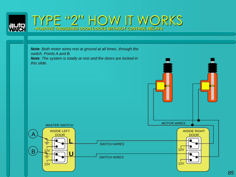
Note: Both motor wires rest at ground at all times, through the
switch. Points A and B.
Note: The system is totally at rest and the doors are locked in
this slide.
A
B
TYPE “2” HOW IT WORKS• POSITIVE TRIGGERED DOOR LOCKS WITHOUT CONTROL RELAYS
SWITCH WIRES
SWITCH WIRES
MOTOR WIRES
85
MASTER SWITCH
12V
12V
INSIDE LEFT
DOOR
12V
12V
INSIDE RIGHT
DOOR
L
U
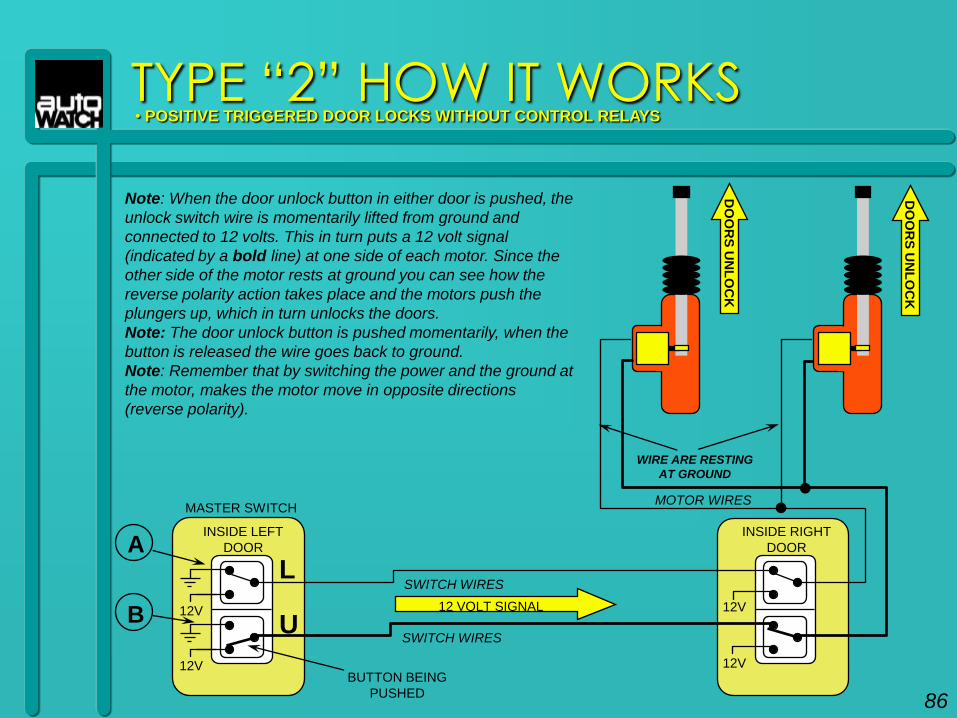
Note: When the door unlock button in either door is pushed, the
unlock switch wire is momentarily lifted from ground and
connected to 12 volts. This in turn puts a 12 volt signal
(indicated by a bold line) at one side of each motor. Since the
other side of the motor rests at ground you can see how the
reverse polarity action takes place and the motors push the
plungers up, which in turn unlocks the doors.
Note: The door unlock button is pushed momentarily, when the
button is released the wire goes back to ground.
Note: Remember that by switching the power and the ground at
the motor, makes the motor move in opposite directions
(reverse polarity).
A
B12 VOLT SIGNAL
BUTTON BEING
PUSHED
WIRE ARE RESTING
AT GROUND
DO
OR
S U
NL
OC
K
DO
OR
S U
NL
OC
K
TYPE “2” HOW IT WORKS• POSITIVE TRIGGERED DOOR LOCKS WITHOUT CONTROL RELAYS
SWITCH WIRES
SWITCH WIRES
MOTOR WIRES
86
MASTER SWITCH
12V
12V
INSIDE LEFT
DOOR
12V
12V
INSIDE RIGHT
DOOR
L
U
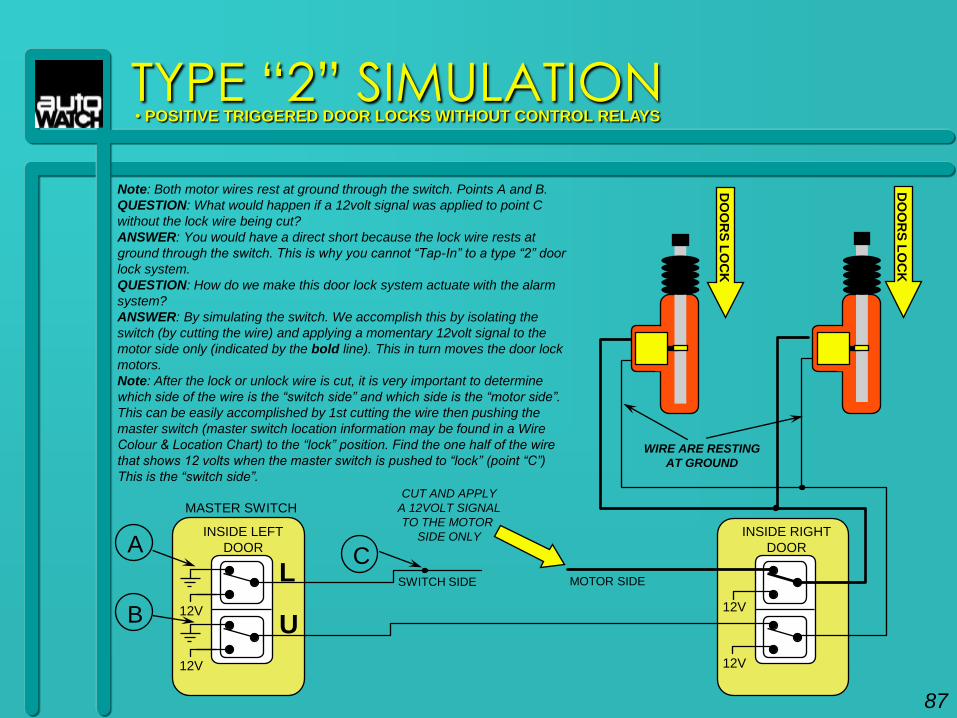
Note: Both motor wires rest at ground through the switch. Points A and B.
QUESTION: What would happen if a 12volt signal was applied to point C
without the lock wire being cut?
ANSWER: You would have a direct short because the lock wire rests at
ground through the switch. This is why you cannot “Tap-In” to a type “2” door
lock system.
QUESTION: How do we make this door lock system actuate with the alarm
system?
ANSWER: By simulating the switch. We accomplish this by isolating the
switch (by cutting the wire) and applying a momentary 12volt signal to the
motor side only (indicated by the bold line). This in turn moves the door lock
motors.
Note: After the lock or unlock wire is cut, it is very important to determine
which side of the wire is the “switch side” and which side is the “motor side”.
This can be easily accomplished by 1st cutting the wire then pushing the
master switch (master switch location information may be found in a Wire
Colour & Location Chart) to the “lock” position. Find the one half of the wire
that shows 12 volts when the master switch is pushed to “lock” (point “C”)
This is the “switch side”.
B
AC
SWITCH SIDE MOTOR SIDE
CUT AND APPLY
A 12VOLT SIGNAL
TO THE MOTOR
SIDE ONLY
DO
OR
S L
OC
K
DO
OR
S L
OC
K
TYPE “2” SIMULATION• POSITIVE TRIGGERED DOOR LOCKS WITHOUT CONTROL RELAYS
WIRE ARE RESTING
AT GROUND
87
MASTER SWITCH
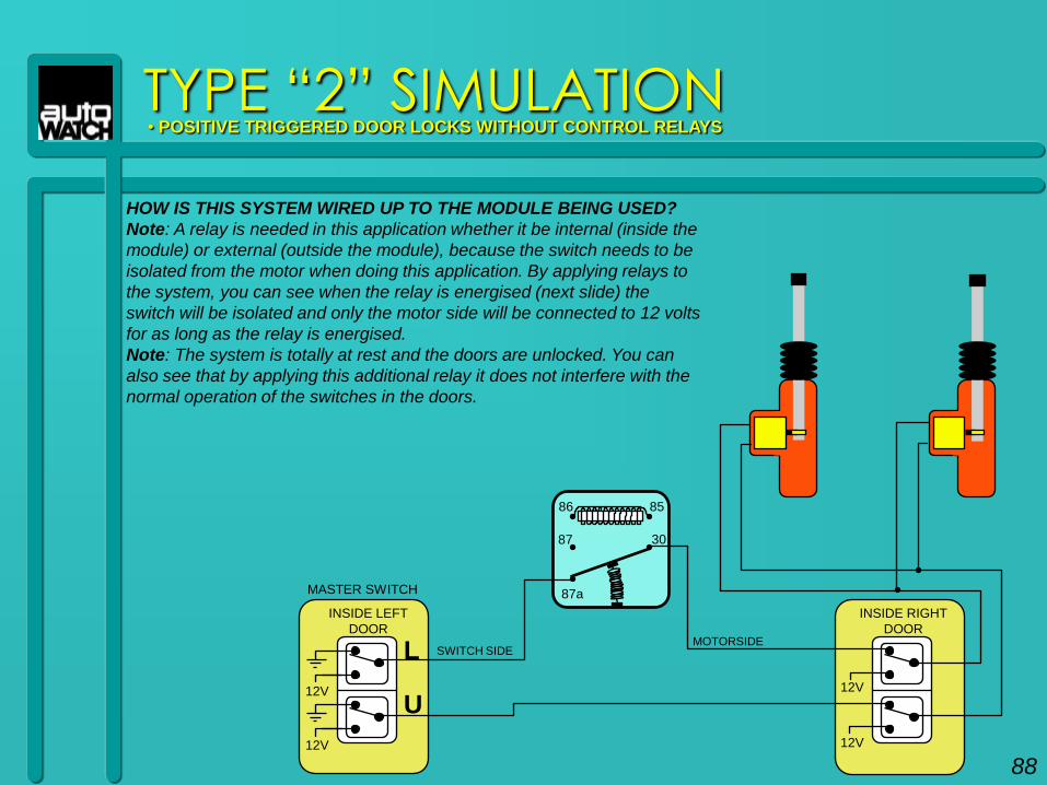
HOW IS THIS SYSTEM WIRED UP TO THE MODULE BEING USED?
Note: A relay is needed in this application whether it be internal (inside the
module) or external (outside the module), because the switch needs to be
isolated from the motor when doing this application. By applying relays to
the system, you can see when the relay is energised (next slide) the
switch will be isolated and only the motor side will be connected to 12 volts
for as long as the relay is energised.
Note: The system is totally at rest and the doors are unlocked. You can
also see that by applying this additional relay it does not interfere with the
normal operation of the switches in the doors.
12V
12V
INSIDE LEFT
DOOR
12V
12V
INSIDE RIGHT
DOOR
L
U
SWITCH SIDEMOTORSIDE
30
87a
87
86 85
TYPE “2” SIMULATION• POSITIVE TRIGGERED DOOR LOCKS WITHOUT CONTROL RELAYS
88
MASTER SWITCH
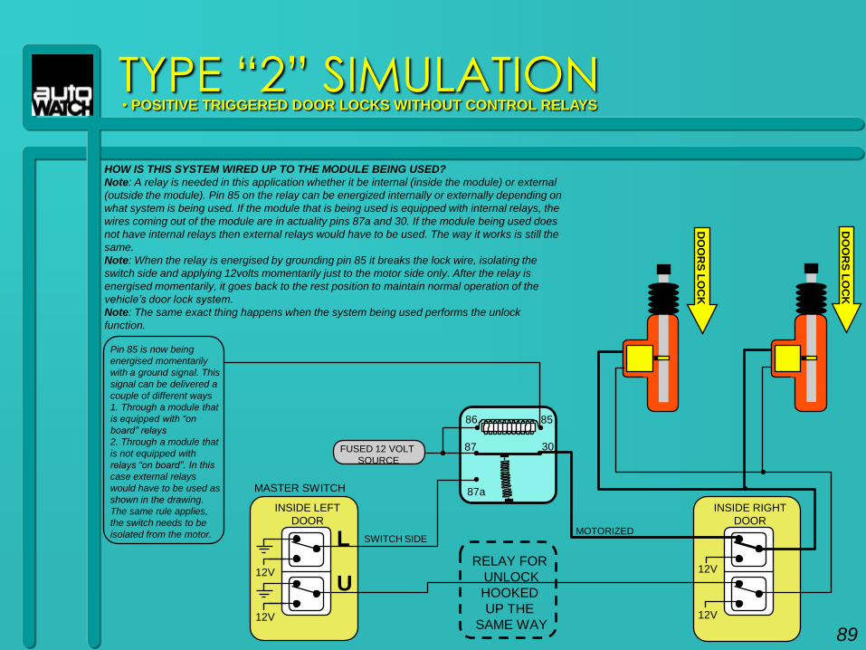
HOW IS THIS SYSTEM WIRED UP TO THE MODULE BEING USED?
Note: A relay is needed in this application whether it be internal (inside the module) or external
(outside the module). Pin 85 on the relay can be energized internally or externally depending on
what system is being used. If the module that is being used is equipped with internal relays, the
wires coming out of the module are in actuality pins 87a and 30. If the module being used does
not have internal relays then external relays would have to be used. The way it works is still the
same.
Note: When the relay is energised by grounding pin 85 it breaks the lock wire, isolating the
switch side and applying 12volts momentarily just to the motor side only. After the relay is
energised momentarily, it goes back to the rest position to maintain normal operation of the
vehicle‟s door lock system.
Note: The same exact thing happens when the system being used performs the unlock
function.
TYPE “2” SIMULATION• POSITIVE TRIGGERED DOOR LOCKS WITHOUT CONTROL RELAYS
12V
12V
INSIDE LEFT
DOOR
12V
12V
INSIDE RIGHT
DOOR
L
U
SWITCH SIDEMOTORIZED
30
87a
87
86 85
FUSED 12 VOLT
SOURCE
DO
OR
S L
OC
K
DO
OR
S L
OC
K
RELAY FOR
UNLOCK
HOOKED
UP THE
SAME WAY
Pin 85 is now being
energised momentarily
with a ground signal. This
signal can be delivered a
couple of different ways
1. Through a module that
is equipped with “on
board” relays
2. Through a module that
is not equipped with
relays “on board”. In this
case external relays
would have to be used as
shown in the drawing.
The same rule applies,
the switch needs to be
isolated from the motor.
89
MASTER SWITCH
HOW IS THIS SYSTEM WIRED UP TO THE MODULE BEING USED?
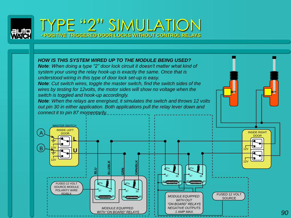
Note: When doing a type “2” door lock circuit it doesn‟t matter what kind of
system your using the relay hook-up is exactly the same. Once that is
understood wiring in this type of door lock set-up is easy.
Note: Cut switch wires, toggle the master switch, find the switch sides of the
wires by testing for 12volts, the motor sides will show no voltage when the
switch is toggled and hook-up accordingly.
Note: When the relays are energised, it simulates the switch and throws 12 volts
out pin 30 in either application. Both applications pull the relay lever down and
connect it to pin 87 momentarily.
TYPE “2” SIMULATION• POSITIVE TRIGGERED DOOR LOCKS WITHOUT CONTROL RELAYS
INSIDE RIGHT
DOOR
12V
12V
INSIDE LEFT
DOOR
L
U
MASTER SWITCH
A
B 12V
12V
MODULE EQUIPPED
WITH “ON BOARD” RELAYS
30
87a
87
86 85
30
87a
87
86 85 MODULE EQUIPPED
WITH OUT
“ON BOARD” RELAYS
NEGATIVE OUTPUTS
1 AMP MAX.
30
87a
87
86 85
30
87a
87
86 85
FUSED 12 VOLT
SOURCE
FUSED 12 VOLT
SOURCE MODULE
POLARITY WIRE
RD/BLK
BL
U/B
LK
BL
U
GR
N/B
LK
GR
N
90
RELAY PACK IS
INSIDE THE VEHICLE
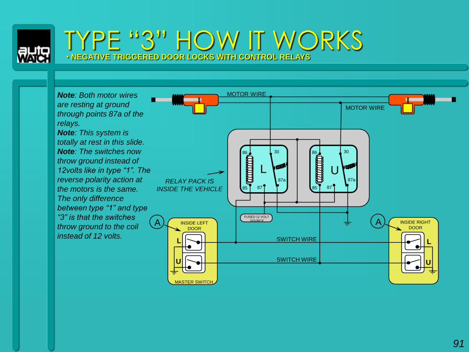
TYPE “3” HOW IT WORKS• NEGATIVE TRIGGERED DOOR LOCKS WITH CONTROL RELAYS
Note: Both motor wires
are resting at ground
through points 87a of the
relays.
Note: This system is
totally at rest in this slide.
Note: The switches now
throw ground instead of
12volts like in type “1”. The
reverse polarity action at
the motors is the same.
The only difference
between type “1” and type
“3” is that the switches
throw ground to the coil
instead of 12 volts.
86 30
87a
8785
L
86 30
87a
8785
INSIDE LEFT
DOOR
L
U
MASTER SWITCH
INSIDE RIGHT
DOOR
L
U
FUSED 12 VOLT
SOURCEA
U
A
SWITCH WIRE
SWITCH WIRE
MOTOR WIRE
MOTOR WIRE
91
85 30
87a
8786
L
86 30
87a
8785
INSIDE LEFT
DOOR
L
U
MASTER SWITCH
INSIDE RIGHT
DOOR
L
U
FUSED 12 VOLT
SOURCE
TYPE “3” HOW IT WORKS• NEGATIVE TRIGGERED DOOR LOCKS WITH CONTROL RELAYS
A
U
A
SWITCH WIRE
SWITCH WIRE
MOTOR WIRE
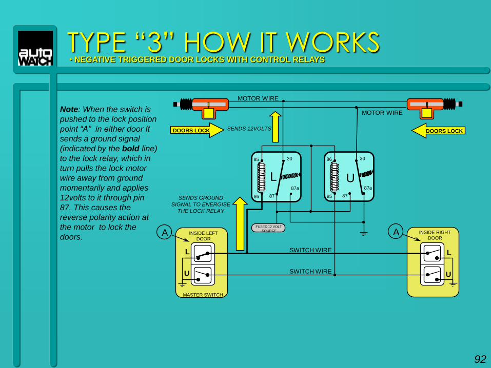
MOTOR WIRENote: When the switch is
pushed to the lock position
point “A” in either door It
sends a ground signal
(indicated by the bold line)
to the lock relay, which in
turn pulls the lock motor
wire away from ground
momentarily and applies
12volts to it through pin
87. This causes the
reverse polarity action at
the motor to lock the
doors.
SENDS GROUND
SIGNAL TO ENERGISE
THE LOCK RELAY
SENDS 12VOLTSDOORS LOCK DOORS LOCK
92
86 30
87a
8785
L
85 30
87a
8786
U
INSIDE LEFT
DOOR
L
U
MASTER SWITCH
INSIDE RIGHT
DOOR
L
U
FUSED 12 VOLT
SOURCE
TYPE “3” HOW IT WORKS• NEGATIVE TRIGGERED DOOR LOCKS WITH CONTROL RELAYS
AA
SWITCH WIRE
SWITCH WIRE
MOTOR WIRE
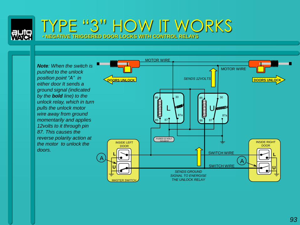
MOTOR WIRENote: When the switch is
pushed to the unlock
position point “A” in
either door It sends a
ground signal (indicated
by the bold line) to the
unlock relay, which in turn
pulls the unlock motor
wire away from ground
momentarily and applies
12volts to it through pin
87. This causes the
reverse polarity action at
the motor to unlock the
doors.
SENDS GROUND
SIGNAL TO ENERGISE
THE UNLOCK RELAY
SENDS 12VOLTSDOORS UNLOCK DOORS UNLOCK
93
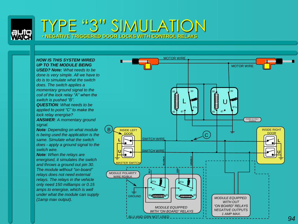
TYPE “3” SIMULATION• NEGATIVE TRIGGERED DOOR LOCKS WITH CONTROL RELAYS
HOW IS THIS SYSTEM WIRED
UP TO THE MODULE BEING
USED? Note: What needs to be
done is very simple. All we have to
do is to simulate what the switch
does. The switch applies a
momentary ground signal to the
coil of the lock relay “A” when the
switch is pushed “B”.
QUESTION: What needs to be
applied to point “C” to make the
lock relay energise?
ANSWER: A momentary ground
signal.
Note: Depending on what module
is being used the application is the
same. Simulate what the switch
does - apply a ground signal to the
switch wire.
Note: When the relays are
energised, it simulates the switch
and throws a ground out pin 30.
The module without “on-board”
relays does not need external
relays. The relays in the vehicle
only need 150 milliamps or 0.15
amps to energise, which is well
under what the module can supply
(1amp max output).
INSIDE RIGHT
DOOR
L
U
FUSED 12 VOLT
SOURCE
INSIDE LEFT
DOOR
L
U
MASTER SWITCH
B
SWITCH WIRE
SWITCH WIRE
C
86 30
87a
8785
L
86 30
87a
8785
U
MOTOR WIRE
MOTOR WIRE
MODULE EQUIPPED
WITH “ON BOARD” RELAYS
30
87a
87
86 85
30
87a
87
86 85GROUNDMODULE EQUIPPED
WITH OUT
“ON BOARD” RELAYS
NEGATIVE OUTPUTS
1 AMP MAX.
MODULE POLARITY
WIRE RD/BLK
BL
U/B
LK
BL
U
GR
N/B
LK
GR
N
BLU AND GRN NOT USED 94
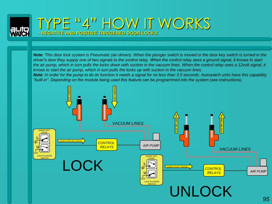
TYPE “4” HOW IT WORKS• NEGATIVE AND POSITIVE TRIGGERED DOOR LOCKS
Note: This door lock system is Pneumatic (air-driven). When the plunger switch is moved or the door key switch is turned in the
driver‟s door they supply one of two signals to the control relay. When the control relay sees a ground signal, it knows to start
the air pump, which in turn pulls the locks down with suction in the vacuum lines. When the control relay sees a 12volt signal, it
knows to start the air pump, which in turn pulls the locks up with suction in the vacuum lines.
Note: In order for the pump to do its function it needs a signal for no less than 3.5 seconds. Autowatch units have this capability
“built-in”. Depending on the module being used this feature can be programmed into the system (see instructions).
CONTROL
RELAYS
INSIDE LEFT
DOOR
L
U
LOCK PLUNGER
SWITCH
12V
AIR PUMP
VACUUM LINES
SENDS GROUND SIGNAL
DO
OR
S L
OC
K
DO
OR
S L
OC
K
LOCK CONTROL
RELAYS
INSIDE LEFT
DOOR
L
U
LOCK PLUNGER
SWITCH
12V
AIR PUMP
VACUUM LINES
SENDS 12VOLT SIGNAL
DO
OR
S U
NL
OC
K
DO
OR
S U
NL
OC
K
UNLOCK95
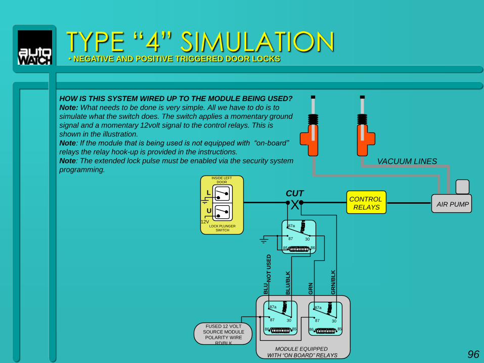
TYPE “4” SIMULATION• NEGATIVE AND POSITIVE TRIGGERED DOOR LOCKS
HOW IS THIS SYSTEM WIRED UP TO THE MODULE BEING USED?
Note: What needs to be done is very simple. All we have to do is to
simulate what the switch does. The switch applies a momentary ground
signal and a momentary 12volt signal to the control relays. This is
shown in the illustration.
Note: If the module that is being used is not equipped with “on-board”
relays the relay hook-up is provided in the instructions.
Note: The extended lock pulse must be enabled via the security system
programming.
CONTROL
RELAYS
INSIDE LEFT
DOOR
L
U
LOCK PLUNGER
SWITCH
12V
AIR PUMP
VACUUM LINES
CUT
X
30
87a
87
85 86
NO
T U
SE
D
MODULE EQUIPPED
WITH “ON BOARD” RELAYS
30
87a
87
86 85
30
87a
87
86 85
BL
U/B
LK
BL
U
GR
N/B
LK
GR
N
FUSED 12 VOLT
SOURCE MODULE
POLARITY WIRE
RD/BLK
96
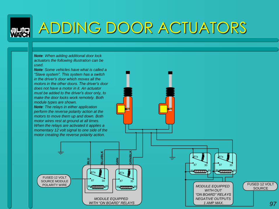
ADDING DOOR ACTUATORS
FUSED 12 VOLT
SOURCE MODULE
POLARITY WIRE
MODULE EQUIPPED
WITH “ON BOARD” RELAYS
30
87a
87
86 85
30
87a
87
86 85 MODULE EQUIPPED
WITH OUT
“ON BOARD” RELAYS
NEGATIVE OUTPUTS
1 AMP MAX.
30
87a
87
86 85
30
87a
87
86 85
FUSED 12 VOLT
SOURCE
BL
U/B
LK
BL
U
GR
N/B
LK
GR
N
Note: When adding additional door lock
actuators the following illustration can be
used.
Note: Some vehicles have what is called a
“Slave system”. This system has a switch
in the driver‟s door which moves all the
motors in the other doors. The driver‟s door
does not have a motor in it. An actuator
must be added to the driver‟s door only, to
make the door locks work remotely. Both
module types are shown.
Note: The relays in either application
perform the reverse polarity action at the
motors to move them up and down. Both
motor wires rest at ground at all times.
When the relays are activated it applies a
momentary 12 volt signal to one side of the
motor creating the reverse polarity action.
97

98
TEST EQUIPMENT

TEST EQUIPMENT
HIGH TECH VEHICLE ELECTRONICS Almost every vehicle manufactured today incorporates one
or more on board computers to control functions such as ABS braking, SRS airbag, fuel delivery, interior and exterior lighting systems and the list goes on and on. These computer-based systems are very sensitive to electrical voltages and cannot tolerate careless testing procedures or use of incompatible testing devices like a test light. The test light has a very low input resistance, demanding excessive current from the circuit being tested can result in a costly computer replacement.
99
SAFETY PRECAUTIONS
Whenever working on or around vehicle computer or microprocessor controlled alarm system components, some general precautions should be taken to avoid damage to vehicle and alarm system electrical components.
– 1. Never use test lights or other equipment that may demand more than 5mA of current from the circuit being tested.
– 2. Never install or remove battery cables or wiring harness connectors with the ignition key in the ON position or the engine running.
– 3. Always remove the battery cables when charging the battery, especially when using high current output boosters.
100
SAFETY PRECAUTIONS CONT.
– 4. Always fuse any power/polarity wires to the security
system. Some ignition switch harness wires found in a
vehicle may not be fused.
– 5. When working on new vehicles and wiring colour
information is not available, check all circuits needed
for installation, verify polarities, then disconnect battery
before doing actual wire connections.
Note: Some high end vehicles may lose memory.
Always check owner‟s manual before battery
disconnection.
101
TEST EQUIPMENT
TEST LIGHTS A 12 volt test light is used to check circuits and components
while electrical current is flowing through them. The test light will not detect or measure that a full +12 volts is present; it only detects that some voltage is present. This makes the test light almost useless as a troubleshooting tool. It can also damage microprocessors because the average test light pulls around 1 Amp which the microprocessor cannot supply. Microprocessor inputs and outputs are rated at less than 20 milliamps. By putting a load of more than 20 milliamps on the microprocessor you can easily damage it.
CAUTION: Autowatch does not recommend the use of test lights or any testing devices with a low input impedance, this can damage on-board computer systems
102
TEST EQUIPMENT
LOGIC PROBES A logic probe functions similar to the test light but unlike the
test light a logic probe is usually “computer safe,” meaning the device has a high input resistance (greater than 20,000 Ohms). Meaning it will not put a load on the circuit. The logic probe is usually equipped with two L.E.D.s. Red tells you that some positive voltage is present in the circuit (usually anything greater than 5 volts). The second L.E.D., green, indicates that a ground is present. However the logic probe is unable to determine that a full 12 volts is actually present in a circuit. This device can also affect the normal operation of the vehicle‟s circuit.(i.e. Intrepid door locks quit working when a logic probe is connected to the lock or unlock wires).
103
TEST EQUIPMENT
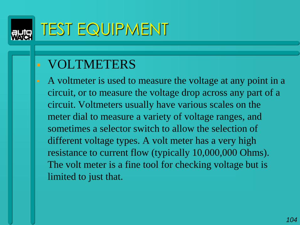
VOLTMETERS A voltmeter is used to measure the voltage at any point in a
circuit, or to measure the voltage drop across any part of a
circuit. Voltmeters usually have various scales on the
meter dial to measure a variety of voltage ranges, and
sometimes a selector switch to allow the selection of
different voltage types. A volt meter has a very high
resistance to current flow (typically 10,000,000 Ohms).
The volt meter is a fine tool for checking voltage but is
limited to just that.
104

TEST EQUIPMENT
MULTIMETERS Different combinations of test meters can be built into a
single unit designed for specific tests. Some of the more
common types are known as Volt/Amp testers, Tach/Dwell
meters or digital multimeters. Because the Multimeter is
able to provide the most information in testing and
troubleshooting vehicle circuits, it has become the meter of
choice for most technicians.
105
METER
WORKSHOP &
HOW CIRCUITS
WORK106
VHz
s
V
mV
A
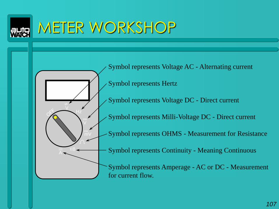
Symbol represents Voltage AC - Alternating current
Symbol represents Hertz
Symbol represents Voltage DC - Direct current
Symbol represents Milli-Voltage DC - Direct current
Symbol represents OHMS - Measurement for Resistance
Symbol represents Continuity - Meaning Continuous
Symbol represents Amperage - AC or DC - Measurement
for current flow.
METER WORKSHOP
107
METER WORKSHOP
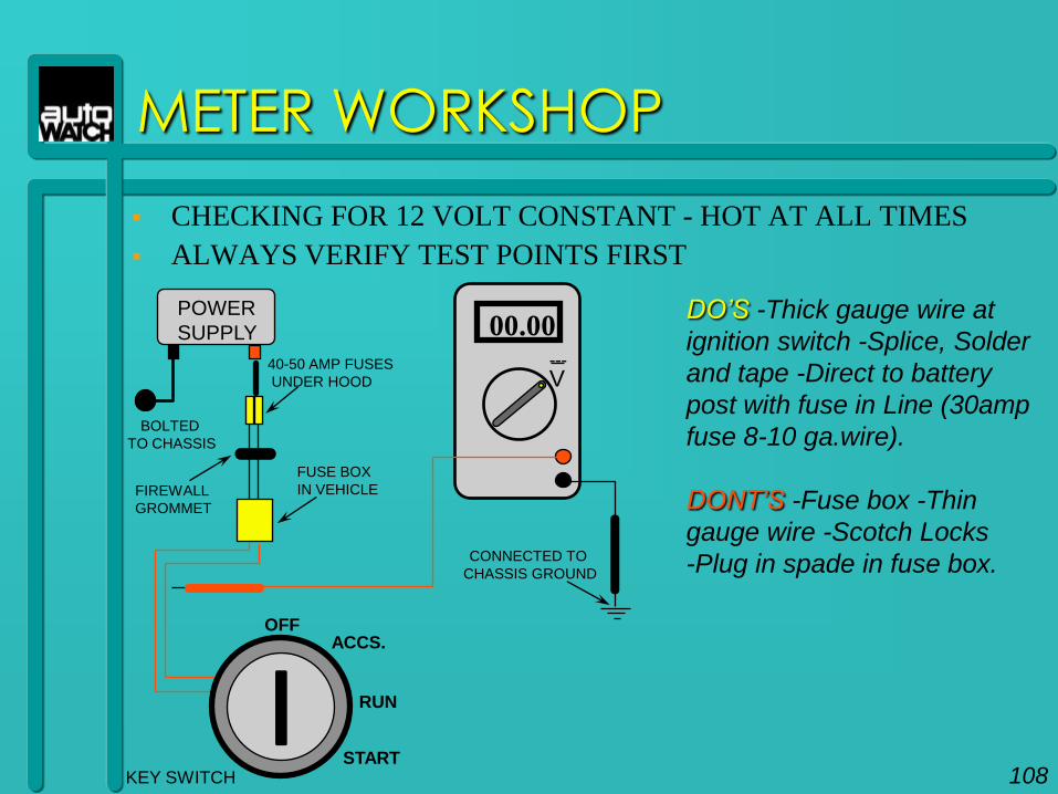
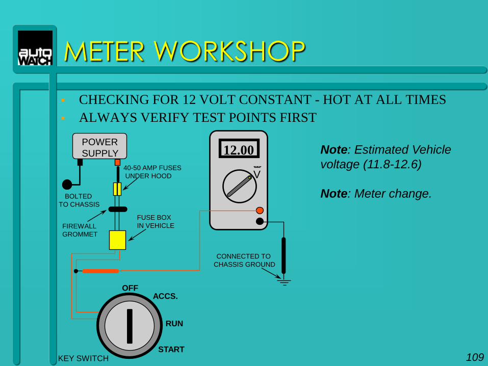
CHECKING FOR 12 VOLT CONSTANT - HOT AT ALL TIMES
ALWAYS VERIFY TEST POINTS FIRST
BOLTED
TO CHASSIS
40-50 AMP FUSES
UNDER HOOD
FIREWALL
GROMMET
ACCS.OFF
RUN
START
FUSE BOX
IN VEHICLE
POWER
SUPPLY
V
00.00---
DO‟S -Thick gauge wire at
ignition switch -Splice, Solder
and tape -Direct to battery
post with fuse in Line (30amp
fuse 8-10 ga.wire).
DONT‟S -Fuse box -Thin
gauge wire -Scotch Locks
-Plug in spade in fuse box.CONNECTED TO
CHASSIS GROUND
KEY SWITCH 108
METER WORKSHOP
CHECKING FOR 12 VOLT CONSTANT - HOT AT ALL TIMES
ALWAYS VERIFY TEST POINTS FIRST
BOLTED
TO CHASSIS
40-50 AMP FUSES
UNDER HOOD
FIREWALL
GROMMET
ACCS.OFF
RUN
START
FUSE BOX
IN VEHICLE
POWER
SUPPLY
V
12.00---
CONNECTED TO
CHASSIS GROUND
KEY SWITCH
Note: Estimated Vehicle
voltage (11.8-12.6)
Note: Meter change.
109
METER WORKSHOP
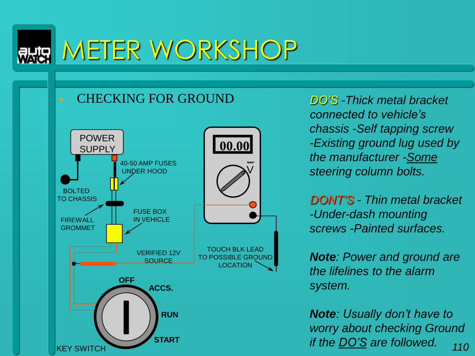
CHECKING FOR GROUND
BOLTED
TO CHASSIS
40-50 AMP FUSES
UNDER HOOD
FIREWALL
GROMMET
ACCS.OFF
RUN
START
FUSE BOX
IN VEHICLE
POWER
SUPPLY
V
00.00---
DO‟S -Thick metal bracket
connected to vehicle‟s
chassis -Self tapping screw
-Existing ground lug used by
the manufacturer -Some
steering column bolts.
DONT‟S - Thin metal bracket
-Under-dash mounting
screws -Painted surfaces.
Note: Power and ground are
the lifelines to the alarm
system.
Note: Usually don‟t have to
worry about checking Ground
if the DO‟S are followed.
TOUCH BLK LEAD
TO POSSIBLE GROUND
LOCATION
KEY SWITCH
VERIFIED 12V
SOURCE
110
METER WORKSHOP
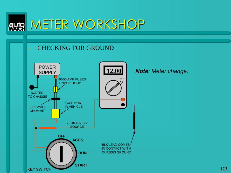
CHECKING FOR GROUND
BOLTED
TO CHASSIS
40-50 AMP FUSES
UNDER HOOD
FIREWALL
GROMMET
ACCS.OFF
RUN
START
FUSE BOX
IN VEHICLE
POWER
SUPPLY
V
12.00---
Note: Meter change.
KEY SWITCH
VERIFIED 12V
SOURCE
BLK LEAD COMES
IN CONTACT WITH
CHASSIS GROUND
111
METER WORKSHOP
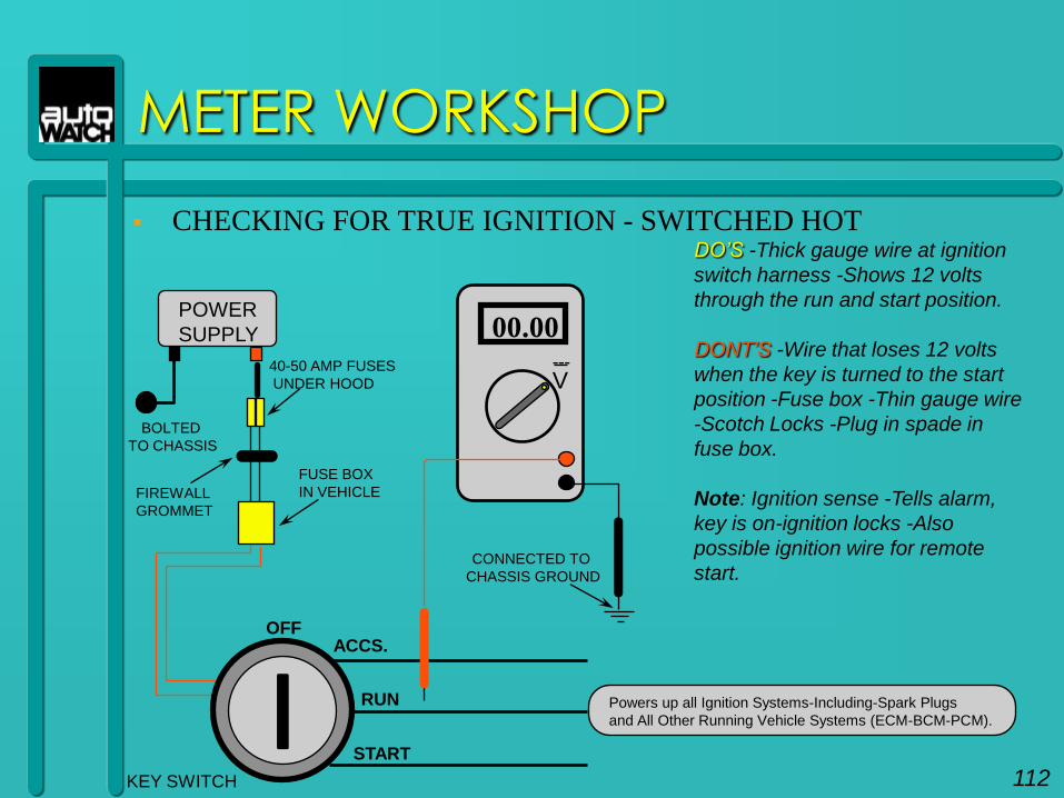
CHECKING FOR TRUE IGNITION - SWITCHED HOT
BOLTED
TO CHASSIS
40-50 AMP FUSES
UNDER HOOD
FIREWALL
GROMMET
ACCS.OFF
RUN
START
FUSE BOX
IN VEHICLE
POWER
SUPPLY
V
00.00---
CONNECTED TO
CHASSIS GROUND
KEY SWITCH
DO‟S -Thick gauge wire at ignition
switch harness -Shows 12 volts
through the run and start position.
DONT‟S -Wire that loses 12 volts
when the key is turned to the start
position -Fuse box -Thin gauge wire
-Scotch Locks -Plug in spade in
fuse box.
Note: Ignition sense -Tells alarm,
key is on-ignition locks -Also
possible ignition wire for remote
start.
Powers up all Ignition Systems-Including-Spark Plugs
and All Other Running Vehicle Systems (ECM-BCM-PCM).
112
METER WORKSHOP
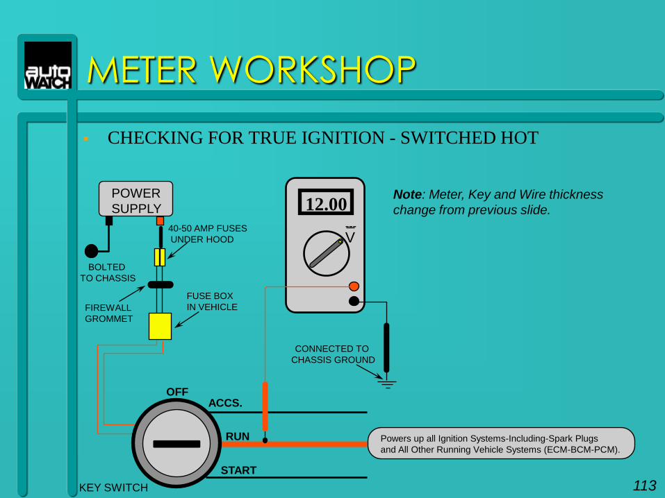
CHECKING FOR TRUE IGNITION - SWITCHED HOT
BOLTED
TO CHASSIS
40-50 AMP FUSES
UNDER HOOD
FIREWALL
GROMMET
ACCS.OFF
RUN
START
FUSE BOX
IN VEHICLE
POWER
SUPPLY
V
12.00---
CONNECTED TO
CHASSIS GROUND
KEY SWITCH
Powers up all Ignition Systems-Including-Spark Plugs
and All Other Running Vehicle Systems (ECM-BCM-PCM).
Note: Meter, Key and Wire thickness
change from previous slide.
113
METER WORKSHOP
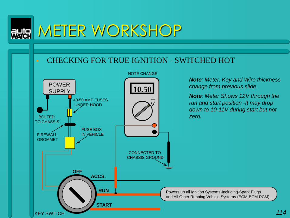
CHECKING FOR TRUE IGNITION - SWITCHED HOT
BOLTED
TO CHASSIS
40-50 AMP FUSES
UNDER HOOD
FIREWALL
GROMMET
ACCS.OFF
RUN
START
FUSE BOX
IN VEHICLE
POWER
SUPPLY
V
10.50---
CONNECTED TO
CHASSIS GROUND
KEY SWITCH
NOTE CHANGE
Powers up all Ignition Systems-Including-Spark Plugs
and All Other Running Vehicle Systems (ECM-BCM-PCM).
Note: Meter Shows 12V through the
run and start position -It may drop
down to 10-11V during start but not
zero.
Note: Meter, Key and Wire thickness
change from previous slide.
114
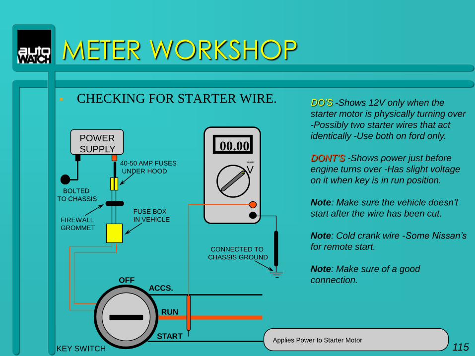
CHECKING FOR STARTER WIRE.
METER WORKSHOP
BOLTED
TO CHASSIS
40-50 AMP FUSES
UNDER HOOD
FIREWALL
GROMMET
ACCS.OFF
RUN
START
FUSE BOX
IN VEHICLE
POWER
SUPPLY
V
00.00---
CONNECTED TO
CHASSIS GROUND
KEY SWITCH
DO‟S -Shows 12V only when the
starter motor is physically turning over
-Possibly two starter wires that act
identically -Use both on ford only.
DONT‟S -Shows power just before
engine turns over -Has slight voltage
on it when key is in run position.
Note: Make sure the vehicle doesn‟t
start after the wire has been cut.
Note: Cold crank wire -Some Nissan‟s
for remote start.
Note: Make sure of a good
connection.
Applies Power to Starter Motor
115
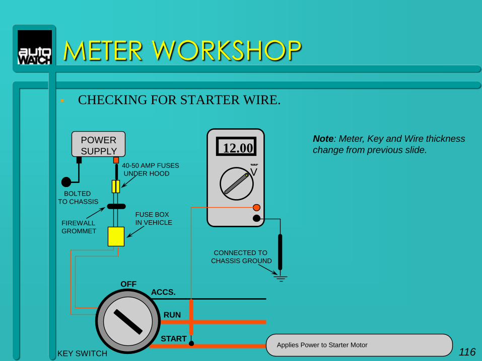
CHECKING FOR STARTER WIRE.
METER WORKSHOP
BOLTED
TO CHASSIS
40-50 AMP FUSES
UNDER HOOD
FIREWALL
GROMMET
ACCS.OFF
RUN
START
FUSE BOX
IN VEHICLE
POWER
SUPPLY
V
12.00---
CONNECTED TO
CHASSIS GROUND
KEY SWITCHApplies Power to Starter Motor
Note: Meter, Key and Wire thickness
change from previous slide.
116
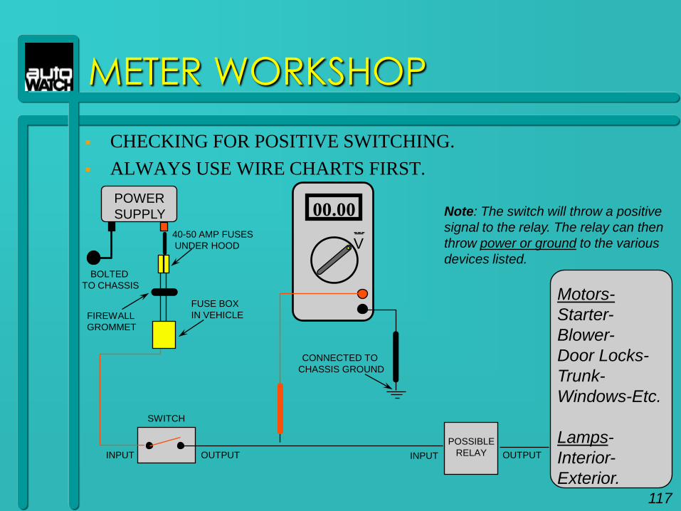
CHECKING FOR POSITIVE SWITCHING.
ALWAYS USE WIRE CHARTS FIRST.
METER WORKSHOP
BOLTED
TO CHASSIS
40-50 AMP FUSES
UNDER HOOD
FIREWALL
GROMMET
FUSE BOX
IN VEHICLE
POWER
SUPPLY
V
00.00---
CONNECTED TO
CHASSIS GROUND
Note: The switch will throw a positive
signal to the relay. The relay can then
throw power or ground to the various
devices listed.
SWITCH
INPUT OUTPUT
POSSIBLE
RELAYINPUT OUTPUT
Motors-
Starter-
Blower-
Door Locks-
Trunk-
Windows-Etc.
Lamps-
Interior-
Exterior.117
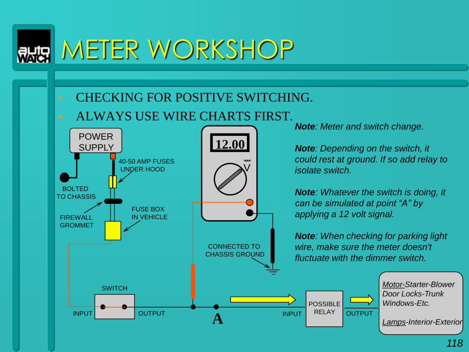
CHECKING FOR POSITIVE SWITCHING.
ALWAYS USE WIRE CHARTS FIRST.
METER WORKSHOP
BOLTED
TO CHASSIS
40-50 AMP FUSES
UNDER HOOD
FIREWALL
GROMMET
FUSE BOX
IN VEHICLE
POWER
SUPPLY
V
12.00---
CONNECTED TO
CHASSIS GROUND
Note: Meter and switch change.
Note: Depending on the switch, it
could rest at ground. If so add relay to
isolate switch.
Note: Whatever the switch is doing, it
can be simulated at point “A” by
applying a 12 volt signal.
Note: When checking for parking light
wire, make sure the meter doesn't
fluctuate with the dimmer switch.
SWITCH
INPUT OUTPUT
POSSIBLE
RELAYINPUT OUTPUT
Motor-Starter-Blower
Door Locks-Trunk
Windows-Etc.
Lamps-Interior-ExteriorA
118
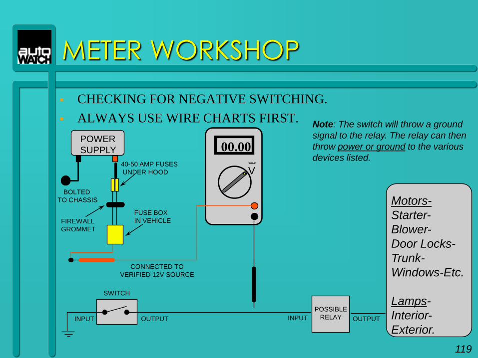
CHECKING FOR NEGATIVE SWITCHING.
ALWAYS USE WIRE CHARTS FIRST.
METER WORKSHOP
BOLTED
TO CHASSIS
40-50 AMP FUSES
UNDER HOOD
FIREWALL
GROMMET
FUSE BOX
IN VEHICLE
POWER
SUPPLY
V
00.00---
CONNECTED TO
VERIFIED 12V SOURCE
Note: The switch will throw a ground
signal to the relay. The relay can then
throw power or ground to the various
devices listed.
SWITCH
INPUT OUTPUT
POSSIBLE
RELAYINPUT OUTPUT
Motors-
Starter-
Blower-
Door Locks-
Trunk-
Windows-Etc.
Lamps-
Interior-
Exterior.
119
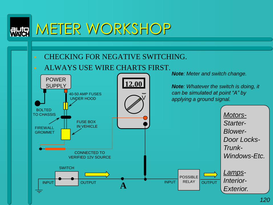
CHECKING FOR NEGATIVE SWITCHING.
ALWAYS USE WIRE CHARTS FIRST.
METER WORKSHOP
BOLTED
TO CHASSIS
40-50 AMP FUSES
UNDER HOOD
FIREWALL
GROMMET
FUSE BOX
IN VEHICLE
POWER
SUPPLY
V
12.00---
CONNECTED TO
VERIFIED 12V SOURCE
SWITCH
INPUT OUTPUT
POSSIBLE
RELAYINPUT OUTPUT
A
Note: Meter and switch change.
Note: Whatever the switch is doing, it
can be simulated at point “A” by
applying a ground signal.
Motors-
Starter-
Blower-
Door Locks-
Trunk-
Windows-Etc.
Lamps-
Interior-
Exterior.
120
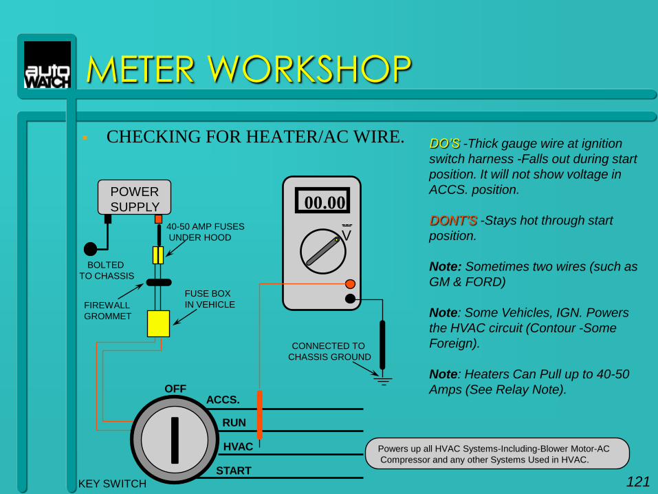
CHECKING FOR HEATER/AC WIRE.
METER WORKSHOP
BOLTED
TO CHASSIS
40-50 AMP FUSES
UNDER HOOD
FIREWALL
GROMMET
ACCS.OFF
HVAC
START
FUSE BOX
IN VEHICLE
POWER
SUPPLY
V
00.00---
CONNECTED TO
CHASSIS GROUND
KEY SWITCH
DO‟S -Thick gauge wire at ignition
switch harness -Falls out during start
position. It will not show voltage in
ACCS. position.
DONT‟S -Stays hot through start
position.
Note: Sometimes two wires (such as
GM & FORD)
Note: Some Vehicles, IGN. Powers
the HVAC circuit (Contour -Some
Foreign).
Note: Heaters Can Pull up to 40-50
Amps (See Relay Note).
Powers up all HVAC Systems-Including-Blower Motor-AC
Compressor and any other Systems Used in HVAC.
RUN
121
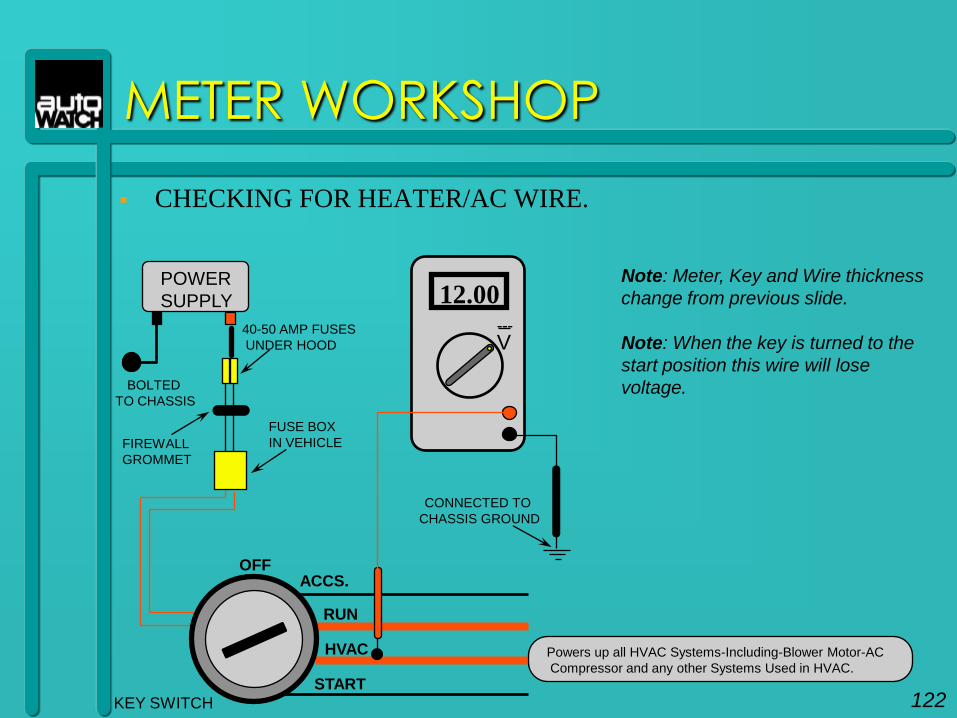
CHECKING FOR HEATER/AC WIRE.
METER WORKSHOP
BOLTED
TO CHASSIS
40-50 AMP FUSES
UNDER HOOD
FIREWALL
GROMMET
ACCS.OFF
HVAC
START
FUSE BOX
IN VEHICLE
POWER
SUPPLY
V
12.00---
CONNECTED TO
CHASSIS GROUND
KEY SWITCH
Powers up all HVAC Systems-Including-Blower Motor-AC
Compressor and any other Systems Used in HVAC.
RUN
Note: Meter, Key and Wire thickness
change from previous slide.
Note: When the key is turned to the
start position this wire will lose
voltage.
122
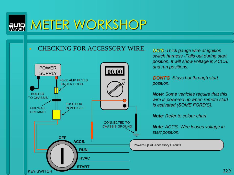
CHECKING FOR ACCESSORY WIRE.
METER WORKSHOP
BOLTED
TO CHASSIS
40-50 AMP FUSES
UNDER HOOD
FIREWALL
GROMMET
ACCS.OFF
HVAC
START
FUSE BOX
IN VEHICLE
POWER
SUPPLY
V
00.00---
CONNECTED TO
CHASSIS GROUND
KEY SWITCH
DO‟S -Thick gauge wire at ignition
switch harness -Falls out during start
position. It will show voltage in ACCS.
and run positions.
DONT‟S -Stays hot through start
position.
Note: Some vehicles require that this
wire is powered up when remote start
is activated (SOME FORD‟S).
Note: Refer to colour chart.
Note: ACCS. Wire looses voltage in
start position.
Powers up All Accessory Circuits
RUN
123
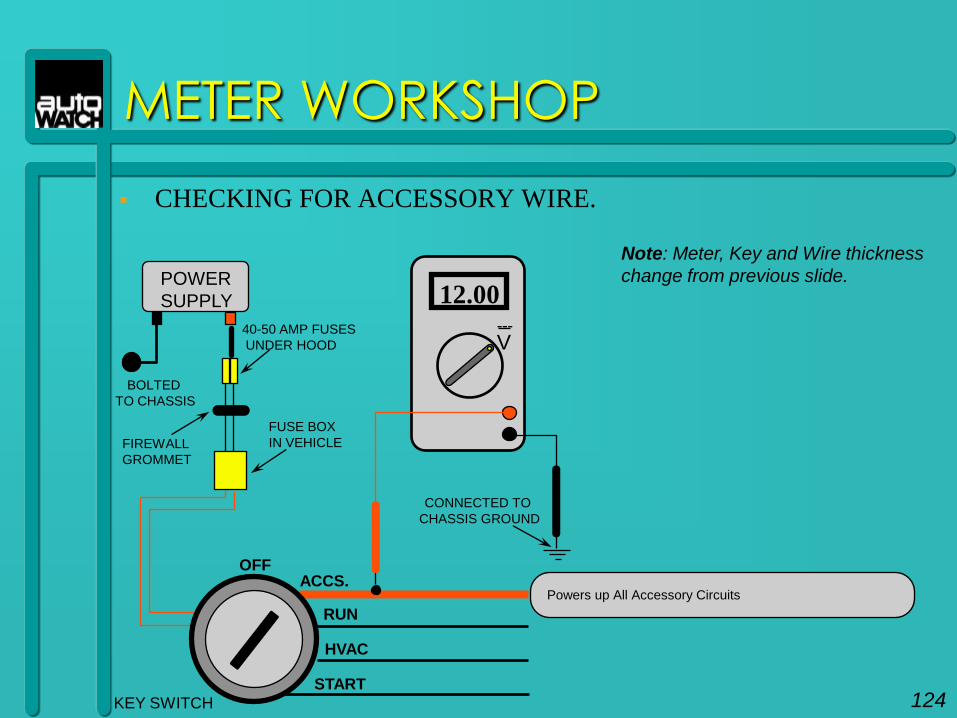
CHECKING FOR ACCESSORY WIRE.
METER WORKSHOP
BOLTED
TO CHASSIS
40-50 AMP FUSES
UNDER HOOD
FIREWALL
GROMMET
ACCS.OFF
HVAC
START
FUSE BOX
IN VEHICLE
POWER
SUPPLY
V
12.00---
CONNECTED TO
CHASSIS GROUND
KEY SWITCH
Powers up All Accessory Circuits
RUN
Note: Meter, Key and Wire thickness
change from previous slide.
124
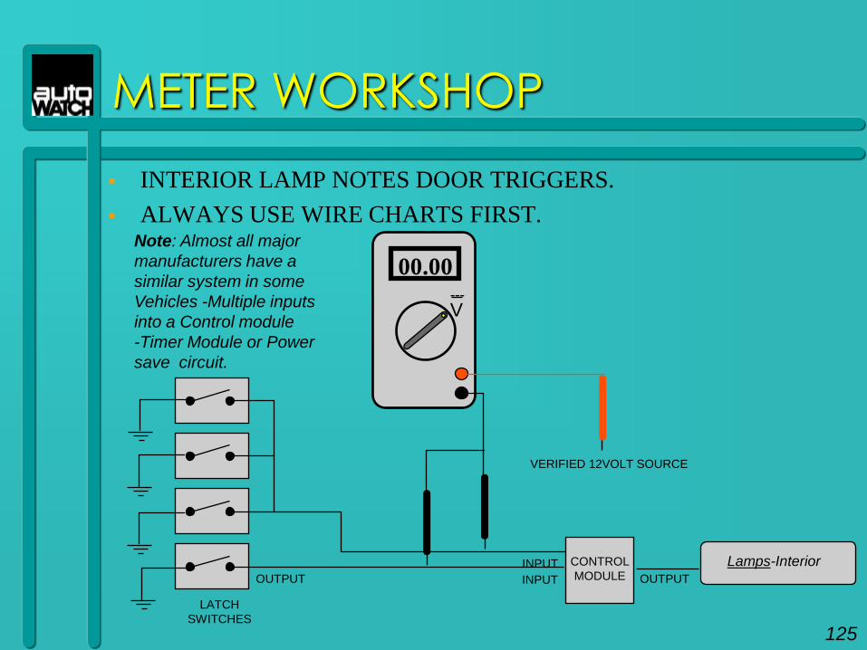
INTERIOR LAMP NOTES DOOR TRIGGERS.
ALWAYS USE WIRE CHARTS FIRST.
METER WORKSHOP
V
00.00---
LATCH
SWITCHES
OUTPUT
CONTROL
MODULEINPUT OUTPUT
Lamps-Interior
Note: Almost all major
manufacturers have a
similar system in some
Vehicles -Multiple inputs
into a Control module
-Timer Module or Power
save circuit.
INPUT
VERIFIED 12VOLT SOURCE
125
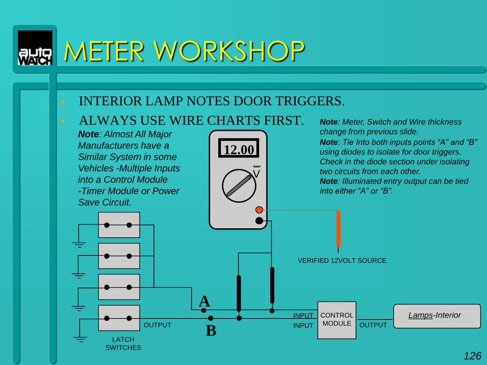
INTERIOR LAMP NOTES DOOR TRIGGERS.
ALWAYS USE WIRE CHARTS FIRST.
METER WORKSHOP
V
12.00---
Note: Tie Into both inputs points “A” and “B”
using diodes to isolate for door triggers.
Check in the diode section under isolating
two circuits from each other.
Note: Illuminated entry output can be tied
into either “A” or “B”.
LATCH
SWITCHES
OUTPUT
CONTROL
MODULEINPUT OUTPUT
Lamps-Interior
Note: Almost All Major
Manufacturers have a
Similar System in some
Vehicles -Multiple Inputs
into a Control Module
-Timer Module or Power
Save Circuit.
INPUT
VERIFIED 12VOLT SOURCE
B
A
Note: Meter, Switch and Wire thickness
change from previous slide.
126
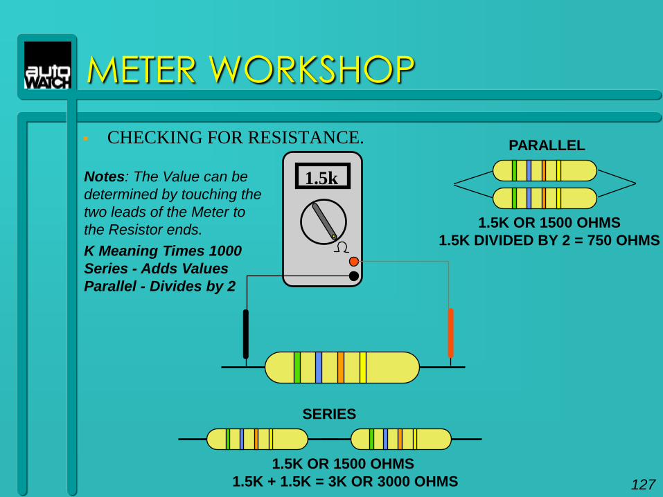
CHECKING FOR RESISTANCE.
METER WORKSHOP
1.5kNotes: The Value can be
determined by touching the
two leads of the Meter to
the Resistor ends.
K Meaning Times 1000
Series - Adds Values
Parallel - Divides by 2
PARALLEL
1.5K OR 1500 OHMS
1.5K DIVIDED BY 2 = 750 OHMS
1.5K OR 1500 OHMS
1.5K + 1.5K = 3K OR 3000 OHMS
SERIES
127
METER WORKSHOP
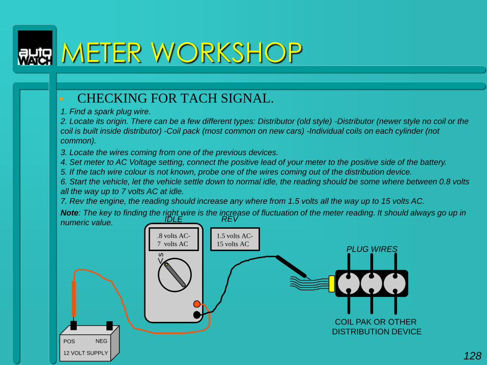
CHECKING FOR TACH SIGNAL.1. Find a spark plug wire.
2. Locate its origin. There can be a few different types: Distributor (old style) -Distributor (newer style no coil or the
coil is built inside distributor) -Coil pack (most common on new cars) -Individual coils on each cylinder (not
common).
3. Locate the wires coming from one of the previous devices.
4. Set meter to AC Voltage setting, connect the positive lead of your meter to the positive side of the battery.
5. If the tach wire colour is not known, probe one of the wires coming out of the distribution device.
6. Start the vehicle, let the vehicle settle down to normal idle, the reading should be some where between 0.8 volts
all the way up to 7 volts AC at idle.
7. Rev the engine, the reading should increase any where from 1.5 volts all the way up to 15 volts AC.
Note: The key to finding the right wire is the increase of fluctuation of the meter reading. It should always go up in
numeric value.
.8 volts AC-
7 volts AC
V
s
12 VOLT SUPPLY
POS NEG
COIL PAK OR OTHER
DISTRIBUTION DEVICE
PLUG WIRES
IDLE REV
1.5 volts AC-
15 volts AC
128
METER WORKSHOP
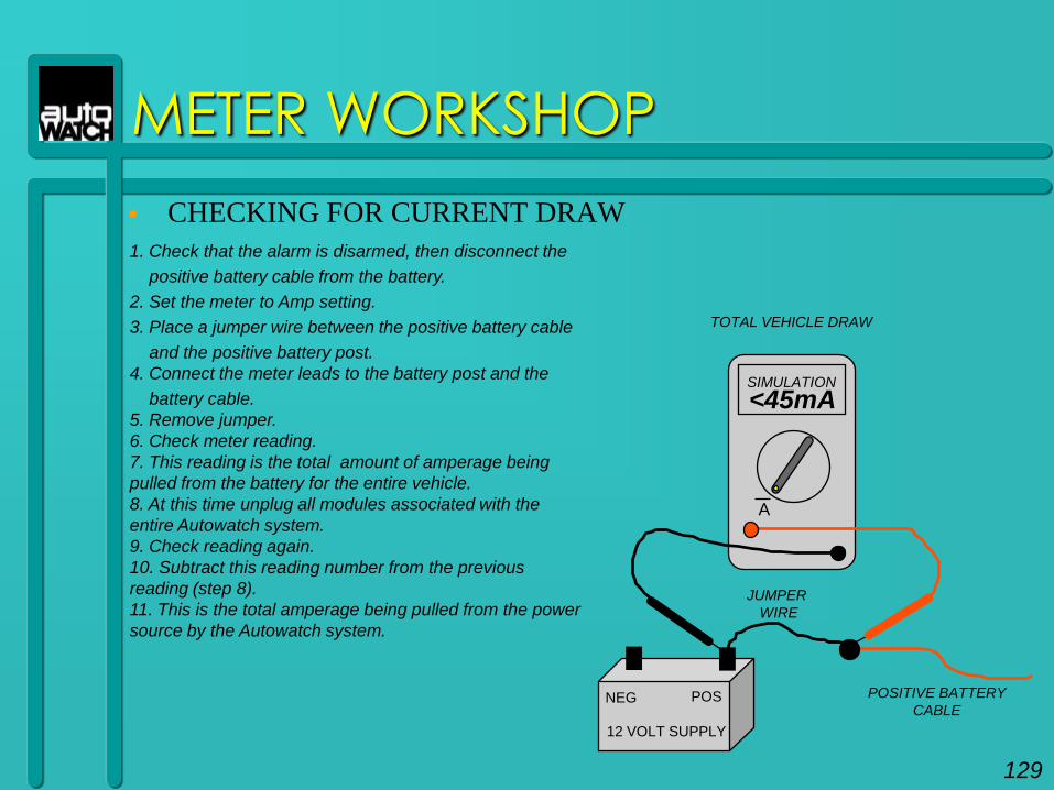
CHECKING FOR CURRENT DRAW
1. Check that the alarm is disarmed, then disconnect the
positive battery cable from the battery.
2. Set the meter to Amp setting.
3. Place a jumper wire between the positive battery cable
and the positive battery post.
4. Connect the meter leads to the battery post and the
battery cable.
5. Remove jumper.
6. Check meter reading.
7. This reading is the total amount of amperage being
pulled from the battery for the entire vehicle.
8. At this time unplug all modules associated with the
entire Autowatch system.
9. Check reading again.
10. Subtract this reading number from the previous
reading (step 8).
11. This is the total amperage being pulled from the power
source by the Autowatch system.
12 VOLT SUPPLY
NEG POS
A
129
POSITIVE BATTERY
CABLE
JUMPER
WIRE
<45mA
TOTAL VEHICLE DRAW
SIMULATION

130
THE KEYLESS
UPGRADE

THE KEYLESS UPGRADE
HOW DOES IT WORK?
Basically this system works exactly the same way as any other of our security
systems as far as security and features are concerned. The only difference is
the way it is turned „on‟ and „off‟. This system is used on vehicles that are
already equipped from the factory with remote keyless entry.
This system has 3 wires that are not on any of our other systems. They are
the „ARM‟ wire, The „DISARM‟ wire and the „UNLOCK SENSE‟ wire. Other
than these 3 wires the system works exactly the same. This system contains
no remote controls. It is operated by the factory keyless remote (FKR) that
comes with the vehicle from the factory.
HOW DOES THE FACTORY SYSTEM WORK?
When the LOCK button of the FKR is pushed it locks all doors. When the
UNLOCK button is pushed the FIRST time it unlocks the driver‟s door only.
When the UNLOCK button is pushed the SECOND time it unlocks the rest of
the doors (on most vehicles).
131

By connecting the ARM and DISARM wires from the Keyless Upgrade to the driver‟s
door motor Lock and Unlock wires, we now can use these signals to arm and disarm
the keyless upgrade system. That‟s how the Keyless Upgrade System works. It is
Armed and Disarmed through the driver‟s door motor wires. Simply put, when the
FKR is pushed to LOCK the factory keyless entry sends a 12volt signal to all lock
motors, which locks all the doors. When the FKR is pushed the first time to UNLOCK
the factory keyless entry system sends a 12volt signal to the driver‟s door motor only.
This in turn only unlocks the driver’s door. We use these two signals to turn the
Keyless Upgrade On and Off. If the UNLOCK button on the FKR is pushed again
within a few seconds the rest of the doors unlock.
Simply put, the Keyless Upgrade system is an alarm with 3 extra wires.
Hypothetically speaking; if the Keyless Upgrade System were to be completely
hooked-up minus the ARM and DISARM wires. The ARM and DISARM wires could
be manually applied to 12 volts and the system would ARM and DISARM. When the
ARM and DISARM inputs from the Keyless Upgrade System are tied into the driver‟s
door motor wires and the FKR is pushed to lock or unlock, this in what arms and
disarms the Keyless Upgrade System.
THE KEYLESS UPGRADE
132

With this in mind the driver‟s door switch in the door could now activate and deactivate the Keyless Upgrade. There's only one problem with that. If the thief were to break the window and push the unlock switch button in the driver‟s or passenger‟s door, the Keyless Upgrade would see a signal on the DISARM wire and shut the system off. That‟s where the UNLOCK SENSE wire comes in.
The UNLOCK SENSE wire is designed to be able to determine whether or not the remote is being pushed, or the physical switch in the driver‟s or passenger's door is being pushed. When the FKR is pushed the Keyless Upgrade System knows it‟s the customer. If the actual switch in either door is pushed to unlock, the Keyless Upgrade System knows to ignore this signal. This keeps the vehicle more secure because you can‟t break the window and then push the door unlock switch in the door to disarm the system.
THE KEYLESS UPGRADE
133
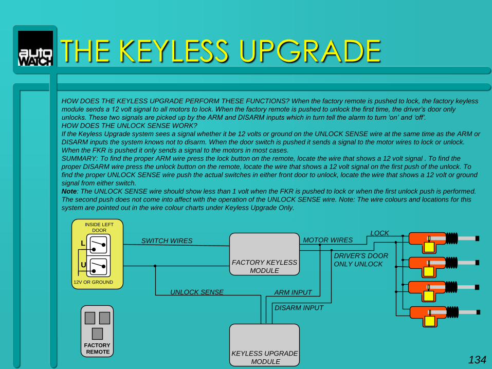
THE KEYLESS UPGRADE
KEYLESS UPGRADE
MODULE
FACTORY KEYLESS
MODULE
MOTOR WIRES
12V OR GROUND
INSIDE LEFT
DOOR
L
U
SWITCH WIRESLOCK
DRIVER‟S DOOR
ONLY UNLOCK
DISARM INPUT
ARM INPUTUNLOCK SENSE
HOW DOES THE KEYLESS UPGRADE PERFORM THESE FUNCTIONS? When the factory remote is pushed to lock, the factory keyless
module sends a 12 volt signal to all motors to lock. When the factory remote is pushed to unlock the first time, the driver‟s door only
unlocks. These two signals are picked up by the ARM and DISARM inputs which in turn tell the alarm to turn „on‟ and „off‟.
HOW DOES THE UNLOCK SENSE WORK?
If the Keyless Upgrade system sees a signal whether it be 12 volts or ground on the UNLOCK SENSE wire at the same time as the ARM or
DISARM inputs the system knows not to disarm. When the door switch is pushed it sends a signal to the motor wires to lock or unlock.
When the FKR is pushed it only sends a signal to the motors in most cases.
SUMMARY: To find the proper ARM wire press the lock button on the remote, locate the wire that shows a 12 volt signal . To find the
proper DISARM wire press the unlock button on the remote, locate the wire that shows a 12 volt signal on the first push of the unlock. To
find the proper UNLOCK SENSE wire push the actual switches in either front door to unlock, locate the wire that shows a 12 volt or ground
signal from either switch.
Note: The UNLOCK SENSE wire should show less than 1 volt when the FKR is pushed to lock or when the first unlock push is performed.
The second push does not come into affect with the operation of the UNLOCK SENSE wire. Note: The wire colours and locations for this
system are pointed out in the wire colour charts under Keyless Upgrade Only.
FACTORY
REMOTE
134
SUMMARY
When installing any aftermarket device always use common sense and neatness.
Always be careful.
Always make very solid connections.
Use the safety precautions as mentioned earlier.
Keep in mind that your customer is the most important person in the world.
Without them, none of us would be in business.
135