Embed Size (px)
Citation preview
DEPARTMENT OF EDUCATION & SCIENCE
Planning & Building Unit
Planning & Building Unit Building Section Department of
Education and Science Tullamore, Co. Offaly.
Telephone: (0506) 24300
Fax: (0506) 51119
Web: http://www.education.ie
Information and Communication Technology (ICT)
Infrastructure Guidelines For Post Primary Schools
TGD 005
First Edition February 2004
PLANNING & BUILDING UNIT
Information and Communication Technology (ICT) Infrastructure Guidelines for Post Primary Schools February 2004
Table of Contents
1.0 Introduction 3
2.0 Design Philosophy 4
2.1 General Design Philosophy 4
2.2 Standards 4
2.3 ICT Design Philosophy 4
2.4 Structured Cabling Systems 5
2.5 Local Area Network (LAN) 7
3.0 Communications Infrastructure 9
3.1 Data Communications Centre (DCC) 9
3.2 Main Distribution Facility (MDF) 9
3.3 Intermediate Distribution Facility (IDF) 9
4.0 Services Infrastructure 10
4.1 Services to Primary Data Communications Equipment 10
4.2 Services to Teaching Spaces and Other Rooms 11
4.3 General Structured Cabling Specification Requirements 14
4.4 General Specification Requirements 18
4.5 Lighting Requirements 22
5.0 Schedule of points 25
6.0 Documentation 27
7.0 Testing, Commissioning and Record Drawings 27
8.0 Training and Demonstration 28
Appendix A Completion Record Sheet 29

Information and Communication Technology (ICT) Infrastructure Guidelines for Post Primary Schools February 2004 1.0 Introduction All Post Primary School projects encompassing Information and Communication Technology (ICT), including those that are at Stage 3 or Pre Stage 3 planning at the time of issue of this document, must comply with these guidelines when developing subsequent stages. These guidelines relate to the integration of the infrastructure needs of Information and Communication Technology (ICT) with the building structure; they are for issue to school authorities (hereinafter referred to as the Client1) and to design teams and are intended for use in the design of new schools and extensions to existing schools. They are not intended to provide guidance on the management of ICT systems or software needs for schools. They replace all previously issued guidelines for ICT infrastructure in Post Primary schools. The guidelines reflect recent changes in the educational system in Ireland and changes in ICT technology and standards, they are based on Engineering Applications that work and suit the school environment best and not just best engineering practices. Where it is proposed to construct a new school these guidelines shall be applied in full. In the case of an extension project or refurbishment project, a flexible pragmatic approach shall be required, in these cases the Consultants shall identify any issues and agree a brief with the Planning and Building Unit prior to the commencement of design. This document does not relieve the Building Services Consulting Engineers from their normal design responsibilities. In applying these guidelines to projects, Schools, Clients and Design Team Consultants shall be obliged to comply in full with the Design Team Procedures and other guidance issued by the Department. In all instances, the Department of Education & Science shall have the final say in the application of these Guidelines to projects where grant-aid is to be sanctioned. For further advice on these or any other matter, please contact: The Planning & Building Unit Building Section Department of Education & Science Portlaoise Road, Tullamore, County Offaly. Telephone: 0506 24300 Fax: 0506 51119 Web: http://www.education.ie 1 In the case of Community and Comprehensive Schools the Minister for Education and Science is the
Client, but for the purposes of this document the term “Client” shall also encompass the School Authorities.
Page 3 of 29

Information and Communication Technology (ICT) Infrastructure Guidelines for Post Primary Schools February 2004 2.0 Design Philosophy
2.1 General Design Philosophy The different functions of the Design Team members shall be integrated, combining Building Services Engineering, Architectural Design, Structural Engineering and Quantity Surveying to create a well designed, sustainable, cost effective, durable low maintenance building. The design shall allow repair or replacement of components of the building such as fittings, finishes and services with minimum disruption and cost. To achieve this it is essential that all disciplines within the Design Team work together from the beginning of the project and that the design is developed through collaboration by all the Design Team members. The Building Services Consulting Engineer shall ensure that all potential costs that could arise during the execution of the contract and the installation and commissioning of the ICT Infrastructure to schools are provided for inclusion at the appropriate stage and in the appropriate manner; this also includes possible capital contributions for Internet access. The Capital contribution for supply and connection shall be included in the project cost but not in the tender documents. In the case of a school extension where an ICT system is to serve both the extension and the existing building, the cost shall be apportioned between new and existing on the basis of floor area. The portion of cost applicable to the extension is included in the basic building cost of the extension and the portion of cost applicable to the existing building is included in abnormal costs. 2.2 Standards
The International Standard for Generic Cabling Systems is ISO11801: 2002. All references to this standard, in this document, refer to this version. Where possible, International Organization for Standardization (ISO standards) are used in this document. Where two sets of standards exist with similar characteristics, it is expected that the ISO standard shall be applied. Standards noted are current at time of writing; the prevailing versions of these standards shall be used at time of design and installation. 2.3 ICT Design Philosophy All teaching and habitable rooms shall be networked. Each of these rooms will have one teacher position network point. In specialist rooms additional student position network points be provided as scheduled and shall be networked through a local switch, the Intermediate Distribution Facilities (IDF)
Page 4 of 29
Information and Communication Technology (ICT) Infrastructure Guidelines for Post Primary Schools February 2004 if applicable, or the Main Distribution Facility (MDF) which is located in the Data Communication Centre (DCC) whichever is the most economical. Other non-teaching Spaces as scheduled shall be provided with a network point. Descriptions of the above facilities are included in section 3. The locations of the computer area in each teaching space in existing schools shall be agreed with the Client prior to design; positions of network points in new schools shall be as indicated on the Department’s Standard Room Layout Drawings. Multiple points shall be positioned in the one area of the classroom. The position of network points in all offices shall be agreed with the school prior to design and co-ordinated with the furniture layouts. A dedicated Data Communication Centre (DCC) shall be provided as detailed in section 3. Internet access to schools shall be via either Analogue, ISDN, Broadband, Cable, Very Small Aperture Technology (VSAT) or Wireless services. The Building Services Consulting Engineers are required to report at Stage 2 on the various types of Internet access available in each situation. The intent shall be to provide the school with the fastest and most economical service available. 2.4 Structured Cabling Systems The primary network shall be designed as Category 5 enhanced / Class D to ISO 11801. The network shall be Fast Ethernet standard IEEE802.3u with auto-sensing switches. The specialising Building Services Consulting Engineer skilled in Local Area Networks (LAN) and Networking shall review the site and develop the cabling design. The ICT infrastructure for a new school shall be addressed at Stage 2. It is deemed appropriate that the structured cabling system be installed by suitably trained Electrical Contractors, or appropriately trained personnel; however, only specialist contractors shall be used to install fibre optic cabling. Telephony shall not be part of the ICT structured cabling system. Refer to “Mechanical & Electrical Building Services Engineering Guidelines For Post Primary schools” for details of telephony requirements. The infrastructure to be provided under the infrastructure-cabling contract shall include the structured cabling, RJ45 sockets, RJ45 patch panels and cabinets,
Page 5 of 29
Information and Communication Technology (ICT) Infrastructure Guidelines for Post Primary Schools February 2004 these shall all be compatible and from the same manufacturer to ensure optimum performance. The Client shall supply as part of the School equipment the router, servers and associated UPS, switches and patch leads in accordance with the Department’s ICT Equipment Guidelines. The following three scenarios represent the majority of Post Primary schools. 2.4.1 Single building within 90 metres. A school comprising one building where it is possible to reach each Primary Network point within 90 metres (actual cable run excluding patch leads) from the dedicated Data Communication Centre (DDC), which will house the Main Distribution Facility (MDF). 2.4.2 Single building not within 90 metres A school comprising one building where it is not possible to reach all network point within 90 metres (actual cable length excluding patch leads) from the dedicated Data Communication Centre, which will house the Main Distribution Facility (MDF). A building of this type will require Intermediate Distribution Facilities (IDF) to interconnect the system. The connection between an IDF and the MDF within the same building shall be Category 5e (enhanced) UTP cable when the distance involved is less than 90 metres. When this distance is greater alternative solutions such as fibre optic backbone cable or wireless shall be considered for this aspect of the system, whichever is the most economical and appropriate and a brief agreed with the Building Unit at Stage 2. 2.4.3 Multiple buildings Where a school comprises two or more buildings there may be different solutions depending on the possibility to reach each network point within 90 metres (actual cable run) of the dedicated Data Communication Centre. For the inter-connection between an IDF in a separate building or stand-alone Physical Education Hall and the MDF in the main building a multimode fibre optic backbone cable or a wireless connection shall be considered for this aspect of the system, whichever is the most economical and appropriate and a brief agreed with the Building Unit at Stage 2. The cabling where practicable shall be over ground and carried in the links between the buildings. Where this is not possible a completely sealed duct shall be provided with all bends having a radius suitable for the fibre optic cable.
Page 6 of 29
Information and Communication Technology (ICT) Infrastructure Guidelines for Post Primary Schools February 2004 2.5 Local Area Network (LAN) In all circumstances the Network shall be Fast Ethernet based. System Administration shall be part of the School’s Network Management Procedures. It is envisaged that there shall be minimum levels of access to the school network to facilitate different user groups, i.e. Students, Teachers, and Administrators. 2.5.1 Wireless Ethernet. In some existing schools it may not be possible to install a complete cabling installation. These may include a listed building, an existing larger school with limited distribution zones or existing remote buildings. In these cases wireless Ethernet may be considered as a component of an overall structured cabling infrastructure. This should be highlighted at Stage 2 and a brief agreed with the Building Unit. Each application shall be viewed individually and agreed between the Client and the Building Services Consultant Engineer as to its appropriateness.
Page 7 of 29
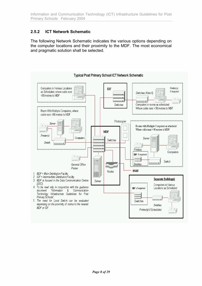
Information and Communication Technology (ICT) Infrastructure Guidelines for Post Primary Schools February 2004 2.5.2 ICT Network Schematic The following Network Schematic indicates the various options depending on the computer locations and their proximity to the MDF. The most economical and pragmatic solution shall be selected.
Page 8 of 29

Information and Communication Technology (ICT) Infrastructure Guidelines for Post Primary Schools February 2004 3.0 Communications Infrastructure This section details the communication infrastructure requirements. 3.1 Data Communications Centre (DCC) A dedicated Data Communication Centre (DCC) shall be provided, size 2 m x 2 m x full ceiling height (min 2.7 m) and shall have no windows. This room shall house the Main Distribution Facility (MDF). The DCC shall be suitably positioned off the circulation area or off a general store (subject to fire regulations) and be located in the main building. The room shall be fitted with a key operated lock as part of the master key suite of keys. The DCC shall be naturally ventilated with air inlets at low level and air outlets at high-level opening to the corridor or to the store. Ventilation to the outside is generally not required. The enclosure to this room should give a 30-minute fire rating; intumescent passive fire protection shall be used where necessary. The location should, as far as practicable, be such that the cable run (actual cable length) to all network points is within the limit of 90 metres. Only where this is not physically possible an Intermediate Distribution Facility (IDF) shall be provided as detailed below. 3.2 Main Distribution Facility (MDF) The MDF shall be located in the DCC in lockable floor mounted equipment cabinets as detailed in section 4.3.4. It shall be supplied with patch panels. The Client shall supply as part of the school’s equipment, the router, servers and associated UPS, switches and patch leads in accordance with the Department’s ICT Equipment Guidelines. 3.3 Intermediate Distribution Facility (IDF) An Intermediate Distribution Facility (IDF) shall be provided where the cable run from the DCC to any Primary network point exceeds 90 metres or for each separate building. (Extension or stand alone Physical Educational Hall). The IDF will contain a lockable wall mounted equipment cabinet as detailed in section 4.3.4. It shall be supplied with patch panels. The Client shall supply as part of the school’s equipment, servers and associated UPS, switches and patch leads in accordance with the Department’s
Page 9 of 29
Information and Communication Technology (ICT) Infrastructure Guidelines for Post Primary Schools February 2004 ICT Equipment Guidelines. The IDF shall be mounted at high level in a suitable position such as a store (not a teaching or habitable space). Ideally this space should not have a window but should be adequately ventilated to adjoining spaces. The room housing the IDF shall be fitted with a key operated lock as part of the master key suite of keys. 4.0 Services Infrastructure This section details the mechanical and electrical services associated with the ICT Infrastructure. 4.1 Services to Primary Data Communications Equipment The following outlines the requirements for services to the primary data communication equipment. 4.1.1 Data Communications Centre (DCC) A local electrical sub distribution board shall be provided in the DCC. The design capacity will need to be established on site but as a minimum a 35 A single-phase electrical supply shall be provided. A small Uninterrupted Power supply unit shall be considered for the main server to back up the electronic equipment. This unit shall be supplied and installed as part of the Client supplied equipment. Where 3 Phase power is available only one phase shall be used per room. A dedicated earth from the main earth bar at the main LV switchboard shall be provided to the DCC to serve each of the data cabinets. The design capacity will need to be established on site. A dedicated line (ExchL) from the telecommunications provider for Internet (WAN) connection shall be located in the room. A fire extinguisher shall be provided of suitable class for electrical equipment. A smoke detector shall be located in the room. As automatic fire suppression system will not be provided to protect data or equipment, a local management system shall be put in place to protect important stored information.
Page 10 of 29
Information and Communication Technology (ICT) Infrastructure Guidelines for Post Primary Schools February 2004 4.1.2 Main Distribution Facility (MDF) Power supply to each cabinet shall via a separate industrial type plug and socket to IS/EN 60309 from an MCB so as to eliminate the risk of nuisance tripping. This shall be terminated in a switched spur, with a trailer lead directly connected and mounted in the cabinet. Electrical Power Socket outlets shall be provided. The number of socket outlets can be calculated by dividing the number of network points by twenty-four. At least two additional socket outlets shall be provided for expansion. Surge protection shall be considered at the input to the LV board. In new schools this shall be provided on the main incoming electrical supply to the school and will not be necessary at this board. 4.1.3 Intermediate Distribution Facility (IDF) A local electrical sub distribution board shall be provided. The design capacity will need to be established on site but as a minimum a 35 A single-phase electrical supply shall be provided. Power supply to each cabinet shall via a separate industrial type plug and socket to IS/EN 60309 from an MCB so as to eliminate the risk of nuisance tripping. This shall be terminated in a switched spur, with a trailer lead directly connected and mounted in the cabinet. Electrical Power Socket outlets shall be provided. The number of socket outlets can be calculated by dividing the number of network points by twenty-four. At least two additional socket outlets shall be provided for expansion. A minimum of eight power outlets shall be provided. A fire extinguisher shall be provided of suitable class for electrical equipment. A smoke detector shall be located in the room. 4.2 Services to Teaching Spaces and Other Rooms The following outlines the requirements for services to the computer rooms, classrooms, specialist rooms and habitable rooms where network points are scheduled. 4.2.1 Services to Computer Rooms A key lockable local electrical distribution board shall be provided. Surge protection shall be considered at the input to the LV board. In new schools this shall be provided on the main incoming electrical supply to the school and will not be necessary at this board.
Page 11 of 29

Information and Communication Technology (ICT) Infrastructure Guidelines for Post Primary Schools February 2004 Local distribution within the room shall be via 100x50 mm three-compartment dado type trunking. Sockets and fixings used on this trunking shall be of the range recommended for the trunking. A unique key enabled switch (without emergency knock off facility) shall be located at the entrance to the room. This shall be capable of disabling all computer power sockets but not lighting. Three number unswitched 13 A sockets shall be allowed per computer station. No more than four stations (twelve sockets) shall be powered per RCD with appropriate MCB protection or whatever number of stations is recommended by respective manufacturers so as to eliminate the risk of nuisance tripping. A fused spur (unswitched) shall be provided at high level for power supply to the local switch if the network design is based on this option. Lighting shall be as detailed in section 4.5. The ventilation and heating services shall be as per “Mechanical & Electrical Building Services Engineering Guidelines For Post Primary schools”. Where a computer room is being newly designed there should be no need for mechanical cooling provided attention is given to issues such as heating controls, room configuration cross ventilation, solar gains and thermal mass. 4.2.2 Services to Teaching Spaces Each general classroom shall have one data point connected via the IDF or directly to the MDF whichever is more economical. The position of new network points in existing schools shall be agreed with the Client prior to design; positions of network points in new schools shall be as indicated on the standard room layout drawings. The data point shall be located in a position such that the equipment it serves will not have difficulty with glare and reflections on the screen. Where possible the computer position shall be on the corridor wall of the classroom. Local distribution within the room shall be via three-compartment trunking. The trunking shall drop directly from the service void above or rise directly from the service ceiling below. Four 13 A sockets shall be located adjacent to the data point in the vertical trunking. Horizontal trunking shall be avoided. These shall be wired directly to the local distribution board and shall be powered from a separate RCD with appropriate MCB protection.
Page 12 of 29
Information and Communication Technology (ICT) Infrastructure Guidelines for Post Primary Schools February 2004 The final position of the data and power outlets shall be above desk height. Sockets and fixings used on this trunking shall be of the range recommended for the trunking. Lighting shall be of direct type as per “Mechanical & Electrical Building Services Engineering Guidelines For Post Primary schools”. 4.2.3 Services to Specialist Rooms Each specialist room shall have network points as scheduled connected via a local switch, or via the IDF or directly to the MDF whichever is more economical. The position of new network points in existing schools shall be agreed with the Client prior to design; positions of network points in new schools shall be as indicated on the standard room layout drawings. These local network points shall ideally be in one area of the room on the corridor wall. Local distribution within the room shall be via 100x50 mm three-compartment dado type trunking. The final position of the data and power outlets shall be above desk height. Sockets and fixings used on this trunking shall be of the range recommended for the trunking. A fused spur (unswitched) shall be provided at high level for power supply to the local switch if the network design is based on this option. Three number unswitched 13A sockets shall be allowed per computer station and one per printer (as scheduled). No more than four stations (twelve sockets) shall be powered per RCD with appropriate MCB protection or whatever number of stations is recommended by respective manufacturers so as to eliminate the risk of nuisance tripping. The sockets shall be served from the specialist room’s local distribution board and be linked via a dedicated unique key enabled switch (without emergency knock off facility) located near the teacher’s desk. Lighting shall be of direct type only as per “Mechanical & Electrical Building Services Engineering Guidelines For Post Primary schools”. The demonstration room and lecture room are to be equipped for future LCD projector mounting points. Where suspended ceilings are proposed in these rooms a power socket shall be located on the ceiling (or in the ceiling void) approximately 5-6 metres from the centre of the teaching wall along with 2 x 25 mm conduits with draw wires to a double back box (on the teaching wall) for future signal cabling.
Page 13 of 29
Information and Communication Technology (ICT) Infrastructure Guidelines for Post Primary Schools February 2004 Plastic conduit is not recommended and should not be used. Conduit shall be secured every one metre horizontally and every 1.2 metres vertically. If there are no suspended ceilings and the design intent is that services are surface mounted then there is no need to make this provision. 4.2.4 Services to other rooms and areas All other rooms as scheduled shall be networked with each room having one networked point, connected via the IDF, or directly to the MDF whichever is the more economical. The position of the network points in existing schools shall be agreed with the Client prior to design; positions of network points in new schools shall be as indicated on the standard room layout drawings and by agreement with the school for general areas. Lighting shall be of direct type only using linear fluorescent fittings as per “Mechanical & Electrical Building Services Engineering Guidelines For Post Primary schools”. Local distribution within the room shall be via three-compartment trunking. The trunking shall drop directly from the service void above or rise directly from the service ceiling below. Four 13 A sockets shall be located adjacent to the data point in the vertical trunking. Horizontal trunking shall be avoided. These shall be wired directly to the local distribution board and shall be powered from a separate RCD with appropriate MCB protection. The final position of the data and power outlets shall be above desk height. Sockets and fixings used on this trunking shall be of the range recommended for the trunking. 4.3 General Structured Cabling Specification Requirements 4.3.1 Electromagnetic Compatibility (EMC) Compliance The EMC directive applies to requirements on emission and protection from electromagnetic interference in the EU. EN 55022 and EN55105 are the standards applicable to Information Technology. As the structured cabling system is a passive component, the EMC directive does not apply to the system, but to the final application. At time of writing, EMC test standards for links have not been finalised.
Page 14 of 29
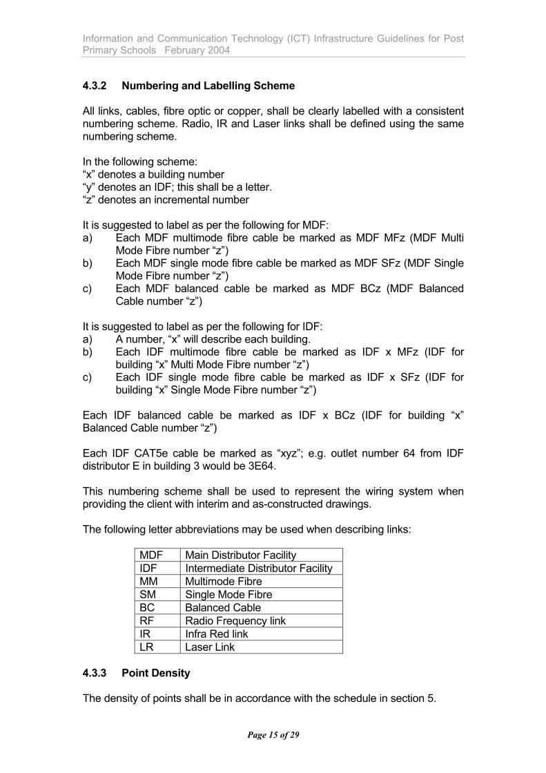
Information and Communication Technology (ICT) Infrastructure Guidelines for Post Primary Schools February 2004 4.3.2 Numbering and Labelling Scheme All links, cables, fibre optic or copper, shall be clearly labelled with a consistent numbering scheme. Radio, IR and Laser links shall be defined using the same numbering scheme. In the following scheme: “x” denotes a building number “y” denotes an IDF; this shall be a letter. “z” denotes an incremental number It is suggested to label as per the following for MDF: a) Each MDF multimode fibre cable be marked as MDF MFz (MDF Multi
Mode Fibre number “z”) b) Each MDF single mode fibre cable be marked as MDF SFz (MDF Single
Mode Fibre number “z”) c) Each MDF balanced cable be marked as MDF BCz (MDF Balanced
Cable number “z”) It is suggested to label as per the following for IDF: a) A number, “x” will describe each building. b) Each IDF multimode fibre cable be marked as IDF x MFz (IDF for
building “x” Multi Mode Fibre number “z”) c) Each IDF single mode fibre cable be marked as IDF x SFz (IDF for
building “x” Single Mode Fibre number “z”) Each IDF balanced cable be marked as IDF x BCz (IDF for building “x” Balanced Cable number “z”) Each IDF CAT5e cable be marked as “xyz”; e.g. outlet number 64 from IDF distributor E in building 3 would be 3E64. This numbering scheme shall be used to represent the wiring system when providing the client with interim and as-constructed drawings. The following letter abbreviations may be used when describing links:
MDF Main Distributor Facility IDF Intermediate Distributor Facility MM Multimode Fibre SM Single Mode Fibre BC Balanced Cable RF Radio Frequency link IR Infra Red link LR Laser Link
4.3.3 Point Density The density of points shall be in accordance with the schedule in section 5.
Page 15 of 29
Information and Communication Technology (ICT) Infrastructure Guidelines for Post Primary Schools February 2004 4.3.4 Cabinets Five types of cabinets are appropriate for general usage. Type 1 shall be min. 39U, w. 600, d. 600.This is the smallest usable cabinet for general equipment. Type 2 shall be min. 39U, w. 800, d. 600. This cabinet is for structured cabling where vertical cable management is required in the additional available 200 mm. Type 3 shall be min. 39U, w. 600, d. 910. This extra depth is required for rack-mounted servers. Type 4 shall be min. 39U, w. 800, d. 910. This cabinet is for all requirements in small schools (structured cabling, equipment, servers). Type 5 shall be min 6U, w. 600, d. 400. This cabinet is a wall-mounted unit to house switches. These items shall be selected to suit cabinet size. U = height unit = 44.5 mm All cabinets shall be 19” rack mounting type of a solid and durable type. Frame shall be of min. 2 mm steel, doors and panels of min.1.5 mm steel. Frame shall be seam-welded. All floor-mounted cabinets shall be supplied with a plinth. Plinth shall have side openings in each direction. Specified cabinets shall be suitable for computer room environments and shall conform to IP21 EN 60.529/IEC 529. Note that IP21 conformance is required on the installed cabinet after completion of installation. It is the installer’s responsibility to ensure that sufficient care is taken during installation to achieve this. Cabinets shall be supplied with lockable front doors with safety glazing. They may either be floor or wall mounted. Side and rear panels shall be of a steel construction and shall be removable. During installation, all adjacent cabinets shall be bolted together by the installer and only 2 side panels shall be required in total. Cabinets shall be installed such that all equipment including patch panels may be serviced and installed from the front. Cabinets shall be supplied with brush plates or other such entry mechanism to ensure that cable entries are tidy and sealed to IP21. Suppliers shall declare conformance or otherwise with regard to the EU EMC directive relating to electromagnetic interference, on the completed installation, EU 89 / 363 with all amendments.
Page 16 of 29
Information and Communication Technology (ICT) Infrastructure Guidelines for Post Primary Schools February 2004 Cabinets shall be installed with full safety earthing. All passive metallic components in the cabinet, when fully assembled with patch panels etc., shall be bonded to provide an adequate signal ground. 4.3.5 Patch Panels Patch panels are required in all cases and shall be mounted in Type 2 cabinets. Patch panels shall be 1U per row, with 24 x RJ45 type terminations per row. Every second patch panel shall have a 2U horizontal cable management bracket mounted underneath. U = height unit = 44.5 mm. Patch panels shall be fully accessible from the front. 4.3.6 Sockets Sockets shall be of a single piece rugged construction. Modular socket assemblies will not be accepted. The supplier shall provide samples of sockets for approval. For data sockets termination shall be on IDC style punch down connections to TSB-568-B. 4.3.7 Warranty A fifteen-year warranty is required on the fibre optic cable installation and all other associated fibre optic components. A link performance certificate for horizontal cabling is required, specifying that all such cables meet or exceed the requirements of ISO11801 Annex A. A proprietary testing devise shall be used to test the installation as recommended by the cabling manufacturers and approved by the Building Services Consulting Engineer. 4.3.8 Horizontal Cables All cabling, connections and accessories in the structured cabling system shall conform fully with standard ISO/IEC 11801, EN50173, class D. tested to TSB67. Cable shall be of a low smoke type and shall conform to building standards for plenum cables. Conformance or otherwise with standards IEC 332-1, 695-1, 754 and 1034 shall be requested. Only three cable impedances are recognised by the standards: 100Ω, 120Ω and 150Ω; only 100Ω cables shall be used. Only UTP cable shall be used.
Page 17 of 29
Information and Communication Technology (ICT) Infrastructure Guidelines for Post Primary Schools February 2004 4.3.9 Fibre Optic Cables Where Fibre Optic links are shown they shall consist of minimum four cores. All external fibre shall be of loose tube type. All internal fibre shall be of tight buffer type. All cores shall be terminated on each link. In computer rooms or cabinets, fibre shall be terminated in 19” fibre patch panels in Type 1 cabinets. Sufficient socket space shall be left (eight per cable) to terminate all fibres, including those not yet terminated. At other locations fibre shall be terminated in a sealed wall box, to IP21. Sufficient socket space shall be left (eight per cable) to terminate all fibres, including those not yet terminated. At any termination point proper splice trays shall be used for both terminated and un-terminated fibre. Proper laser hazard signage is to be provided at each end of the fibre termination. All terminations shall be SC type. Cables shall be reinforced for resistance to mechanical stress. 4.3.9.1 Internal Multimode Fibre Optic Cables 62.5/125 µM graded index cable shall be used. Step index fibre is not to be used. Cables shall be LSHF and water-resistant. Cables shall be metal free. 4.3.9.2 External Multimode Fibre Optic Cables Where Post Primary schools comprise of more than one building it would be unusual for the buildings not to be relatively close to each other. In view of this 62.5/125 µM graded index cable should be considered as first choice of application. If a site has specific conditions that require a higher specification this should be referred to the Building Unit with recommendations on the most appropriate server solution. Step index fibre is not to be used. Cables shall be water resistant and metal free. Outdoor splicing is to be avoided, except where cable breaks have occurred after handover. 4.4 General Specification Requirements 4.4.1 General Requirements All cableways (cable trays, trunking, conduit, wall boxes and Dado trunking where appropriate) shall be completely installed by the Electrical Contractor prior to the beginning of the structured cabling installation.
Page 18 of 29
Information and Communication Technology (ICT) Infrastructure Guidelines for Post Primary Schools February 2004 In general, cable trays shall be specified as wide and flat, rather than deep. In no case shall cables be laid more than six deep into a cableway. No cableway shall be filled more than 60% after the initial installation. Maximum loading for a cableway after upgrades and additions is 75%. Gutter bolts shall be secured with the head inside and the nut outside. For fibre optic cable, basket and tray are acceptable, it is not normally possible to guarantee the bend radius required for fibre in trunking. Conduit shall not be used for fibre optic cable, except for completely straight runs. Carrier systems shall be bonded using flat-earth straps in accordance with current standards. Where cable trays are used or vertical runs are required, cables shall be clipped to trays using loosely attached cable ties. Where cable ties are used to secure structured cables they shall be tied in bundles. Bundles shall be no greater than ten cables per bundle. Under no circumstances shall cables be tied tightly. The shortest possible routes shall be used; drops and rises shall be minimised. Power may not be run in the same compartment as structured cabling, under any circumstances. Lift shafts shall not be used as routes for wiring. Where crossovers exist, some cross-sectional area of cableways may be lost; this shall be accounted for when calculating cable tray dimensions. Where trunking or conduits pass through fire compartment walls, floors and ceilings, holes must be sealed with sealing compound giving appropriate rating of fire stability, to BS476 Part F. 4.4.2 Socket Requirements The use of double adaptors to connect one or more computers or monitors to a single power outlet is not permitted. Each computer station application shall have power sockets as outlined earlier. The final position of the data and power outlets shall be above desk height. Sockets and fixings used on this trunking shall be of the range recommended for the trunking.
Page 19 of 29
Information and Communication Technology (ICT) Infrastructure Guidelines for Post Primary Schools February 2004 Where equipment shall be permanently plugged in and the plug will not be readily accessible, either a flush dual socket outlet without switches, or a flush single socket outlet without switches shall be specified. In general where equipment shall be plugged into accessible sockets then either a flush dual socket outlet with outboard rocker switches and dual earth terminals, or a flush single socket outlet with rocker switch and dual earth terminals shall be specified. Sockets in laboratories and specialist rooms shall be unswitched; sockets in general classrooms and offices shall be double pole switched type. These shall be specified on accompanying drawings. Separate sockets shall be provided for cleaner’s usage. 4.4.3 Electrical Distribution Boards All computer and equipment sockets are to be serviced using 20 A MCB/30mA RCD’s for radial circuits. Dedicated computer rooms require a distribution panel in each room, dedicated to that room only. In dedicated computer rooms, no more than four stations (twelve sockets) shall be powered per RCD with appropriate MCB protection or whatever number of stations is recommended by respective manufacturers so as to eliminate the risk of nuisance tripping. All Data Communication Centres shall have a dedicated distribution panel. 4.4.4 Main data cableways Many different cable tray types exist for use in data installations. Each has its own characteristics and benefits; each has its appropriate application. The consultant must establish compatibility between the cabling and the carrier system. 4.4.5 Steel Trunking Steel trunking may be used for structured cabling in ceiling voids and in ducts, or for direct mounting of outlets in areas where additional durability is required (e.g. plant spaces and service areas). 4.4.6 Floor Trunking Floor trunking and outlets shall be avoided in schools due to trip hazards and spillage over time from cleaning, etc.
Page 20 of 29
Information and Communication Technology (ICT) Infrastructure Guidelines for Post Primary Schools February 2004 4.4.7 Cable Tray Galvanised cable tray is the most commonly used cableway for main runs and shall be adequately supported. As cables shall be run no more than six deep, cable trays shall be specified as wide and flat and no more than 50 mm deep. 4.4.8 Baskets Baskets may be used for fibre optic cables, RF and audiovisual cables, but are not recommended for structured cabling (the mesh only makes contact with the cabling at points, potentially causing a pressure point on the cable). 4.4.9 Compartment Trunking In all cases where dado trunking is being provided, care shall be taken to ensure that adequate clearance exists around the trunking for safe and easy insertion of power and data sockets. Co-ordination between furniture and electrical installer may be required. To allow for flexibility three-compartment trunking shall be used in all areas. The bottom of the trunking shall be 150 mm above desk height. Sockets and fixings used on this trunking shall be of the range recommended for the trunking. For under-bench areas, or areas where aesthetic qualities are not critical, box trunking may be used. Where power and up to fifteen data cables shall be run, 100x50 mm trunking may be used (assumes no socket box deeper than 35 mm). Where power and up to thirty data cables shall be run, 100x100 mm trunking with a cable divider may be used (assumes no socket box deeper than 35 mm); power and data cables must be kept separate by the divider, alternatively three compartment trunking may be used with two of the compartments used for data. Where greater than thirty cables shall be run, separate trunking must be provided for power and data. The Electrical Contractor as part of the infrastructure contract will provide RJ45 data sockets and patch panels for connection at local switches. 4.4.10 Steel Conduit Steel conduit shall be used to drop to individual points and for AV usage. The exact depth of wall boxes must be agreed with the structured cabling installer prior to installation. This may be critical for the mechanical properties of some modular outlet systems. With UTP cable on straight runs, it is possible to pass four UTP cables through 20 mm conduit and up to six UTP cables through 25 mm conduit. Cables shall be pulled in one operation; if cables are not pulled together, new cables being
Page 21 of 29
Information and Communication Technology (ICT) Infrastructure Guidelines for Post Primary Schools February 2004 pulled through a conduit may damage existing cables. For future LCD projector mounting points, where suspended ceilings are proposed, at least 2 x 25 mm conduits with draw wires shall be run to the projector position (power shall be run separately) from the teaching wall. Plastic conduit is not recommended and should not be used. Conduit shall be secured every metre horizontally and every 1.2 m vertically. If there are no suspended ceilings and the design intent is that services are surface mounted then there is no need to make this provision. Care shall be taken to remove all burrs and sharp edges; glands, grommets etc. shall be used at ends of conduit to ensure no damage to cables. Any conduit run shall have no more than two bends between inspection boxes and the bends shall not exceed the bend radius of the cable. Conduit drops and runs shall be co-ordinated with locations of chalkboards, whiteboards, pin boards etc. 4.5 Lighting Requirements The guidelines in this section are related to computer rooms only, lighting in general classrooms and other areas shall be as per “Mechanical & Electrical Building Services Engineering Guidelines For Post Primary schools”. 4.5.1 General Lighting Guidelines It is important that, when designing a lighting environment, the display equipment must be sufficient to meet the required standards. All monitors etc. must adhere to the minimum requirements of EN29241/ ISO9241 (Ergonomic Requirements for Office Work with VDU’s). Anti-glare filters on monitors are generally not required where a proper approach has been taken to lighting. These should only be used in exceptional circumstances to alleviate a particular or unique problem. The ideal luminance of the area visually surrounding a monitor will be similar to the luminance of the monitor itself. Luminance in the visual field around a monitor shall not exceed the luminance of the monitor by more than 10:1. Care shall be taken to ensure that large differences in luminance levels are not present in the field of view whilst using a monitor. For example, bright white walls or ceilings or benches with reflective surfaces may be an issue. With regard to the colour of materials in a computer room, persons unfamiliar with ergonomics will request bright, cheerful colours, with good contrast; this would be normal in a classroom environment. From an ergonomic point of
Page 22 of 29
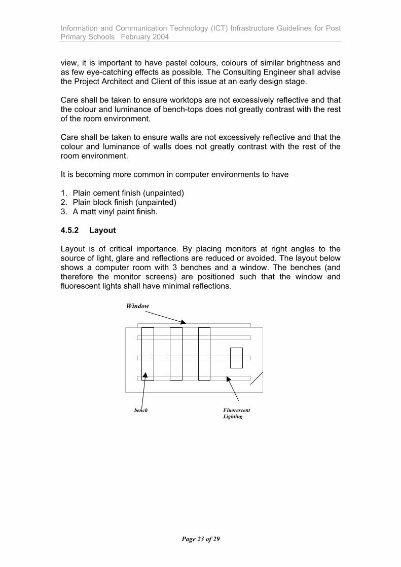
Information and Communication Technology (ICT) Infrastructure Guidelines for Post Primary Schools February 2004 view, it is important to have pastel colours, colours of similar brightness and as few eye-catching effects as possible. The Consulting Engineer shall advise the Project Architect and Client of this issue at an early design stage. Care shall be taken to ensure worktops are not excessively reflective and that the colour and luminance of bench-tops does not greatly contrast with the rest of the room environment. Care shall be taken to ensure walls are not excessively reflective and that the colour and luminance of walls does not greatly contrast with the rest of the room environment. It is becoming more common in computer environments to have 1. Plain cement finish (unpainted) 2. Plain block finish (unpainted) 3. A matt vinyl paint finish. 4.5.2 Layout Layout is of critical importance. By placing monitors at right angles to the source of light, glare and reflections are reduced or avoided. The layout below shows a computer room with 3 benches and a window. The benches (and therefore the monitor screens) are positioned such that the window and fluorescent lights shall have minimal reflections. Window
Fluorescent Lighting
bench
Page 23 of 29
Information and Communication Technology (ICT) Infrastructure Guidelines for Post Primary Schools February 2004 4.5.3 Natural Lighting Windows in Computer rooms shall be designed as “wide and low” rather than “narrow and high” to minimise the area of bright, visible sky. The use of reflective coatings on windows or tinted glass shall generally be discouraged, as they rarely provide a solution in isolation. They may be necessary on existing south facing sections of buildings. On new school design the Computer room shall be located on the north facing elevation. For all but north facing windows, special care must be taken to ensure that direct sunlight can be limited. Night-time effects such as reflectance of internal lighting from windows may also cause problems. 4.5.4 Electric Lighting Lighting designs shall be based on direct lighting (no uplighting). While light levels in specialist rooms shall be 500 lux, a light level of 300 lux is satisfactory in computer rooms. Luminaries shall be high frequency linear fluorescent lighting. A luminance limit of 200cd/m2 at 65o elevation shall be provided in computer rooms in accordance with EN 12464-1:2002. In the computer room automatic lighting controls shall be based on manual on / off switching, absence detection and daylight sensing, so that lights will need to be switched on manually and will then dim/ turn off automatically depending on the signals from the automatic controls.
Page 24 of 29
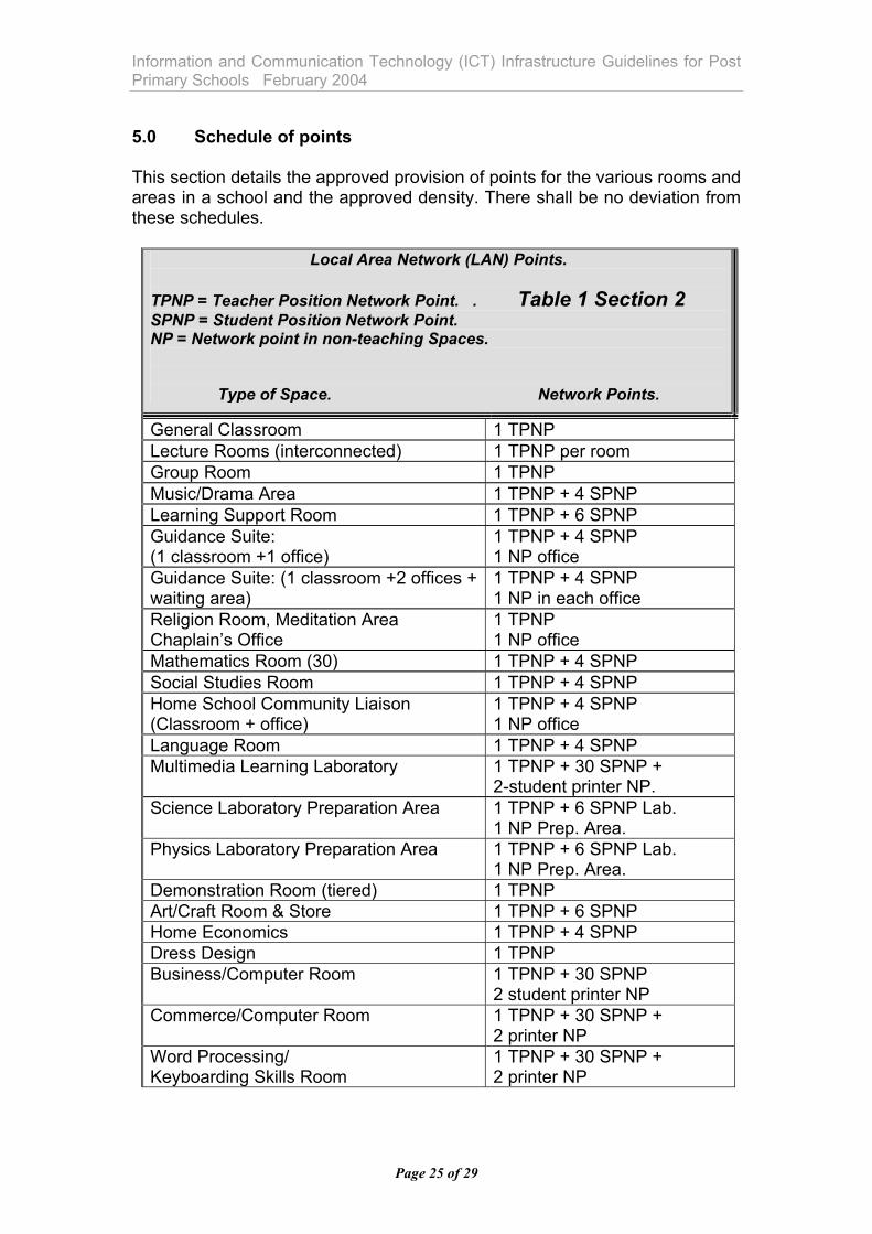
Information and Communication Technology (ICT) Infrastructure Guidelines for Post Primary Schools February 2004 5.0 Schedule of points This section details the approved provision of points for the various rooms and areas in a school and the approved density. There shall be no deviation from these schedules.
Local Area Network (LAN) Points. TPNP = Teacher Position Network Point. . Table 1 Section 2 SPNP = Student Position Network Point. NP = Network point in non-teaching Spaces.
Type of Space. Network Points.
General Classroom 1 TPNP Lecture Rooms (interconnected) 1 TPNP per room Group Room 1 TPNP Music/Drama Area 1 TPNP + 4 SPNP Learning Support Room 1 TPNP + 6 SPNP Guidance Suite: (1 classroom +1 office)
1 TPNP + 4 SPNP 1 NP office
Guidance Suite: (1 classroom +2 offices + waiting area)
1 TPNP + 4 SPNP 1 NP in each office
Religion Room, Meditation Area Chaplain’s Office
1 TPNP 1 NP office
Mathematics Room (30) 1 TPNP + 4 SPNP Social Studies Room 1 TPNP + 4 SPNP Home School Community Liaison (Classroom + office)
1 TPNP + 4 SPNP 1 NP office
Language Room 1 TPNP + 4 SPNP Multimedia Learning Laboratory 1 TPNP + 30 SPNP +
2-student printer NP. Science Laboratory Preparation Area 1 TPNP + 6 SPNP Lab.
1 NP Prep. Area. Physics Laboratory Preparation Area 1 TPNP + 6 SPNP Lab.
1 NP Prep. Area. Demonstration Room (tiered) 1 TPNP Art/Craft Room & Store 1 TPNP + 6 SPNP Home Economics 1 TPNP + 4 SPNP Dress Design 1 TPNP Business/Computer Room 1 TPNP + 30 SPNP
2 student printer NP Commerce/Computer Room 1 TPNP + 30 SPNP +
2 printer NP Word Processing/ Keyboarding Skills Room
1 TPNP + 30 SPNP + 2 printer NP
Page 25 of 29
Information and Communication Technology (ICT) Infrastructure Guidelines for Post Primary Schools February 2004
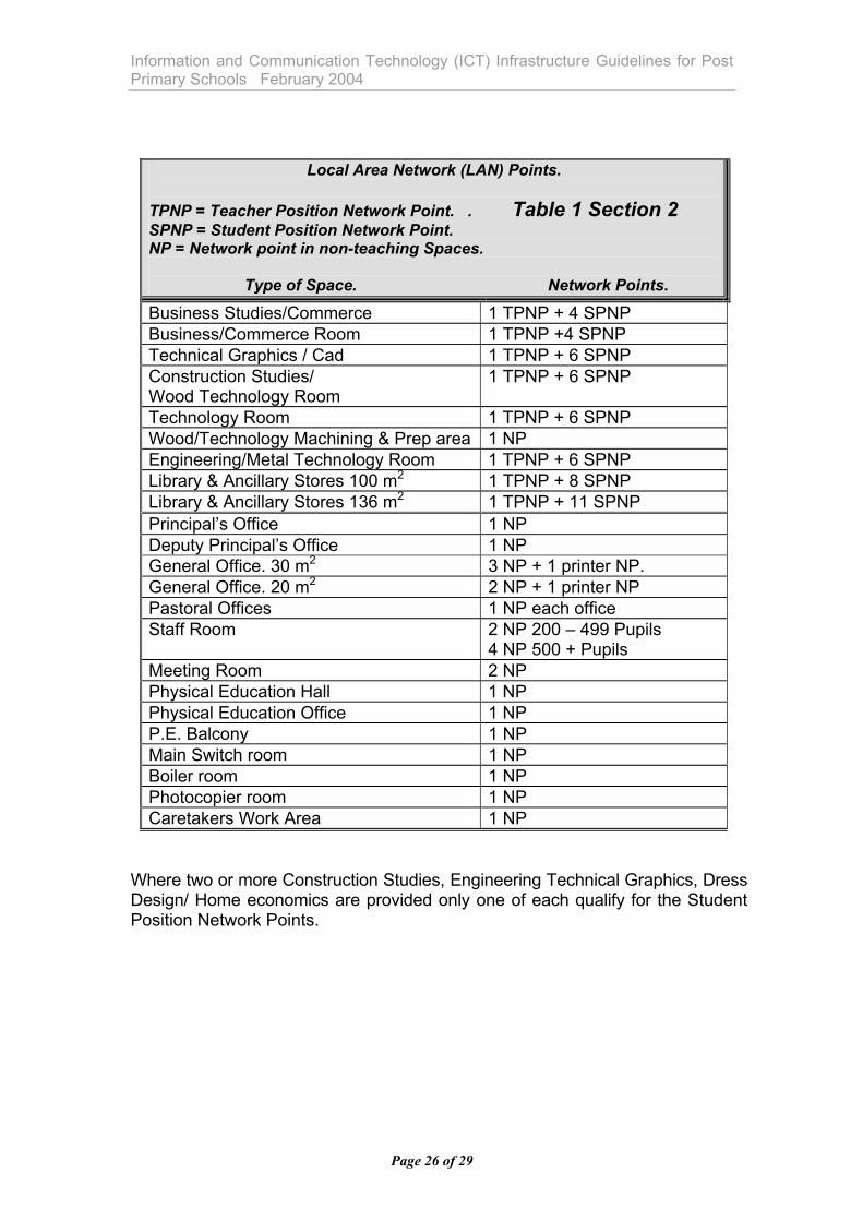
Local Area Network (LAN) Points. TPNP = Teacher Position Network Point. . Table 1 Section 2 SPNP = Student Position Network Point. NP = Network point in non-teaching Spaces.
Type of Space. Network Points.
Business Studies/Commerce 1 TPNP + 4 SPNP Business/Commerce Room 1 TPNP +4 SPNP Technical Graphics / Cad 1 TPNP + 6 SPNP Construction Studies/ Wood Technology Room
1 TPNP + 6 SPNP
Technology Room 1 TPNP + 6 SPNP Wood/Technology Machining & Prep area 1 NP Engineering/Metal Technology Room 1 TPNP + 6 SPNP Library & Ancillary Stores 100 m2 1 TPNP + 8 SPNP Library & Ancillary Stores 136 m2 1 TPNP + 11 SPNP Principal’s Office 1 NP Deputy Principal’s Office 1 NP General Office. 30 m2 3 NP + 1 printer NP. General Office. 20 m2 2 NP + 1 printer NP Pastoral Offices 1 NP each office Staff Room 2 NP 200 – 499 Pupils
4 NP 500 + Pupils Meeting Room 2 NP Physical Education Hall 1 NP Physical Education Office 1 NP P.E. Balcony 1 NP Main Switch room 1 NP Boiler room 1 NP Photocopier room 1 NP Caretakers Work Area 1 NP
Where two or more Construction Studies, Engineering Technical Graphics, Dress Design/ Home economics are provided only one of each qualify for the Student Position Network Points.
Page 26 of 29
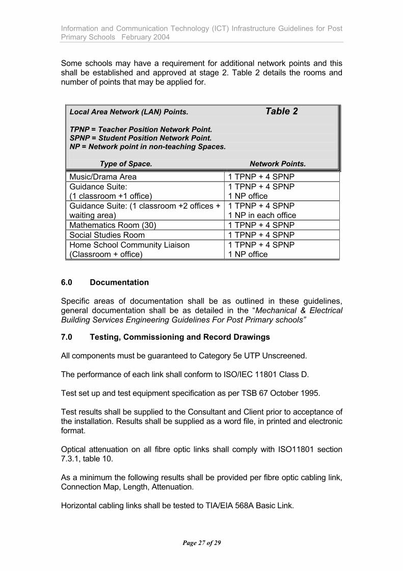
Information and Communication Technology (ICT) Infrastructure Guidelines for Post Primary Schools February 2004 Some schools may have a requirement for additional network points and this shall be established and approved at stage 2. Table 2 details the rooms and number of points that may be applied for.
Local Area Network (LAN) Points. Table 2 TPNP = Teacher Position Network Point. SPNP = Student Position Network Point. NP = Network point in non-teaching Spaces.
Type of Space. Network Points.
Music/Drama Area 1 TPNP + 4 SPNP Guidance Suite: (1 classroom +1 office)
1 TPNP + 4 SPNP 1 NP office
Guidance Suite: (1 classroom +2 offices + waiting area)
1 TPNP + 4 SPNP 1 NP in each office
Mathematics Room (30) 1 TPNP + 4 SPNP Social Studies Room 1 TPNP + 4 SPNP Home School Community Liaison (Classroom + office)
1 TPNP + 4 SPNP 1 NP office
6.0 Documentation Specific areas of documentation shall be as outlined in these guidelines, general documentation shall be as detailed in the “Mechanical & Electrical Building Services Engineering Guidelines For Post Primary schools” 7.0 Testing, Commissioning and Record Drawings All components must be guaranteed to Category 5e UTP Unscreened. The performance of each link shall conform to ISO/IEC 11801 Class D. Test set up and test equipment specification as per TSB 67 October 1995. Test results shall be supplied to the Consultant and Client prior to acceptance of the installation. Results shall be supplied as a word file, in printed and electronic format. Optical attenuation on all fibre optic links shall comply with ISO11801 section 7.3.1, table 10. As a minimum the following results shall be provided per fibre optic cabling link, Connection Map, Length, Attenuation. Horizontal cabling links shall be tested to TIA/EIA 568A Basic Link.
Page 27 of 29

Information and Communication Technology (ICT) Infrastructure Guidelines for Post Primary Schools February 2004 As a minimum the following results shall be provided in a link performance certificate per horizontal cabling link:
Connection Map Length (or propagation delay) DC loop resistance/Pair Capacitance per pair Attenuation per pair (0-100MHZ) Near End Cross Talk NEXT per each pair combination (0-100MHZ) ACR per pair.
On completion, the supplier shall provide full test results in a bound paper form, and in an electronic format on disk and also provide ‘as installed’ drawings with floor plans, wire charts, cable paths, upgrade routes in AutoCAD 14 or latest edition as detailed above. 8.0 Training and Demonstration
After the Building Services Consulting Engineer is satisfied and has witnessed that all equipment and systems are operating satisfactory, training and demonstration shall take place. Adequate notice shall be given to the Client and, at an agreed time and in the presence of the Building Services Consulting Engineer, a training and demonstration event shall be provided.
Page 28 of 29

Information and Communication Technology (ICT) Infrastructure Guidelines for Post Primary Schools February 2004
Page 29 of 29
Appendix A Completion Record Sheet
School Name: Address Project: Signatures & Date Information and Communication Technology Infrastructure, installed, tested and operating satisfactorily.
Operating & Maintenance Manuals handed over to School and explained.
Training and demonstration meeting held in the presence of the Building Services Consulting Engineer and School Caretaker and Principal.
Date
Wall Chart provided, explaining common operating / maintenance procedures.
As installed Drawings handed over to school in hard copy and on disc.
School Principal Name:
Signed:
Date:
Building Services Consulting Engineers Name:
Signed:
Date: