Embed Size (px)
Citation preview
Accepted Manuscript
Title: Influence of tool shoulder geometry on properties offriction stir welds in thin copper sheets
Authors: I. Galvao, R.M. Leal, D.M. Rodrigues, A. Loureiro
PII: S0924-0136(12)00280-4DOI: doi:10.1016/j.jmatprotec.2012.09.016Reference: PROTEC 13516
To appear in: Journal of Materials Processing Technology
Received date: 8-3-2012Revised date: 24-7-2012Accepted date: 24-9-2012
Please cite this article as: Galvao, I., Leal, R.M., Rodrigues, D.M., Loureiro,A., INFLUENCE OF TOOL SHOULDER GEOMETRY ON PROPERTIES OFFRICTION STIR WELDS IN THIN COPPER SHEETS, Journal of MaterialsProcessing Technology (2010), doi:10.1016/j.jmatprotec.2012.09.016
This is a PDF file of an unedited manuscript that has been accepted for publication.As a service to our customers we are providing this early version of the manuscript.The manuscript will undergo copyediting, typesetting, and review of the resulting proofbefore it is published in its final form. Please note that during the production processerrors may be discovered which could affect the content, and all legal disclaimers thatapply to the journal pertain.
Page 1 of 23
Accep
ted
Man
uscr
ipt
1
HIGHLIGHTS
Flat shoulder tool is inadequate for performing copper friction stir welds;
Scrolled shoulder provides the largest range of non-defective welds;
Scrolled shoulder provides welds with finer grain structure and higher strength;
Conical and scrolled shoulders require a minimum rotational speed to avoid defects.
Page 2 of 23
Accep
ted
Man
uscr
ipt
2
INFLUENCE OF TOOL SHOULDER GEOMETRY ON PROPERTIES OF FRICTION
STIR WELDS IN THIN COPPER SHEETS
I. Galvão 1, R.M. Leal 1, 2, D.M. Rodrigues 1, A. Loureiro 1,*
1 - CEMUC, Department of Mechanical Engineering, University of Coimbra, Rua Luís Reis Santos,
3030-788 Coimbra, Portugal
2 - ESAD.CR, Polytechnic Institute of Leiria, Rua Isidoro Inácio Alves de Carvalho, 2500-321
Caldas da Rainha, Portugal
* e-mail: [email protected], tel. + (351) 239 790 700, fax. + (351) 239 790 701
Page 3 of 23
Accep
ted
Man
uscr
ipt
3
ABSTRACT
The aim of this work is to study the influence of the shoulder geometry on friction stir welding of 1
mm-thick copper-DHP plates. The welds were produced using three different shoulder geometries,
flat, conical and scrolled, and varying the rotation and traverse speeds of the tool. The flat shoulder
tool proved to be inadequate for performing welds, because many defects were produced for all
welding conditions. In turn, the scrolled shoulder tool is more effective than the conical one in the
production of defect free welds. However, both geometries required a minimum rotational speed to
avoid internal defects. For the same welding parameters, greater grain refinement, higher hardness
and improved strength are also achieved in the nugget of the welds, using the scrolled tool.
Keywords: Friction Stir Welding; Shoulder geometry; Microstructure; Mechanical properties;
Copper.
INTRODUCTION
Although many researchers recognize that tool geometry is a fundamental parameter in the friction
stir welding (FSW) process, the knowledge of its influence on heat generation, material flow and
the properties of the welds is still limited (Nandan et al., 2008). In fact, as the geometry of the tools
is complex and difficult to characterize, most of the studies consider the effect of the tool shoulder
and pin separately, as in Zao et al. (2006) and Leal et al. (2008). As it is well-known, the basic
functions of the tool are to generate heat, in order to plasticize the material, and to direct the flow of
plasticized material, preventing the formation of defects. In particular, the tool pin plays an
important role in the flow of material in the thickness direction, especially in thick plates. This way,
in recent years, instead of the traditional cylindrical or conical threaded pins, tools with pins of
complex geometry have been developed, as showed by Thomas et al. (2003). Fuller (2007) and Rai
Page 4 of 23
Accep
ted
Man
uscr
ipt
4
et al. (2011) summarize very well the tool geometries developed in recent years as well their effects
on the welding process. The virtues attributed to these complex geometries are related to the
increased flow of material in the thickness direction as well as to higher heat generation due to the
increased interface area between the tool and the workpiece. However, Schmidt et al. (2004)
developed an analytical model for a tool with a conical shoulder and cylindrical pin, which showed
that most of the heat is generated by the shoulder and only about 14% is generated by the pin.
Moreover, Mehta et al. (2011), on FSW in 7075-T6 alloy, pointed out that the heat generated
increases with increasing shoulder diameter. These authors also stated that the optimum diameter is
a function of the tool’s rotation speed.
Dawes and Thomas (1999), in a further shoulder geometry study, showed that the use of a
scrolled-shoulder tool allows welds in aluminum alloys to be produced without tool tilting, which
besides improving the surface finishing and the mechanical properties of the welds, allows higher
welding speeds. Although this study was published in 1999, only few recent studies, such as Scialpi
et al. (2008), Gratecap et al. (2008) and Leal et al. (2011), have addressed the influence of the
shoulder geometry on the quality of friction stir welds, particularly in reduced thickness welds,
where material flow is more constrained due to the cooling effect of the backing plate.
Copper and alloys, although expensive, have great potential to be used in industry due to their
high electrical and thermal conductivities and excellent corrosion resistance. As mentioned by
McNelley et al. (2007) and Cederqvist et al. (2009), they are used for components in a wide range
of marine systems and, for example, for the encapsulation of nuclear waste material. However,
copper alloys are difficult to weld by fusion because adherent oxides inhibit welding, or volatile and
toxic elements, such as zinc, may be present in the alloys, requiring adequate ventilation. Therefore,
FSW is a good option for joining parts made of these materials. The optimization of FSW tool
geometry and process parameters is still required. To this end, the current study addresses the effect
of tool shoulder geometry on the microstructure and mechanical properties of friction stir welds in
Page 5 of 23
Accep
ted
Man
uscr
ipt
5
thin copper sheets. The effect of shoulder geometry on the heat generated in the process is also
discussed.
EXPERIMENTAL PROCEDURE
Copper plates, 1 mm-thick and 250 mm-long, were butt joined by friction stir welding. The base
material was deoxidized copper (copper-DHP), temper class R240, with a grain size of 18 µm and
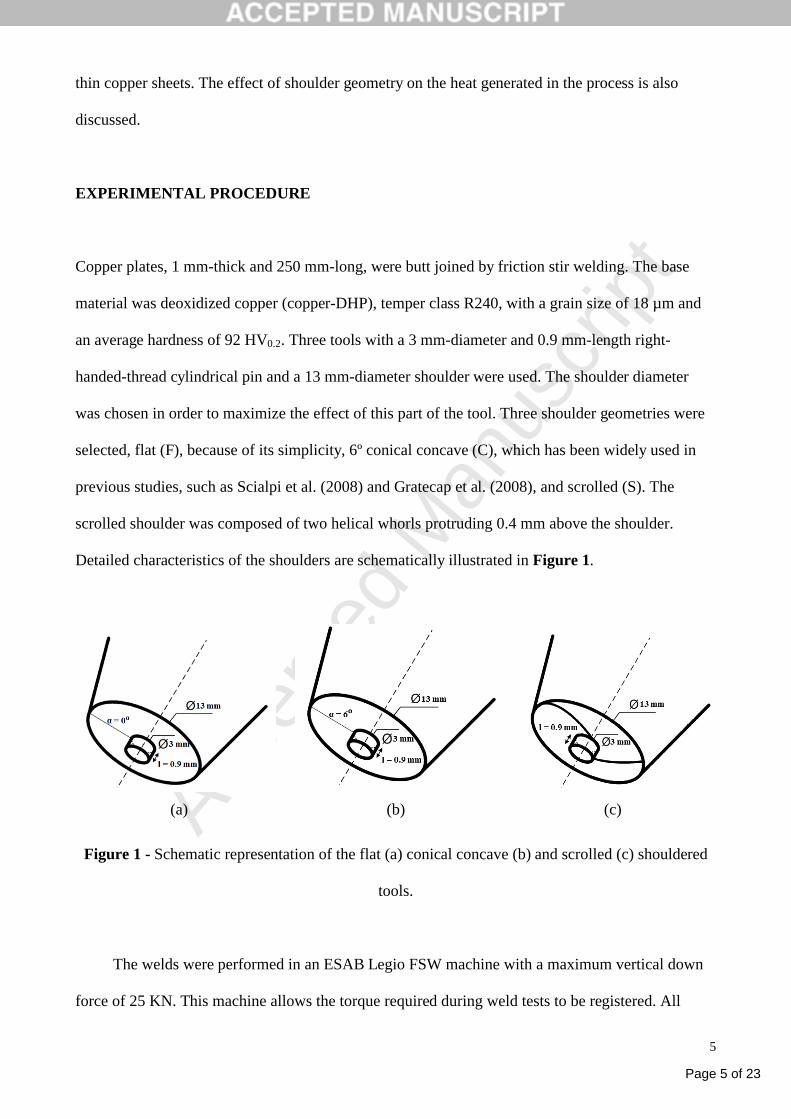
an average hardness of 92 HV0.2. Three tools with a 3 mm-diameter and 0.9 mm-length right-
handed-thread cylindrical pin and a 13 mm-diameter shoulder were used. The shoulder diameter
was chosen in order to maximize the effect of this part of the tool. Three shoulder geometries were
selected, flat (F), because of its simplicity, 6º conical concave (C), which has been widely used in
previous studies, such as Scialpi et al. (2008) and Gratecap et al. (2008), and scrolled (S). The
scrolled shoulder was composed of two helical whorls protruding 0.4 mm above the shoulder.
Detailed characteristics of the shoulders are schematically illustrated in Figure 1.
(a) (b) (c)
Figure 1 - Schematic representation of the flat (a) conical concave (b) and scrolled (c) shouldered
tools.
The welds were performed in an ESAB Legio FSW machine with a maximum vertical down
force of 25 KN. This machine allows the torque required during weld tests to be registered. All
Page 6 of 23
Accep
ted
Man
uscr
ipt
6
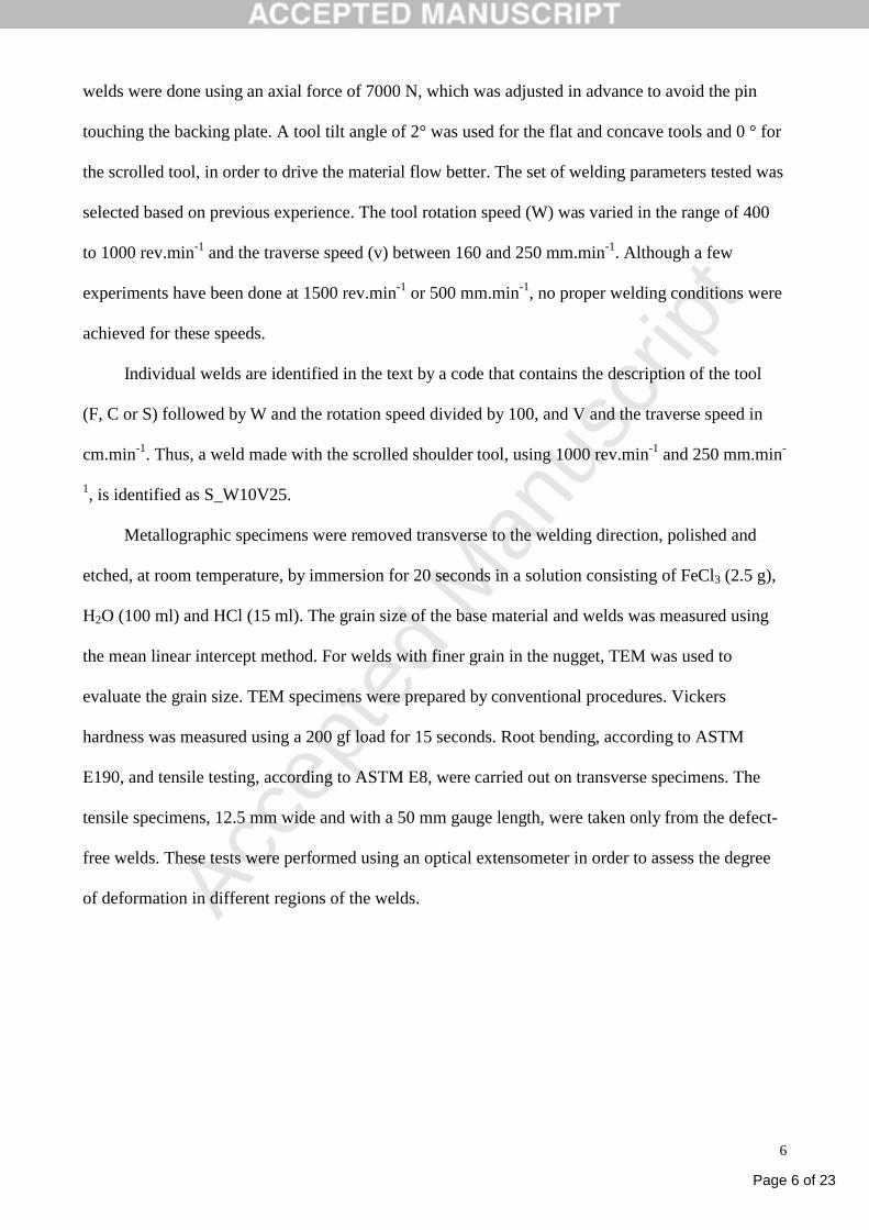
welds were done using an axial force of 7000 N, which was adjusted in advance to avoid the pin
touching the backing plate. A tool tilt angle of 2° was used for the flat and concave tools and 0 ° for
the scrolled tool, in order to drive the material flow better. The set of welding parameters tested was
selected based on previous experience. The tool rotation speed (W) was varied in the range of 400
to 1000 rev.min-1 and the traverse speed (v) between 160 and 250 mm.min-1. Although a few
experiments have been done at 1500 rev.min-1 or 500 mm.min-1, no proper welding conditions were
achieved for these speeds.
Individual welds are identified in the text by a code that contains the description of the tool
(F, C or S) followed by W and the rotation speed divided by 100, and V and the traverse speed in
cm.min-1. Thus, a weld made with the scrolled shoulder tool, using 1000 rev.min-1 and 250 mm.min-
1, is identified as S_W10V25.
Metallographic specimens were removed transverse to the welding direction, polished and
etched, at room temperature, by immersion for 20 seconds in a solution consisting of FeCl3 (2.5 g),
H2O (100 ml) and HCl (15 ml). The grain size of the base material and welds was measured using
the mean linear intercept method. For welds with finer grain in the nugget, TEM was used to
evaluate the grain size. TEM specimens were prepared by conventional procedures. Vickers
hardness was measured using a 200 gf load for 15 seconds. Root bending, according to ASTM
E190, and tensile testing, according to ASTM E8, were carried out on transverse specimens. The
tensile specimens, 12.5 mm wide and with a 50 mm gauge length, were taken only from the defect-
free welds. These tests were performed using an optical extensometer in order to assess the degree
of deformation in different regions of the welds.
Page 7 of 23
Accep
ted
Man
uscr
ipt
7
RESULTS
Welds Morphology
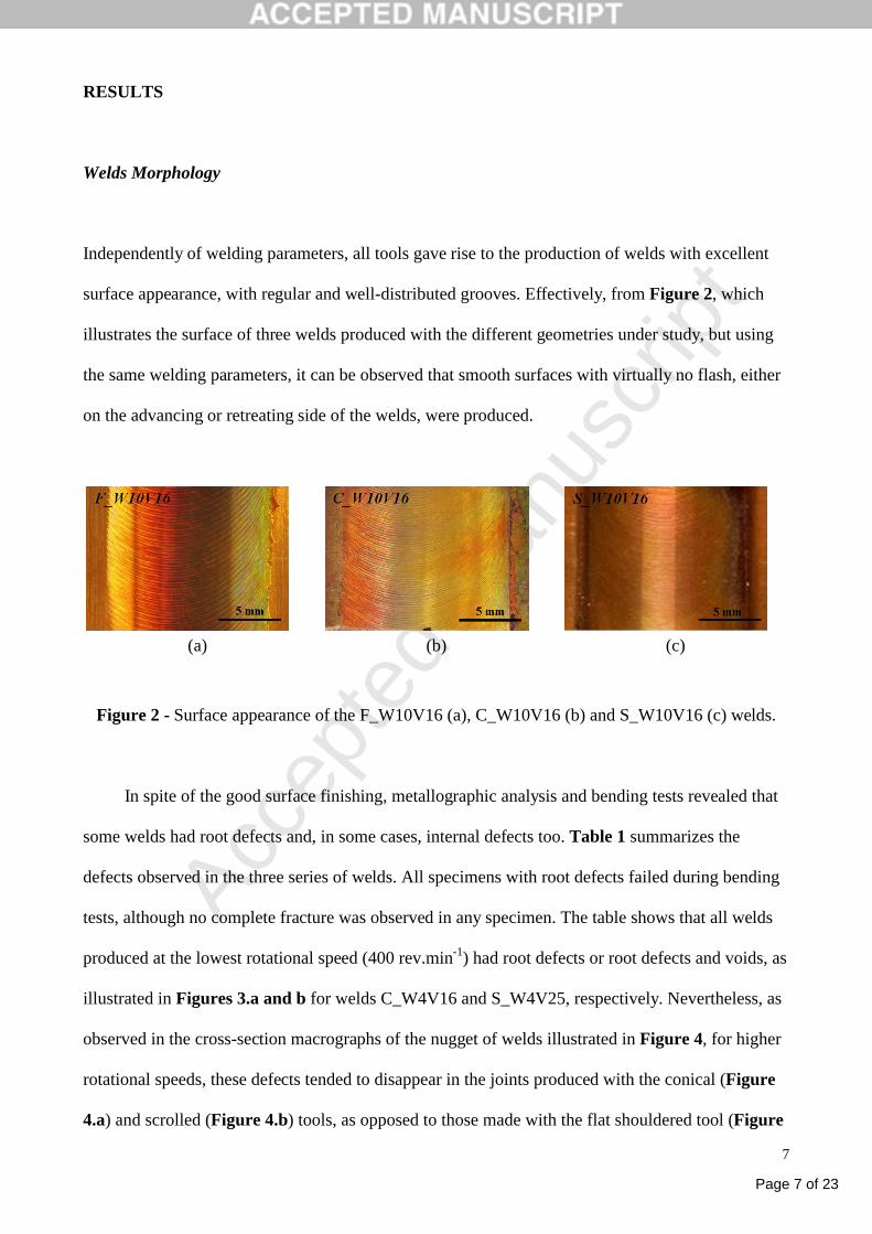
Independently of welding parameters, all tools gave rise to the production of welds with excellent
surface appearance, with regular and well-distributed grooves. Effectively, from Figure 2, which
illustrates the surface of three welds produced with the different geometries under study, but using
the same welding parameters, it can be observed that smooth surfaces with virtually no flash, either
on the advancing or retreating side of the welds, were produced.
(a) (b) (c)
Figure 2 - Surface appearance of the F_W10V16 (a), C_W10V16 (b) and S_W10V16 (c) welds.
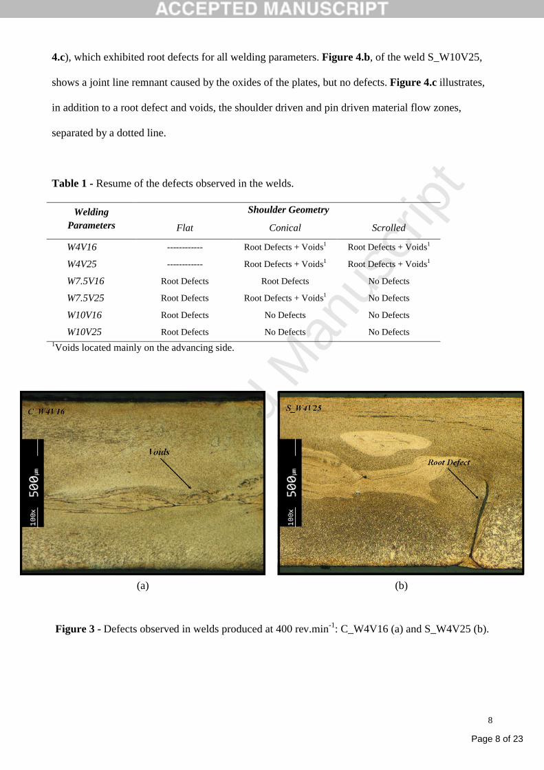
In spite of the good surface finishing, metallographic analysis and bending tests revealed that
some welds had root defects and, in some cases, internal defects too. Table 1 summarizes the
defects observed in the three series of welds. All specimens with root defects failed during bending
tests, although no complete fracture was observed in any specimen. The table shows that all welds
produced at the lowest rotational speed (400 rev.min-1) had root defects or root defects and voids, as
illustrated in Figures 3.a and b for welds C_W4V16 and S_W4V25, respectively. Nevertheless, as
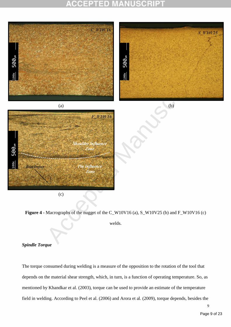
observed in the cross-section macrographs of the nugget of welds illustrated in Figure 4, for higher
rotational speeds, these defects tended to disappear in the joints produced with the conical (Figure
4.a) and scrolled (Figure 4.b) tools, as opposed to those made with the flat shouldered tool (Figure
Page 8 of 23
Accep
ted
Man
uscr
ipt
8
4.c), which exhibited root defects for all welding parameters. Figure 4.b, of the weld S_W10V25,
shows a joint line remnant caused by the oxides of the plates, but no defects. Figure 4.c illustrates,
in addition to a root defect and voids, the shoulder driven and pin driven material flow zones,
separated by a dotted line.
Table 1 - Resume of the defects observed in the welds.
Shoulder GeometryWelding Parameters Flat Conical Scrolled
W4V16 ------------ Root Defects + Voids1 Root Defects + Voids1
W4V25 ------------ Root Defects + Voids1 Root Defects + Voids1
W7.5V16 Root Defects Root Defects No Defects
W7.5V25 Root Defects Root Defects + Voids1 No Defects
W10V16 Root Defects No Defects No Defects
W10V25 Root Defects No Defects No Defects1Voids located mainly on the advancing side.
(a) (b)
Figure 3 - Defects observed in welds produced at 400 rev.min-1: C_W4V16 (a) and S_W4V25 (b).
Page 9 of 23
Accep
ted
Man
uscr
ipt
9
(a) (b)
(c)
Figure 4 - Macrographs of the nugget of the C_W10V16 (a), S_W10V25 (b) and F_W10V16 (c)
welds.
Spindle Torque
The torque consumed during welding is a measure of the opposition to the rotation of the tool that
depends on the material shear strength, which, in turn, is a function of operating temperature. So, as
mentioned by Khandkar et al. (2003), torque can be used to provide an estimate of the temperature
field in welding. According to Peel et al. (2006) and Arora et al. (2009), torque depends, besides the
Page 10 of 23
Accep
ted
Man
uscr
ipt
10
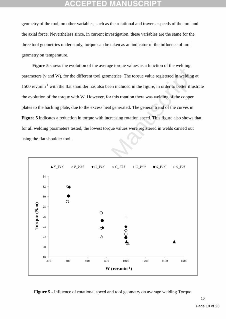
geometry of the tool, on other variables, such as the rotational and traverse speeds of the tool and
the axial force. Nevertheless since, in current investigation, these variables are the same for the
three tool geometries under study, torque can be taken as an indicator of the influence of tool
geometry on temperature.
Figure 5 shows the evolution of the average torque values as a function of the welding
parameters (v and W), for the different tool geometries. The torque value registered in welding at
1500 rev.min-1 with the flat shoulder has also been included in the figure, in order to better illustrate
the evolution of the torque with W. However, for this rotation there was welding of the copper
plates to the backing plate, due to the excess heat generated. The general trend of the curves in
Figure 5 indicates a reduction in torque with increasing rotation speed. This figure also shows that,
for all welding parameters tested, the lowest torque values were registered in welds carried out
using the flat shoulder tool.
Figure 5 - Influence of rotational speed and tool geometry on average welding Torque.
Page 11 of 23
Accep
ted
Man
uscr
ipt
11
Microstructure and Mechanical Properties
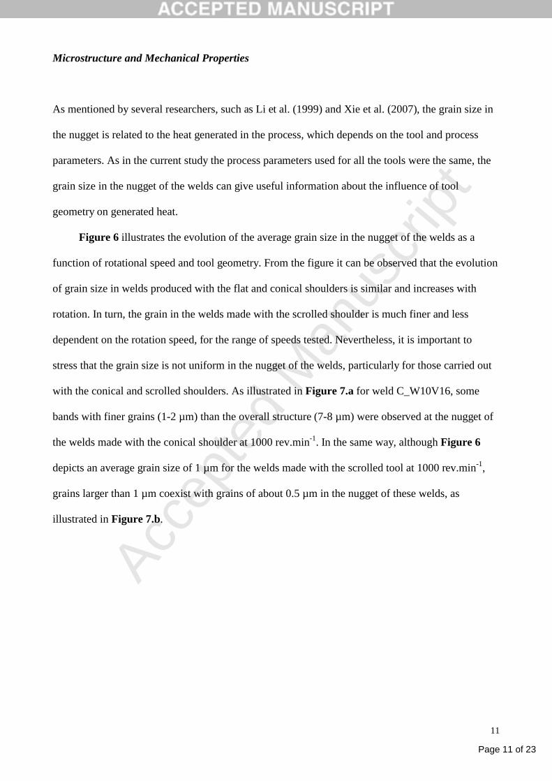
As mentioned by several researchers, such as Li et al. (1999) and Xie et al. (2007), the grain size in
the nugget is related to the heat generated in the process, which depends on the tool and process
parameters. As in the current study the process parameters used for all the tools were the same, the
grain size in the nugget of the welds can give useful information about the influence of tool
geometry on generated heat.
Figure 6 illustrates the evolution of the average grain size in the nugget of the welds as a
function of rotational speed and tool geometry. From the figure it can be observed that the evolution
of grain size in welds produced with the flat and conical shoulders is similar and increases with
rotation. In turn, the grain in the welds made with the scrolled shoulder is much finer and less
dependent on the rotation speed, for the range of speeds tested. Nevertheless, it is important to
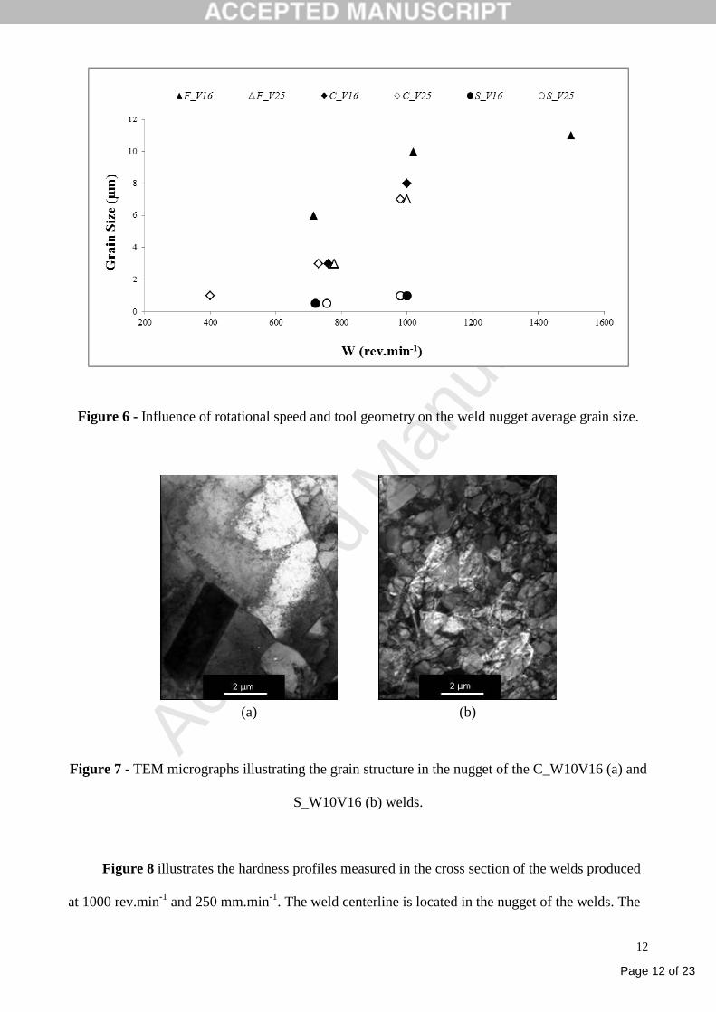
stress that the grain size is not uniform in the nugget of the welds, particularly for those carried out
with the conical and scrolled shoulders. As illustrated in Figure 7.a for weld C_W10V16, some
bands with finer grains (1-2 µm) than the overall structure (7-8 µm) were observed at the nugget of
the welds made with the conical shoulder at 1000 rev.min-1. In the same way, although Figure 6
depicts an average grain size of 1 µm for the welds made with the scrolled tool at 1000 rev.min-1,
grains larger than 1 µm coexist with grains of about 0.5 µm in the nugget of these welds, as
illustrated in Figure 7.b.
Page 12 of 23
Accep
ted
Man
uscr
ipt
12
Figure 6 - Influence of rotational speed and tool geometry on the weld nugget average grain size.
(a) (b)
Figure 7 - TEM micrographs illustrating the grain structure in the nugget of the C_W10V16 (a) and
S_W10V16 (b) welds.
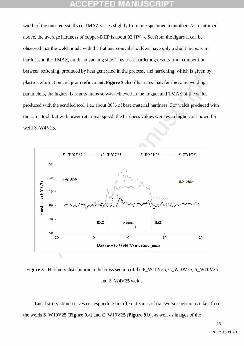
Figure 8 illustrates the hardness profiles measured in the cross section of the welds produced
at 1000 rev.min-1 and 250 mm.min-1. The weld centerline is located in the nugget of the welds. The
Page 13 of 23
Accep
ted
Man
uscr
ipt
13
width of the non-recrystallized TMAZ varies slightly from one specimen to another. As mentioned
above, the average hardness of copper-DHP is about 92 HV0.2. So, from the figure it can be
observed that the welds made with the flat and conical shoulders have only a slight increase in
hardness in the TMAZ, on the advancing side. This local hardening results from competition
between softening, produced by heat generated in the process, and hardening, which is given by
plastic deformation and grain refinement. Figure 8 also illustrates that, for the same welding
parameters, the highest hardness increase was achieved in the nugget and TMAZ of the welds
produced with the scrolled tool, i.e., about 30% of base material hardness. For welds produced with
the same tool, but with lower rotational speed, the hardness values were even higher, as shown for
weld S_W4V25.
Figure 8 - Hardness distribution in the cross section of the F_W10V25, C_W10V25, S_W10V25
and S_W4V25 welds.
Local stress-strain curves corresponding to different zones of transverse specimens taken from
the welds S_W10V25 (Figure 9.a) and C_W10V25 (Figure 9.b), as well as images of the
Page 14 of 23
Accep
ted
Man
uscr
ipt
14
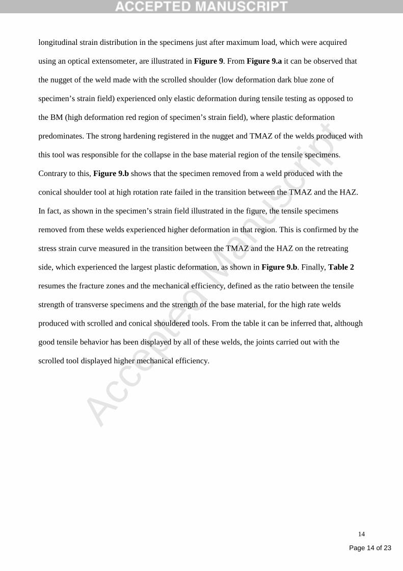
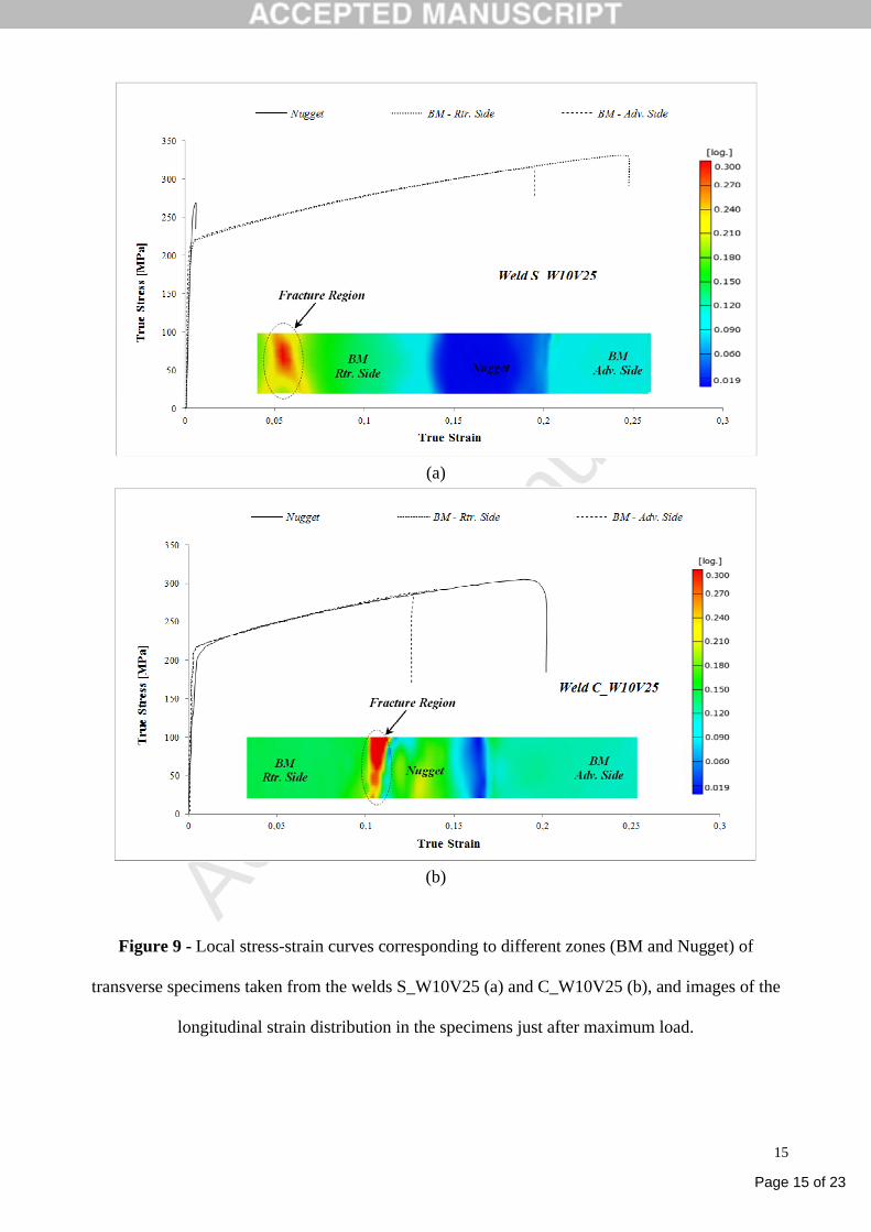
longitudinal strain distribution in the specimens just after maximum load, which were acquired
using an optical extensometer, are illustrated in Figure 9. From Figure 9.a it can be observed that
the nugget of the weld made with the scrolled shoulder (low deformation dark blue zone of
specimen’s strain field) experienced only elastic deformation during tensile testing as opposed to
the BM (high deformation red region of specimen’s strain field), where plastic deformation
predominates. The strong hardening registered in the nugget and TMAZ of the welds produced with
this tool was responsible for the collapse in the base material region of the tensile specimens.
Contrary to this, Figure 9.b shows that the specimen removed from a weld produced with the
conical shoulder tool at high rotation rate failed in the transition between the TMAZ and the HAZ.
In fact, as shown in the specimen’s strain field illustrated in the figure, the tensile specimens
removed from these welds experienced higher deformation in that region. This is confirmed by the
stress strain curve measured in the transition between the TMAZ and the HAZ on the retreating
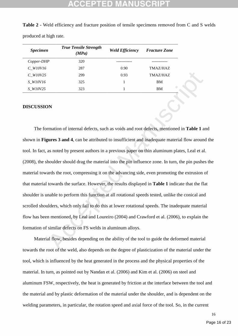
side, which experienced the largest plastic deformation, as shown in Figure 9.b. Finally, Table 2
resumes the fracture zones and the mechanical efficiency, defined as the ratio between the tensile
strength of transverse specimens and the strength of the base material, for the high rate welds
produced with scrolled and conical shouldered tools. From the table it can be inferred that, although
good tensile behavior has been displayed by all of these welds, the joints carried out with the
scrolled tool displayed higher mechanical efficiency.
Page 15 of 23
Accep
ted
Man
uscr
ipt
15
(a)
(b)
Figure 9 - Local stress-strain curves corresponding to different zones (BM and Nugget) of
transverse specimens taken from the welds S_W10V25 (a) and C_W10V25 (b), and images of the
longitudinal strain distribution in the specimens just after maximum load.
Page 16 of 23
Accep
ted
Man
uscr
ipt
16
Table 2 - Weld efficiency and fracture position of tensile specimens removed from C and S welds
produced at high rate.
SpecimenTrue Tensile Strength
(MPa)Weld Efficiency Fracture Zone
Copper-DHP 320 ------------ ------------
C_W10V16 287 0.90 TMAZ/HAZ
C_W10V25 299 0.93 TMAZ/HAZ
S_W10V16 325 1 BM
S_W10V25 323 1 BM
DISCUSSION
The formation of internal defects, such as voids and root defects, mentioned in Table 1 and
shown in Figures 3 and 4, can be attributed to insufficient and inadequate material flow around the
tool. In fact, as noted by present authors in a previous paper on thin aluminum plates, Leal et al.
(2008), the shoulder should drag the material into the pin influence zone. In turn, the pin pushes the
material towards the root, compressing it on the advancing side, even promoting the extrusion of
that material towards the surface. However, the results displayed in Table 1 indicate that the flat
shoulder is unable to perform this function at all rotational speeds tested, unlike the conical and
scrolled shoulders, which only fail to do this at lower rotational speeds. The inadequate material
flow has been mentioned, by Leal and Loureiro (2004) and Crawford et al. (2006), to explain the
formation of similar defects on FS welds in aluminum alloys.
Material flow, besides depending on the ability of the tool to guide the deformed material
towards the root of the weld, also depends on the degree of plasticization of the material under the
tool, which is influenced by the heat generated in the process and the physical properties of the
material. In turn, as pointed out by Nandan et al. (2006) and Kim et al. (2006) on steel and
aluminum FSW, respectively, the heat is generated by friction at the interface between the tool and
the material and by plastic deformation of the material under the shoulder, and is dependent on the
welding parameters, in particular, the rotation speed and axial force of the tool. So, in the current
Page 17 of 23
Accep
ted
Man
uscr
ipt
17
investigation, the weld defects produced by any of the tools at a speed of 400 rev. min-1 were caused
by insufficient heat to provide good plasticization and proper flow of material.
For higher rotational speeds, the different tools produced welds with different morphologies.
As the parameters (W, v and F) used in the three series of welds were the same, this suggests that
the tool geometries under study generate different amounts of heat or provide material in different
streams in the TMAZ. In fact, whereas welds made with flat and conical shoulders at the speed of
750 rev. min-1 exhibit defects, no defects were identified in the welds performed with the scrolled
shoulder. Nevertheless, the effect of the flat and conical shoulders is not identical, because, as
mentioned above, unlike the latter, the former does not produce sound welds even at the rotation
speed of 1000 rev. min-1 (Table 1 and Figure 4). Although temperatures were not measured in the
weld vicinity, due to the difficulty in fixing thermocouples to such thin plates, those results suggest
that the flat shoulder generates little heat, the conical shoulder generates an intermediate level of
heat and the scrolled shoulder generates the most heat, which favors the plasticization of the
material and its flow around the tool. However, these results contradict those of De Giorgi et al.
(2009), obtained on FSW in 6082 aluminum alloy, using flat, conical and scrolled shoulder tools, all
with fillet at the edge. These authors inferred, based on nugget grain size and TMAZ hardness, that
the most heat was generated by the flat shouldered tool. According to them, progressively less heat
was generated by the scrolled and conical shouldered tools, although the difference was small.
These discrepancies with the results of De Giorgi et al. (2009) may be attributed to differences in
the geometry of the tools used and to the difference in the welded material. However, Biswas and
Mandal (2011), on FSW in aluminum, also found that the flat shoulder provides higher
temperatures than the conical one.
On the other hand, the general decrease of the spindle torque with tool rotation speed, illustrated in
Figure 5, could be due to increased heat generated by the tool, which reduces the shear strength of
the material to be welded. In fact Arora et al. (2009) and Cui et al. (2010) mentioned that heat
generated increased with rotation speed. Analyzing Figure 5, the lowest torque values are
Page 18 of 23
Accep
ted
Man
uscr
ipt
18
registered in welds carried out with the flat shoulder tool, for all welding parameters, which suggest
that it is this tool that generates most heat, producing the maximum shear stress reduction of the
material under the tool. These results are in good agreement with those of De Giorgi et al. (2009),
referred to above. However, a contradiction in the present study can be found by comparing torque
results and the morphology of the welds, i.e., if the flat shoulder generates more heat, it should not
lead to defects, contrary to what was observed in all welds produced with this tool. Furthermore, for
750 rev.min-1, the torque values of the scrolled shoulder are superior to those of the conical
shoulder, which could indicate less heat generation and a greater likelihood of internal defects,
which is precisely the reverse of that displayed in Table 1. In fact, the torque depends not only on
the heat generated, but also on the volume of material swept around by the shoulder during each
revolution, as mentioned by Cui et al. (2010). So, the low torque values measured in the welds
produced with the flat shoulder can be attributed to the limited ability of this tool to drag the base
material, limiting the interaction between the shoulder-driven and pin-driven material streams, as
suggested by Lorrain et al. (2010) and Leal et al. (2008). This can be observed in Figure 4.c, where
a white dotted line marks the separation between the two material streams. So, taking into account
the strong influence on the torque of the volume of material dragged by the tool each revolution, it
can be concluded that a direct relation between the measured torque and the heat generated cannot
be established.
The lower grain size observed in the nugget of the welds produced with the scrolled tool, as
shown in Figure 6, suggests that this geometry generates the lowest heat, which does not agree well
with the distribution of defects in welds, mentioned in Table 1 and discussed earlier. This
discrepancy can be explained by dynamic recrystallization, which is responsible for the formation
of new grains, being a function not only of temperature but also of the amount and rate of
deformation induced in the material by the tool, as pointed out by Hallberg et al. (2010) and
Chashchukina et al. (2011). Furthermore, Leal et al. (2008) have shown, with regard to FSW in 1
mm-thick plates of aluminum alloys that, compared to the conical shoulder, the scrolled geometry
Page 19 of 23
Accep
ted
Man
uscr
ipt
19
induces more significant material flow, as well as a higher amount of plastic deformation in the
welded material. So, as the rate of nucleation of new grains is proportional to the rate of plastic
deformation, higher nucleation points and, consequently, lower grain growth would be expected in
the nugget of the welds produced with the scrolled tool. Nevertheless, it is also reasonable that
lower heat generation takes place in the welds produced with this tool geometry. In fact, the
prominent striations contained in the shoulder, which penetrate and drag the material during
rotation, can provide a situation identical to sticking material to the tool, in which heat is generated
mainly by plastic deformation, as described by Schmidt et al. (2004). There is further support for
the current results in the literature. Biswas and Mandal (2011) stated that friction gives the largest
contribution to the heat generation in the process and plastic deformation has only a marginal
contribution to make. In conclusion the higher grain refinement observed in welds produced with
the scrolled shoulder tool is very affected by the larger material flow rate induced by this tool,
although the lowest possible heat generated also contributes to the refinement. The higher volume
of material dragged by the scrolled shoulder, which provides material flow through thickness, as
suggested by Figure 4.b where no separation between shoulder driven and pin driven zones can be
observed, explains the tendency of the scrolled shoulder tool to produce defect free welds. The
authors have already proved for FSW in aluminum alloys that the scrolled shoulder favors material
flow throughout the thickness of the weld (Leal et al., 2008).
The grain refinement produced by scrolled shoulder increased the hardness and mechanical
efficiency of these welds relative to those done with a conical concave or flat shoulder. These
results are in accordance with those of Xie et al. (2007), which were obtained from the FSW of pure
copper.
Page 20 of 23
Accep
ted
Man
uscr
ipt
20
CONCLUSIONS
This investigation aimed to study the influence of the shoulder geometry on friction stir welding of
1 mm-thick copper-DHP plates. The following conclusions could be drawn from the experimental
results:
- The flat shoulder tool requires lower weld spindle torque than conical or scrolled shoulder tools.
- The scrolled shoulder tool provides the most suitable material flow and the flat shoulder the worst,
producing only defective welds.
- The scrolled shoulder provides greater grain refinement in the nugget of the welds than the conical
or flat shoulders.
- That refinement is responsible for the increased hardness and mechanical strength of the welds
made with this tool.
ACKNOWLEDGEMENTS
The authors are indebted to the Portuguese Foundation for the Science and Technology (FCT)
through the COMPETE program from QREN, to European Regional Development Fund (ERDF),
for the financial support, and to company Thyssen Portugal – Aços e Serviços Lda, for providing
materials and heat treatments for the friction stir welding tools. The authors are also indebted to the
Technical University of Lisbon for their support in welds production.
Page 21 of 23
Accep
ted
Man
uscr
ipt
21
REFERENCES
Arora, A., Nandan, R., Reynolds, A.P., DebRoy, T., 2009. Torque, power requirement and stir zone
geometry in friction stir welding through modeling and experiments. Scr. Mater. 60, 13-16.
Biswas, P., Mandal, N.R., 2011. Effect of Tool Geometries on Thermal History of FSW of
AA1100. Weld. J. 90, 129-s-135-s.
Cederqvist, L., Sorensen, C.D., Reynolds, A.P., Oberg, T., 2009. Improved process stability during
friction stir welding of 5cm thick copper canisters through shoulder geometry and parameter
studies. Sci. Technol. Weld. Joining 14, 178-184.
Chashchukina, T.I., Voronova, L.M., Degtyarev, M.V., Pokryshkina, D.K., 2011. Deformation and
dynamic recrystallization in copper at different deformation rates in Bridgman anvils. Phys. Met.
Metallogr. 111, 304-313.
Crawford, R., Cook, G.E., Strauss, A.M., Hartman, D.A., Stremler, M.A., 2006. Experimental
defect analysis and force prediction simulation of high weld pitch friction stir welding. Sci.
Technol. Weld. Joining 11, 657-665.
Cui, S., Chen, Z.W., Robson, J.D., 2010. Interrelationships among speeds, torque, and flow
volumes during friction stir welding/processing. In: Proceedings of 8th International Symposium on
Friction Stir Welding, Timmendorfer Strand, Germany.
Dawes, C.J., Thomas, W.M., 1999. Development of improved tool designs for friction stir welding
of aluminium. In: Proceedings of 1st International Symposium on Friction Stir Welding, Thousand
Oaks, California, USA.
De Giorgi, M., Scialpi, A., Panella, F.W., De Filippis, L.A.C., 2009. Effect of shoulder geometry on
residual stress and fatigue properties of AA6082 fsw joints. J. Mech. Sci. Technol. 23, 26-35.
Fuller, C.B, 2007. Friction Stir Tooling: Tool Material and Designs. In: Mishra, R.S., Mahoney,
M.W. (Eds.), Friction Stir Welding and Processing, ASM International, Ohio, pp. 7-35.
Page 22 of 23
Accep
ted
Man
uscr
ipt
22
Gratecap, F., Racineux, G., Marya, S., 2008. A simple methodology to define conical tool geometry
and welding parameters in friction stir welding. Int. J. Mater. Form. 1, 143-158.
Hallberg, H., Wallin, M., Ristinmaa, M., 2010. Simulation of discontinuous dynamic
recrystallization in pure Cu using a probabilistic cellular automaton. Comp. Mater. Sci. 49, 25-34.
Khandkar, M.Z.H., Khan, J.A., Reynolds, A.P., 2003. Prediction of temperature distribution and
thermal history during friction stir welding: input torque based model. Sci. Technol. Weld. Joining
8, 165-174.
Kim, Y., Fujii, H., Sumura, T., Komazaki, T., Nakata, K., 2006. Three defect types in friction stir
welding of aluminum die casting alloy. Mater. Sci. Eng. A 415, 250-254.
Leal, R., Loureiro, A., 2004. Defect Formation in Friction Stir Welding of Aluminium Alloys.
Mater. Sci. Forum 455-456, 299-302.
Leal, R.M., Leitão, C., Loureiro, A., Rodrigues, D.M., Vilaça, P., 2008. Material flow in
heterogeneous friction stir welding of thin aluminium sheets: Effect of shoulder geometry. Mater.
Sci. Eng. A 498, 384-391.
Leal, R.M., Sakharova, N., Vilaça, P., Rodrigues, D.M., Loureiro, A., 2011. Effect of shoulder
cavity and welding parameters on friction stir welding of thin copper sheets. Sci. Technol. Weld.
Joining 16, 146-52.
Li, Y., Murr, L.E., McClure, J.C., 1999. Flow visualization and residual microstructures associated
with the friction-stir welding of 2024 aluminum to 6061 aluminum. Mater. Sci. Eng. A 271, 213-
223.
Lorrain, O., Favier, V., Zahrouni, H., Lawrjaniec, D., 2010. Understanding the material flow path of
friction stir welding process using unthreaded tools. J. Mater. Process. Tech. 210, 603-609.
McNelley, T.R., Oh-ishi, K., Zhilyaev, A.P, 2007. Microstructures and Properties of Copper Alloys
after Friction Stir Welding/Processing. In: Mishra, R.S., Mahoney, M.W. (Eds.), Friction Stir
Welding and Processing, ASM International, Ohio, pp. 155-175.
Page 23 of 23
Accep
ted
Man
uscr
ipt
23
Mehta, M., Arora, A., De, A., DebRoy, T., 2011. Tool Geometry for Friction Stir Welding –
Optimum Shoulder Diameter. Metall. Mater. Trans. A 42, 2716-2722.
Nandan, R., DebRoy, T., Bhadeshia, H.K.D.H., 2008. Recent advances in friction-stir welding –
Process, weldment, structure and properties. Prog. Mater. Sci. 53, 980-1023.
Nandan, R., Roy, G.G., Lienert, T.J., DebRoy, T., 2006. Numerical modelling of 3D plastic flow
and heat transfer during friction stir welding of stainless steel. Sci. Technol. Weld. Joining 11, 526-
537.
Peel, M.J., Steuwer, A., Withers, P.J., Dickerson, T., Shi, Q., Shercliff, H., 2006. Dissimilar friction
stir welds in AA5083-AA6082. Part I: Process parameter effects on thermal history and weld
properties. Metall. Mater. Trans. A 37, 2183-2193.
Rai, R., De, A., Bhadeshia, H.K.D.H., DebRoy, T., 2011. Review: Friction Stir Welding Tools. Sci.
Technol. Weld. Joining 16, 325-342.
Schmidt, H., Hattel, J., Wert, J., 2004. An analytical model for the heat generation in friction stir
welding. Modell. Simul. Mater. Sci. Eng. 12, 143-157.
Scialpi, A., De Giorgi, M., De Filippis, L., Nobile, R., Panella, F., 2008. Mechanical analysis of
ultra-thin friction stir welding joined sheets with dissimilar and similar materials. Mater. Des. 29,
928-936.
Thomas, W.M., Johnson, K.I., Wiesner C.S., 2003. Friction Stir Welding – Recent Developments in
Tool and Process Technologies. Adv. Eng. Mater. 5, 485-490.
Xie, G.M., Ma, Z.Y., Geng, L., 2007. Development of a fine-grained microstructure and the
properties of a nugget zone in friction stir welded pure copper, Scr. Mater. 57, 73-76.
Zao, Y.H., Lin, S.B., Qu, F.X., Wu, L., 2006. Influence of pin geometry in material flow in friction
stir welding process. Mater. Sci. Technol. 22, 45-50.