Embed Size (px)
Citation preview
HERON Vol. 59 (2014) No. 1 17
Influence of the rotor nacelle assembly mass on the design of monopile foundations
M.L.A. Segeren, N.F.B. Diepeveen
Faculty of Civil Engineering and GeoSciences, Delft University of Technology, the
Netherlands.
In light of the developments of the offshore wind industry in terms of water depth and
turbine size, the objective of the research presented in this paper is to gain insight in the
applicability limits of the monopile support structure for large offshore wind turbines. This
is done by demonstrating how the mass of the rotor nacelle assembly (RNA) of a turbine
influences the design of monopile support structures. A fictitious 5MW class wind turbine
with 126 m rotor diameter is used as reference case. The typical RNA mass of existing
turbines in this class is around 400 tons. Here, the RNA mass is varied between 100 and 750
tons. For each variation, a design of the monopile is created with a first natural frequency of
0.29 Hz.
The results are given in terms of mass, pile diameter and soil penetration depth for water
depths of 30m and 50m. These are projected against the current industry limits for the
production of monopiles and hoisting capacity on installation vessels. Furthermore, it is
shown above which prestress of the RNA mass the size of the support structure is
significantly influenced. The combined results substantiate that the monopile will remain the
choice support structure type in coming years and that RNA mass reduction leads to
significant economic gain for wind farm developers. Additionally, a solution which offers
further perspective to the application of the monopile is briefly discussed.
1 Introduction
1.1 Background and motivation
Since the introduction of (offshore) wind energy the size of the turbines has continued to
grow. Anno 2014, the average installed capacity of wind turbines offshore lies above the
4.0 MW [1]. Sieros et al. [2] investigated upscaling of turbines and showed that 20 MW
turbines are technically feasible. They showed that future turbines of 10 MW would
require a rotor of 174 m in diameter. It was also pointed out that upscaling comes at the
18
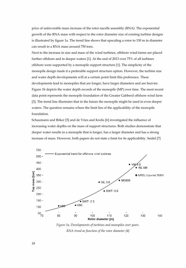
price of unfavorable mass increase of the rotor nacelle assembly (RNA). The exponential
growth of the RNA mass with respect to the rotor diameter size of existing turbine designs
is illustrated by figure 1a. The trend line shows that upscaling a rotor to 150 m in diameter
can result in a RNA mass around 750 tons.
Next to the increase in size and mass of the wind turbines, offshore wind farms are placed
further offshore and in deeper waters [1]. At the end of 2013 over 75% of all turbines
offshore were supported by a monopile support structure [1]. The simplicity of the
monopile design made it a preferable support structure option. However, the turbine size
and water depth developments will at a certain point limit this preference. These
developments lead to monopiles that are longer, have larger diameters and are heavier.
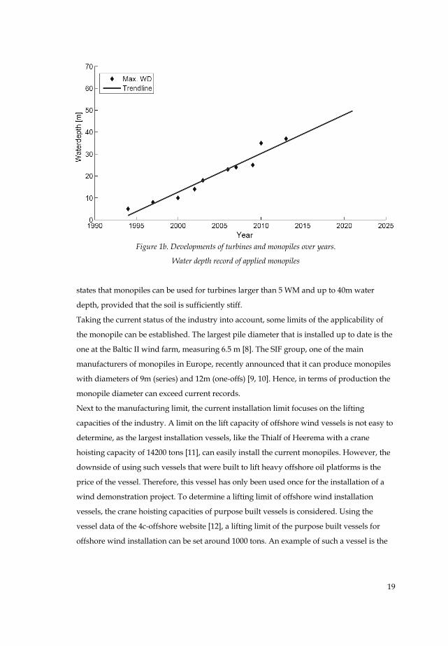
Figure 1b depicts the water depth records of the monopile (MP) over time. The most recent
data point represents the monopile foundation of the Greater Gabberd offshore wind farm
[3]. The trend line illustrates that in the future the monopile might be used in even deeper
waters. The question remains where the limit lies of the applicability of the monopile
foundation.
Schaumann and Böker [5] and de Vries and Krolis [6] investigated the influence of
increasing water depths on the mass of support structures. Both studies demonstrate that
deeper water results in a monopile that is longer, has a larger diameter and has a strong
increase of mass. However, both papers do not state a limit for its applicability. Seidel [7]
Figure 1a. Developments of turbines and monopiles over years.
RNA trend as function of the rotor diameter [4]
19
Figure 1b. Developments of turbines and monopiles over years.
Water depth record of applied monopiles
states that monopiles can be used for turbines larger than 5 WM and up to 40m water
depth, provided that the soil is sufficiently stiff.
Taking the current status of the industry into account, some limits of the applicability of
the monopile can be established. The largest pile diameter that is installed up to date is the
one at the Baltic II wind farm, measuring 6.5 m [8]. The SIF group, one of the main
manufacturers of monopiles in Europe, recently announced that it can produce monopiles
with diameters of 9m (series) and 12m (one-offs) [9, 10]. Hence, in terms of production the
monopile diameter can exceed current records.
Next to the manufacturing limit, the current installation limit focuses on the lifting
capacities of the industry. A limit on the lift capacity of offshore wind vessels is not easy to
determine, as the largest installation vessels, like the Thialf of Heerema with a crane
hoisting capacity of 14200 tons [11], can easily install the current monopiles. However, the
downside of using such vessels that were built to lift heavy offshore oil platforms is the
price of the vessel. Therefore, this vessel has only been used once for the installation of a
wind demonstration project. To determine a lifting limit of offshore wind installation
vessels, the crane hoisting capacities of purpose built vessels is considered. Using the
vessel data of the 4c-offshore website [12], a lifting limit of the purpose built vessels for
offshore wind installation can be set around 1000 tons. An example of such a vessel is the
20
new built Aeolus of marine contractor Van Oord with a crane hoisting capacity of 900 tons
[13, 14].
1.2 Objective
This paper demonstrates how the RNA mass of a reference turbine influences the design of
monopile support structures. The results are used to consider the applicability of the
monopile in future wind farms that are placed in deeper water and with heavier turbines.
Furthermore, this study provides turbine developers with insight on the potential to
reduce the required amount of support structure steel as a result of the RNA mass
reduction for a 5 MW turbine. Additionally, the results support the selection of the support
structure type in early design stages of future wind farms for similar turbines.
1.3 Approach
The NREL 5.0MW turbine, the corresponding turbine tower and the environmental
conditions of the Ijmuiden shallow water depth site of the UPWIND project are used in
this study [15]. The turbine mass is varied from 100-750 tons in steps of 50 tons. For each of
the RNA masses a finite element (FE) model of the monopile, transition piece (TP) and
turbine is made in Ansys. This FE model consists out of pipe elements for the monopile,
transition piece and turbine tower. De Vries and Krolis [6] concluded that buckling checks
for ULS conditions are fulfilled with a diameter D over wall thickness t ratio of 80 at
locations around the mudline of the monopile designs. In this paper a fixed D/t ratio of 75
is used for the design of the monopile and transition piece. This is done to account for the
effect of fatigue on the required wall thickness. The effect of this choice is also be
investigated in this paper. The RNA of the turbine is taken into account as a lumped mass
on top of the turbine tower. The overlap between the monopile and the transition piece is
taken into account as one cylinder with a wall thickness equal to the sum of the thicknesses
of both cylinders. The soil is taken into account as discrete soil springs equal to Zaaijer [16]
representation of discrete soil springs. These springs are determined with the method
presented in the API standard [17]. For the natural frequency calculation in this analysis
the stiffnesses of the non-linear soil springs are linearized around the unloaded
situation.
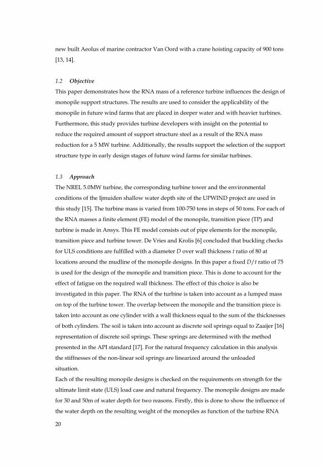
Each of the resulting monopile designs is checked on the requirements on strength for the
ultimate limit state (ULS) load case and natural frequency. The monopile designs are made
for 30 and 50m of water depth for two reasons. Firstly, this is done to show the influence of
the water depth on the resulting weight of the monopiles as function of the turbine RNA
21
mass. Secondly, a water depth of 30m is comparable to current activities and 50m water
depth is the maximum in the Dutch sector of the North Sea. Fatigue calculations and
optimization of the monopile design are not performed within this analysis. In figure 2 a
flow diagram of the used approach is given.
Figure 2. Approach of the analysis
22
2 Definition of the case study
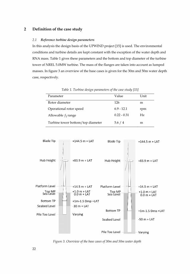
2.1 Reference turbine design parameters
In this analysis the design basis of the UPWIND project [15] is used. The environmental
conditions and turbine details are kept constant with the exception of the water depth and
RNA mass. Table 1 gives these parameters and the bottom and top diameter of the turbine
tower of NREL 5.0MW turbine. The mass of the flanges are taken into account as lumped
masses. In figure 3 an overview of the base cases is given for the 30m and 50m water depth
case, respectively.
Table 1. Turbine design parameters of the case study [15]
Parameter Value Unit
Rotor diameter 126 m
Operational rotor speed 6.9 - 12.1 rpm
Allowable 1f range 0.22 - 0.31 Hz
Turbine tower bottom/top diameter 5.6 / 4 m
Figure 3. Overview of the base cases of 30m and 50m water depth
23
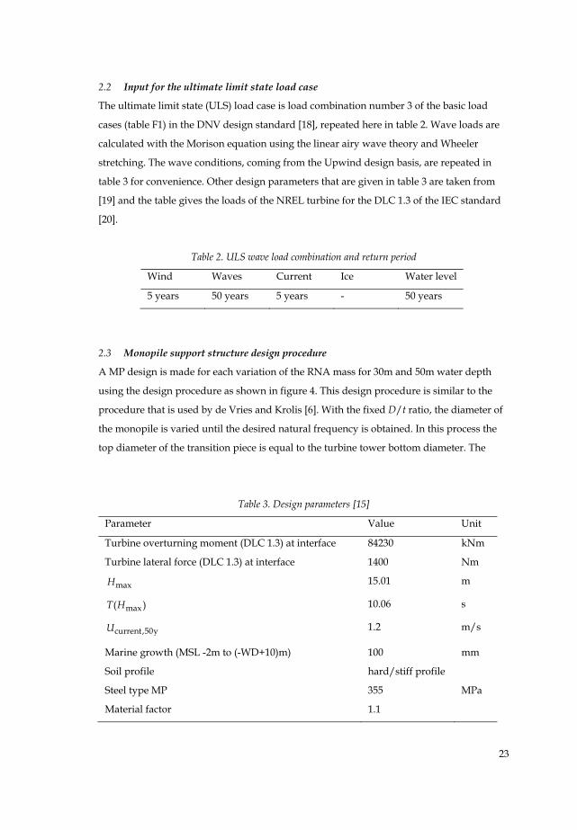
2.2 Input for the ultimate limit state load case
The ultimate limit state (ULS) load case is load combination number 3 of the basic load
cases (table F1) in the DNV design standard [18], repeated here in table 2. Wave loads are
calculated with the Morison equation using the linear airy wave theory and Wheeler
stretching. The wave conditions, coming from the Upwind design basis, are repeated in
table 3 for convenience. Other design parameters that are given in table 3 are taken from
[19] and the table gives the loads of the NREL turbine for the DLC 1.3 of the IEC standard
[20].
Table 2. ULS wave load combination and return period
Wind Waves Current Ice Water level
5 years 50 years 5 years - 50 years
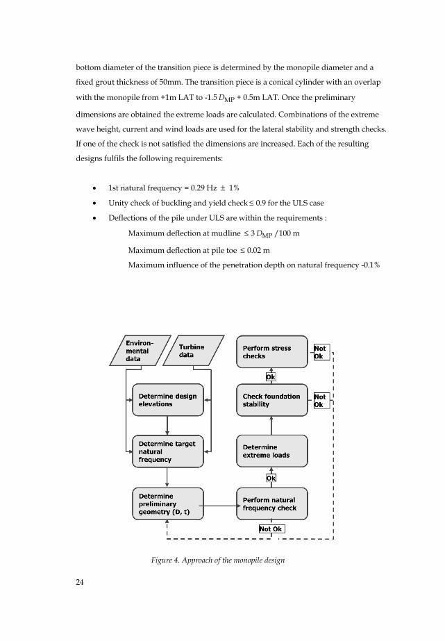
2.3 Monopile support structure design procedure
A MP design is made for each variation of the RNA mass for 30m and 50m water depth
using the design procedure as shown in figure 4. This design procedure is similar to the
procedure that is used by de Vries and Krolis [6]. With the fixed D/t ratio, the diameter of
the monopile is varied until the desired natural frequency is obtained. In this process the
top diameter of the transition piece is equal to the turbine tower bottom diameter. The
Table 3. Design parameters [15]
Parameter Value Unit
Turbine overturning moment (DLC 1.3) at interface 84230 kNm
Turbine lateral force (DLC 1.3) at interface 1400 Nm
maxH 15.01 m
max( )T H 10.06 s
current,50yU 1.2 m/s
Marine growth (MSL -2m to (-WD+10)m) 100 mm
Soil profile hard/stiff profile
Steel type MP 355 MPa
Material factor 1.1
24
bottom diameter of the transition piece is determined by the monopile diameter and a
fixed grout thickness of 50mm. The transition piece is a conical cylinder with an overlap
with the monopile from +1m LAT to -1.5 MPD + 0.5m LAT. Once the preliminary
dimensions are obtained the extreme loads are calculated. Combinations of the extreme
wave height, current and wind loads are used for the lateral stability and strength checks.
If one of the check is not satisfied the dimensions are increased. Each of the resulting
designs fulfils the following requirements:
• 1st natural frequency = 0.29 Hz ± 1%
• Unity check of buckling and yield check ≤ 0.9 for the ULS case
• Deflections of the pile under ULS are within the requirements :
Maximum deflection at mudline ≤ 3 MPD /100 m
Maximum deflection at pile toe ≤ 0.02 m
Maximum influence of the penetration depth on natural frequency -0.1%
Figure 4. Approach of the monopile design
25
3 Results
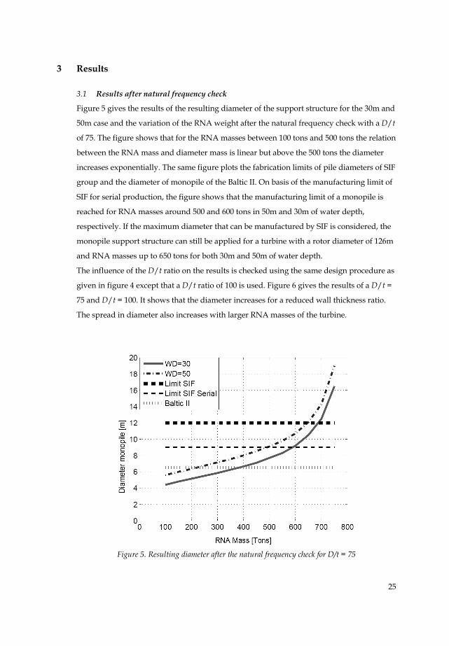
3.1 Results after natural frequency check
Figure 5 gives the results of the resulting diameter of the support structure for the 30m and
50m case and the variation of the RNA weight after the natural frequency check with a D/t
of 75. The figure shows that for the RNA masses between 100 tons and 500 tons the relation
between the RNA mass and diameter mass is linear but above the 500 tons the diameter
increases exponentially. The same figure plots the fabrication limits of pile diameters of SIF
group and the diameter of monopile of the Baltic II. On basis of the manufacturing limit of
SIF for serial production, the figure shows that the manufacturing limit of a monopile is
reached for RNA masses around 500 and 600 tons in 50m and 30m of water depth,
respectively. If the maximum diameter that can be manufactured by SIF is considered, the
monopile support structure can still be applied for a turbine with a rotor diameter of 126m
and RNA masses up to 650 tons for both 30m and 50m of water depth.
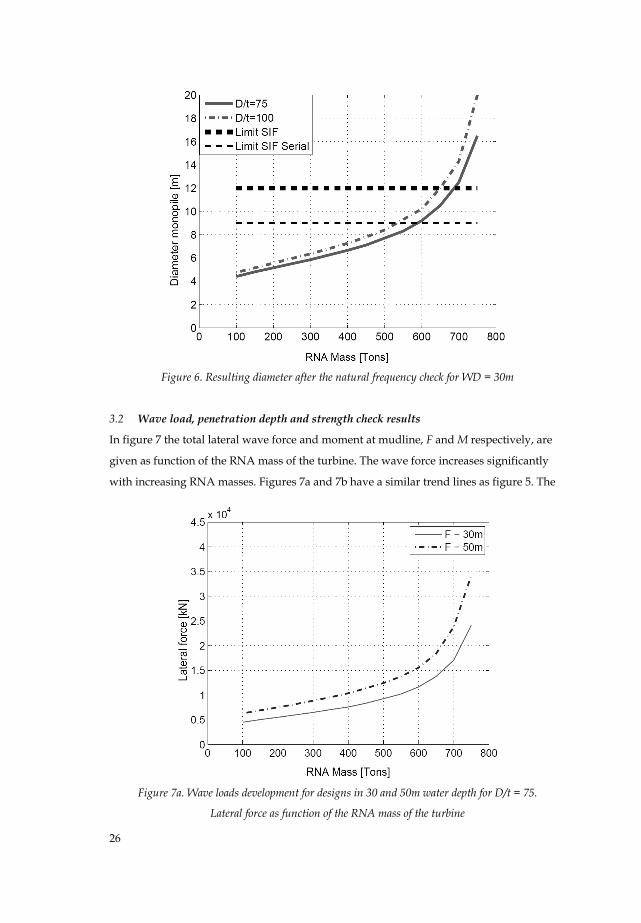
The influence of the D/t ratio on the results is checked using the same design procedure as
given in figure 4 except that a D/t ratio of 100 is used. Figure 6 gives the results of a D/t =
75 and D/t = 100. It shows that the diameter increases for a reduced wall thickness ratio.
The spread in diameter also increases with larger RNA masses of the turbine.
Figure 5. Resulting diameter after the natural frequency check for D/t = 75
26
Figure 6. Resulting diameter after the natural frequency check for WD = 30m
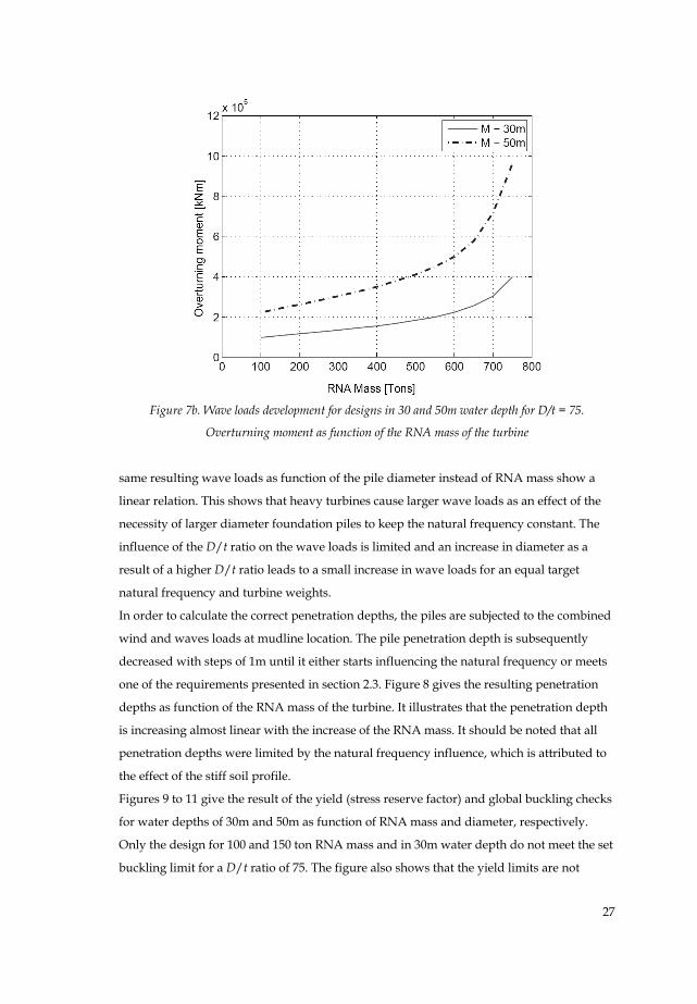
3.2 Wave load, penetration depth and strength check results
In figure 7 the total lateral wave force and moment at mudline, F and M respectively, are
given as function of the RNA mass of the turbine. The wave force increases significantly
with increasing RNA masses. Figures 7a and 7b have a similar trend lines as figure 5. The
Figure 7a. Wave loads development for designs in 30 and 50m water depth for D/t = 75.
Lateral force as function of the RNA mass of the turbine
27
Figure 7b. Wave loads development for designs in 30 and 50m water depth for D/t = 75.
Overturning moment as function of the RNA mass of the turbine
same resulting wave loads as function of the pile diameter instead of RNA mass show a
linear relation. This shows that heavy turbines cause larger wave loads as an effect of the
necessity of larger diameter foundation piles to keep the natural frequency constant. The
influence of the D/t ratio on the wave loads is limited and an increase in diameter as a
result of a higher D/t ratio leads to a small increase in wave loads for an equal target
natural frequency and turbine weights.
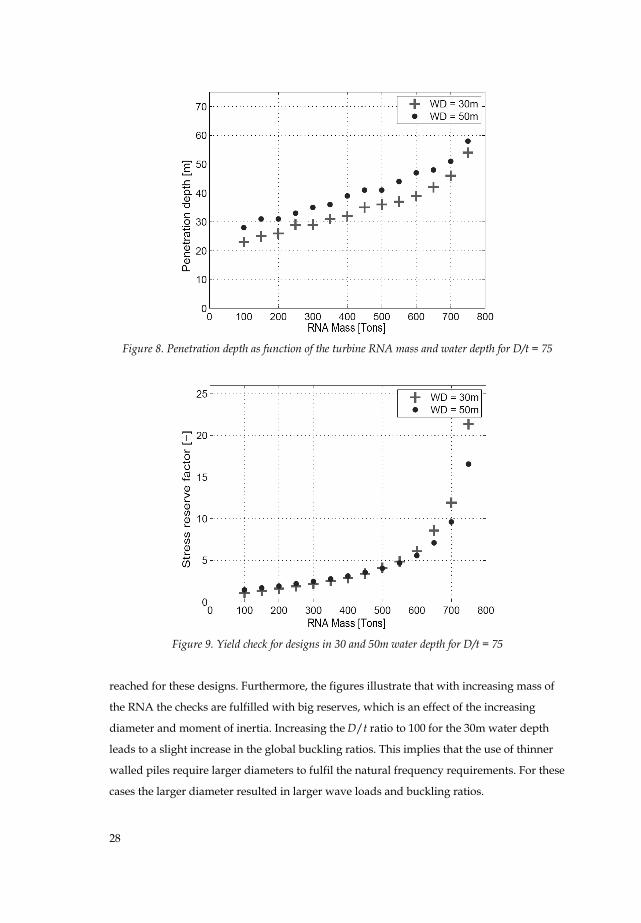
In order to calculate the correct penetration depths, the piles are subjected to the combined
wind and waves loads at mudline location. The pile penetration depth is subsequently
decreased with steps of 1m until it either starts influencing the natural frequency or meets
one of the requirements presented in section 2.3. Figure 8 gives the resulting penetration
depths as function of the RNA mass of the turbine. It illustrates that the penetration depth
is increasing almost linear with the increase of the RNA mass. It should be noted that all
penetration depths were limited by the natural frequency influence, which is attributed to
the effect of the stiff soil profile.
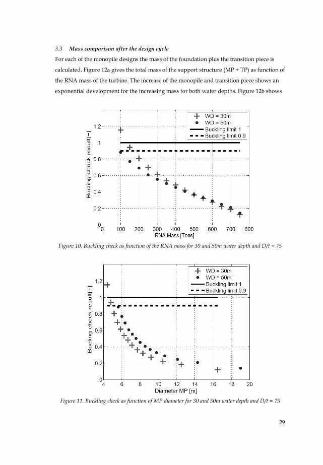
Figures 9 to 11 give the result of the yield (stress reserve factor) and global buckling checks
for water depths of 30m and 50m as function of RNA mass and diameter, respectively.
Only the design for 100 and 150 ton RNA mass and in 30m water depth do not meet the set
buckling limit for a D/t ratio of 75. The figure also shows that the yield limits are not
28
Figure 8. Penetration depth as function of the turbine RNA mass and water depth for D/t = 75
Figure 9. Yield check for designs in 30 and 50m water depth for D/t = 75
reached for these designs. Furthermore, the figures illustrate that with increasing mass of
the RNA the checks are fulfilled with big reserves, which is an effect of the increasing
diameter and moment of inertia. Increasing the D/t ratio to 100 for the 30m water depth
leads to a slight increase in the global buckling ratios. This implies that the use of thinner
walled piles require larger diameters to fulfil the natural frequency requirements. For these
cases the larger diameter resulted in larger wave loads and buckling ratios.
29
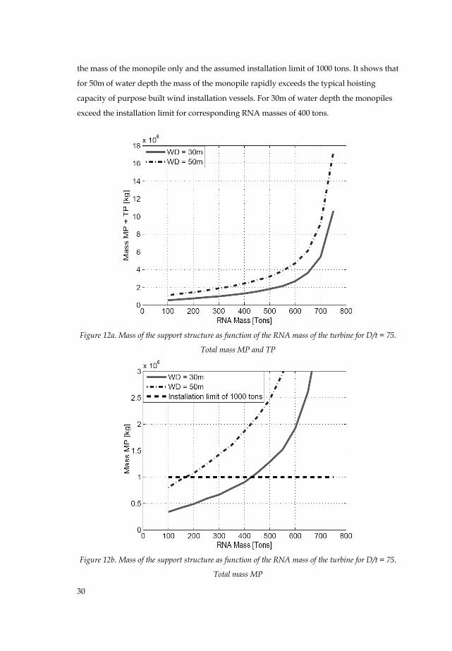
3.3 Mass comparison after the design cycle
For each of the monopile designs the mass of the foundation plus the transition piece is
calculated. Figure 12a gives the total mass of the support structure (MP + TP) as function of
the RNA mass of the turbine. The increase of the monopile and transition piece shows an
exponential development for the increasing mass for both water depths. Figure 12b shows
Figure 10. Buckling check as function of the RNA mass for 30 and 50m water depth and D/t = 75
Figure 11. Buckling check as function of MP diameter for 30 and 50m water depth and D/t = 75
30
the mass of the monopile only and the assumed installation limit of 1000 tons. It shows that
for 50m of water depth the mass of the monopile rapidly exceeds the typical hoisting
capacity of purpose built wind installation vessels. For 30m of water depth the monopiles
exceed the installation limit for corresponding RNA masses of 400 tons.
Figure 12a. Mass of the support structure as function of the RNA mass of the turbine for D/t = 75.
Total mass MP and TP
Figure 12b. Mass of the support structure as function of the RNA mass of the turbine for D/t = 75.
Total mass MP
31
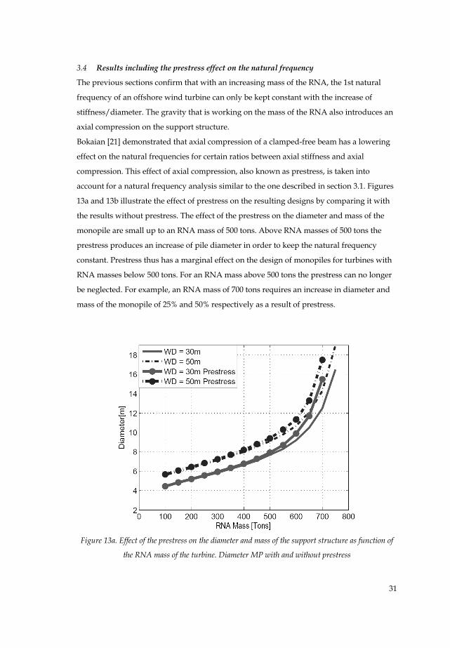
3.4 Results including the prestress effect on the natural frequency
The previous sections confirm that with an increasing mass of the RNA, the 1st natural
frequency of an offshore wind turbine can only be kept constant with the increase of
stiffness/diameter. The gravity that is working on the mass of the RNA also introduces an
axial compression on the support structure.
Bokaian [21] demonstrated that axial compression of a clamped-free beam has a lowering
effect on the natural frequencies for certain ratios between axial stiffness and axial
compression. This effect of axial compression, also known as prestress, is taken into
account for a natural frequency analysis similar to the one described in section 3.1. Figures
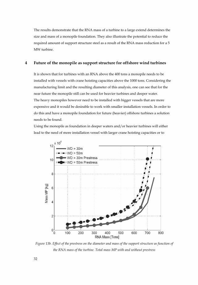
13a and 13b illustrate the effect of prestress on the resulting designs by comparing it with
the results without prestress. The effect of the prestress on the diameter and mass of the
monopile are small up to an RNA mass of 500 tons. Above RNA masses of 500 tons the
prestress produces an increase of pile diameter in order to keep the natural frequency
constant. Prestress thus has a marginal effect on the design of monopiles for turbines with
RNA masses below 500 tons. For an RNA mass above 500 tons the prestress can no longer
be neglected. For example, an RNA mass of 700 tons requires an increase in diameter and
mass of the monopile of 25% and 50% respectively as a result of prestress.
Figure 13a. Effect of the prestress on the diameter and mass of the support structure as function of
the RNA mass of the turbine. Diameter MP with and without prestress
32
The results demonstrate that the RNA mass of a turbine to a large extend determines the
size and mass of a monopile foundation. They also illustrate the potential to reduce the
required amount of support structure steel as a result of the RNA mass reduction for a 5
MW turbine.
4 Future of the monopile as support structure for offshore wind turbines
It is shown that for turbines with an RNA above the 400 tons a monopile needs to be
installed with vessels with crane hoisting capacities above the 1000 tons. Considering the
manufacturing limit and the resulting diameter of this analysis, one can see that for the
near future the monopile still can be used for heavier turbines and deeper water.
The heavy monopiles however need to be installed with bigger vessels that are more
expensive and it would be desirable to work with smaller installation vessels. In order to
do this and have a monopile foundation for future (heavier) offshore turbines a solution
needs to be found.
Using the monopile as foundation in deeper waters and/or heavier turbines will either
lead to the need of more installation vessel with larger crane hoisting capacities or to
Figure 13b. Effect of the prestress on the diameter and mass of the support structure as function of
the RNA mass of the turbine. Total mass MP with and without prestress
33
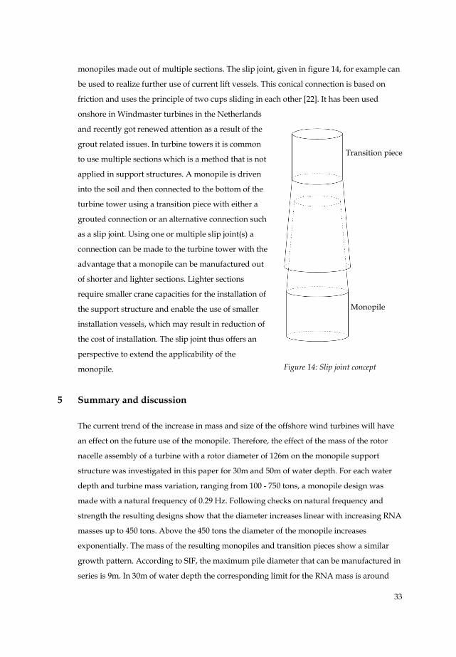
monopiles made out of multiple sections. The slip joint, given in figure 14, for example can
be used to realize further use of current lift vessels. This conical connection is based on
friction and uses the principle of two cups sliding in each other [22]. It has been used
onshore in Windmaster turbines in the Netherlands
and recently got renewed attention as a result of the
grout related issues. In turbine towers it is common
to use multiple sections which is a method that is not
applied in support structures. A monopile is driven
into the soil and then connected to the bottom of the
turbine tower using a transition piece with either a
grouted connection or an alternative connection such
as a slip joint. Using one or multiple slip joint(s) a
connection can be made to the turbine tower with the
advantage that a monopile can be manufactured out
of shorter and lighter sections. Lighter sections
require smaller crane capacities for the installation of
the support structure and enable the use of smaller
installation vessels, which may result in reduction of
the cost of installation. The slip joint thus offers an
perspective to extend the applicability of the
monopile.
5 Summary and discussion
The current trend of the increase in mass and size of the offshore wind turbines will have
an effect on the future use of the monopile. Therefore, the effect of the mass of the rotor
nacelle assembly of a turbine with a rotor diameter of 126m on the monopile support
structure was investigated in this paper for 30m and 50m of water depth. For each water
depth and turbine mass variation, ranging from 100 - 750 tons, a monopile design was
made with a natural frequency of 0.29 Hz. Following checks on natural frequency and
strength the resulting designs show that the diameter increases linear with increasing RNA
masses up to 450 tons. Above the 450 tons the diameter of the monopile increases
exponentially. The mass of the resulting monopiles and transition pieces show a similar
growth pattern. According to SIF, the maximum pile diameter that can be manufactured in
series is 9m. In 30m of water depth the corresponding limit for the RNA mass is around
Figure 14: Slip joint concept
Monopile
Transition piece
34
600 tons. In 50m of water depth the corresponding limit for the RNA mass is around 500
tons. SIF’s manufacturing limit of one off’s piles at its site is 12m. With this diameter of
12m the monopile support structure can still be applied for turbines with RNA masses up
to 650 tons for both 30m and 50m of water depth. Furthermore, it is shown that the masses
of monopiles designed for turbines with an RNA mass above 400 tons are too large for
installation vessels with a crane capacity of 1000 tons or less. The applicability limit of the
monopile will thus be determined by either the manufacturing limit or the crane capacity
of the installation vessel. The inclusion of prestress effects of the RNA mass on the design
of the monopile is significant for RNA masses larger than 500 tons. For example, the
increase in diameter and mass of the monopile as a result of the prestress for an RNA mass
of 700 tons is 25% for 30m water depth and 50% for 50m water depth.
The results demonstrate that the RNA mass of a turbine to a large extend determines the
size and mass of the monopile foundation. They also illustrate the potential to reduce the
required amount of support structure steel as a result of the RNA mass reduction. It is
shown that to continue to use the monopile as foundation in deeper waters and/or (very)
heavy turbines, there is a need for more installation vessels with larger crane hoisting
capacities or monopiles that are made out of multiple sections. Considering the current top
masses and applied diameters the near future of the monopile still looks promising. The
use of a slip joint will make this future look even brighter.
The resulting monopile designs presented in this paper are meant to be used for
indications and insight. Fatigue calculations and optimization of the monopile designs
were not performed within this analysis. Fatigue calculations tend to result in a larger
required wall thickness compared to the required thickness after ULS calculations. To take
the effect of fatigue on the resulting wall thickness in account a D/t ratio of 75 was used in
comparison to the suggested 80 of de Vries and Krolis [6]. Optimization of the designs
could result in a smaller wall thicknesses and a reduction of monopile mass. It should be
noted that optimization should be done considering all requirements. If overall the wall
thickness is decreased/optimized on basis of the strength checks, it will result in a
diameter increase as result of the natural frequency requirement. This increase in diameter
can cancel (a part of) the envisioned weight decrease of the pile and result in larger wave
loads and buckling ratios.
It should be noted that the used soil profile, turbine and turbine tower design influence the
results presented in this paper. The used soil profile represents stiff soil conditions in the
Dutch North Sea. For softer soil the resulting diameter and mass would increase as larger
diameters are needed to compensate for the softener stiffness of the soil.
35
The rotor diameter of the turbine determines the total height of the offshore turbine and
was kept constant in this analysis. Turbines with larger rotors than 126m will result an
increase in length of the total structure. This increase in length will result in monopile
designs with larger diameters for similar RNA masses and natural frequency
requirements. Turbines with smaller rotors will have the opposite effect on the designs.
The turbine loads increase with a larger rotor which on its turn may result in a larger
required wall thickness to pass FLS and ULS checks. The choice of keeping the rotor
diameter constant may therefore underestimate the size and weight of resulting designs.
However, in the same analysis the turbine tower is kept constant. This is done as in most
cases the turbine tower is a part of the turbine and not to be altered by the marine
contractor. If the turbine tower would be optimized for each RNA mass and monopile
designs, the results will be less conservative. The presented masses of the monopiles are
therefore to be used for the purpose of insight.
Acknowledgements
The financial support of the FLOW research program is gratefully acknowledged.
www.flow-offshore.nl
References
[1] Corbetta G, “The European offshore wind industry - key trends and statistics” 2013.
The European Wind Energy Association, 2014
[2] Sieros G, Chaviaropoulos P, Sørensen JD, Bulder BH, Jamieson P. 2012. Upscaling wind
turbines: Theoretical and practical aspects and their impact on cost of energy. Wind
Energy Journal 2012; 15: 3-17. DOI: 10.1002/we.527
[3] 4c offshore website. Greater Gabbard wind farm webpage. www.4coffshore.com/
windfarms/greater-gabbardunited-kingdom-uk05.html, accessed July 2014
[4] Diepeveen NFB, On Fluid Power Transmission. Dissertation. Delft University of
Technology 2013
[5] Shaumann P, Böker C, “Can Jackets and tripods compete with monopiles?”,
Conference proceedings EWEA Offshore Wind. Copenhagen 2005
[6] de Vries WE, Krolis V, “Effects of deep water on monopile support structures for
offshore wind turbines”, Conference proceedings EWEC, Milan 2007
[7] Seidel M, “Feasibility of monopiles for large offshore wind turbines”. Conference
Proceedings DEWEK. Bremen 2010
36
[8] Offshorewind.biz website. News announcement. www.offshorewind.biz/2013/
09/27/germany-eewmanufactures-their-largest-monopile/, accessed December 2013
[9] SIF group website, News announcement, www.sif-group.com/en/spirit/
competences/state-of-the-art, accessed December 2013
[10] Offshorewind.biz website, News announcement. www.offshorewind.biz/2014/06/
30/sif-group-expands-itsproduction-capacity-manufactures-supersize-monopiles/.
accessed July 2014
[11] Heerema Thialf webpage. http://hmc.heerema.com/content/fleet/thialf/, accessed
July 2014
[12] 4c offshore website, “Details on construction vessels”, http://www.4coffshore.com/
windfarms/vessels.aspx?catId=3. accessed March 2014
[13] Van Oord Aeolus equipment leaflet, http://cdn.vanoord.com/sites/default/
files/leafletD_aeolus.pdf. Accessed march 2014
[14] Van Oord Web Announcement, www.vanoord.com/news/2014-offshore-installation-
vessel-aeolusoperational. accessed July 2014
[15] Fisher T, de Vries W, Schmidt B, “Upwind Design Basis” (WP4: Offshore Foundations
and support structures). Endowed chair of wind energy at the institute of aircraft
design Universität Stuttgart 2010
[16] Zaaijer MB, “Foundation models for the dynamic response of offshore wind turbines”,
Marine Renewable Energy Conference (MAREC) 2002. Newcastle.
[17] American Petroleum Institute. RP 2A-LRFD. “API Recommended Practices for
Planning, Designing and Constructing Fixed Offshore Platforms, Load and Resistance
Factor Design”, American Petroleum Institute 1993
[18] Det Norske Veritas (DNV). DNV-OS-J101. Offshore Standard: “Design of offshore
wind turbine structures”, Det Norske Veritas AS 2013
[19] Vemula NK, de Vries W, Fischer T, Cordle A, Schmidt B, “Design solution for the
Upwind reference offshore support structure” -Deliverable D4.2.5- (WP4: Offshore
Foundations and Support Structures), Upwind deliverable report, Upwind 2010
[20] International Electro technical Commission (IEC). IEC 61400-3: “Design requirements
for offshore wind turbines”, IEC 2009
[21] Bokaian A, “Natural frequencies of beams under compressive axial loads”, Journal of
Sound and Vibration 1988. 126 (l) 49-65.
[22] Segeren MLA, Lourens E., “Investigation of a slip joint connection between the
monopile and tower of an offshore wind turbine”, IET Renewable Power Generation
Journal 2014.