Embed Size (px)
Citation preview
Romanian Reports in Physics, Vol. 56, No. 3, P. 320-327, 2004
INFLUENCE OF SOME CARBON
NANOSTRUCTURES ON THE MESOPHASE PITCH DEVELOPMENT - A STRUCTURAL STUDY
I. PASUK1, C. BANCIU1, A.M. BONDAR1, G.A. RIMBU1, I. ION1,
I. STAMATIN2, I. MORJAN3, I. VOICU3, I. SANDU3
1 Advanced Research Institute for Electrical Engineering, 313 Splaiul Unirii, 74204
Bucharest, Romania, e-mail: [email protected] 2 University of Bucharest, Faculty of Physics, Bucharest-Magurele, M.G.11, Romania
3 National Institute for Lasers, Plasma and Radiation Physics, Laser Department, P.O. Box MG-36, R-76900 Bucharest, Romania
Abstract. Our study concerns with the investigation of the influence of additivation of purified
pitch with 0.05-1.5 % nanocarbon, upon the phase transformations during heat treatment up to 440oC. Differences were found between the composites with different nanocarbon types, as function of the additive amount. These differences seem to be related to the fraction of single graphene layer in the material, ring defects in the graphene sheets, MP germination rate.
Key words: turbostratic structure, X-ray diffraction, optical microscopy, graphene sheet,
mesophase, nanocarbon, composite,
1. INTRODUCTION Most solid carbons (carbon blacks, pitches, cokes, graphite etc.) are
constituted of carbon atoms in sp2 hybridization state. Such materials have as basic structural unit the graphene sheet, which is a planar hexagonal lattice formed by C atoms. The polyaromatic graphene sheets tend to form locally ordered associations with more or less parallel and equidistant sheets (stacks). In graphite these stacks are built up of hundreds of parallel sheets, with micrometric diameter, that form a tri-dimensional crystal structure that is described by a well defined hexagonal or rhombohedra unit cell. In many other carbons the aromatic, nano-scale diameter, sheets inside the stacks are distributed almost parallel and equidistant, but with no other structural correlation between the sheets - turbostratic graphite structure [1]. The turbostratic graphite structure can be considered as one bidimensional. This kind of structure can be easily identified on the basis of the absence of any reflexions from a tree dimensional unit cell (other than (002), (004) etc.) in the X-ray diffraction patterns [1].
Pitches are carbonaceous materials originating from different treatments of different precursors. During heat treatment, the material softens and at the temperature for which the viscosity shows a strong minimum (usually between
Influence of some carbon nanostructures
321
420-450oC), anisotropic spherical bodies - called mesophase (MP) - appear suddenly by demixtion from the isotropic matrix, as a liquid drop inside a liquid. These spherical mesophase bodies were described by Brooks and Taylor [2]. Due to their optical anisotropy and micrometric sizes they can be well observed by polarized light optical microscopy on polished sections. At higher temperatures these spheres coalesce and form a material, which is still plastic, called bulk MP. By further heat treatment, MP gives rise to carbons that are highly graphitizable. So, the term MP is well known in the domain and refers to a phase that lies between the liquid isotropic phase, without molecular order and with high molecular mobility, and the rigidly ordered solid phase, for which the mobili ty of the individual molecules is restricted.
The isotropic pitch matrix is constituted mainly of polyaromatic entities saturated by aromatic CH groups and with many aliphatic hydrocarbon side-chains. This disordered phase become more and more ordered as the low weight radicals volatilizes during heating.
The texture of graphite is highly controlled by the material structure when it is transformed to the liquid crystalli ne state. The nucleation, growth and texturing of the MP are strongly dependent upon the added particles, rheological characteristics of the precursors and temperature. It is well known that foreign microparticles and high molecular compounds, inherent in the CTP, generally inhibit the development and coalescence of mesophase spheres, and so, they are usually removed in view of a better graphitization. Many studies have been published concerning the influence of controlled adding of different additives and their influence on the phase transformations [e.g.3-5].
The morphology of NC particles revealed by HRTEM is almost spherical with a disordered appearance; the small spherical particles could form chains. But an underlying graphitic turbostratic structure, with slightly parallel and equidistant graphene layers, was put in evidence by X-ray and electron diffraction. If a high curvature of the graphene molecule is introduced fullerene formation could be induced. The fullerene formation is based on the introduction of pentagonal, heptagonal or other kind of “defect” rings between the hexagonal rings of the graphene sheets, which favorize a higher curvature of the sheet [6].
Earlier studies [7] have drawn our attention on the possible enhancement of MP development by a certain, very little, percent of NC added (around 0.1 wt. %), when an increasing amount (up to 5 %) of the same add lead to an inhibition effect. Our present study concerns with the investigation of some pitch-NC composites with very littl e NC contents (from 0.05 to 1.5 wt.%).
2. EXPERIMENTAL
Samples preparation
Nanocarbons were obtained by laser pyrolysis of different hydrocarbon based
mixtures. The synthesis of carbon nanostructures by laser pyrolysis of
Pasuk et al.
322
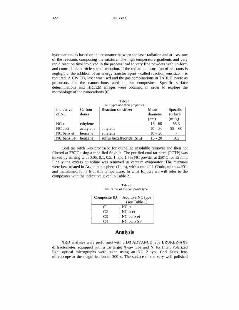
hydrocarbons is based on the resonance between the laser radiation and at least one of the reactants composing the mixture. The high temperature gradients and very rapid reaction time involved in the process lead to very fine powders with uniform and controllable particle size distribution. If the radiation absorption of reactants is negligible, the addition of an energy transfer agent - called reaction sensitizer - is required. A CW CO2 laser was used and the gas combinations in TABLE 1were as precursors for the nanocarbons used in our composites. Specific surface determinations and HRTEM images were obtained in order to explore the morphology of the nanocarbons [6].
Table 1
NC types and their properties
Indicative of NC
Carbon donor
Reaction sensitizer Mean diameter (nm)
Specific surface (m2/g)
NC et ethylene - 15 - 60 55.3 NC acet acetylene ethylene 10 – 30 55 – 60 NC benz et benzene ethylene 10 – 20 - NC benz SF benzene sulfur hexafluoride (SF6) 10 - 20 165
Coal tar pitch was processed for quinoline insoluble removal and then hot
fil tered at 270oC using a modified Soxhlet. The purified coal tar pitch (PCTP) was mixed by stirring with 0.05, 0.1, 0.5, 1, and 1.5% NC powder at 250oC for 15 min. Finally the excess quinoline was removed in vacuum evaporator. The mixtures were heat treated in Argon atmosphere (1atm), with a rate of 1oC/min, up to 440oC, and maintained for 3 h at this temperature. In what follows we will refer to the composites with the indicative given in Table 2.
Table 2
Indicative of the composite type
Composite ID Additive NC type (see Table 1)
C1 NC et C2 NC acet C3 NC benz et C4 NC benz SF
Analysis
XRD analyses were performed with a D8 ADVAN CE type BRUKER-AXS
diffractometer, equipped with a Cu target X-ray tube and Ni Kβ fil ter. Polarized light optical micrographs were taken using an NU 2 type Carl Zeiss Jena microscope at the magnification of 300 x. The surface of the very well polished
Influence of some carbon nanostructures
323
samples was observed in reflected light, between crossed polarizer, with a λ/4 retarded plate inserted between the objective and the analyzer.
The XRD patterns were processed mainly for to deduce the following crystallographic parameters: the interlayer spacing, d (002), the stacking height, Lc, and the layer diameter, La. d(002) was deduced from the (002) band position; Lc and La were esteemed from the (002) and (10) line broadening, respectively, using Scherrer formula with k=1, and k=1.84, for three and two-dimensional ordering, respectively [e.g.8]. Another important parameter is the fraction of single layer relative to the total graphene sheets both stacked and single. We estimated this parameter following Liu et al [9]. The authors have deduced on the basis of some theoretical assessments that B/A (defined as it is shown in Fig. 2) is almost inversely proportional to the single layer fraction.
3. RESULTS AND DISCUSSION The examination of the optical micrographs clearly reveals that, at 0.05%
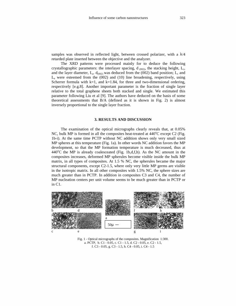
NC, bulk MP is formed in all the composites heat-treated at 440oC except C2 (Fig. 1b-i). At the same time PCTP without NC addition shows only very small sized MP spheres at this temperature (Fig. 1a). In other words NC addition favors the MP development, so that the MP formation temperature is much decreased, thus at 440oC the MP is already coalesceated (Fig. 1b,d,f,h). As the NC amount in the composites increases, deformed MP spherules become visible inside the bulk MP matrix, in all types of composites. At 1.5 % NC, the spherules became the major structural components, except C2-1.5, where only very little MP germs are visible in the isotropic matrix. In all other composites with 1.5% NC, the sphere sizes are much greater than in PCTP. In addition in composites C3 and C4, the number of MP nucleation centers per unit volume seems to be much greater than in PCTP or in C1.
Fig. 1 - Optical micrographs of the composites. Magnification 1:300. a. PCTP, b. C1 - 0.05, c. C1 - 1.5, d. C2 - 0.05, e. C2 - 1.5,
f. C3 - 0.05, g. C3 - 1.5, h. C4 - 0.05, i. C4 - 1.5
b d
c e
a
f h
g i
50µ
Pasuk et al.
324
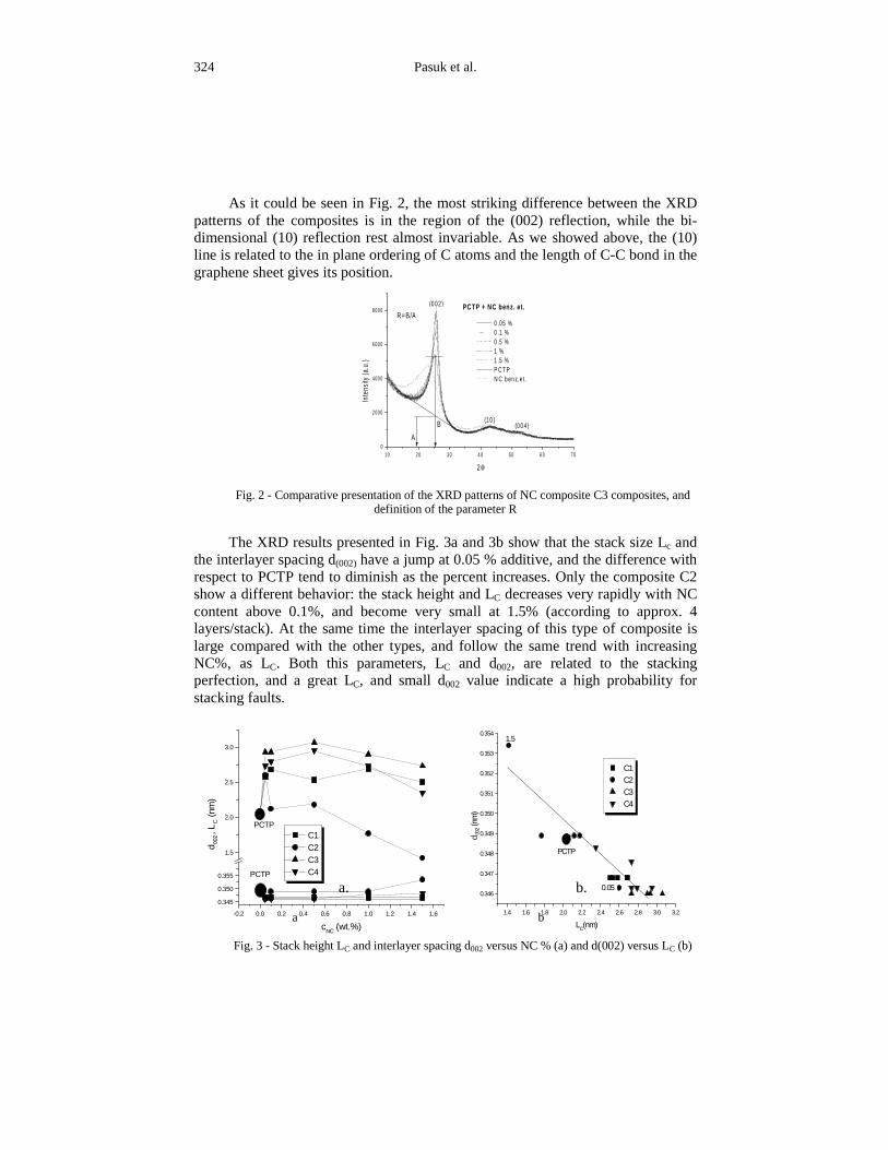
As it could be seen in Fig. 2, the most striking difference between the XRD patterns of the composites is in the region of the (002) reflection, while the bi-dimensional (10) reflection rest almost invariable. As we showed above, the (10) line is related to the in plane ordering of C atoms and the length of C-C bond in the graphene sheet gives its position.
Fig. 2 - Comparative presentation of the XRD patterns of NC composite C3 composites, and
definition of the parameter R The XRD results presented in Fig. 3a and 3b show that the stack size Lc and
the interlayer spacing d(002) have a jump at 0.05 % additive, and the difference with respect to PCTP tend to diminish as the percent increases. Only the composite C2 show a different behavior: the stack height and LC decreases very rapidly with NC content above 0.1%, and become very small at 1.5% (according to approx. 4 layers/stack). At the same time the interlayer spacing of this type of composite is large compared with the other types, and follow the same trend with increasing NC%, as LC. Both this parameters, LC and d002, are related to the stacking perfection, and a great LC, and small d002 value indicate a high probabili ty for stacking faults.
a. b.
a b
Fig. 3 - Stack height LC and interlayer spacing d002 versus NC % (a) and d(002) versus LC (b)
1.4 1.6 1.8 2.0 2.2 2.4 2.6 2.8 3.0 3.2
0.346
0.347
0.348
0.349
0.350
0.351
0.352
0.353
0.354
0.05
1.5
PCTP
C1 C2 C3 C4
d00
2(n
m)
LC(nm)
-0.2 0.0 0.2 0.4 0.6 0.8 1.0 1.2 1.4 1.6
0.345
0.350
0.355
1.5
2.0
2.5
3.0
PCTP
PCTP C1 C2 C3 C4
d 002
, LC (n
m)
cNC
(wt.%)
1 0 2 0 3 0 4 0 5 0 6 0 7 00
2 00 0
4 00 0
6 00 0
8 00 0R=B/A
(0 0 4)(1 0 )
(0 0 2)
B
A
PCTP + NC benz. et.
0 .05 % 0 .1 % 0 .5 % 1 % 1 .5 % P C T P N C b en z.e t.
Inte
nsity
(a.u
.)
2θ
Influence of some carbon nanostructures
325
From the correlation of these results with the microphotos in Fig. 1 some
conclusions could be drawn: - Taking into account that C2-1.5 is almost isotropic, we can deduce that
the mean height of the stacks inside the isotropic pitch matrix is a little smaller than 1.6 nm, with an interlayer spacing a lit tle greater than 0.353 nm, that is, it contains stacks with 4, or less, graphene layers. At the coalescence, when the isotropic matrix is completely transformed into MP, the mean LC lies between 2.6 –2.8 nm and the mean value of d002 lies between 0.3460-0.3475 nm, for all composites. It results that coalesceated MP is constituted from stacks of 7–8 layers. Thus all composites belong to this range of stacked layer number.
- Following the graph in Fig.3b we can deduce that the modification of the average values of LC and d002 is mainly due to the transformation of isotropic pitch in MP. Both parameters show a wide range variation for C2 composites, while for the other composites, where the MP is almost coalesceated at all concentrations, these parameters vary only a few. This figure could be interpreted as, from the point of view of the stacking, all composites seem to obey roughly the same rule, and the PCTP sample that serves as “blank” integrates well in the same frame.
According to the turbostratic model of the paracrystalli ne graphite the integrated intensity of the bi-dimensional (10) line is related to the total number of graphene sheets. The (002) reflection is a consequence of the stacking of these layers in a turbostratic structure. As the stack height (LC) increases, the line become thinner and higher preserving the same area if the average number of the stacks don’ t change. So, the area under the (002) peak is proportional to the total amount of stacks in the sample. Multiplying this with the average number of layers in a stack, M, we obtain the total number of layers organized in stacks. Thus the ratio:
10
002
A
MA ⋅ will give the fraction of stacked layers relative to the total number of
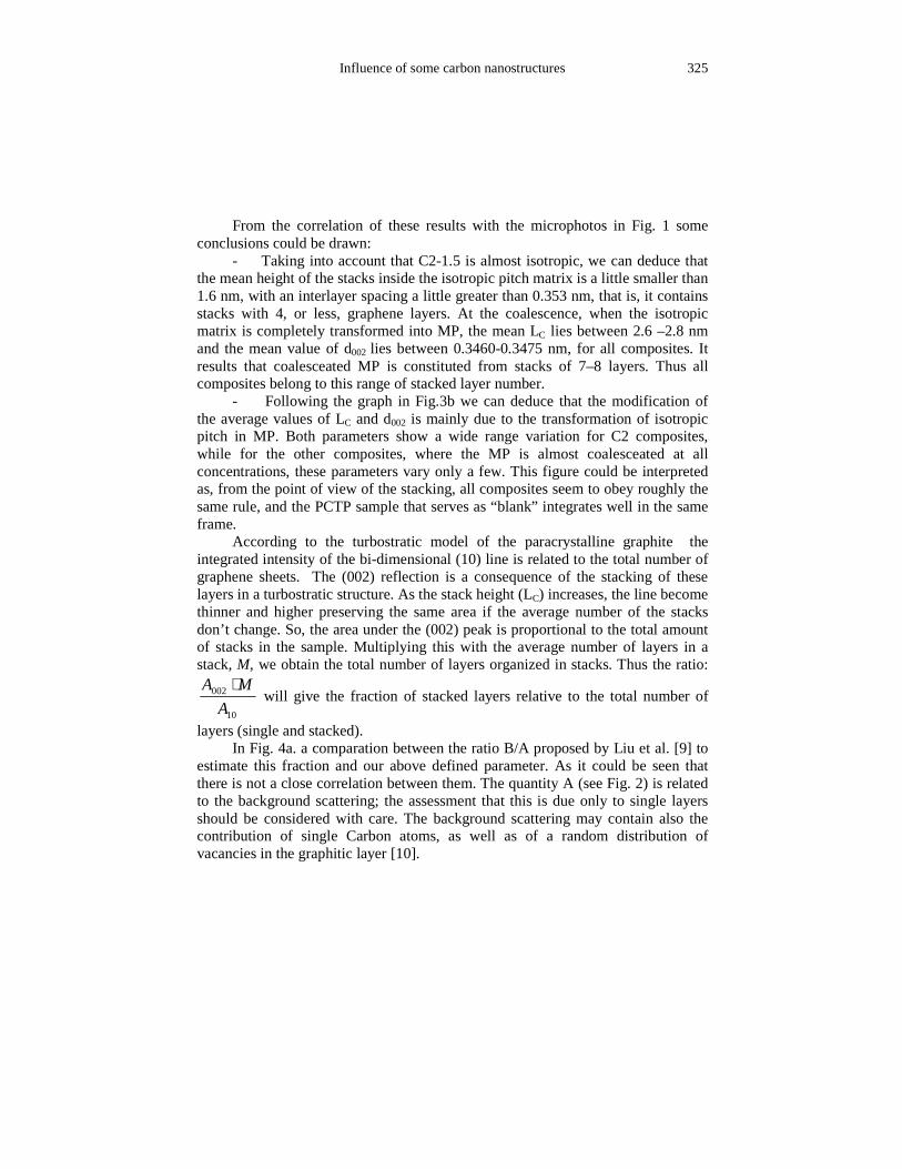
layers (single and stacked). In Fig. 4a. a comparation between the ratio B/A proposed by Liu et al. [9] to
estimate this fraction and our above defined parameter. As it could be seen that there is not a close correlation between them. The quantity A (see Fig. 2) is related to the background scattering; the assessment that this is due only to single layers should be considered with care. The background scattering may contain also the contribution of single Carbon atoms, as well as of a random distribution of vacancies in the graphitic layer [10].
Pasuk et al.
326
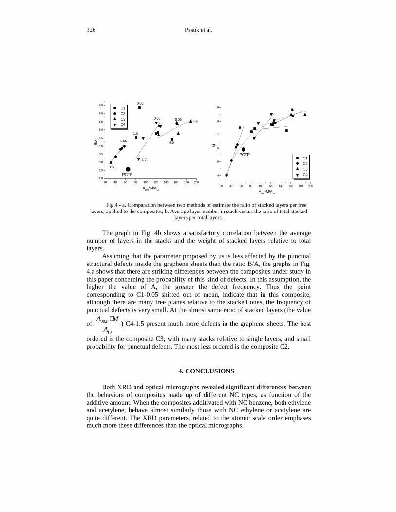
Fig.4 - a. Comparation between two methods of estimate the ratio of stacked layers per free layers, applied to the composites; b. Average layer number in stack versus the ratio of total stacked
layers per total layers.
The graph in Fig. 4b shows a satisfactory correlation between the average
number of layers in the stacks and the weight of stacked layers relative to total layers.
Assuming that the parameter proposed by us is less affected by the punctual structural defects inside the graphene sheets than the ratio B/A, the graphs in Fig. 4.a shows that there are striking differences between the composites under study in this paper concerning the probability of this kind of defects. In this assumption, the higher the value of A, the greater the defect frequency. Thus the point corresponding to C1-0.05 shifted out of mean, indicate that in this composite, although there are many free planes relative to the stacked ones, the frequency of punctual defects is very small. At the almost same ratio of stacked layers (the value
of 10
002
A
MA ⋅) C4-1.5 present much more defects in the graphene sheets. The best
ordered is the composite C3, with many stacks relative to single layers, and small probabil ity for punctual defects. The most less ordered is the composite C2.
4. CONCLUSIONS
Both XRD and optical micrographs revealed significant differences between the behaviors of composites made up of different NC types, as function of the additive amount. When the composites additivated with NC benzene, both ethylene and acetylene, behave almost similarly those with NC ethylene or acetylene are quite different. The XRD parameters, related to the atomic scale order emphases much more these differences than the optical micrographs.
20 40 60 80 100 120 140 160 180 200
4
5
6
7
8
9
PCTP C1 C2 C3 C4
M
A002
*M/A10
20 40 60 80 100 120 140 160 180 2002.0
2.5
3.0
3.5
4.0
4.5
5.0
5.5
6.0
6.5
0.05
1.5
0.5
0.5
1.5
0.05
0.05
1.5
0.05
PCTP
C1 C2 C3 C4
B/A
A002
*M/A10
Influence of some carbon nanostructures
327
Further investigations must be undertaken in order to explain the differences between pitch-NC composites (the electron affinity of different types of NC particles, the influence of surface structure of NC particles etc). If better understanding will be achieved, the NC additivation of pitch could became an efficient method of control and design of MP and graphitic structures and this could lead to interesting practical applications.
REFERENCES
1. J.Biscoe, B.E. warren, J.Appl. Phys. 13, 364, 1942. 2. J.D.Brooks, G.H.Taylor, The formation of some graphitizing carbon, P.L.Walker, Jr editor, Chemistry and Physics of Carbon, 4, Edward Arnold LTD, London, 243-286, 1968. 3. M. Bernhauer, M.Braun, K.J.Huttinger, Carbon 32, 941, 1994. 4. L.E.Jones, P.A.Thrower, Carbon 29, 251, 1991. 5. T.Eichner et.al., Carbon 34, 1367, 1996. 6. I. Morjan, et. al. – Gas composition in laser pyrolysis of hydrocarbon–based mixtures: influence on soot morphology, Carbon’03, Oviedo, Spain, 2003. 7. G.A.Rimbu, C.Banciu, I.Ion, I.Pasuk, A.M.Bondar, I.Stamatin, I.Morjan, I.Sandu - Structural modifications induced by micro and nano-carbons on fractionated coal tar pitch, Carbon’02, Beijing, China, 2002. 8. P.B. Hirsch - Proc.Roy.Soc. 226 A, 143 1954. 9. Y.Liu, J.S.Xue, T.Zheng, J.R.Dahn – Mechanism of lithium insertion in hard carbons prepared by pyrolysis of epoxy resins, Carbon 34, 193, 1996. 10. W.Ruland, X-ray diff raction studies on carbon and graphite, P.L.Walker, Jr editor, Chemistry and Physics of Carbon, 4, Edward Arnold LTD, London, 1-84, 1968.