Embed Size (px)
Citation preview
Influence of grinding operations
on surface integrity and chloride
induced stress corrosion
cracking of stainless steels
NIAN ZHOU
Licentiate Thesis in Chemistry
KTH Royal Institute of Technology
School of Chemical Science and Engineering
Department of Chemistry
SE -100 44 Stockholm, Sweden

TRITA-CHE Report 2016:5
ISSN 1654-1081 ISBN 978-91-7595-838-5 Akademisk avhandling som med tillstånd av KTH i Stockholm framlägges till offentlig
granskning för avläggande av teknisk licentiatexamen tisdagen den 25 februari kl 13:00 i sal
Q34, KTH, Osquldasväg 6B (03 tr), 10044 Stockholm, Sweden.
Abstract
Stainless steels were developed in the early 20th century and are used
where both the mechanical properties of steels and corrosion resistance
are required. There is continuous research to allow stainless steel
components to be produced in a more economical way and be used in
more harsh environments. A necessary component in this effort is to
correlate the service performance with the production processes.
The central theme of this thesis is the mechanical grinding process. This
is commonly used for producing stainless steel components, and results
in varied surface properties that will strongly affect their service life. The
influence of grinding parameters including abrasive grit size, machine
power and grinding lubricant were studied for 304L austenitic stainless
steel (Paper II) and 2304 duplex stainless steel (Paper I). Surface
integrity was proved to vary significantly with different grinding
parameters. Abrasive grit size was found to have the largest influence.
Surface defects (deep grooves, smearing, adhesive/cold welding chips and
indentations), a highly deformed surface layer up to a few microns in
thickness and the generation of high level tensile residual stresses in the
surface layer along the grinding direction were observed as the main
types of damage when grinding stainless steels. A large degree of residual
stress anisotropy is interpreted as being due to mechanical effects
dominating over thermal effects.
The effect of grinding on stress corrosion cracking behaviour of 304L
austenitic stainless steel in a chloride environment was also investigated
(Paper III). Depending on the surface conditions, the actual loading by
four-point bend was found to deviate from the calculated value using the
formula according to ASTM G39 by different amounts. Grinding-induced
surface tensile residual stress was suggested as the main factor to cause
micro-cracks initiation on the ground surfaces. Grinding along the
loading direction was proved to increase the susceptibility to chloride-
induced SCC, while grinding perpendicular to the loading direction
improved SCC resistance.

The knowledge obtained from this work can provide a reference for
choosing appropriate grinding parameters when fabricating stainless
steel components; and can also be used to help understanding the failure
mechanism of ground stainless steel components during service.
Keywords stainless steel, surface integrity, residual stress, stress corrosion cracking, grinding

Sammanfattning
Rostfria stål utvecklades i början på 1900-talet och används där det finns
krav på en kombination av mekaniska egenskaperna hos stål och god
korrosionsresistens. Kontinuerlig forskning pågår för att möjliggöra mer
ekonomisk produktion av rostfria komponenter och användning i mer
krävande miljöer. En nödvändig del i detta arbete är att relatera
komponenternas livslängd till produktionsprocessen.
Det centrala temat hos denna avhandling är den mekaniska slipprocessen.
Slipning används ofta vid produktion av rostfria stålprodukter och ger
varierande ytegenskaper som kraftigt påverkar komponentens livslängd.
Inverkan av slipparametrar som kornstorlek, maskinkraft och
användning av skärvätska har studerats för 304L austenitiskt rostfritt stål
(Paper II) och 2304 duplext rostfritt stål (Paper I). Ytintegriteten
påverkas i hög grad av slipparametrarna. Kornstorlek hos slipkornen
visade sig ha störst inverkan. Ytdefekter (djupa spår, utsmetning,
vidhäftande/kallsvetsade flisor och hack), ett kraftigt deformerat skikt
upp till några mikrometer i tjocklek samt alstring av höga
dragrestspänningar i ytan längs med slipriktningen observerades som de
huvudsakliga skadetyperna. En hög nivå av anisotropa restspänningar
indikerar att mekaniska effekter vid slipning dominerat över termiska
effekter.
Slipningens inverkan på spänningskorrosionsbeteendet hos 304L
austenitiskt rostfritt stål i en kloridmiljö har undersökts (Paper III). Ytans
tillstånd påverkade den faktiska belastningen vid fyrpunktsböjprovning,
som därmed avvek från de beräknade värdena enligt formeln i
standarden ASTM G39. Dragrestspänningar från slipningen föreslogs
vara den huvudsakliga orsaken till initiering av mikrosprickor på de
slipade ytorna. Slipning längs med belastningsriktningen ökade
känsligheten för kloridinducerad spänningskorrosion, medan slipning
tvärs lastriktningen i hög grad förbättrade
spänningskorrosionsmotståndet.

Kunskapen från detta arbete kan utgöra en referens för att välja lämpliga
slipparametrar vid tillverkning av rostfria stålkomponenter och kan även
användas för att förstå skadefall hos slipade rostfria stålkomponenter vid
användning.
Nyckelord rostfritt stål, ytintegritet, restspänning, spänningskorrosion, slipning
List of papers
This thesis is based on the following papers, which are referred to in the
text by their Roman numerals.
I. N. Zhou, R. Lin Peng, R. Pettersson, Surface integrity of 2304
duplex stainless steel after different grinding operations,
accepted by Journal of Materials Processing Technology.
II. N. Zhou, R. Lin Peng, R. Pettersson, Surface characterization of
austenitic stainless 304L after different grinding operations,
submitted to Journal of Materials Processing Technology.
III. N. Zhou, R. Pettersson, R. Lin Peng, M. Schönning, Effect of
surface grinding on chloride induced SCC of 304L, submitted to
Material Science and Engineering A.
The author’s contribution to the papers:
I. The author’s contributions to this article are the major part of the
experiments, evaluation and writing, apart from some of the XRD
measurements.
II. The author’s contributions to this article are the major part of the
experiments, evaluation and writing, apart from some of the XRD
and thickness measurements.
III. The author’s contributions to this article are the major part of the
experiments, evaluation and writing, apart from some of the XRD
measurements.


Acknowledgements
First of all, I would like to express my sincere gratitude to my main
supervisor Rachel Pettersson and co-supervisor Ru Lin Peng. Thank you
for the countless time that you have put into this project as well as
support and encouragement all the way. Also, many thanks to Mikael
Schönning and Timo Pittulainen at Outokumpu Stainless AB for all the
support and valuable advice.
My colleagues at Högskolan Dalarna and Sandbacka Park, thank you all
for creating a fun and enjoyable working environment. The experimental
support from Ulf Modin is greatly appreciated.
Friends and family, this would not be possible without you. My deepest
gratitude is to my husband Erik Hedman for his love and support.
This work was performed within the Swedish Steel Industry Graduate
School with financial support from Outokumpu Stainless Research
Foundation, Region Dalarna, Region Gävleborg, Länsstyrelsen Gävleborg,
Jernkontoret, Sandviken kommun and Högskolan Dalarna. Special
acknowledgements are to Staffan Hertzman and Stefan Jonsson for
providing me the opportunity for the work.
Nian Zhou
Sandviken, January 2015


List of abbreviations
σ∥ Residual stress parallel to the rolling/grinding direction
σ⊥ Residual stress perpendicular to the rolling/grinding direction
σγ Residual stress in austenitic phase
σα Residual stress in ferritic phase
σM Macro residual stress
σm,γ Micro-residual stress in austenite
σm,α Micro-residual stress in ferrite
AD As delivered
BCC Body centered cubic, ferrite phase
BCT Body centered tetragonal
BSE Backscattered electron
Cl-SCC Chloride induced stress corrosion cracking
ECCI Electron channeling contrast imaging
FCC Face centered cubic, austenite phase
FEG-SEM Field emission gun scanning electron microscope
FWHM Full Width at Half Maximum
PRE Pitting resistance equivalent
Ra Arithmetic average roughness
RD Rolling direction
Rz Average peak to valley height
SCC Stress corrosion cracking
SE Secondary electron
SEM Scanning electron microscopy
TD Transverse to rolling direction
XRD X-ray diffraction


Contents
1. Introduction _________________________________ 16
2. Stainless steels ______________________________ 18
2.2.1. Austenitic stainless steels __________________________ 18 2.2.2. Ferritic stainless steels _____________________________ 18 2.2.3. Martensitic stainless steels _________________________ 19 2.2.4. Duplex stainless steels _____________________________ 19
3. Grinding ____________________________________ 21
4. Surface integrity _____________________________ 24
5. Corrosion of stainless steels ___________________ 27
6. Experimental work ___________________________ 31
6.4.1. 3D optical surface profilometry _______________________ 35 6.4.2. Stereo microscope ________________________________ 36 6.4.3. Scanning electron microscopy _______________________ 36 6.4.4. X-ray diffraction __________________________________ 38
7. Results and discussion _______________________ 42
7.1.1. Paper I _________________________________________ 42 7.1.2. Paper II _________________________________________ 42 7.1.3. Paper III ________________________________________ 43
7.2.1. Surface roughness ________________________________ 43
Background _________________________________________ 16 1.1. Aim of this work ______________________________________ 16 1.2.
Introduction _________________________________________ 18 2.1. Categories __________________________________________ 18 2.2.
Machinability of stainless steels _________________________ 19 2.3.
Grinding process _____________________________________ 21 3.1. Residual stresses in grinding ___________________________ 22 3.2. Published work on grinding _____________________________ 23 3.3.
Surface roughness ___________________________________ 24 4.1. Surface defects ______________________________________ 25 4.2. Microstructural alterations ______________________________ 25 4.3. Residual stresses ____________________________________ 26 4.4.
Pitting corrosion______________________________________ 27 5.1. Stress corrosion cracking ______________________________ 28 5.2.
Materials ___________________________________________ 31 6.1. Grinding operations ___________________________________ 32 6.2. Corrosion studies ____________________________________ 34 6.3. Characterization techniques ____________________________ 35 6.4.
Summary of appended papers __________________________ 42 7.1.
Influence of grinding on surface integrity __________________ 43 7.2.

7.2.2. Surface topography and surface defects _______________ 44 7.2.3. Cross-section microstructure ________________________ 46 7.2.4. Residual stresses _________________________________ 48
7.3.1. Corrosion behaviour without external loading ___________ 53 7.3.2. In-situ measurement of surface stress _________________ 54 7.3.3. Corrosion behaviour with four-point bend loading ________ 55 7.3.4. Stress relaxation after exposure ______________________ 60
8. Conclusions _________________________________ 63 9. Further work _________________________________ 65
10. References _________________________________ 66
Influence of grinding on chloride induced SCC ______________ 53 7.3.

INTRODUCTION | 16
1. Introduction
Background 1.1.Stainless steel is a very successful man-made material. A major advantage
of stainless steels is the high corrosion resistance, either at low or high
temperatures, combined with good mechanical properties. Due to the
diverse properties that can be achieved, stainless steels are extensively
used in a variety of applications, such as general construction, chemical
engineering, petrochemical and nuclear industries, food and beverage
production. Unfortunately, the chloride ion, which exists in common
environments like seawater, the kitchen or even in the human body, is
found to make stainless steel prone to stress corrosion cracking (SCC).
One review in 1983 showed that almost 37% of one thousand failures of
austenitic stainless steel 304 in chemical industry were attributed to
stress corrosion cracking [1], so the problem should be taken seriously.
Combating SCC of stainless steels not only means the reduction of
catastrophic failures, but also long-term cost savings and reduction of
environmental impact.
It is well recognized that the surface geometrical, physical and mechanical
properties of machined components have significant effects on their
functional performance; service failures related to corrosion almost
always initiate from the surface or subsurface. Depending on the
applications, machining processes are nearly always needed for stainless
steel components to obtain the required surface and dimensional
accuracy. Grinding is an important and widely used surface finishing
process, sometimes also used for bulk material removal. Grinding is a
complex process with geometrically unspecified cutting edges [2]. The
knowledge of the evolution of the surface and subsurface layers of
stainless steels during grinding is very limited, in spite of the fact that the
process can be critical to service failure.
Aim of this work 1.2.The current work is focused on surface integrity and stress corrosion
cracking behaviour of stainless steel from the grinding operations. The
aim of the first part (Paper I and Paper II) was to learn about the
17 | INTRODUCTION
interrelation between surface integrity in terms of surface roughness,
surface defects, surface and subsurface microstructures, residual stresses
and different grinding parameters. Abrasive grit size, machine power and
grinding lubricant were identified as the most interesting parameters to
be studied. The aim of the second part (Paper III) was to correlate the
corrosion properties to the grinding operation, especially to determine
the role of induced residual stresses and applied stress on the stress
corrosion cracking behaviour. This study is relevant to industrial
applications and contributes to the scientific understanding of SCC. The
results obtained can provide a reference for choosing appropriate
grinding parameters when fabricating stainless steel components; also to
help understand the failure mechanisms during service
STAINLESS STEELS | 18
2. Stainless steels
Introduction 2.1.Stainless steels are iron-based alloys that contain a minimum of 10.5%
chromium by mass [3]. Chromium reacts instantly with oxygen and
moisture in the environment, therefore a protective oxide layer, known as
the passive film, will be formed over the entire surface of the material [4].
This oxide layer is very thin, only 1-3 nanometers in thickness [5]; grows
slowly with time and has self-healing ability. Chromium is the most
significant alloying element affecting passivity, although other elements
such as nickel, molybdenum and nitrogen can also be added to enhance
the corrosion resistance and structural properties of stainless steels [6] [7]
[8].
Categories 2.2.Traditionally, stainless steels are often categorized based on their
microstructure. The most common structures are austenitic, ferritic,
martensitic and duplex stainless steels.
2.2.1. Austenitic stainless steels Austenitic stainless steels have a face centered cubic (FCC) crystal
structure. They contain a minimum of 16% chromium, a maximum of
0.15% carbon and sufficient nickel and/or manganese to retain the
austenitic structure [9]. Additional elements, such as molybdenum,
copper, titanium or nitrogen can be added to modify properties for more
critical applications. Austenitic stainless steels are non-magnetic and can
only be hardened by cold working. This group of steels has lower thermal
conductivity than other stainless steels or low-alloyed structural steels.
2.2.2. Ferritic stainless steels Ferritic stainless steels, which have a body centered cubic (BCC) crystal
structure, consist principally of iron and chromium. They contain very
little carbon and no, or very little nickel. Compared with austenitic grades,
they are ferromagnetic and generally have better engineering properties
with higher thermal conductivity. Because of the reduced chromium and
nickel content, they have lower corrosion resistance; however, the

19 | STAINLESS STEELS
resistance to stress corrosion cracking is higher than for some austenitic
stainless steels [10].
2.2.3. Martensitic stainless steels Martensitic stainless steels have a body centered tetragonal (BCT) crystal
structure. They contain chromium and small additions of nickel,
molybdenum and carbon [11]. They are usually hardened by quenching
and tempered. Martensitic stainless steels are magnetic. The corrosion
resistance is generally lower than the other members in the stainless steel
family; they are often used for high hardness requirement. Martensite can
also be formed as a result of deformation of metastable austenitic
stainless steels.
2.2.4. Duplex stainless steels Duplex stainless steels, containing relative high levels of chromium and a
moderate amount of nickel, have a microstructure balanced to contain
approximately equal proportions of the austenitic and ferritic phases [11].
Because of the duplex structure, they combine many of the beneficial
aspects of both austenitic and ferritic stainless steels. They are
ferromagnetic due to the ferrite content and the thermal expansion lies
between that of the austenitic and ferritic stainless steels. Compared with
austenitic grades, they provide excellent mechanical properties and
improved corrosion resistance, especially resistance to stress corrosion
cracking.
Machinability of stainless steels 2.3.The term machinability refers to the ease with which a metal can be
machined to a desired shape with a satisfactory surface finishing at low
cost [12]. Two main problems may be generated when machining
components with poor machinability: short tool life and damaged surface
[13] [14] [15] [16]. Austenitic and duplex stainless steels are difficult to
machine compared to conventional steels or ferritic and martensitic
stainless steels. Built-up edges formed on the cutting tool due to the high
ductility and there is a tendency to rapid work hardening [17]. Low
thermal conductivity leads to high machining temperature, which can
burn the surface [18] or give high tensile residual stresses [19] in the
machined surface. Transformation to martensitic can occur when
machining austenitic stainless steels and significantly changes the

STAINLESS STEELS | 20
material properties [20]. Moreover, for duplex stainless steels, high
ductility in combination with high strength makes chip breaking difficult,
which deteriorates the surface finishing [21]. The quality of the machined
surfaces plays a significant role in the performance of the component,
such as fatigue life and resistance to stress corrosion cracking. Thus
careful attention should be paid to surface properties when machining
stainless steels, especially the austenitic and duplex grades.
21 | GRINDING
3. Grinding
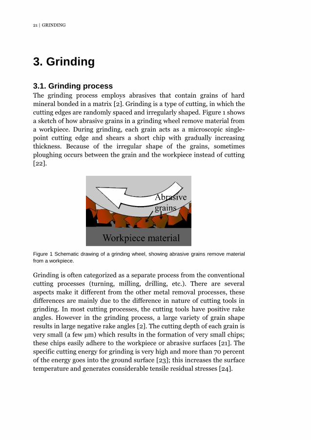
Grinding process 3.1.The grinding process employs abrasives that contain grains of hard
mineral bonded in a matrix [2]. Grinding is a type of cutting, in which the
cutting edges are randomly spaced and irregularly shaped. Figure 1 shows
a sketch of how abrasive grains in a grinding wheel remove material from
a workpiece. During grinding, each grain acts as a microscopic single-
point cutting edge and shears a short chip with gradually increasing
thickness. Because of the irregular shape of the grains, sometimes
ploughing occurs between the grain and the workpiece instead of cutting
[22].
Figure 1 Schematic drawing of a grinding wheel, showing abrasive grains remove material
from a workpiece.
Grinding is often categorized as a separate process from the conventional
cutting processes (turning, milling, drilling, etc.). There are several
aspects make it different from the other metal removal processes, these
differences are mainly due to the difference in nature of cutting tools in
grinding. In most cutting processes, the cutting tools have positive rake
angles. However in the grinding process, a large variety of grain shape
results in large negative rake angles [2]. The cutting depth of each grain is
very small (a few µm) which results in the formation of very small chips;
these chips easily adhere to the workpiece or abrasive surfaces [21]. The
specific cutting energy for grinding is very high and more than 70 percent
of the energy goes into the ground surface [23]; this increases the surface
temperature and generates considerable tensile residual stresses [24].

GRINDING | 22
Grinding fluid is sometimes used to cool the material and abrasives, to
reduce the interface friction between the workpiece and the abrasive
grains, and to remove the chips and reduce adhesion of chips. The choice
of lubricant depends largely on the workpiece material [2].
Residual stresses in grinding 3.2.During grinding, mechanical and thermal actions between the workpiece
material and the abrasive grains happen simultaneously. As illustrated in
Figure 2, the sources for these actions mainly include five parts:
deformation from shearing zone, friction from rake face, cutting-off work
from cutting edge, friction from the flank and friction from bonding.
Figure 2 Sources of mechanical and thermal actions in grinding: (1) deformation from
shearing zone, (2) friction from rake face, (3) cutting-off work from cutting edge, (4) friction
from flank, (5) friction from bond; modified from [25].
The residual stress in grinding is governed by the complex coupling of
both mechanical and thermal actions; the relative significance of these
two factors varies from one process to another [24] [26]. Depending on
the plastic deformation mode, tension or compression, mechanically
induced residual stresses can be either tensile or compressive. In the
grinding direction, the surface layer experiences overall compressive
plastic deformation, the constraint by the subsurface results in tensile
residual stresses in the surface layer [27]. In the transverse direction,
tensile deformation is dominant. Surface compressive stresses are
generated due to the interaction between the surface layer and the bulk
[28]. However, thermally induced residual stresses are usually tensile.
Thermal actions generate heat in the surface layer, thus a temperature

23 | GRINDING
gradient is formed from surface to the bulk. After the grinding zone
moves away, contraction of the surface layer will be hindered by the low
temperature bulk, thus tensile residual stresses are generated in both
directions during the cooling period [25] [29]. Other thermal impacts
such as phase transformation or dynamic recrystallization can also induce
residual stresses due to structure alteration and volume change of the
surface layer material [28]. The size and depth of residual stresses
induced by both mechanical and thermal actions depend largely on the
cutting and frictional conditions between the abrasive and the workpiece
material [30].
Published work on grinding 3.3.Grinding has great importance in the steel industry. It is widely used as
surface finishing process to get the precise dimension of the component,
although sometimes it is also used as bulk removal. The performance of
grinding has been proved to be largely influenced by the settings of the
operation, such as abrasive grit material [24], workpiece material [21],
abrasive grit size [31], abrasive grain shape [32] and grain rake angle [22],
grinding depth [24], grinding speed [22], feed rate [28], grinding
lubricant [33] and etc. However, compared with other machining process,
relatively little work has been published on grinding, especially in
grinding stainless steels with well controlled grinding parameters.
SURFACE INTEGRITY | 24
4. Surface integrity
A good understanding of the changes in the surface layer is required to
improve the product quality. Typical surface alternations include
topological (geometric), metallurgical, mechanical, chemical and other
changes [34]. The concept of surface integrity was first introduced in a
technical sense by Field and Kahles [35]; they defined it as the ‘inherent
or enhanced condition of a surface produced by machining processes or
other surface generation operations’. Their subsequent comprehensive
review of surface integrity issues of various alloys from machining
processes is among the first published literature on this topic, and this
work emphasized the metallurgical alterations [36]. They later also
provided a detailed description of measuring methods available for
surface integrity inspection as well as an experimental procedure for
assessing surface integrity parameters [37]. Their pioneering work made
a significant contribution to the subject, which led to the subsequent
establishment of an American National Standard on Surface Integrity
[38]. In modern manufacturing processes, special knowledge and analysis
of surface integrity can effectively assist in optimization and adaptive
control, give a good compromise between the function of the surface and
the minimization of production time and cost.
Surface roughness 4.1.Surface roughness is the foremost characteristic of surface integrity issues
caused by machining tools used in the process. Roughness is the primary
indicator related to the machinability of the workpiece material, the
machining conditions, the tool form, the tolerance requirements and the
tribological phenomena of the technological surfaces [25]. Furthermore,
achieving a desired surface roughness is also critical in determining the
service performance of the machined component. Reduced stress
corrosion cracking resistance of X70 gas pipelines was observed with
increased surface roughness [39]. Micro-notches induced by machining
will generate a localized plastic strain field when a stress is applied, due to
stress concentration at the notch tip; so fatigue cracks and stress
corrosion cracks are prone to initiate in this zone of plasticity [40] [41].
Fatigue micro-cracks have been suggested to initiate from persistent slip
bands or grain boundaries instead of the surface of machined specimens
with low surface roughness [42]. The effect of surface roughness on the
25 | SURFACE INTEGRITY
component’s life performance can also be correlated to other factors.
Stress corrosion crack concentration has been reported to increase with
increasing surface roughness, which may be related to the concentration
of surface damage and hence potential initiation sites for cracks to
nucleate [39]. Due to the higher tensile residual stresses combined with
applied stress, pitting has been reported to be most significant on the
ground surface despite a much low Ra value compared to the milled
samples [19]. When machining stainless steels, surface roughness of the
workpiece material is largely affected by the machining method and the
parameters used [43] [44] [45].
Surface defects 4.2.Different forms of defects can be left on the surface after the machining
process. Waviness, grooves, smearing, chip re-deposition, feed marks,
cavities and cracks are the ones most often observed on the machined
surfaces [25]. Problems can be caused from the surface defects during the
service. A greater propensity for pitting has been reported at local defect
sites on the machined surfaces [19] [46], and these pits were found to act
as precursors to cracks. Failure at small grinding defects has been
observed as predominant failure mode of a clean spring steel in the very
high cycle fatigue regime [47]. A complete elimination of surface defects
of a machined component is not possible; but based on the properties of
the material, these defects can be reduced by choosing the proper
machining parameters [48].
Microstructural alterations 4.3.The main surface damage of a machined component comes from
mechanical loading and thermal impact which occur simultaneously
during the machining operations. Both are all strongly influenced by the
machining parameters. Microstructural alterations of the machined
surfaces, such as deformation hardening [34], phase transformation [20],
grain fragmentation [49], white layer formation [50], grain
recrystallization [51], are result from these effects. The properties of the
machined components are closely related to the microstructure of the
surface layer. An increased hardness of the surface has been reported,
and a work hardened surface layer can increase the difficulty for the
subsequent cutting of materials with high work hardening rate [52]. The
presence of strain induced martensite on the surface from machining has

SURFACE INTEGRITY | 26
been shown to increase the SCC susceptibility of 304L austenitic stainless
[49]. The improvement of stress corrosion cracking resistance by grain
refinement from laser peening of 304 austenitic stainless steel has been
demonstrated [53]. The white layer is normally hard and brittle, cracks
were found to easily nucleate and propagate in the surface white layer
[54].
Residual stresses 4.4.Residual stresses are stresses that remain in the material after the
original cause has been removed; they can arise in almost every step of
processing [27]. Although residual stresses can have different origins
such as mechanical, thermal or metallurgical causes, they are all the
results of misfit; these misfits can be between different regions, different
parts, or different phases [55]. Residual stresses may be desirable or
undesirable. Depending on the workpiece material and the machining
processes, both tensile and compressive residual stresses with varied
magnitude can be generated in the surface and subsurface layers of the
component [56] [57]. Surface compressive residual stresses are generally
considered to be beneficial for the life performance of a component; while
surface tensile residual stresses should be avoided. Multiple and
interacting cracks have been reported on the milled surface of AISI 316
after exposure in boiling magnesium chloride for two weeks without
applying any external load; the main driving force for the crack formation
has been demonstrated to be the surface tensile residual stresses from the
milling operations [58]. The compress residual stresses from massive
laser peening of AISI 304 have been shown to have a beneficial effect on
the stress corrosion cracking resistance [53]. Another problem that can
be caused by the residual stresses is the dimensional instability; a change
in dimension with time of a machined component may cause problems in
structural assembling [59].

27 | CORROSION OF STAINLESS STEELS
5. Corrosion of stainless steels
If the environment is too harsh, stainless steels can suffer from several
types of corrosion, such as uniform corrosion, crevice corrosion, pitting,
stress corrosion cracking, intergranular corrosion, galvanic corrosion and
corrosion fatigue [10]. Below, two types of corrosion that are relevant to
this work are discussed.
Pitting corrosion 5.1.Pitting corrosion is a localized form of attack at small discrete areas. Pits
can look quite small at the surface and be hidden by apparently
inoffensive corrosion products, but they may have larger area beneath the
surface; thus pitting can remain undiscovered until failure [10]. Pitting
results from a failure of the passive layer and the mechanisms of this pit
initiation have been widely discussed but still not fully understood. The
main mechanisms proposed are the penetration mechanism, the film-
breaking mechanism and the adsorption mechanism [60]. The
penetration mechanism involves the transport of anions through the
oxide film to the metal surface where they start specific actions. For the
film-breaking mechanism, rupture of the passive film gives direct access
of the anions to the bare metal surface. The absorption mechanism begins
with the adsorption of aggressive anions at the oxide surface, thus the
metal cations from the oxide are catalytically enhanced to transfer to the
electrolyte, leading to the thinning of passive film until total removal.
In contrast, the propagation of pitting is relatively well understood. Once
the pit nucleates, the unprotected metal becomes anode and the
surrounding environment acts as cathode, so a galvanic cell is formed. If
no repassivation takes place, the large cathode-to-anode surface ratio will
result in rapid local corrosion [10]. As the pit continues to grow, the pH
value in the pit will decrease due to the hydrolysis of dissolved metal ions;
this in turn further concentrates anions such as chloride ions in the pit [4];
the environment inside the growing pit becomes more aggressive and
repassivation becomes even less likely, thus pits often propagate at a high
rate. The mechanisms for pit initiation and propagation are illustrated in
Figure 3.

CORROSION OF STAINLESS STEELS | 28
Figure 3 Schematic drawing of the pit initiation and propagation mechanisms.
For stainless steels, the pitting resistance equivalent (PRE) is often used
as an index for ranking resistance to pitting corrosion. In general, the
higher the PRE value, the better the resistance to pitting. "Super" is often
used as a descriptor for an alloy with PRE value above 40, such as
superaustenitic or superduplex stainless steels. PRE is calculated from
the chemical compositions of stainless steels [10]:
PRE = %Cr + 3.3 × %Mo + 16 × %N 5.1
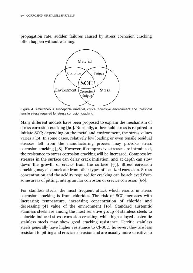
Stress corrosion cracking 5.2.Stress corrosion cracking (SCC) is a brittle failure caused by the
interaction of three factors: a susceptible alloy, a corrosive environment
and the presence of sufficient tensile stresses (Figure 4) [4]. Cracks may
be transgranular or intergranular depending on the microstructure of the
material and the nature of the environment [4]. Due to the high
29 | CORROSION OF STAINLESS STEELS
propagation rate, sudden failures caused by stress corrosion cracking
often happen without warning.
Figure 4 Simultaneous susceptible material, critical corrosive environment and threshold
tensile stress required for stress corrosion cracking.
Many different models have been proposed to explain the mechanism of
stress corrosion cracking [60]. Normally, a threshold stress is required to
initiate SCC; depending on the metal and environment, the stress values
varies a lot. In some cases, relatively low loading or even tensile residual
stresses left from the manufacturing process may provoke stress
corrosion cracking [58]. However, if compressive stresses are introduced,
the resistance to stress corrosion cracking will be increased. Compressive
stresses in the surface can delay crack initiation, and at depth can slow
down the growth of cracks from the surface [53]. Stress corrosion
cracking may also nucleate from other types of localized corrosion. Stress
concentration and the acidity required for cracking can be achieved from
some areas of pitting, intergranular corrosion or crevice corrosion [60].
For stainless steels, the most frequent attack which results in stress
corrosion cracking is from chlorides. The risk of SCC increases with
increasing temperature, increasing concentration of chloride and
decreasing pH value of the environment [10]. Standard austenitic
stainless steels are among the most sensitive group of stainless steels to
chloride-induced stress corrosion cracking, while high-alloyed austenitic
stainless steels may show good cracking resistance. Ferritic stainless
steels generally have higher resistance to Cl-SCC; however, they are less
resistant to pitting and crevice corrosion and are usually more sensitive to
CORROSION OF STAINLESS STEELS | 30
hydrogen-related cracking. Duplex stainless steels with a combination
microstructure of austenite and ferrite have much better Cl-SCC
resistance than that of the classic austenitic grades [61].
There are different ways to evaluate the stress corrosion cracking
susceptibility of stainless steels. There are a number of standardized
testing environments, including boiling ~45% (by weight) aqueous
magnesium chloride solution at 155.0 ± 1.0℃ according to ASTM G36 [62]
and boiling 25% (by mass) sodium chloride acidified to pH 1.5 at ~108℃
standardized in ASTM G123 [63]. In addition, SCC tests can be done
under constant strain or constant load conditions described by ISO and
ASTM standards. Bent-beam [64], U-bend [65], C-ring [66], slow strain
rate [67] are all widely used. The method chosen is critical to the outcome
of the test; since corrosion behaviour can vary a great deal with different
testing conditions [61] [68].

31 | EXPERIMENTAL WORK
6. Experimental work
Materials 6.1.Two grades of stainless steels, austenitic 304L and duplex 2304, have
been used in the current work. The austenitic grade is very widely used
for many applications, while duplex stainless steels are newer alternatives
with the attractive property of higher strength. The materials were
industrially produced in Outokumpu Stainless AB, and they were
delivered in the form of test coupons with dimensions
400mm×150mm×2mm. The as-delivered materials had been solution
annealed (1100℃, forced air and water quenched), thereafter pickled and
roll leveled. EBSD mapping showing the microstructure of the two
materials are presented in Figure 5. The chemical compositions in wt%
and the mechanical properties measured perpendicular to the rolling
direction at room temperature are given in Table 1 and Table 2,
respectively. Both duplex stainless steel 2304 (Paper I) and austenitic
stainless steel 304L (Paper II) were used for surface integrity studies. For
the corrosion studies (Paper III), the austenitic 304L stainless steel was
used.
Figure 5 Cross-section microstructure of: (a) 304L austenitic stainless steel showing grain
orientation, (b) 2304 duplex stainless steel showing red austenitic phase and blue ferritic
phase.
Table 1 Chemical composition (wt%, Fe-balance) of the stainless steels investigated.
Grade In paper C Si Mn P S Cr Ni Mo Nb N Cu Co Ti
2304 I 0.019 0.39 1.48 0.028 0.001 23.35 4.84 0.36 - 0.125 0.22 - 0.006
304L II, III 0.019 0.32 1.55 0.029 0.001 18.22 8.11 - 0.011 0.071 0.31 0.16 -

EXPERIMENTAL WORK | 32
Table 2 Mechanical properties of the stainless steels measured perpendicular to the rolling
direction at room temperature.
Grade In paper Rp0.2(MPa) Rm(MPa) Elongation (%) Hardness (HB)
2304 I 590 739 30 228
304L II, III 230 642 54 170
Grinding operations 6.2.The grinding operations were conducted on a Chevalier FSG-2A618
grinding machine; the set-up is shown in Figure 6. A Kemper RADIX Go
grinding wheel (50mm in width, 150mm in diameter), which is an
expanding roller made of 20mm thick rubber, was used. During grinding,
grinding belts (50mm in width, 473mm in length) with conventional
aluminum oxide grit were mounted on the grinding wheel and test
coupons (400mm×150mm×2mm) were mounted on the working table. A
fixed grinding speed vs = 23m/s and a fixed feed rate vw = 8m/s were
used. All grinding operations were performed along the rolling direction
of the workpiece material.
Figure 6 The grinding set-up.
Both duplex 2304 and austenitic 304L stainless steels were ground; an
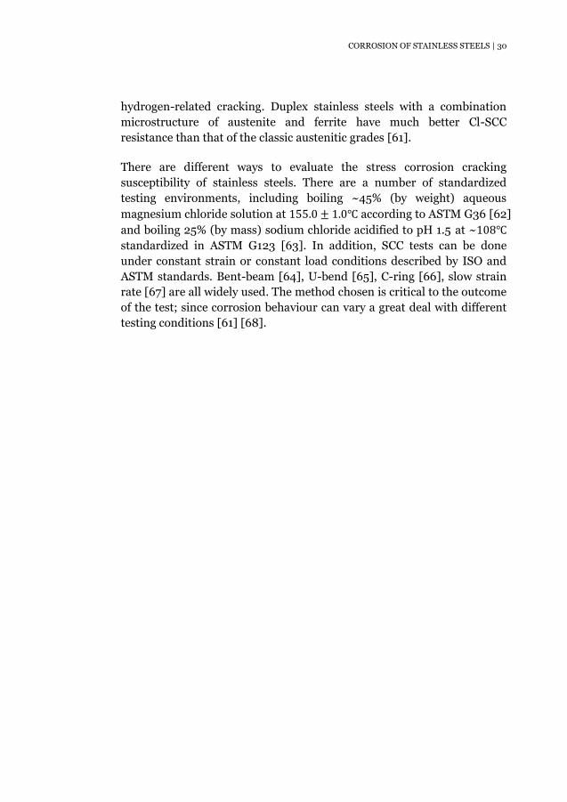
overview of the grinding parameters used is given in Table 3. Grinding
parameters that were varied were abrasive grit size, machine power and
33 | EXPERIMENTAL WORK
grinding lubricant. The machine power denotes the percentage of the
total motor power to drive the grinding belt around; the total motor effect
is 1kW. A piezo-electric transducer based dynamometer Kistler 9257B
(Figure 6) was mounted under the working table to measure the normal
force acting on the contact zone between the abrasive and workpiece
material. During grinding, the grinding force was varied by changing the
machine power; a given machine power was set and the induced normal
grinding force was measured. The grinding lubricant used was Mobilcut
321 of 3% concentration; it is a synthetic fluid with a pH value of 9.4 and
specific gravity of 1.10 at 20℃ . The cooling system of the grinding
machine was cleaned before grinding operations and new lubricant was
used from beginning. During grinding operations, the used lubricant
flowed into a chamber where large chips and particles sink down to the
bottom. The fluid then flowed into a smaller chamber and was pumped
up onto the workpiece surface again. Surface integrity has been
investigated for all the specimens ground with different parameters,
including both duplex 2304 (paper I) and austenitic 304L (paper II)
stainless steels. For the corrosion studies (paper III), only austenitic 304L
grade ground with 60# final surface finish, 60% machine power and
without grinding lubricant was used.
Table 3 Overall view of the grinding parameters.
Group No. Comparison Final surface
finish Machine
power Lubricant
In paper
i Abrasive grit size
60#
60% without
I/II, III
180#
I/II
400#
ii Machine
power 180#
30%
without 60%
90%
iii Lubrication 180# 60% without
with

EXPERIMENTAL WORK | 34
An infrared camera FLIR i5 was used to measure the surface temperature
of the workpiece during grinding; the measuring spots were near the
contact area between the grinding wheel and the workpiece material. The
emissivity setting of the camera was 0.95 both with and without lubricant.
Since temperature measurements are strongly influenced by the surface
conditions and the camera settings, the measured results in this study
only provided an indication of the trends in temperature change with
different grinding parameters.
Corrosion studies 6.3.The purpose of the corrosion tests (paper III) was to determine the
influence of surface grinding on the SCC behaviour. The 304L austenitic
stainless steel ground with 60# final surface finish, 60% machine power
and without grinding lubricant was used. Three types of specimens were
corrosion tested. All specimens were water jet cut from the test coupons.
As illustrated in Figure 7, the specimens cut with the long axis parallel to
the rolling/grinding direction, are denoted ground-RD and transverse to
rolling/grinding direction, are denoted ground-TD. The as-delivered
specimens cut parallel to the rolling direction, denoted AD, were tested as
reference.
Figure 7 Schematic illustration of the orientation and designation of the specimens for
corrosion tests.
Boiling magnesium chloride solution according to ASTM G36 [62] was
used as the test environment. The specimens were exposed in a flask
connected to a water cooled condenser and a thermometer; solution
temperature was carefully maintained at 155 ± 1℃. Before exposure, all

35 | EXPERIMENTAL WORK
the specimen edges were ground down using 800# abrasive paper to
avoid sharp edges. Specimens were then allowed to passivate in air for at
least 24 hours.
The susceptibility to chloride induced stress corrosion cracking was tested
in two ways. The first set of tests was without applying external loading to
investigate the role of residual stresses. All three types of specimens
(dimension 45mm×10mm×2mm) were exposed. After 20 hours, the
specimens were removed and checked for macro-cracks using a stereo
microscope. If no macro-cracks were observed, the specimens were then
put back for another 20h exposure. In the second series of tests, four-
point bend loading (dimension 65mm×10mm×2mm) to different levels
was applied according to ASTM G39 [64]. The loading direction was
along the longitudinal direction. After application of the load, specimens
were kept one hour in air to allow possible stress relaxation before
exposure. In this case, the exposure period was 24 hours.
Characterization techniques 6.4.
6.4.1. 3D optical surface profilometry To get a first impression of the ground surface topography, a Wyko NT
9100 3D optical surface profilometer has been used in the current work.
These measurements result in both 2D and 3D pictures of the surface
morphology as well as some mathematical parameters describing the
surface. This method is rather quick and has a depth resolution of 5nm.
However, the samples have to reflect light; otherwise coating deposition
is required.
From each area (1.3 mm×0.95 mm) of measurement, roughness values,
both Ra and Rz, are calculated. The Ra value is an arithmetic average
roughness, i.e. the arithmetic average value of roughness profile
determined from deviations about the mean line over the evaluation
length [25]. The Rz value is the average peak to valley height [25]; here it
is the difference between the mean value of the five maximum peak
heights and the five minimum valley depths from an arbitrarily chosen
reference line over the measured surface. In the current work, five areas
of each ground samples were measured, and the roughness is the average
of these five measurements.
EXPERIMENTAL WORK | 36
6.4.2. Stereo microscope A Nikon SMZ-2T stereo microscope with ColorView Soft camera and CellA
ColorView Soft image software of ×10-63 magnification was used to check
the presence of macro-cracks in the specimens after exposure. The stereo
microscope is an optical microscope and uses light reflected from the
sample surface rather than transmitted through it [69]. It can provide a
3D visualization of the examined sample. This technique has rather poor
depth resolution but is fast and gives valuable information, such as
whether macro-cracks have been formed and where they are, for more
detailed investigations.
6.4.3. Scanning electron microscopy The possibility to characterize morphology and microstructure with good
resolution at high magnification is of great importance in studies of the
surface integrity and corrosion behaviour. In this work it was made by
using scanning electron microscopy (SEM). By accelerating an electron
beam onto the sample, signals containing different information about the
material investigated can be generated. The electrons in the beam are
emitted from an electron source, which in the instruments used for the
current work is the field emission gun. Each signal comes from particular
interactions between the atoms at/near the sample surface and the
incident electrons. The signals used for this study include secondary
electrons (SE) and backscatter electrons (BSE).
The most common imaging mode uses secondary electrons. SEs are the
ejected electrons from atoms due to the inelastic scattering interactions
between the primary electrons and the valence electrons of the sample
atoms [70]. Generally, all electrons emitted from the specimen with an
energy less than 50eV are considered as secondary electrons [71]. Because
of the low energy of these electrons, only those produced near the surface
of the sample are able to exit and be collected by the detector. The
production of SEs is very dependent on the surface morphology. The SEs
can produce very high resolution images of the sample surface; the
surface sensitivity, signal intensity and resolution can be optimized by
changing the beam current, the working voltage or apertures.
Backscattered electrons are from the primary incident beam that is
ejected back out from the sample; they are used to produce a different

37 | EXPERIMENTAL WORK
kind of image. Compared with SEs, BSEs have higher energy (> 50eV);
therefore they have larger escape depth. So the information they produce
is less restricted to the surface details; however this also results in
reduced resolution. The electron channeling phenomenon was first
discovered by Coates; he found a strong variation in backscattered
electron emission as a function of the relative orientation between the
incident electron beam and the crystal lattice (Figure 8) [72]. Directly
after that, Booker et al. explained Coates’s observation on a theoretical
basis. They noted that for particular orientations, the BSEs intensity
changes sharply; these critical beam-crystal orientations are those which
satisfy the Bragg condition for a given set of lattice planes [73]. They also
outlined the general framework of using electron channeling
phenomenon for dislocations. Now electron channeling contrast imaging
(ECCI) has been successfully used to capture local change in crystal
orientation, deformation, strain field or even individual defects in
crystalline materials [74].
Figure 8 Schematic drawing of the variation in backscattered electron emission as a
function of the relative orientation between the incident electron beam and the crystal lattice
[75].
A Zeiss Ultra 55 field emission gun scanning electron microscope (FEG-
SEM) was used to check the surface morphology of specimens as well as
some fracture surfaces. All the microstructural investigations were
performed in a Hitachi FEG-SEM SU-70 by using the ECCI technique.
Cross-sections of selected specimens after corrosion test from both
longitudinal and transversal directions were also examined.

EXPERIMENTAL WORK | 38
6.4.4. X-ray diffraction A number of techniques are available for measuring residual stresses.
Some are destructive, while others are nondestructive; some have good
spatial resolution, whereas others are restricted to near surface stresses.
In the current work, laboratory X-ray diffraction (XRD) was chosen for
the residual stress measurements.
To make a stress measurement by X-ray diffraction, the orthogonal
coordinate systems should be introduced. As shown in Figure 9, the axes
Si define the specimen coordinate system with S1 and S2 in the specimen
surface. The laboratory coordinate system Li (connected with the
direction of measurement) is defined so that L3 is in the normal direction
to the family of planes (hkl) [76]. The residual stress measurement by
XRD is based on the measurement of variations of the inter-planer
spacing (∆d) of a family of crystallographic planes versus their orientation
(ψ) with regard to the surface of the specimen.
Figure 9 Schematic illustration of the orthogonal coordinate systems used in residual stress
measurement by X-ray diffraction method [76].
Elastic strain εφψ is determined by the variations of the inter-planer
spacing, which is related to the displacement of the diffraction peak
(Bragg angle θ):
εφψ =dφψ−d0
d0=
∆d
d0= −cotθ ∙ ∆θ 6.1
39 | EXPERIMENTAL WORK
Where d0 is the stress free lattice spacing of the measured plane.
This strain can be expressed in terms of εij in the specimen coordinate
system [27]:
εφψ = ε11cos2φsin2ψ + ε12sin2φsin2ψ + ε22sin2φsin2ψ + ε33cos2ψ
+ε13cosφsin2ψ + ε23sinφsin2ψ 6.2
By Hook’s law for isotropic material:
εij =1+v
Eσij − δij
v
E(σ11 + σ22 + σ33) 6.3
Where δij is Kronecker’s delta, which equals to 1 when i = j and 0 when
i ≠ j ; E and v are Young’s modulus of elasticity and Poisson’s ratio,
respectively.
Combining all the three equations above, thus:
dφψ − d0
d0
=1 + v
E(σ11cos2φ + σ12sin2φ + σ22sin2φ − σ33)sin2ψ
+1+v
Eσ33 −
v
E(σ11 + σ22 + σ33)
+1+v
E(σ13cosφ + σ23sinφ) ∙ sin2ψ 6.4
In order to calculate the strains and stresses in the specimen, at least six
independent measurements of inter-planer spacing dφψ in different
directions are required, and in practice more points are measured to
improve the accuracy.
If the stress tensor in the irradiated layer is biaxial (σ33 = 0, and shear
components σ13, σ23 = 0 as well), the ‘sin2ψ method’ [27] is commonly
used. Equation 6.4 becomes
dφψ−d0
d0=
1+v
Eσφsin2ψ −
v
E(σ11 + σ22) 6.5

EXPERIMENTAL WORK | 40
Where σφ is the in-plane stress component along the Sφ direction as
shown in Figure 8 and given by
σφ = σ11cos2φ + σ12sin2φ + σ22sin2φ 6.6
According to equation 6.5, a linear relationship of dφψ vs. sin2ψ is
predicted. The stress in the Sφ direction may be obtained from the slope
of a least-squares line fitted to the data measured at various ψ, if the
elastic constants E, v and the stress free plane spacing d0 are known. In
practice, it is difficult to obtain d0 and therefore the lattice spacing
measured at ψ = 0° is often used for substitution. For a biaxial stress, the
resulted error by this substitution is negligible.
For ground or machined surfaces, due to the presence of shear strains ε13
and ε23, ‘ ψ -splitting’, i.e. a non-linear dφψ vs. sin2ψ plot is common.
Under this circumstance, the Dölle-Hauk method [76] can be used.
Equation 6.1 and 6.2 can be rewritten in the form
dφψ−d0
d0= A + Bsin2ψ + Csinψcosψ 6.7
A = ε33
B = ε11cos2φ + ε22sin2φ − ε33 + (ε12 + ε21)sinφcosφ
C = (ε13 + ε31)cosφ + (ε23 + ε32)sinφ
The dφψ vs. sin2ψ dependence have to be measured in plane by three
azimuths φ = 0°, 45°, 90°. The strain tensors εii and εij can be determined
from the dφψ vs. sin2ψ measurements, and stress tensors σii and σij can
be calculated using Hooke’s law. For this method, the accurate value of
the stress free plane spacing d0 is necessary.
For the residual stress measurement in the current work, Cr-Kα radiation
was used, giving diffraction peak at 2θ~128° for the {220} lattice planes
of the austenitic phase and diffraction peak at 2θ~154° for the {211}
lattice planes of the ferritic phase respectively. Diffraction peaks were
measured at nine ψ-angles (ψ = ±55°, ±35°, ±25°, ±15°, 0°). The Pseud-
41 | EXPERIMENTAL WORK
Voigt Profile [76] was used for peak fitting in order to determine the
diffraction peak position and the Full Width at Half Maximum (FWHM),
which is related to the plastic deformation of the material [77]. Residual
stresses were calculated based on either the sin2ψ method or the Dölle-
Hauk method. The X-ray elastic constants, S1 and 1/2S2, needed for the
stress calculations are -1.2×10⁻⁶MPa−1 and 6×10⁻⁶MPa−1 for austenitic
{220} lattice planes and -1.25×10⁻⁶MPa−1and 5.58×10⁻⁶MPa−1 for ferritic
{211} respectively [78]. In-depth stress profiles were measured for some
selected specimens by using controlled electrolytic polishing to remove
material; no correction was made for the possible stress relaxation due to
material removal by polishing. In addition, in-situ measurements of
surface stresses were also made on 304L specimens subjected to loading
in the same four-point bend fixtures used for the stress corrosion
cracking tests (Paper III). After each step of loading added, the specimens
were kept one hour for stress relaxation, then the actual surface residual
stresses parallel to the loading direction were measured. The loading was
increased in steps to levels of 10, 200, 300 and 500 MPa, calculated
according to ASTM G39 [64]. After the measurements, all specimens
were kept in the holder at 500MPa loading and put in a furnace at 155℃
for 24h; then they were cooled to room temperature in the furnace over
another period of 24h. Surface residual stresses were measured again to
investigate the stress relaxation.
RESULTS AND DISCUSSION | 42
7. Results and discussion
This thesis addresses the interlinked themes of surface integrity (Paper I,
Paper II) and stress corrosion properties (Paper III). A brief overview of
the three papers is presented first, followed by detailed discussions of the
two themes.
Summary of appended papers 7.1.
7.1.1. Paper I Surface integrity of 2304 duplex stainless steel after different grinding
operations
Surface integrity of machined components has significant effect on their
service performance. Paper I investigates the surface and subsurface
changes of duplex stainless steel 2304 induced by grinding operations
using different process parameters. Of the three varied grinding
parameters, abrasive grit size, grinding force and grinding lubrication, the
abrasive grit size was found to have the largest influence. Surface defects,
a highly deformed surface layer and the generated tensile residual
stresses along the grinding direction were found to be the main damages
in the ground surface. Residual stresses were demonstrated to have
different levels in the austenitic and ferritic phases.
7.1.2. Paper II Surface characterization of austenitic stainless 304L after different
grinding operations
Austenitic stainless steel 304L is widely used as structural material. Paper
II studied the grinding processes with regard to the quality of the ground
surfaces. The grinding parameters varied were abrasive grit size, machine
power and grinding lubrication. The induced normal grinding force,
grinding surface temperature and metal removal rate was measured and
surface property changes investigated. The conclusion is that using
smaller grit size abrasive or using grinding lubrication can improve
surface finish and deformation; surface deformation increased when
increasing the machine power but this also decreased surface defects.
43 | RESULTS AND DISCUSSION
Moreover, the metal removal rate was significantly enhanced by using
grinding lubrication.
7.1.3. Paper III Effect of surface grinding on chloride induced SCC of 304L
Paper III characterized the stress corrosion cracking (SCC) susceptibility
of ground 304L austenitic stainless steels in boiling magnesium chloride
and investigated the role of residual stresses induced by grinding
operations on the corrosion behaviour. In-situ measurements of surface
stresses external four point bending were performed to evaluate the
difference between the actual stress and the calculated loading according
to ASTM G39. The results showed micro-cracks initiated in the surface as
a result of high tensile residual stresses originated from the grinding
operations. Due to the anisotropy of residual stress induced by grinding,
susceptibility to Cl-SCC was increased by grinding along the loading
direction while grinding perpendicular to the loading direction improved
SCC resistance. After cracks initiated, relief of surface tensile residual
stresses has been observed; this is likely to arrest microscopic cracks and
inhibit initiation of further cracks.
Influence of grinding on surface integrity 7.2.Surface integrity, expressed in terms of surface roughness, surface
defects, near surface microstructural alterations and residual stresses
after surface grinding, has been studied for both austenitic stainless steel
304L (Paper II, Paper III) and duplex stainless steel (Paper I). For both
materials, the influence of grinding parameters including abrasive grit
size (Group i), machine power (Group ii) and grinding lubricant (Group
iii) has been investigated.
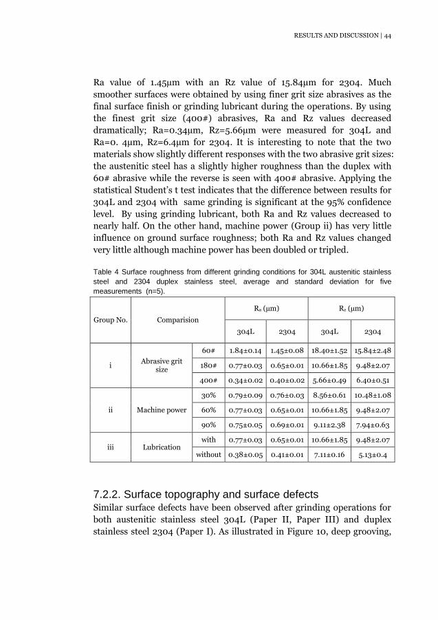
7.2.1. Surface roughness Surface roughness resulting from different grinding parameters was
measured through both Ra and Rz factors which are compared in Table 4;
the trends showed similarity for both 304L (Paper I) and 2304 (Paper II).
From the measured results, most significant parameters are identified as
abrasive grit size (Group i) and grinding lubricant (Group iii). The highest
surface roughness was induced by using coarse grit size (60#) abrasives,
giving an Ra value of 1.81µm with an Rz value of 18.4µm for 304L and an
RESULTS AND DISCUSSION | 44
Ra value of 1.45µm with an Rz value of 15.84µm for 2304. Much
smoother surfaces were obtained by using finer grit size abrasives as the
final surface finish or grinding lubricant during the operations. By using
the finest grit size (400#) abrasives, Ra and Rz values decreased
dramatically; Ra=0.34µm, Rz=5.66µm were measured for 304L and
Ra=0. 4µm, Rz=6.4µm for 2304. It is interesting to note that the two
materials show slightly different responses with the two abrasive grit sizes:
the austenitic steel has a slightly higher roughness than the duplex with
60# abrasive while the reverse is seen with 400# abrasive. Applying the
statistical Student’s t test indicates that the difference between results for
304L and 2304 with same grinding is significant at the 95% confidence
level. By using grinding lubricant, both Ra and Rz values decreased to
nearly half. On the other hand, machine power (Group ii) has very little
influence on ground surface roughness; both Ra and Rz values changed
very little although machine power has been doubled or tripled.
Table 4 Surface roughness from different grinding conditions for 304L austenitic stainless
steel and 2304 duplex stainless steel, average and standard deviation for five
measurements (n=5).
Group No. Comparision
Ra (µm) Rz (µm)
304L 2304 304L 2304
i Abrasive grit
size
60# 1.84±0.14 1.45±0.08 18.40±1.52 15.84±2.48
180# 0.77±0.03 0.65±0.01 10.66±1.85 9.48±2.07
400# 0.34±0.02 0.40±0.02 5.66±0.49 6.40±0.51
ii Machine power
30% 0.79±0.09 0.76±0.03 8.56±0.61 10.48±1.08
60% 0.77±0.03 0.65±0.01 10.66±1.85 9.48±2.07
90% 0.75±0.05 0.69±0.01 9.11±2.38 7.94±0.63
iii Lubrication with 0.77±0.03 0.65±0.01 10.66±1.85 9.48±2.07
without 0.38±0.05 0.41±0.01 7.11±0.16 5.13±0.4
7.2.2. Surface topography and surface defects Similar surface defects have been observed after grinding operations for
both austenitic stainless steel 304L (Paper II, Paper III) and duplex
stainless steel 2304 (Paper I). As illustrated in Figure 10, deep grooving,

45 | RESULTS AND DISCUSSION
smearing, adhesive chips and indentations are the four types of defects
found on the ground surfaces. The ground surface finish was influenced
by the complex interactions between the abrasive grits and the workpiece
surface. Deep grooving came from the uneven metal removal process,
including chip forming and ploughing. Material around abrasive grit
particles was pushed out and moved across the surface, which led to the
formation of smearing areas. The redeposition process [22] introduced
adhesive chips; the chips were transferred to the abrasive grit particles by
adhesion, and then were transferred back to the ground surface by
friction welding. Abrasive particles broke down into small pieces during
grinding; because of the rubbing contact between these broke down
particles or formed chips and the workpiece surface, indentations were
formed on the ground surfaces.
Figure 10 Surface topography and surface defects after grinding by 60# grit size abrasive,
60% machine power and without lubricant: (a) austenitic stainless steel 304L, (b) duplex
stainless steel 2304.
The abrasive grit size (Group i) and grinding lubricant (Group iii) showed
similar effects on the surface finish for 304L and 2304. The surface finish
was clearly improved by using finer grit size abrasives or grinding
lubricant; the reduction of surface defects was obvious. Smaller size of
abrasive grits with a more even distribution and the largely reduced
friction by lubricant are proposed to be the main factors respectively. On
the other hand, the influence of machine power (Group ii) appeared to be
different for these two materials. For duplex 2304, grinding with the
intermediate machine power (60%) resulted in a better surface finish
than grinding with lower (30%) or higher (90%) machine power. A lower
machine power means a lower normal grinding force, which decreased
cutting and ploughing but increased rubbing; while a higher machine
RESULTS AND DISCUSSION | 46
power means a higher downward force, which increased wear and friction
between the abrasive grit and the workpiece surface. As a result, both
lower and higher machine power generated more smearing areas and
adhesive chips. However, the effect of varied machine power also depends
on the properties of the workpiece material. Clear improvement of
ground surface finish by increasing machine power up to 90% was
observed in 304L. Austenitic stainless steels have high toughness and
high ductility, 304L has been characterized as gummy during machining
[16]. Increased machine power led to higher degree of strain hardening of
the surface, thus the gummy behaviour was reduced and the final surface
finish was improved.
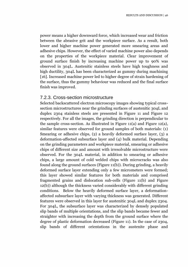
7.2.3. Cross-section microstructure Selected backscattered electron microscopy images showing typical cross-
section microstructures near the grinding surfaces of austenitic 304L and
duplex 2304 stainless steels are presented in Figure 11 and Figure 12
respectively. For all the images, the grinding direction is perpendicular to
the sample cross-section. As illustrated in Figure 11(a) and Figure 12(a),
similar features were observed for ground samples of both materials: (1)
Smearing or adhesive chips, (2) a heavily deformed surface layer, (3) a
deformation-affected subsurface layer and (4) bulk material. Depending
on the grinding parameters and workpiece material, smearing or adhesive
chips of different size and amount with irresolvable microstructure were
observed. For the 304L material, in addition to smearing or adhesive
chips, a large amount of cold welded chips with microcracks was also
found along the ground surfaces (Figure 11(b)). During grinding, a heavily
deformed surface layer extending only a few micrometers were formed;
this layer showed similar features for both materials and comprised
fragmented grains and dislocation sub-cells (Figure 11(b) and Figure
12(b)) although the thickness varied considerably with different grinding
conditions. Below the heavily deformed surface layer, a deformation-
affected subsurface layer with varying thickness was generated. Different
features were observed in this layer for austenitic 304L and duplex 2304.
For 304L, the subsurface layer was characterized by densely populated
slip bands of multiple orientations, and the slip bands became fewer and
straighter with increasing the depth from the ground surface where the
degree of plastic deformation decreased (Figure 11). In the case of 2304,
slip bands of different orientations in the austenite phase and

47 | RESULTS AND DISCUSSION
deformation fringes in the ferritic phase were observed (Figure 12(b))
with the intensity of deformation decreasing with increasing depth from
the ground surface; the different microstructures are due to the different
dislocation slip systems of the two phase during deformation. For all the
ground samples, the grinding affected deformation zone was much
smaller than the abrasive grit particle sizes.
Figure 11 Cross-section microstructure of austenitic stainless steel 304L after grinding by
different grit size abrasives (Group i): (a) 180#, (b) 60#.
Figure 12 Cross-section microstructure of duplex stainless steel 2304 after grinding with
different grit size abrasives (Group i): (a) 60#, (b) 400#.
From the cross-section investigations, the size and amount of ground
surface defects (smearing, adhesive chips and or cold welded chips), as
well as the thickness of deformed surface and subsurface layers,
decreased appreciably when finer grit size abrasives (Group i) were used.
This indicated an improved surface finish and smaller deformation; and
the trend was similar for both 304L and 2304.
Compared with grinding at 60% machine power, both decreasing and
increasing machine power led to a higher generation of defects along the
ground surfaces (Group ii). A lower machine power (30%) means a lower
RESULTS AND DISCUSSION | 48
normal grinding force and less effective metal removal; so abrasive grit
slides over the workpiece surface and can introduce many small smearing
areas and adhesive chips. However, a lower grinding surface temperature
also reduced cold welding chip formation on the ground 304L surfaces
with lower machine power. A higher machine power (90%) increased
friction and wear as well as the grinding surface temperature and as a
result, more smearing areas and cold welded chips were formed. Machine
power was found to have only a small influence on the deformation
intensity and deformation depth for both materials, although
deformation was found to be very uneven when using 30% machine
power.
Using grinding lubricant (Group iii) largely reduced the formation of
surface defects on the ground surfaces for both materials and the
reduction in deformation depth is also obvious; this can be simply
explained by the measured lower grinding surface temperature and lower
normal grinding force. Using lubricant was also found to give more even
deformation.
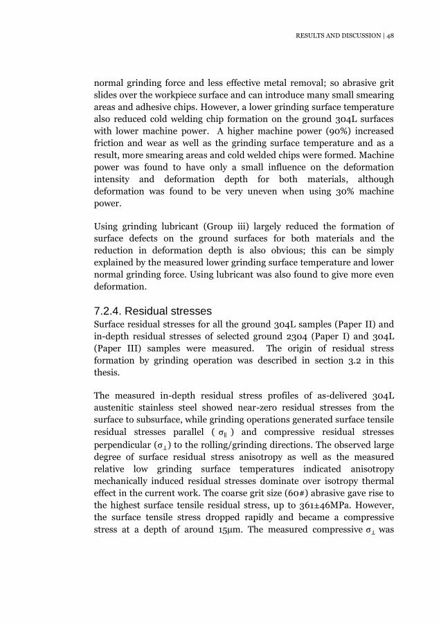
7.2.4. Residual stresses Surface residual stresses for all the ground 304L samples (Paper II) and
in-depth residual stresses of selected ground 2304 (Paper I) and 304L
(Paper III) samples were measured. The origin of residual stress
formation by grinding operation was described in section 3.2 in this
thesis.
The measured in-depth residual stress profiles of as-delivered 304L
austenitic stainless steel showed near-zero residual stresses from the
surface to subsurface, while grinding operations generated surface tensile
residual stresses parallel ( σ∥ ) and compressive residual stresses
perpendicular (σ⊥) to the rolling/grinding directions. The observed large
degree of surface residual stress anisotropy as well as the measured
relative low grinding surface temperatures indicated anisotropy
mechanically induced residual stresses dominate over isotropy thermal
effect in the current work. The coarse grit size (60#) abrasive gave rise to
the highest surface tensile residual stress, up to 361±46MPa. However,
the surface tensile stress dropped rapidly and became a compressive
stress at a depth of around 15µm. The measured compressive σ⊥ was
49 | RESULTS AND DISCUSSION
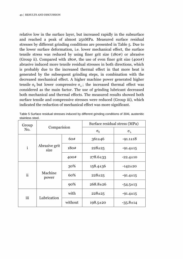
relative low in the surface layer, but increased rapidly in the subsurface
and reached a peak of almost 250MPa. Measured surface residual
stresses by different grinding conditions are presented in Table 5. Due to
the lower surface deformation, i.e. lower mechanical effect, the surface
tensile stress was reduced by using finer grit size (180#) or abrasive
(Group ii). Compared with 180#, the use of even finer grit size (400#)
abrasive induced more tensile residual stresses in both directions, which
is probably due to the increased thermal effect in that more heat is
generated by the subsequent grinding steps, in combination with the
decreased mechanical effect. A higher machine power generated higher
tensile σ∥ but lower compressive σ⊥ ; the increased thermal effect was
considered as the main factor. The use of grinding lubricant decreased
both mechanical and thermal effects. The measured results showed both
surface tensile and compressive stresses were reduced (Group iii), which
indicated the reduction of mechanical effect was more significant.
Table 5 Surface residual stresses induced by different grinding conditions of 304L austenitic
stainless steel.
Group No.
Comparision Surface residual stress (MPa)
σ∥ σ⊥
i Abrasive grit
size
60# 361±46 -91.1±18
180# 228±25 -91.4±15
400# 278.6±33 -22.4±10
ii Machine
power
30% 158.4±36 -142±20
60% 228±25 -91.4±15
90% 268.8±26 -54.5±13
iii Lubrication with 228±25 -91.4±15
without 198.5±20 -35.8±14
RESULTS AND DISCUSSION | 50
Compared with the austenitic 304L, residual stresses in duplex 2304,
which contain two phases, are more complicated. The measured and
calculated results are presented as phase stresses, macro-stress and
micro-stress in the current work. Phase stresses are residual stresses
measured in the austenitic phase (FCC, σγ) and ferritic phase (BCC, σα).
Macro-stresses (σM) are homogeneous residual stresses on a macroscopic
scale along at least one direction [27]. Micro-stresses here are referred to
the stresses balanced between the austenite (σm,γ) and ferrite (σm,α); they
are stresses on a microscopic scale [27]. The macro and micro stresses are
calculated according to the following equations [76]
σM = Vγσγ + (1 − Vγ)σα 7.1
σm,γ = σγ − σM 7.2
σm,α = σα − σM 7.3
where Vγ is the volume fraction of the austenitic phase.
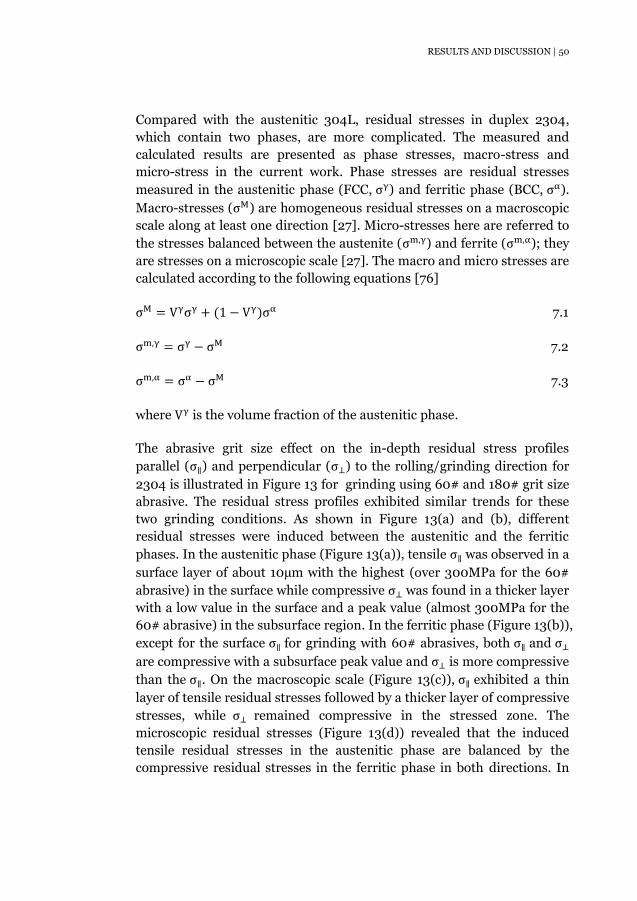
The abrasive grit size effect on the in-depth residual stress profiles
parallel (σ∥) and perpendicular (σ⊥) to the rolling/grinding direction for
2304 is illustrated in Figure 13 for grinding using 60# and 180# grit size
abrasive. The residual stress profiles exhibited similar trends for these
two grinding conditions. As shown in Figure 13(a) and (b), different
residual stresses were induced between the austenitic and the ferritic
phases. In the austenitic phase (Figure 13(a)), tensile σ∥ was observed in a
surface layer of about 10µm with the highest (over 300MPa for the 60#
abrasive) in the surface while compressive σ⊥ was found in a thicker layer
with a low value in the surface and a peak value (almost 300MPa for the
60# abrasive) in the subsurface region. In the ferritic phase (Figure 13(b)),
except for the surface σ∥ for grinding with 60# abrasives, both σ∥ and σ⊥
are compressive with a subsurface peak value and σ⊥ is more compressive
than the σ∥. On the macroscopic scale (Figure 13(c)), σ∥ exhibited a thin
layer of tensile residual stresses followed by a thicker layer of compressive
stresses, while σ⊥ remained compressive in the stressed zone. The
microscopic residual stresses (Figure 13(d)) revealed that the induced
tensile residual stresses in the austenitic phase are balanced by the
compressive residual stresses in the ferritic phase in both directions. In
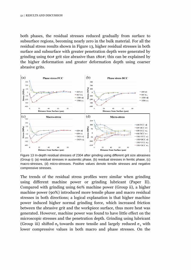
51 | RESULTS AND DISCUSSION
both phases, the residual stresses reduced gradually from surface to
subsurface regions, becoming nearly zero in the bulk material. For all the
residual stress results shown in Figure 13, higher residual stresses in both
surface and subsurface with greater penetration depth were generated by
grinding using 60# grit size abrasive than 180#; this can be explained by
the higher deformation and greater deformation depth using coarser
abrasive grits.
Figure 13 In-depth residual stresses of 2304 after grinding using different grit size abrasives
(Group i): (a) residual stresses in austenitic phase, (b) residual stresses in ferritic phase, (c)
macro-stresses, (d) micro-stresses. Positive values denote tensile stresses and negative
compressive stresses.
The trends of the residual stress profiles were similar when grinding
using different machine power or grinding lubricant (Paper II).
Compared with grinding using 60% machine power (Group ii), a higher
machine power (90%) introduced more tensile phase and macro residual
stresses in both directions; a logical explanation is that higher machine
power induced higher normal grinding force, which increased friction
between the abrasive grit and the workpiece surface, thus more heat was
generated. However, machine power was found to have little effect on the
microscopic stresses and the penetration depth. Grinding using lubricant
(Group iii) shifted σ∥ towards more tensile and largely reduced σ⊥ with
lower compressive values in both macro and phase stresses. On the
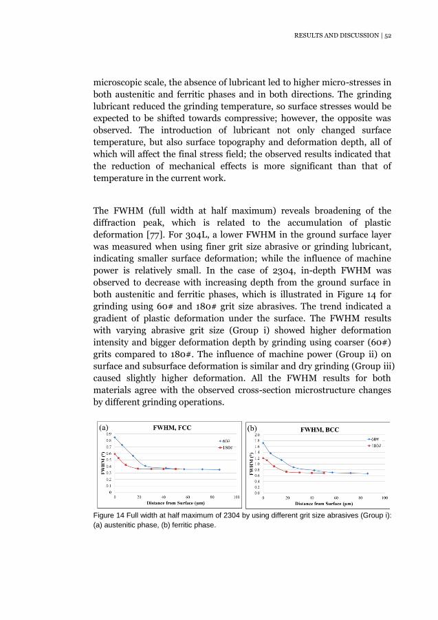
RESULTS AND DISCUSSION | 52
microscopic scale, the absence of lubricant led to higher micro-stresses in
both austenitic and ferritic phases and in both directions. The grinding
lubricant reduced the grinding temperature, so surface stresses would be
expected to be shifted towards compressive; however, the opposite was
observed. The introduction of lubricant not only changed surface
temperature, but also surface topography and deformation depth, all of
which will affect the final stress field; the observed results indicated that
the reduction of mechanical effects is more significant than that of
temperature in the current work.
The FWHM (full width at half maximum) reveals broadening of the
diffraction peak, which is related to the accumulation of plastic
deformation [77]. For 304L, a lower FWHM in the ground surface layer
was measured when using finer grit size abrasive or grinding lubricant,
indicating smaller surface deformation; while the influence of machine
power is relatively small. In the case of 2304, in-depth FWHM was
observed to decrease with increasing depth from the ground surface in
both austenitic and ferritic phases, which is illustrated in Figure 14 for
grinding using 60# and 180# grit size abrasives. The trend indicated a
gradient of plastic deformation under the surface. The FWHM results
with varying abrasive grit size (Group i) showed higher deformation
intensity and bigger deformation depth by grinding using coarser (60#)
grits compared to 180#. The influence of machine power (Group ii) on
surface and subsurface deformation is similar and dry grinding (Group iii)
caused slightly higher deformation. All the FWHM results for both
materials agree with the observed cross-section microstructure changes
by different grinding operations.
Figure 14 Full width at half maximum of 2304 by using different grit size abrasives (Group i):
(a) austenitic phase, (b) ferritic phase.

53 | RESULTS AND DISCUSSION
Influence of grinding on chloride induced SCC 7.3.
7.3.1. Corrosion behaviour without external loading No macro-cracks occurred during exposure in the absence of external
loading for either ground or as-delivered specimens. In the current work,
macro-cracks are defined as those that can be observed by stereo
microscopy with highest magnification of ×63. However, extensive stress
corrosion micro-cracks were observed on all the ground surfaces. Typical
SEM images showing surface morphology after exposure are presented in
Figure 15. As shown in Figure 15(a), the micro-cracks tended to initiate
perpendicular to the grinding direction with branching at angles to the
initial micro-cracks. In the case of as-delivered material (Figure 15(b)),
there is no evidence of such cracking; the slightly etched grain boundaries
were due to the pickling process, which is typical for a 2B surface. A few
small pits were also observed on all specimen surfaces.
Figure 15 Surface morphology after exposure without external loading: (a) ground-RD
specimen, (b) as-delivered specimen.
As illustrated in Figure 16, which are ECC images of the cross-section
microstructures, micro-cracks in absence of external loading appeared
mainly perpendicular to the grinding direction (Figure 16(a)); while along
the grinding marks (Figure 16(b)), only small points of attack, which had
not developed into cracks, were seen. The results agree well with the
surface morphology investigations. High levels of surface tensile residual
stress, up to 350MPa, were measured parallel to the grinding direction
and surface compression in the perpendicular direction. The results
strongly indicated that surface residual tensile stresses made 304L
austenitic stainless steel prone to Cl-SCC even without external loading
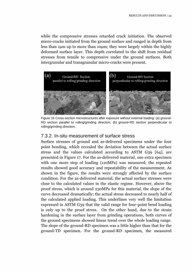
RESULTS AND DISCUSSION | 54
while the compressive stresses retarded crack initiation. The observed
micro-cracks initiated from the ground surface and ranged in depth from
less than 1µm up to more than 10µm; they were largely within the highly
deformed surface layer. This depth correlated to the shift from residual
stresses from tensile to compressive under the ground surfaces. Both
intergranular and transgranular micro-cracks were present.
Figure 16 Cross-section microstructures after exposure without external loading: (a) ground-
RD section parallel to rolling/grinding direction, (b) ground-RD section perpendicular to
rolling/grinding direction.
7.3.2. In-situ measurement of surface stress Surface stresses of ground and as-delivered specimens under the four
point bending, which revealed the deviation between the actual surface
stress and the values calculated according to ASTM G39 [64], are
presented in Figure 17. For the as-delivered material, one extra specimen
with one more step of loading (110MPa) was measured; the repeated
results showed good accuracy and repeatability of the measurement. As
shown in the figure, the results were strongly affected by the surface
condition. For the as-delivered material, the actual surface stresses were
close to the calculated values in the elastic regime. However, above the
proof stress, which is around 230MPa for this material, the slope of the
curve decreased dramatically; the actual stress decreased to nearly half of
the calculated applied loading. This underlines very well the limitation
expressed in ASTM G39 that the valid range for four-point bend loading
is only up to the proof stress. On the other hand, due to the strain
hardening in the surface layer from grinding operations, both curves of
the ground specimens showed linear trend over the whole loading range.
The slope of the ground-RD specimen was a little higher than that for the
ground-TD specimen. For the ground-RD specimen, the measured
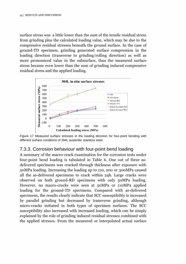
55 | RESULTS AND DISCUSSION
surface stress was a little lower than the sum of the tensile residual stress
from grinding plus the calculated loading value, which may be due to the
compressive residual stresses beneath the ground surface. In the case of
ground-TD specimen, grinding generated surface compression in the
loading direction (transverse to grinding/rolling direction) as well as
more pronounced value in the subsurface, thus the measured surface
stress became even lower than the sum of grinding induced compressive
residual stress and the applied loading.
Figure 17 Measured surface stresses in the loading direction for four-point bending with
different surface conditions of 304L austenitic stainless steel.
7.3.3. Corrosion behaviour with four-point bend loading A summary of the macro-crack examination for the corrosion tests under
four-point bend loading is tabulated in Table 6. One out of three as-
delivered specimens was cracked through thickness after exposure with
50MPa loading. Increasing the loading up to 110, 200 or 300MPa caused
all the as-delivered specimens to crack within 24h. Large cracks were
observed on both ground-RD specimens with only 50MPa loading.
However, no macro-cracks were seen at 50MPa or 110MPa applied
loading for the ground-TD specimens. Compared with as-delivered
specimens, the results clearly indicate that SCC susceptibility is increased
by parallel grinding but decreased by transverse grinding, although
micro-cracks initiated in both types of specimen surfaces. The SCC
susceptibility also increased with increased loading, which can be simply
explained by the role of grinding induced residual stresses combined with
the applied stresses. From the measured or interpolated actual surface

RESULTS AND DISCUSSION | 56
stresses (Table 6), there seems to be a threshold stress of around 50MPa
for the micro-cracks to occur for this material.
Table 6 Macro- and micro-crack examination after exposure with four-point bend loading;
the measured or interpolated surface stresses from Figure 16 are also included for
comparison.
Specimen
Applied four-point
bend loading (MPa)
Measured (or interpolated) surface stress
(MPa)
Exposure time
No. of specimens
tested
No. of exposed
specimens with
macro-cracks
Micro-cracks
As-delivered
50 (20), (50)
24h
3 1 No
110 100 2 2 No
200 126, 166 2 2 No
300 177, 202 2 2 No
Ground-RD
50 (400) 2 2 Yes
300 607 2 2 Yes
Ground-TD 50 (35) 2 0 Yes
110 (70) 2 0 Yes
Surface morphology investigations of all the exposed specimens showed
macro-cracks to exhibit similar features. Multiple cracks with one major
crack through the specimen usually appeared when cracking occurred.
The cracks were perpendicular to the loading direction and tended to run
parallel to each other. Example of surface morphologies after exposure
with 50MPa four-point bend loading of the three types of specimens can
be seen in Figure 18. The macro-cracks appeared to be wide and exhibited
multiple branching (Figure 18(a), (c)). For the ground surfaces, micro-
cracks with extensive branching were also observed without external
loading and tended to be orientated perpendicular to the grinding
direction. This applied even for the ground-TD specimens, indicating the
residual stress effect outweighed the applied load effect and the possible
micro-notch effect from the grinding marks within the experiment range
investigated (applied load ≤ 110MPa). Varying degrees of pitting were
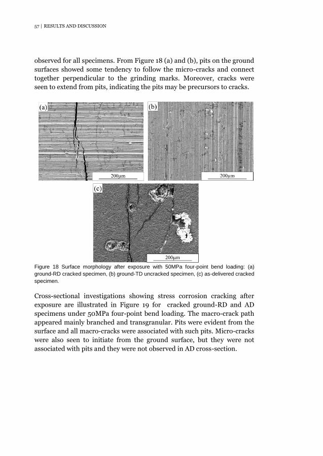
57 | RESULTS AND DISCUSSION
observed for all specimens. From Figure 18 (a) and (b), pits on the ground
surfaces showed some tendency to follow the micro-cracks and connect
together perpendicular to the grinding marks. Moreover, cracks were
seen to extend from pits, indicating the pits may be precursors to cracks.
Figure 18 Surface morphology after exposure with 50MPa four-point bend loading: (a)
ground-RD cracked specimen, (b) ground-TD uncracked specimen, (c) as-delivered cracked
specimen.
Cross-sectional investigations showing stress corrosion cracking after
exposure are illustrated in Figure 19 for cracked ground-RD and AD
specimens under 50MPa four-point bend loading. The macro-crack path
appeared mainly branched and transgranular. Pits were evident from the
surface and all macro-cracks were associated with such pits. Micro-cracks
were also seen to initiate from the ground surface, but they were not
associated with pits and they were not observed in AD cross-section.
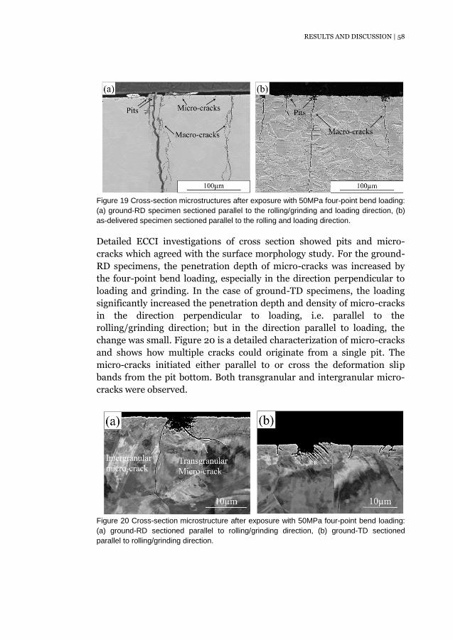
RESULTS AND DISCUSSION | 58
Figure 19 Cross-section microstructures after exposure with 50MPa four-point bend loading:
(a) ground-RD specimen sectioned parallel to the rolling/grinding and loading direction, (b)
as-delivered specimen sectioned parallel to the rolling and loading direction.
Detailed ECCI investigations of cross section showed pits and micro-
cracks which agreed with the surface morphology study. For the ground-
RD specimens, the penetration depth of micro-cracks was increased by
the four-point bend loading, especially in the direction perpendicular to
loading and grinding. In the case of ground-TD specimens, the loading
significantly increased the penetration depth and density of micro-cracks
in the direction perpendicular to loading, i.e. parallel to the
rolling/grinding direction; but in the direction parallel to loading, the
change was small. Figure 20 is a detailed characterization of micro-cracks
and shows how multiple cracks could originate from a single pit. The
micro-cracks initiated either parallel to or cross the deformation slip
bands from the pit bottom. Both transgranular and intergranular micro-
cracks were observed.
Figure 20 Cross-section microstructure after exposure with 50MPa four-point bend loading:
(a) ground-RD sectioned parallel to rolling/grinding direction, (b) ground-TD sectioned
parallel to rolling/grinding direction.
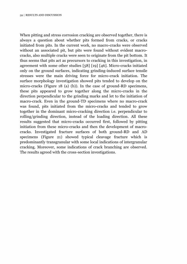
59 | RESULTS AND DISCUSSION
When pitting and stress corrosion cracking are observed together, there is
always a question about whether pits formed from cracks, or cracks
initiated from pits. In the current work, no macro-cracks were observed
without an associated pit, but pits were found without evident macro-
cracks, also multiple cracks were seen to originate from the pit bottom. It
thus seems that pits act as precursors to cracking in this investigation, in
agreement with some other studies [58] [19] [46]. Micro-cracks initiated
only on the ground surfaces, indicating grinding-induced surface tensile
stresses were the main driving force for micro-crack initiation. The
surface morphology investigation showed pits tended to develop on the
micro-cracks (Figure 18 (a) (b)). In the case of ground-RD specimens,
these pits appeared to grow together along the micro-cracks in the
direction perpendicular to the grinding marks and let to the initiation of
macro-crack. Even in the ground-TD specimens where no macro-crack
was found, pits initiated from the micro-cracks and tended to grow
together in the dominant micro-cracking direction i.e. perpendicular to
rolling/grinding direction, instead of the loading direction. All these
results suggested that micro-cracks occurred first, followed by pitting
initiation from these micro-cracks and then the development of macro-
cracks. Investigated fracture surfaces of both ground-RD and AD
specimens (Figure 21) showed typical cleavage fracture which is
predominantly transgranular with some local indications of intergranular
cracking. Moreover, some indications of crack branching are observed.
The results agreed with the cross-section investigations.
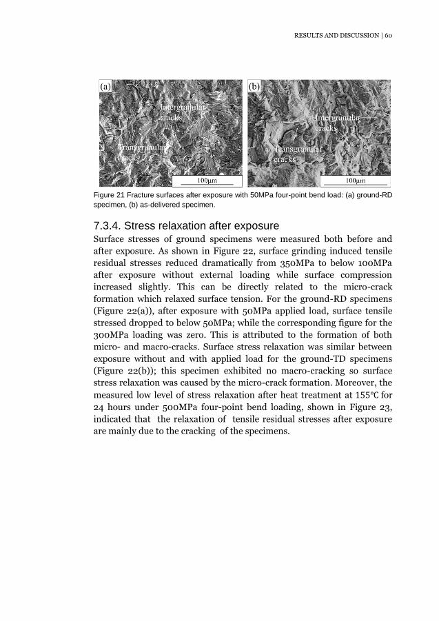
RESULTS AND DISCUSSION | 60
Figure 21 Fracture surfaces after exposure with 50MPa four-point bend load: (a) ground-RD
specimen, (b) as-delivered specimen.
7.3.4. Stress relaxation after exposure Surface stresses of ground specimens were measured both before and
after exposure. As shown in Figure 22, surface grinding induced tensile
residual stresses reduced dramatically from 350MPa to below 100MPa
after exposure without external loading while surface compression
increased slightly. This can be directly related to the micro-crack
formation which relaxed surface tension. For the ground-RD specimens
(Figure 22(a)), after exposure with 50MPa applied load, surface tensile
stressed dropped to below 50MPa; while the corresponding figure for the
300MPa loading was zero. This is attributed to the formation of both
micro- and macro-cracks. Surface stress relaxation was similar between
exposure without and with applied load for the ground-TD specimens
(Figure 22(b)); this specimen exhibited no macro-cracking so surface
stress relaxation was caused by the micro-crack formation. Moreover, the
measured low level of stress relaxation after heat treatment at 155℃ for
24 hours under 500MPa four-point bend loading, shown in Figure 23,
indicated that the relaxation of tensile residual stresses after exposure
are mainly due to the cracking of the specimens.

61 | RESULTS AND DISCUSSION
Figure 22 Surface residual stresses of ground specimens parallel and perpendicular to
rolling/grinding directions before and after exposure: (a) ground-RD specimen, (b) ground-
TD specimen.
Figure 23 Stress relaxation of four-point bend specimens after heat treatment at 155℃ for
24h for AD and ground specimens.
In-depth residual stress profiles of a ground-specimen before and after
exposure without external loading as well as the in-depth surface
morphology after exposure are presented in Figure 24. Results showed
that after exposure the tensile stress dropped from the surface to the
subsurface until reaching a near-zero state where almost all the micro-
cracks stopped. This indicates that micro-cracks initiated due to the high
level of surface residual stresses; that their formation largely released the
surface tensile stress and that they stopped when there was no longer an
acting tensile stress. In-depth surface morphology showed penetration
depths of micro-cracks are very uneven; some of them disappeared after
surface polishing of 2µm in thickness, while some penetrated to a depth
over 10µm. The results agreed with the cross-section observation.
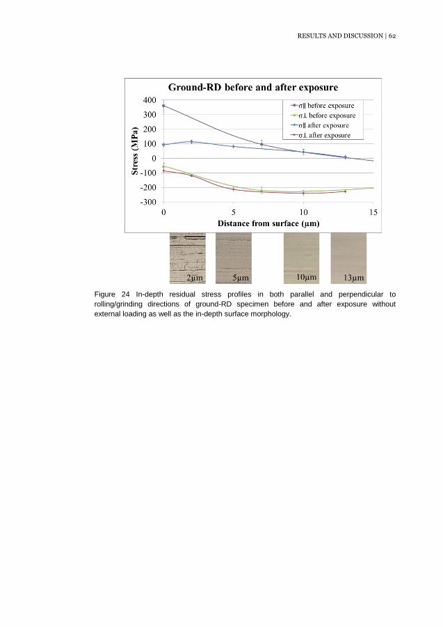
RESULTS AND DISCUSSION | 62
Figure 24 In-depth residual stress profiles in both parallel and perpendicular to
rolling/grinding directions of ground-RD specimen before and after exposure without
external loading as well as the in-depth surface morphology.

63 | CONCLUSIONS
8. Conclusions
This work has addressed some aspects of the interplay between grinding
operations, surface integrity and stress corrosion properties for stainless
steels, following conclusions can be drawn:
Surface roughness and surface defects can be largely decreased by
using smaller grit size abrasives or by using grinding lubricant for
both austenitic stainless steel 304L and duplex stainless steel 2304.
The influence of machine power on surface roughness was small.
Surface defects can be reduced by using a higher machine power
for 304L; however, for 2304, there was an optimum value below or
above which the surface defects became more pronounced.
Microstructure investigations of both 304L and 2304 indicate that
the cross-section of the ground stainless steel samples can be
divided into four layers: a surface layer with smearing, adhesive
chips or cold welded chip, a heavily deformed surface layer, a
deformation affected subsurface layer and the bulk material. The
thickness of each layer varied depending on the grinding
parameters used.
Grinding 304L or 2304 resulted in high level of tensile residual
stresses along the grinding direction and compressive residual
stresses perpendicular to the grinding direction in the surface layer.
Beneath the ground surface, a subsurface layer of compressive
residual stresses in both directions were formed. The residual
stress level depended on the grinding condition. The pronounced
anisotropy of the residual stresses in the current work indicated
that mechanical effects dominated over thermal effects from
heating of the workpiece, since the latter would be expected to be
isotropic.
For the duplex 2304, grinding generated different levels of residual
stresses in the two phases with tensile micro-stresses in the
austenitic and compressive micro-stresses in the ferritic phase.
In-situ surface stress measurements of 304L under four-point
bend loading demonstrated that the actual load may deviate from
the calculated value using the formula according to ASTM G39; the
CONCLUSIONS | 64
deviation depended on the surface conditions and the proof stress.
The absolute value was strongly affected by the residual stresses in
the surface and subsurface layers of the material.
Extensive micro-cracks were observed to initiate on ground
surfaces of 304L after exposure to boiling magnesium chloride and
could be related to grinding-induced surface tensile residual
stresses. The micro-cracks arrested in a region with low or no
tensile residual stresses. Macroscopic cracking leading to final
failure only occurred under an applied load, the role of residual
stress in both surface and subsurface layers combined with the
applied stress was suggest as the main factor, a threshold stress
seems to be required for the macro-cracking to occur.
In the present conditions it appeared that micro-cracks occurred
first, followed by the pitting initiation from the micro-cracks. Pits
acted as precursors and then originated macro-cracks, in which
more pits will grow.
The grinding direction with respect to the loading direction has
been demonstrated to significantly affect the SCC susceptibility of
304L. Grinding along the loading direction caused the material to
be highly prone to Cl-SCC, while grinding transverse to the loading
direction improved the SCC resistance. The large degree of
grinding induced residual stress anisotropy was suggested to be the
main factor. It is proposed that grinding transverse to the main
stress direction in a construction may be used to reduce the risk for
cracking.

65 | FURTHER WORK
9. Further work
Based on the results obtained in this work, the following further work can
be proposed:
1. Surface integrity of ferritic stainless steels after different grinding
operations.
Comparison of the surface integrity of austenitic, duplex and ferritic
stainless steels after similar grinding operations. Data for a ferritic steel
would assist in understanding the surface changes as a result of grinding
for the two phases of the duplex 2304 in this work.
2. Stress corrosion cracking behaviour of duplex and ferritic stainless
steels after same grinding conditions as the current work for austenitic
304L (Paper III).
How does the duplex structure influence the SCC susceptibility after
similar surface finishing processes? Can this help to explain the superior
SCC resistance of duplex stainless steels compared to standard austenitic
grades?
3. Stress corrosion cracking behaviour of austenitic or duplex stainless
steels after different grinding operations.
To correlate different grinding parameters with surface integrity and
corrosion properties.
REFERENCES | 66
10. References
[1] R. Pettersson and E. Johansson, "Stress corrosion resistance of
duplex grades," in Duplex stainless steel world conference, Beaune,
2010.
[2] G. E. Dieter, Mechanical Metallurgy, McGraw Hill Higher Education ,
1989.
[3] ISSF International stainless steel forum, "The stainless steel family".
[4] D. A. Jones, Principles and prevention of corrosion, Pearson
Education (US) , 1996.
[5] C.-O. Olsson and D. Landolt, "Passive films on stainless steels -
chemistry, structure and growth," Electrochimica Acta, vol. 48, no. 9,
pp. 1093-1104, 2003.
[6] C.-O. Olsson, S. Malmgren, M. Gorgoi and K. Edström, "Quantifying
the metal nickel enrichment on stainless steel," Electrochemical and
solid state letters, vol. 14, pp. C1-C3, 2011.
[7] T. J. Mesquita, E. Chauveau, M. Mantel and R. P. Nogueira, "A XPS
study of the Mo effect on passivation behaviors for highly controlled
stainless steels in neutral and alkaline conditions," Applied surface
science, vol. 270, pp. 90-97, 2013.
[8] J. Hawk, J. Simmons and J. Raviers, "Effect of nitrogen alloying on
the microstructure and abrasive wear of stainless steels," Journal of
materials engineering and performance, vol. 3, no. 2, pp. 259-272,
1994.
[9] D. Porter and K. Easterling, Phase transformations in metals and
alloys, Chapman and Hall , 1992.
[10] Outokumpu, Corrosion Handbook, 2015.
[11] Outokumpu, Handbook of stainless steel, 2013.
[12] E. M. Trent and P. K. Wright, Metal cutting, BUTTERWORTH-
HEINEMANN, 2000.
[13] J. Jurko, A. Panda and M. G. J. Behun, "Effect of machinability of
stainless steels for increasing of productivity production," Applied
mechanics and materials, vol. 378, pp. 154-158, 2013.

67 | REFERENCES
[14] J. Jurko, A. Panda, M. Behun and I. Mrkvica, "Prediction of selected
aspects of machinability of austenitic stainless steels," Advanced
materials research, vol. 739, pp. 206-209, 2013.
[15] E. Ezugwu, Z. Wang and A. Machado, "The machinability of nickel-
base alloys: a review," Journal of material processing technology,
vol. 86, pp. 1-16, 1998.
[16] D. Jang, T. Watkins, K. Kozaczek, C. Hubbard and O. Cavin,
"Surface residual stresses in machined austenitic stainless steel,"
Wear, vol. 194, pp. 168-173, 1996.
[17] B. Leffler, S. Gunnarsson and M. Svensson, Maskinbearbetning av
rostfria stål, Avesta Sheffield AB och författarna, 1995.
[18] H. Zhang, W. chen, X. Fu and L. Huang, "Temperature measurement
and burn mechanism of stainless steel 1Cr11Ni2W2MoV in grinding,"
Materials Science Forum, vol. 723, pp. 433-438, 2012.
[19] A. Turnbull, K. Mingard, J. Lord, B. Roebuck, D. Tice, K.
Mottershead, N. Fairweather and A. Bradbury, "Sensitivity of stress
corrosion cracking of stainless steel to surface machining and
grinding procedure," Corrosion Science, vol. 53, pp. 3398-3415,
2011.
[20] S. Acharyya, A. Khandelwal, V. Kain, A. Kumar and I. Samajdar,
"Surface working of 304L stainless steel: Impact on microstructure,
electrochemical behavior and SCC resistance," Materials
Characterization, vol. 72, pp. 68-76, 2012.
[21] L. Jiang, J. Paro, H. Hänninen, V. Kauppinen and R. Oraskari,
"Comparison of grindability of HIP austenitic 316L, duplex 2205 and
Super duplex 2507 and as-cast 304 stainless steels using alumina
wheels," Journal of Materials Processing Technology, vol. 62, pp. 1-
9, 1996.
[22] D. Turley and E. Doyle, "Factors affecting workpiece deformation
during grinding," Material Science and Engineering, vol. 21, pp. 261-
271, 1975.
[23] J. Outwater and M. Shaw, "Surface temperature in grinding,"
Trans.ASME, vol. 74, pp. 73-86, 1952.
[24] C. Yao, Q. Jin, X. Huang, D. Wu, J. Ren and D. Zhang, "Research
on surface integrity of grinding Inconel 718," Int J Adv Manuf
REFERENCES | 68
Technol, vol. 65, pp. 1019-1030, 2013.
[25] J. P. Davim, Surface integrity in machining, Springer London Ltd ,
2010.
[26] M. Vashista, S. Kumar, A. Ghosh and S. Paul, "Surface integrity in
grinding medium carbon steel with miniature electroplated monolayer
cBN wheel," JMEPEG, vol. 19, pp. 1248-1255, 2010.
[27] I. Noyan and J. Cohen, Residual Stress Measurement by Diffraction
and Interpretation, Springer-Verlag New York Inc. , 1987.
[28] G. Guo, Z. Liu, X. Cai, Q. An and M. Chen, "Investigation of surface
integrity in conventional grinding of Ti-6Al-4V," Advanced Materials
Research, Vols. 126-128, pp. 899-904, 2010.
[29] N. B. Fredj, H. Sidhom and C. Braham, "Ground surface
improvement of the austenitic stainless steel AISI 304 using
cryogenic cooling," Surface & Coatings technology, vol. 200, pp.
4846-4860, 2006.
[30] F. Brinksmeier, "The influence of process quantities in grinding on
residual workpiece stresses," in Conference on residual stresses,
Darmstadt, 1990.
[31] E. Rabinowicz and A. Mutis, "Effect of abrasive particles size on
wear," Wear, vol. 8, pp. 381-390, 1965.
[32] M. Morre and P. Swanson, "The effect of abrasive particle shape on
abrasive wear: a comparison of theory and experiment," in Wear of
Materials, New York, 1983.
[33] G. Manimaran, M. Pradeep kumar and R. Venkatasamy, "Influence
of cryogenic cooling on surface grinding of stainless steel 316,"
Cryogenics, vol. 59, pp. 76-83, 2014.
[34] I. Jawahir, E. Brinksmeier, R. Saoubi, D. Aspinwall, J. Outeiro,
D.Meyer, D. Umbrello and A. Jayal, "Surface integrity in material
removal processes: Recent advances," CIRP annals - Manufacturing
Technology, vol. 60, pp. 603-626, 2011.
[35] M. Field and J. Kahles, "The surface integrity of machined and
ground high strength steels," DMIC Report, pp. 210: 54-77, 1964.
[36] M. Field and J. Kahles, "Review of surface integrity of machined
components," Annals of the CIRP, vol. 20, no. 2, pp. 153-162, 1971.
[37] M. Field, J. Kahles and J. Cammett, "Review of measuring methods
69 | REFERENCES
for surface integrity," Annals of the CIRP, vol. 21, pp. 219-238, 1972.
[38] ANSI, American National Standard on Surface Integrity, Society of
Manufacturing Engineers, 1986.
[39] P. Kentish, "Stress corrosion cracking of gas pipelines - effect of
surface roughness, orientations and flattening," Corrosion Science,
vol. 49, pp. 2521-2533, 2007.
[40] S. Suresh, Fatigue of materials, Cambridge University Press , 1998.
[41] J.-P. Tinnes, C. Bosch, O. Raquet, G. Santarini and D. Delafosse,
"Subcritical stress corrosion crack growth rate of a 316L austenitic
stainless steel in boiling magnesium chloride," in EDEN, 2003.
[42] D. Novovic, R. Dewes, D. Aspinwall, W. Voice and P. Bowen, "The
effect of machined topography and integrity on fatigure life,"
International journal of machine tools and manufacture, vol. 44, pp.
125-134, 2004.
[43] G. Krolczyk, S. Legutko and M. Gajek, "Predicting the surface
roughness in the dry machining of duplex stainless steel (DSS),"
Metalurgija, vol. 52, pp. 259-262, 2013.
[44] A. Khan, S. Abdulkareem and Z. Zain, "Effect of machining
parameters on surface roughness during wet and drywire-EDM of
stainless steel," Journal of applied sciences, vol. 11, pp. 1867-1871,
2011.
[45] P. Junlabuddee and C. Saikaew, "A study of factor attecting surface
roughness in turning process of AISI 316L stainless steel by Shainin
design of experiment method," KKU engineering journal, vol. 42, pp.
71-81, 2015.
[46] G. Hinds, L. Wickström, K. Mingard and A. Turnbull, "Impact of
surface condition on sulphide stress corrosion cracking of 316L
stainless steel," Corrosion Science, vol. 71, pp. 43-52, 2013.
[47] W. Li, T. Sakai, M. Wakita and S. Mimura, "Influence of
microstructure and surface defect on very high cycle fatigue
properties of clean spring steel," International journal of fatigue, vol.
60, pp. 48-56, 2014.
[48] M. Lei, X. Zhu and D. Guo, "Reducing geometrical, physical and
chemical constraints in surface integrity of high performance
stainless steel components by surface modification," Jounal of
REFERENCES | 70
manufacturing science and engineering, accepted to publish 2015.
[49] S. Ghosh and V. Kain, "Microstructural changes in AISI 304L
stainless steel due to surface machinin: effect on its susceptibility to
chloride stress corrosion cracking," Journal of Nuclear Materials, vol.
403, pp. 62-67, 2010.
[50] J. Du, Z. Liu and S. Lv, "Deformation-phase transformation coupling
mechanism of white layer formation in high speed machining of
FGH95 Ni-based superalloy," Applied surface science, vol. 292, pp.
197-203, 2014.
[51] Z. Chen, R. L. Peng, P. Avdovic, J. Zhou, J. Moverare, F. Karlsson
and S. Johansson, "Effect of thermal exposure on microstructure and
nano-hardness of broached Inconel 718," in MATEC Web of
Conferences, Giens, France, 2014.
[52] C. Che-Haron and A. Jawaid, "The effect of machining on surface
integrity of titanium alloy Ti-6% Al-4% V," Journal of material
processing technology, vol. 166, no. 2, pp. 188-192, 2005.
[53] J. Lu, K. Luo, X. Cheng, J. Hu, F. Dai, H. Qi, L. Zhang, J. Zhong, Q.
Wang and Y. Zhang, "Effects of laser peening on stress corrosion
cracking (SCC) of ANSI 304 austenitic stainless steel," Corrosion
Science, vol. 60, pp. 145-152, 2012.
[54] B. Zhang, W. Shen, Y. Liu, X. Tang and Y. Wang, "Microstructure of
surface white layer and internal white adiabatic shear band," Wear,
vol. 211, no. 2, pp. 164-168, 1997.
[55] P. Withers and H. Bhadeshia, "Residual stress Part 2 - nature and
origin," Materials science and thecnology, vol. 17, pp. 366-375, 2001.
[56] K.-S. Lee, J.-K. Lee, K.-O. Song and J.-H. Park, "Study on effect of
mechanical machining and heat treatment on surface residual stress
of TP316L stainless steel," Transactions of the Korean society of
mechanical engineers, vol. 35, pp. 453-458, 2011.
[57] Q. Feng, C. Jiang, Z. Xu, L. Xie and V. Ji, "Effect of shot peening on
the residual stress and microstructure of duplex stainless steel,"
Surface & coatings technology, vol. 226, pp. 140-144, 2013.
[58] K. Lyon, T. Marrow and S. Lyon, "Influence of milling on the
development of stress corrosion cracks in austenitic stainless steel,"
Journal of Materials Processing Technology, vol. 218, pp. 32-37,

71 | REFERENCES
2015.
[59] S. Shang, "Prediction of dimensional instability resulting from layer
removal of an internally stressed orthotropic composite cylinder,"
KSME international journal, vol. 16, pp. 757-761, 2002.
[60] P. Marcus, Corrosion mechanisms in theory and practice, CRC
Press Inc , 2012.
[61] E. Johansson and T. Prosek, "Stress corrosion cracking properties of
UNS S32101- a new duplex stainless steel with low nickel content,"
in Corrosin 2007 Conference & Expo, 2007.
[62] ASTM, G36-94, Standard practice for evaluating stress-corrosion-
cracking resistance of metals aned alloys in a boiling magnesium
chloride solution, reapproved 2006.
[63] ASTM, G123-00, Standard test method for evaluating stress-
corrosion cracking of stainless alloys with different nickel content in
boiling acidified sodium chloride solution, reapproved 2011.
[64] ASTM, G39-99, Standard practice for preparation and use of bent-
beam stress-corrosion test specimens, 2011.
[65] ASTM, G30-97, Standard practice for making and using U-bend
stress-corrosion test specimens, Reapproved 2009.
[66] ASTM, G38-01, Standard practice for making and using C-ring
stress-corrosion test specimens, 2013.
[67] ASTM, G129-00, Standard practice for slow strain rate testing to
evaluate the susceptibility of metallic materials to environmentally
assisted cracking, 2013.
[68] U. Kivisäkk and G. Chai, "Influence of test method and relaxation on
the result from stress corrosion cracking tests of stainless steels in
dilute neutral chlorides," Corrosion, vol. 59, pp. 828-835, 2003.
[69] Wikipedia, "Stereo microscope," [Online]. Available:
https://en.wikipedia.org/wiki/Stereo_microscope.
[70] S. Reed, Electron microprobe analysis and scanning electron
microscopy in geology, Cambridge University Press , 2010.
[71] J. I. Goldstein, D. E. Newbury, D. C. Joy, C. E. Lyman, P. Echlin, E.
Lifshin, L. Sawyer and J. R. Michael, Scanning electron microscopy
and X-Ray microanalysis, Kluwer Academic/Plenum Publishers ,
2007.
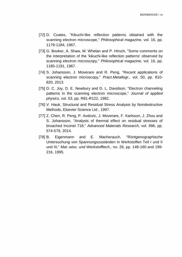
REFERENCES | 72
[72] D. Coates, "Kikuchi-like reflection patterns obtained with the
scanning electron microscope," Philosophical magazine, vol. 16, pp.
1179-1184, 1967.
[73] G. Booker, A. Shaw, M. Whelan and P. Hirsch, "Some comments on
the interpretation of the 'kikuchi-like reflection patterns' observed by
scanning electron microscopy," Philosophical magazine, vol. 16, pp.
1185-1191, 1967.
[74] S. Johansson, J. Moverare and R. Peng, "Recent applications of
scanning electron microscopy," Pract.Metallogr., vol. 50, pp. 810-
820, 2013.
[75] D. C. Joy, D. E. Newbury and D. L. Davidson, "Electron channeling
patterns in the scanning electron microscope," Journal of applied
physics, vol. 53, pp. R81-R122, 1982.
[76] V. Hauk, Structural and Residual Stress Analysis by Nondestructive
Methods, Elsevier Science Ltd , 1997.
[77] Z. Chen, R. Peng, P. Avdovic, J. Moverare, F. Karlsson, J. Zhou and
S. Johansson, "Analysis of thermal effect on residual stresses of
broached Inconel 718," Advanced Materials Research, vol. 996, pp.
574-579, 2014.
[78] B. Eigenmann and E. Macherauch, "Röntgenographische
Untersuchung von Spannungszuständen in Werkstoffen Teil I und II
und III," Mat.-wiss. und Werkstofftech., no. 26, pp. 148-160 and 199-
216, 1995.