Embed Size (px)
Citation preview
Find us at www.keysight.com Page 1
Infiniium Oscilloscope Probes and Accessories
Find us at www.keysight.com Page 2
To get the most out of your Keysight Technologies, Inc. Infiniium oscilloscope, you need the right probes
and accessories for your particular applications. Whether you need the high bandwidth and low loading
of an active probe, an easy way to connect to surface mount ICs, or a passive probe to measure high
voltages, there’s a wide selection of high-quality probes and accessories for your Infiniium oscilloscope.
Table of Contents
Probe Compatibility Table ............................................................................................................................................... 3
InfiniiMax Active Probe System Overview ...................................................................................................................... 4
InfiniiMax Ultra Series .................................................................................................................................................. 12
InfiniiMax RC Probe ..................................................................................................................................................... 14
InfiniiMax Gen III/III+ Probes ........................................................................................................................................ 19
InfiniiMax Gen II Probes ............................................................................................................................................... 28
InfiniiMax Gen I Probes ................................................................................................................................................ 33
Optical-to-Electrical Converters — N7005A 60 GHz .................................................................................................... 37
Optical-to-Electrical Converters — N7004A 33 GHz .................................................................................................... 38
Active Termination Adapter — N7010A ....................................................................................................................... 41
InfiniiMode Active Probes — N2750A/51A/52A............................................................................................................ 43
Single-Ended Active Probes — N2795A/96A/97A ....................................................................................................... 48
Power Rail Probes — N7020A 2 GHz Power Rail Probe ............................................................................................. 51
Power Rail Probes — N7024A 6 GHz Power Rail Probe ............................................................................................. 52
High-Voltage Differential Probes — DP0001A .............................................................................................................. 53
High-Voltage Differential Probes — N2790A/91A/891A ............................................................................................... 55
High-Voltage Differential Probes — N2804A/05A ........................................................................................................ 56
General Purpose Differential Probes — N2818A/19A .................................................................................................. 58
AC/DC Current Probes — 1146B ................................................................................................................................. 59
AC/DC Current Probes — 1147B/N2893A/N7026A ..................................................................................................... 60
AC/DC Current Probes — N2780B/81B/82B/83B/83L ................................................................................................. 62
Rogowski Coil AC Current Probes — N7040A/41A/42A .............................................................................................. 64
High-Sensitivity Current Probes — N2820A/21A .......................................................................................................... 65
General Purpose Passive Probes — N2870A-76A ...................................................................................................... 67
Extreme Temperature Passive Probe — N7007A ........................................................................................................ 71
High Voltage Passive Probes — 10076C ..................................................................................................................... 72
Accessories — Mixed Signal Oscilloscope Logic Probes ............................................................................................. 74
Accessories — N2744A T2A Probe Interface Adapter ................................................................................................. 77
Accessories — N2784A/85A/86A/87A Probe Positioners ............................................................................................ 79
Accessories — Wedge Probe Adapters ....................................................................................................................... 80
Accessories — Fine Pitch and PC Board Accessories ................................................................................................. 81
Related Literature ......................................................................................................................................................... 83
Find us at www.keysight.com Page 3
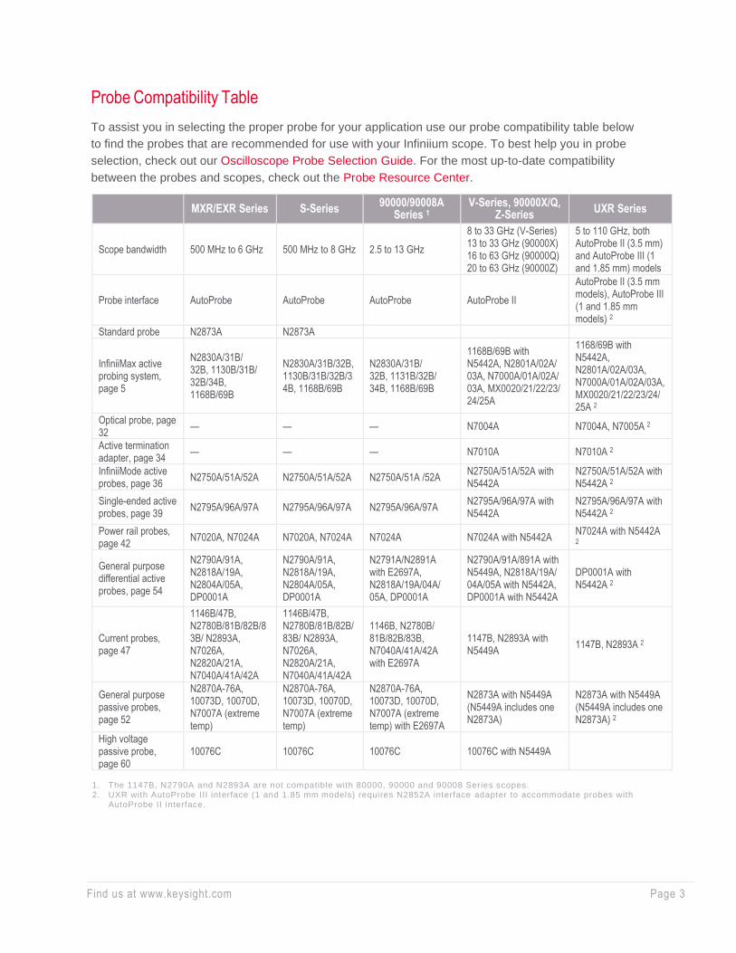
Probe Compatibility Table
To assist you in selecting the proper probe for your application use our probe compatibility table below
to find the probes that are recommended for use with your Infiniium scope. To best help you in probe
selection, check out our Oscilloscope Probe Selection Guide. For the most up-to-date compatibility
between the probes and scopes, check out the Probe Resource Center.
MXR/EXR Series S-Series 90000/90008A
Series 1 V-Series, 90000X/Q,
Z-Series UXR Series
Scope bandwidth 500 MHz to 6 GHz 500 MHz to 8 GHz 2.5 to 13 GHz
8 to 33 GHz (V-Series) 13 to 33 GHz (90000X) 16 to 63 GHz (90000Q) 20 to 63 GHz (90000Z)
5 to 110 GHz, both AutoProbe II (3.5 mm) and AutoProbe III (1 and 1.85 mm) models
Probe interface AutoProbe AutoProbe AutoProbe AutoProbe II
AutoProbe II (3.5 mm models), AutoProbe III (1 and 1.85 mm models) 2
Standard probe N2873A N2873A
InfiniiMax active probing system, page 5
N2830A/31B/ 32B, 1130B/31B/ 32B/34B, 1168B/69B
N2830A/31B/32B, 1130B/31B/32B/34B, 1168B/69B
N2830A/31B/ 32B, 1131B/32B/ 34B, 1168B/69B
1168B/69B with N5442A, N2801A/02A/ 03A, N7000A/01A/02A/ 03A, MX0020/21/22/23/ 24/25A
1168/69B with N5442A, N2801A/02A/03A, N7000A/01A/02A/03A, MX0020/21/22/23/24/ 25A 2
Optical probe, page 32
— — — N7004A N7004A, N7005A 2
Active termination adapter, page 34
— — — N7010A N7010A 2
InfiniiMode active probes, page 36
N2750A/51A/52A N2750A/51A/52A N2750A/51A /52A N2750A/51A/52A with N5442A
N2750A/51A/52A with N5442A 2
Single-ended active probes, page 39
N2795A/96A/97A N2795A/96A/97A N2795A/96A/97A N2795A/96A/97A with N5442A
N2795A/96A/97A with N5442A 2
Power rail probes, page 42
N7020A, N7024A N7020A, N7024A N7024A N7024A with N5442A N7024A with N5442A 2
General purpose differential active probes, page 54
N2790A/91A, N2818A/19A, N2804A/05A, DP0001A
N2790A/91A, N2818A/19A, N2804A/05A, DP0001A
N2791A/N2891A with E2697A, N2818A/19A/04A/ 05A, DP0001A
N2790A/91A/891A with N5449A, N2818A/19A/ 04A/05A with N5442A, DP0001A with N5442A
DP0001A with N5442A 2
Current probes, page 47
1146B/47B, N2780B/81B/82B/83B/ N2893A, N7026A, N2820A/21A, N7040A/41A/42A
1146B/47B, N2780B/81B/82B/83B/ N2893A, N7026A, N2820A/21A, N7040A/41A/42A
1146B, N2780B/ 81B/82B/83B, N7040A/41A/42A with E2697A
1147B, N2893A with N5449A
1147B, N2893A 2
General purpose passive probes, page 52
N2870A-76A, 10073D, 10070D, N7007A (extreme temp)
N2870A-76A, 10073D, 10070D, N7007A (extreme temp)
N2870A-76A, 10073D, 10070D, N7007A (extreme temp) with E2697A
N2873A with N5449A (N5449A includes one N2873A)
N2873A with N5449A (N5449A includes one N2873A) 2
High voltage passive probe, page 60
10076C 10076C 10076C 10076C with N5449A
1. The 1147B, N2790A and N2893A are not compatible with 80000, 90000 and 90008 Series scopes. 2. UXR with AutoProbe III interface (1 and 1.85 mm models) requires N2852A interface adapter to accommodate probes with
AutoProbe II interface.

Find us at www.keysight.com Page 4
InfiniiMax Active Probe System Overview
For All High-Speed Digital Design Engineers
Get the highest performance available for measuring differential and single-ended signals on high-
density ICs and PCBs. As devices get smaller and faster, accurately probing signals becomes more
challenging. Keysight’s InfiniiMax Probing System has the most accurate probe amplifiers, the widest
variety of probe heads, and all the accessories you need to get the job done.
Best Accuracy
• Highest bandwidth, up to 30 GHz probe amplifier
• Industry’s lowest probe loading and noise gives you a more accurate representation of your
signals
• S-parameter corrections for a more accurate probe response
• Flat frequency response over the entire bandwidth eliminates distortion and ensures accurate
measurement
Easy-to-Use
• The widest variety of probe heads and accessories available on the market
• InfiniiMode technology enables you to measure differential, single-ended A or B, and
common-mode without having to reconnect the probe
• Easily probe small devices with the super flexible micro probe head
• QuickTip heads for a quick and secure connection
Industry-Leading
• Extreme temperature probing solutions from -55 to +150 °C - enables measurements in environmental
chambers
• Damping resistor tips prevent signal distortion at high frequency
• Replaceable browser tips give you improved usability and versatility
• Economical solder-in differential probing solution with Zero Insertion Force (ZIF) probe heads
Find us at www.keysight.com Page 5
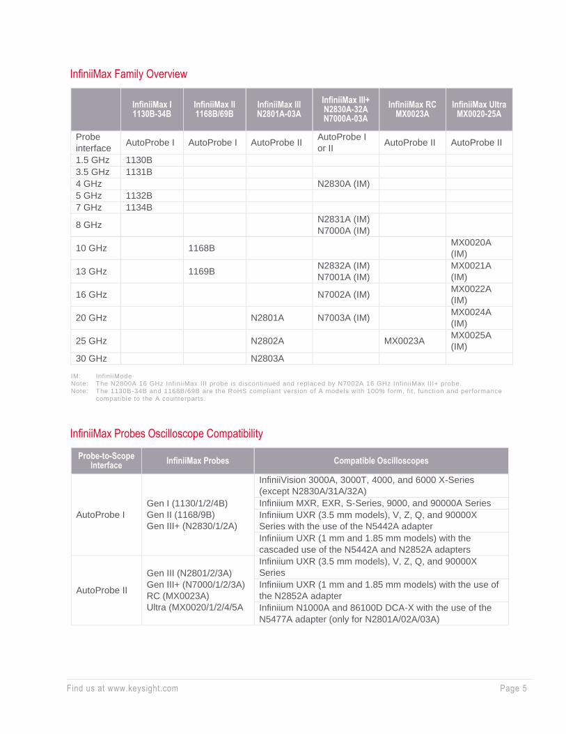
InfiniiMax Family Overview
InfiniiMax I 1130B-34B
InfiniiMax II 1168B/69B
InfiniiMax III N2801A-03A
InfiniiMax III+ N2830A-32A N7000A-03A
InfiniiMax RC MX0023A
InfiniiMax Ultra MX0020-25A
Probe
interface AutoProbe I AutoProbe I AutoProbe II
AutoProbe I
or II AutoProbe II AutoProbe II
1.5 GHz 1130B
3.5 GHz 1131B
4 GHz N2830A (IM)
5 GHz 1132B
7 GHz 1134B
8 GHz N2831A (IM)
N7000A (IM)
10 GHz 1168B MX0020A
(IM)
13 GHz 1169B N2832A (IM)
N7001A (IM)
MX0021A
(IM)
16 GHz N7002A (IM) MX0022A
(IM)
20 GHz N2801A N7003A (IM) MX0024A
(IM)
25 GHz N2802A MX0023A MX0025A
(IM)
30 GHz N2803A
IM: InfiniiMode Note: The N2800A 16 GHz InfiniiMax III probe is discontinued and replaced by N7002A 16 GHz InfiniiMax III+ probe. Note: The 1130B-34B and 1168B/69B are the RoHS compliant version of A models with 100% form, f it, function and performance
compatible to the A counterparts.
InfiniiMax Probes Oscilloscope Compatibility
Probe-to-Scope Interface
InfiniiMax Probes Compatible Oscilloscopes
AutoProbe I
Gen I (1130/1/2/4B)
Gen II (1168/9B)
Gen III+ (N2830/1/2A)
InfiniiVision 3000A, 3000T, 4000, and 6000 X-Series
(except N2830A/31A/32A)
Infiniium MXR, EXR, S-Series, 9000, and 90000A Series
Infiniium UXR (3.5 mm models), V, Z, Q, and 90000X
Series with the use of the N5442A adapter
Infiniium UXR (1 mm and 1.85 mm models) with the
cascaded use of the N5442A and N2852A adapters
AutoProbe II
Gen III (N2801/2/3A)
Gen III+ (N7000/1/2/3A)
RC (MX0023A)
Ultra (MX0020/1/2/4/5A
Infiniium UXR (3.5 mm models), V, Z, Q, and 90000X
Series
Infiniium UXR (1 mm and 1.85 mm models) with the use of
the N2852A adapter
Infiniium N1000A and 86100D DCA-X with the use of the
N5477A adapter (only for N2801A/02A/03A)
Find us at www.keysight.com Page 6
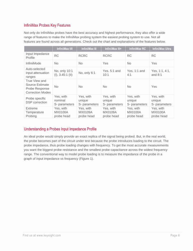
InfiniiMax Probes Key Features
Not only do InfiniiMax probes have the best accuracy and highest performance, they also offer a wide
range of features to make the InfiniiMax probing system the easiest probing system to use. Not all
features are found across all generations. Check out the chart and explanations of the features below.
InfiniiMax I/II InfiniiMax III InfiniiMax III+ InfiniiMax RC InfiniiMax Ultra
Input Impedance
Profile RC RCRC RCRC RC RC
InfiniiMode No No Yes No Yes
Auto-selected
input attenuation
ranges
No, only 10:1
(I), 3.45:1 (II) No, only 6:1
Yes, 5:1 and
10:1
Yes, 1:1 and
4:1
Yes, 1:1, 4:1,
and 8:1
True View and
Source Estimate
Probe Response
Correction Modes
No No No No Yes
Probe specific
DSP correction
Yes, with
nominal
S- parameters
Yes, with
unique
S- parameters
Yes, with
unique
S- parameters
Yes, with
unique
S- parameters
Yes, with
unique
S- parameters
Extreme
Temperature
Probing
Yes, with
MX0100A
probe head
Yes, with
MX0109A
probe head
Yes, with
MX0109A
probe head
Yes, with
MX0100A
probe head
Yes, with
MX0100A
probe head
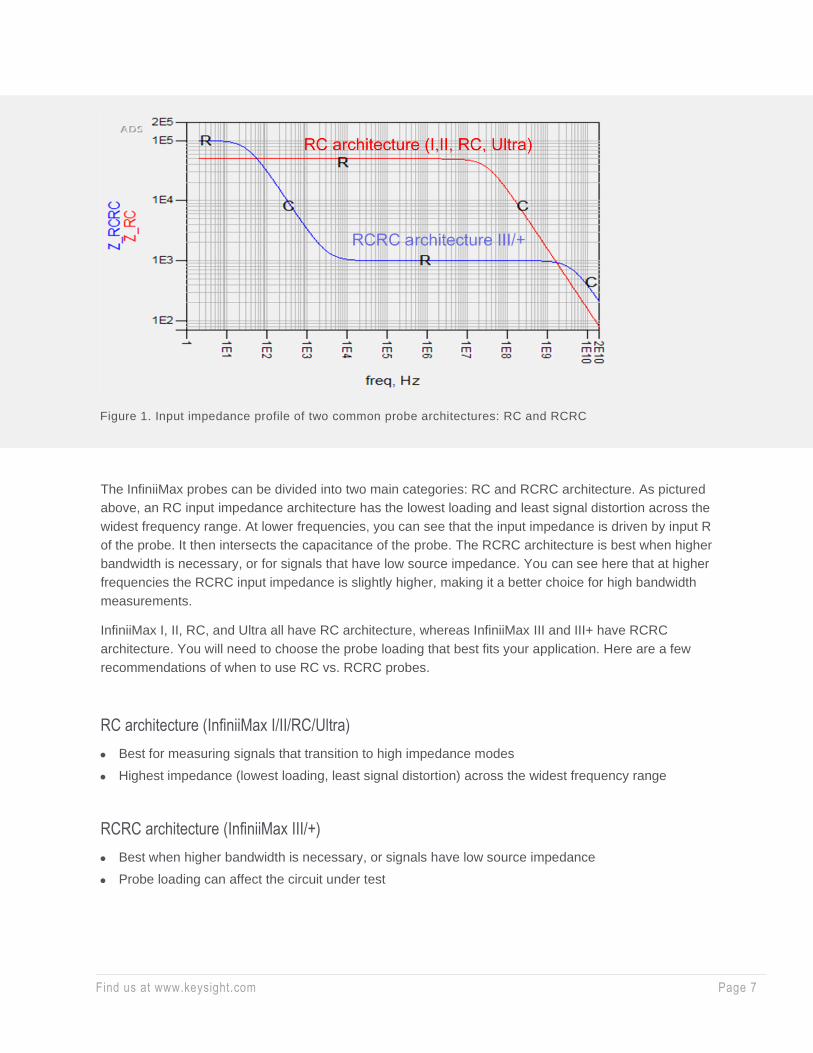
Understanding a Probes Input Impedance Profile
An ideal probe would simply provide an exact replica of the signal being probed. But, in the real world,
the probe becomes part of the circuit under test because the probe introduces loading to the circuit. The
probe impedance, thus probe loading changes with frequency. To get the most accurate measurements
you want the biggest probe resistance and the smallest probe capacitance across the widest frequency
range. The conventional way to model probe loading is to measure the impedance of the probe in a
graph of input impedance vs frequency (Figure 1).
Find us at www.keysight.com Page 7
The InfiniiMax probes can be divided into two main categories: RC and RCRC architecture. As pictured
above, an RC input impedance architecture has the lowest loading and least signal distortion across the
widest frequency range. At lower frequencies, you can see that the input impedance is driven by input R
of the probe. It then intersects the capacitance of the probe. The RCRC architecture is best when higher
bandwidth is necessary, or for signals that have low source impedance. You can see here that at higher
frequencies the RCRC input impedance is slightly higher, making it a better choice for high bandwidth
measurements.
InfiniiMax I, II, RC, and Ultra all have RC architecture, whereas InfiniiMax III and III+ have RCRC
architecture. You will need to choose the probe loading that best fits your application. Here are a few
recommendations of when to use RC vs. RCRC probes.
RC architecture (InfiniiMax I/II/RC/Ultra)
• Best for measuring signals that transition to high impedance modes
• Highest impedance (lowest loading, least signal distortion) across the widest frequency range
RCRC architecture (InfiniiMax III/+)
• Best when higher bandwidth is necessary, or signals have low source impedance
• Probe loading can affect the circuit under test
Figure 1. Input impedance profile of two common probe architectures: RC and RCRC

Find us at www.keysight.com Page 8
InfiniiMode
In many of today’s high-speed serial bus standards, the accurate measurement of single-ended and
common-mode components of a differential signal is often compromised by having to rely on multiple
probe channels and a scope’s internal math functions, but these methods are prone to errors and
cumbersome to use. InfiniiMode allows you to measure differential, single-ended and common-mode
characteristics of a differential signal with a signal connection. You will need to connect four inputs
consisting of two differential signal inputs: +lead, -lead and two ground connections to make the multi-
mode measurements possible with a single connection. Once you connect all input leads to the target,
you don’t need to reconnect the probe and it just takes one channel on the scope to make all three
measurements. To make InfiniiMode measurements, you need both a probe amplifier and probe heads
that are InfiniiMode capable.
Auto-Selected Input Attenuation Ranges
More attenuation ranges give you superior noise performance and larger voltage ranges all while
maintaining maximum bandwidth. With auto-selected input attenuation ranges, the input range is
automatically configured depending on the size of the input signal and the vertical scale of the scope.
True View and Source Estimate Probe Response Correction Modes
You can choose whether you want your probe to show you the voltage at the tip of probe (Vout/Vin -
True View) as loaded by the probe or the estimate of the voltage at the probe point before the probe
load was applied (Vout/Vsource - Source Estimate).
Some helpful definitions:
• Vsource - The signal at the probe point “before” the probe is connected which would be the signal at
the probe point if an ideal probe with infinite input impedance were connected.
• Vin - The signal at the probe point while the signal is being loaded by the probe. Probe loading is
caused by the input impedance of the probe making a voltage divider with the source impedance of
the circuit being measured.
• Vout - The signal that is output from the probe or the signal that is shown on the scope screen.
• Source impedance - The impedance of the circuit that is driving the probe, which is the impedance
looking back to the point being probed with the probe connected.

Find us at www.keysight.com Page 9
Probe Specific DSP Correction
When an InfiniiMax probe is connected to a scope channel and the proper probe head is selected, the
scope calculates a DSP correction filter that includes the probe head, probe amplifier, and scope
channel. This provides the maximum measurement accuracy for the complete probe and scope channel
system. Some InfiniiMax probes store unique S parameters in on board memory for the scope to read
out when the probe amp is connected to the scope. Unique S-parameters, as opposed to nominal,
means each individual probe amp contains its own frequency response data to further flatten the
magnitude and phase response of the probe for high accuracy measurements. Nominal S-parameters
mean that s-parameters are standard across all probe models but are still used in the DSP correction
algorithms.
Extreme Temperature Probing
InfiniiMax probes offer wide operating temperatures ranges with the appropriate probe head, making
them ideal for environmental chamber testing with the probe head soldered to the DUT inside the
chamber. The MX0100A 25 GHz micro probe head and the MX0109A 26 GHz solder-in probe head are
both rated for a range of -55 to +150 °C as per JEDEC JESD22-A104 revision E spec.
InfiniiMax Probe Heads and Accessories
Keysight’s InfiniiMax probing system supports a wide variety of high-speed probing applications with an
extensive line-up of probe heads and accessories. Most InfiniiMax probe heads and accessories are
split up into 2 groups based on input impedance architecture: RC architecture (Gen I, II, RC, and Ultra)
and RCRC architecture (Gen III and III+). RC probe heads are only compatible with RC probe
amplifiers; likewise, RCRC probe heads are only compatible with RCRC probe amplifiers.
True View Source Estimate
Pros
The signal at the output of the probe is an
accurate representation of the signal that
currently exists, as it is being probed.
Best to use for receiver sensitivity because
you have to measure what is actually there.
Doesn’t hide the fact that the probe loaded
the signal.
When system source impedance is known, it
more accurately depicts the signal before it
was probed.
Best to use for transmitter test because it is
best at estimating the signal coming out of the
transmitter.
Cons
Doesn’t estimate signal that was there before
being probed.
Signal at the probe point is loaded at the
probe.
Error in receiver type testing because doesn’t
show the signal that is actually there while
being probed
Hides the effect that probe loading has on the
signal being probed.
Find us at www.keysight.com Page 10
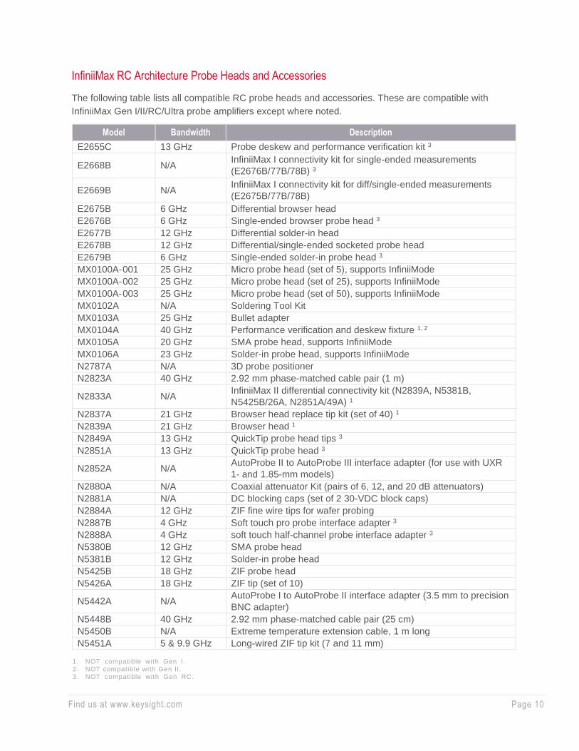
InfiniiMax RC Architecture Probe Heads and Accessories
The following table lists all compatible RC probe heads and accessories. These are compatible with
InfiniiMax Gen I/II/RC/Ultra probe amplifiers except where noted.
Model Bandwidth Description
E2655C 13 GHz Probe deskew and performance verification kit 3
E2668B N/A InfiniiMax I connectivity kit for single-ended measurements
(E2676B/77B/78B) 3
E2669B N/A InfiniiMax I connectivity kit for diff/single-ended measurements
(E2675B/77B/78B)
E2675B 6 GHz Differential browser head
E2676B 6 GHz Single-ended browser probe head 3
E2677B 12 GHz Differential solder-in head
E2678B 12 GHz Differential/single-ended socketed probe head
E2679B 6 GHz Single-ended solder-in probe head 3
MX0100A- 001 25 GHz Micro probe head (set of 5), supports InfiniiMode
MX0100A- 002 25 GHz Micro probe head (set of 25), supports InfiniiMode
MX0100A- 003 25 GHz Micro probe head (set of 50), supports InfiniiMode
MX0102A N/A Soldering Tool Kit
MX0103A 25 GHz Bullet adapter
MX0104A 40 GHz Performance verification and deskew fixture 1, 2
MX0105A 20 GHz SMA probe head, supports InfiniiMode
MX0106A 23 GHz Solder-in probe head, supports InfiniiMode
N2787A N/A 3D probe positioner
N2823A 40 GHz 2.92 mm phase-matched cable pair (1 m)
N2833A N/A InfiniiMax II differential connectivity kit (N2839A, N5381B,
N5425B/26A, N2851A/49A) 1
N2837A 21 GHz Browser head replace tip kit (set of 40) 1
N2839A 21 GHz Browser head 1
N2849A 13 GHz QuickTip probe head tips 3
N2851A 13 GHz QuickTip probe head 3
N2852A N/A AutoProbe II to AutoProbe III interface adapter (for use with UXR
1- and 1.85-mm models)
N2880A N/A Coaxial attenuator Kit (pairs of 6, 12, and 20 dB attenuators)
N2881A N/A DC blocking caps (set of 2 30-VDC block caps)
N2884A 12 GHz ZIF fine wire tips for wafer probing
N2887B 4 GHz Soft touch pro probe interface adapter 3
N2888A 4 GHz soft touch half-channel probe interface adapter 3
N5380B 12 GHz SMA probe head
N5381B 12 GHz Solder-in probe head
N5425B 18 GHz ZIF probe head
N5426A 18 GHz ZIF tip (set of 10)
N5442A N/A AutoProbe I to AutoProbe II interface adapter (3.5 mm to precision
BNC adapter)
N5448B 40 GHz 2.92 mm phase-matched cable pair (25 cm)
N5450B N/A Extreme temperature extension cable, 1 m long
N5451A 5 & 9.9 GHz Long-wired ZIF tip kit (7 and 11 mm)
1. NOT compatible with Gen I. 2. NOT compatible with Gen II. 3. NOT compatible with Gen RC.
Find us at www.keysight.com Page 11
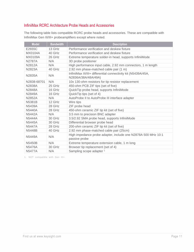
InfiniiMax RCRC Architecture Probe Heads and Accessories
The following table lists compatible RCRC probe heads and accessories. These are compatible with
InfiniiMax Gen III/III+ probe amplifiers except where noted.
Model Bandwidth Description
E2655C 13 GHz Performance verification and deskew fixture
MX0104A 40 GHz Performance verification and deskew fixture
MX0109A 26 GHz Extreme temperature solder-in head, supports InfiniiMode
N2787A N/A 3D probe positioner
N2812A N/A High performance input cable, 2.92 mm connectors, 1 m length
N2823A 40 GHz 2.92 mm phase-matched cable pair (1 m)
N2835A N/A InfiniiMax III/III+ differential connectivity kit (N5439A/45A,
N2836A/38A/48A/49A)
N2838-68701 N/A 10x 130-ohm resistors for tip resistor replacement
N2838A 25 GHz 450-ohm PCB ZIF tips (set of five)
N2848A 16 GHz QuickTip probe head, supports InfiniiMode
N2849A 16 GHz QuickTip tips (set of 4)
N2852A N/A AutoProbe II to AutoProbe III interface adapter
N5381B 12 GHz Wire tips
N5439A 28 GHz ZIF probe head
N5440A 28 GHz 450-ohm ceramic ZIF tip kit (set of five)
N5442A N/A 3.5 mm to precision BNC adapter
N5444A 30 GHz 3.5/2.92 SMA probe head, supports InfiniiMode
N5445A 30 GHz Differential browser probe head
N5447A 28 GHz 200-ohm ceramic ZIF tip kit (set of five)
N5448B 40 GHz 2.92 mm phase-matched cable pair (25cm)
N5449A N/A High impedance probe adapter, include one N2878A 500 MHz 10:1
passive probe
N5450B N/A Extreme temperature extension cable, 1 m long
N5476A 30 GHz Browser tip replacement (set of 4)
N5477A N/A Sampling scope adapter 1
1. NOT compatible with Gen III+.

Find us at www.keysight.com Page 12
InfiniiMax Ultra Series
The latest series of InfiniiMax probes for high speed digital designers. They are the most accurate and
easiest to use.
Ultra Performance
• Lowest noise to see your signal more clearly
• More breadth with 5 models ranging from 10 to 25 GHz of bandwidth
• Highest input impedance in midband frequencies, crucial for probing high impedance modes
Ultra Accuracy
• Highest accuracy across the widest frequency range to see the truest representation of your signal
• Lowest loading for least impact to your circuit
• Boost test margins with the least signal distortion from your probe
Ultra Usability
• Easily probe small devices with the super flexible micro probe head
• Compatible with your existing probe heads and accessories
• Measure differential, single-ended, and common mode signals with a single probe tip
Model Bandwidth Description
MX0020A 10 GHz InfiniiMax Ultra probe amplifier, AutoProbe 2 interface
MX0021A 13 GHz InfiniiMax Ultra probe amplifier, AutoProbe 2 interface
MX0022A 16 GHz InfiniiMax Ultra probe amplifier, AutoProbe 2 interface
MX0024A 20 GHz InfiniiMax Ultra probe amplifier, AutoProbe 2 interface
MX0025A 25 GHz InfiniiMax Ultra probe amplifier, AutoProbe 2 interface
Find us at www.keysight.com Page 13
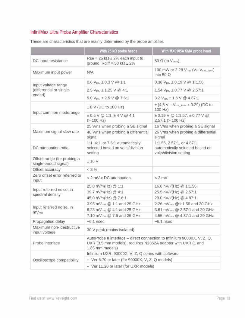
InfiniiMax Ultra Probe Amplifier Characteristics
These are characteristics that are mainly determined by the probe amplifier.
With 25 kΩ probe heads With MX0105A SMA probe head
DC input resistance Rse = 25 kΩ ± 2% each input to
ground, Rdiff = 50 kΩ ± 2% 50 Ω (to Vterm)
Maximum input power N/A 100 mW or 2.28 Vrms (Vin-Vcm_term)
into 50 Ω
Input voltage range
(differential or single-
ended)
0.6 Vpp, ± 0.3 V @ 1:1 0.38 Vpp, ± 0.19 V @ 1:1.56
2.5 Vpp, ± 1.25 V @ 4:1 1.54 Vpp, ± 0.77 V @ 2.57:1
5.0 Vpp, ± 2.5 V @ 7.6:1 3.2 Vpp, ± 1.6 V @ 4.87:1
Input common mode range
± 8 V (DC to 100 Hz) ± (4.3 V – Vcm_term x 0.29) (DC to
100 Hz)
± 0.5 V @ 1:1, ± 4 V @ 4:1
(> 100 Hz)
± 0.19 V @ 1:1.57, ± 0.77 V @
2.57:1 (> 100 Hz)
Maximum signal slew rate
25 V/ns when probing a SE signal 16 V/ns when probing a SE signal
40 V/ns when probing a differential
signal
26 V/ns when probing a differential
signal
DC attenuation ratio
1:1, 4:1, or 7.6:1 automatically
selected based on volts/division
setting
1:1.56, 2.57:1, or 4.87:1
automatically selected based on
volts/division setting
Offset range (for probing a
single-ended signal) ± 16 V
Offset accuracy < 3 %
Zero offset error referred to
input < 2 mV x DC attenuation < 2 mV
Input referred noise, in
spectral density
25.0 nV/√(Hz) @ 1:1 16.0 nV/√(Hz) @ 1:1.56
39.7 nV/√(Hz) @ 4:1 25.5 nV/√(Hz) @ 2.57:1
45.0 nV/√(Hz) @ 7.6:1 29.0 nV/√(Hz) @ 4.87:1
Input referred noise, in
mVrms
3.95 mVrms @ 1:1 and 25 GHz 2.26 mVrms @1:1.56 and 20 GHz
6.28 mVrms @ 4:1 and 25 GHz 3.61 mVrms @ 2.57:1 and 20 GHz
7.10 mVrms @ 7.6 and 25 GHz 4.55 mVrms @ 4.87:1 and 20 GHz
Propagation delay ~6.1 nsec ~6.1 nsec
Maximum non- destructive
input voltage 30 V peak (mains isolated)
Probe interface
AutoProbe II interface – direct connection to Infiniium 90000X, V, Z, Q,
UXR (3.5 mm models), requires N2852A adapter with UXR (1 and
1.85 mm models)
Oscilloscope compatibility
Infiniium UXR, 90000X, V, Z, Q series with software
• Ver 6.70 or later (for 90000X, V, Z, Q models)
• Ver 11.20 or later (for UXR models)
Find us at www.keysight.com Page 14
For more information on the InfiniiMax Ultra Series, please see the
following datasheet and user guide.
• InfiniiMax Ultra User Guide
• InfiniiMax Ultra Data Sheet
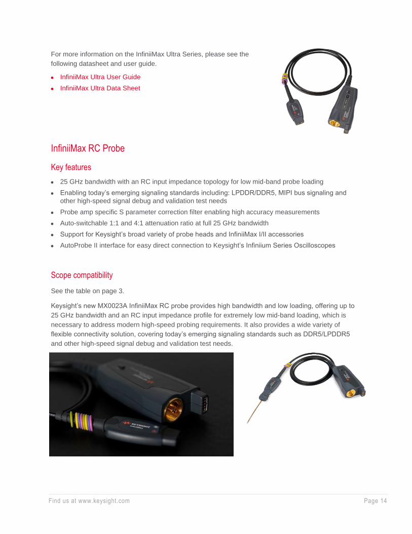
InfiniiMax RC Probe
Key features
• 25 GHz bandwidth with an RC input impedance topology for low mid-band probe loading
• Enabling today’s emerging signaling standards including: LPDDR/DDR5, MIPI bus signaling and
other high-speed signal debug and validation test needs
• Probe amp specific S parameter correction filter enabling high accuracy measurements
• Auto-switchable 1:1 and 4:1 attenuation ratio at full 25 GHz bandwidth
• Support for Keysight’s broad variety of probe heads and InfiniiMax I/II accessories
• AutoProbe II interface for easy direct connection to Keysight’s Infiniium Series Oscilloscopes
Scope compatibility
See the table on page 3.
Keysight’s new MX0023A InfiniiMax RC probe provides high bandwidth and low loading, offering up to
25 GHz bandwidth and an RC input impedance profile for extremely low mid-band loading, which is
necessary to address modern high-speed probing requirements. It also provides a wide variety of
flexible connectivity solution, covering today’s emerging signaling standards such as DDR5/LPDDR5
and other high-speed signal debug and validation test needs.

Find us at www.keysight.com Page 15
Characteristics performance plots: MX0023A 25 GHz probe amp with MX0100A micro probe head
Frequency response of an ideal 25 GHz brickwall filter (red) and the typical DSP corrected probe
response filtered by the brickwall filter (blue).
Time domain step responses for the two responses
CMRR for the 1:1 (red) and 4:1 (blue) mode.
Find us at www.keysight.com Page 16
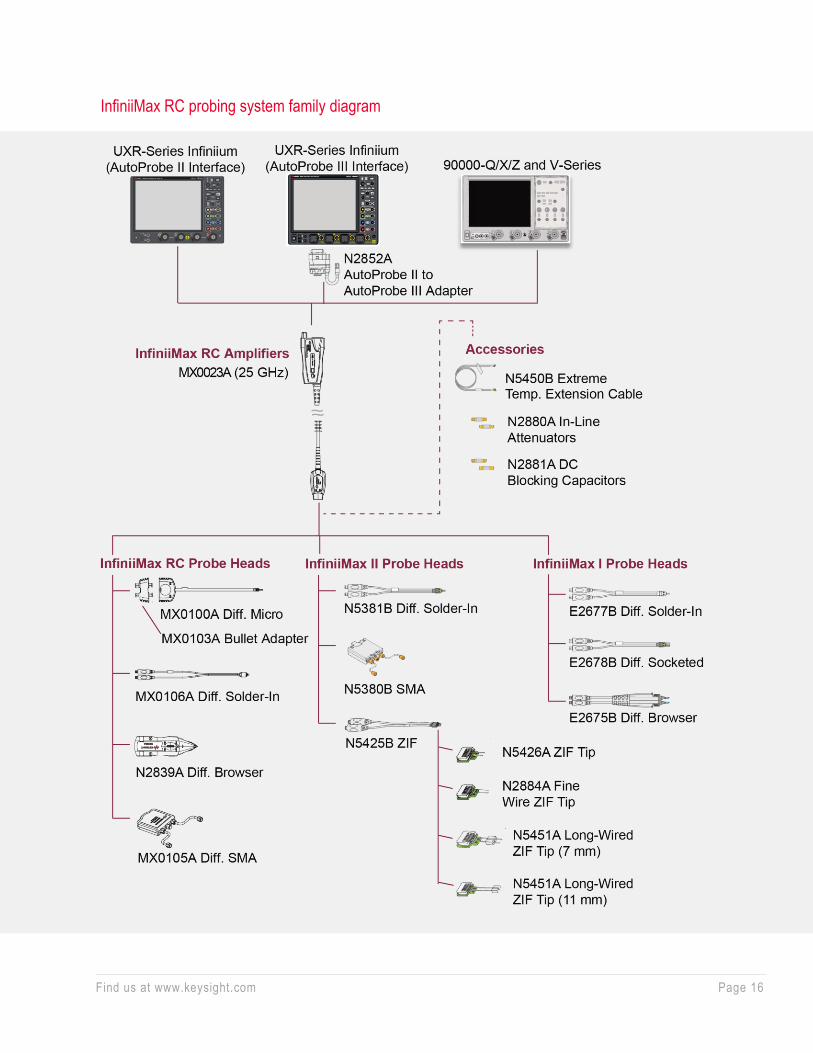
InfiniiMax RC probing system family diagram
Find us at www.keysight.com Page 17
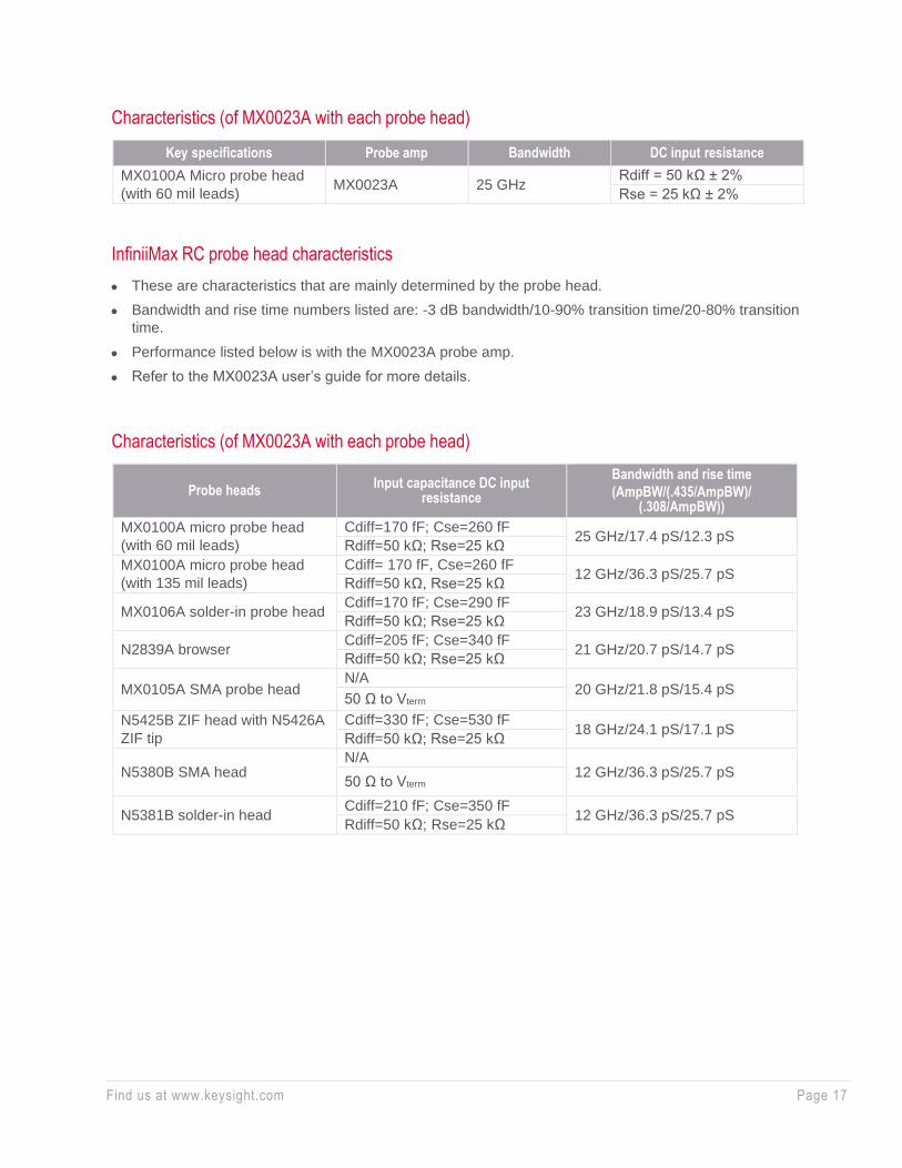
Characteristics (of MX0023A with each probe head)
Key specifications Probe amp Bandwidth DC input resistance
MX0100A Micro probe head
(with 60 mil leads) MX0023A 25 GHz
Rdiff = 50 kΩ ± 2%
Rse = 25 kΩ ± 2%
InfiniiMax RC probe head characteristics
• These are characteristics that are mainly determined by the probe head.
• Bandwidth and rise time numbers listed are: -3 dB bandwidth/10-90% transition time/20-80% transition
time.
• Performance listed below is with the MX0023A probe amp.
• Refer to the MX0023A user’s guide for more details.
Characteristics (of MX0023A with each probe head)
Probe heads Input capacitance DC input
resistance
Bandwidth and rise time
(AmpBW/(.435/AmpBW)/ (.308/AmpBW))
MX0100A micro probe head
(with 60 mil leads)
Cdiff=170 fF; Cse=260 fF 25 GHz/17.4 pS/12.3 pS
Rdiff=50 kΩ; Rse=25 kΩ
MX0100A micro probe head
(with 135 mil leads)
Cdiff= 170 fF, Cse=260 fF 12 GHz/36.3 pS/25.7 pS
Rdiff=50 kΩ, Rse=25 kΩ
MX0106A solder-in probe head Cdiff=170 fF; Cse=290 fF
23 GHz/18.9 pS/13.4 pS Rdiff=50 kΩ; Rse=25 kΩ
N2839A browser Cdiff=205 fF; Cse=340 fF
21 GHz/20.7 pS/14.7 pS Rdiff=50 kΩ; Rse=25 kΩ
MX0105A SMA probe head N/A
20 GHz/21.8 pS/15.4 pS 50 Ω to Vterm
N5425B ZIF head with N5426A
ZIF tip
Cdiff=330 fF; Cse=530 fF 18 GHz/24.1 pS/17.1 pS
Rdiff=50 kΩ; Rse=25 kΩ
N5380B SMA head N/A
12 GHz/36.3 pS/25.7 pS 50 Ω to Vterm
N5381B solder-in head Cdiff=210 fF; Cse=350 fF
12 GHz/36.3 pS/25.7 pS Rdiff=50 kΩ; Rse=25 kΩ

Find us at www.keysight.com Page 18
InfiniiMax RC probe amp characteristics
These are characteristics that are mainly determined by the probe amp.
With 25 kΩ probe heads With MX0105A SMA probe head
DC input resistance Rse = 25 kΩ ± 2% each input to
ground, Rdiff = 50 kΩ ± 2% 50 Ω (to Vterm)
Maximum input power N/A 100 mW or 2.28 Vrms (Vin-
Vcm_term) into 50 Ω
Input voltage range
(differential or single-ended)
0.6 Vpp, ± 0.3 V (at 1:1) 0.38 Vpp, ± 0.19 V (at 1:1.56)
2.5 Vpp, ± 1.25 V (at 4:1) 1.54 Vpp, ± 0.77 V (at 2.57:1)
Input common mode range
± 8 V (DC to 100 Hz) ± (4.3 V – Vcm_term x 0.29) (DC
to 100 Hz)
± 0.5 V at 1:1, ± 4 V at 4:1
(> 100 Hz)
± 0.19 V at 1:1.57, ± 0.77 V at
2.57:1 (> 100 Hz)
Maximum signal slew rate
25 V/ns when probing a SE signal 16 V/ns when probing a SE signal
40 V/ns when probing a differential
signal
26 V/ns when probing a differential
signal
DC attenuation ratio 1:1 or 4:1, automatically selected
based on volts/division setting
1:1.56 or 2.57:1 automatically
selected based on volts/division
setting
Offset range (for probing a
single-ended signal) ± 16 V
Offset accuracy < 3 %
Zero offset error referred to
input < 2 mV x DC attenuation < 2 mV
Input referred noise, in
spectral density
25.0 nV/√(Hz) at 1:1 16 nV/√(Hz) at 1:1.56
39.7 nV/√(Hz) at 4:1 25.5 nV/√(Hz) at 2.57:1
Input referred noise, in
mVrms
3.95 mVrms at 1:1 and 25 GHz 2.26 mVrms at 1:1.56 and 20 GHz
6.28 mVrms at 4:1 and 25 GHz 3.61 mVrms at 2.57:1 and 20 GHz
Propagation delay ~6.1 nsec ~6.1 nsec
Maximum non-destructive
input voltage 30 V peak (mains isolated)
Probe interface AutoProbe II interface – direct connection to Infiniium 90000X, V, Z, Q,
UXR ≤ 33 GHz models, requires N2852A with UXR ≥ 40 GHz models
Oscilloscope compatibility
Infiniium UXR, 90000X, V, Z, Q series with software
• Ver 6.55 or later (for 90000X, V, Z, Q models)
• Ver 10.25 or later (for UXR models)

Find us at www.keysight.com Page 19
InfiniiMax Gen III/III+ Probes
Key features
• Full 30 GHz bandwidth to the probe tip
• InfiniiMode probing for making differential, single-ended and common
mode measurements with a single probe (InfiniiMax III+)
• Industry’s highest fidelity and accuracy due to bandwidth and extremely
low loading
• Probe amplifiers loaded with measured S-parameters for more accurate
response correction
• Bandwidth upgradeable (InfiniiMax III only)
• Variety of probe heads for different use models with maximum usability
Scope compatibility
See the table on page 3.
The InfiniiMax III/III+ probing system provides the highest performance and
low loading to allow for a completely new level of signal fidelity and accuracy.
Eleven different InfiniiMax III/III+ probe amplifiers ranging from 4 to 30 GHz
are available for matching your probing solution to your performance and
budget requirements. The InfiniiMax III+ probing system is the next
generation of InfiniiMax probing. It greatly expands the measurement
capability and usability of probes capable of measuring all components of a
differential signal with the built-in InfiniiMode technology.
InfiniiMax III amp with ZIF head/tips
InfiniiMax III amp with ZIF head/tips
N2830A InfiniiMax III+ amp with
QuickTip head
InfiniiMax III amp with ZIF head/tips
QuickTip head and tip
Find us at www.keysight.com Page 20
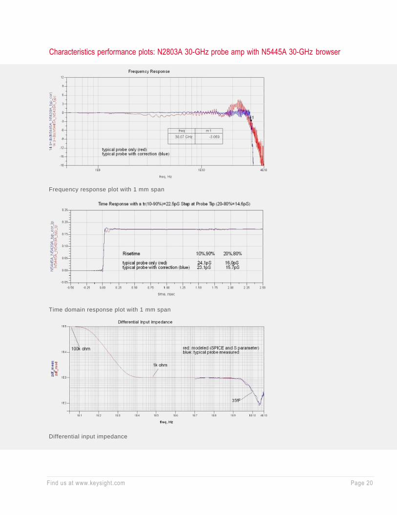
Characteristics performance plots: N2803A 30-GHz probe amp with N5445A 30-GHz browser
Frequency response plot with 1 mm span
Time domain response plot with 1 mm span
Differential input impedance
Find us at www.keysight.com Page 21
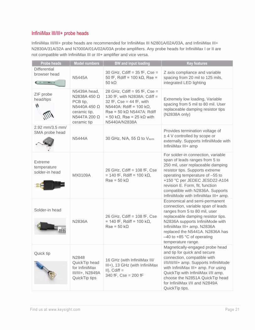
InfiniiMax III/III+ probe heads
InfiniiMax III/III+ probe heads are recommended for InfiniiMax III N2801A/02A/03A, and InfiniiMax III+
N2830A/31A/32A and N7000A/01A/02A/03A probe amplifiers. Any probe heads for InfiniiMax I or II are
not compatible with InfiniiMax III or III+ amplifier and vice versa.
Probe heads Model numbers BW and input loading Key features
Differential
browser head
N5445A
30 GHz, Cdiff = 35 fF, Cse =
50 fF, Rdiff = 100 kΩ, Rse =
50 kΩ
Z axis compliance and variable
spacing from 20 mil to 125 mils,
integrated LED lighting
ZIF probe
head/tips
N5439A head,
N2838A 450 Ω
PCB tip,
N5440A 450 Ω
ceramic tip,
N5447A 200 Ω
ceramic tip
28 GHz, Cdiff = 95 fF, Cse =
130 fF, with N2838A: Cdiff =
32 fF, Cse = 44 fF, with
N5440A: Rdiff = 100 kΩ,
Rse = 50 kΩ N5447A: Rdiff
= 50 kΩ, Rse = 25 kΩ with
N5440A/N2838A
Extremely low loading, Variable
spacing from 5 mil to 80 mil. User
replaceable damping resistor tips
(N2838A only)
2.92 mm/3.5 mm/
SMA probe head
N5444A 30 GHz, N/A, 55 Ω to Vterm
Provides termination voltage of
± 4 V controlled by scope or
externally. Supports InfiniiMode with
InfiniiMax III+ amp
Extreme
temperature
solder-in head
MX0109A
26 GHz, Cdiff = 108 fF, Cse
= 140 fF, Rdiff = 100 kΩ,
Rse = 50 kΩ
For solder-in connection, variable
span of leads ranges from 5 to
250 mil, user replaceable damping
resistor tips. Supports extreme
operating temperature of –55 to
+150 °C per JEDEC JESD22-A104
revision E. Form, fit, function
compatible with N2836A. Supports
InfiniiMode with InfiniiMax III+ amp.
Solder-in head
N2836A
26 GHz, Cdiff = 108 fF, Cse
= 140 fF, Rdiff = 100 kΩ,
Rse = 50 kΩ
Economical and semi-permanent
connection, variable span of leads
ranges from 5 to 80 mil, user
replaceable damping resistor tips.
N2836A supports InfiniiMode with
InfiniiMax III+ amp. N2836A
replaced the N5441A. N2836A has
–40 to +85 °C of operating
temperature range.
Quick tip
N2848
QuickTip head
for InfiniiMax
III/III+, N2849A
QuickTip tips
16 GHz (with InfiniiMax III/
III+), 13 GHz (with InfiniiMax
II), Cdiff =
340 fF, Cse = 200 fF
Magnetically-engaged probe head
and tip for quick and secure
connection, compatible with
I/II/III/III+ amp. Supports InfiniiMode
with InfiniiMax III+ amp. For using
QuickTip with InfiniiMax I/II amp,
choose the N2851A QuickTip head
for InfiniiMax I/II and N2849A
QuickTip tips.

Find us at www.keysight.com Page 22
InfiniiMax III/III+ probing system family diagram
Find us at www.keysight.com Page 23
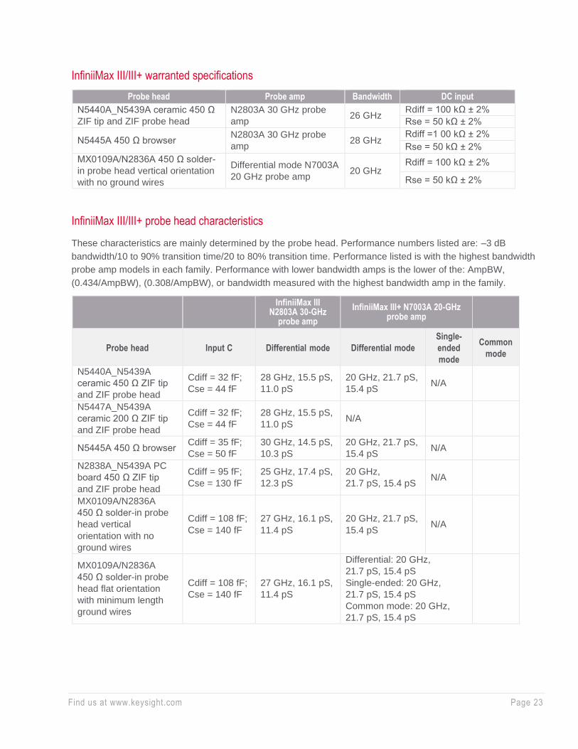
InfiniiMax III/III+ warranted specifications
Probe head Probe amp Bandwidth DC input
N5440A_N5439A ceramic 450 Ω
ZIF tip and ZIF probe head
N2803A 30 GHz probe
amp 26 GHz
Rdiff = 100 kΩ ± 2%
Rse = 50 kΩ ± 2%
N5445A 450 Ω browser N2803A 30 GHz probe
amp 28 GHz
Rdiff =1 00 kΩ ± 2%
Rse = 50 kΩ ± 2%
MX0109A/N2836A 450 Ω solder-
in probe head vertical orientation
with no ground wires
Differential mode N7003A
20 GHz probe amp 20 GHz
Rdiff = 100 kΩ ± 2%
Rse = 50 kΩ ± 2%
InfiniiMax III/III+ probe head characteristics
These characteristics are mainly determined by the probe head. Performance numbers listed are: –3 dB
bandwidth/10 to 90% transition time/20 to 80% transition time. Performance listed is with the highest bandwidth
probe amp models in each family. Performance with lower bandwidth amps is the lower of the: AmpBW,
(0.434/AmpBW), (0.308/AmpBW), or bandwidth measured with the highest bandwidth amp in the family.
InfiniiMax III
N2803A 30-GHz probe amp
InfiniiMax III+ N7003A 20-GHz probe amp
Probe head Input C Differential mode Differential mode
Single-
ended
mode
Common
mode
N5440A_N5439A
ceramic 450 Ω ZIF tip
and ZIF probe head
Cdiff = 32 fF;
Cse = 44 fF
28 GHz, 15.5 pS,
11.0 pS
20 GHz, 21.7 pS,
15.4 pS N/A
N5447A_N5439A
ceramic 200 Ω ZIF tip
and ZIF probe head
Cdiff = 32 fF;
Cse = 44 fF
28 GHz, 15.5 pS,
11.0 pS N/A
N5445A 450 Ω browser Cdiff = 35 fF;
Cse = 50 fF
30 GHz, 14.5 pS,
10.3 pS
20 GHz, 21.7 pS,
15.4 pS N/A
N2838A_N5439A PC
board 450 Ω ZIF tip
and ZIF probe head
Cdiff = 95 fF;
Cse = 130 fF
25 GHz, 17.4 pS,
12.3 pS
20 GHz,
21.7 pS, 15.4 pS N/A
MX0109A/N2836A
450 Ω solder-in probe
head vertical
orientation with no
ground wires
Cdiff = 108 fF;
Cse = 140 fF
27 GHz, 16.1 pS,
11.4 pS
20 GHz, 21.7 pS,
15.4 pS N/A
MX0109A/N2836A
450 Ω solder-in probe
head flat orientation
with minimum length
ground wires
Cdiff = 108 fF;
Cse = 140 fF
27 GHz, 16.1 pS,
11.4 pS
Differential: 20 GHz,
21.7 pS, 15.4 pS
Single-ended: 20 GHz,
21.7 pS, 15.4 pS
Common mode: 20 GHz,
21.7 pS, 15.4 pS

Find us at www.keysight.com Page 24
N2849A_N2848A
450 Ω QuickTip and
QuickTip probe head
with ground wires
connected
Cdiff = 200 fF;
Cs = 340 fF
16 GHz, 27.1 pS,
19.3 pS
Differential: 20 GHz,
21.7 pS, 15.4 pS
Single-ended: 13 GHz,
33.4 pS, 23.7 pS
Common mode: 13 GHz,
33.4 pS, 23.7 pS
N5444A 2.92 mm,
SMA, 3.5 mm probe
head
N/A 30 GHz, 15.5 pS,
11.0 pS
Differential: 20 GHz,
21.7 pS, 15.4 pS
Single-ended: 20 GHz,
21.7 pS, 15.4 pS
Common mode: 20 GHz,
21.7 pS, 15.4 pS
InfiniiMax III/III+ probe amp characteristics
These characteristics are mainly determined by the probe amp.
N280XA InfiniiMax III probe amp N700xA InfiniiMax III+ probe amp
Features 450 Ω probe
heads
200 Ω probe
heads
N5444A
2.92 mm, SMA,
3.5 mm probe
head
450 Ω probe
heads
N5444A
2.92 mm, SMA,
3.5 mm probe
head
DC input
resistance
Rse = 50 kΩ
± 2% each input
to ground, Rdiff
= 100 kΩ ± 2%
and Rcm =
25 kΩ ± 2%
Rse = 50 kΩ
± 2% each input
to ground, Rdiff
= 100 kΩ ± 2%
and Rcm =
25 kΩ ± 2%
55 Ω to Vterm
Rse = 50 kΩ
± 2% each input
to ground, Rdiff
= 100 kΩ ± 2%
and Rcm =
25 kΩ ± 2%
55 Ω to Vterm
Input
resistance
> 10 kHz
Rse = 500 Ω
each input to
ground, Rdiff =
1 kΩ and Rcm
= 250 Ω
Rse= 250 Ω
each input to
ground, Rdiff =
1 kΩ and Rcm
= 250 Ω
50 Ω to
0.901*Vterm
Rse = 500 Ω
each input to
ground, Rdiff =
1 kΩ and Rcm
= 250 Ω
50 Ω to
0.901*Vterm
Input
voltage
range
(differential
or single-
ended)
1.6 Vpp, ± 0.8 V
(HD2&3 < –38
dbc), 2.5 Vpp,
± 1.25 V
(HD2&3 < –34
dbc)
0.8 Vpp, ± 0.4 V
(HD2&3 < –38
dbc), 1.6 Vpp,
± 0.8 V (HD2&3
< –34 dbc)
1.6 Vpp, ± 0.8 V
(HD2&3 < –38
dbc), 2.5 Vpp,
± 1.25 V
(HD2&3 < –34
dbc)
2.5 Vpp or
± 1.25 V at 5:1
attenuation,
5.0 Vpp or
± 2.50 V at 10:1
attenuation
2.5 Vpp or
± 1.25 V at 5:1
attenuation,
5.0 Vpp or
± 2.50 V at 10:1
attenuation
without violating
max input power
Max input
power N/A N/A
125 mW
calculated by
[rms(vin-
vterm)]^2/55] for
each input
N/A
125 mW
calculated by
[rms(vin-
vterm)]^2/55] for
each input

Find us at www.keysight.com Page 25
Input
common
mode
range
± 12 VDC to
250 Hz,
± 1.25 V >
250 Hz
± 6 VDC to 250
Hz, ± 0.65 V
> 250 Hz
± 6 VDC to
250 Hz,
± 1.25 V
> 250 Hz
without violating
max input
power
± 7 VDC to
100 Hz,
± 1.25 V > 100
Hz at 5:1
attenuation,
± 2.5 V > 100
Hz at 10:1
attenuation
± 6 VDC to
100 Hz,
± 1.25 V >
100 Hz at 5:1
attenuation,
± 2.5 V > 100 Hz
at 10:1
Attenuation
without violating
max input power
DC
attenuation
ratio
6:1 3:1 6:1
5:1 or 10:1
Automatically
selected based
on volts/division
(all modes)
5:1 or 10:1
Automatically
selected based
on volts/division
(all modes)
Offset
range (for
probing a
single-
ended
signal)
± 16 V ± 8 V
± 6 V without
violating max
input power
± 16 V
± 6 V without
violating max
input power
Input
referred
noise
spectral
density
23.9 nV/rt (Hz) 12.0 nV/rt (Hz) 23.9 nV/rt (Hz)
Diff 5:1 atten 33.5 nV/rt(Hz), Diff
10:1 atten
53.9 nV/rt(Hz), SE A or B 5:1 atten
27.8 nV/rt(Hz), SE A or B 10:1 atten
47.7 nV/rt(Hz), CM 5:1 atten
21.8 nV/rt(Hz), CM 10:1 atten
38.4 nV/rt(Hz)
Input
referred
noise
example
4 mVrms with
28 GHz probe
head and 30
GHz probe amp
2 mVrms with
28 GHz probe
head and 30
GHz probe amp
4 mVrms
4.5 mVrms in
diff mode 5:1
atten with
>= 18 GHz
probe head and
13 GHz probe
amp
4.5 mVrms in diff
mode 5:1 atten
with 30 GHz
N5444A probe
head and
13 GHz probe
amp
Maximum
input
voltage
18 Vpeak mains
isolated
18 Vpeak mains
isolated
8 Vpeak without
violating max
input power
18 Vpeak mains
isolated
8 Vpeak without
violating max
input power
Find us at www.keysight.com Page 26
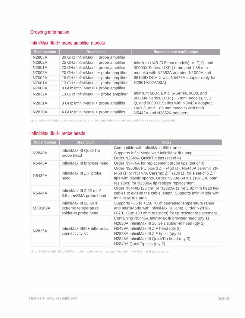
Ordering information
InfiniiMax III/III+ probe amplifier models
Model number Description Recommended oscilloscope
N2803A 30 GHz InfiniiMax III probe amplifier
Infiniium UXR (3.5 mm models), V, Z, Q, and
90000X Series, UXR (1 mm and 1.85 mm
models) with N2852A adapter, N1000A and
86100D DCA-X with N5477A adapter (only for
N2801A/02A/03A)
N2802A 25 GHz InfiniiMax III probe amplifier
N2801A 20 GHz InfiniiMax III probe amplifier
N7003A 20 GHz InfiniiMax III+ probe amplifier
N7002A 16 GHz InfiniiMax III+ probe amplifier
N7001A 13 GHz InfiniiMax III+ probe amplifier
N7000A 8 GHz InfiniiMax III+ probe amplifier
N2832A 13 GHz InfiniiMax III+ probe amplifier Infiniium MXR, EXR, S-Series, 9000, and
90000A Series, UXR (3.5 mm models), V, Z,
Q, and 90000X Series with N5442A adapter,
UXR (1 and 1.85 mm models) with both
N5442A and N2852A adapters
N2831A 8 GHz InfiniiMax III+ probe amplifier
N2830A 4 GHz InfiniiMax III+ probe amplifier
Note: InfiniiMax III and III+ probe amps are not compatible with existing InfiniiMax I or II probe heads.
InfiniiMax III/III+ probe heads
Model number Description Notes
N2848A InfiniiMax III QuickTip
probe head
Compatible with InfiniiMax III/III+ amp
Supports InfiniiMode with InfiniiMax III+ amp
Order N2849A QuickTip tips (set of 4)
N5445A InfiniiMax III browser head Order N5476A for replacement probe tips (set of 4)
N5439A InfiniiMax III ZIF probe
head
Order N2838A PC board ZIF (450 Ω), N5440A ceramic ZIF
(450 Ω) or N5447A Ceramic ZIF (200 Ω) for a set of 5 ZIF
tips with plastic sporks. Order N2838-68701 (10x 130 ohm
resistors) for N2838A tip resistor replacement.
N5444A InfiniiMax III 2.92 mm/
3.5 mm/SMA probe head
Order N5448B (25 cm) or N2823A (1 m) 2.92 mm head flex
cables to extend the cable length. Supports InfiniiMode with
InfiniiMax III+ amp
MX0109A
InfiniiMax III 26 GHz
extreme temperature
solder-in probe head
Supports –55 to +150 °C of operating temperature range
and InfiniiMode with InfiniiMax III+ amp. Order N2838-
68701 (10x 130 ohm resistors) for tip resistor replacement.
N2835A InfiniiMax III/III+ differential
connectivity kit
Containing N5445A InfiniiMax III browser head (qty 1)
N2836A InfiniiMax III 26 GHz solder-in head (qty 2)
N5439A InfiniiMax III ZIF head (qty 2)
N2838A InfiniiMax III ZIF tip kit (qty 2)
N2848A InfiniiMax III QuickTip head (qty 2)
N2849A QuickTip tips (qty 2)
Note: N54xxA InfiniiMax III/III+ probe heads are not compatible with InfiniiMax I or II probe amps.
Find us at www.keysight.com Page 27
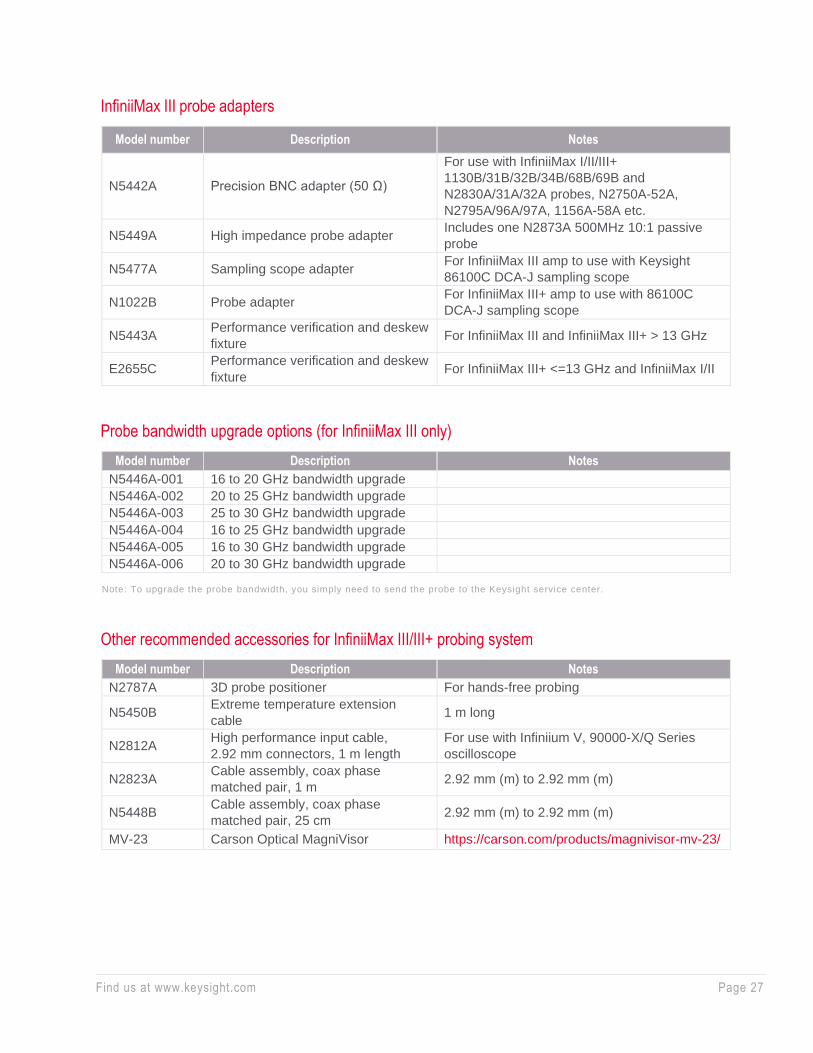
InfiniiMax III probe adapters
Model number Description Notes
N5442A Precision BNC adapter (50 Ω)
For use with InfiniiMax I/II/III+
1130B/31B/32B/34B/68B/69B and
N2830A/31A/32A probes, N2750A-52A,
N2795A/96A/97A, 1156A-58A etc.
N5449A High impedance probe adapter Includes one N2873A 500MHz 10:1 passive
probe
N5477A Sampling scope adapter For InfiniiMax III amp to use with Keysight
86100C DCA-J sampling scope
N1022B Probe adapter For InfiniiMax III+ amp to use with 86100C
DCA-J sampling scope
N5443A Performance verification and deskew
fixture For InfiniiMax III and InfiniiMax III+ > 13 GHz
E2655C Performance verification and deskew
fixture For InfiniiMax III+ <=13 GHz and InfiniiMax I/II
Probe bandwidth upgrade options (for InfiniiMax III only)
Model number Description Notes
N5446A-001 16 to 20 GHz bandwidth upgrade
N5446A-002 20 to 25 GHz bandwidth upgrade
N5446A-003 25 to 30 GHz bandwidth upgrade
N5446A-004 16 to 25 GHz bandwidth upgrade
N5446A-005 16 to 30 GHz bandwidth upgrade
N5446A-006 20 to 30 GHz bandwidth upgrade
Note: To upgrade the probe bandwidth, you simply need to send the probe to the Keysight service center.
Other recommended accessories for InfiniiMax III/III+ probing system
Model number Description Notes
N2787A 3D probe positioner For hands-free probing
N5450B Extreme temperature extension
cable 1 m long
N2812A High performance input cable,
2.92 mm connectors, 1 m length
For use with Infiniium V, 90000-X/Q Series
oscilloscope
N2823A Cable assembly, coax phase
matched pair, 1 m 2.92 mm (m) to 2.92 mm (m)
N5448B Cable assembly, coax phase
matched pair, 25 cm 2.92 mm (m) to 2.92 mm (m)
MV-23 Carson Optical MagniVisor https://carson.com/products/magnivisor-mv-23/

Find us at www.keysight.com Page 28
InfiniiMax Gen II Probes
Key features
• Up to 13 GHz bandwidth for differential, solder-in, browser, and SMA
connections
• Low noise and flat frequency response
• Industry’s widest variety of differential probe head types
Scope compatibility
See the table on page 3.
The InfiniiMax II Series 1168B/69B probing system provides real-time
bandwidth to 12 GHz specified and has 13 GHz typical performance. The
innovative InfiniiMax probing system supports even the most demanding
mechanical access requirements without sacrificing performance.

Find us at www.keysight.com Page 29
Characterized performance plots: 1169B with N5381B differential solder-in probe head
Graph of Vin and Vout of 1169B and N5381B solder-in head with a 25 Ω 58 psec step generator
Frequency response of 1169B and N5381B with a 25 Ω source
Common mode rejection ratio of 1169B

Find us at www.keysight.com Page 30
Ordering information
InfiniiMax II Series probe amplifiers
Model number Bandwidth Description
1169B 12 GHz (spec) 13 GHz
(typical)
InfiniiMax II probe amplifier – order one or more
probe heads
1168B 10 GHz InfiniiMax II probe amplifier – order one or more
probe heads
InfiniiMax probe amplif ier specifications: Dynamic range = 3.3 V, DC offset range = ± 16 V, maximum voltage = ± 30 V.
InfiniiMax II Series probe heads
InfiniiMax II Series probe heads are recommended for 1168B/69B probe amplifiers. When used with a
compatible Infiniium oscilloscope with >12 GHz bandwidth, the MX0100A, N5380B, N5381B, and
N2839A will typically achieve 13 GHz bandwidth.
Probe head Model number Differential measurement
(BW, input C, input R)
Single-ended measurement (BW,
input C, input R)
Hi-BW Micro probe
head MX0100A 12 GHz, 0.17 pF, 50 kΩ 12 GHz, 0.26 pF, 25 kΩ
Hi-BW differential SMA N5380B 12 GHz 12 GHz
Hi-BW differential
solder-in N5381B 12 GHz, 0.21 pF, 50 kΩ 12 GHz, 0.35 pF, 25 kΩ
ZIF solder-in
N5425B
with N5426A 12 GHz, 0.33 pF, 50 kΩ 12 GHz, 0.53 pF, 25 kΩ
with N5451A 7 mm,
0 deg 9.9 GHz, — , 50 kΩ 9.9 GHz, 0.6 pF, 25 kΩ
with N5451A 11 mm,
0 deg 5 GHz, — , 50 kΩ 5 GHz, 0.68 pF, 25 kΩ
with N2884A 12 GHz, 350 fF, 50 kΩ 12 GHz, 320 fF, 25k Ω
QuickTip N2851A head with
N2849A tips 12 GHz, 0.2 pF, 50 kΩ 12 GHz, 0.34 pF, 25 kΩ
Hi-BW differential
browser N2839A 12 GHz, 0.21 pF, 50 kΩ 12 GHz, 0.34 pF, 25 kΩ
InfiniiMax II differential
connectivity kit N2833A
Containing N2839A InfiniiMax II browser head
(qty 1)
N5381B InfiniiMax II solder-in head (qty 2)
N5425B InfiniiMax II ZIF head (qty 2)
N5426A ZIF tip kit (qty 2)
N2851A InfiniiMax II QuickTip head (qty 2)
N2849A QuickTip tips (qty 2)
Find us at www.keysight.com Page 31
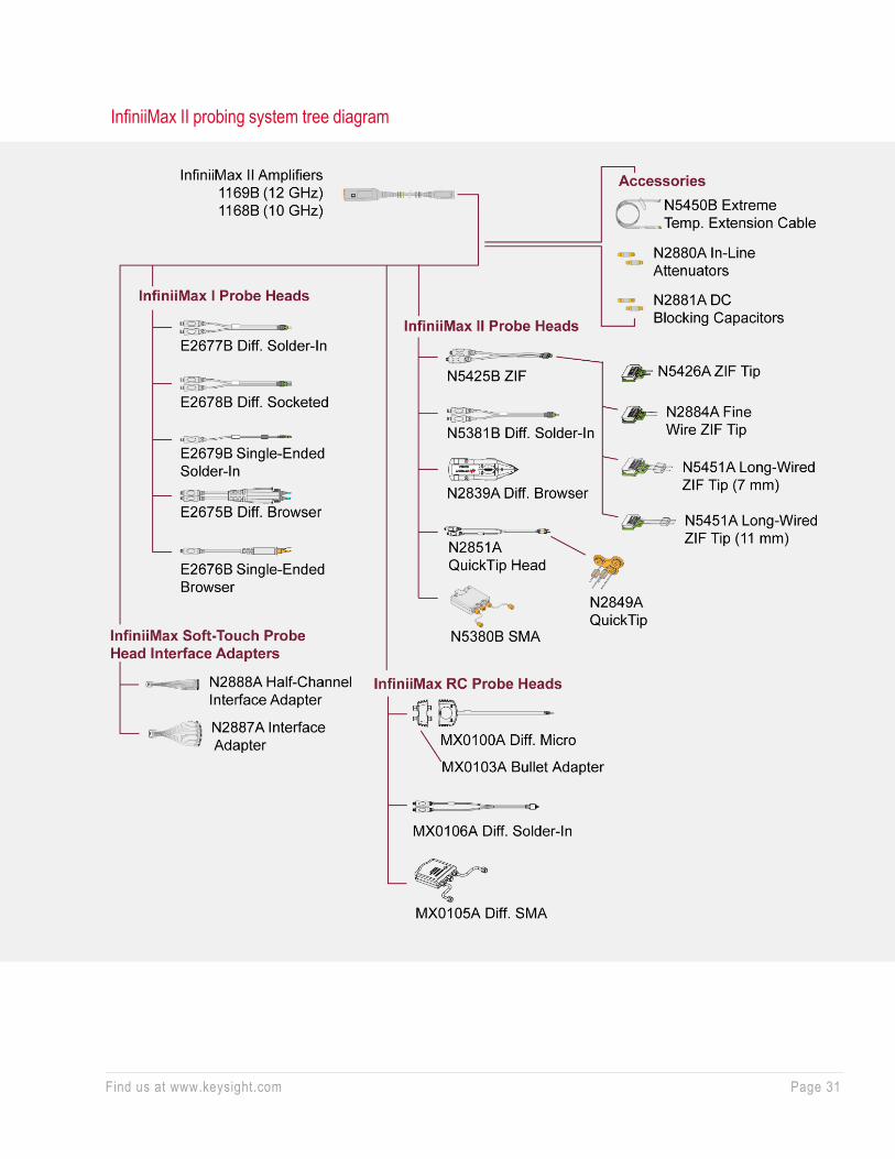
InfiniiMax II probing system tree diagram
Find us at www.keysight.com Page 32
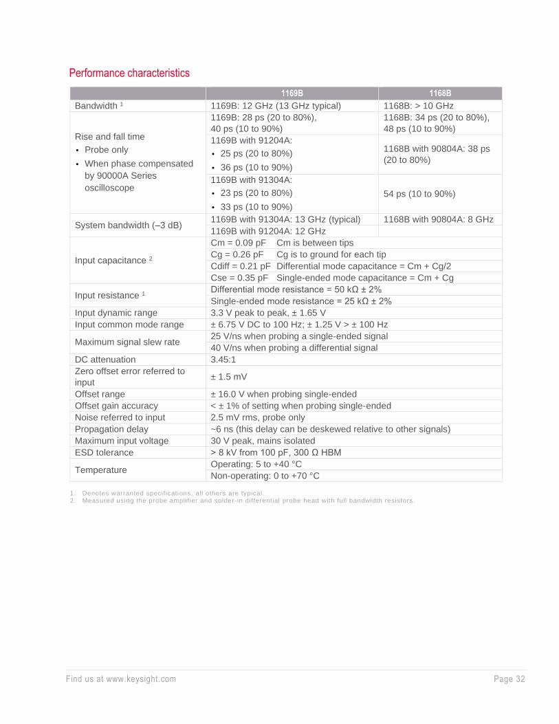
Performance characteristics
1169B 1168B
Bandwidth 1 1169B: 12 GHz (13 GHz typical) 1168B: > 10 GHz
Rise and fall time
• Probe only
• When phase compensated
by 90000A Series
oscilloscope
1169B: 28 ps (20 to 80%),
40 ps (10 to 90%)
1168B: 34 ps (20 to 80%),
48 ps (10 to 90%)
1169B with 91204A:
• 25 ps (20 to 80%)
• 36 ps (10 to 90%)
1168B with 90804A: 38 ps
(20 to 80%)
1169B with 91304A:
• 23 ps (20 to 80%)
• 33 ps (10 to 90%)
54 ps (10 to 90%)
System bandwidth (–3 dB) 1169B with 91304A: 13 GHz (typical) 1168B with 90804A: 8 GHz
1169B with 91204A: 12 GHz
Input capacitance 2
Cm = 0.09 pF Cm is between tips
Cg = 0.26 pF Cg is to ground for each tip
Cdiff = 0.21 pF Differential mode capacitance = Cm + Cg/2
Cse = 0.35 pF Single-ended mode capacitance = Cm + Cg
Input resistance 1 Differential mode resistance = 50 kΩ ± 2%
Single-ended mode resistance = 25 kΩ ± 2%
Input dynamic range 3.3 V peak to peak, ± 1.65 V
Input common mode range ± 6.75 V DC to 100 Hz; ± 1.25 V > ± 100 Hz
Maximum signal slew rate 25 V/ns when probing a single-ended signal
40 V/ns when probing a differential signal
DC attenuation 3.45:1
Zero offset error referred to
input ± 1.5 mV
Offset range ± 16.0 V when probing single-ended
Offset gain accuracy < ± 1% of setting when probing single-ended
Noise referred to input 2.5 mV rms, probe only
Propagation delay ~6 ns (this delay can be deskewed relative to other signals)
Maximum input voltage 30 V peak, mains isolated
ESD tolerance > 8 kV from 100 pF, 300 Ω HBM
Temperature Operating: 5 to +40 °C
Non-operating: 0 to +70 °C
1. Denotes warranted specifications, all others are typical. 2. Measured using the probe amplifier and solder-in differential probe head with full bandwidth resistors.

Find us at www.keysight.com Page 33
InfiniiMax Gen I Probes
Key features
• Up to 7 GHz bandwidth for differential, solder-in, browser, and SMA connections
• Low noise and flat frequency response
• Wide dynamic range (± 2.5 V) and offset range (± 12 V)
Scope compatibility
See the table on page 3.
For high-speed differential or single-ended probing in embedded designs, the InfiniiMax 1130B Series
differential probe amplifiers are perfect complements to the Infiniium 600 MH to 6 GHz oscilloscopes. Its
extremely low input capacitance, flat frequency response and the patented resistor probe tip technology
provide ultra low loading of the DUT and superior signal fidelity.
Characterized performance plots: with E2677B differential solder-in probe head
Vin and Vout of probe with a 25-Ω, 100 psec step
signal
Swept frequency response with a 25-Ω source
Probe input impedance versus frequency Common mode rejection versus frequency
Find us at www.keysight.com Page 34
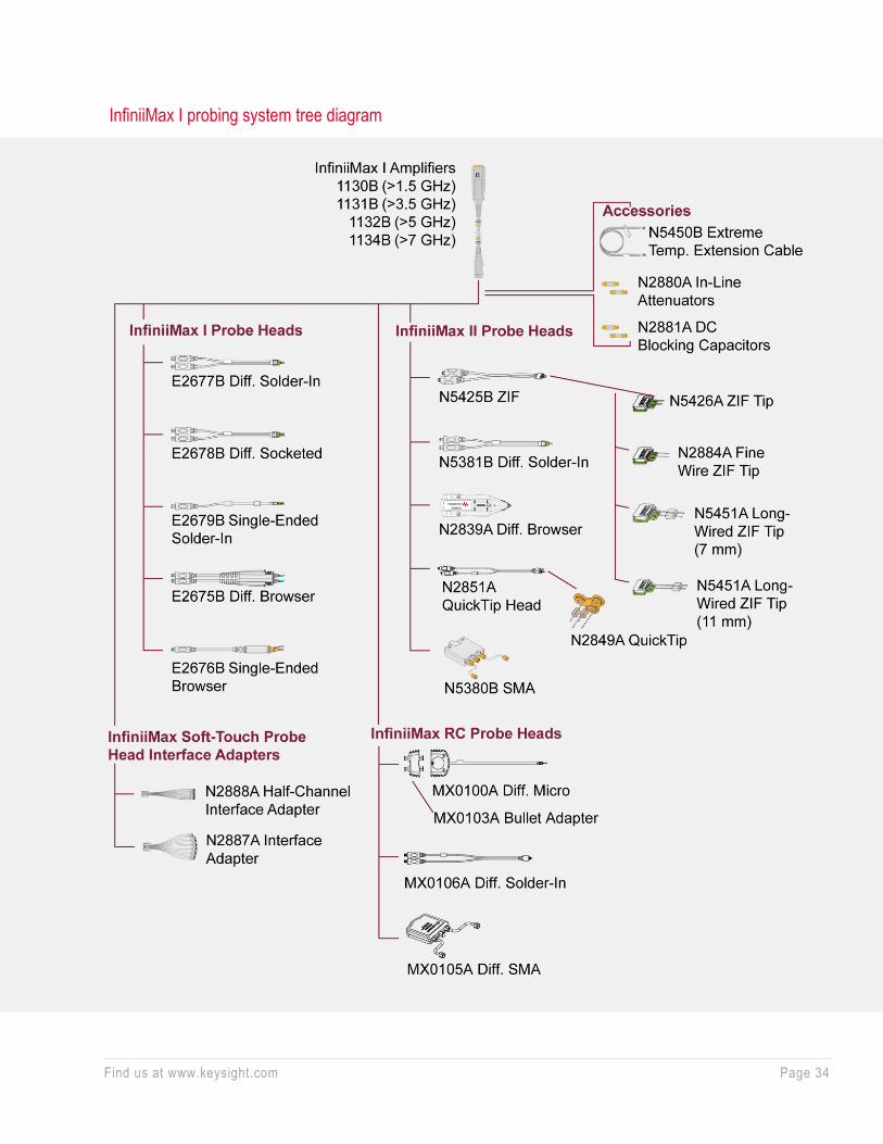
InfiniiMax I probing system tree diagram
Find us at www.keysight.com Page 35
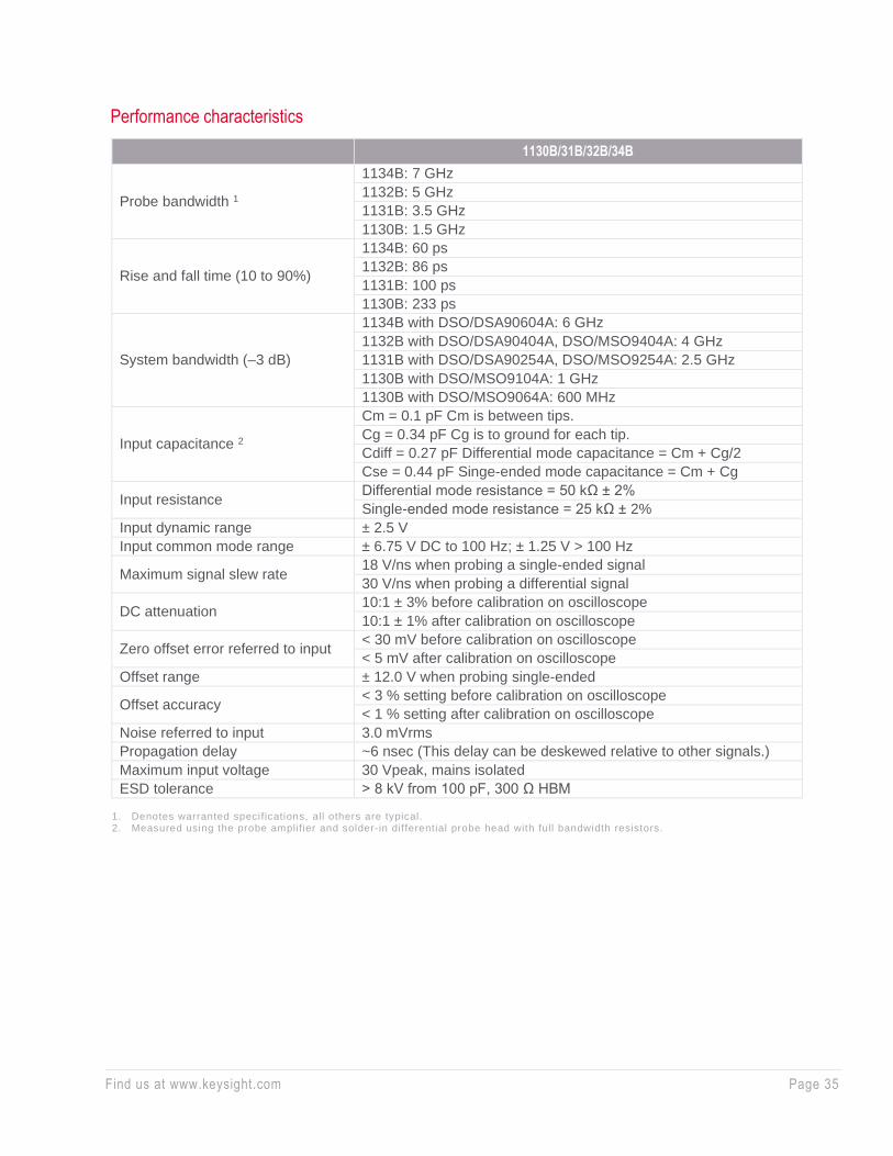
Performance characteristics
1130B/31B/32B/34B
Probe bandwidth 1
1134B: 7 GHz
1132B: 5 GHz
1131B: 3.5 GHz
1130B: 1.5 GHz
Rise and fall time (10 to 90%)
1134B: 60 ps
1132B: 86 ps
1131B: 100 ps
1130B: 233 ps
System bandwidth (–3 dB)
1134B with DSO/DSA90604A: 6 GHz
1132B with DSO/DSA90404A, DSO/MSO9404A: 4 GHz
1131B with DSO/DSA90254A, DSO/MSO9254A: 2.5 GHz
1130B with DSO/MSO9104A: 1 GHz
1130B with DSO/MSO9064A: 600 MHz
Input capacitance 2
Cm = 0.1 pF Cm is between tips.
Cg = 0.34 pF Cg is to ground for each tip.
Cdiff = 0.27 pF Differential mode capacitance = Cm + Cg/2
Cse = 0.44 pF Singe-ended mode capacitance = Cm + Cg
Input resistance Differential mode resistance = 50 kΩ ± 2%
Single-ended mode resistance = 25 kΩ ± 2%
Input dynamic range ± 2.5 V
Input common mode range ± 6.75 V DC to 100 Hz; ± 1.25 V > 100 Hz
Maximum signal slew rate 18 V/ns when probing a single-ended signal
30 V/ns when probing a differential signal
DC attenuation 10:1 ± 3% before calibration on oscilloscope
10:1 ± 1% after calibration on oscilloscope
Zero offset error referred to input < 30 mV before calibration on oscilloscope
< 5 mV after calibration on oscilloscope
Offset range ± 12.0 V when probing single-ended
Offset accuracy < 3 % setting before calibration on oscilloscope
< 1 % setting after calibration on oscilloscope
Noise referred to input 3.0 mVrms
Propagation delay ~6 nsec (This delay can be deskewed relative to other signals.)
Maximum input voltage 30 Vpeak, mains isolated
ESD tolerance > 8 kV from 100 pF, 300 Ω HBM
1. Denotes warranted specifications, all others are typical. 2. Measured using the probe amplifier and solder-in differential probe head with full bandwidth resistors.
Find us at www.keysight.com Page 36
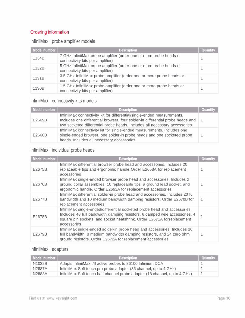
Ordering information
InfiniiMax I probe amplifier models
Model number Description Quantity
1134B 7 GHz InfiniiMax probe amplifier (order one or more probe heads or
connectivity kits per amplifier) 1
1132B 5 GHz InfiniiMax probe amplifier (order one or more probe heads or
connectivity kits per amplifier) 1
1131B 3.5 GHz InfiniiMax probe amplifier (order one or more probe heads or
connectivity kits per amplifier) 1
1130B 1.5 GHz InfiniiMax probe amplifier (order one or more probe heads or
connectivity kits per amplifier) 1
InfiniiMax I connectivity kits models
Model number Description Quantity
E2669B
InfiniiMax connectivity kit for differential/single-ended measurements.
Includes one differential browser, four solder-in differential probe heads and
two socketed differential probe heads. Includes all necessary accessories
1
E2668B
InfiniiMax connectivity kit for single-ended measurements. Includes one
single-ended browser, one solder-in probe heads and one socketed probe
heads. Includes all necessary accessories
1
InfiniiMax I individual probe heads
Model number Description Quantity
E2675B
InfiniiMax differential browser probe head and accessories. Includes 20
replaceable tips and ergonomic handle. Order E2658A for replacement
accessories
1
E2676B
InfiniiMax single-ended browser probe head and accessories. Includes 2
ground collar assemblies, 10 replaceable tips, a ground lead socket, and
ergonomic handle. Order E2663A for replacement accessories
1
E2677B
InfiniiMax differential solder-in probe head and accessories. Includes 20 full
bandwidth and 10 medium bandwidth damping resistors. Order E2670B for
replacement accessories
1
E2678B
InfiniiMax single-ended/differential socketed probe head and accessories.
Includes 48 full bandwidth damping resistors, 6 damped wire accessories, 4
square pin sockets, and socket heatshrink. Order E2671A for replacement
accessories
1
E2679B
InfiniiMax single-ended solder-in probe head and accessories. Includes 16
full bandwidth, 8 medium bandwidth damping resistors, and 24 zero ohm
ground resistors. Order E2672A for replacement accessories
1
InfiniiMax I adapters
Model number Description Quantity
N1022B Adapts InfiniiMax I/II active probes to 86100 Infiniium DCA 1
N2887A InfiniiMax Soft touch pro probe adapter (36 channel, up to 4 GHz) 1
N2888A InfiniiMax Soft touch half-channel probe adapter (18 channel, up to 4 GHz) 1

Find us at www.keysight.com Page 37
Optical-to-Electrical Converters — N7005A 60 GHz
• DC to 60 GHz typical (–3 dBe, electrical)
• Single-mode input
• 9/125 µm, 1250 nm - 1600 nm (covers main wavelengths: 1310 nm, and 1550 nm)
• FlexDCA SW supports PAM4 measurement capabilities such as TDECQ
• Optical measurement features built into the Infiniium UXR baseline software version
• 10.25 patch or higher
• Compatible with Infiniium UXR oscilloscope with ≥ 40 GHz bandwidth
The N7005A is a 60 GHz (-3 dB, Brickwall) O/E converter compatible with Keysight UXR oscilloscope
with 1.85 mm or 1 mm input. The frequency response of a DSP corrected N7005A is either flat to up to
60 GHz Brickwall response or it follows a 4th order Bessel Thomson response until it hits the Brickwall
at 70 GHz. The N7005A used in conjunction with 70 GHz Infiniium UXR oscilloscope supports 4th order
Bessel Thomson response to view optical streams at speeds up to 56 Gbaud PAM4, making this the
ideal solution for characterizing or troubleshooting high-speed optical signals in system level testing and
debugging.
Infiniium UXR baseline software v 10.25 patch or higher covers basic optical measurement features and
dark calibration. The FlexRT measurement software installed on Infiniium UXR oscilloscope supports
deep analysis of PAM4 signaling measurement capabilities such as TDECQ.

Find us at www.keysight.com Page 38
Optical-to-Electrical Converters — N7004A 33 GHz
• DC to 33 GHz typical (–3 dBe, electrical)
• Single-mode and multimode inputs
• 50/125 μm, 750 to 1650 nm (covers main
wavelengths: 850 nm, 1310 nm, and 1550 nm)
• Designed for reference receiver testing of industry
optical standards or characterizing raw response
of an optical transmitter
• Optical measurement features built into the
Infiniium baseline software version 05.70 or
higher
• Compatible with Infiniium UXR, V-Series, 90000
X-Series, Z-Series and discontinued 90000 Q-
Series real-time oscilloscopes
The Keysight N7004A optical-to-electrical converter is a high-sensitivity photodetector module designed
for direct optical-to-electrical conversion of optical telecom or data com signals into an Infiniium real-time
oscilloscope with AutoProbe II interface.
The N7004A is the first fully-integrated optical-to-electrical converter solution for Infiniium real- time
oscilloscopes. A full suite of optical measurement software is built into the Infiniium baseline software v
05.70 and is offered at no additional cost. The N7004A comes in a compact form factor that is plugged
directly into the AutoProbe II probe interface of the Infiniium oscilloscope.
The adapter provides from DC to 33 GHz of electrical bandwidth. When used with an Infiniium V-Series
or Z-Series 33 GHz oscilloscope, the N7004A allows users to view optical streams at speeds up to 28
Gbps, making this the ideal solution for characterizing or troubleshooting high-speed optical signals in
the system level testing. The N7004A with an Infiniium real-time oscilloscope is the ideal solution for
users who want to see the unfiltered response of optical transmissions as well.
Each N7004A adapter contains its unique S-parameter correction filter, and this frequency response
data is used to flatten the frequency response for more accurate measurement.
The input is a 50 μm/125 μm fiber that can be used with 9 μm single-mode fiber or 50 μm multimode
fiber at wavelengths from 750 to 1650 nm and has a FC/PC adaptor. The reference receiver
measurement is made with a built-in 4th order Bessel Thomson software filter that allows the waveform
to be viewed similarly to what an optical receiver in an actual communication system would display. The
4th order Bessel Thomson filter bandwidth is limited to 2/3 of the Brickwall bandwidth of the
oscilloscope. For a 33 GHz oscilloscope with the Bessel Thomson filter on, this yields a 22 GHz Bessel
Thomson filter, which covers 28 Gbps x 0.75 = 21 GHz.
Find us at www.keysight.com Page 39
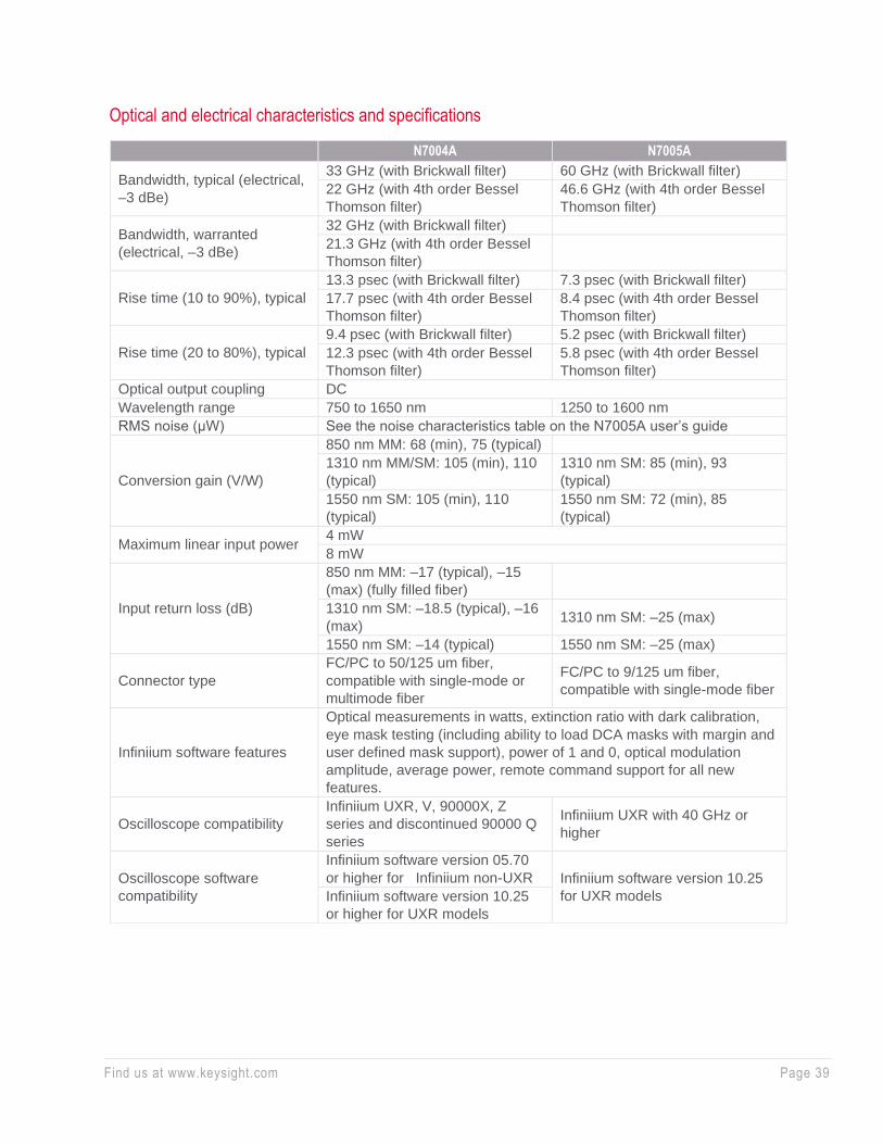
Optical and electrical characteristics and specifications
N7004A N7005A
Bandwidth, typical (electrical,
–3 dBe)
33 GHz (with Brickwall filter) 60 GHz (with Brickwall filter)
22 GHz (with 4th order Bessel
Thomson filter)
46.6 GHz (with 4th order Bessel
Thomson filter)
Bandwidth, warranted
(electrical, –3 dBe)
32 GHz (with Brickwall filter)
21.3 GHz (with 4th order Bessel
Thomson filter)
Rise time (10 to 90%), typical
13.3 psec (with Brickwall filter) 7.3 psec (with Brickwall filter)
17.7 psec (with 4th order Bessel
Thomson filter)
8.4 psec (with 4th order Bessel
Thomson filter)
Rise time (20 to 80%), typical
9.4 psec (with Brickwall filter) 5.2 psec (with Brickwall filter)
12.3 psec (with 4th order Bessel
Thomson filter)
5.8 psec (with 4th order Bessel
Thomson filter)
Optical output coupling DC
Wavelength range 750 to 1650 nm 1250 to 1600 nm
RMS noise (μW) See the noise characteristics table on the N7005A user’s guide
Conversion gain (V/W)
850 nm MM: 68 (min), 75 (typical)
1310 nm MM/SM: 105 (min), 110
(typical)
1310 nm SM: 85 (min), 93
(typical)
1550 nm SM: 105 (min), 110
(typical)
1550 nm SM: 72 (min), 85
(typical)
Maximum linear input power 4 mW
8 mW
Input return loss (dB)
850 nm MM: –17 (typical), –15
(max) (fully filled fiber)
1310 nm SM: –18.5 (typical), –16
(max) 1310 nm SM: –25 (max)
1550 nm SM: –14 (typical) 1550 nm SM: –25 (max)
Connector type
FC/PC to 50/125 um fiber,
compatible with single-mode or
multimode fiber
FC/PC to 9/125 um fiber,
compatible with single-mode fiber
Infiniium software features
Optical measurements in watts, extinction ratio with dark calibration,
eye mask testing (including ability to load DCA masks with margin and
user defined mask support), power of 1 and 0, optical modulation
amplitude, average power, remote command support for all new
features.
Oscilloscope compatibility
Infiniium UXR, V, 90000X, Z
series and discontinued 90000 Q
series
Infiniium UXR with 40 GHz or
higher
Oscilloscope software
compatibility
Infiniium software version 05.70
or higher for Infiniium non-UXR Infiniium software version 10.25
for UXR models Infiniium software version 10.25
or higher for UXR models
Find us at www.keysight.com Page 40
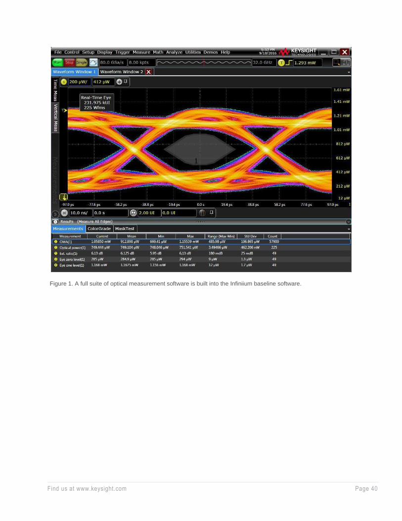
Figure 1. A full suite of optical measurement software is built into the Infiniium baseline software.
Find us at www.keysight.com Page 41
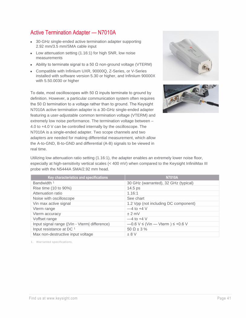
Active Termination Adapter — N7010A
• 30-GHz single-ended active termination adapter supporting
2.92 mm/3.5 mm/SMA cable input
• Low attenuation setting (1.16:1) for high SNR, low noise
measurements
• Ability to terminate signal to a 50 Ω non-ground voltage (VTERM)
• Compatible with Infiniium UXR, 90000Q, Z-Series, or V-Series
installed with software version 5.30 or higher, and Infiniium 90000X
with 5.50.0030 or higher
To date, most oscilloscopes with 50 Ω inputs terminate to ground by
definition. However, a particular communication system often requires
the 50 Ω termination to a voltage rather than to ground. The Keysight
N7010A active termination adapter is a 30-GHz single-ended adapter
featuring a user-adjustable common termination voltage (VTERM) and
extremely low noise performance. The termination voltage between –
4.0 to +4.0 V can be controlled internally by the oscilloscope. The
N7010A is a single-ended adapter. Two scope channels and two
adapters are needed for making differential measurement, which allow
the A-to-GND, B-to-GND and differential (A-B) signals to be viewed in
real time.
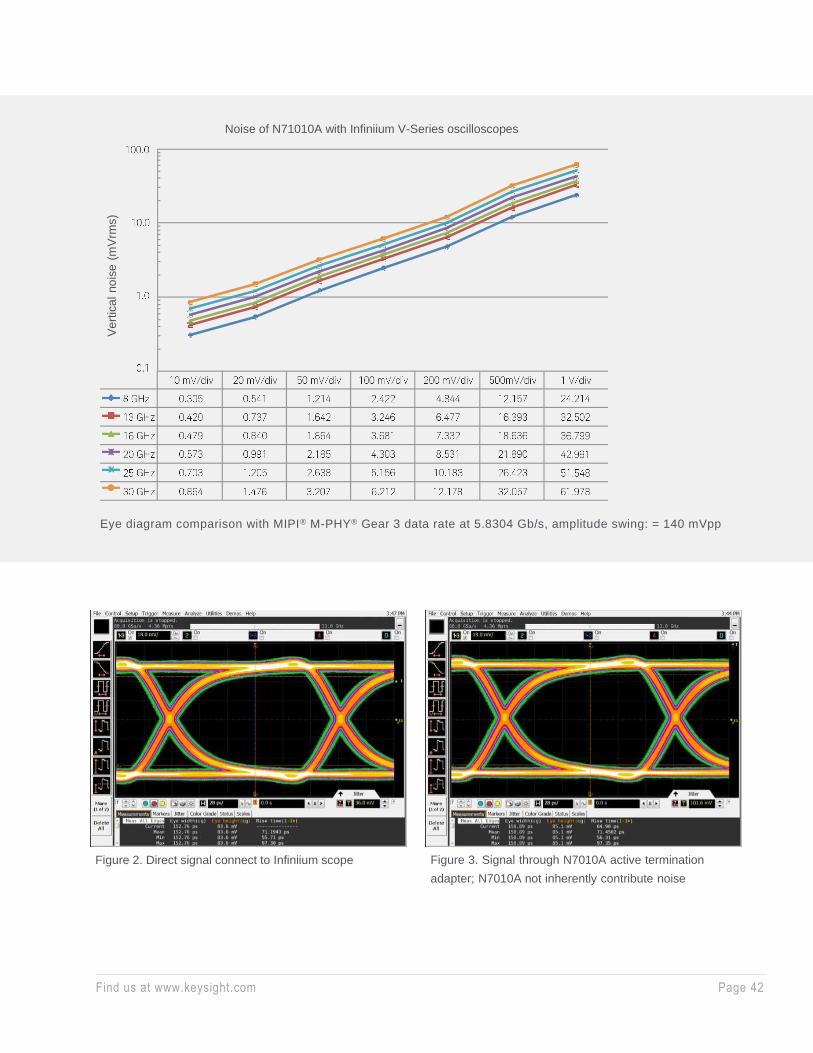
Utilizing low attenuation ratio setting (1.16:1), the adapter enables an extremely lower noise floor,
especially at high-sensitivity vertical scales (< 400 mV) when compared to the Keysight InfiniiMax III
probe with the N5444A SMA/2.92 mm head.
Key characteristics and specifications N7010A
Bandwidth 1 30 GHz (warranted), 32 GHz (typical)
Rise time (10 to 90%) 14.5 ps
Attenuation ratio 1.16:1
Noise with oscilloscope See chart
Vin max active signal 1.2 Vpp (not including DC component)
Vterm range —4 to +4 V
Vterm accuracy ± 2 mV
Voffset range —4 to +4 V
Input signal range (|Vin - Vterm| difference) —0.6 V ≤ (Vin — Vterm ) ≤ +0.6 V
Input resistance at DC 1 50 Ω ± 3 %
Max non-destructive input voltage ± 8 V
1. Warranted specifications.
Find us at www.keysight.com Page 42
Figure 2. Direct signal connect to Infiniium scope Figure 3. Signal through N7010A active termination
adapter; N7010A not inherently contribute noise
Eye diagram comparison with MIPI® M-PHY® Gear 3 data rate at 5.8304 Gb/s, amplitude swing: = 140 mVpp
Noise of N71010A with Infiniium V-Series oscilloscopes
Ve
rtic
al no
ise
(m
Vrm
s)

Find us at www.keysight.com Page 43
InfiniiMode Active Probes — N2750A/51A/52A
InfiniiMode active probes N2750A/51A/52A InfiniiMode probes
• 1.5, 3.5, and 6 GHz probe bandwidth models
• Dual attenuation ratio (2:1/10:1)
• High input resistance (200 kΩ differential, 100 kΩ single-ended)
• Wide input dynamic range (10 Vpp) and offset range (± 15 V)
• High CMRR (> 60 dB at 1 MHz)
• InfiniiMode probing for making differential, single-ended, and
common mode measurements with a single probe
• Built-in quick action scope control for quick access to a variety of
scope functions
• Built-in headlight
• Includes solder-in, browser, and socketed tips standard
• AutoProbe interface for auto configuration and probe power for
Infiniium scopes
Measurement versatility
The N2750A Series differential probes offer 2:1 and 10:1 dual attenuation settings, allowing them to be
used for a broad range of applications. Dual attenuation range is automatically configured depending on
the size of the input signal.
The new differential probes have an input resistance of 200 kΩ (differential) or 100 kΩ (each input to
ground) and an extremely low input capacitance of 700 fF to minimize circuit loading. This,
accompanied with superior signal fidelity, makes these probes useful for most digital design and debug
applications. And with their wide dynamic range (10 Vpp) and offset range (± 15 V), these probes can
be used in a wide variety of analog signal measurements as well.
InfiniiMode usability
The N2750A Series probes come with new InfiniiMode operation modes. The InfiniiMode allows
convenient measurements of differential, single- ended, and common mode signals with a single probe
tip without reconnecting the probe to change the connection. The N2750A probe’s InfiniiMode provides
the following modes of operation.
• A – B (differential)
• A – ground (single-ended A)
• B – ground (single-ended B)
• (A+B)/2 – ground (common mode)
The N2750A Series InfiniiMode differential
probes are a new generation of low-cost,
1.5, 3.5, and 6 GHz differential active
probes compatible with Infiniium
oscilloscope’s AutoProbe interface
Find us at www.keysight.com Page 44
Quick action scope control
The N2750A Series differential probes provide convenient and quick access to various functions on the
scope. You often have a need to control the scope while you hold a probe in your hand. With the quick
action scope control feature built into the probe, you can turn the built-in headlight of the probe on and
off or control some frequently used scope functions, such as RUN/STOP, auto scale, quick print, and
quick save with only the push of a button on the probe. Get control of your most needed function with a
push of the quick action control button on the probe.
Flexibility in probe use models is also a vital necessity. The probes come standard with three different
types of exchangeable probe tips that allow for easy connections to the circuit under test. These probe
tips enable you to access multiple signals on anything from header connectors to hard-to- reach, high-
density circuitry. The probes are equipped with a white LED headlight to illuminate the circuit under test
which will help you see where you are probing.
The probes are powered directly by the Infiniium AutoProbe interface, eliminating the need for an
additional power supply.
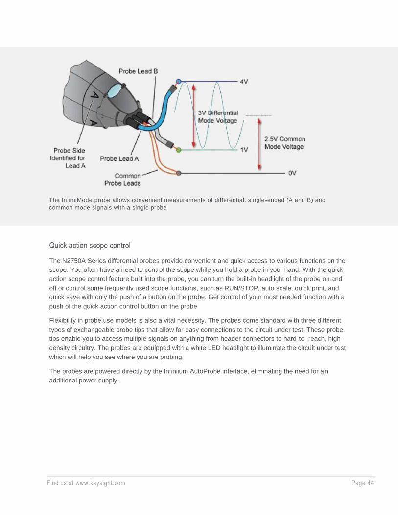
The InfiniiMode probe allows convenient measurements of differential, single-ended (A and B) and
common mode signals with a single probe
Find us at www.keysight.com Page 45
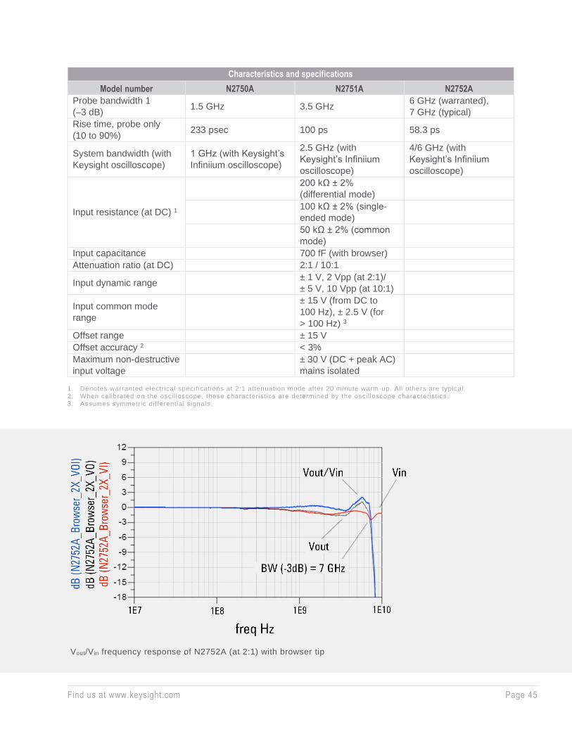
Characteristics and specifications
Model number N2750A N2751A N2752A
Probe bandwidth 1
(–3 dB) 1.5 GHz 3.5 GHz
6 GHz (warranted),
7 GHz (typical)
Rise time, probe only
(10 to 90%) 233 psec 100 ps 58.3 ps
System bandwidth (with
Keysight oscilloscope)
1 GHz (with Keysight’s
Infiniium oscilloscope)
2.5 GHz (with
Keysight’s Infiniium
oscilloscope)
4/6 GHz (with
Keysight’s Infiniium
oscilloscope)
Input resistance (at DC) 1
200 kΩ ± 2%
(differential mode)
100 kΩ ± 2% (single-
ended mode)
50 kΩ ± 2% (common
mode)
Input capacitance 700 fF (with browser)
Attenuation ratio (at DC) 2:1 / 10:1
Input dynamic range ± 1 V, 2 Vpp (at 2:1)/
± 5 V, 10 Vpp (at 10:1)
Input common mode
range
± 15 V (from DC to
100 Hz), ± 2.5 V (for
> 100 Hz) 3
Offset range ± 15 V
Offset accuracy 2 < 3%
Maximum non-destructive
input voltage
± 30 V (DC + peak AC)
mains isolated
1. Denotes warranted electrical specifications at 2:1 attenuation mode after 20 minute warm-up. All others are typical. 2. When calibrated on the oscilloscope, these characteristics are determined by the oscilloscope characteristics. 3. Assumes symmetric differential signals.
Vout/Vin frequency response of N2752A (at 2:1) with browser tip
Find us at www.keysight.com Page 46
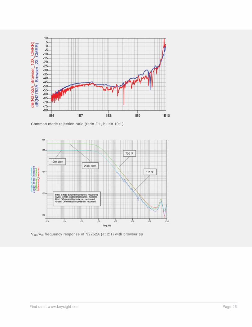
Common mode rejection ratio (red= 2:1, blue= 10:1)
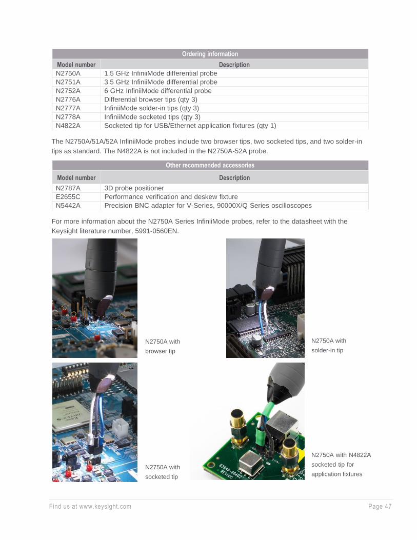
Vout/Vin frequency response of N2752A (at 2:1) with browser tip
Find us at www.keysight.com Page 47
Ordering information
Model number Description
N2750A 1.5 GHz InfiniiMode differential probe
N2751A 3.5 GHz InfiniiMode differential probe
N2752A 6 GHz InfiniiMode differential probe
N2776A Differential browser tips (qty 3)
N2777A InfiniiMode solder-in tips (qty 3)
N2778A InfiniiMode socketed tips (qty 3)
N4822A Socketed tip for USB/Ethernet application fixtures (qty 1)
The N2750A/51A/52A InfiniiMode probes include two browser tips, two socketed tips, and two solder-in
tips as standard. The N4822A is not included in the N2750A-52A probe.
Other recommended accessories
Model number Description
N2787A 3D probe positioner
E2655C Performance verification and deskew fixture
N5442A Precision BNC adapter for V-Series, 90000X/Q Series oscilloscopes
For more information about the N2750A Series InfiniiMode probes, refer to the data sheet with the
Keysight literature number, 5991-0560EN.
N2750A with
browser tip
N2750A with
socketed tip
N2750A with
solder-in tip
N2750A with N4822A
socketed tip for
application fixtures
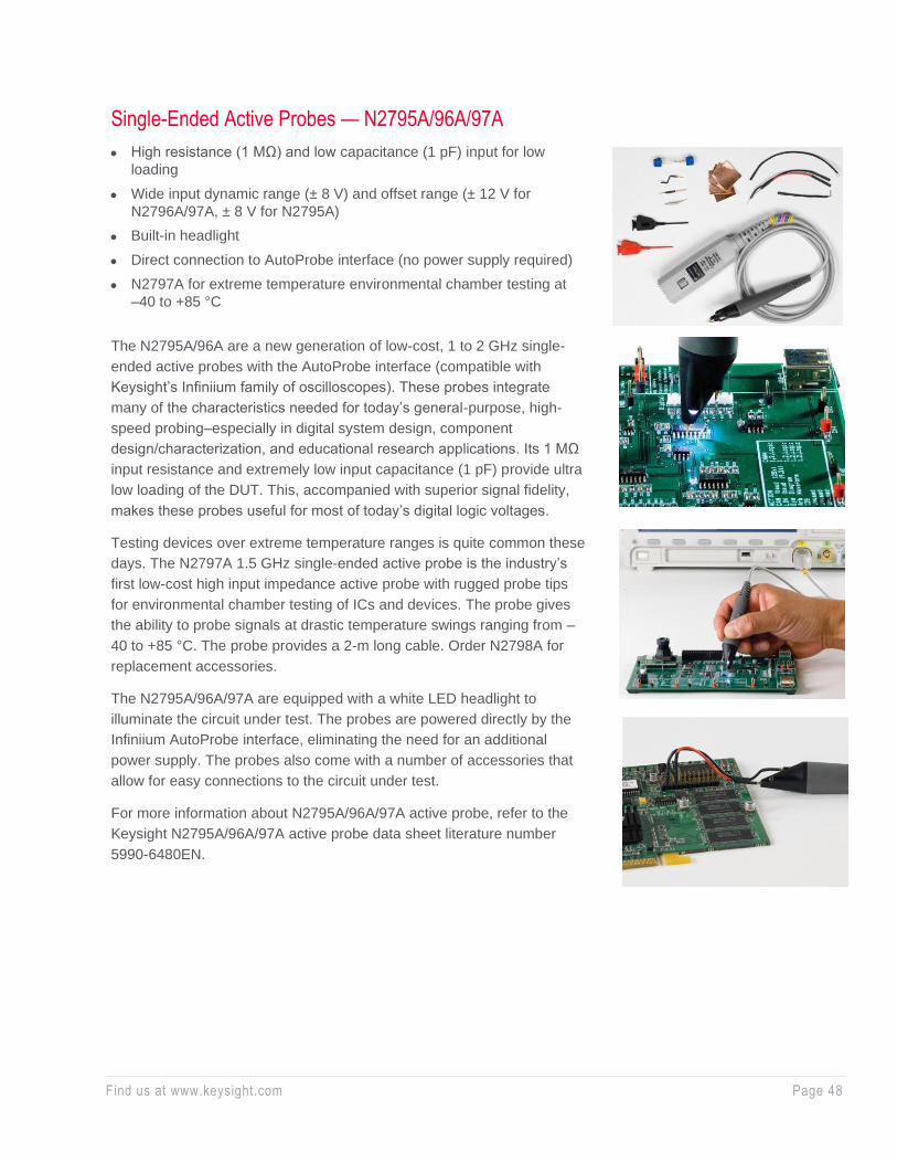
Find us at www.keysight.com Page 48
Single-Ended Active Probes — N2795A/96A/97A
• High resistance (1 MΩ) and low capacitance (1 pF) input for low
loading
• Wide input dynamic range (± 8 V) and offset range (± 12 V for
N2796A/97A, ± 8 V for N2795A)
• Built-in headlight
• Direct connection to AutoProbe interface (no power supply required)
• N2797A for extreme temperature environmental chamber testing at
–40 to +85 °C
The N2795A/96A are a new generation of low-cost, 1 to 2 GHz single-
ended active probes with the AutoProbe interface (compatible with
Keysight’s Infiniium family of oscilloscopes). These probes integrate
many of the characteristics needed for today’s general-purpose, high-
speed probing–especially in digital system design, component
design/characterization, and educational research applications. Its 1 MΩ
input resistance and extremely low input capacitance (1 pF) provide ultra
low loading of the DUT. This, accompanied with superior signal fidelity,
makes these probes useful for most of today’s digital logic voltages.
Testing devices over extreme temperature ranges is quite common these
days. The N2797A 1.5 GHz single-ended active probe is the industry’s
first low-cost high input impedance active probe with rugged probe tips
for environmental chamber testing of ICs and devices. The probe gives
the ability to probe signals at drastic temperature swings ranging from –
40 to +85 °C. The probe provides a 2-m long cable. Order N2798A for
replacement accessories.
The N2795A/96A/97A are equipped with a white LED headlight to
illuminate the circuit under test. The probes are powered directly by the
Infiniium AutoProbe interface, eliminating the need for an additional
power supply. The probes also come with a number of accessories that
allow for easy connections to the circuit under test.
For more information about N2795A/96A/97A active probe, refer to the
Keysight N2795A/96A/97A active probe data sheet literature number
5990-6480EN.

Find us at www.keysight.com Page 49
Characteristics for N2795A, N2796A, and N2797A active probes
N2795A N2796A N2797A
Probe bandwidth 1 (-3 dB) 1 GHz 2 GHz 1.5 GHz
Rise time 350 ps 175 ps 233 ps
System bandwidth
600 MHz (with Keysight’s
600 MHz Infiniium
oscilloscope)
1 GHz (with Keysight’s 1 GHz Infiniium
oscilloscope)
Attenuation ratio (at DC) 10:1 ± 0.5%
Input dynamic range -8 to +8 V (DC or peak AC)
Non-destructive input voltage -20 to +20 V mains isolated
Offset range ± 8 V ± 12 V
DC offset error (output zero) ± 1 mV
Low frequency accuracy 0.5% at 70 Hz, 1 Vpp
Input resistance 1 1 MΩ
Input capacitance 1 pF
Output impedance 50 Ω
1. Denotes warranted electrical specifications after 20 minute warm -up. All others are typical .
Measurement plots
Time domain step response of N2796A
(with Keysight MSO9404A)
Frequency response of N2796A (Vout/Vin)

Find us at www.keysight.com Page 50
Ordering information
Model number Description
N2795A 1 GHz single-ended active probe
N2796A 2 GHz single-ended active probe
N2797A 1.5 GHz single-ended active probe
Reorderable accessories
Model number Description Quantity
N4839A Dual-lead socketed adapter, 6 cm 2
N4840A Dual-lead solder-in adapter, 5 cm 2
N4841A Dual-lead socketed adapter, 9 cm 2
N4842A Dual-pin PCB header 2
N4843A Solderable tips 10
N4844A Right angle ground lead, 5 cm 2
N4845A Ground blade 2
N4846A Offset ground 2
N4839A N4840A N4841A N4842A
N4843A
N4845A
N4846A N4844A
N4843A
Input impedance over frequency (Red = measured,
Green = model)
N4845A
Voltage derating over frequency (N2796A)
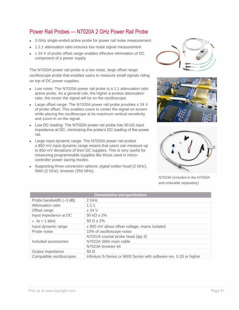
Find us at www.keysight.com Page 51
Power Rail Probes — N7020A 2 GHz Power Rail Probe
• 2-GHz single-ended active probe for power rail noise measurement
• 1.1:1 attenuation ratio ensures low noise signal measurement
• ± 24 V of probe offset range enables effective elimination of DC
component of a power supply
The N7020A power rail probe is a low noise, large offset range
oscilloscope probe that enables users to measure small signals riding
on top of DC power supplies.
• Low noise: The N7020A power rail probe is a 1:1 attenuation ratio
active probe. As a general rule, the higher a probes attenuation
ratio, the nosier the signal will be on the oscilloscope.
• Large offset range: The N7020A power rail probe provides ± 24 V
of probe offset. This enables users to center the signal on screen
while placing the oscilloscope at its maximum vertical sensitivity
and zoom-in on the signal.
• Low DC loading: The N7020A power rail probe has 50 kΩ input
impedance at DC, minimizing the probe’s DC loading of the power
rail.
• Large input dynamic range: The N7020A power rail probes
± 850 mV input dynamic range means that users can measure up
to 850 mV deviations of their DC supplies. This is very useful for
measuring programmable supplies like those used in micro-
controller power saving modes.
• Supporting three connection options: pigtail solder head (2 GHz),
SMA (2 GHz), browser (350 MHz).
Characteristics and specifications
Probe bandwidth (–3 dB) 2 GHz
Attenuation ratio 1.1:1
Offset range ± 24 V
Input impedance at DC 50 kΩ ± 2%
• At > 1 MHz 50 Ω ± 2%
Input dynamic range ± 850 mV about offset voltage, mains isolated
Probe noise 10% of oscilloscope noise
Included accessories
N7021A coaxial probe head (qty 3)
N7022A SMA main cable
N7023A browser kit
Output impedance 50 Ω
Compatible oscilloscopes Infiniium S-Series or 9000 Series with software rev. 5.20 or higher
N7023A (included in the N7020A
and orderable separately)

Find us at www.keysight.com Page 52
Power Rail Probes — N7024A 6 GHz Power Rail Probe
• 6 GHz single-ended active probe for power integrity measurements
in high speed systems where fast switching loads and transients
can lead to failure due to Power Supply Induced Jitter.
• 1.3:1 attenuation ratio maximizes the signal-to-noise ratio of the
power rail measurements.
• ± 15 V probe offset range enables power integrity measurements of
the power rails encountered in high speed systems.
The N7024A power rail probe is similar to the N7020A power rail
probe in that they both were designed to provide the user the
ability to zoom-in on their DC power supplies to accurately observe
and measure the ripple, noise and transients riding on these supply
outputs. The N7024A is for the engineer or technician who would
like to use one oscilloscope for both their SI and PI measurements
using Keysight’s Infiniium oscilloscopes. The N7024A includes
multiple connection options: SMA connection (6 GHz), N7021A
pigtail coax (~6 GHz), N7033A fine pitch SMT browser (5 GHz),
N7032A fine pitch SMT browser (4 GHz) and N7023A general
purpose browser (350 MHz).
Characteristics and specifications
Probe bandwidth (-3 dB) 1 6 GHz
Attenuation ratio 1.3:1
Offset range ± 15.25 V
Input impedance 50 kΩ ± 2% at DC 1, 50 Ω at > 1 MHz
Probe noise 30% of oscilloscope noise
Active signal range ± 600 mV about offset voltage, mains isolated
Output impedance 50 Ω
Included accessories
(orderable separately)
N7021A Coaxial pigtail probe head (qty 3), 8” long
N7022A Main cable, 48” long
N7023A 350 MHz browser, 45” long
N7032A 4 GHz browser for 0603 and 0805 packages (inch code)
N7033A 5 GHz browser for 0201 and 0402 packages (inch code)
1250-4403 Rotating SMA adapter
Extended temperature range N7021A Main cable, N7022A Pigtail probe head: -40 to +85 °C
Compatible oscilloscopes
Infiniium S Series
Infiniium 90000X, V, Z, or Q-Series (with N5442A)
Infiniium 9000A, 90000A (with software ver 6.50 or higher) 1. Warranted specifications.
For more information about the N7020A and N7024A power rail probe, refer to the Keysight data sheet
with the publication number 5992-0141EN.

Find us at www.keysight.com Page 53
High-Voltage Differential Probes — DP0001A
• High voltage differential probe for high voltage, high speed power
device testing
• Measure up to 2 kV mains isolated, 1 kV CAT III and 400 MHz
• Unmatched electrical performance - flat frequency response and high
CMRR
The DP0001A is a 400 MHz high voltage differential probe with 2 kV
mains isolated or 1 kV CAT III rating designed for making accurate high-
voltage power measurements required for testing today’s WBG power
devices, power converters or motor drives. Thanks to high bandwidth and
low loading characteristics, the probe can accurately measure 1 kV
transient pulse with as fast as 1.2 nsec of edge speed in modern switching
power supplies. Also, high CMRR simplifies the measurement challenges
found in noisy, high common-mode power electronics environments.
When used with an Infiniium oscilloscope, the probe supports an auto-switchable attenuation ratio that
automatically sets the probe attenuation to the value necessary to make the dynamic range of the probe
greater than or equal to the level required to measure the current input signal. A variety of accessories
are shipped with this probe to suit various DUT connection scenarios and to make the connection to
compact target devices possible.
The differential probes have a differential input resistance of 10 MΩ and low input capacitance of 2 pF to
minimize circuit loading. The DP0001A is compatible with Keysight oscilloscopes with a 50-Ω AutoProbe
interface, which configures the scope for the probe automatically.
When probing differential signals inside of environmental chambers at extreme temperatures, Keysight
offers the N7013A extreme temperature extension kit. The N7013A is compatible with the DP0001A with
a de-rated bandwidth of 70 MHz. The 70 cm long differential cable set and accessories can operate in
temperatures ranging from -40 °C to +85 °C.
The probe is compatible with Infiniium MXR, S, 9000A and the high-end models including 90000X, V, Z,
UXR <=33 GHz (with N5442A adapter).
DP0001A high voltage
differential probe
DP0002A Accessory kit for DP0001A Frequency response of DP0001A
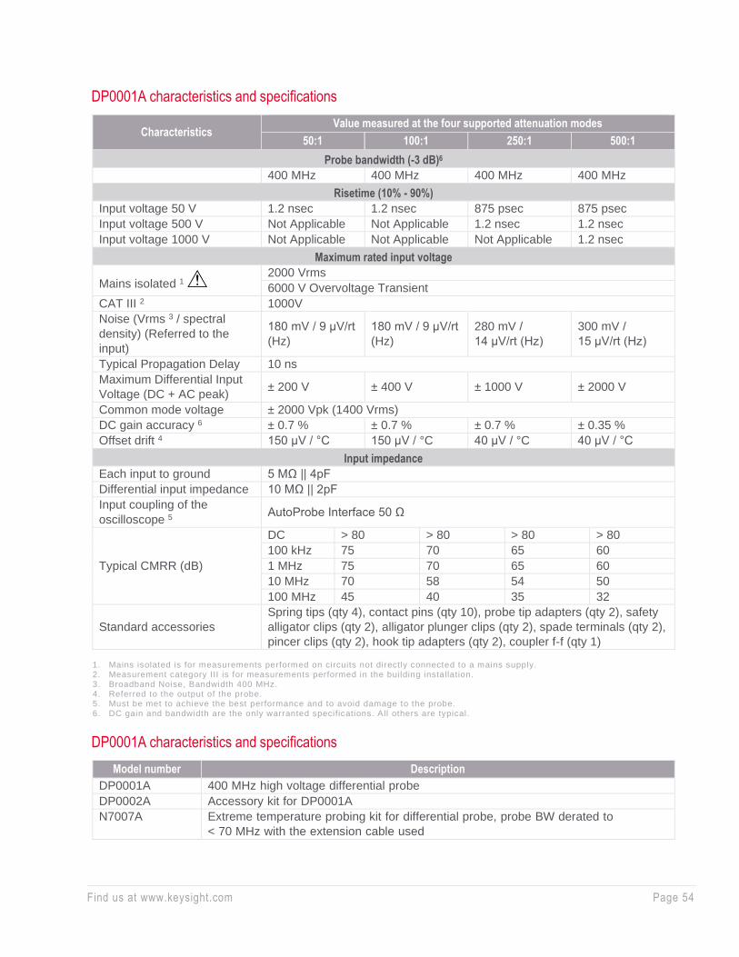
Find us at www.keysight.com Page 54
DP0001A characteristics and specifications
Characteristics Value measured at the four supported attenuation modes
50:1 100:1 250:1 500:1
Probe bandwidth (-3 dB)6
400 MHz 400 MHz 400 MHz 400 MHz
Risetime (10% - 90%)
Input voltage 50 V 1.2 nsec 1.2 nsec 875 psec 875 psec
Input voltage 500 V Not Applicable Not Applicable 1.2 nsec 1.2 nsec
Input voltage 1000 V Not Applicable Not Applicable Not Applicable 1.2 nsec
Maximum rated input voltage
Mains isolated 1 2000 Vrms
6000 V Overvoltage Transient
CAT III 2 1000V
Noise (Vrms 3 / spectral
density) (Referred to the
input)
180 mV / 9 μV/rt
(Hz)
180 mV / 9 μV/rt
(Hz)
280 mV /
14 μV/rt (Hz)
300 mV /
15 μV/rt (Hz)
Typical Propagation Delay 10 ns
Maximum Differential Input
Voltage (DC + AC peak) ± 200 V ± 400 V ± 1000 V ± 2000 V
Common mode voltage ± 2000 Vpk (1400 Vrms)
DC gain accuracy 6 ± 0.7 % ± 0.7 % ± 0.7 % ± 0.35 %
Offset drift 4 150 μV / °C 150 μV / °C 40 μV / °C 40 μV / °C
Input impedance
Each input to ground 5 MΩ || 4pF
Differential input impedance 10 MΩ || 2pF
Input coupling of the
oscilloscope 5 AutoProbe Interface 50 Ω
Typical CMRR (dB)
DC > 80 > 80 > 80 > 80
100 kHz 75 70 65 60
1 MHz 75 70 65 60
10 MHz 70 58 54 50
100 MHz 45 40 35 32
Standard accessories
Spring tips (qty 4), contact pins (qty 10), probe tip adapters (qty 2), safety
alligator clips (qty 2), alligator plunger clips (qty 2), spade terminals (qty 2),
pincer clips (qty 2), hook tip adapters (qty 2), coupler f-f (qty 1)
1. Mains isolated is for measurements performed on circuits not directly connected to a mains supply. 2. Measurement category III is for measurements performed in the building installation. 3. Broadband Noise, Bandwidth 400 MHz. 4. Referred to the output of the probe. 5. Must be met to achieve the best performance and to avoid damage to the probe. 6. DC gain and bandwidth are the only warranted specifications. All others are typical.
DP0001A characteristics and specifications
Model number Description
DP0001A 400 MHz high voltage differential probe
DP0002A Accessory kit for DP0001A
N7007A Extreme temperature probing kit for differential probe, probe BW derated to
< 70 MHz with the extension cable used

Find us at www.keysight.com Page 55
High-Voltage Differential Probes — N2790A/91A/891A
• 25 to 800 MHz bandwidth
• Switchable attenuation
• Measure up to 1,400 V CAT II and 7 kV mains isolated
Oscilloscope users often need to make floating measurements where
neither point of the measurement is at earth ground. Use N2790A, N2791A,
or N2891A high voltage differential probes to make safe and accurate
floating measurements with an oscilloscope. The N2790A, N2791A, and
N2891A high voltage differential probes allow conventional earth-grounded
Keysight oscilloscopes to be used for floating signal measurements.
Each probe offers user-selectable attenuation settings that make it highly
versatile, allowing it to be used for a broad range of applications. The probe
comes with probe tip accessories for use with small and large components
in tight spaces.
The N2791A and N2891A are compatible with any oscilloscope with 1 MΩ
BNC input. The N2791A and N2891A probe power is supplied by the
included 4x AA batteries or the USB host port of the scope, or PC via a
supplied USB power cable. The N2790A is compatible with the Keysight’s
AutoProbe interface where the probe power is supplied by the Keysight
oscilloscope’s probe interface. The N2790A is not compatible with 80000
and 90000 Series oscilloscope.
Most of today’s electronic products must be tested in chambers under
various environmental conditions, including extreme temperatures. The
N7013A is a 70-cm long extreme temperature extension kit compatible with
four of Keysight’s medium- and high- voltage differential active probes
including the N2790A, N2791A, N2792A, and N2818A. With the N7013A
extension kit, the main body of the temperature-sensitive differential active
probe can be placed outside of the environmental chamber, while the 70-cm
long cable pair and connection adapters can be extended into the
environmental chamber under extreme-temperature conditions ranging from
-40 to +85 °C.
N2791A 25 MHz high voltage
differential probe
N2790A measuring a power
supply signal
N2790A 100 MHz high voltage
differential probe
N2790A high voltage differential
probe with N7013A extreme
temperature extension kit
N2891A 70 MHz high voltage
differential probe
N7013A allows the use of differential
probe inside an environmental chamber
for extreme temperature testing
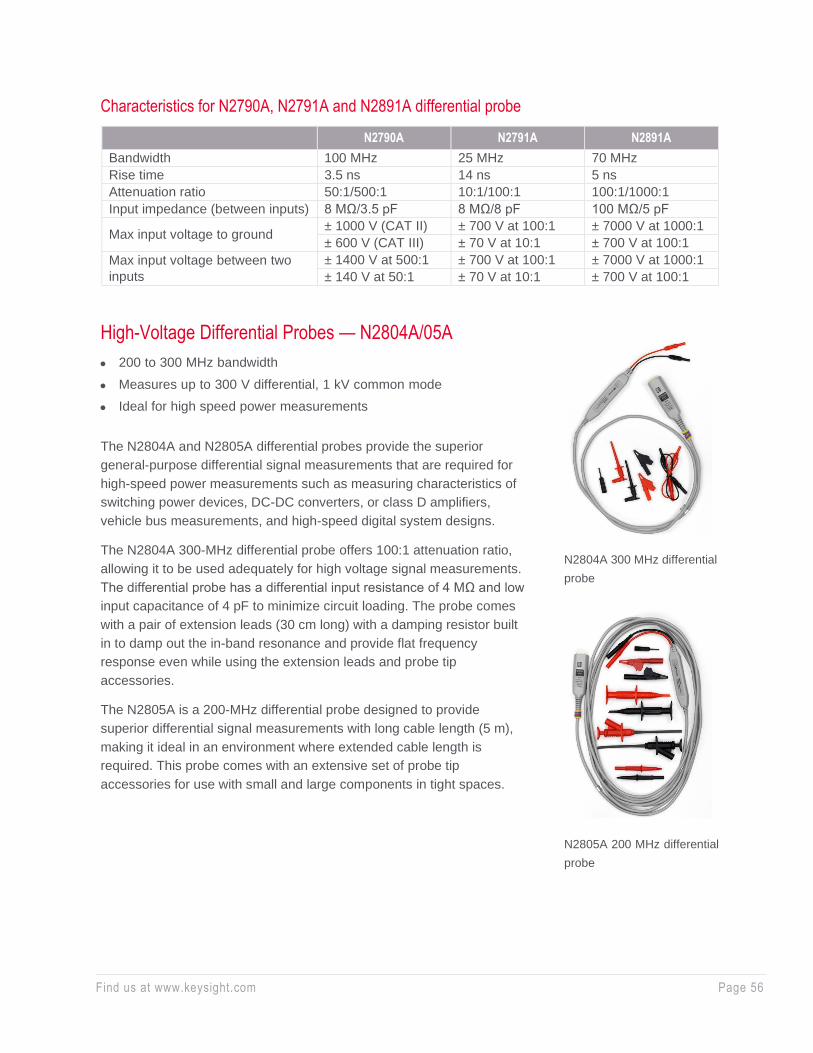
Find us at www.keysight.com Page 56
Characteristics for N2790A, N2791A and N2891A differential probe
N2790A N2791A N2891A
Bandwidth 100 MHz 25 MHz 70 MHz
Rise time 3.5 ns 14 ns 5 ns
Attenuation ratio 50:1/500:1 10:1/100:1 100:1/1000:1
Input impedance (between inputs) 8 MΩ/3.5 pF 8 MΩ/8 pF 100 MΩ/5 pF
Max input voltage to ground ± 1000 V (CAT II) ± 700 V at 100:1 ± 7000 V at 1000:1
± 600 V (CAT III) ± 70 V at 10:1 ± 700 V at 100:1
Max input voltage between two
inputs
± 1400 V at 500:1 ± 700 V at 100:1 ± 7000 V at 1000:1
± 140 V at 50:1 ± 70 V at 10:1 ± 700 V at 100:1
High-Voltage Differential Probes — N2804A/05A
• 200 to 300 MHz bandwidth
• Measures up to 300 V differential, 1 kV common mode
• Ideal for high speed power measurements
The N2804A and N2805A differential probes provide the superior
general-purpose differential signal measurements that are required for
high-speed power measurements such as measuring characteristics of
switching power devices, DC-DC converters, or class D amplifiers,
vehicle bus measurements, and high-speed digital system designs.
The N2804A 300-MHz differential probe offers 100:1 attenuation ratio,
allowing it to be used adequately for high voltage signal measurements.
The differential probe has a differential input resistance of 4 MΩ and low
input capacitance of 4 pF to minimize circuit loading. The probe comes
with a pair of extension leads (30 cm long) with a damping resistor built
in to damp out the in-band resonance and provide flat frequency
response even while using the extension leads and probe tip
accessories.
The N2805A is a 200-MHz differential probe designed to provide
superior differential signal measurements with long cable length (5 m),
making it ideal in an environment where extended cable length is
required. This probe comes with an extensive set of probe tip
accessories for use with small and large components in tight spaces.
N2804A 300 MHz differential
probe
N2805A 200 MHz differential
probe

Find us at www.keysight.com Page 57
N2804A N2805A
Bandwidth
300 MHz (without extension
leads) 200 MHz
120 MHz (with extension leads)
Attenuation ratio 100:1 50:1
DC gain accuracy ± 1% ± 1%
Input impedance (between
inputs) 4 MΩ / 4 pF 4 MΩ / 4 pF
Max input voltage (between
two inputs)
± 300 V (DC+ peak AC) and
± 200 Vrms
± 200 V (DC+ peak AC) and
± 200 Vrms CAT II
Max input voltage
± 300 V (DC+ peak AC) and
± 200 Vrms CAT II
± 500 V (DC+ peak AC) and
± 500 Vrms mains isolated
± 1000 V (DC+ peak AC) and
± 1000 Vrms, mains isolated
± 300 V (DC+ peak AC) and
± 200 Vrms CAT II
Cable length 1.2 m 5 m
Compatible Infiniium
oscilloscopes Infiniium S-Series, 9000, 90000 Series with software 5.2 or higher
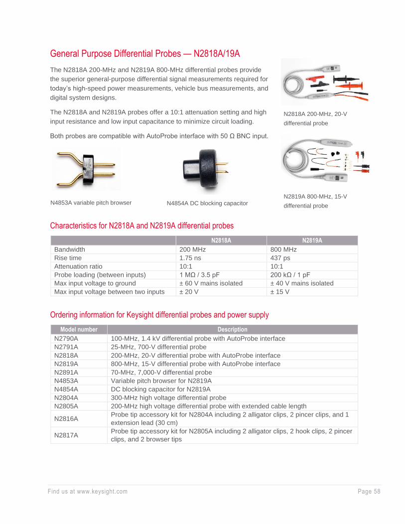
Find us at www.keysight.com Page 58
General Purpose Differential Probes — N2818A/19A
The N2818A 200-MHz and N2819A 800-MHz differential probes provide
the superior general-purpose differential signal measurements required for
today’s high-speed power measurements, vehicle bus measurements, and
digital system designs.
The N2818A and N2819A probes offer a 10:1 attenuation setting and high
input resistance and low input capacitance to minimize circuit loading.
Both probes are compatible with AutoProbe interface with 50 Ω BNC input.
Characteristics for N2818A and N2819A differential probes
N2818A N2819A
Bandwidth 200 MHz 800 MHz
Rise time 1.75 ns 437 ps
Attenuation ratio 10:1 10:1
Probe loading (between inputs) 1 MΩ / 3.5 pF 200 kΩ / 1 pF
Max input voltage to ground ± 60 V mains isolated ± 40 V mains isolated
Max input voltage between two inputs ± 20 V ± 15 V
Ordering information for Keysight differential probes and power supply
Model number Description
N2790A 100-MHz, 1.4 kV differential probe with AutoProbe interface
N2791A 25-MHz, 700-V differential probe
N2818A 200-MHz, 20-V differential probe with AutoProbe interface
N2819A 800-MHz, 15-V differential probe with AutoProbe interface
N2891A 70-MHz, 7,000-V differential probe
N4853A Variable pitch browser for N2819A
N4854A DC blocking capacitor for N2819A
N2804A 300-MHz high voltage differential probe
N2805A 200-MHz high voltage differential probe with extended cable length
N2816A Probe tip accessory kit for N2804A including 2 alligator clips, 2 pincer clips, and 1
extension lead (30 cm)
N2817A Probe tip accessory kit for N2805A including 2 alligator clips, 2 hook clips, 2 pincer
clips, and 2 browser tips
N2818A 200-MHz, 20-V
differential probe
N2819A 800-MHz, 15-V
differential probe N4853A variable pitch browser N4854A DC blocking capacitor
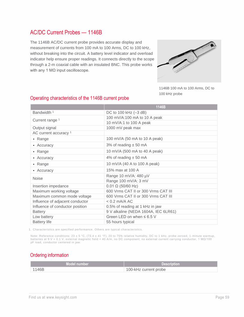
Find us at www.keysight.com Page 59
AC/DC Current Probes — 1146B
The 1146B AC/DC current probe provides accurate display and
measurement of currents from 100 mA to 100 Arms, DC to 100 kHz,
without breaking into the circuit. A battery level indicator and overload
indicator help ensure proper readings. It connects directly to the scope
through a 2-m coaxial cable with an insulated BNC. This probe works
with any 1 MΩ input oscilloscope.
Operating characteristics of the 1146B current probe
1146B
Bandwidth 1 DC to 100 kHz (–3 dB)
Current range 1 100 mV/A:100 mA to 10 A peak
10 mV/A:1 to 100 A peak
Output signal 1000 mV peak max
AC current accuracy 1
• Range 100 mV/A (50 mA to 10 A peak)
• Accuracy 3% of reading ± 50 mA
• Range 10 mV/A (500 mA to 40 A peak)
• Accuracy 4% of reading ± 50 mA
• Range 10 mV/A (40 A to 100 A peak)
• Accuracy 15% max at 100 A
Noise Range 10 mV/A: 480 µV
Range 100 mV/A: 3 mV
Insertion impedance 0.01 Ω (50/60 Hz)
Maximum working voltage 600 Vrms CAT II or 300 Vrms CAT III
Maximum common mode voltage 600 Vrms CAT II or 300 Vrms CAT III
Influence of adjacent conductor < 0.2 mA/A AC
Influence of conductor position 0.5% of reading at 1 kHz in jaw
Battery 9 V alkaline (NEDA 1604A, IEC 6LR61)
Low battery Green LED on when ≤ 6.5 V
Battery life 55 hours typical 1. Characteristics are specified performance. Others are typical characteristics.
Note: Reference conditions: 23 ± 5 °C, (73.4 ± 41 °F), 20 to 75% relative humidity, DC to 1 kHz, probe zeroed, 1 -minute warmup, batteries at 9 V + 0.1 V, external magnetic field < 40 A/m, no DC component, no external current carrying conductor, 1 MΩ/100 pF load, conductor centered in jaw.
Ordering information
Model number Description
1146B 100-kHz current probe
1146B 100 mA to 100 Arms, DC to
100 kHz probe
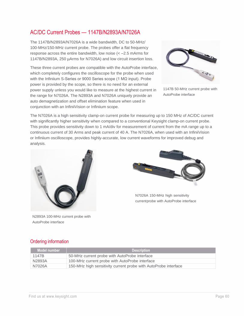
Find us at www.keysight.com Page 60
AC/DC Current Probes — 1147B/N2893A/N7026A
The 1147B/N2893A/N7026A is a wide bandwidth, DC to 50-MHz/
100-MHz/150-MHz current probe. The probes offer a flat frequency
response across the entire bandwidth, low noise (< –2.5 mArms for
1147B/N2893A, 250 µArms for N7026A) and low circuit insertion loss.
These three current probes are compatible with the AutoProbe interface,
which completely configures the oscilloscope for the probe when used
with the Infiniium S-Series or 9000 Series scope (1 MΩ input). Probe
power is provided by the scope, so there is no need for an external
power supply unless you would like to measure at the highest current in
the range for N7026A. The N2893A and N7026A uniquely provide an
auto demagnetization and offset elimination feature when used in
conjunction with an InfiniiVision or Infiniium scope.
The N7026A is a high sensitivity clamp-on current probe for measuring up to 150 MHz of AC/DC current
with significantly higher sensitivity when compared to a conventional Keysight clamp-on current probe.
This probe provides sensitivity down to 1 mA/div for measurement of current from the mA range up to a
continuous current of 30 Arms and peak current of 40 A. The N7026A, when used with an InfiniiVision
or Infiniium oscilloscope, provides highly-accurate, low current waveforms for improved debug and
analysis.
Ordering information
Model number Description
1147B 50-MHz current probe with AutoProbe interface
N2893A 100-MHz current probe with AutoProbe interface
N7026A 150-MHz high sensitivity current probe with AutoProbe interface
1147B 50-MHz current probe with
AutoProbe interface
N2893A 100-MHz current probe with
AutoProbe interface
N7026A 150-MHz high sensitivity
current probe with AutoProbe interface

Find us at www.keysight.com Page 61
Characteristics of the 1147B/N2893A/N7026A current probes
1147B/N2893A N7026A
Bandwidth (–3 dB) DC to 50 MHz (1147B)
DC to 150 MHz DC to 100 MHz (N2893A)
Rise time (calculated, 10% to
90%) 7 nsec (Tr = 0.35/BW) 2.67 nsec (Tr = 0.4/BW)
Maximum current
(continuous) 15 Apeak, 15 ADC, 10 Arms
30 ADC, 30 Arms (with external
power adapter)
5 ADC, 5 Arms (without external
power adapter)
Maximum peak current (non-
continuous) (for pulse-widths
≤ 10 µs)
30 Apeak
40 Apeak (when using external
AC power adapter)
15 Apeak (without using external
power adapter)
Output voltage rate 0.1 V/A 1 V/A and 0.2 V/A, automatically
switched by the oscilloscope
Minimum oscilloscope vertical
scale 10 mA/div 1 mA/div
Amplitude accuracy ± 1% rdg, ± 10 mA (DC or 45 to
66 Hz, rated current)
± 1% rdg. ± 5 mA to 30 Arms
(including calibration scale factor
of oscilloscope measured at DC
or 45 to 66 Hz.)
Noise ≤ 2.5 mArms (for 20 MHz
bandwidth measuring instrument)
≤ 250 µArms (for 20 MHz
bandwidth measuring instrument)
Temperature coefficient for
sensitivity
± 2% or less (within a range of 0 to
40 °C or 32 to 104 °F)
Effect of external magnetic
fields
Equivalent to a maximum of 20 mA (in a DC to 60 Hz, 400 A/m
magnetic field)
Maximum rated power 3 VA (with rated current)
Maximum input voltage 300 V mains isolated
Diameter of measurable
conductors 5 mm dia. (0.2 in dia.)
Probe interface AutoProbe interface (1 MΩ
terminated)
Cable lengths Appox. 1.5 m (59.0 in)
Maximum number of probes
supported 4 2 (9000), 4 (S-Series)
Note: Uniquely with Infiniium MXR/EXR oscilloscopes, the 1147B, N2893A and N7026A provide larger input current ranges going beyond the standard maximum current ranges specified with other Keysight oscilloscopes and the flexibili ty to use the N7026A for measuring high current without using an external AC power adapter at all .
MXR/EXR main channels 1 MXR/EXR secondary channels 2
1147A/B, N2893A
DC: 30 Adc, DC: 15 Adc,
Continuous AC: 30 ARMs, 42 Apeak Continuous AC: 10 ARMs, 15 Apeak
Non-continuous AC: 50 Apk Non-continuous AC: 30 Apk
N7026A
DC: 30 Adc DC: 30 Adc
Continuous AC: 30 ARMs Continuous AC: 30 ARMs
Non-continuous AC: 40 Apk (without
using an external AC power adapter)
Non-continuous AC: 40 Apk (without
using an external AC power adapter)
1. Main channels are channel 1-4 for MXR/EXR 4 and 8 channel models. 2. Secondary channels are channel 5-8 for MXR/EXR 8 channel models.
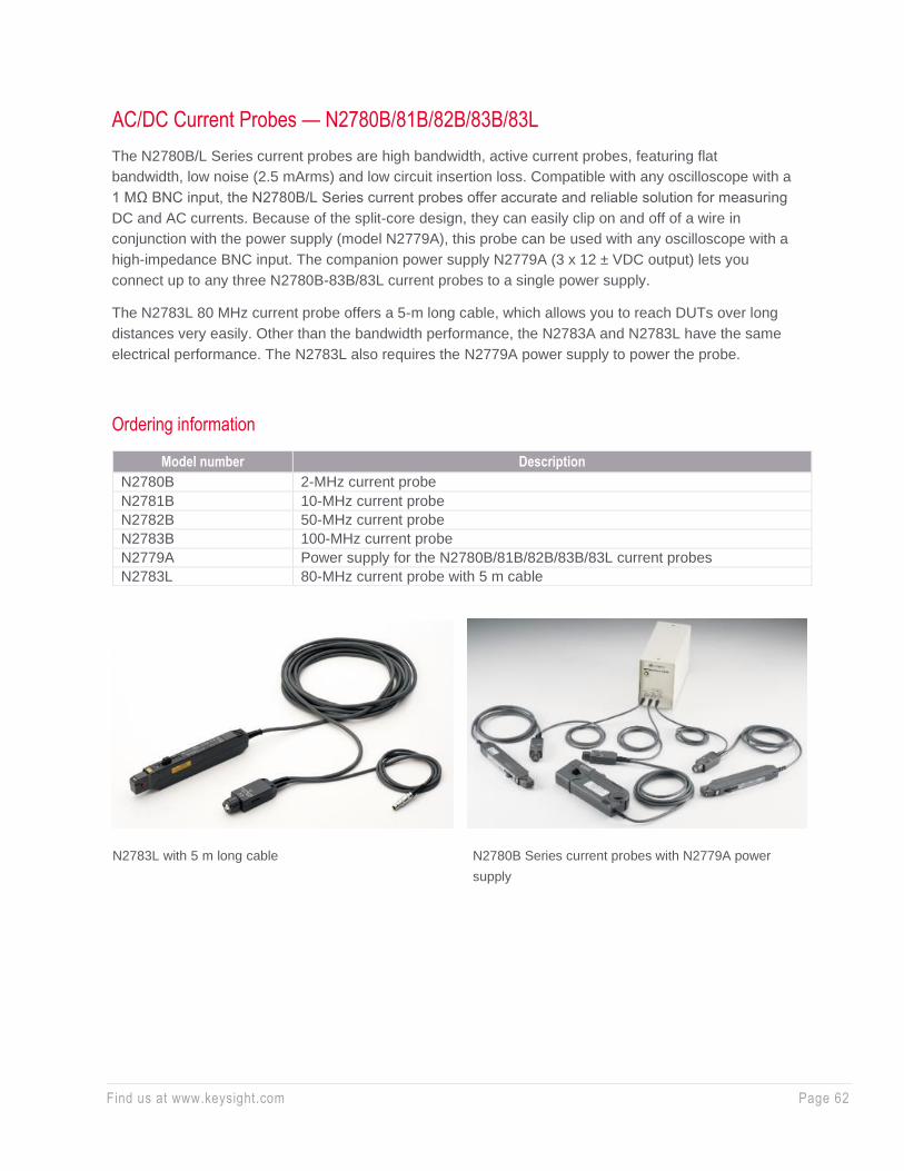
Find us at www.keysight.com Page 62
AC/DC Current Probes — N2780B/81B/82B/83B/83L
The N2780B/L Series current probes are high bandwidth, active current probes, featuring flat
bandwidth, low noise (2.5 mArms) and low circuit insertion loss. Compatible with any oscilloscope with a
1 MΩ BNC input, the N2780B/L Series current probes offer accurate and reliable solution for measuring
DC and AC currents. Because of the split-core design, they can easily clip on and off of a wire in
conjunction with the power supply (model N2779A), this probe can be used with any oscilloscope with a
high-impedance BNC input. The companion power supply N2779A (3 x 12 ± VDC output) lets you
connect up to any three N2780B-83B/83L current probes to a single power supply.
The N2783L 80 MHz current probe offers a 5-m long cable, which allows you to reach DUTs over long
distances very easily. Other than the bandwidth performance, the N2783A and N2783L have the same
electrical performance. The N2783L also requires the N2779A power supply to power the probe.
Ordering information
Model number Description
N2780B 2-MHz current probe
N2781B 10-MHz current probe
N2782B 50-MHz current probe
N2783B 100-MHz current probe
N2779A Power supply for the N2780B/81B/82B/83B/83L current probes
N2783L 80-MHz current probe with 5 m cable
N2783L with 5 m long cable N2780B Series current probes with N2779A power
supply
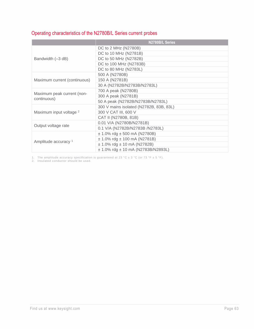
Find us at www.keysight.com Page 63
Operating characteristics of the N2780B/L Series current probes
N2780B/L Series
Bandwidth (–3 dB)
DC to 2 MHz (N2780B)
DC to 10 MHz (N2781B)
DC to 50 MHz (N2782B)
DC to 100 MHz (N2783B)
DC to 80 MHz (N2783L)
Maximum current (continuous)
500 A (N2780B)
150 A (N2781B)
30 A (N2782B/N2783B/N2783L)
Maximum peak current (non-
continuous)
700 A peak (N2780B)
300 A peak (N2781B)
50 A peak (N2782B/N2783B/N2783L)
Maximum input voltage 2
300 V mains isolated (N2782B, 83B, 83L)
300 V CAT III, 600 V
CAT II (N2780B, 81B)
Output voltage rate 0.01 V/A (N2780B/N2781B)
0.1 V/A (N2782B/N2783B /N2783L)
Amplitude accuracy 1
± 1.0% rdg ± 500 mA (N2780B)
± 1.0% rdg ± 100 mA (N2781B)
± 1.0% rdg ± 10 mA (N2782B)
± 1.0% rdg ± 10 mA (N2783B/N2893L)
1. The amplitude accuracy specification is guaranteed at 23 °C ± 3 °C (or 73 °F ± 5 °F). 2. Insulated conductor should be used.
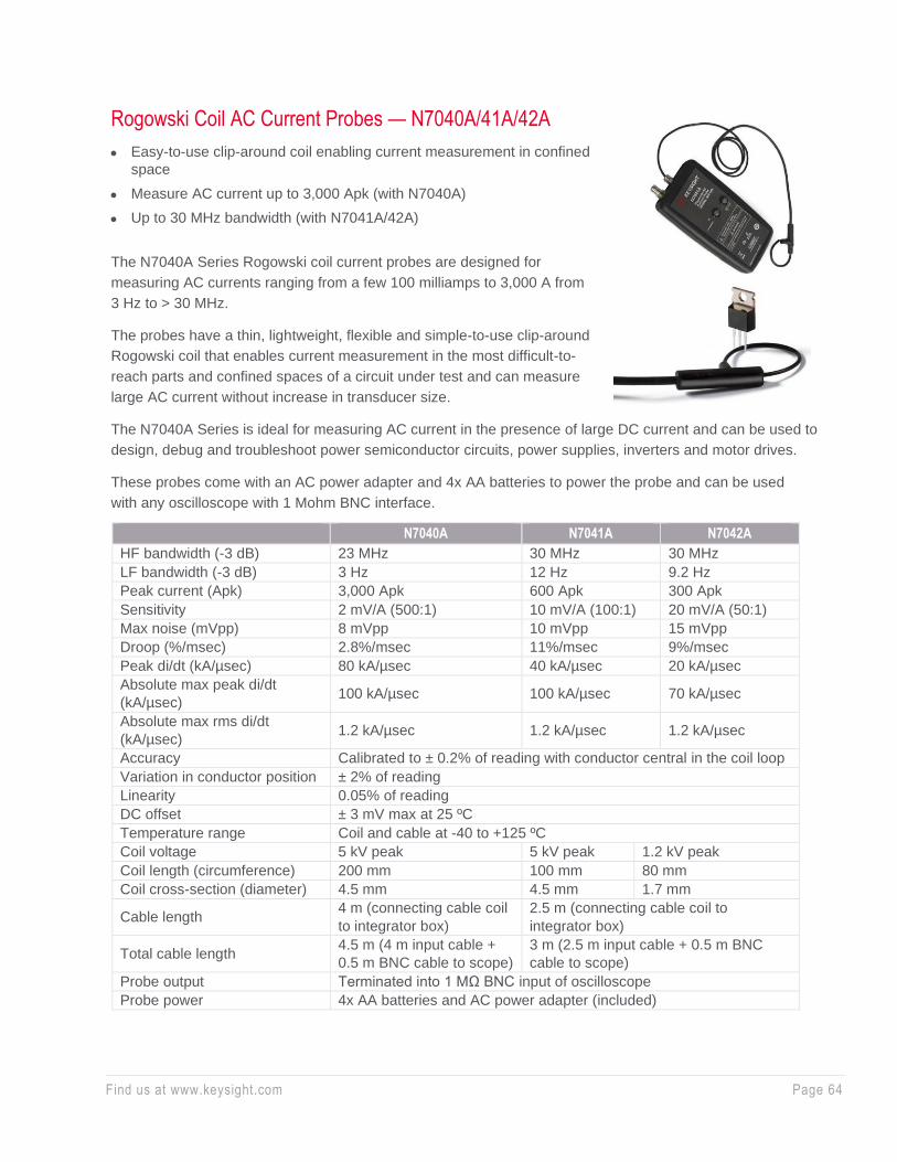
Find us at www.keysight.com Page 64
Rogowski Coil AC Current Probes — N7040A/41A/42A
• Easy-to-use clip-around coil enabling current measurement in confined
space
• Measure AC current up to 3,000 Apk (with N7040A)
• Up to 30 MHz bandwidth (with N7041A/42A)
The N7040A Series Rogowski coil current probes are designed for
measuring AC currents ranging from a few 100 milliamps to 3,000 A from
3 Hz to > 30 MHz.
The probes have a thin, lightweight, flexible and simple-to-use clip-around
Rogowski coil that enables current measurement in the most difficult-to-
reach parts and confined spaces of a circuit under test and can measure
large AC current without increase in transducer size.
The N7040A Series is ideal for measuring AC current in the presence of large DC current and can be used to
design, debug and troubleshoot power semiconductor circuits, power supplies, inverters and motor drives.
These probes come with an AC power adapter and 4x AA batteries to power the probe and can be used
with any oscilloscope with 1 Mohm BNC interface.
N7040A N7041A N7042A
HF bandwidth (-3 dB) 23 MHz 30 MHz 30 MHz
LF bandwidth (-3 dB) 3 Hz 12 Hz 9.2 Hz
Peak current (Apk) 3,000 Apk 600 Apk 300 Apk
Sensitivity 2 mV/A (500:1) 10 mV/A (100:1) 20 mV/A (50:1)
Max noise (mVpp) 8 mVpp 10 mVpp 15 mVpp
Droop (%/msec) 2.8%/msec 11%/msec 9%/msec
Peak di/dt (kA/µsec) 80 kA/µsec 40 kA/µsec 20 kA/µsec
Absolute max peak di/dt
(kA/µsec) 100 kA/µsec 100 kA/µsec 70 kA/µsec
Absolute max rms di/dt
(kA/µsec) 1.2 kA/µsec 1.2 kA/µsec 1.2 kA/µsec
Accuracy Calibrated to ± 0.2% of reading with conductor central in the coil loop
Variation in conductor position ± 2% of reading
Linearity 0.05% of reading
DC offset ± 3 mV max at 25 ºC
Temperature range Coil and cable at -40 to +125 ºC
Coil voltage 5 kV peak 5 kV peak 1.2 kV peak
Coil length (circumference) 200 mm 100 mm 80 mm
Coil cross-section (diameter) 4.5 mm 4.5 mm 1.7 mm
Cable length 4 m (connecting cable coil
to integrator box)
2.5 m (connecting cable coil to
integrator box)
Total cable length 4.5 m (4 m input cable +
0.5 m BNC cable to scope)
3 m (2.5 m input cable + 0.5 m BNC
cable to scope)
Probe output Terminated into 1 MΩ BNC input of oscilloscope
Probe power 4x AA batteries and AC power adapter (included)
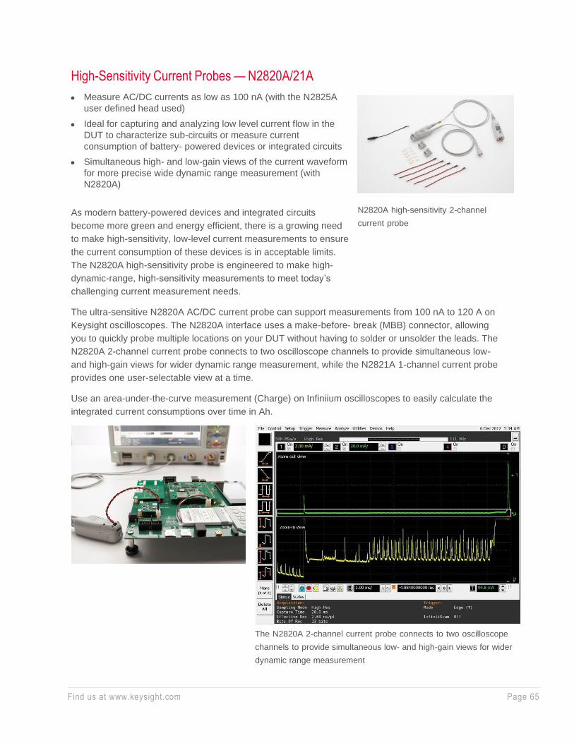
Find us at www.keysight.com Page 65
High-Sensitivity Current Probes — N2820A/21A
• Measure AC/DC currents as low as 100 nA (with the N2825A
user defined head used)
• Ideal for capturing and analyzing low level current flow in the
DUT to characterize sub-circuits or measure current
consumption of battery- powered devices or integrated circuits
• Simultaneous high- and low-gain views of the current waveform
for more precise wide dynamic range measurement (with
N2820A)
As modern battery-powered devices and integrated circuits
become more green and energy efficient, there is a growing need
to make high-sensitivity, low-level current measurements to ensure
the current consumption of these devices is in acceptable limits.
The N2820A high-sensitivity probe is engineered to make high-
dynamic-range, high-sensitivity measurements to meet today’s
challenging current measurement needs.
The ultra-sensitive N2820A AC/DC current probe can support measurements from 100 nA to 120 A on
Keysight oscilloscopes. The N2820A interface uses a make-before- break (MBB) connector, allowing
you to quickly probe multiple locations on your DUT without having to solder or unsolder the leads. The
N2820A 2-channel current probe connects to two oscilloscope channels to provide simultaneous low-
and high-gain views for wider dynamic range measurement, while the N2821A 1-channel current probe
provides one user-selectable view at a time.
Use an area-under-the-curve measurement (Charge) on Infiniium oscilloscopes to easily calculate the
integrated current consumptions over time in Ah.
N2820A high-sensitivity 2-channel
current probe
The N2820A 2-channel current probe connects to two oscilloscope
channels to provide simultaneous low- and high-gain views for wider
dynamic range measurement
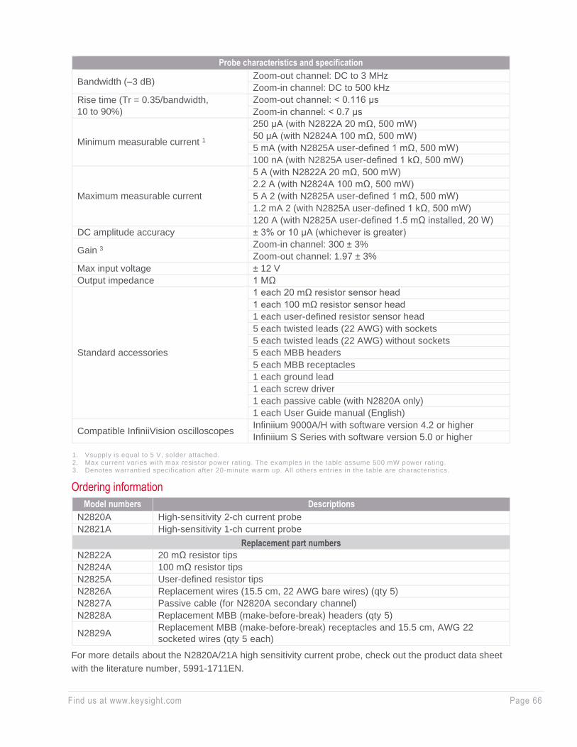
Find us at www.keysight.com Page 66
1. Vsupply is equal to 5 V, solder attached. 2. Max current varies with max resistor power rating. The examples in the table assume 500 mW power rating. 3. Denotes warrantied specification after 20-minute warm up. All others entries in the table are characteristics.
Ordering information
Model numbers Descriptions
N2820A High-sensitivity 2-ch current probe
N2821A High-sensitivity 1-ch current probe
Replacement part numbers
N2822A 20 mΩ resistor tips
N2824A 100 mΩ resistor tips
N2825A User-defined resistor tips
N2826A Replacement wires (15.5 cm, 22 AWG bare wires) (qty 5)
N2827A Passive cable (for N2820A secondary channel)
N2828A Replacement MBB (make-before-break) headers (qty 5)
N2829A Replacement MBB (make-before-break) receptacles and 15.5 cm, AWG 22
socketed wires (qty 5 each)
For more details about the N2820A/21A high sensitivity current probe, check out the product data sheet
with the literature number, 5991-1711EN.
Probe characteristics and specification
Bandwidth (–3 dB) Zoom-out channel: DC to 3 MHz
Zoom-in channel: DC to 500 kHz
Rise time (Tr = 0.35/bandwidth,
10 to 90%)
Zoom-out channel: < 0.116 μs
Zoom-in channel: < 0.7 μs
Minimum measurable current 1
250 μA (with N2822A 20 mΩ, 500 mW)
50 μA (with N2824A 100 mΩ, 500 mW)
5 mA (with N2825A user-defined 1 mΩ, 500 mW)
100 nA (with N2825A user-defined 1 kΩ, 500 mW)
Maximum measurable current
5 A (with N2822A 20 mΩ, 500 mW)
2.2 A (with N2824A 100 mΩ, 500 mW)
5 A 2 (with N2825A user-defined 1 mΩ, 500 mW)
1.2 mA 2 (with N2825A user-defined 1 kΩ, 500 mW)
120 A (with N2825A user-defined 1.5 mΩ installed, 20 W)
DC amplitude accuracy ± 3% or 10 μA (whichever is greater)
Gain 3 Zoom-in channel: 300 ± 3%
Zoom-out channel: 1.97 ± 3%
Max input voltage ± 12 V
Output impedance 1 MΩ
Standard accessories
1 each 20 mΩ resistor sensor head
1 each 100 mΩ resistor sensor head
1 each user-defined resistor sensor head
5 each twisted leads (22 AWG) with sockets
5 each twisted leads (22 AWG) without sockets
5 each MBB headers
5 each MBB receptacles
1 each ground lead
1 each screw driver
1 each passive cable (with N2820A only)
1 each User Guide manual (English)
Compatible InfiniiVision oscilloscopes Infiniium 9000A/H with software version 4.2 or higher
Infiniium S Series with software version 5.0 or higher
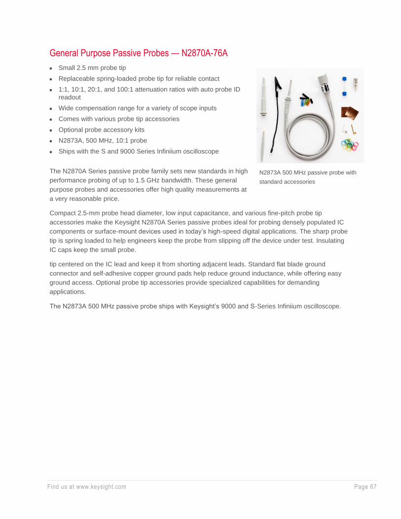
Find us at www.keysight.com Page 67
General Purpose Passive Probes — N2870A-76A
• Small 2.5 mm probe tip
• Replaceable spring-loaded probe tip for reliable contact
• 1:1, 10:1, 20:1, and 100:1 attenuation ratios with auto probe ID
readout
• Wide compensation range for a variety of scope inputs
• Comes with various probe tip accessories
• Optional probe accessory kits
• N2873A, 500 MHz, 10:1 probe
• Ships with the S and 9000 Series Infiniium oscilloscope
The N2870A Series passive probe family sets new standards in high
performance probing of up to 1.5 GHz bandwidth. These general
purpose probes and accessories offer high quality measurements at
a very reasonable price.
Compact 2.5-mm probe head diameter, low input capacitance, and various fine-pitch probe tip
accessories make the Keysight N2870A Series passive probes ideal for probing densely populated IC
components or surface-mount devices used in today’s high-speed digital applications. The sharp probe
tip is spring loaded to help engineers keep the probe from slipping off the device under test. Insulating
IC caps keep the small probe.
tip centered on the IC lead and keep it from shorting adjacent leads. Standard flat blade ground
connector and self-adhesive copper ground pads help reduce ground inductance, while offering easy
ground access. Optional probe tip accessories provide specialized capabilities for demanding
applications.
The N2873A 500 MHz passive probe ships with Keysight’s 9000 and S-Series Infiniium oscilloscope.
N2873A 500 MHz passive probe with
standard accessories
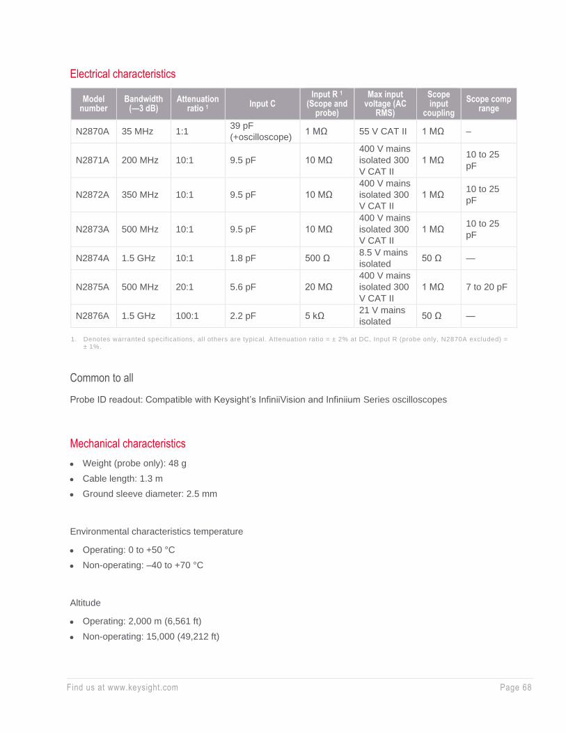
Find us at www.keysight.com Page 68
Electrical characteristics
Model number
Bandwidth (—3 dB)
Attenuation ratio 1
Input C Input R 1
(Scope and probe)
Max input voltage (AC
RMS)
Scope input
coupling
Scope comp range
N2870A 35 MHz 1:1 39 pF
(+oscilloscope) 1 MΩ 55 V CAT II 1 MΩ –
N2871A 200 MHz 10:1 9.5 pF 10 MΩ
400 V mains
isolated 300
V CAT II
1 MΩ 10 to 25
pF
N2872A 350 MHz 10:1 9.5 pF 10 MΩ
400 V mains
isolated 300
V CAT II
1 MΩ 10 to 25
pF
N2873A 500 MHz 10:1 9.5 pF 10 MΩ
400 V mains
isolated 300
V CAT II
1 MΩ 10 to 25
pF
N2874A 1.5 GHz 10:1 1.8 pF 500 Ω 8.5 V mains
isolated 50 Ω —
N2875A 500 MHz 20:1 5.6 pF 20 MΩ
400 V mains
isolated 300
V CAT II
1 MΩ 7 to 20 pF
N2876A 1.5 GHz 100:1 2.2 pF 5 kΩ 21 V mains
isolated 50 Ω —
1. Denotes warranted specifications, all others are typical. Attenuation ratio = ± 2% at DC, Input R (probe only, N2870A excluded) =
± 1%.
Common to all
Probe ID readout: Compatible with Keysight’s InfiniiVision and Infiniium Series oscilloscopes
Mechanical characteristics
• Weight (probe only): 48 g
• Cable length: 1.3 m
• Ground sleeve diameter: 2.5 mm
Environmental characteristics temperature
• Operating: 0 to +50 °C
• Non-operating: –40 to +70 °C
Altitude
• Operating: 2,000 m (6,561 ft)
• Non-operating: 15,000 (49,212 ft)
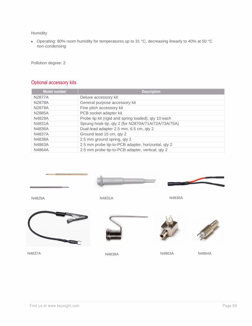
Find us at www.keysight.com Page 69
Humidity
• Operating: 80% room humidity for temperatures up to 31 °C, decreasing linearly to 40% at 50 °C
non-condensing
Pollution degree: 2
Optional accessory kits
Model number Description
N2877A Deluxe accessory kit
N2878A General purpose accessory kit
N2879A Fine pitch accessory kit
N2885A PCB socket adapter kit
N4829A Probe tip kit (rigid and spring loaded), qty 10 each
N4831A Sprung hook tip, qty 2 (for N2870A/71A/72A/73A/75A)
N4836A Dual-lead adapter 2.5 mm, 6.5 cm, qty 2
N4837A Ground lead 15 cm, qty 2
N4838A 2.5 mm ground spring, qty 2
N4863A 2.5 mm probe tip-to-PCB adapter, horizontal, qty 2
N4864A 2.5 mm probe tip-to-PCB adapter, vertical, qty 2
N4829A N4831A N4836A
N4863A N4838A N4837A N4864A
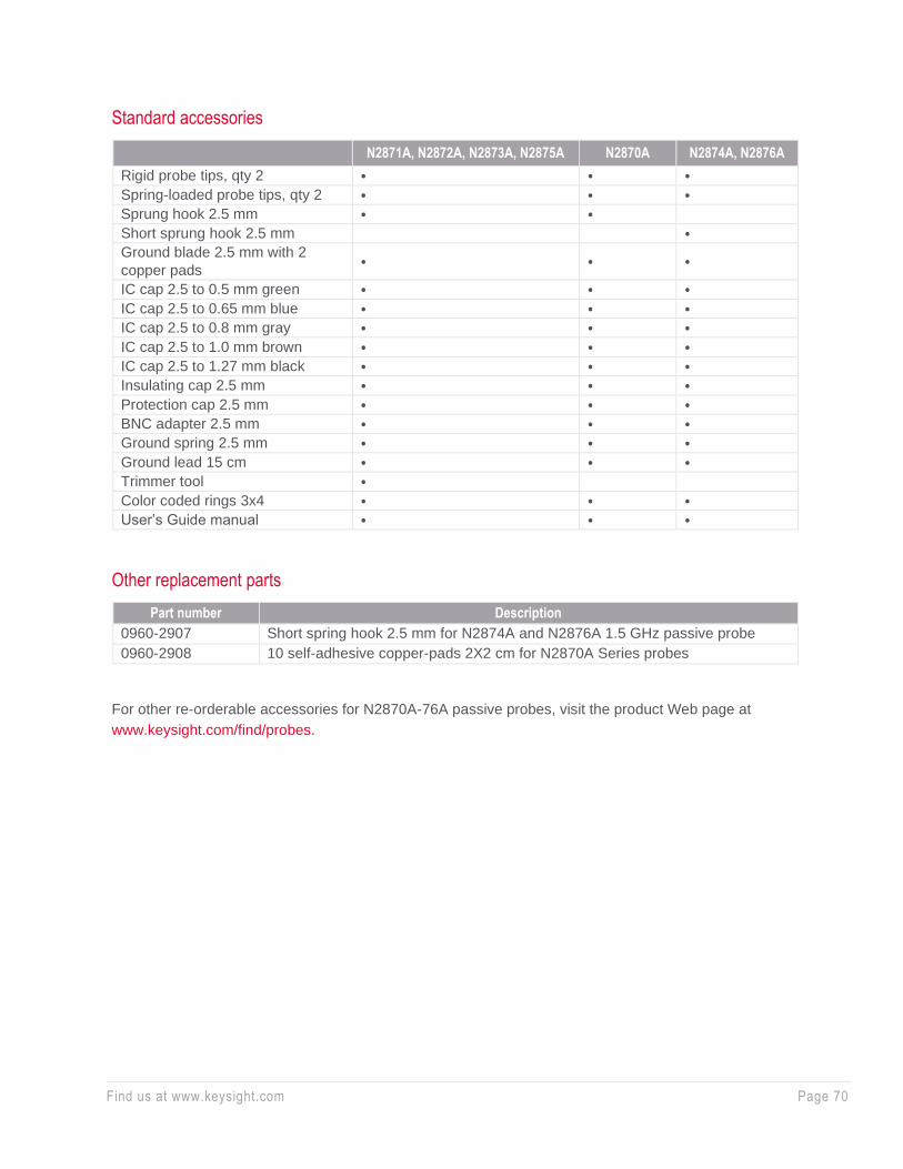
Find us at www.keysight.com Page 70
Standard accessories
N2871A, N2872A, N2873A, N2875A N2870A N2874A, N2876A
Rigid probe tips, qty 2 ⦁ ⦁ ⦁
Spring-loaded probe tips, qty 2 ⦁ ⦁ ⦁
Sprung hook 2.5 mm ⦁ ⦁
Short sprung hook 2.5 mm ⦁
Ground blade 2.5 mm with 2
copper pads ⦁ ⦁ ⦁
IC cap 2.5 to 0.5 mm green ⦁ ⦁ ⦁
IC cap 2.5 to 0.65 mm blue ⦁ ⦁ ⦁
IC cap 2.5 to 0.8 mm gray ⦁ ⦁ ⦁
IC cap 2.5 to 1.0 mm brown ⦁ ⦁ ⦁
IC cap 2.5 to 1.27 mm black ⦁ ⦁ ⦁
Insulating cap 2.5 mm ⦁ ⦁ ⦁
Protection cap 2.5 mm ⦁ ⦁ ⦁
BNC adapter 2.5 mm ⦁ ⦁ ⦁
Ground spring 2.5 mm ⦁ ⦁ ⦁
Ground lead 15 cm ⦁ ⦁ ⦁
Trimmer tool ⦁
Color coded rings 3x4 ⦁ ⦁ ⦁
User’s Guide manual ⦁ ⦁ ⦁
Other replacement parts
Part number Description
0960-2907 Short spring hook 2.5 mm for N2874A and N2876A 1.5 GHz passive probe
0960-2908 10 self-adhesive copper-pads 2X2 cm for N2870A Series probes
For other re-orderable accessories for N2870A-76A passive probes, visit the product Web page at
www.keysight.com/find/probes.

Find us at www.keysight.com Page 71
Extreme Temperature Passive Probe — N7007A
Features and specifications
• Wide operating temperature range of –40 to +85 °C for extreme temperature
environmental chamber testing
• 400 MHz bandwidth (–3 dB)
• High impedance (10 MΩ at DC) input
• Wide input range: 1 kV CAT II, 600V CAT III
• Includes hook tip adapters (x2), ground leads (x2), and spring ground tip (x1)
The N7007A 400 MHz passive probe is a low-cost, high impedance passive
probe with rugged probe tips for environmental chamber testing from –40 to
+85 °C range. Its large input impedance (10 MΩ at DC) and wide input voltage
range (1,000 Vdc + peak AC CATII) makes the probe ideal for a broad range
of general purpose extreme temperature applications.
Key characteristics
N7007A
Bandwidth 400 MHz (with spring ground), 70 MHz (with ground lead)
Attenuation ratio 10:1
Input impedance (at DC) 10 MΩ//15.5 pF (when terminated into 1 MΩ)
Oscilloscope compensation range 6 to 18 pF
Operating temperature range -40 to +85 °C
Operating humidity range < 90% at 40 °C non-condensing
Cable length 2 m
Max input range 1 kV CAT II, 600V CAT III
Ordering information
N7007A 10:1 400 MHz extreme temperature passive probe
N7006A Spring ground for N7007A
N7008A Hook tip adapter for N7007A
N7009A Ground lead for N7007A
N7006A spring ground
N7007A passive probe
N7008A hook tip adapter N7009A ground lead
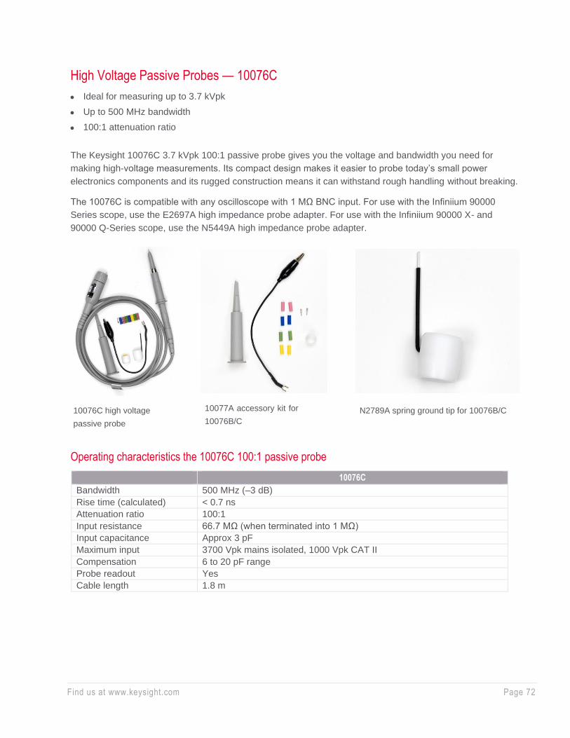
Find us at www.keysight.com Page 72
High Voltage Passive Probes — 10076C
• Ideal for measuring up to 3.7 kVpk
• Up to 500 MHz bandwidth
• 100:1 attenuation ratio
The Keysight 10076C 3.7 kVpk 100:1 passive probe gives you the voltage and bandwidth you need for
making high-voltage measurements. Its compact design makes it easier to probe today’s small power
electronics components and its rugged construction means it can withstand rough handling without breaking.
The 10076C is compatible with any oscilloscope with 1 MΩ BNC input. For use with the Infiniium 90000
Series scope, use the E2697A high impedance probe adapter. For use with the Infiniium 90000 X- and
90000 Q-Series scope, use the N5449A high impedance probe adapter.
Operating characteristics the 10076C 100:1 passive probe
10076C
Bandwidth 500 MHz (–3 dB)
Rise time (calculated) < 0.7 ns
Attenuation ratio 100:1
Input resistance 66.7 MΩ (when terminated into 1 MΩ)
Input capacitance Approx 3 pF
Maximum input 3700 Vpk mains isolated, 1000 Vpk CAT II
Compensation 6 to 20 pF range
Probe readout Yes
Cable length 1.8 m
10076C high voltage
passive probe
N2789A spring ground tip for 10076B/C 10077A accessory kit for
10076B/C

Find us at www.keysight.com Page 73
Ordering information
Model number Description Quantity
10076C
High-voltage probe: includes one retractable hook tip, one ground-
bayonet, one IC probing tip, one alligator ground lead, and a
compensation screwdriver
1
10077A Accessory kit for 10076B/C including one retractable hook pin, one
ground lead, one insulation cap, two measuring pin, and eight ID tags 1
N2789A Spring ground tip for 10076B/C 1
10076C derating curve
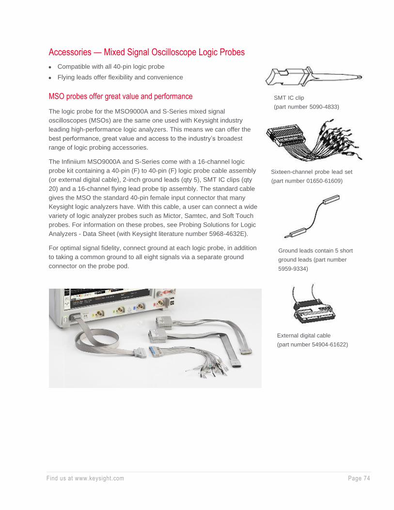
Find us at www.keysight.com Page 74
Accessories — Mixed Signal Oscilloscope Logic Probes
• Compatible with all 40-pin logic probe
• Flying leads offer flexibility and convenience
MSO probes offer great value and performance
The logic probe for the MSO9000A and S-Series mixed signal
oscilloscopes (MSOs) are the same one used with Keysight industry
leading high-performance logic analyzers. This means we can offer the
best performance, great value and access to the industry’s broadest
range of logic probing accessories.
The Infiniium MSO9000A and S-Series come with a 16-channel logic
probe kit containing a 40-pin (F) to 40-pin (F) logic probe cable assembly
(or external digital cable), 2-inch ground leads (qty 5), SMT IC clips (qty
20) and a 16-channel flying lead probe tip assembly. The standard cable
gives the MSO the standard 40-pin female input connector that many
Keysight logic analyzers have. With this cable, a user can connect a wide
variety of logic analyzer probes such as Mictor, Samtec, and Soft Touch
probes. For information on these probes, see Probing Solutions for Logic
Analyzers - Data Sheet (with Keysight literature number 5968-4632E).
For optimal signal fidelity, connect ground at each logic probe, in addition
to taking a common ground to all eight signals via a separate ground
connector on the probe pod.
SMT IC clip
(part number 5090-4833)
Sixteen-channel probe lead set
(part number 01650-61609)
Ground leads contain 5 short
ground leads (part number
5959-9334)
External digital cable
(part number 54904-61622)

Find us at www.keysight.com Page 75
Characteristics for Keysight Infiniium MSO logic probe kit
Analog bandwidth of cable and flying leads 400 MHz
Input resistance 100 kΩ ± 2%
Input capacitance 8 pF at the tip
Kit parts supplied (Order individual part numbers as shown right.)
16-channel probe set leads x1
Ground leads x5
SMT IC clips x20
External digital cable x1
The 9000 and S Series MSO digital channels were architected to be compatible with a wide variety of
probing accessories developed over 20 years for logic analyzers. There is a good chance that the logic
analyzer accessories you already own work with your MSO. With the standard 40-pin cable that comes
with your MSO, the MSO accepts numerous logic analyzer accessories including:
• E5346A 34-channel Mictor connector probe
• E5385A 34-channel Samtec connector
• E5383B 16-channel flying lead set 01650-63203 16-channel termination adapter (also available as a
bundle of both the termination adapter and the 40-pin cable with PN 10085-68701)
• E5404A 34-channel soft touch pro connectorless probe
• E5394A 34-channel soft touch connectorless probe
• E5396A 16-channel soft touch connectorless probe
• Any other accessory that connects to a logic analyzer via a 40-pin cable
For logic accessories of greater channel width than MSO digital channels (> 16 channels), there are two
use models.
• Route up to 16 signals to the probe and do not use the additional probe channels.
• Route up to 32 signals to the probe and measure half of them at a time. Simply plug the 40-pin cable to
the other side of the probe to see the other half of the signals.

Find us at www.keysight.com Page 76
E5385A 34-channel Samtec connector probe
E5396A 16-ch (half size) soft touch
connector less probe
E5346A 34-channel Mictor connector probe
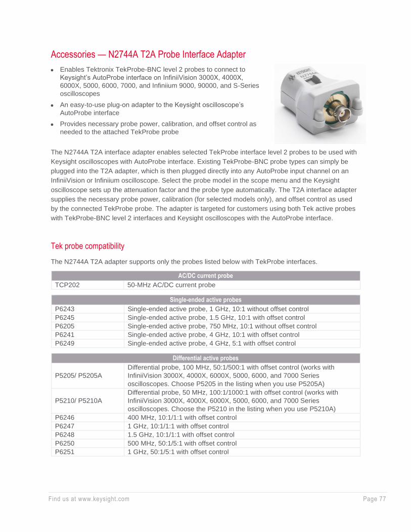
Find us at www.keysight.com Page 77
Accessories — N2744A T2A Probe Interface Adapter
• Enables Tektronix TekProbe-BNC level 2 probes to connect to
Keysight’s AutoProbe interface on InfiniiVision 3000X, 4000X,
6000X, 5000, 6000, 7000, and Infiniium 9000, 90000, and S-Series
oscilloscopes
• An easy-to-use plug-on adapter to the Keysight oscilloscope’s
AutoProbe interface
• Provides necessary probe power, calibration, and offset control as
needed to the attached TekProbe probe
The N2744A T2A interface adapter enables selected TekProbe interface level 2 probes to be used with
Keysight oscilloscopes with AutoProbe interface. Existing TekProbe-BNC probe types can simply be
plugged into the T2A adapter, which is then plugged directly into any AutoProbe input channel on an
InfiniiVision or Infiniium oscilloscope. Select the probe model in the scope menu and the Keysight
oscilloscope sets up the attenuation factor and the probe type automatically. The T2A interface adapter
supplies the necessary probe power, calibration (for selected models only), and offset control as used
by the connected TekProbe probe. The adapter is targeted for customers using both Tek active probes
with TekProbe-BNC level 2 interfaces and Keysight oscilloscopes with the AutoProbe interface.
Tek probe compatibility
The N2744A T2A adapter supports only the probes listed below with TekProbe interfaces.
AC/DC current probe
TCP202 50-MHz AC/DC current probe
Single-ended active probes
P6243 Single-ended active probe, 1 GHz, 10:1 without offset control
P6245 Single-ended active probe, 1.5 GHz, 10:1 with offset control
P6205 Single-ended active probe, 750 MHz, 10:1 without offset control
P6241 Single-ended active probe, 4 GHz, 10:1 with offset control
P6249 Single-ended active probe, 4 GHz, 5:1 with offset control
Differential active probes
P5205/ P5205A
Differential probe, 100 MHz, 50:1/500:1 with offset control (works with
InfiniiVision 3000X, 4000X, 6000X, 5000, 6000, and 7000 Series
oscilloscopes. Choose P5205 in the listing when you use P5205A)
P5210/ P5210A
Differential probe, 50 MHz, 100:1/1000:1 with offset control (works with
InfiniiVision 3000X, 4000X, 6000X, 5000, 6000, and 7000 Series
oscilloscopes. Choose the P5210 in the listing when you use P5210A)
P6246 400 MHz, 10:1/1:1 with offset control
P6247 1 GHz, 10:1/1:1 with offset control
P6248 1.5 GHz, 10:1/1:1 with offset control
P6250 500 MHz, 50:1/5:1 with offset control
P6251 1 GHz, 50:1/5:1 with offset control
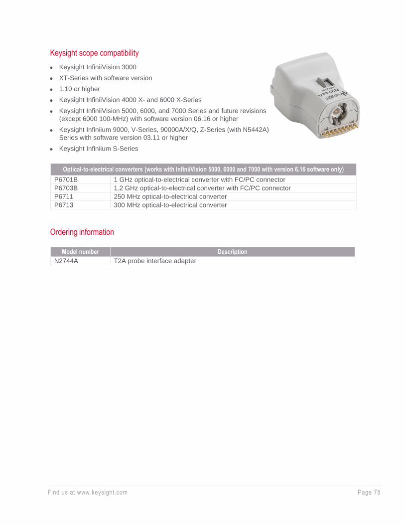
Find us at www.keysight.com Page 78
Keysight scope compatibility
• Keysight InfiniiVision 3000
• XT-Series with software version
• 1.10 or higher
• Keysight InfiniiVision 4000 X- and 6000 X-Series
• Keysight InfiniiVision 5000, 6000, and 7000 Series and future revisions
(except 6000 100-MHz) with software version 06.16 or higher
• Keysight Infiniium 9000, V-Series, 90000A/X/Q, Z-Series (with N5442A)
Series with software version 03.11 or higher
• Keysight Infiniium S-Series
Ordering information
Optical-to-electrical converters (works with InfiniiVision 5000, 6000 and 7000 with version 6.16 software only)
P6701B 1 GHz optical-to-electrical converter with FC/PC connector
P6703B 1.2 GHz optical-to-electrical converter with FC/PC connector
P6711 250 MHz optical-to-electrical converter
P6713 300 MHz optical-to-electrical converter
Model number Description
N2744A T2A probe interface adapter

Find us at www.keysight.com Page 79
Accessories — N2784A/85A/86A/87A Probe Positioners
• Easy-to-manipulate probe arms for hands-free browsing
• One- or two-articulated arms with stable high-mass base (N2784A
and N2785A)
• Quick and stable X-Y positioning (N2786A)
• Stable 3D probe positioning for hard-to-reach XYZ access
• Compatible with most scope probes
• Applications: Hands-free browsing for electronic components on PC
board
The N2784A and N2785A probe positioners provide quick and stable
X-Y positioning for PC boards and devices that require hands-free
probing.
Unlike other probe positioners that require multiple adjustments to lock
the probe holder into position, the N2784A and N2785A need only the
“lift and drop” motion to put the probe in place. The weight stabilization
technique used in these probe holders keeps constant pressure at the
probing point so the probe tip stays in position even when the target
board is bumped.
The N2786A is a low cost, easy-to-use X-Y axis probe holder for
general purpose probing applications. The two-legged positioner is
designed to be easy to use—, the positioner itself has no controls to
position it in place.
The N2787A is a 3D probe positioner with a flexible, articulating arm
that can be quickly positioned in a variety of configurations.
For more information about Keysight’s probe positioners, refer to
literature number 5989-9131EN.
Ordering information
Product number Description
N2784A 1 1-arm probe positioner
N2785A 1 2-arm probe positioner
N2786A 2-leg probe positioner
N2787A 3D probe positioner
1. Includes 3x magnifying glass, arm strap, cable tie, probe rest, and manual.
N2786A 2-leg probe positioner
N2787A 3D probe positioner
N2784A one-arm probe positioner
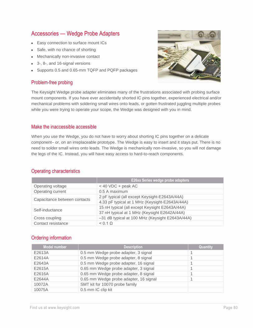
Find us at www.keysight.com Page 80
Accessories — Wedge Probe Adapters
• Easy connection to surface mount ICs
• Safe, with no chance of shorting
• Mechanically non-invasive contact
• 3-, 8-, and 16-signal versions
• Supports 0.5 and 0.65-mm TQFP and PQFP packages
Problem-free probing
The Keysight Wedge probe adapter eliminates many of the frustrations associated with probing surface
mount components. If you have ever accidentally shorted IC pins together, experienced electrical and/or
mechanical problems with soldering small wires onto leads, or gotten frustrated juggling multiple probes
while you were trying to operate your scope, the Wedge was designed with you in mind.
Make the inaccessible accessible
When you use the Wedge, you do not have to worry about shorting IC pins together on a delicate
component– or, on an irreplaceable prototype. The Wedge is easy to insert and it stays put. There is no
need to solder small wires onto leads. The Wedge is mechanically non-invasive, so you will not damage
the legs of the IC. Instead, you will have easy access to hard-to-reach components.
Operating characteristics
E26xx Series wedge probe adapters
Operating voltage < 40 VDC + peak AC
Operating current 0.5 A maximum
Capacitance between contacts 2 pF typical (all except Keysight-E2643A/44A)
4.33 pF typical at 1 MHz (Keysight-E2643A/44A)
Self-inductance 15 nH typical (all except Keysight E2643A/44A)
37 nH typical at 1 MHz (Keysight E2642A/44A)
Cross coupling –31 dB typical at 100 MHz (Keysight E2643A/44A)
Contact resistance < 0.1 Ω
Ordering information
Model number Description Quantity
E2613A 0.5 mm Wedge probe adapter, 3 signal 1
E2614A 0.5 mm Wedge probe adapter, 8 signal 1
E2643A 0.5 mm Wedge probe adapter, 16 signal 1
E2615A 0.65 mm Wedge probe adapter, 3 signal 1
E2616A 0.65 mm Wedge probe adapter, 8 signal 1
E2644A 0.65 mm Wedge probe adapter, 16 signal 1
10072A SMT kit for 10070 probe family
10075A 0.5 mm IC clip kit

Find us at www.keysight.com Page 81
Electrical reliability
The Wedge makes two contact points with each leg of the IC. This redundant physical connection
increases the electrical reliability of the connection. Also the Wedge’s low capacitance and inductance
provides superior performance to many other alternatives.
The Wedge probe adapter connects directly to 1145A/1155A active probes and the dual lead adapter
provided with the 1160A-65A passive probe family and N2877A/N2879A accessory kits for use with
N287xA Series passive probes.
IC clip kits
As an inexpensive solution for probing fine-pitch ICs, the 10072A SMT kit includes 10 IC clips and 2
dual-lead adapters that connect the clips directly to 10070-family probes.
The 10075A 0.5-mm IC clip kit is ideal for connecting to IC’s as fine as 0.5 mm. The clip body allows
many clips to be mounted side-by-side. The kit includes four 0.5-mm IC clips and two dual-lead
adapters that connect the IC clips directly to 10070-family probes.
Accessories — Fine Pitch and PC Board Accessories
0.5 mm IC clips
• Extremely small size
• Thin body for mounting multiple clips side-by side
• Connection to PQFP and SOIC SMT packages from 0.5 to
0.8 mm (0.020 in. to 0.032 in.) lead pitch
The 0.5 mm IC clips connect directly to the Infiniium MSO logic
probe flying leads, N2870A-76A or 1160A-65A passive probe
with dual lead adapter, and 1007x passive probe with optional
10072A or 10075A that contain the dual lead adapter.
Maximum input voltage is +40 V.
Operating characteristics
0.5 IC Clips
Length 31.75 mm (1.25 in)
Tip diameter 0.75 mm (0.029 in)
Pin diameter 0.75 mm (0.029 in)
Ordering information
Part number Description Quantity
10467-68701 0.5 mm IC clips 4
Extremely small-sized clips for probing
PQFP and SOIC SMT packages.
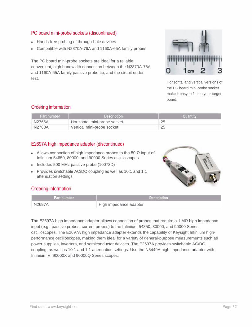
Find us at www.keysight.com Page 82
PC board mini-probe sockets (discontinued)
• Hands-free probing of through-hole devices
• Compatible with N2870A-76A and 1160A-65A family probes
The PC board mini-probe sockets are ideal for a reliable,
convenient, high bandwidth connection between the N2870A-76A
and 1160A-65A family passive probe tip, and the circuit under
test.
Ordering information
Part number Description Quantity
N2766A Horizontal mini-probe socket 25
N2768A Vertical mini-probe socket 25
E2697A high impedance adapter (discontinued)
• Allows connection of high impedance probes to the 50 Ω input of
Infiniium 54850, 80000, and 90000 Series oscilloscopes
• Includes 500 MHz passive probe (10073D)
• Provides switchable AC/DC coupling as well as 10:1 and 1:1
attenuation settings
Ordering information
Part number Description
N2697A High impedance adapter
The E2697A high impedance adapter allows connection of probes that require a 1 MΩ high impedance
input (e.g., passive probes, current probes) to the Infiniium 54850, 80000, and 90000 Series
oscilloscopes. The E2697A high impedance adapter extends the capability of Keysight Infiniium high-
performance oscilloscopes, making them ideal for a variety of general-purpose measurements such as
power supplies, inverters, and semiconductor devices. The E2697A provides switchable AC/DC
coupling, as well as 10:1 and 1:1 attenuation settings. Use the N5449A high impedance adapter with
Infiniium V, 90000X and 90000Q Series scopes.
Horizontal and vertical versions of
the PC board mini-probe socket
make it easy to fit into your target
board.
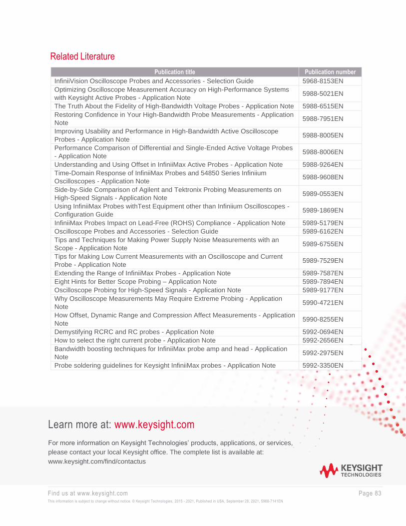
Find us at www.keysight.com Page 83 This information is subject to change without notice. © Keysight Technologies, 2015 - 2021, Published in USA, September 28, 2021, 5968-7141EN
Learn more at: www.keysight.com
For more information on Keysight Technologies’ products, applications, or services,
please contact your local Keysight office. The complete list is available at:
www.keysight.com/find/contactus
Related Literature
Publication title Publication number
InfiniiVision Oscilloscope Probes and Accessories - Selection Guide 5968-8153EN
Optimizing Oscilloscope Measurement Accuracy on High-Performance Systems
with Keysight Active Probes - Application Note 5988-5021EN
The Truth About the Fidelity of High-Bandwidth Voltage Probes - Application Note 5988-6515EN
Restoring Confidence in Your High-Bandwidth Probe Measurements - Application
Note 5988-7951EN
Improving Usability and Performance in High-Bandwidth Active Oscilloscope
Probes - Application Note 5988-8005EN
Performance Comparison of Differential and Single-Ended Active Voltage Probes
- Application Note 5988-8006EN
Understanding and Using Offset in InfiniiMax Active Probes - Application Note 5988-9264EN
Time-Domain Response of InfiniiMax Probes and 54850 Series Infiniium
Oscilloscopes - Application Note 5988-9608EN
Side-by-Side Comparison of Agilent and Tektronix Probing Measurements on
High-Speed Signals - Application Note 5989-0553EN
Using InfiniiMax Probes withTest Equipment other than Infiniium Oscilloscopes -
Configuration Guide 5989-1869EN
InfiniiMax Probes Impact on Lead-Free (ROHS) Compliance - Application Note 5989-5179EN
Oscilloscope Probes and Accessories - Selection Guide 5989-6162EN
Tips and Techniques for Making Power Supply Noise Measurements with an
Scope - Application Note 5989-6755EN
Tips for Making Low Current Measurements with an Oscilloscope and Current
Probe - Application Note 5989-7529EN
Extending the Range of InfiniiMax Probes - Application Note 5989-7587EN
Eight Hints for Better Scope Probing – Application Note 5989-7894EN
Oscilloscope Probing for High-Speed Signals - Application Note 5989-9177EN
Why Oscilloscope Measurements May Require Extreme Probing - Application
Note 5990-4721EN
How Offset, Dynamic Range and Compression Affect Measurements - Application
Note 5990-8255EN
Demystifying RCRC and RC probes - Application Note 5992-0694EN
How to select the right current probe - Application Note 5992-2656EN
Bandwidth boosting techniques for InfiniiMax probe amp and head - Application
Note 5992-2975EN
Probe soldering guidelines for Keysight InfiniiMax probes - Application Note 5992-3350EN