Embed Size (px)
Citation preview

Department of InformaticsNetworks and Distributed Systems (ND) group
INF 3190Wireless Communications
Özgü [email protected]
Simula Research Laboratory

2
Outline
• Brief history of wireless• What is wireless communication?• Bottom-down approach
– Physical layer : how can we transmit signals in air?– Link layer : multiple access – Wireless impact higher layers?
• Wireless Systems– Wifi– Mobile Broadband Networks

3
Wireless History
• James C Maxwell ( 1831- 1879) laying the theoretical
foundation for EM fields with his famous equations
• Heinrich Hertz (1857- 1894 ) was the first to demonstrate
the wave character of electrical transmission through
space (1886). (Note Today the unit Hz reminds us of this
discovery).
• Radio invented in the 1880s by Marconi
• The 1st radio broadcast took place in 1906 when
Reginald A Fessenden transmitted voice and music for
Christmas.

4
Wireless History cont…
• In 1915 , the first wireless voice transmission was set up between New York and San Francisco
• In 1926, the first telephone in a train was available on the Berlin – Hamburg line
• 1928 was the year of many field trials for TV broadcasting. John L Baird ( 1888 – 1946 ) transmitted TV across Atlantic and demonstrated color TV

5
Wireless History cont …• 1946, Public Mobile in 25 US cities, high power transmitter
on large tower. Covers distance of 50 Km. Push to talk.
• 1982: Groupe Spéciale Mobile was launched to developstandards for pan-European mobile network
• GSM now stands for Global System for Mobile Communications
• 1992 Official commercial launch of GSM in Europe

6
Wireless History cont …• 1997 - Wireless LANs• 2000 - Bluetooth with 1Mbit/s specification, single cell.
Later work on 10Mbit/s spec with multi cell capability • In 2005 mobile phone subscribers exceed fixed phone
subscriber. • In 2012 the number of subscriber reaches 1 million.• In 2014, the number of mobile devices grow to a total of
7.4 billion, exceeding the world’s population.
• Today: 5G, convergence of technologies to support billions of connected devices.
7
Outline
• Brief history of wireless• What is wireless communication?• Bottom-down approach
– Physical layer : how can we transmit signals in air?– Link layer : multiple access – Wireless impact higher layers?
• Wireless Systems– Mobile Broadband Networks– Wifi

8
Why Wireless?• Freedom from wires
– No cost of installing the wires– Not deal with bunches of wires running around
• Global coverage– where wired communication is not feasible or costly
e.g. rural areas, battle field and outer space.• Stay Connected
– Any where any time, even under mobility• Flexibility
– Connect to multiple devices simultaneously

9
• Transmitting voice and data using electromagnetic waves in open space
• Electromagnetic waves • Travel at speed of light (c = 3x10⁸ m/s)• Has a frequency (f) and wavelength (l)
» c = f x l
What is Wireless Communication?

10
Wireless Link Characteristics
• decreased signal strength: radio signal attenuates (lose
signal strength) as it propagates through matter (path
loss)
• Higher frequencies will attenuate FASTER
• Higher frequencies also don’t penetrate objects as well
• interference from other sources: standardized wireless
frequencies shared by other devices (e.g., phone);
devices (motors) interfere as well
• multipath propagation: radio signal reflects off
objects/ground, reaching destination at slightly different
times
…. make communication across (even a point to point) wireless
link much more “difficult”

11
Electromagnetic Spectrum
104 102 100 10-2 10-4 10-6 10-8 10-10 10-12 10-14 10-16
104 106 108 1010 1012 1014 1016 1018 1020 1022 1024
IR UV X-Rays Cosmic Rays
RadioSpectrum
3MHz ==100m300MHz ==1m 30GHz ==1cm
< 30 KHz VLF30-300KHz LF 300KHz – 3MHz MF3 MHz – 30MHz HF 30MHz – 300MHz VHF300 MHz – 3GHz UHF3-30GHz SHF> 30 GHz EHF
Microwave
Visible light

12
Electromagnetic Spectrum
12

13
Outline
• Brief history of wireless• What is wireless communication?• Bottom-down approach
– Physical layer : how can we transmit signals in air?– Link layer : multiple access – Wireless impact higher layers?
• Wireless Systems– Mobile Broadband Networks– Wifi

14
Block diagram of radio transmission• Information (e.g. sound) is converted by a transducer (e.g.
a microphone) to an electrical signal• This signal is used to modulate a radio wave sent from a
transmitter. • A receiver intercepts the radio wave and extracts the
information-bearing electronic signal, which is converted back using another transducer such as a speaker.

15
What is modulation?• Modulation = Adding information to a carrier signal• The sine wave on which the characteristics of the information signal are modulated is called a carrier signal

16
Preliminaries
Carrier signal:

17
Types of Modulation
• ANALOG MODULATION: If the variation in the parameter of the carrier is continuous in accordance to the input analog signal the modulation technique is termed as analog modulation scheme
• DIGITAL MODULATION: If the variation in the parameter of the carrier is discrete then it is termed as digital modulation technique

18
ANALOG MODULATION
Amplitude Modulation: Signal shapes the amplitude of the carrier
Frequency Modulation: Signal shapes the frequency of the carrier

19
DIGITAL MODULATION TECHNIQUES

20
Outline
• Brief history of wireless• What is wireless communication?• Bottom-down approach
– Physical layer : how can we transmit signals in air?– Link layer : multiple access – Wireless impact higher layers?
• Wireless Systems– Mobile Broadband Networks– Wifi

21
Multiplexing (MUX) / Multiple Access (MA)• Transmission of several data flows (logical connections) over one
medium– Realize individual “connections“, normally with deterministic
properties (throughput, delay)– Terminology: ??M („“.. Multiplexing“) or ??MA (“.. Multiple Access“)
• Also:Transmission of one data flow (logical connection) over several media– (increase performance and/or reliability)
High PerformanceConnection
several connections with less performance / quality

22
Time Division Multiple Access (TDMA)• Each user is allowed to transmit
only within specified time intervals (Time Slots). Different users transmit in different Time Slots.
• When users transmit, they occupy the whole frequency bandwidth (separation among users is performed in the time domain).
• Commonly used in GSM together with frequency hopping

23
Frequency Division Multiple Access (FDMA)
• Each user transmits with no limitations in time, but using only a portion of the whole available frequency bandwidth
• Different users are separated in the frequency domain
• FDMA can be used for both digital and analog signals
• Very common in satellite communications
q The major disadvantage of FDMA is the relativelyexpensive and complicated bandpass filters required.

24
FDMA in time domain

25
Code Division Multiple Access (CDMA)• unique “code” assigned to each user; i.e., code set
partitioning– all users share same frequency, but each user has own “chipping” sequence (i.e., code) to encode data
– allows multiple users to “coexist” and transmit simultaneously with minimal interference
• Chip sequences are orthogonal to ensurereconstructability:
– seq. 1: x = (x1, .. xn), seq. 2: y = (y1, .. yn) å xi yi = 0
– Common choice: Walsh sequence
• encoded signal = (original data) X (chipping sequence)
• decoding: inner-product of encoded signal and chipping sequence

26
CDMA encode/decode
slot 1 slot 0
d1 = -1
1 1 1 1
1- 1- 1- 1-
Zi,m= di.cmd0 = 1
1 1 1 1
1- 1- 1- 1-
1 1 1 1
1- 1- 1- 1-
1 1 11
1-1- 1- 1-
slot 0channeloutput
slot 1channeloutput
channel output Zi,m
sendercode
databits
slot 1 slot 0
d1 = -1d0 = 1
1 1 1 1
1- 1- 1- 1-
1 1 1 1
1- 1- 1- 1-
1 1 1 1
1- 1- 1- 1-
1 1 11
1-1- 1- 1-
slot 0channeloutput
slot 1channeloutputreceiver
code
receivedinput
Di = S Zi,m.cmm=1
M
M

27
CDMA: two-sender interference
using same code as sender 1, receiver recovers sender 1’s original data from summed channel data!
Sender 1
Sender 2
channel sums together transmissions by sender 1 and 2

28
Orthogonal Frequency Division Multiple Access (OFDMA)
• The carriers are chosen such that they are orthogonal to one another

29
Orthogonality Principle
• Real Function space
0)()(
)cos()()sin()(
0)()(
)cos()()sin()(
21
2
1
=
==
=
==
ò
ò
+
+
dttftf
nwtNtfmwtMtf
dttftf
wtBtfwtAtf
n
T
m
n
m
T
t
t
t
t
Here mw and nw are called m-th and n-th harmonics of w respectively

30
Summary: FDMA,TDMA, CDMA and OFDMA1G/TACS 2G/GSM
3G 4G/LTE and Wimax

31
Outline
• Brief history of wireless• What is wireless communication?• Bottom-down approach
– Physical layer : how can we transmit signals in air?– Link layer : multiple access – Wireless impact higher layers?
• Wireless Systems– Mobile Broadband Networks– Wifi

32
Wireless: impact on higher layers• logically, impact should be minimal …
– best effort service model remains unchanged – TCP and UDP can (and do) run over wireless, mobile
• … but performance-wise:– packet loss/delay due to bit-errors (discarded packets,
delays for link-layer retransmissions), and handoff– TCP interprets loss as congestion, will decrease
congestion window un-necessarily– delay impairments for real-time traffic– limited bandwidth of wireless links

33
Outline
• Brief history of wireless• What is wireless communication?• Bottom-down approach
– Physical layer : how can we transmit signals in air?– Link layer : multiple access – Wireless impact higher layers?
• Wireless Systems– Mobile Broadband Networks– Wifi

34
• Mobile networks (e.g. 3G/4G)– Underpins a lot of vital operations of the modern
society• Extended coverage• Mobility• Security
Mobile Broadband (MBB) Networks

35
Macro View
• Building Blocks of MBB Networks– Radio Access Network– Core Network

36
Closer look to LTE
UTRAN: UMTS Terrestrial Radio Access Network

37
eNodeB is responsible for:• User and mobility management
• Dynamic Air Interface Resource Allocation (Scheduler)
• Interference management among base stations
• Ensuring QoS (service-subscriber)
Inter eNodeB interface• Handover management
– If target eNodeB is known and reachable -> eNodeBscommunicate (neighbor relations through mobile devices)
– If not, over the core network
• Inter-cell interference coordination
– Mobile devices report noise levels to their serving eNodeB
– Contact with neighboring eNodeB to mitigate the problem

38
Closer look to LTE

39
Home Subscriber Service (HSS)
• Central database that contains information about all the network operators subscribers
• Contains the subscription related information (subscriber profiles)
• Performs authentication and authorization of the user
• Provides information about the subscriber’s location and IP

40
Mobility Management Entity (MME)• Network Access Control: MME manages authentication and
authorization for the UE.
• Radio Resource Management: MME works with the HSS and the RAN to decide the appropriate radio resource management strategy (RRM) that can be UE-specific.
• Mobility Management: One of the most complex functions MME performs. Providing seamless inter-working has multiple use cases such as Inter-eNB and Inter-RAT, among others.
• Roaming Management: MME supports outbound and inbound roaming subscribers from other LTE/EPC systems and legacy networks.
• UE Reachability: MME manages communication with the UE and HSS to provide UE reachability and activity-related information.
• Lawful Intercept: Since MME manages the control plane of the network, MME can provide the whereabouts of a UE to a law enforcement monitoring facility.

41
Serving Gateway (S-GW)• Acts like a high level router
– Routes and forwards data packets from eNodeBs to PDN-GW• Mobility anchor for the user plane during inter-eNB handovers • Anchor for mobility between LTE and other 3GPP
technologies
Packet Data Network Gateway (PDN-GW)• Point of contact with the outside world
– Connects the UE to external packet data networks – point of exit and entry of traffic for the UE
• The PDN-GW performs policy enforcement, packet filtering and screening per user, charging support, lawful Interception

42
Policy and Charging Rule Function (PCRF)
How a certain packet is delivered to a certain user considering the QoS and charging?• QoS: Differentiation of subscribers and services• Charge subscribers based on their volume of usage
of high-bandwidth applications • Charge extra for QoS guarantees• Limit app usage while a user is roaming • Lower the bandwidth of wireless subscribers using
heavy-bandwidth apps during peak usage times.
43
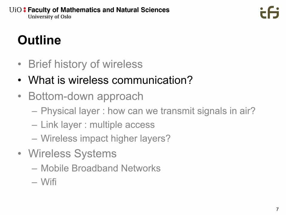
A Simplified Data Flow with 4G…(1/2)
MME
S-GW
Packet Data Networke..g Internet
SGi
S11
S1u
eNodeB
MS
S1
HSS DNS
Attach request..
Get info for this subscriber
Herewith the info
I am attached to the network and
want to browse to www.google.com
What is the S-GW IP Address ?What is the P-GW IP Address ?
Herewith the IP Addresses
Create Session Request with IP Address of S-GW and P-GW
Create Session Request response (Accept)
P-GW
Create Session Request with IP Address of P-GW
Create Session Request response (Accept)
Create Session Request response (Accept)
S5/S8
Reference : TS 29.281TS 23.401TS 29.274
1
2
3
4
5
6
7
8
9
10
11

44
A Simplified Data Flow with 4G… (2/2)
MME
S-GW
Packet Data Networke..g Internet
SGi
S11
S1u
eNodeB
MS
S1
HSS DNS
I am attached to the network and
want to browse to www.google.com
P-GWS5/S8
Reference : TS 29.281TS 23.401TS 29.274
11 12
Internet DNS
13

45
Free roaming in Europe

46
Roaming Infrastructure

47
Future: Different use cases and applications for 5G Networks

48
Different requirements for 5G applications and services

49
End-to-end 5G connectivity

50
Outline
• Brief history of wireless• What is wireless communication?• Bottom-down approach
– Physical layer : how can we transmit signals in air?– Link layer : multiple access – Wireless impact higher layers?
• Wireless Systems– Mobile Broadband Networks– Wifi

51
Wireless LAN Architecture
v wireless host communicates with access points (AP)
v The owner of the AP becomes the operator
v Basic Service Set (BSS) in infrastructure mode contains:§ wireless hosts§ access point (AP): base
station§ ad hoc mode: hosts only
BSS 1
BSS 2
Internet
hub, switchor router

52
IEEE 802.11 Wireless LAN802.11b
– 2.4-5 GHz unlicensed spectrum
– up to 11 Mbps
802.11a– 5-6 GHz range– up to 54 Mbps
802.11g– 2.4-5 GHz range– up to 54 Mbps
802.11n: multiple antennas– 2.4-5 GHz range– up to 200 Mbps

53
Wireless network characteristics (1)Multiple wireless senders and receivers create
additional problems (beyond multiple access):
A B C
A�s signalstrength
space
C�s signalstrength
Signal attenuation:v B, A hear each otherv B, C hear each otherv A, C can not hear each other
interfering at B

54
Wireless network characteristics (2)Multiple wireless senders and receivers create
additional problems (beyond multiple access):
AB
C
Hidden terminal problemv B, A hear each otherv B, C hear each otherv A, C can not hear each other
means A, C unaware of their interference at B
Exposed terminal problemv C wants to send D, A wants to
send Bv When A transmits to B, C
waitsv But D is outside of the range
of A, so the wait is unnecessary

55
• Listen (CS) Before Talk (LBT):– channel idle: transmit entire frame– channel busy: defer transmission
• 1-Persistent CSMA: retry immediately when channel becomes idle• P-Persistent CSMA: retry immediately with probability p when channel
becomes idle• Non-persistent CSMA: retry after random interval
• Human analogy: don’t interrupt others!– Politicians are sometimes 1-Persistent…
• Collisions– sender 1 may not immediately see 2’s transmission (propagation delay)– entire frame transmision time wasted
What happens if two senders do this?
Carrier Sense Multiple Access (CSMA)

57
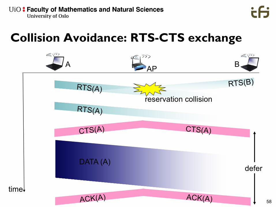
Avoiding collisions
Idea: allow sender to “reserve” channel rather than random access of data frames: avoid collisions of long data frames
• sender first transmits small request-to-send (RTS) packets to BS using CSMA– RTSs may still collide with each other (but they’re short)
• BS broadcasts clear-to-send CTS in response to RTS• CTS heard by all nodes
– sender transmits data frame– other stations defer transmissions
avoid data frame collisions completely using small reservation packets!
58
Collision Avoidance: RTS-CTS exchange
APA B
time
RTS(A) RTS(B)
RTS(A)
CTS(A) CTS(A)
DATA (A)
ACK(A) ACK(A)
reservation collision
defer

59
OTHER WIRELESS NETWORKS

60
Satellite Networks
• More than 500 satellites have been launched, servicing radio, television and telephony.
• Universal Coverage, limited data rate, costly• Applications:
– Broadcasting, telephony and backup to terresterial– Military: providing robust and sophisticated secure
communications network– Mission critical services– Autonomous driving and Unmanned Aerial Vehicle– Tele-medicine

61
Wireless Sensor Networks (WSNs)
• Based on 802.15.4– Some devices: ZigBee (802.15.4 PHY+MAC + layers 3 / 7 )– uses CSMA/CA– Many devices can run TinyOS or Contiki OSes
• Specific scenarios – alarm based systems, regular measurements, ... => specific improvements possible– e.g. static topology, regular updates: can do special routing; can
put nodes to sleep when they don’t communicate– transport: sometimes per-hop reliability– often: one static sink => “funneling effect” of traffic going “up the
tree”, earlier battery depletion of nodes near the sink– Solution: mobile sink (e.g. radio controlled helicopter)

62
Mobile Ad Hoc Networks (MANETs)
• Mobile devices, also acting as routers• Memory and CPU restrictions• Flexible environment, changing topology• Not too many realistic usage scenarios
– When do you not have a base station but want to connect anyway?
• Military battlefield was a common example scenario –is it the only real use case?
– Better to incorporate base stations and consider the (somewhat less mobile) network formed by the heterogeneous equipment connected in this way
• Wireless Mesh Network (WMN)

63
Cognitive Radio
• Spectrum utilization depends strongly on time and place– Could do better than always use the same allocated frequencies
• Idea: let unlicensed (“secondary”) users access licensed bands without interfering with licensed (“primary”) users– Ideally, access a database which maintains a common view of
who uses which spectrum– Many issues
(e.g. security,incentives forcooperating, ..)


![INF 3190 Wireless Communications · 5 Wireless History cont … • Invention of FM in 1933 by Edwin H Armstrong [ 1890 - 1954 ] . • 1946, Public Mobile in 25 US cities, high power](https://img.pdfslide.us/doc/110x75/604fb1c4b19b4619ae4a1b64/inf-3190-wireless-communications-5-wireless-history-cont-a-invention-of-fm-in.jpg)