Embed Size (px)
Citation preview

EIO0000000268 07/2010
EIO
0000
0002
68 .0
1
www.schneider-electric.com
Magelis Compact 12’’Industrial PCsUser Manual
07/2010

The information provided in this documentation contains general descriptions and/or technical characteristics of the performance of the products contained herein. This documentation is not intended as a substitute for and is not to be used for determining suitability or reliability of these products for specific user applications. It is the duty of any such user or integrator to perform the appropriate and complete risk analysis, evaluation and testing of the products with respect to the relevant specific application or use thereof. Neither Schneider Electric nor any of its affiliates or subsidiaries shall be responsible or liable for misuse of the information contained herein. If you have any suggestions for improvements or amendments or have found errors in this publication, please notify us.
No part of this document may be reproduced in any form or by any means, electronic or mechanical, including photocopying, without express written permission of Schneider Electric.
All pertinent state, regional, and local safety regulations must be observed when installing and using this product. For reasons of safety and to help ensure compliance with documented system data, only the manufacturer should perform repairs to components.
When devices are used for applications with technical safety requirements, the relevant instructions must be followed.
Failure to use Schneider Electric software or approved software with our hardware products may result in injury, harm, or improper operating results.
Failure to observe this information can result in injury or equipment damage.
© 2010 Schneider Electric. All rights reserved.
2 EIO0000000268 07/2010
Table of Contents
Safety Information . . . . . . . . . . . . . . . . . . . . . . . . . . . . . . 5About the Book . . . . . . . . . . . . . . . . . . . . . . . . . . . . . . . . . 7
Part I General Overview . . . . . . . . . . . . . . . . . . . . . . . . . . . . 13Chapter 1 Important Information . . . . . . . . . . . . . . . . . . . . . . . . . . . 15
Federal Communications Commission Radio Frequency Interference Statement - For U.S.A. . . . . . . . . . . . . . . . . . . . . . . . . . . . . . . . . . . . . . . . 16Qualified Personnel . . . . . . . . . . . . . . . . . . . . . . . . . . . . . . . . . . . . . . . . . . 17Safety Information for the UK . . . . . . . . . . . . . . . . . . . . . . . . . . . . . . . . . . 18Certifications and Standards . . . . . . . . . . . . . . . . . . . . . . . . . . . . . . . . . . . 20European (CE) Compliance . . . . . . . . . . . . . . . . . . . . . . . . . . . . . . . . . . . 21
Chapter 2 Physical Overview . . . . . . . . . . . . . . . . . . . . . . . . . . . . . . 23Package Contents . . . . . . . . . . . . . . . . . . . . . . . . . . . . . . . . . . . . . . . . . . . 24Compact Unit Description . . . . . . . . . . . . . . . . . . . . . . . . . . . . . . . . . . . . . 26Interface Specification . . . . . . . . . . . . . . . . . . . . . . . . . . . . . . . . . . . . . . . . 29
Chapter 3 Characteristics . . . . . . . . . . . . . . . . . . . . . . . . . . . . . . . . . 31Characteristics of the Compact 12’’. . . . . . . . . . . . . . . . . . . . . . . . . . . . . . 32Flash Disk Characteristics. . . . . . . . . . . . . . . . . . . . . . . . . . . . . . . . . . . . . 34Environmental Characteristics. . . . . . . . . . . . . . . . . . . . . . . . . . . . . . . . . . 35
Chapter 4 Dimensions/Assembly . . . . . . . . . . . . . . . . . . . . . . . . . . . 37Dimensions . . . . . . . . . . . . . . . . . . . . . . . . . . . . . . . . . . . . . . . . . . . . . . . . 38Panel Mounting . . . . . . . . . . . . . . . . . . . . . . . . . . . . . . . . . . . . . . . . . . . . . 41Preparing to Install the 12’’ Compact . . . . . . . . . . . . . . . . . . . . . . . . . . . . 43
Part II Implementation. . . . . . . . . . . . . . . . . . . . . . . . . . . . . . 49Chapter 5 Getting Started . . . . . . . . . . . . . . . . . . . . . . . . . . . . . . . . . 51
First Power-up. . . . . . . . . . . . . . . . . . . . . . . . . . . . . . . . . . . . . . . . . . . . . . 51Chapter 6 Main Power Connection . . . . . . . . . . . . . . . . . . . . . . . . . . 53
Grounding . . . . . . . . . . . . . . . . . . . . . . . . . . . . . . . . . . . . . . . . . . . . . . . . . 54Connecting the AC Power Cord . . . . . . . . . . . . . . . . . . . . . . . . . . . . . . . . 57
Chapter 7 Configuration of the BIOS . . . . . . . . . . . . . . . . . . . . . . . . 59Accessing the BIOS . . . . . . . . . . . . . . . . . . . . . . . . . . . . . . . . . . . . . . . . . 59
EIO0000000268 07/2010 3

Chapter 8 Hardware Modifications . . . . . . . . . . . . . . . . . . . . . . . . . . 63Before Modifications . . . . . . . . . . . . . . . . . . . . . . . . . . . . . . . . . . . . . . . . 64Installing a Larger RAM Chip. . . . . . . . . . . . . . . . . . . . . . . . . . . . . . . . . . 66Expansion Board (PCI) Installation . . . . . . . . . . . . . . . . . . . . . . . . . . . . . 68PCMCIA Card Installation . . . . . . . . . . . . . . . . . . . . . . . . . . . . . . . . . . . . 70Compact Flash (CF) Card Installation and Removal . . . . . . . . . . . . . . . . 73USB Holder Attachment/Removal . . . . . . . . . . . . . . . . . . . . . . . . . . . . . . 76Hard Disk Drive (HDD) Unit Installation . . . . . . . . . . . . . . . . . . . . . . . . . . 79
Part III Installation . . . . . . . . . . . . . . . . . . . . . . . . . . . . . . . . . 83Chapter 9 Connections to PLCs. . . . . . . . . . . . . . . . . . . . . . . . . . . . . 85
Connection to PLCs. . . . . . . . . . . . . . . . . . . . . . . . . . . . . . . . . . . . . . . . . 85Chapter 10 System Monitoring. . . . . . . . . . . . . . . . . . . . . . . . . . . . . . . 89
System Monitor Overview . . . . . . . . . . . . . . . . . . . . . . . . . . . . . . . . . . . . 90System Monitor Property . . . . . . . . . . . . . . . . . . . . . . . . . . . . . . . . . . . . . 97System Monitor Interface. . . . . . . . . . . . . . . . . . . . . . . . . . . . . . . . . . . . . 102
Chapter 11 Maintenance . . . . . . . . . . . . . . . . . . . . . . . . . . . . . . . . . . . . 109Reinstallation Procedure . . . . . . . . . . . . . . . . . . . . . . . . . . . . . . . . . . . . . 110Regular Cleaning and Maintenance. . . . . . . . . . . . . . . . . . . . . . . . . . . . . 113
Chapter 12 Troubleshooting. . . . . . . . . . . . . . . . . . . . . . . . . . . . . . . . . 119Troubleshooting . . . . . . . . . . . . . . . . . . . . . . . . . . . . . . . . . . . . . . . . . . . . 119
Part IV Appendices . . . . . . . . . . . . . . . . . . . . . . . . . . . . . . . . 125Chapter 13 Accessories . . . . . . . . . . . . . . . . . . . . . . . . . . . . . . . . . . . . 127
Accessories for the Compact 12’’ . . . . . . . . . . . . . . . . . . . . . . . . . . . . . . 127
Index . . . . . . . . . . . . . . . . . . . . . . . . . . . . . . . . . . . . . . . . . . . 129
4 EIO0000000268 07/2010

§
Safety InformationImportant Information
NOTICE
Read these instructions carefully, and look at the equipment to become familiar with the device before trying to install, operate, or maintain it. The following special messages may appear throughout this documentation or on the equipment to warn of potential hazards or to call attention to information that clarifies or simplifies a procedure.
EIO0000000268 07/2010 5
PLEASE NOTE
Electrical equipment should be installed, operated, serviced, and maintained only by qualified personnel. No responsibility is assumed by Schneider Electric for any consequences arising out of the use of this material.
A qualified person is one who has skills and knowledge related to the construction and operation of electrical equipment and the installation, and has received safety training to recognize and avoid the hazards involved.
6 EIO0000000268 07/2010

About the Book
At a Glance
Document Scope
This manual describes the configuration and usage of the Compact 12’’ from the Magelis industrial PC range.
This computer is designed to operate in an industrial environment and features the very latest technologies.
The Magelis Compact 12’’ computer is a standalone product.
The product references are:MPC KT 22 NAX 2•N
100...240 Vac12’’ XGA Touch screen1.5 GHz processorHard Disk Drive (HDD) ≥ 160 GB Windows® XP Pro
MPC KT 22 MAX 2•N100 ... 240 Vac12’’ XGA Touch screen1.5 GHz processorSSD ≥ 16 GBWindows® XP Pro
MPC KT 22 MAX 2•H100...240 Vac12’’ XGA Touch screen1.5 GHz processorSSD ≥ 16 GB Windows® XP Pro and Vijeo Designer Runtime
The characteristics of the Compact unit are detailed in chapter 3: refer to Character-istics of the Compact 12’’ (see page 32).
EIO0000000268 07/2010 7

Part Number Description
Your product may have a Part Number not included in the enclosed User Manual. The commercial Part Number mentioned in the User Manual are those at the introduction of the product range. New part Numbers may be added during the life cycle of the product range. The new products are similar to products described in the User Manual but with changes, such as storage device size or type, memory size or bundled application software. The differences from the initial part numbers are indicated below:
MPC K T 2 2 • • • • • •
Reference 1 2 3 4 5 6 7 8 9 10 11
Reference Number
Character Name Possible Value
1 Part number radical MPCNOTE: No change over product range
2 Product Type K=CompactNOTE: No change over product range
3 Front Panel Type T = Touch screenNOTE: No change over product range
4 Screen size 1 = 8.4”2 = 12”5 = 15”9 = 19”
5 CPU Type 1 = Low End2 = Mid range5 = High End
6 Hardware option N = noneM = HDD replaced by SSD 15GBS = HDD replaced by SSD 8GB• = HDD replaced by other storage device type and or size
7 Power Supply A = ACD = DC
8 Operating System J = XP embed X = XP Pro • = Other operating system
8 EIO0000000268 07/2010

NOTE: All instructions applicable to the enclosed product and all safety precautions must be observed.
Validity Note
This documentation is valid for Magelis Compact 12’’.
The technical characteristics of the device(s) described in this manual also appear online. To access this information online:
The characteristics presented in this manual should be the same as those that appear online. In line with our policy of constant improvement we may revise content over time to improve clarity and accuracy. In the event that you see a difference between the manual and online information, use the online information as your reference.
Registered Trademarks
PL7, Vijeo Designer, Vijeo Citect and Unity are registered trademarks of Schneider Electric.
Microsoft® and Windows® are registered trademarks of Microsoft Corporation.
Intel®, Celeron®, and Pentium® are registered trademarks of Intel Corporation.
IBM® is a registered trademark of International Business Machines Corporation.
9 Hardware iteration 0 = Initial 1 = First2 = Secondetc
10 Service 0 = None
11 Bundled Software N = NoneV = Vijeo Citect Run Time 500 I/O FullL = Vijeo Citect Run Time 1200 I/O LiteH = Vijeo Designer• = Other application software
Reference Number
Character Name Possible Value
Step Action
1 Go to www.schneider-electric.com
2 In the Search box on the home page, type a model number. Do not type any blank spaces in the model number. To get information on a grouping similar modules, you can use the characters **; do not use dots or xx's.
3 Under All, click Products → Product Datasheets and select the model number that interests you.
4 To save or print a data sheet as a .pdf file, click Export to PDF.
EIO0000000268 07/2010 9

Related Documents
You can download these technical publications and other technical information from our website at www.schneider-electric.com.
Product Related Information
Some Smart 12" units are certified for use in Class I, Division 2 hazardous locations as defined in UL 1604, ANSI/ISA 12.12.01 or CSA C22.2 N° 213. Observe the following:
Title of Documentation Reference Number
Installation Guide for Magelis Industrial PC and Terminals 35012221
Vijeo Designer Tutorial 35007035
NEMA ICS 1.1 –
Magelis Industrial PC and Terminals - Readme 35012220
DANGERHAZARD OF ELECTRIC SHOCK, EXPLOSION OR ARC FLASH
Remove all power from the device before removing any covers or elements of the system, and prior to installing or removing any accessories, hardware, or cables.Unplug the power cable from both the Smart unit and the power supply.Always use a properly rated voltage sensing device to confirm power is off.Replace and secure all covers or elements of the system before applying power to the unit.Use only the specified voltage when operating the Smart 12". The AC unit is designed to use 100...240 Vac input. The DC unit is designed to use 23...25 Vdc. Always check whether your device is AC or DC powered before applying power.
Failure to follow these instructions will result in death or serious injury.
10 EIO0000000268 07/2010
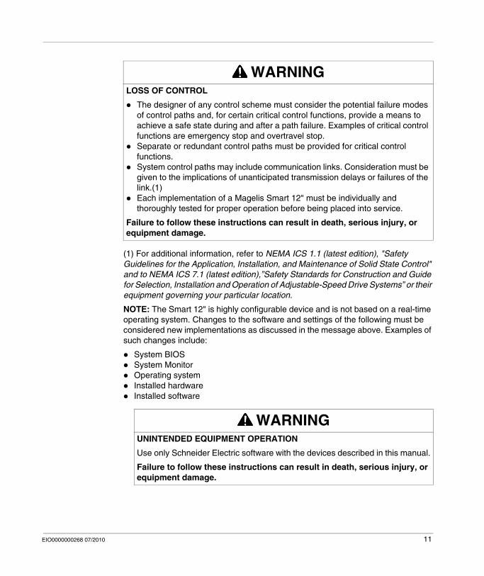
(1) For additional information, refer to NEMA ICS 1.1 (latest edition), "Safety Guidelines for the Application, Installation, and Maintenance of Solid State Control" and to NEMA ICS 7.1 (latest edition),”Safety Standards for Construction and Guide for Selection, Installation and Operation of Adjustable-Speed Drive Systems” or their equipment governing your particular location.
NOTE: The Smart 12" is highly configurable device and is not based on a real-time operating system. Changes to the software and settings of the following must be considered new implementations as discussed in the message above. Examples of such changes include:
System BIOSSystem MonitorOperating systemInstalled hardwareInstalled software
WARNINGLOSS OF CONTROL
The designer of any control scheme must consider the potential failure modes of control paths and, for certain critical control functions, provide a means to achieve a safe state during and after a path failure. Examples of critical control functions are emergency stop and overtravel stop.Separate or redundant control paths must be provided for critical control functions.System control paths may include communication links. Consideration must be given to the implications of unanticipated transmission delays or failures of the link.(1)Each implementation of a Magelis Smart 12" must be individually and thoroughly tested for proper operation before being placed into service.
Failure to follow these instructions can result in death, serious injury, or equipment damage.
WARNINGUNINTENDED EQUIPMENT OPERATION
Use only Schneider Electric software with the devices described in this manual.
Failure to follow these instructions can result in death, serious injury, or equipment damage.
EIO0000000268 07/2010 11

User Comments
We welcome your comments about this document. You can reach us by e-mail at [email protected].
12 EIO0000000268 07/2010

EIO0000000268 07/2010
I
General Overview
EIO0000000268 07/2010
General Overview
Subject of this Part
This part provides an overview of the Magelis Compact 12’’ product.
What's in this Part?
This part contains the following chapters:
Chapter Chapter Name Page
1 Important Information 15
2 Physical Overview 23
3 Characteristics 31
4 Dimensions/Assembly 37
13

General Overview
14 EIO0000000268 07/2010

EIO0000000268 07/2010
1
Important Information
EIO0000000268 07/2010
Important Information
General
This chapter describes safety aspects which are specific to the operation of the Compact.
What's in this Chapter?
This chapter contains the following topics:
Topic Page
Federal Communications Commission Radio Frequency Interference Statement - For U.S.A.
16
Qualified Personnel 17
Safety Information for the UK 18
Certifications and Standards 20
European (CE) Compliance 21
15
Important Information
Federal Communications Commission Radio Frequency Interference Statement - For U.S.A.
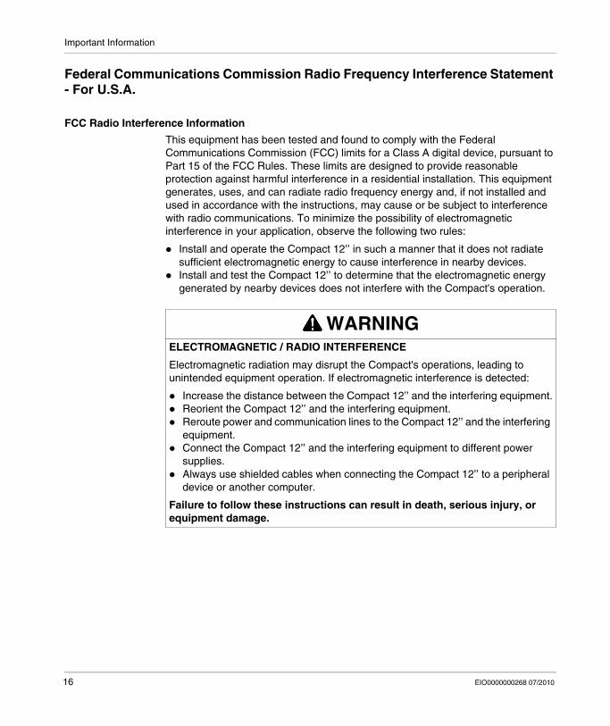
FCC Radio Interference Information
This equipment has been tested and found to comply with the Federal Communications Commission (FCC) limits for a Class A digital device, pursuant to Part 15 of the FCC Rules. These limits are designed to provide reasonable protection against harmful interference in a residential installation. This equipment generates, uses, and can radiate radio frequency energy and, if not installed and used in accordance with the instructions, may cause or be subject to interference with radio communications. To minimize the possibility of electromagnetic interference in your application, observe the following two rules:
Install and operate the Compact 12’’ in such a manner that it does not radiate sufficient electromagnetic energy to cause interference in nearby devices.Install and test the Compact 12’’ to determine that the electromagnetic energy generated by nearby devices does not interfere with the Compact's operation.
WARNINGELECTROMAGNETIC / RADIO INTERFERENCE
Electromagnetic radiation may disrupt the Compact's operations, leading to unintended equipment operation. If electromagnetic interference is detected:
Increase the distance between the Compact 12’’ and the interfering equipment.Reorient the Compact 12’’ and the interfering equipment.Reroute power and communication lines to the Compact 12’’ and the interfering equipment.Connect the Compact 12’’ and the interfering equipment to different power supplies.Always use shielded cables when connecting the Compact 12’’ to a peripheral device or another computer.
Failure to follow these instructions can result in death, serious injury, or equipment damage.
16 EIO0000000268 07/2010
Important Information
Qualified Personnel
General
You must only permit qualified personnel to install, operate, and maintain these products. A qualified person is one who has skills and knowledge related to the constructions and operation of this electrical equipment and the installations, and has received safety training to recognize and avoid the hazards involved. Refer to the most current release of NFPA 70E®, Standard for Electrical Safety in the Workplace, for electrical safety training requirements. Examples of qualified personnel may include:
at the application design level, engineering department personnel who are familiar with automation safety concepts (for example, a design engineer),at the equipment implementation level, personnel who are familiar with the installation, connection and commissioning of automation equipment (for example, an installation assembly or cabling engineer, or a commissioning technician),at the operation level, personnel who are experienced in the use and control of automation and computing equipment (for example, an operator),as far as preventive or corrective maintenance is concerned, personnel trained and qualified in regulating or repairing automatic and computing devices (for example an operating technician, or an after-sales service technician, etc.).
EIO0000000268 07/2010 17

Important Information
Safety Information for the UK
Earthing and Wiring
NOTE: The fact that the equipment operates satisfactorily does not imply that the power point is earthed. If you have any doubt about the effective earthing or wiring of the power point, consult a qualified electrician.
WARNINGUNGROUNDED EQUIPMENT
This apparatus must be earthed.Use a three-pin plug with a standard three-pin power point.Use only three-core extension cords.
Failure to follow these instructions can result in death, serious injury, or equipment damage.
WARNINGIMPROPER WIRING
Wire the equipment as described below:
Green and Yellow: Earth.Blue: Neutral.Brown: Live.The Green and Yellow wire must be connected to the terminal in the plug marked by the letter E or by the safety earth symbols colored Green, or Green and Yellow.The blue wire must be connected to the terminal which is marked by the letter N or colored Black.The brown wire must be connected to the terminal which is marked with the letter L or colored Red.
Failure to follow these instructions can result in death, serious injury, or equipment damage.
18 EIO0000000268 07/2010

Important Information
WARNINGINCOMPATIBLE POWER SYSTEM
Do not connect this equipment to an isolation transformer power system:
An isolation transformer system is a system having no reference between live parts and Earth; the exposed conductive parts of the device frame and enclosure are earthed.An isolation transformer system is not permitted where the computer is directly connected to public supply systems in the UK.
Failure to follow these instructions can result in death, serious injury, or equipment damage.
EIO0000000268 07/2010 19

Important Information
Certifications and Standards
Agency Certifications
The following agencies have certified this product as meeting the standards listed afterwards.
North America:Underwriters Laboratories Inc., UL 508/cUL, Industrial Control Equipment
Compliance Standards
Schneider Electric tested this product for compliance with the following compulsory standards.
North America:Federal Communications Commission, FCC Part 15Underwriters Laboratories Inc., UL 60950, Information Technology Equipment
Canada:Canadian Standards Association, specification C22.2, No.142, Process Control Equipment
Europe: CEDirective 2006/95/EC (Low Voltage)Directive 2004/108/EC (EMC)Programmable Controllers: IEC/EN 61131-2EMI: EN55011 (Group 1, Class A) / IEC/EN 61000-3-2, IEC/EN 61000-6-4EMS: EN 61000-6-2IEC/EN 60950, Information Technology Equipment
Australia:C-Tick N998Standard AS/NZS CISPR11
Qualification Standards
Schneider Electric voluntarily tested this product to additional standards. The additional tests performed, and the standards under which the tests were conducted, are specifically identified in Environmental Characteristics (see page 35).
Hazardous Substances
This product is compliant with:WEEE, Directive 2002/96/ECRoHS, Directive 2002/95/ECRoHS China, Standard SJ/T 11363-2006
20 EIO0000000268 07/2010

Important Information
European (CE) Compliance
CE Compliance Note
The products described in this manual comply with the European Directives concerning Electromagnetic Compatibility and Low Voltage (CE marking) when used as specified in the relevant documentation, in applications for which they are specifically intended, and in connection with approved third-party products.
EIO0000000268 07/2010 21

Important Information
22 EIO0000000268 07/2010

EIO0000000268 07/2010
2
Physical Overview
EIO0000000268 07/2010
Physical Overview
Subject of this Chapter
This chapter provides a physical overview of the product.
What's in this Chapter?
This chapter contains the following topics:
Topic Page
Package Contents 24
Compact Unit Description 26
Interface Specification 29
23

Physical Overview
Package Contents
Items
The following items are included in the Magelis Compact 12’’ package. Before using the unit, please confirm that all items listed here are present.
Designation Figure
MPC KT22 ••• ••
Installation Fasteners (4 per set)
CD-ROM containing the software required to reinstall the Operating System, the Installation Guide, this User Manual documentation, and the MS Windows EULA. (All product references)
Gasket
USB Cover x 2
24 EIO0000000268 07/2010

Physical Overview
This unit has been carefully packed, with special attention to quality. However, should you find anything damaged or missing, please contact your local distributor immediately.
USB Holder x 4
AC Power Cord with Terminal Block (US plug)(For the Compact 12’’ AC only, references MPC KT 22 •AX 2••)
AC Power Cord with Terminal Block (EU plug)(For the Compact 12’’ AC only, references MPC KT 22 •AX 2••)
Designation Figure
EIO0000000268 07/2010 25

Physical Overview
Compact Unit Description
Front View
A DisplayB Touch PanelC Power LED/RAS Status Lamp
Green Lit: NormalGreen Blinking: System is not running (Soft OFF state)Orange Lit: System Monitor ErrorOrange/Red Blinking: Backlight ErrorNot Illuminated: Power is Off
D Hard Disk Drive (HDD)/IDE Access LampGreen Lit: Access to HDD or IDENot Illuminated: No Access to HDD or IDE
E Front USB Cover
NOTE: Soft OFF: OS is shut down but the power line is still live. This is also called S5 state. One of the merits of this state is that you can also use the Wake on LAN feature.
26 EIO0000000268 07/2010

Physical Overview
Rear View
F Power SwitchG Power Supply ConnectorH Fan UnitI Expansion Board BaseJ Expansion Board CoverK Expansion Board Support
I J K
F
G
H
EIO0000000268 07/2010 27

Physical Overview
Side View
L USB InterfaceM PCMCIA
Bottom View
N Ethernet LAN2 10/100/1000Base-T (RJ45)O Ethernet LAN1 10/100Base-T (RJ45)P Speaker Output InterfaceQ RAS InterfaceR Serial Interface (COM1)S CF Card CoverT Expansion Slot
N PO Q R S
T
28 EIO0000000268 07/2010

Physical Overview
Interface Specification
Communication Connections
Serial Interfaces
This interface is used to connect an RS-232C (serial) cable. A D-SUB 9 pin plug connector is used.
WARNINGEQUIPMENT DISCONNECTION OR UNINTENDED EQUIPMENT OPERATION
Ensure that power, communication, and accessory connections do not place excessive stress on the ports. Consider the vibration environment when making this determination.Securely attach power, communication, and external accessory cables to the panel or cabinet.Use only commercially available USB cables.
Failure to follow these instructions can result in death, serious injury, or equipment damage.
PIn Arrangement Pin No. RS-232C
Signal Name
Direction Meaning
1 CD Input Carrier Detect
2 RXD Input Receive Data
3 TXD Output Send Data
4 DTR Output Data Terminal Ready
5 SG – Signal Ground
6 DSR Input Data Set Ready
7 RTS Output Request to Send
8 CTS Input Send Possible
9 RI Input Called status display/+ 5 Vdc
Shell FG – Frame Ground (Common with SG)
EIO0000000268 07/2010 29
Physical Overview
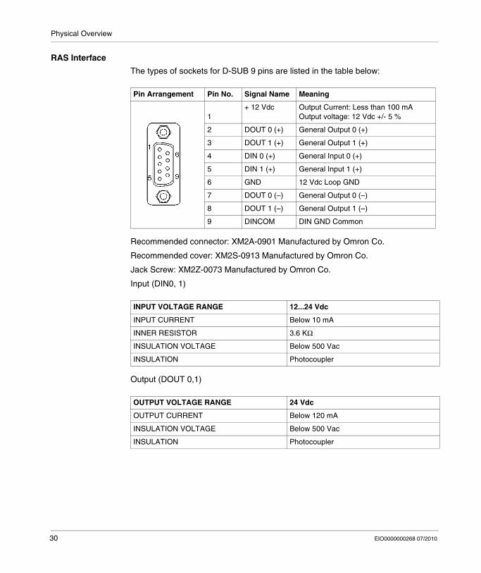
RAS Interface
The types of sockets for D-SUB 9 pins are listed in the table below:
Recommended connector: XM2A-0901 Manufactured by Omron Co.
Recommended cover: XM2S-0913 Manufactured by Omron Co.
Jack Screw: XM2Z-0073 Manufactured by Omron Co.
Input (DIN0, 1)
Output (DOUT 0,1)
Pin Arrangement Pin No. Signal Name Meaning
1+ 12 Vdc Output Current: Less than 100 mA
Output voltage: 12 Vdc +/- 5 %
2 DOUT 0 (+) General Output 0 (+)
3 DOUT 1 (+) General Output 1 (+)
4 DIN 0 (+) General Input 0 (+)
5 DIN 1 (+) General Input 1 (+)
6 GND 12 Vdc Loop GND
7 DOUT 0 (–) General Output 0 (–)
8 DOUT 1 (–) General Output 1 (–)
9 DINCOM DIN GND Common
INPUT VOLTAGE RANGE 12...24 Vdc
INPUT CURRENT Below 10 mA
INNER RESISTOR 3.6 KΩ
INSULATION VOLTAGE Below 500 Vac
INSULATION Photocoupler
OUTPUT VOLTAGE RANGE 24 Vdc
OUTPUT CURRENT Below 120 mA
INSULATION VOLTAGE Below 500 Vac
INSULATION Photocoupler
30 EIO0000000268 07/2010

EIO0000000268 07/2010
3
Characteristics
EIO0000000268 07/2010
Characteristics
Subject of this Chapter
This chapter lists the product characteristics.
What's in this Chapter?
This chapter contains the following topics:
Topic Page
Characteristics of the Compact 12’’ 32
Flash Disk Characteristics 34
Environmental Characteristics 35
31

Characteristics
Characteristics of the Compact 12’’
Introduction
The characteristics of the Compact 12’’ are given below:
Product Characteristics
NOTE: If a USB high speed device such as a webcam or memory key isn't recognized by the Compact, or doesn't operate as expected, plug it into USB port #2 and leave USB port #1 empty.
Element Characteristics
Processor Celeron® M 1.5 GHz, secondary memory cache 512 KB
RAM 512 MB - 1 GB RAM SO-DIMM DDR 200-pin (PC2700) x1 slot
Hard disk Capacity greater or equal to 160 GB IDE 2.5’’
Or Flash disk Capacity greater or equal to 16 GB (Refer to Flash Disk Characteristics (see page 34)).
Video processor Integrated Intel® chipset video, sharing main memory.
Ethernet TCP/IP link LAN1: 10/100Base-TLAN2: 10/100/1000Base-T
USB ports 4 x USB 2.0 (rear face), 1 x USB 1.1 (front face)
RAS Interface General Input 2 ch (DIN1 can be used as Reset Input), General Output 2 ch (can be used as Alarm Output). Connector: D-SUB 9 Pin Plug (female)
COM 1 serial ports RS232C
RGB port D-SUB 15 Pin x1 (female)
Extension card slot 1 PCI 2.2 interface slot
Memory flash card slot Compact Flash type
PCMCIA slot 1 port on side (Type II)
Audio port Stereo speaker out (stereo mini-jack)
Dimensions (WxHxD) 313 x 239 x 103 mm (12.32 x 9.41 x 4.06 in.)
Weight 4.5 kg (9.9 lb)
32 EIO0000000268 07/2010

Characteristics
Display Characteristics
Power Supply
For the Compact 12’’ AC (References MPC KT 22 NAX 2••):
Operating Systems
The products are delivered with a pre-installed operating system according to the reference ordered.
The products have been tested with the following operating systems: all versions of Microsoft Windows® XP Pro (SP2 and above) operating system.
Element Characteristics
Graphics XGA TFT active matrix (1024x768 pixels)
Number of colors 260 K colors
Brightness 245 cd/m² (typical value)
Brightness Control 4 levels of adjustment
View angle Vertical 100° , horizontal 120° maximum
Touch sensitive screen Analog resistive film, resolution 1024x1024
Backlight CFL - Life span > 50,000 h at 25° C (77° F)
Element Characteristics
Supply voltage 100...240 Vac (Range 85 ... 265 Vac)
Consumption 110 VA (max.)
Short dips 10 ms (20 ms max.)
PCI extension slot capability
Board size 240 x 106.68 mm (9.45 x 4.2 in.)5 Vdc, 1.5 A12 Vdc, 0.5 A12 Vdc, 0.1 A3.3 Vdc, 0.5 A
Reference Characteristics
MPC KT22 NAX 2•N Compact with 12’’ XGA Display, Touch screen, Pentium® M 1.5 GHz, 160 GB HDD, Windows® XP Pro (all versions, SP2 and above) pre-installed, AC supply power.
MPC KT22 MAX 2•N Compact with 12’’ XGA Display, Touch screen, Pentium® M 1.5 GHz, 16 GB Flash Disk, Windows® XP Pro (all versions, SP2 and above) pre-installed, AC supply power.
MPC KT22 MAX 2•H Compact with 12’’ XGA Display, Touch screen, Pentium® M 1.5 GHz, 16 GB Flash Disk, Windows® XP Pro (all versions, SP2 and above) with Vijeo Designer Runtime pre-installed, AC supply power.
EIO0000000268 07/2010 33

Characteristics
Flash Disk Characteristics
Introduction
Two Compact 12’’ product references offer Flash Disk hard drives (also known as Solid-State Drives or SSDs). There is also a Flash Disk accessory available for use as a replacement or backup hard disk drive. All Flash Disk references are SATA compliant and have no moving parts.
Characteristics
A Flash Disk (SSD) is a storage device based on semiconductors rather than rotating magnetic platters. The use of semiconductors allows a Flash Disk to perform normal storage functions while providing enhanced levels of performance and reliability. Flash Disk drives use the same industry-standard dimensions and data interfaces as conventional hard disk drives and may be used interchangeably in Compact 12’’ systems.
The references with Flash Disks share the same characteristics as the other Compact 12’’ devices except as noted in following table:
NOTE: The shock and vibration operating limits for a Compact 12’’ with a Flash Disk are higher than for references with conventional hard disks. If other Flash Disk and Compact 12’’ operating limits differ, the more restrictive limits apply.
Characteristics Values Standards
Capacity 16 GB or higher —
MTBF >4,000,000 Hours at 25° C (77° F) —
Data Reliability < 1 Non-Recoverable Error in 1014 Bits Read —
Endurance > 2,000,000 write/erase cycles —
Shock resistance (in operation) 15 g over 11 ms, 3 shocks per axis IEC 68-2-27 Ea testEN 61131-2 compliant
Shock component value 1000 g, half-sine, 0.5 ms duration 50 g peak MIL-STD-810F, Method 516.5, Procedure I
Vibration resistance (in operation) 3.5 mm amplitude from 10 to 57.6 Hz 1 g amplitude from 57.6 Hz to 150 Hz
EN 61131-2 compliant
Vibration component value 16.3 g RMS MIL-STD-810F, Method 514.5, Procedure I, Category 24
34 EIO0000000268 07/2010

Characteristics
Environmental Characteristics
Characteristics
The environmental characteristics of the Compact 12’’ are as follows:
Characteristics Value Standards
Degree of Protection IP 65/NEMA4x/12 for the front panel.IP 20 for the rest of the product.
IEC 60529, NEMA 250, EN 61131-2
Pollution Degree For use in Pollution Degree 2 environment
–
Surrounding air temperature during operation
0 ... 50 ° C (41 ... 122 ° F) EN 61131-2, UL1604 compliant
Storage temperature – 20 ... 60 ° C ( – 4 ... 140 ° F) IEC 60068-2-2 tests Bb and Ab, IEC 60068-2-14 tests Na and EN 61131-2 compliant
Operating altitude 2000 m (6560 ft) max EN 61131-2
Vibration(storage)
3.5 mm amplitude from 5 to 9 Hz,1 g amplitude from 9 Hz to 150 Hz
EN 61131-2
Vibration(in operation)
0.075 mm amplitude from 10 to 57.6 Hz,1 g amplitude from 57.6 Hz to 150 Hz
EN 61131-2
Shock Resistance(in operation)
15 g over 11 ms IEC 60068-2-27 Ea testand EN 61131-2 compliant
Surrounding air humidity during operation
10 ... 85% RH (Wet bulb temperature: 29 ° C (84.2 ° F) max. - no condensation)
–
Storage humidity 10 ... 85% RH (Wet bulb temperature: 29 ° C (84.2 ° F) max. - no condensation)
EN 61131-2
Immunity to interference High frequency interference EN 61131-2, IEC 61000-4-3/6 level 3
Electromagnetic waves Class A/EN 55022/55011
Additional Standards Information Technology Equipment IEC 60950
Industrial Control Equipment UL 508 / cUL
EIO0000000268 07/2010 35

Characteristics
36 EIO0000000268 07/2010

EIO0000000268 07/2010
4
Dimensions/Assembly
EIO0000000268 07/2010
Dimensions/Assembly
Subject of this Chapter
This chapter concerns the dimensions and the panel mounting of products.
What's in this Chapter?
This chapter contains the following topics:
Topic Page
Dimensions 38
Panel Mounting 41
Preparing to Install the 12’’ Compact 43
37

Dimensions/Assembly
Dimensions
Dimensions of the Compact iPC Unit
38 EIO0000000268 07/2010

Dimensions/Assembly
Installation Fastener Dimensions
The products are designed to be mounted in a cabinet with the attachments described below:
EIO0000000268 07/2010 39
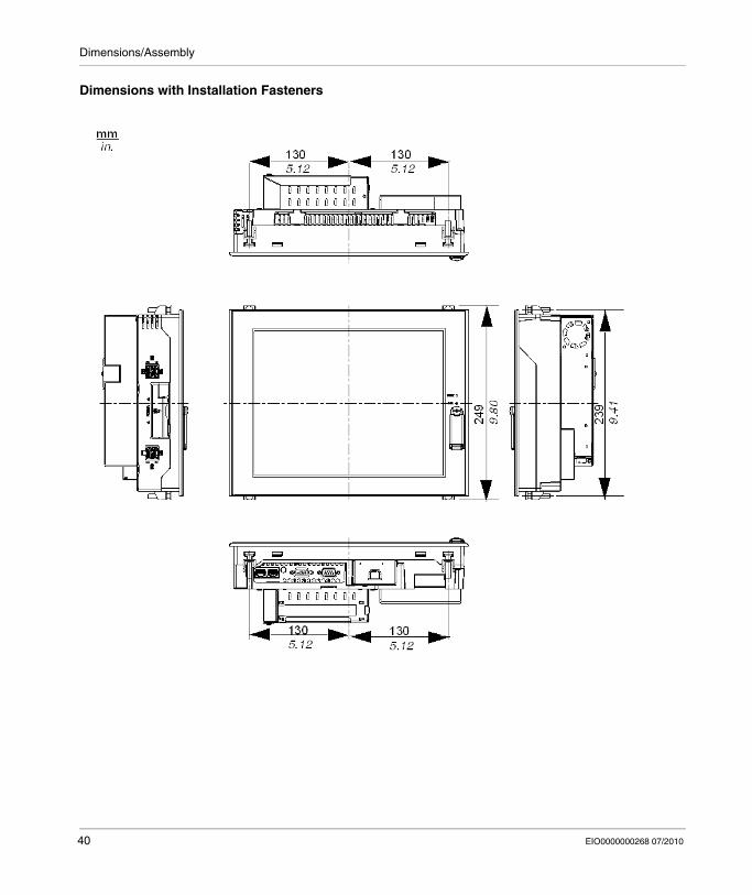
Dimensions/Assembly
Dimensions with Installation Fasteners
40 EIO0000000268 07/2010

Dimensions/Assembly
Panel Mounting
Installation Location
Creating a Panel Cut-out for Cabinet Installation
For cabinet installation, it is necessary for the correct sized opening to be cut in the installation panel. The installation gasket and installation fasteners are required when installing the Compact.
WARNINGUNINTENDED EQUIPMENT OPERATION
Overheating can cause incorrect software behavior, therefore:
Avoid placing the Compact unit next to other devices that might cause overheating.Keep the Compact unit away from arc-generating devices such as magnetic switches and non-fused breakers.Avoid using the Compact unit in environments where corrosive gases are present.Install the Compact in a location providing a minimum clearance of 50 mm (2 in.) or more from all adjacent structures and equipment.Install the Compact with sufficient clearance to provide for cable routing and cable connector dimensions.
Failure to follow these instructions can result in death, serious injury, or equipment damage.
EIO0000000268 07/2010 41

Dimensions/Assembly
Dimensions
The dimensions of the opening required to install the Compact are shown below:
NOTE:
Ensure the thickness of the installation panel is from 1.6 to 10 mm (0.06 to 0.39 in.)All panel surfaces used should be strengthened. Due consideration should be given to the product’s weight, especially if high levels of vibration are expected and the product’s installation surface can move. Metal reinforcing strips can be attached to the inside of the panel near the panel cut-out, to increase the strength of the panel.Ensure all installation tolerances are maintained.The Compact 12’’ is designed for use in a NEMA Type 4X or 12 enclosure.
42 EIO0000000268 07/2010

Dimensions/Assembly
Preparing to Install the 12’’ Compact
Vibration and Shocks
Extra care should be taken with respect to the specification concerning vibration levels (Refer to Environmental Characteristics - Vibration (see page 35)) when installing or moving the Compact unit. If the Compact unit is moved, for example, while it is installed in a rack equipped with caster wheels, the unit can receive excessive shock and vibration.
CAUTIONEXCESSIVE VIBRATION
Plan your installation activities so that device shock and vibration tolerances are not exceeded.Ensure that the panel opening and thickness are within the specified tolerances.Before mounting the Compact unit into a cabinet or panel, ensure that the installation gasket is attached to the unit. The installation gasket provides additional protection from vibration.The recommended torque for mounting the Compact 12’’ device is 0.5 N•m (4.5 lb-in).
Failure to follow these instructions can result in injury or equipment damage.
EIO0000000268 07/2010 43

Dimensions/Assembly
Installation Gasket
Use of the installation gasket may help extend the operating life of your Compact. The gasket is required to meet the protection ratings (IP65, IP20) of the unit and provides additional protection from vibration. Even if moisture protection is not required, install the gasket delivered with your Magelis product.
The corresponding gasket is provided in the maintenance kit ref: MPC YK 20 MNT KIT.
Installation Fasteners
NOTE: The screw installation fasteners are required for NEMA4 protection.
CAUTIONLOSS OF SEAL
Inspect the installation gasket prior to installation or reinstallation, and periodically as required by your operating environment.Replace the gasket if visible scratches, tears, dirt, or excessive wear are noted during inspection.Do not stretch the gasket unnecessarily or allow the gasket to contact the corners or edges of the frame.Ensure that the gasket is fully seated in the installation groove.Install the Compact into a panel that is flat and free of scratches or dents.Tighten the installation fasteners using a torque of 0.5 N•m (4.5 lb-in).
Failure to follow these instructions can result in injury or equipment damage.
CAUTIONOVERTORQUE AND LOOSE HARDWARE
Do not exert more than 0.6 N•m (5.3 lb-in) of torque when tightening the installation fastener, enclosure, accessory, or terminal block screws.Tightening the screws with excessive force can damage the plastic casing of the Compact 12’’.When installing or removing screws, ensure that they do not fall inside the Compact 12’’ unit's chassis.
Failure to follow these instructions can result in injury or equipment damage.
44 EIO0000000268 07/2010

Dimensions/Assembly
Installing the Compact Unit
Follow the steps given below when installing the Compact unit.
Step Action
1 Place the unit face down on a dry, soft surface and attach the gasket to the rear side in the installation groove (see picture below).
2 Check that the gasket is correctly attached to the unit. The upper surface of the gasket should protrude evenly approximately 2 mm (0.08 in.) out of the groove.
EIO0000000268 07/2010 45

Dimensions/Assembly
3 Installation FastenersInsert each installation fastener securely into the slot’s recess at the top and bottom of the unit.
4 Attaching and Securing the Rear Installation Attachments
NOTE:
To permit a high degree of moisture resistance, the torque should be 0.5 N•m (4.5 lb-in).The corresponding installation attachments can be purchased as spare parts with the maintenance kit ref: MPC YK 20 MNT KIT.
Step Action
46 EIO0000000268 07/2010

Dimensions/Assembly
5 Insert each of the fasteners. Pull the fastener back until it is flush with the rear of the attachment hole.NOTE: The corresponding installation attachments can be purchased as spare parts with the maintenance kit ref.: MPC YK 20 MNT KIT.
6 Use a screw driver to tighten each fastener screw to 0.5 N•m (4.5 lb-in).
7 Compact unit Viewing AngleEnsure that the panel’s viewing angle is tilted no more than 30 degrees from parallel to the operator (i.e. operator is directly in front).
Step Action
EIO0000000268 07/2010 47

Dimensions/Assembly
48 EIO0000000268 07/2010
EIO0000000268 07/2010
II
Implementation
EIO0000000268 07/2010
Implementation
Subject of this Part
This part describes the implementation of the product.
What's in this Part?
This part contains the following chapters:
Chapter Chapter Name Page
5 Getting Started 51
6 Main Power Connection 53
7 Configuration of the BIOS 59
8 Hardware Modifications 63
49

Implementation
50 EIO0000000268 07/2010

EIO0000000268 07/2010
5
Getting Started
EIO0000000268 07/2010
Getting Started
First Power-up
NOTE: Limitations on your usage of the Windows® XP Pro Operating System (all versions, SP2 and above) are noted in Microsoft's End User License Agreement (EULA). This EULA is included on the CD-ROM. Please read this document before first power-up.
Preparation
On the first power-up of your MPC••, it is necessary to customize and set the parameters for your system. Refer to the Magelis Installation Guide for assistance in installing, customizing and parameterizing your Schneider Electric applications (Unity Pro, PL7 Junior or PL7 Pro, Vijeo Designer, Vijeo Designer Lite, OFS, MMI 17, XBT-L1000, PL7-07).
51
Getting Started
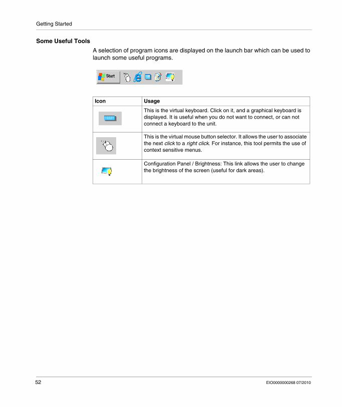
Some Useful Tools
A selection of program icons are displayed on the launch bar which can be used to launch some useful programs.
Icon Usage
This is the virtual keyboard. Click on it, and a graphical keyboard is displayed. It is useful when you do not want to connect, or can not connect a keyboard to the unit.
This is the virtual mouse button selector. It allows the user to associate the next click to a right click. For instance, this tool permits the use of context sensitive menus.
Configuration Panel / Brightness: This link allows the user to change the brightness of the screen (useful for dark areas).
52 EIO0000000268 07/2010

EIO0000000268 07/2010
6
Main Power Connection
EIO0000000268 07/2010
Main Power Connection
Subject of this Chapter
This chapter describes the connection of the Compact 12’’ to the mains power supply.
What's in this Chapter?
This chapter contains the following topics:
Topic Page
Grounding 54
Connecting the AC Power Cord 57
53
Main Power Connection
Grounding
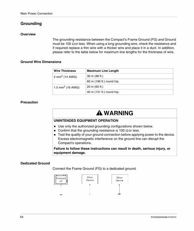
Overview
The grounding resistance between the Compact’s Frame Ground (FG) and Ground must be 100 Ω or less. When using a long grounding wire, check the resistance and if required replace a thin wire with a thicker wire and place it in a duct. In addition, please refer to the table below for maximum line lengths for the thickness of wire.
Ground Wire Dimensions
Precaution
Dedicated Ground
Connect the Frame Ground (FG) to a dedicated ground.
Wire Thickness Maximum Line Length
2 mm2 (14 AWG) 30 m (98 ft.)
60 m (196 ft.) round trip.
1.5 mm2 (16 AWG) 20 m (65 ft.)
40 m (131 ft.) round trip.
WARNINGUNINTENDED EQUIPMENT OPERATION
Use only the authorized grounding configurations shown below.Confirm that the grounding resistance is 100 Ω or less.Test the quality of your ground connection before applying power to the device. Excess electromagnetic interference on the ground line can disrupt the Compact's operations.
Failure to follow these instructions can result in death, serious injury, or equipment damage.
54 EIO0000000268 07/2010

Main Power Connection
Shared Ground Allowed
If a dedicated ground is not possible, use a shared ground, as shown below.
Shared Ground not Allowed
Do not connect the Compact 12’’ unit to ground through other devices using the SG terminal.
Shared Ground - Avoid Ground Loop
When connecting an external device to a Compact with the Shield Ground (SG), ensure that no ground loop is created. The Compact’s FG and SG are connected internally.
EIO0000000268 07/2010 55
Main Power Connection
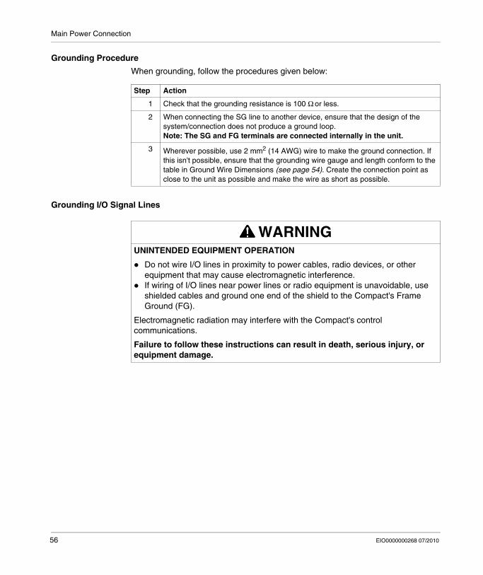
Grounding Procedure
When grounding, follow the procedures given below:
Grounding I/O Signal Lines
Step Action
1 Check that the grounding resistance is 100 Ω or less.
2 When connecting the SG line to another device, ensure that the design of the system/connection does not produce a ground loop.Note: The SG and FG terminals are connected internally in the unit.
3 Wherever possible, use 2 mm2 (14 AWG) wire to make the ground connection. If this isn't possible, ensure that the grounding wire gauge and length conform to the table in Ground Wire Dimensions (see page 54). Create the connection point as close to the unit as possible and make the wire as short as possible.
WARNINGUNINTENDED EQUIPMENT OPERATION
Do not wire I/O lines in proximity to power cables, radio devices, or other equipment that may cause electromagnetic interference.If wiring of I/O lines near power lines or radio equipment is unavoidable, use shielded cables and ground one end of the shield to the Compact's Frame Ground (FG).
Electromagnetic radiation may interfere with the Compact's control communications.
Failure to follow these instructions can result in death, serious injury, or equipment damage.
56 EIO0000000268 07/2010
Main Power Connection
Connecting the AC Power Cord
Precaution
When connecting the Compact unit’s power cord to the power connector on the unit, first ensure that the power cord is disconnected from the main power supply.
DANGERHAZARD OF ELECTRIC SHOCK, EXPLOSION OR ARC FLASH
Remove all power from the device before removing any covers or elements of the system and prior to installing or removing any accessories, hardware, or cables.Always use a properly rated voltage sensing device to confirm power is off.Unplug the power cable from both the Compact unit and the power supply.Replace and secure all covers or elements of the system before applying power to the unit.Use only the specified voltage when operating the Compact 12’’. The AC unit is designed to use 100...240 Vac input.
Failure to follow these instructions will result in death or serious injury.
WARNINGEQUIPMENT DISCONNECTION OR UNINTENDED EQUIPMENT OPERATION
Ensure that power, communication, and accessory connections do not place excessive stress on the ports. Consider the vibration environment when making this determination.Securely attach power, communication, and external accessory cables to the panel or cabinet.Use only commercially available USB cables.
Failure to follow these instructions can result in death, serious injury, or equipment damage.
EIO0000000268 07/2010 57

Main Power Connection
Power Cord Connection (AC Compact Version)
The table below describes how to connect the power cord to the Compact unit:
Step Action
1 Connect the power cord (refer to Package Contents (see page 24)) to the terminal block as shown below:
2 Place and screw the terminal block to 0.5 to 0.6 N•m (4.5 to 5.3 lb-in), (refer to Package Contents (see page 24)) on the Compact unit’s power connector.
TerminalBlock
PowerConnector
58 EIO0000000268 07/2010

EIO0000000268 07/2010
7
Configuration of the BIOS
EIO0000000268 07/2010
Configuration of the BIOS
Accessing the BIOS
Overview
NOTE: Normally, factory (defaults) settings should be used.
Connect a USB keyboard to the Compact unit.
Turn the power on to the Compact unit and when prompted to do so, press the F2 key to enter the BIOS.
Main Menu
Selecting the Main menu item displays the following screen:
NOTE: When you have finished entering the parameters, press the Esc to reach the Exit menu. Here you will be prompted either to exit saving the changes, or to exit without saving the changes as described below.
59
Configuration of the BIOS
System Time
Time (hh:mm:ss)
This field shows the present Compact unit time from the internal clock. The hh/mm/ss (00:00:00) format is factory set prior to shipping.
Hours: 00 to 23
Minutes: 00 to 59
Seconds: 00 to 59
The correct time can be set by using the [+] and [-] keys.
System Date
Date (yy:mm:dd)
This field shows the Compact unit’s internal calendar. The correct date can be set by using the [+] and [-] keys.
Year: 1999 to 2099
Month: Jan/Feb/Mar/Apr/May/Jun/Jul/Aug/Sep/Oct/Nov/Dec
Day: 1 to 31
Primary Master
Displays the name of the devices connected to the primary bus of the Compact unit. Pressing the Enter key will call up the Parameter Settings menu.
Primary Slave
Displays the name of the devices connected to the secondary bus of the Compact unit. Pressing the Enter key will call up the Parameter Settings menu.
System Memory
Displays the capacity of the System Memory.
Extended Memory
Displays the capacity of the Extended Memory.
60 EIO0000000268 07/2010
Configuration of the BIOS
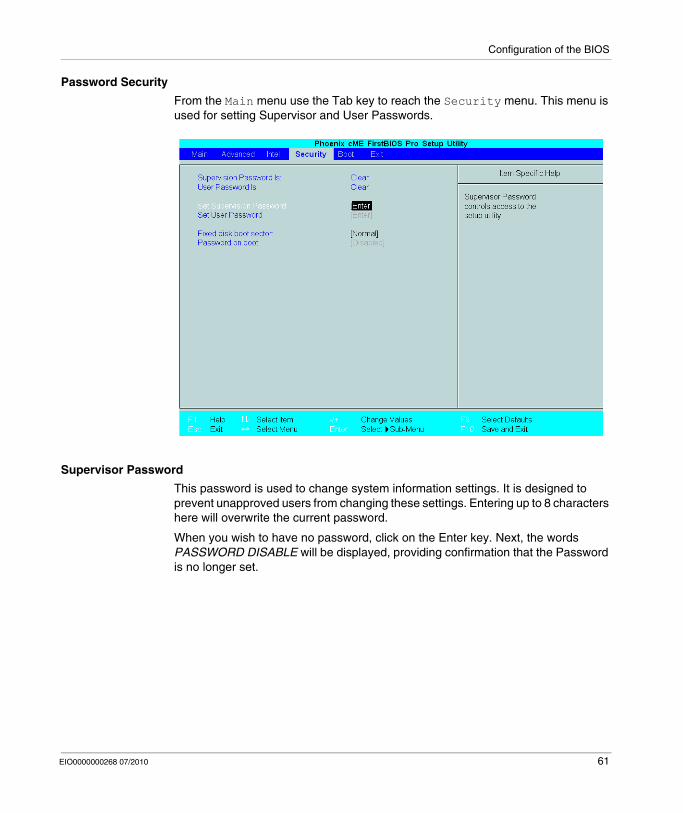
Password Security
From the Main menu use the Tab key to reach the Security menu. This menu is used for setting Supervisor and User Passwords.
Supervisor Password
This password is used to change system information settings. It is designed to prevent unapproved users from changing these settings. Entering up to 8 characters here will overwrite the current password.
When you wish to have no password, click on the Enter key. Next, the words PASSWORD DISABLE will be displayed, providing confirmation that the Password is no longer set.
EIO0000000268 07/2010 61

Configuration of the BIOS
User Password
This password is used to view system information settings. It is designed to prevent unapproved users from viewing the system information settings. Entering up to 8 characters here will overwrite the current password.
When you wish to have no password, click on the Enter key. Next, the words PASSWORD DISABLE will be displayed, providing confirmation that the Password is no longer set.
NOTE:
Without having defined a Supervisor Password, it is not possible to define a User Password.When using Set Supervisor Password, you can easily view and change the system settings.When using only Set User Password, you will be allowed to view the system data only, not change it.
Exit BIOS saving the Modifications
This feature saves the settings entered in the Setup Utility and restarts the Compact unit.
Exit BIOS Without Saving Modifications
This feature quits the Setup Utility program without saving any settings entered.
62 EIO0000000268 07/2010

EIO0000000268 07/2010
8
Hardware Modifications
EIO0000000268 07/2010
Hardware Modifications
Subject of this Chapter
This chapter concerns the hardware modifications for the Magelis Compact 12’’.
A wide variety of optional units, Main Memory and CF cards manufactured by Schneider Electric, and commercial expansion boards (PCI bus compatible board) or PCMCIA (PC Cards) can be used with this product.
What's in this Chapter?
This chapter contains the following topics:
Topic Page
Before Modifications 64
Installing a Larger RAM Chip 66
Expansion Board (PCI) Installation 68
PCMCIA Card Installation 70
Compact Flash (CF) Card Installation and Removal 73
USB Holder Attachment/Removal 76
Hard Disk Drive (HDD) Unit Installation 79
63

Hardware Modifications
Before Modifications
Overview
For the detailed installation procedures for the optional units, refer to the OEM (Original Equipment Manufacturer) Installation Guide included with the optional unit.
DANGERHAZARD OF ELECTRIC SHOCK, EXPLOSION OR ARC FLASH
Remove all power from the device before removing any covers or elements of the system, and prior to installing or removing any accessories, hardware, or cables.Always use a properly rated voltage sensing device to confirm power is off.Unplug the power cable from both the Compact unit and the power supply.Replace and secure all covers or elements of the system before applying power to the unit.Use only the specified voltage when operating the Compact 12’’. The AC unit is designed to use 100...240 Vac input.
Failure to follow these instructions will result in death or serious injury.
DANGERCHEMICAL BURNS TO EYES OR SKIN
Do not use tools to operate the touch panel or in the vicinity of the display.When placing the display face-down, select a clean, level, non-abrasive surface. If necessary, place a soft, non-abrasive pad on the surface before lowering the unit.If a leak in the LCD panel is discovered and you come in contact with the liquid crystal material, follow these procedures:
In the case of contact with eyes or mouth, flush with running water for 15 minutes minimum.In the case of contact with skin or clothing, wipe off the liquid crystal material and wash with soap and running water for 15 minutes.If liquid crystal is ingested, induce vomiting, rinse mouth, and then drink a large quantity of water.Follow any other hazardous substances safety procedures required by your facility.
Failure to follow these instructions will result in death or serious injury.
64 EIO0000000268 07/2010

Hardware Modifications
Precautions to be taken:
Keep static-producing materials (plastic, upholstery, carpeting) out of the immediate work area.Do not remove ESD-sensitive components from their anti-static bags until you are ready to install them.When handling static-sensitive components, wear a properly grounded wrist strap (or equivalent).Avoid unnecessary contact with exposed conductors and component leads with skin or clothing.
CAUTIONOVERTORQUE AND LOOSE HARDWARE
Do not exert more than 0.6 N•m (5.3 lb-in) of torque when tightening the installation fastener, enclosure, accessory, or terminal block screws. Tightening the screws with excessive force can damage the plastic casing of the Compact 12’’.When installing or removing screws, ensure that they do not fall inside the Compact 12’’ unit's chassis.
Failure to follow these instructions can result in injury or equipment damage.
CAUTIONSTATIC SENSITIVE COMPONENTS
Compact 12’’ internal components, including accessories such as RAM modules and expansion boards, can be damaged by static electricity. Observe the electrostatic precautions below when handling such components.
Failure to follow these instructions can result in equipment damage.
EIO0000000268 07/2010 65

Hardware Modifications
Installing a Larger RAM Chip
General
NOTE: If you install a 1 GB RAM chip, a blue screen will appear for about 4 minutes after you start the terminal. After the installation, the terminal will start as usual.
Installing the RAM Chip
When installing the Main Memory (RAM) module, follow the procedures listed below:
DANGERHAZARD OF ELECTRIC SHOCK, EXPLOSION OR ARC FLASH
Read and understand the safety information on Before Modifications (see page 64) before attempting this procedure.
Failure to follow these instructions will result in death or serious injury.
Step Action
1 Shut down Windows®, in an orderly fashion and remove all power from the device.
2 Place the unit on a clean, level surface with the display facing downwards. Place a soft, non-abrasive pad on the surface before placing the unit upon it.
3 Unscrew the two screws on the memory cover slot.
1 Screw
1
66 EIO0000000268 07/2010
Hardware Modifications
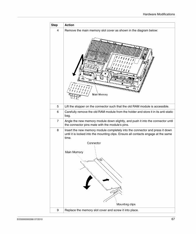
4 Remove the main memory slot cover as shown in the diagram below:
5 Lift the stopper on the connector such that the old RAM module is accessible.
6 Carefully remove the old RAM module from the holder and store it in its anti-static bag.
7 Angle the new memory module down slightly, and push it into the connector until the connector pins mate with the module's pins.
8 Insert the new memory module completely into the connector and press it down until it is locked into the mounting clips. Ensure all contacts engage at the same time.
9 Replace the memory slot cover and screw it into place.
Step Action
EIO0000000268 07/2010 67

Hardware Modifications
Expansion Board (PCI) Installation
Installing the Expansion Board
The table below describes how to install a commercial PCI board.
DANGERHAZARD OF ELECTRIC SHOCK, EXPLOSION OR ARC FLASH
Read and understand the safety information on Before Modifications (see page 64) before attempting this procedure.
Failure to follow these instructions will result in death or serious injury.
Step Action
1 Shut down Windows® in an orderly fashion and remove all power from the device.
2 Place the unit on a clean, level surface with the display facing downwards. Place a soft, non-abrasive pad on the surface before placing the unit upon it.
3 Remove the expansion board support screw and remove the expansion board cover.
68 EIO0000000268 07/2010

Hardware Modifications
4 Unscrew the expansion board cover screws and remove the expansion board cover
5 Unscrew the screw from an empty panel and remove the blank panel. Insert the PCI board into the expansion board connector, and secure it in place using the filler panel’s screw. The necessary torque is 0.5 to 0.6 N•m (4.5 to 5.3 lb-in).
6 Replace the expansion board cover and expansion board support and secure them in place using the screws. The maximum size allowed for an expansion board is 174.68 x 106.68 mm (6.88 x 4.2 in). When using an expansion board of this size, be sure to secure it in place using the expansion board support cover.
Step Action
EIO0000000268 07/2010 69

Hardware Modifications
PCMCIA Card Installation
Overview
Before installing or removing a PCMCIA card, shut down Windows® in an orderly fashion and remove all power from the device.
PCMCIA Cards with Cables
When using a PCMCIA card with an external cable attached, install a clamp or other type of device to secure the cable.
NOTE: PCMCIA types are differentiated by their thickness:
Type I: 3.3 mm (0.13 in)Type II: 5 mm (0.20 in)Type III: 10.5 mm (0.41 in)
DANGERHAZARD OF ELECTRIC SHOCK, EXPLOSION OR ARC FLASH
Read and understand the safety information on Before Modifications (see page 64) before attempting this procedure.
Failure to follow these instructions will result in death or serious injury.
WARNINGEQUIPMENT DISCONNECTION OR UNINTENDED EQUIPMENT OPERATION
Ensure that power, communication, and accessory connections do not place excessive stress on the ports. Consider the vibration environment when making this determination.Securely attach power, communication, and external accessory cables to the panel or cabinet.Use only commercially available USB cables.
Failure to follow these instructions can result in death, serious injury, or equipment damage.
70 EIO0000000268 07/2010

Hardware Modifications
Installing the PCMCIA Card
The table below describes how to install the PCMCIA Card:
Step Action
1 Shut down Windows®, in an orderly fashion and remove all power from the device.
2 Place the unit on a clean, level surface with the display facing downwards. Place a soft, non-abrasive pad on the surface before placing the unit upon it.
3 Before installing or removing a PCMCIA card, ensure that the power supply to unit has been switched OFF.NOTE: Only the lower slot of the PCMCIA is available for use with PC cards. The top slot does not support a PC card. When using a PC card with a cable attached, Schneider recommends using a clamp or other type of device to minimize the likelihood that vibration will dislodge the cable. Be sure to stop the PC card’s driver prior to removing the PC card. If you do not stop the driver before removing the PC Card, the card may become inoperable or the Windows operating system may stop responding.
4 To install a Type I or Type II PCMCIA card, loosen the screw on the side of the PCMCIA slot on the Compact iPC and move the cover to one side.
5 Check the orientation of the PCMCIA card, and then insert it fully into the slot.
6 Reposition the PCMCIA slot cover and tighten the screw.
EIO0000000268 07/2010 71

Hardware Modifications
Removing a PCMCIA Card
The table below describes how to remove a PCMCIA Card:
Step Action
1 Shut down Windows®, in an orderly fashion and remove all power from the device.
2 Place the unit on a clean, level surface with the display facing downwards. Place a soft, non-abrasive pad on the surface before placing the unit upon it.
3 To remove the PCMCIA card: Press both eject buttons twice (Pressing the eject buttons once causes the tip of the card to be exposed. Pressing the eject buttons a second time ejects the PCMCIA card from the slot). Withdraw the PCMCIA card.
4 Reposition the PCMCIA slot cover and tighten the screw.
72 EIO0000000268 07/2010
Hardware Modifications
Compact Flash (CF) Card Installation and Removal
Preparing to Use a CF Card
The Compact's operating system views the CF Card as a hard disk. Proper handling and care of the CF Card helps extend the life of the Card. Familiarize yourself with the Card prior to attempting insertion or removal of the Card.
CAUTIONCOMPACT FLASH (CF) CARD DAMAGE AND DATA LOSS
Remove all power before making any physical contact with an installed CF card.Use only CF cards manufactured by Schneider Electric. The performance of the Compact 12’’ has not been tested using CF cards from other manufacturers.Confirm that the CF card is correctly oriented before insertion.Do not bend, drop, or strike the CF card.Do not touch the CF card connectors.Do not disassemble or modify the CF card.Keep the CF card dry.
Failure to follow these instructions can result in injury or equipment damage.
EIO0000000268 07/2010 73

Hardware Modifications
Inserting the CF Card
The table below describes how to insert the CF Card.
DANGERHAZARD OF ELECTRIC SHOCK, EXPLOSION OR ARC FLASH
Read and understand the safety information on Before Modifications (see page 64) before attempting this procedure.
Failure to follow these instructions will result in death or serious injury.
Step Action
1 Shut down Windows® in an orderly fashion and remove all power from the device.
2 Place the unit on a clean, level surface with the display facing downwards. Place a soft, non-abrasive pad on the surface before placing the unit upon it.
3 Unscrew the CF Card cover’s attachment screw, and remove the CF Card cover.
4 Insert the CF Card firmly into the CF card slot, and check that the eject button pops out:
5 Replace the CF Card cover and fix it in place with the screw.
74 EIO0000000268 07/2010

Hardware Modifications
Removing the CF Card
The table below describes how to remove the CF Card.
Data Writing Limitation
The CF card is limited to approximately 100,000 write operations. Therefore, be sure to back up all CF Card data regularly to another storage media.
Step Action
1 Shut down Windows® in an orderly fashion and remove all power from the device.
2 Place the unit on a clean, level surface with the display facing downwards. Place a soft, non-abrasive pad on the surface before placing the unit upon it. Then, remove the CF card cover as described above.
3 Press the eject button in fully to remove the CF Card from the CF Card slot.
4 After inserting/removing the CF card, be sure to replace the CF Card cover and secure it in place using the attachment screw.Note: The necessary torque is 0.5 to 0.6 N•m (4.5 to 5.3 lb-in).
EIO0000000268 07/2010 75
Hardware Modifications
USB Holder Attachment/Removal
Introduction
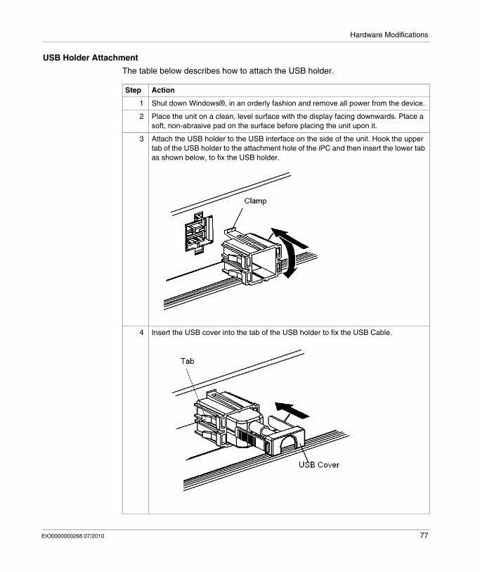
When using a USB device, attaching the USB holder to the USB interface located on the side of the Compact iPC minimizes the likelihood that the USB cable interface will become disconnected.
DANGERHAZARD OF ELECTRIC SHOCK, EXPLOSION OR ARC FLASH
Read and understand the safety information on Before Modifications (see page 64) before attempting this procedure.
Failure to follow these instructions will result in death or serious injury.
WARNINGEQUIPMENT DISCONNECTION OR UNINTENDED EQUIPMENT OPERATION
Ensure that power, communication, and accessory connections do not place excessive stress on the ports. Consider the vibration environment when making this determination.Securely attach power, communication, and external accessory cables to the panel or cabinet.Use only commercial available USB cables.
Failure to follow these instructions can result in death, serious injury, or equipment damage.
76 EIO0000000268 07/2010
Hardware Modifications
USB Holder Attachment
The table below describes how to attach the USB holder.
Step Action
1 Shut down Windows®, in an orderly fashion and remove all power from the device.
2 Place the unit on a clean, level surface with the display facing downwards. Place a soft, non-abrasive pad on the surface before placing the unit upon it.
3 Attach the USB holder to the USB interface on the side of the unit. Hook the upper tab of the USB holder to the attachment hole of the iPC and then insert the lower tab as shown below, to fix the USB holder.
4 Insert the USB cover into the tab of the USB holder to fix the USB Cable.
EIO0000000268 07/2010 77

Hardware Modifications
USB Holder Removal
The table below describes how to remove the USB holder.
Step Action
1 Shut down Windows®, in an orderly fashion and remove all power from the device.
2 Place the unit on a clean, level surface with the display facing downwards. Place a soft, non-abrasive pad on the surface before placing the unit upon it.
3 Remove the USB holder by reversing the previous steps. Lift the tab of the USB holder and then remove the USB cover.
4 Remove the USB holder by pressing on the tabs from both the top and bottom and then remove the USB holder from the unit.
78 EIO0000000268 07/2010
Hardware Modifications
Hard Disk Drive (HDD) Unit Installation
General
The HDD and circuit board are susceptible to shock, vibration, and electrostatic discharge. This is especially true during installation and removal of the HDD from the Compact 12’’ device. Observe the following messages when handling, installing, and removing the HDD:
DANGERHAZARD OF ELECTRIC SHOCK, EXPLOSION OR ARC FLASH
Read and understand the safety information on Before Modifications (see page 64) before attempting this procedure.
Failure to follow these instructions will result in death or serious injury.
CAUTIONEXCESSIVE VIBRATION
Plan your installation activities so that device shock and vibration tolerances are not exceeded.Ensure that the panel opening and thickness are within the specified tolerances.Before mounting the Compact unit into a cabinet or panel, ensure that the installation gasket is attached to the unit. The installation gasket provides additional protection from vibration.The recommended torque for mounting the Compact 12’’ device is 0.5 N•m (4.5 lb-in).
Failure to follow these instructions can result in injury or equipment damage.
EIO0000000268 07/2010 79

Hardware Modifications
The table below describes how to install the HDD unit.
Step Action
1 Shut down Windows®, in an orderly fashion and remove all power from the device.
2 Place the unit on a clean, level surface with the display facing downwards. Place a soft, non-abrasive pad on the surface before placing the unit upon it .
3 Unscrew the expansion board cover's screws (2) and remove the expansion board cover.
4 Unscrew the expansion board base's screws (4) and remove the expansion board base.
80 EIO0000000268 07/2010

Hardware Modifications
5 Remove the HDD cover.
1 Serial ATA Interface
6 Orient the HDD properly before inserting it into the drive compartment. Also, before connecting the HDD cable, check the orientation of the connector.NOTE: Do not insert the HDD or HDD cable at an angle.
7 Fix the HDD unit with the screws (4) which are contained in your package. The torque required to tighten these screws is 0.5 to 0.6 N•m.
8 Reverse the preceding steps to replace the HDD cover, expansion board support, and expansion board cover. The torque required to tighten these screws is 0.5 to 0.6 N•m (4.5 to 5.3 lb-in).
Step Action
1
EIO0000000268 07/2010 81

Hardware Modifications
82 EIO0000000268 07/2010

EIO0000000268 07/2010
III
Installation
EIO0000000268 07/2010
Installation
Subject of this Part
This part describes the product installation.
What's in this Part?
This part contains the following chapters:
Chapter Chapter Name Page
9 Connections to PLCs 85
10 System Monitoring 89
11 Maintenance 109
12 Troubleshooting 119
83

Installation
84 EIO0000000268 07/2010

EIO0000000268 07/2010
9
Connections to PLCs
EIO0000000268 07/2010
Connections to PLCs
Connection to PLCs
Introduction
Two different kinds of architectures are possible: Transparent Ready ArchitectureTraditional Architecture
Connections to Transparent Ready Architectures
With its built-in Ethernet 10/100 Mbps ports, the Compact iPC can be integrated into full Ethernet architectures, such as Transparent Ready. Transparent Ready devices with this type of architecture enable transparent communication on the Ethernet TCP/IP network. Communication services and Web services permit the sharing and distribution of data between levels 1, 2 and 3 of the Transparent Ready architecture.
85

Connections to PLCs
Used as a Client station, the Compact iPC makes it easier to implement Web Client solutions for:
Basic servers embedded in field devices (Advantys STB/Momentum distributed I/O, ATV 71/38/58 starters, Ositrack identification systems, etc.).FactoryCast Web servers embedded in Modicon PLCs (TSX Micro, Premium and Quantum) or the FactoryCast gateway. The following services are available as standard (without the need for additional programming): alarm management, comprehensive view management and Web home pages created by users.FactoryCast HMI Web servers embedded in Modicon Premium and Quantum PLCs also provide basic data management services, automatic e-mail sending triggered by specific process events and arithmetic and logic calculations for data preprocessing.
HMI Applications in Traditional Architectures
The Compact iPC 12’’ with Vijeo Designer control or automation software can be used in fieldbus architectures such as Uni-Telway/Modbus or Fipway/Modbus Plus.
The Compact iPC 12’’ can connect to Uni-Telway, Modbus, and Fipway networks, but different connection devices are required depending on the network and on the communication port used. These devices are specified below:
For PCMCIA slot:Fipway network with the PCMCIA card TSX FPP 20 (1).Modbus Plus network with the PCMCIA card TSX MBP 100 or the PCI bus card 416 NHM 300 30.Uni-Telway, with an RS 485 TSX SCP 114 card (1).For a Modbus link, one of the built-in RS 232C COM ports is used.
86 EIO0000000268 07/2010

Connections to PLCs
For USB slot:Modbus and Uni-Telway with the TSXCUSB485 converter. It allows an iPC to be connected to remote devices using an RS 485 interface.This device, compatible with Modbus and Uni-Telway, requires the standard Schneider drivers provided with software such as UNITY, PL7-Pro or part of the CD driver TLXCDDRV20M. An example is provided in the drawing below:
Modbus Plus network with the TSXCUSBMBP converter. This converter is compatible with PCs equipped with CONCEPT, ProWORX or UNITY. An example is provided in the drawing below:
(1) Requires the X-Way drivers CD-ROM, TLX CD DRV20M.
EIO0000000268 07/2010 87

Connections to PLCs
Cables and Converters
For using the different types of PLCs, the following cables and converters are required:
TSX PCX 1031 connection cable for Nano, Micro and Premium.This cable is supplied with Unity Pro, PL7 Pro and PL7 Junior software.FT20CBCL30 connection cable for the Series 7 family (included TSX 27 PLCs, and TSX/PMX 47/67/87/107 PLCs).This cable is supplied with the XTEL Pack software.TSX17ACCPC converter for TSX 17 LCs.TSXCUSB232 converter for connecting an iPC, via an USB port, to remote devices using an RS 232 interface.This device, compatible with Modbus and Uni-Telway, requires the standard Schneider drivers provided with software such as UNITY, PL7-Pro or part of the CD driver TLXCDDRV20M. An example is provided in the drawing below:
*: Quantum High End with serial RJ45.This device can be used as a PCMCIA port.
USB-A
SUBD9SUBD9
QuantumRJ45 (*)
Quantum
Sepam20/40/80
+ 110XCA28202
110XCA20300
990NAA26320
MiniDin 6
CCA783
88 EIO0000000268 07/2010
EIO0000000268 07/2010
10
System Monitoring
EIO0000000268 07/2010
System Monitoring
Subject of this Chapter
This chapter describes the system monitoring and the RAS (Reliability, Availability, Serviceability) features of the Compact 12’’.
What's in this Chapter?
This chapter contains the following topics:
Topic Page
System Monitor Overview 90
System Monitor Property 97
System Monitor Interface 102
89

System Monitoring
System Monitor Overview
Presentation
The System Monitor software enables you to monitor several system parameters (CPU temperature, fans speed, normal operation of the miscellaneous voltages, normal operation of the backlight, normal operation of the hard disk...) as well as controlling the RAS I/O port.
The RAS I/O port is an interface that enables you to direct a remote reset of the Compact unit, operate a buzzer, or perform other actions as noted in this section.
The System Monitor software alerts you if thresholds are exceeded via a popup message or a Windows® alarm (in the Event Viewer). You can also configure actions to be undertaken if an alarm occurs: shutdown the Compact unit, restart the Compact unit, I/O activation...).
The software enables both system configuration (Refer to System Monitor Property (see page 97)), and system operation (Refer to System Monitor Interface (see page 102)).
90 EIO0000000268 07/2010

System Monitoring
System Monitor Architecture
The following figure shows the architecture of System Monitor:
1 Bios Setup: Voltage, Fan RPM3, Temperature alarm, Detection Level Setting, Enable/Disable Setting
2 System Properties: Power alarm, Fan Alarm3, Touch Panel Alarm, Output Settings, Watchdog Timer Value Settings, Watchdog Reset, Enable/Disable Settings
3 Popup Message4 OS Shutdown5 User Application6 Bios
EIO0000000268 07/2010 91

System Monitoring
7 System Alarm Data8 System Monitor Application9 Driver or API-DLL10 Buzzer11 LED Green: Power On, LED Orange: RAS Error/Touch Panel Self Test Error,
LED Orange/Red blinking: Backlight Error, LED Green Blinking: Soft OFF Status.12 Watchdog Timer Reset, Mask settings13 Reset Control14 Watchdog Timer15 Hardware Reset16 RAS Connector:
*1 Be sure to adjust these settings according to your system’s specification.
*2 The RAS Software may be configured to provide these output alarms/signals.
RAS Features
RAS stands for Reliability, Availability and Serviceability. It is a device-level monitoring function that provides a variety of features to improve the reliability of the Compact system.
Although the standard set of RAS features will vary depending on the devices used, the following features provide alarm monitoring and external input signal support.
*1: An error message or other signal received on DIN1 (that is, a change of state on this input from 0 to 1 or 1 to 0) is stored in memory, and cannot be cleared by clicking on the Alarm dialog box generated by the System Monitor. The System Monitor software periodically checks the state of DIN1, and will display the Alarm dialog until the actual state of the DIN1 input reverts to the normal state. The other input alarms may be cleared by clicking on the Alarm dialog box.
*2: If the Remote Reset Input is disabled, DOUT cannot be configured to force a system reset.
Feature Functions Supervised
Alarm Monitoring Power Voltage Alarm
Cooling Fan RPM Alarm
Internal Temperature Alarm
Watchdog Timer (system uptime)
Touch Panel Alarm
Backlight Alarm
SMART Alarm
External Input Signal General Purpose Signal Input *1 (DIN 2 ports)Remote Reset Input *2 (1 lamp)
92 EIO0000000268 07/2010

System Monitoring
The Compact's RAS software may be programmed to provide the following outputs when one of the alarms mentioned above occurs, or when an external input signal is received:
External Input Signals
The RAS interface connector of the Compact unit accepts the following input signals:
The RAS input circuits must be powered by an external DC power supply.
Feature Functions Supervised
External Output Signal General Purpose Signal Output (DOUT 2 ports)
Various Processing Functions LED Indicator (3 colors,1 lamp)
Popup Message Output
Buzzer Output
System Shutdown
System Reset
Feature Functions Supervised
General Purpose Signal Input (DIN (2 ports))
This standard digital input is used for alarm detection in external devices. The input signal uses four bits. The System Monitor Property of the control panel or an API-DLL can be used to enable or disable this feature, as well as to designate what type of processing is to be performed once a signal is received. (Only the ON state of the DIN circuit is detected. The OFF state cannot be monitored).
CAUTIONOVERCURRENT DAMAGE TO INPUTS
Use a protective impedance or other reasonable measures to limit the current to each input to 10 mA or less.
Failure to follow these instructions can result in injury or equipment damage.
EIO0000000268 07/2010 93

System Monitoring
The Interface Circuit Diagram is shown below:
Refer to RAS interface (see page 30) for details about cabling.
External Output Signals
The RAS interface connector on the Compact unit is prepared for the following output signals:
Feature Functions Supervised
General Purpose Signal Output (DOUT 2 ports)
This general purpose digital output signal provides system condition information to external devices. The System Monitor Property of the control panel or the API-DLL is used by applications to control this signal. The system Monitor Property can be used to enable or disable any of these output signals.
External Output Signal (DOUT, common use with Alarm Output)
Rated Load Voltage: 24 Vdc 100 mA (max)Maximum Load Current: 100 mA/pointMaximum Voltage Drop between Terminals: 1.5 Vdc (at 100 mA load current)Isolation Method: Via Photocoupler
94 EIO0000000268 07/2010

System Monitoring
The RAS output circuits must be powered by an external DC power supply.
The Interface Circuit Diagram is shown below:
*1 When connecting an inductive load, be sure to use a flyback diode.
Refer to RAS interface (see page 30) for details about cabling.
DLL Feature of System Monitor
System Monitor also includes a dynamic link library (API-DLL) feature that gives other applications access to the RAS features.
CAUTIONOVERCURRENT DAMAGE TO OUTPUTS
Use a protective impedance or other reasonable measures to limit the current to each output to 120 mA or less.
Failure to follow these instructions can result in injury or equipment damage.
EIO0000000268 07/2010 95

System Monitoring
Accessing the System Monitor
You can monitor the system status at any time using the System Monitor interface. The procedure below shows how to access the System Monitor interface screen:
NOTE: If you cannot see the icon in the task bar, launch the System Monitor software by double-clicking the systemmonitor.exe file located in the following path: C:\schneider\sysmon\gui.
Step Action
1 Start the Compact operating system
2In the task bar, double-click the icon.
Result: The System Monitor GUI screen appears.
96 EIO0000000268 07/2010
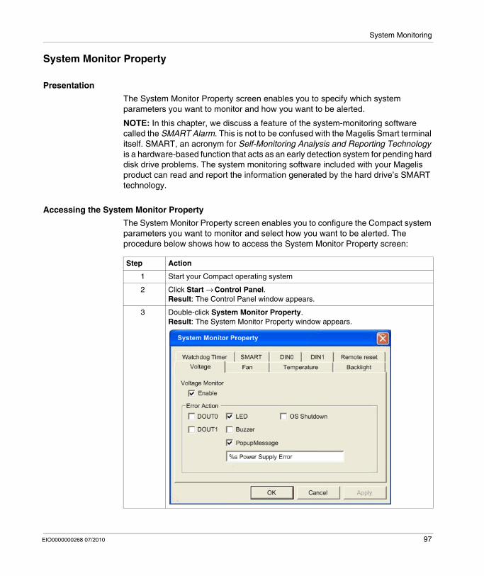
System Monitoring
System Monitor Property
Presentation
The System Monitor Property screen enables you to specify which system parameters you want to monitor and how you want to be alerted.
NOTE: In this chapter, we discuss a feature of the system-monitoring software called the SMART Alarm. This is not to be confused with the Magelis Smart terminal itself. SMART, an acronym for Self-Monitoring Analysis and Reporting Technology is a hardware-based function that acts as an early detection system for pending hard disk drive problems. The system monitoring software included with your Magelis product can read and report the information generated by the hard drive’s SMART technology.
Accessing the System Monitor Property
The System Monitor Property screen enables you to configure the Compact system parameters you want to monitor and select how you want to be alerted. The procedure below shows how to access the System Monitor Property screen:
Step Action
1 Start your Compact operating system
2 Click Start → Control Panel.Result: The Control Panel window appears.
3 Double-click System Monitor Property.Result: The System Monitor Property window appears.
EIO0000000268 07/2010 97

System Monitoring
Setting up the System Monitor Properties
The following figure gives an overview of the System Monitor Property setting screen.
Click the tabs on the top of the screen to access the configuration page of each system parameter.
The table below describes the system parameters available for monitoring:
Feature Functions Supervised
Voltage Monitors the status of the Compact’s built-in power supply and internal CPU power supply.
Fan Monitors the CPU cooling fan RPM speeds
Temperature Provides an alert when the temperature of the CPU or the overall system exceeds the defined limit.
98 EIO0000000268 07/2010

System Monitoring
NOTE: An administrator authentication is required to view or configure SMART monitoring.
A CF card does not support SMART and therefore the status of the CF card cannot be monitored.If a hard drive is to be upgraded or requires replacement, only use a hard drive provided by Schneider Electric. The Compact 12’’ device has not been tested with third-party hard drives.
Once you know the system parameters you want to monitor, you can specify actions that will be undertaken when an event (timeout, value out of range...) occurs. Set the action to be performed when a System Monitor/RAS event occurs by selecting the relevant check box.
Backlight Detects backlight alarms. When the backlight becomes inoperative, the power LED will flash orange/red (Refer to Compact Unit Description (see page 26)).
Watchdog Timer This feature monitors the performance of the CPU by writing the uptime count value for the CPU to the built-in programmable timer of the RAS and by periodically clearing the count value from the CPU. Errors are detected when the clearing of the count values from the CPU stops. This causes a timer overflow.
SMART Monitors the status of the hard drive. Detects degradation in hard disk performance and hard disk errors that may result in data loss or operating system corruption.
CAUTIONHARD DISK DAMAGE
A Self-Monitoring Analysis and Reporting Technology (SMART) Alarm indicates the potential for hard disk damage and data loss. If a SMART Alarm is received:
Remove the Compact device from service and back up all data on the hard driveDepending on the error, reinstall the operating system or replace the hard disk drive
Failure to follow these instructions can result in injury or equipment damage.
Feature Functions Supervised
EIO0000000268 07/2010 99

System Monitoring
The following table gives a description of the operations that can be performed:
Power LED Indicator
The three colors Power LED (Refer to Compact Unit Description - Front View (see page 26)) indicates the Compact system conditions. It is also a power ON/OFF indicator. The Power LED is located on the front face of the unit.
The Compact unit can send the following system status information to an external device:
NOTE: If the orange Power LED of the Compact is illuminated immediately after the power is turned ON, a Touch Panel Self-test Error may have occurred.
Item Action
Enable Select or deselect this option to enable/disable each monitoring feature.
Buzzer Sound an electronic beep (this option is automatically disabled when a checkmark is placed in the OS shutdown checkbox).
Popup Message Display error messages as popup messages. (The monitored item and description of the error are displayed).
Operating System Shutdown Shutdown the operating system. (The shutdown confirmation message is not displayed).
Operating System Restart Resets the hardware.
Power LED The Power LED lights orange for an RAS alarm.
DOUT0 to 1 Output from the RAS port.
Power LED Color System Status Output Condition
Green (Lit) Normal operation (Power is ON) None
Green (Blinking) System is NOT running (Soft OFF). Refer to Compact Unit Description - Front View (see page 26).
None
Orange (Lit) An RAS alarm has occurred Power LED is enabled via System Monitor Property
Touch Panel Self-Test Error None
Orange/Red (Blinking)
Backlight is not functioning None
Not Lit Power is OFF –
100 EIO0000000268 07/2010

System Monitoring
Features Availability
The following table lists the operating settings available for each feature:
O: Setting available - X: Setting not available
Feature Operation
Buzzer Popup Message OS Shutdown Reset LED DOUT0 to 3
Watchdog Timer
O O O O O O
Voltage O O O X O O
Fan O O O X O O
Temperature O O O X O O
Backlight O O X X O O
SMART O O X X O O
DIN0 to 1 O O O X O O
EIO0000000268 07/2010 101

System Monitoring
System Monitor Interface
Presentation
You can monitor the system status at any time using the System Monitor interface.
Description of the Interface
The following screen gives an overview of the System Monitor interface. Selecting each of the tabs displays the status of each item. When an error occurs, the color of the tab changes.
NOTE: Administrator rights are required to view and execute SMART monitoring. If someone logs on without administrator rights, nothing is displayed in the SMART item.
NOTE: On the SMART tab, monitored hard disk drives are designated by a device number of 0 or 1. The device number 0 indicates the master (primary) HDD while the number 1 indicates the slave drive.
102 EIO0000000268 07/2010

System Monitoring
The System Monitor interface displays the status of the system parameters. The following table describes the messages provided by the System Monitor interface:
NOTE: Not Supported is displayed when a device such as a Compact Flash card, which does not support SMART, is detected.
System Monitoring Operation
When an error is detected, the operations specified in the System Monitor Properties settings are performed (buzzer, popup message etc.) and an X is displayed on the icon in the system tray indicating an error status.
When the icon in the system tray changes as shown below, double-clicking the icon gives an explanation of the error condition.
The system performs the Error Action set in the System Monitor Properties when an error condition is detected with each monitoring item. The Error Action is performed only once when an error is detected for any of the items being monitored.
For example, look at the +3.3 V and +5.0 V options in the Voltage field. When the popup message feature for monitoring the voltage status is enabled, the popup message +3.3 V Power Supply Error is shown on the screen if a +3.3 V power supply error occurs. Press the OK button on the dialog box to hide the message.
Display Meaning
Pass Normal
Fail Abnormal (exceeds programmed limits)
Disabled Monitoring disabled
Not Supported Not supported
EIO0000000268 07/2010 103
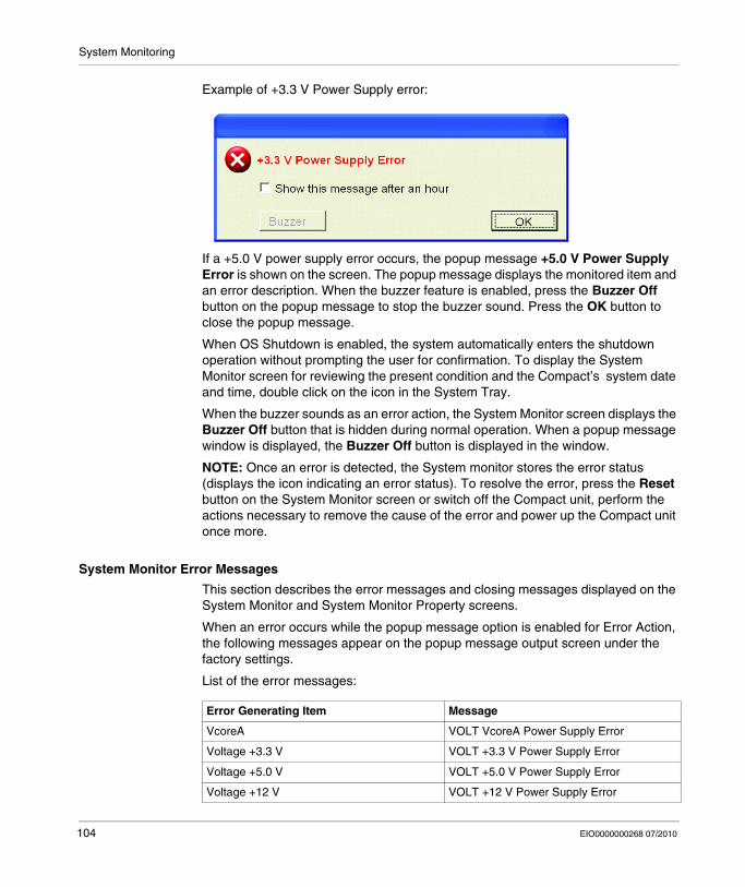
System Monitoring
Example of +3.3 V Power Supply error:
If a +5.0 V power supply error occurs, the popup message +5.0 V Power Supply Error is shown on the screen. The popup message displays the monitored item and an error description. When the buzzer feature is enabled, press the Buzzer Off button on the popup message to stop the buzzer sound. Press the OK button to close the popup message.
When OS Shutdown is enabled, the system automatically enters the shutdown operation without prompting the user for confirmation. To display the System Monitor screen for reviewing the present condition and the Compact’s system date and time, double click on the icon in the System Tray.
When the buzzer sounds as an error action, the System Monitor screen displays the Buzzer Off button that is hidden during normal operation. When a popup message window is displayed, the Buzzer Off button is displayed in the window.
NOTE: Once an error is detected, the System monitor stores the error status (displays the icon indicating an error status). To resolve the error, press the Reset button on the System Monitor screen or switch off the Compact unit, perform the actions necessary to remove the cause of the error and power up the Compact unit once more.
System Monitor Error Messages
This section describes the error messages and closing messages displayed on the System Monitor and System Monitor Property screens.
When an error occurs while the popup message option is enabled for Error Action, the following messages appear on the popup message output screen under the factory settings.
List of the error messages:
Error Generating Item Message
VcoreA VOLT VcoreA Power Supply Error
Voltage +3.3 V VOLT +3.3 V Power Supply Error
Voltage +5.0 V VOLT +5.0 V Power Supply Error
Voltage +12 V VOLT +12 V Power Supply Error
104 EIO0000000268 07/2010
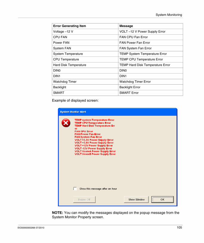
System Monitoring
Example of displayed screen:
NOTE: You can modify the messages displayed on the popup message from the System Monitor Property screen.
Voltage –12 V VOLT –12 V Power Supply Error
CPU FAN FAN CPU Fan Error
Power FAN FAN Power Fan Error
System FAN FAN System Fan Error
System Temperature TEMP System Temperature Error
CPU Temperature TEMP CPU Temperature Error
Hard Disk Temperature TEMP Hard Disk Temperature Error
DIN0 DIN0
DIN1 DIN1
Watchdog Timer Watchdog Timer Error
Backlight Backlight Error
SMART SMART Error
Error Generating Item Message
EIO0000000268 07/2010 105

System Monitoring
Error Displays when Using the Event Viewer
The System Log records error type/location and error actions as error events. You can check the error event information using the Event Viewer.
NOTE: This feature is supported by all versions of Windows® XP Pro, SP2 and above.
Error Type/Location and Error Action
The error type/locations shown by the Event Viewer are shown in the table below:
Step Action
1 Start your Compact terminal
2 Click Start → Control Panel → Administrative Tools → Event Viewer
Error type/Location Error Message Description
VcoreA VOLT VcoreA Error has occurred
Voltage +3.3 V VOLT +3.3 V Error has occurred
Voltage +5.0 V VOLT +5.0 V Error has occurred
Voltage +12 V VOLT +12 V Error has occurred
Voltage –12 V VOLT –12 V Error has occurred
CPU FAN FAN CPU Error has occurred
Power FAN FAN Power Error has occurred
System FAN FAN System Fan Error
System Temperature TEMP System Error has occurred
CPU Temperature TEMP CPU Error has occurred
Hard Disk Temperature TEMP Hard Disk Temperature Error
DIN0 DIN0 Error has occurred
DIN1 DIN1 Error has occurred
Watchdog Timer Watchdog Timer Error has occurred
Backlight Backlight Error has occurred
SMART SMART Error has occurred. Attribute (No.) (Attribute Name) Device (No.) (HD Model).The descriptions in parentheses vary depending on which error has occurred and which device it has occurred on. (0:Master, 1:Slave)
106 EIO0000000268 07/2010
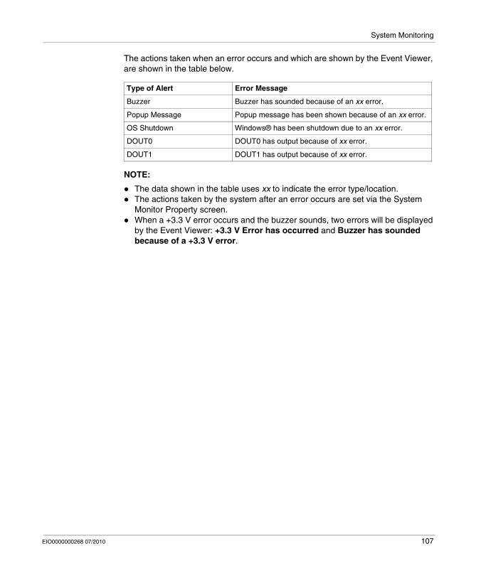
System Monitoring
The actions taken when an error occurs and which are shown by the Event Viewer, are shown in the table below.
NOTE:
The data shown in the table uses xx to indicate the error type/location.The actions taken by the system after an error occurs are set via the System Monitor Property screen.When a +3.3 V error occurs and the buzzer sounds, two errors will be displayed by the Event Viewer: +3.3 V Error has occurred and Buzzer has sounded because of a +3.3 V error.
Type of Alert Error Message
Buzzer Buzzer has sounded because of an xx error.
Popup Message Popup message has been shown because of an xx error.
OS Shutdown Windows® has been shutdown due to an xx error.
DOUT0 DOUT0 has output because of xx error.
DOUT1 DOUT1 has output because of xx error.
EIO0000000268 07/2010 107

System Monitoring
108 EIO0000000268 07/2010
EIO0000000268 07/2010
11
Maintenance
EIO0000000268 07/2010
Maintenance
Subject of this Chapter
This chapter covers maintenance of the Compact 12’’.
What's in this Chapter?
This chapter contains the following topics:
Topic Page
Reinstallation Procedure 110
Regular Cleaning and Maintenance 113
109

Maintenance
Reinstallation Procedure
At a Glance
In certain cases, it may be necessary to reinstall the operating system.
DANGERHAZARD OF ELECTRIC SHOCK, EXPLOSION, OR ARC FLASH
Remove all power from the device before removing any covers or elements of the system, and prior to installing or removing any accessories, hardware, or cables.Always use a properly rated voltage sensing device to confirm power is off.Unplug the power cable from both the Compact unit and the AC power supply.Replace and secure all covers or elements of the system before applying power to the unit.Use only the specified voltage when operating the Compact 12’’. This AC unit is designed to use 100...240 Vac input.
Failure to follow these instructions will result in death or serious injury.
DANGERCHEMICAL BURNS TO EYES OR SKIN
Do not use tools in the vicinity of the display or to operate the touch panel.When placing the display face-down, select a clean, level, non-abrasive surface. If necessary, place a soft, non-abrasive pad on the surface before lowering the unit.If a leak in the LCD panel is discovered and you come in contact with the liquid crystal material, follow these procedures:
In the case of contact with eyes or mouth, flush with running water for 15 minutes minimum.In the case of contact with skin or clothing, wipe off the liquid crystal material and wash with soap and running water for 15 minutes.If liquid crystal is ingested, induce vomiting, rinse mouth, and then drink a large quantity of water.Follow any other hazardous substances safety procedures required by your facility.
Failure to follow these instructions will result in death or serious injury.
110 EIO0000000268 07/2010

Maintenance
Precautions to be taken:
Keep static-producing materials (plastic, upholstery, carpeting) out of the immediate work area.Do not remove ESD-sensitive components from their anti-static bags until you are ready to install them.When handling static-sensitive components, wear a properly grounded wrist strap (or equivalent).Avoid unnecessary contact with exposed conductors and component leads with skin or clothing.
Before Reinstallation
Before reinstalling the operating system, make sure that the following equipment is at hand:
The restore CD-ROMs that were provided with the productAn external CD-ROM driveA USB keyboard.
NOTE: Save all important data on the hard drive or Compact Flash card (the reinstallation process erases all data on them). The reinstallation process will return the computer to its factory settings.
CAUTIONOVERTORQUE AND LOOSE HARDWARE
Do not exert more than 0.6 N•m (5.3 lb-in) of torque when tightening the installation fastener, enclosure, accessory, or terminal block screws. Tightening the screws with excessive force can damage the plastic casing of the Compact 12’’.When installing or removing screws, ensure that they do not fall inside the Compact 12’’ unit's chassis.
Failure to follow these instructions can result in injury or equipment damage.
CAUTIONSTATIC SENSITIVE COMPONENTS
Compact 12’’ internal components, including accessories such as RAM modules and expansion boards, can be damaged by static electricity. Observe the electrostatic precautions below when handling such components.
Failure to follow these instructions can result in equipment damage.
EIO0000000268 07/2010 111
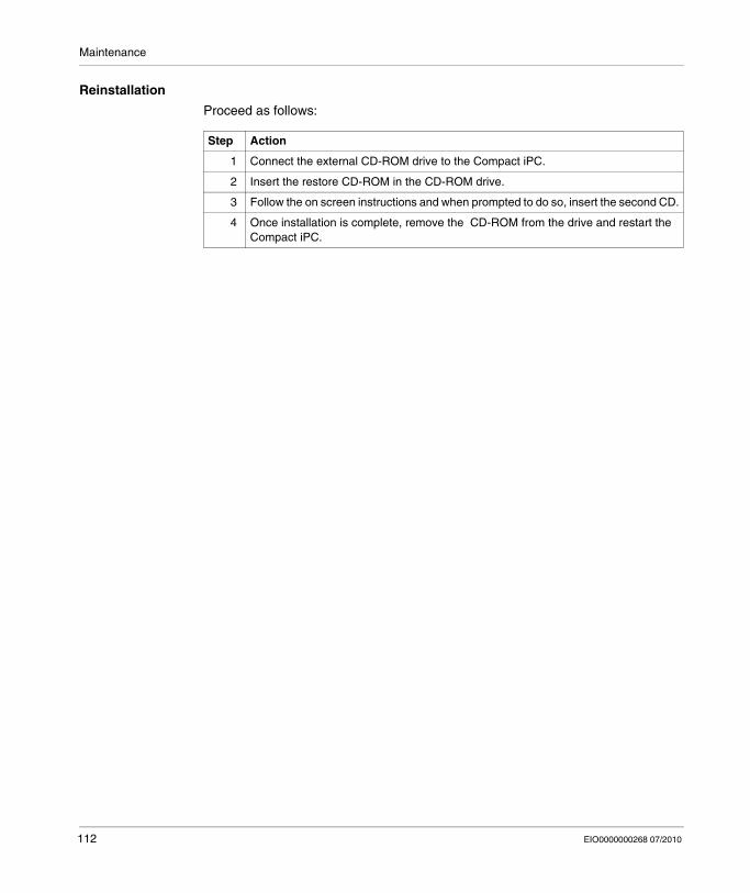
Maintenance
Reinstallation
Proceed as follows:
Step Action
1 Connect the external CD-ROM drive to the Compact iPC.
2 Insert the restore CD-ROM in the CD-ROM drive.
3 Follow the on screen instructions and when prompted to do so, insert the second CD.
4 Once installation is complete, remove the CD-ROM from the drive and restart the Compact iPC.
112 EIO0000000268 07/2010

Maintenance
Regular Cleaning and Maintenance
Cleaning Solutions
Removing and Cleaning the Fan Filter
Since excessive dirt and dust in the filter of the Compact’s electric fan can potentially affect the performance of the unit, regular inspection and cleaning of the filter is strongly recommended.
Cleaning the Fan Filter
CAUTIONHARMFUL CLEANING SOLUTIONS
Do not clean the unit or any component of the unit with paint thinner, organic solvents, or strong acids.Use only a mild soap or detergent that will not harm the polycarbonate material of the screen.
Failure to follow these instructions can result in injury or equipment damage.
DANGERHAZARD OF ELECTRIC SHOCK, EXPLOSION OR ARC FLASH
Read and understand the safety information on previous pages (Refer to Reinstal-lation procedure (see page 110)) before attempting this procedure.
Failure to follow these instructions will result in death or serious injury.
EIO0000000268 07/2010 113
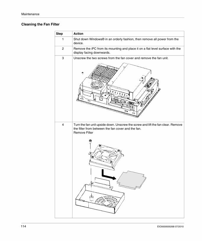
Maintenance
Cleaning the Fan Filter
Step Action
1 Shut down Windows® in an orderly fashion, then remove all power from the device.
2 Remove the iPC from its mounting and place it on a flat level surface with the display facing downwards.
3 Unscrew the two screws from the fan cover and remove the fan unit.
4 Turn the fan unit upside down. Unscrew the screw and lift the fan clear. Remove the filter from between the fan cover and the fan.Remove Filter
114 EIO0000000268 07/2010

Maintenance
5 Clean the filter completely. If stubborn dirt or stains are present, wash the filter with a neutral detergent.NOTE:
Do not wring the filter to dry it.When drying the filter, dry it without exposing it to direct sunlight.Allow it to air dry completely before reattaching to the Compact iPC.After replacing the filter to the filter cover, reattach the fan cover .
Filter Drying
6 Install the filter, replace the fan and tighten the screw on the fan cover.
7 Install the fan cover unit and tighten with the two screws. Ensure that the fan cover is securely attached to the Compact iPC unit.
Step Action
EIO0000000268 07/2010 115

Maintenance
Installing a Replacement Gasket
Installation Gasket
Use of the installation gasket may help extend the operating life of your Compact. The gasket is required to meet the protection ratings (IP65, IP20) of the unit and provides additional protection from vibration. Even if moisture protection is not required, install the gasket delivered with your Magelis product.
The corresponding gasket is provided in the maintenance kit ref: MPC YK 50 MNT KIT.
Installation Fasteners
NOTE: The screw installation fasteners are required for NEMA4 protection.
CAUTIONLOSS OF SEAL
Inspect the installation gasket prior to installation or reinstallation, and periodically as required by your operating environment.Replace the gasket if visible scratches, tears, dirt, or excessive wear are noted during inspection.Do not stretch the gasket unnecessarily or allow the gasket to contact the corners or edges of the frame.Ensure that the gasket is fully seated in the installation groove.Install the Compact into a panel that is flat and free of scratches or dents.Tighten the installation fasteners using a torque of 0.5 N•m (4.5 lb-in).
Failure to follow these instructions can result in injury or equipment damage.
CAUTIONOVERTORQUE AND LOOSE HARDWARE
Do not exert more than 0.6 N•m (5.3 lb-in) of torque when tightening the installation fastener, enclosure, accessory, or terminal block screws. Tightening the screws with excessive force can damage the plastic casing of the Compact 12’’. When installing or removing screws, ensure that they do not fall inside the Compact 12’’ unit's chassis.
Failure to follow these instructions can result in injury or equipment damage.
116 EIO0000000268 07/2010
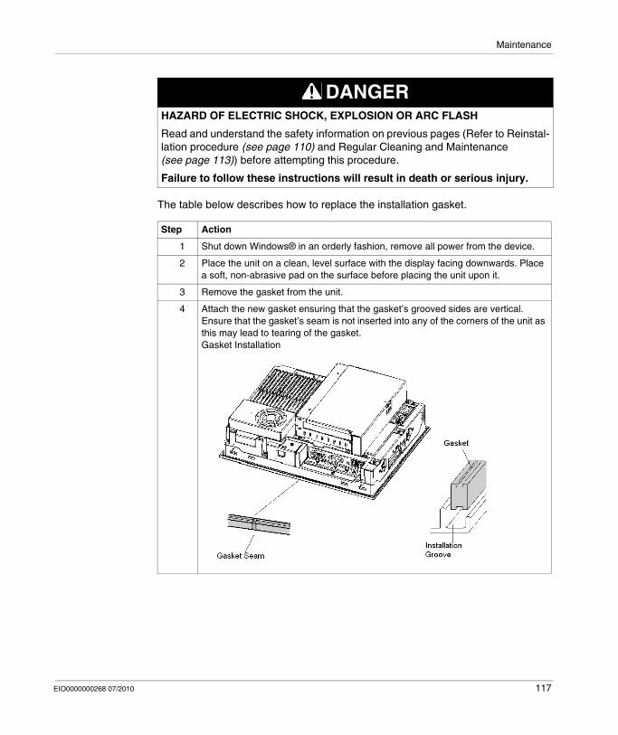
Maintenance
The table below describes how to replace the installation gasket.
DANGERHAZARD OF ELECTRIC SHOCK, EXPLOSION OR ARC FLASH
Read and understand the safety information on previous pages (Refer to Reinstal-lation procedure (see page 110) and Regular Cleaning and Maintenance (see page 113)) before attempting this procedure.
Failure to follow these instructions will result in death or serious injury.
Step Action
1 Shut down Windows® in an orderly fashion, remove all power from the device.
2 Place the unit on a clean, level surface with the display facing downwards. Place a soft, non-abrasive pad on the surface before placing the unit upon it.
3 Remove the gasket from the unit.
4 Attach the new gasket ensuring that the gasket’s grooved sides are vertical. Ensure that the gasket’s seam is not inserted into any of the corners of the unit as this may lead to tearing of the gasket. Gasket Installation
EIO0000000268 07/2010 117
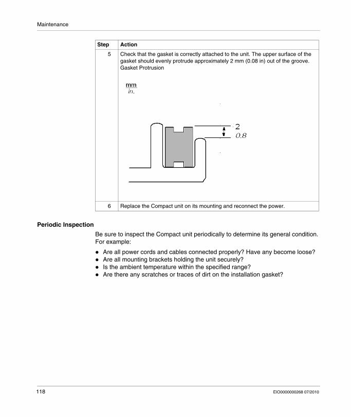
Maintenance
Periodic Inspection
Be sure to inspect the Compact unit periodically to determine its general condition. For example:
Are all power cords and cables connected properly? Have any become loose?Are all mounting brackets holding the unit securely?Is the ambient temperature within the specified range?Are there any scratches or traces of dirt on the installation gasket?
5 Check that the gasket is correctly attached to the unit. The upper surface of the gasket should evenly protrude approximately 2 mm (0.08 in) out of the groove.Gasket Protrusion
6 Replace the Compact unit on its mounting and reconnect the power.
Step Action
118 EIO0000000268 07/2010
EIO0000000268 07/2010
12
Troubleshooting
EIO0000000268 07/2010
Troubleshooting
Troubleshooting
Troubleshooting Checklist
This section explains how to find and resolve troubleshooting items with the Compact unit.
The Compact can be connected to a wide range of devices, including a host (PLC), however, this manual will not discuss every possible device or condition. For problems not directly related to the Compact unit, refer to that device’s manual.
The most likely items for troubleshooting that can occur during usage of the Compact are:
The Touch Panel display is blankThe Touch Panel does not respondConnected devices cannot be used.
When one occurs, be sure to first read each checklist item and follow the instructions given. If this does not solve the problem, please contact your local Compact distributor.
When a hardware or software issue occurs that you cannot resolve, please contact the distributor where you purchased the Compact unit.
No Display
Step Check Item or Operation Check Result
Action Required
1 Switch OFF the Compact power supply.
2 Is the power cord connected correctly?
Connect the power cord correctly.
3 Is the power supply voltage within specification?
Please refer to Power Supply (see page 33).
4 Switch ON the power supply.
119
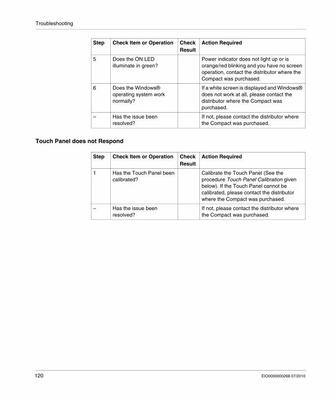
Troubleshooting
Touch Panel does not Respond
5 Does the ON LED illuminate in green?
Power indicator does not light up or is orange/red blinking and you have no screen operation, contact the distributor where the Compact was purchased.
6 Does the Windows® operating system work normally?
If a white screen is displayed and Windows® does not work at all, please contact the distributor where the Compact was purchased.
– Has the issue been resolved?
If not, please contact the distributor where the Compact was purchased.
Step Check Item or Operation Check Result
Action Required
Step Check Item or Operation Check Result
Action Required
1 Has the Touch Panel been calibrated?
Calibrate the Touch Panel (See the procedure Touch Panel Calibration given below). If the Touch Panel cannot be calibrated, please contact the distributor where the Compact was purchased.
– Has the issue been resolved?
If not, please contact the distributor where the Compact was purchased.
120 EIO0000000268 07/2010
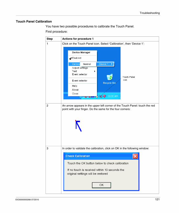
Troubleshooting
Touch Panel Calibration
You have two possible procedures to calibrate the Touch Panel.
First procedure:
Step Actions for procedure 1
1 Click on the Touch Panel icon. Select ‘Calibration’, then ‘Device 1’:
2 An arrow appears in the upper left corner of the Touch Panel: touch the red point with your finger. Do the same for the four corners:
3 In order to validate the calibration, click on OK in the following window:
EIO0000000268 07/2010 121
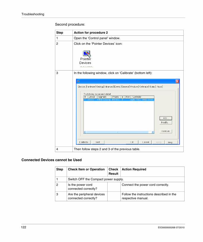
Troubleshooting
Second procedure:
Connected Devices cannot be Used
Step Action for procedure 2
1 Open the ‘Control panel’ window.
2 Click on the ‘Pointer Devices’ icon:
3 In the following window, click on ‘Calibrate’ (bottom left):
4 Then follow steps 2 and 3 of the previous table.
Step Check Item or Operation Check Result
Action Required
1 Switch OFF the Compact power supply.
2 Is the power cord connected correctly?
Connect the power cord correctly.
3 Are the peripheral devices connected correctly?
Follow the instructions described in the respective manual.
122 EIO0000000268 07/2010

Troubleshooting
Recovery
Please refer to the reinstallation procedure. Refer to Reinstallation Procedure (see page 110).
4 Switch ON the Compact power supply.
5 Does this device require driver setup?
Refer to the device’s manual and setup the driver.
– Has the issue been resolved?
If not, please contact the distributor where the Compact was purchased.
Step Check Item or Operation Check Result
Action Required
EIO0000000268 07/2010 123

Troubleshooting
124 EIO0000000268 07/2010
EIO0000000268 07/2010
IV
Appendices
EIO0000000268 07/2010
Appendices
125

Appendices
126 EIO0000000268 07/2010

EIO0000000268 07/2010
13
Accessories
EIO0000000268 07/2010
Accessories
Accessories for the Compact 12’’
List
Accessories are available as options. The list of accessories available for the Compact 12’’ is shown below:
Description Reference
RAM 1 GB MPC YK22 RA 1024
Compact Flash 1 GB - Blank MPC YN00 CF1 00N
Compact Flash 2 GB - Blank MPC YN00 CF2 00N
Compact Flash 4 GB - Blank MPC YN00 CF4 00N
Maintenance Kit including installation fasteners, installation screws and gasket
MPC YK20 MNT KIT
Protection sheet MPC YK20 SPS KIT
Removable hard disk ≥ 80 GB for Compact 12’’ level 2.To be used with restore tool delivered with every compact 12’’ level 2.
MPC YNK2 SHD 20N
Removable solid state disk ≥ 16 GB for Compact level 2.To be used with restore tool delivered with every compact level 2.
MPC YNK2 MSD 20N
Removable STD hard disk for compact MPC YNK2 SHD 20N
Removable medium SSD for compact MPC YNK2 MSD 20N
127

Accessories
128 EIO0000000268 07/2010
Index
EIO0000000268 07/2010
CBA
IndexAAccessing the BIOS, 59Accessories for the Compact 12’’, 127
BBefore Modifications, 64
CCharacteristics, 34Characteristics of the Compact 12’’, 32Cleaning and Maintenance, 113Cleaning the Fan Filter, 113, 114Compact Flash (CF) Card Installation and Removal, 73Compact Unit Description, 26Connecting the AC Power Cord, 57Connection to PLCs, 85
Cables and Converters, 88Traditional Architectures, 86Transparent Ready Architectures, 85
Creating a Panel Cut-Out for Cabinet Instal-lation, 41
DData Writing Limitation, 75Dedicated Ground, 54Dimensions, 38Dimensions of the Compact iPC Unit, 38Dimensions with Installation Fasteners, 40
EIO0000000268 07/2010
Display Characteristics, 33
EEnvironmental Characteristics, 35Exit BIOS saving the Modifications, 62Exit BIOS Without Saving Modifications, 62Expansion Board (PCI) Installation, 68Extended Memory, 60
FFlash Disk (SSD) Characteristics, 34
GGrounding, 54
HHard Disk Drive (HDD) Unit Installation, 79
IInserting the CF Card, 74Installation Fasteners Dimensions, 39Installation Gasket, 44Installation Location, 41Installing a Replacement Gasket, 116
129

Index
Installing the Compact Unit, 45Installing the Expansion Board, 68Installing the PCMCIA Card, 71Items, 24
MMain Menu, 59
OOperating Systems, 33
PPackage Contents, 24Panel Cut Dimensions, 42Panel Mounting, 41Password Security, 61PCMCIA Card Installation, 70Periodic Inspection, 118Power Supply, 33Preparing to Install the 12’’ Compact, 43Preparing to Use a CF Card, 73Primary Master, 60Primary Slave, 60Product Characteristics, 32
RReinstallation Procedure, 110Removing a Type III PCMCIA Card, 72Removing the CF Card, 75
SShared Ground - Avoid Ground Loop, 55Shared Ground Allowed, 55Shared Ground not Allowed , 55Supervisor Password, 61System Date, 60System Memory, 60
130
System Monitor access, 97 configuration, 97access, 96interface, 102overview, 90
System Monitor Property, 97System Time, 60
UUSB Holder Attachment, 77USB Holder Attachment/Removal, 76USB Holder Removal, 78Useful Tools, 52User Password, 62
VVibration and Shocks, 43
EIO0000000268 07/2010


![HMIs and Industrial PCs [PDF, 3.67 MB]](https://img.pdfslide.us/doc/110x75/586b6ade1a28abb7768bd293/hmis-and-industrial-pcs-pdf-367-mb.jpg)