Embed Size (px)
Citation preview
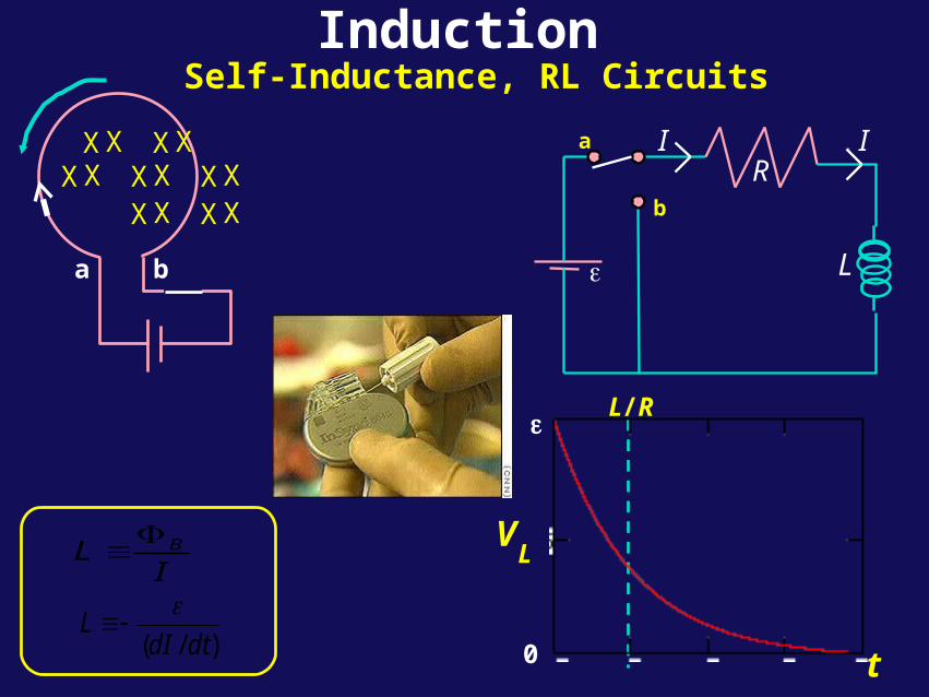
InductionSelf-Inductance, RL Circuits
V
t0
L
IL B
)/( dtdIL
L/R
RI
a
b
L
IX X X X X X X
X X X X X X X
a b
Today...• Mutual Inductance – applications!
• Concept of Self-Inductance
• Definition of Self-Inductance
• Calculation of Self-Inductance for Simple Cases
• RL Circuits
• Energy in Magnetic Field
Mutual Inductance
ab
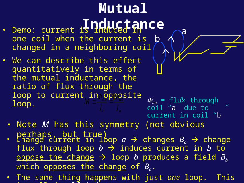
• Demo: current is induced in one coil when the current is changed in a neighboring coil
• We can describe this effect quantitatively in terms of the mutual inductance, the ratio of flux through the loop to current in opposite loop.
• Note M has this symmetry (not obvious perhaps, but true)
• Change current in loop a changes Ba change flux through loop b induces current in b to oppose the change loop b produces a field Bb which opposes the change of Ba.
• The same thing happens with just one loop. This is called self-inductance.
a
ba
b
ab
IIM
ab = flux through coil “a”
due to current in coil “b”
Applications of Mutual Inductance
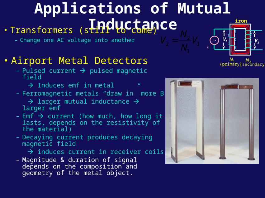
• Transformers (still to come)– Change one AC voltage into another
(primary) (secondary)
N2N1
iron
V2V1
22 1
1
NV V
N
• Airport Metal Detectors– Pulsed current pulsed magnetic field Induces emf in metal– Ferromagnetic metals “draw in” more B larger mutual inductance larger emf– Emf current (how much, how long it
lasts, depends on the resistivity of the material)
– Decaying current produces decaying magnetic field
induces current in receiver coils– Magnitude & duration of signal depends
on the composition and geometry of the metal object.
Applications of Mutual Inductance
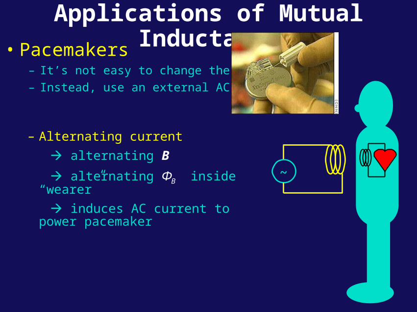
• Pacemakers– It’s not easy to change the battery!
– Instead, use an external AC supply.
~
– Alternating current
alternating B
alternating ФB inside “wearer”
induces AC current to power pacemaker

Applications of Mutual Inductance
Self-Inductance
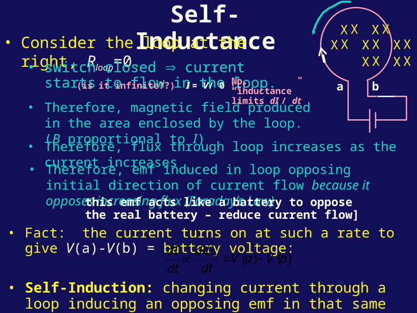
• Self-Induction: changing current through a loop inducing an opposing emf in that same loop.
• Therefore, magnetic field produced in the area enclosed by the loop. (B proportional to I)
• Therefore, flux through loop increases as the current increases
X X X X X X X
X X X X X X X
a b
• Therefore, emf induced in loop opposing initial direction of current flow because it opposes increasing flux (Faraday’s Law) this emf acts like a battery to oppose
the real battery – reduce current flow]
• Fact: the current turns on at such a rate to give V(a)-V(b) = battery voltage:
)()( bVaVdt
d
dt
dI B
• Consider the loop at the right, Rloop=0.
• switch closed current starts to flow in the loop. (is it infinite??) I = V/ 0 !!! No. “inductance”
limits dI / dt
Self-Inductance
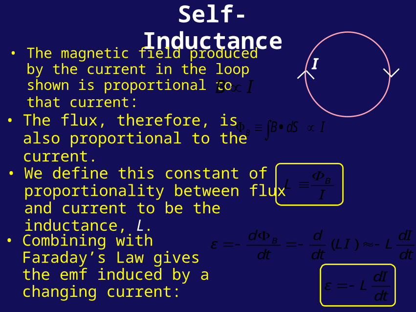
• Combining with Faraday’s Law gives the emf induced by a changing current:
• The flux, therefore, is also proportional to the current. B B dS I
I• The magnetic field produced by the
current in the loop shown is proportional to that current: IB
• We define this constant of proportionality between flux and current to be the inductance, L.
IL B
( )Bd d dIε LI L
dt dt dt
dIε L
dt
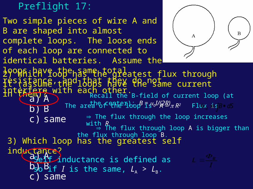
Two simple pieces of wire A and B are shaped into almost complete loops. The loose ends of each loop are connected to identical batteries. Assume the loops have the same total resistance, and that they do not interfere with each other.
3) Which loop has the greatest self inductance?
2) Which loop has the greatest flux through it (assume the loops have the same current in them)?
Preflight 17:
a) Ab) Bc) same
a) Ab) Bc) same
Self inductance is defined as so if I is the same, LA > LB.
IL B
Recall the B-field of current loop (at the center): B = 0I/(2R)
The area of the loop is A = R2 Flux is
The flux through the loop increases with R. SdBB
The flux through loop A is bigger than the flux through loop B.
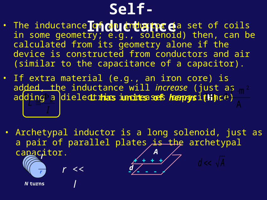
Self-Inductance• The inductance of an inductor (a set of coils in some geometry;
e.g., solenoid) then, can be calculated from its geometry alone if the device is constructed from conductors and air (similar to the capacitance of a capacitor).
• If extra material (e.g., an iron core) is added, the inductance will increase (just as adding a dielectric increases capacitance)
• Archetypal inductor is a long solenoid, just as a pair of parallel plates is the archetypal capacitor.
d
A
- - - - -
+ + + + d Ar << l
l
r
N turns
IL B
L has units of henrys (H):2T m
1 H 1A
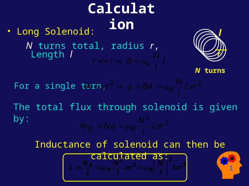
Calculation
l
r
N turns
• Long Solenoid:
N turns total, radius r, Length l
Il
NBlr 0
For a single turn, 20
2 rIl
NBArA
The total flux through solenoid is given by:
22
0 rIl
NNB
Inductance of solenoid can then be calculated as:
22
02
2
0 rll
Nr
l
N
IL B
1
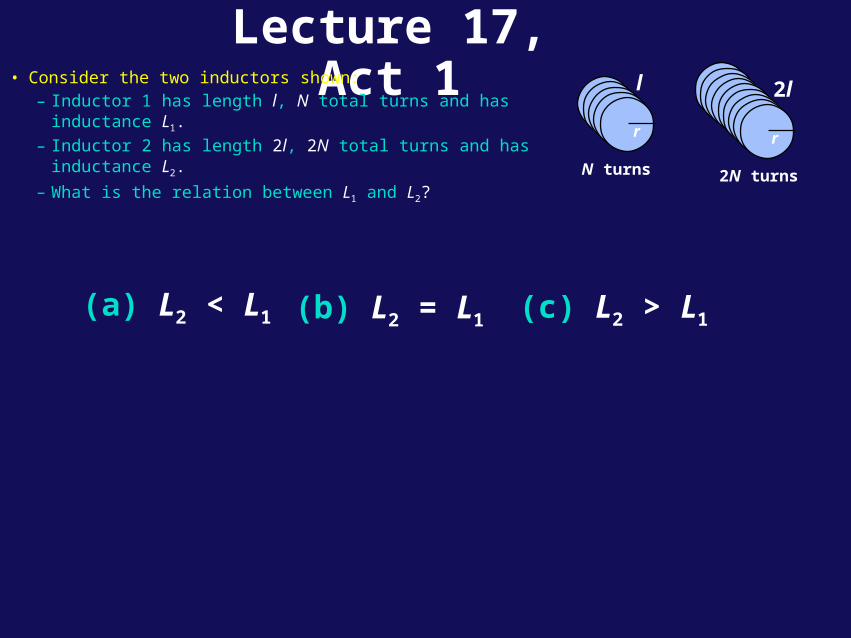
Lecture 17, Act 1• Consider the two inductors shown:
– Inductor 1 has length l, N total turns and has inductance L1.
– Inductor 2 has length 2l, 2N total turns and has inductance L2.
– What is the relation between L1 and L2?
(a) L2 < L1 (b) L2 = L1 (c) L2 > L1
l
r
N turns
r2l
r
2N turns
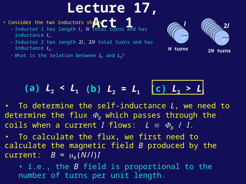
Lecture 17, Act 1
(a) L2 < L1 (b) L2 = L1 (c) L2 > L1
• To determine the self-inductance L, we need to determine the flux B which passes through the coils when a current I flows: L B / I.
• To calculate the flux, we first need to calculate the magnetic field B produced by the current: B = 0(N/l)I
• i.e., the B field is proportional to the number of turns per unit length.
• Therefore, B1 = B2. But does that mean L1 = L2?
l
r
N turns
r2l
r
2N turns
• Consider the two inductors shown:
– Inductor 1 has length l, N total turns and has inductance L1.
– Inductor 2 has length 2l, 2N total turns and has inductance L2.
– What is the relation between L1 and L2?
Lecture 17, Act 1
l
r
N turns
r2l
r
2N turns
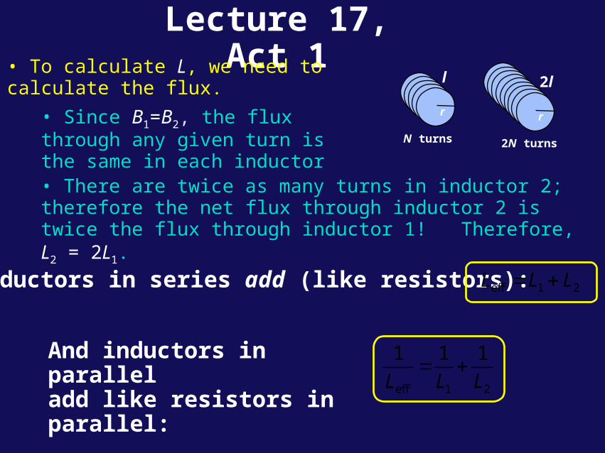
• To calculate L, we need to calculate the flux.
• Since B1=B2, the flux through any given turn is the same in each inductor• There are twice as many turns in inductor 2; therefore the net flux through inductor 2 is twice the flux through inductor 1! Therefore, L2 = 2L1.
Inductors in series add (like resistors): eff 1 2L L L
And inductors in parallel add like resistors in parallel:
eff 1 2
1 1 1
L L L
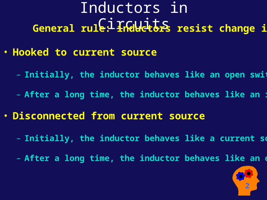
Inductors in Circuits General rule: inductors resist change in current
• Hooked to current source
– Initially, the inductor behaves like an open switch.
– After a long time, the inductor behaves like an ideal wire.
• Disconnected from current source
– Initially, the inductor behaves like a current source.
– After a long time, the inductor behaves like an open switch.
2
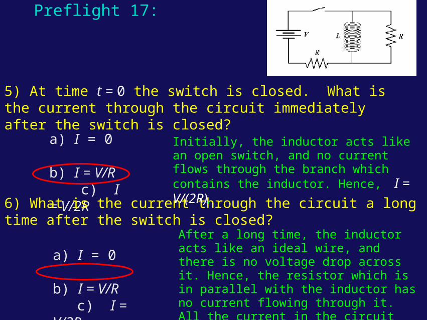
5) At time t = 0 the switch is closed. What is the current through the circuit immediately after the switch is closed?
a) I = 0 b) I = V/R c) I = V/2R
6) What is the current through the circuit a long time after the switch is closed?
a) I = 0 b) I = V/R c) I = V/2R
Preflight 17:
Initially, the inductor acts like an open switch, and no current flows through the branch which contains the inductor. Hence, I = V/(2R).
After a long time, the inductor acts like an ideal wire, and there is no voltage drop across it. Hence, the resistor which is in parallel with the inductor has no current flowing through it. All the current in the circuit flows through the inductor, and
I = V/R.
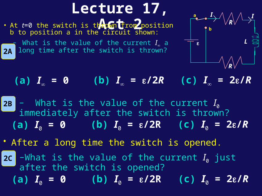
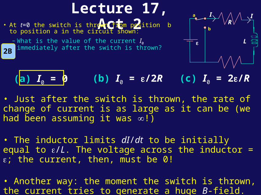
Lecture 17, Act 2• At t=0 the switch is thrown from position b to
position a in the circuit shown:
– What is the value of the current I a long time after the switch is thrown?
(a) I = 0 (b) I = /2R (c) I = 2/R
(a) I0 = 0 (b) I0 = /2R (c) I0 = 2/R
2A
– What is the value of the current I0 immediately after the switch is thrown?
2B
R
a
b
R
L
II
(a) I0 = 0 (b) I0 = /2R (c) I0 = 2/R
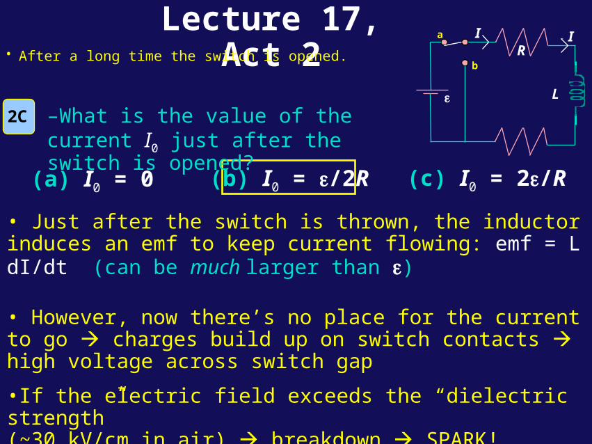
–What is the value of the current I0 just after the switch is opened?
2C
• After a long time the switch is opened.
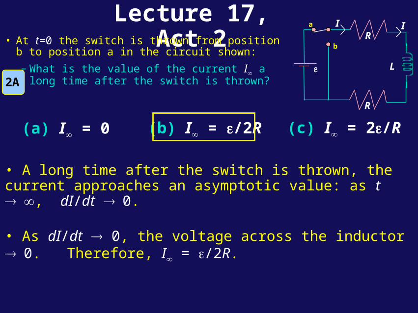
Lecture 17, Act 2
(a) I = 0 (b) I = /2R (c) I = 2/R
2A
• A long time after the switch is thrown, the current approaches an asymptotic value: as t , dI/dt 0.
• As dI/dt 0, the voltage across the inductor 0. Therefore, I = /2R.
• At t=0 the switch is thrown from position b to position a in the circuit shown:
– What is the value of the current I a long time after the switch is thrown?
a
b
R
L
II
R
Lecture 17, Act 2• At t=0 the switch is thrown from position b to
position a in the circuit shown:
– What is the value of the current I0 immediately after the switch is thrown?
(a) I0 = 0 (b) I0 = /2R (c) I0 = 2/R
2B
• Just after the switch is thrown, the rate of change of current is as large as it can be (we had been assuming it was !)
• The inductor limits dI/dt to be initially equal to /L. The voltage across the inductor = ; the current, then, must be 0!
• Another way: the moment the switch is thrown, the current tries to generate a huge B-field. There is a huge change in flux through coil—an emf is generated to oppose this. Initially, then, no current flows through no voltage drop across the resistors.
a
b
R
L
II
Lecture 17, Act 2
(a) I0 = 0 (b) I0 = /2R (c) I0 = 2/R
2C
• Just after the switch is thrown, the inductor induces an emf to keep current flowing: emf = L dI/dt (can be much larger than )
• However, now there’s no place for the current to go charges build up on switch contacts high voltage across switch gap
•If the electric field exceeds the “dielectric strength” (~30 kV/cm in air) breakdown SPARK!
This phenomenon is used in “flyback generators” to create high voltages; it also destroys lots of electronic equipment!
a
b
R
L
II
• After a long time the switch is opened.
–What is the value of the current I0 just after the switch is opened?
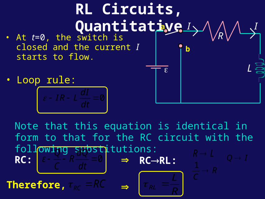
RL Circuits, Quantitative
• At t=0, the switch is closed and the current I starts to flow.
Note that this equation is identical in form to that for the RC circuit with the following substitutions:
RI
a
b
L
I
• Loop rule:
0dI
IR Ldt
Therefore, RCRC R
LRL
RC: 0Q dQ
ε RC dt
RCRL: LR
RC
1
IQ
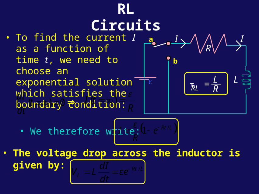
RL Circuits
• To find the current I as a function of time t, we need to choose an exponential solution which satisfies the boundary condition:
0)( tdt
dIR
tI
)(
• We therefore write: LRteR
εI /1
• The voltage drop across the inductor is given by:
LRtL εe
dt
dILV /
R
RL = LR
a
b
L
I I
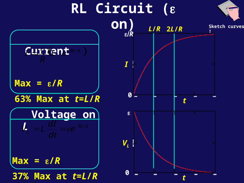
RL Circuit ( on)
Current
Max = /R
63% Max at t=L/R
LRteR
I /1
L/R
t
I
2L/R
0
R
VL
0t
Voltage on L
Max = /R
37% Max at t=L/R
LRtL e
dt
dILV /
Sketch curves !
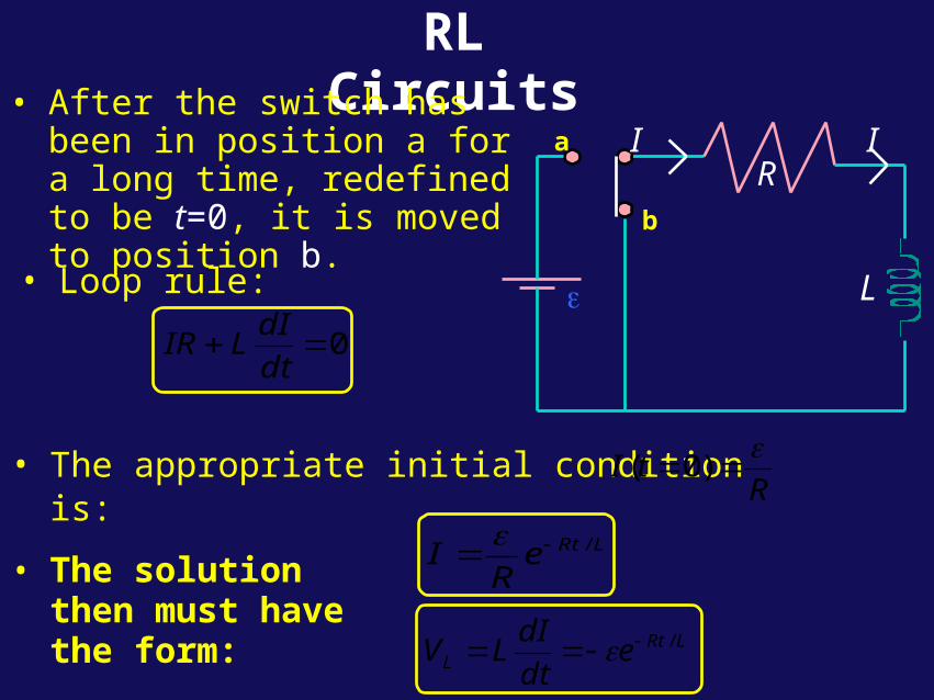
RL Circuits• After the switch has been in
position a for a long time, redefined to be t=0, it is moved to position b.
R
a
b
L
I I
• Loop rule:
0dt
dILIR
• The appropriate initial condition is:R
tI
)0(
• The solution then must have the form:
LRteR
I /
LRtL e
dt
dILV /
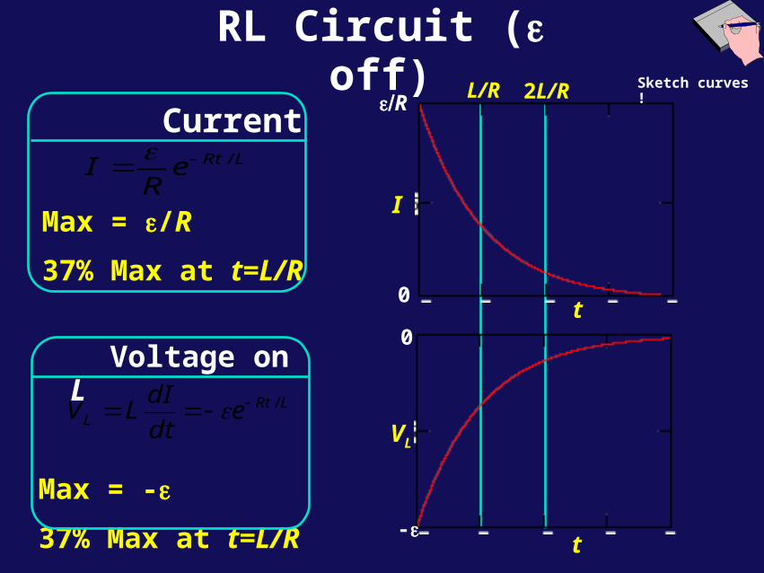
RL Circuit ( off)
0
-
VL
t
L/R
t
2L/R
I
0
R Current
Max = /R
37% Max at t=L/R
LRteR
I /
Voltage on L
Max = -
37% Max at t=L/R
LRtL e
dt
dILV /
Sketch curves !
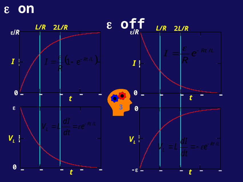
on off
t
0
-
I
t
0
R L/R 2L/R
LRteR
I /
LRtL e
dt
dILV /
VL
L/R
t
2L/R
0
R
I
0t
LRteR
I /1
LRtL e
dt
dILV /
VL
3
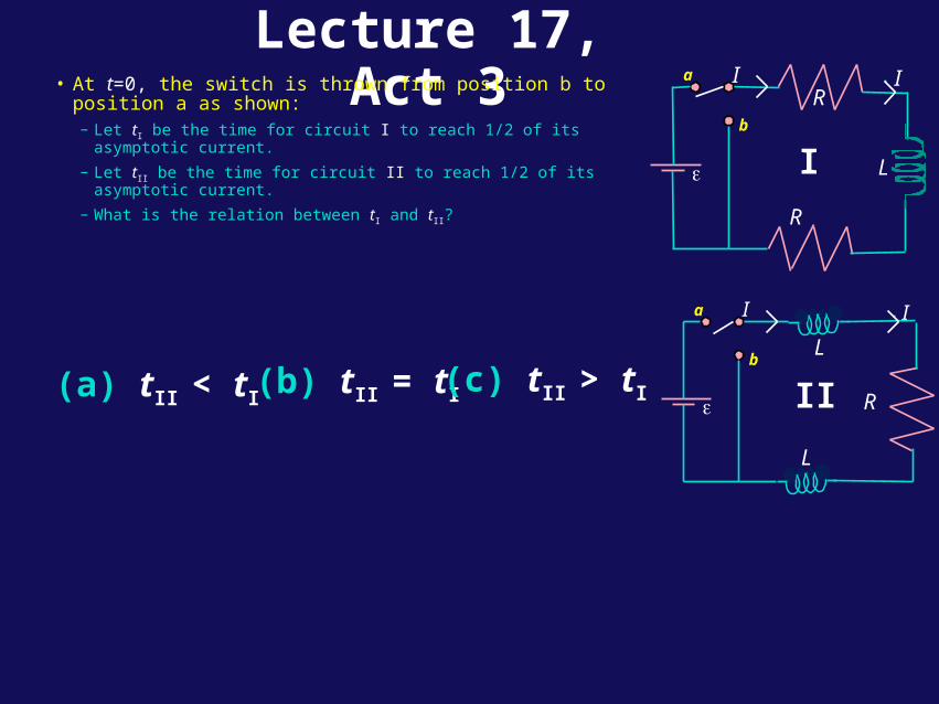
Lecture 17, Act 3• At t=0, the switch is thrown from position b to position a as
shown:– Let tI be the time for circuit I to reach 1/2 of its asymptotic current.
– Let tII be the time for circuit II to reach 1/2 of its asymptotic current.
– What is the relation between tI and tII?
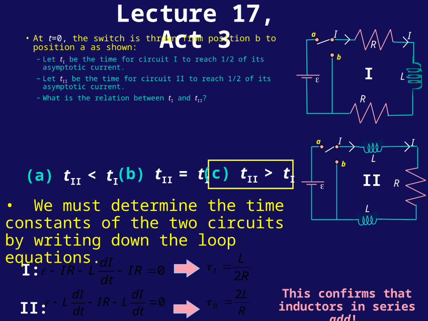
(a) tII < tI(b) tII = tI (c) tII > tI
a
bL
I I
R
L
II
IR
a
b
L
I
R
I
Lecture 17, Act 3
• We must determine the time constants of the two circuits by writing down the loop equations.
0dI
IR L IRdt
0dI dI
L IR Ldt dt
I:
II:
R
LI 2
R
LII
2
This confirms that inductors in series add!
(a) tII < tI(b) tII = tI (c) tII > tI
• At t=0, the switch is thrown from position b to position a as shown:– Let tI be the time for circuit I to reach 1/2 of its asymptotic current.
– Let tII be the time for circuit II to reach 1/2 of its asymptotic current.
– What is the relation between tI and tII?
a
bL
I I
R
L
II
IR
a
b
L
I
R
I
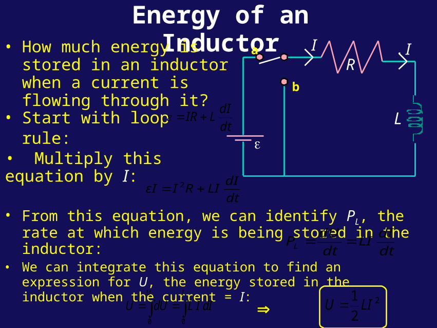
Energy of an Inductor• How much energy is stored
in an inductor when a current is flowing through it?
R
a
b
L
I I
• Start with loop rule:dt
dILIR
• From this equation, we can identify PL, the rate at which energy is being stored in the inductor:
dt
dILI
dt
dUPL
• We can integrate this equation to find an expression for U, the energy stored in the inductor when the current = I:
0 0
U I
U dU L I dI 2
2
1LIU
dt
dILIRIεI 2
• Multiply this equation by I:
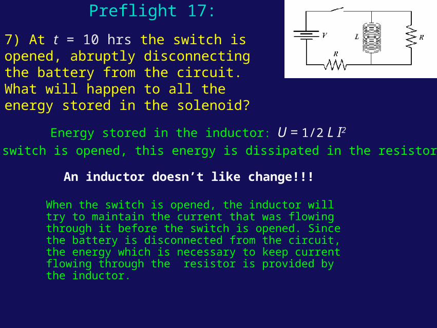
7) At t = 10 hrs the switch is opened, abruptly disconnecting the battery from the circuit. What will happen to all the energy stored in the solenoid?
Preflight 17:
Energy stored in the inductor: U = 1/2 L I2
An inductor doesn’t like change!!!
When the switch is opened, this energy is dissipated in the resistor.
When the switch is opened, the inductor will try to maintain the current that was flowing through it before the switch is opened. Since the battery is disconnected from the circuit, the energy which is necessary to keep current flowing through the resistor is provided by the inductor.
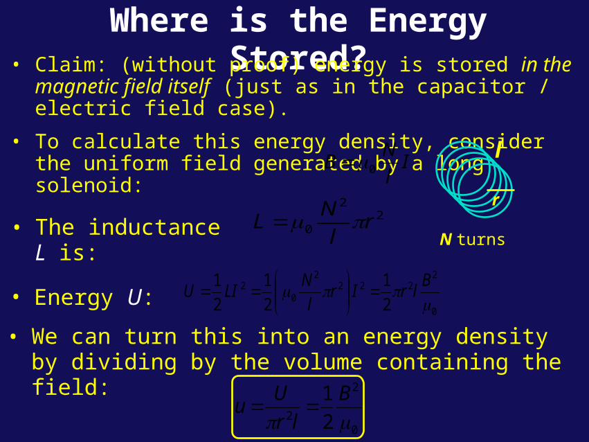
Where is the Energy Stored?• Claim: (without proof) energy is stored in the magnetic field
itself (just as in the capacitor / electric field case).
• To calculate this energy density, consider the uniform field generated by a long solenoid:
• The inductance L is:2
2
0 rl
NL
• Energy U:0
2222
2
02
2
1
2
1
2
1
B
lrIrl
NLIU
• We can turn this into an energy density by dividing by the volume containing the field:
0
2
2 2
1
B
lr
Uu
Il
NB 0 l
r
N turns
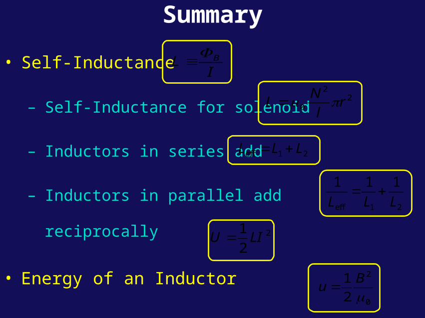
Summary
• Self-Inductance
– Self-Inductance for solenoid
– Inductors in series add
– Inductors in parallel add reciprocally
• Energy of an Inductor
• Energy stored in the Magnetic Field
IL B
22
0 rl
NL
2
2
1LIU
0
2
2
1
B
u
eff 1 2L L L
eff 1 2
1 1 1
L L L


![n}l·s :d/0f;rL s[lif - Asian Development Bank · n}l·s :d/0f;"rL s[lif o; b:t.a]h c+u|]hLaf6 cg'jfb u/L j[xt\ hg;d'bfodf hfgsf/L xf];\ eGg] x]t'n] k|sflzt ul/Psf] 5 ... f]t–;fwgdf](https://img.pdfslide.us/doc/110x75/5b8a543c7f8b9ac1328beb82/nls-d0frl-slif-asian-development-bank-nls-d0frl-slif-o-btah.jpg)
![· 2016-12-23635.04306 m)/Subtype/RL/Type/Measure/X[> >]>>/Type/Viewport>> > >]/D[> >]/R(\(in X\) 1 in = 635.03104 m : \(in Y\) 1 in = 635.04306 m)/Subtype/RL/Type/Measure/X[> >]>>/Type/Viewport>>](https://img.pdfslide.us/doc/110x75/5ae065197f8b9a6e5c8d530c/msubtyperltypemeasurex-typeviewport-d-rin-x-1-in-63503104.jpg)