Embed Size (px)
Citation preview

INDOT|BRIDGE DESIGN AIDS BDA 100‐02 | JANUARY 10, 2020 (REV. MAY 20, 2020)
Page | 1
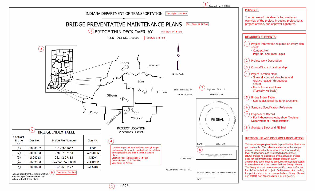
BRIDGE SAMPLE PLANS – BRIDGE THIN DECK OVERLAY
Reference: IDM 14‐2.05 Bridge Plans, Preservation Project
IDM 412‐2.01 Preventative Maintenance Project
BDA 412‐01 Patching Quantities for Polymeric Overlays
BDA 412‐03 Polymeric Overlay Project Considerations
The following set of sample bridge plans has been developed to illustrate a typical set of Bridge
Thin Deck Overlay plans. The tables throughout this set of sample plans have been generated
using the Excel spreadsheet Tables for Bridge PM Thin Deck Overlay.xlsm. Instructions for using
this spreadsheet are provided on the Instructions tab within the file.
The plans were revised May 20, 2020 for minor editorial changes, and to remove the thin deck
overlay from the reinforced bridge approach slab on several of the bridges. INDOT has noticed
a relatively high percentage of failures of thin deck overlays on reinforced bridge approach
slabs, and Construction Memo 20‐08 published on May 11, 2020 has directed Designers and
Construction to prohibit this application.
DATE:
PLANS PREPARED BY:
CERTIFIED BY:
INDIANA DEPARTMENT OF TRANSPORTATION
INDIANA DEPARTMENT OF TRANSPORTATION
PHONE NUMBER:
DATE
$SIG_DT$
of
Contract No:
BRIDGE PREVENTATIVE MAINTENANCE PLANS
PE SEAL
317-555-1234
Engineer of Record
2
3
4
7
6
1
A CERTIFIED DOCUMENT."
"THIS MEDIA SHOULD NOT BE CONSIDERED
2020
to be used with these plans.
Standard Specifications dated
Indiana Department of Transportation
B-00000
project location, and approval signatures.
overview of the project, including project data,
The purpose of this sheet is to provide an
PURPOSE:
1 1 25
and INDOT CAD Standards Manual will govern.
the policies stated in the current Indiana Design Manual
for his/her individual project. In the event of a conflict,
The Designer must determine specific content of notes
in accordance with the current Indiana Design Manual.
attempt has been made to produce a reasonable design
used for this hypothetical project although every
INDOT makes no guarantee of the accuracy of data
level of specificity, and its expected appearance.
plan are intended only to show a need for a callout,
purposes only. The callouts and notes in this sample
This set of sample plan sheets is provided for illustrative
INTENDED USE AND DISCLAIMER INFORMATION:
Not to Scale
Vincennes District
PROJECT LOCATION
RECOMMENDED FOR LETTING:
BRIDGE THIN DECK OVERLAY
Posey
Gibson
Vanderburg
h
Warrick
Pike
KnoxDaviess
Dubois
CONTRACT NO. B-00000
8
5
2
3
1
4
5
Signature Block and PE Seal 8
Department of Transportation"
- For in-house projects, show "Indiana
Engineer of Record 7
Standard Specification Reference 6
- See Tables Excel file for instructions.
Bridge Index Table 5
(Typically No Scale)
- North Arrow and Scale
district
relative location throughout
- Show all contract structures and
Poject Location Map: 4
County/District Location Map 3
Project Work Description 2
- Page No. and Total Pages
- Contract No.
sheet:
Project Information required on every plan 1
REQUIRED ELEMENTS:
Text Style: 7 Pt Text
View Title: 12 Pt Text
County Labels: 10 Pt Text Min.
Location Map Text Callouts: 9 Pt Text
placed.
of the project to the area in which it is being
and appropriate scale to clearly depict the relation
Location Map must be of sufficient enough scope
Text Style: 14 Pt Text
Text Style: 18 Pt Text
Text Style: 12 Pt Text
Text Style: 9 Pt Text
Date:
Recommended for Approval:
$SIG_DT$
$ENG_SIGNATURE$
Contract No:
of
1B-00000
1 2 25
PE SEAL
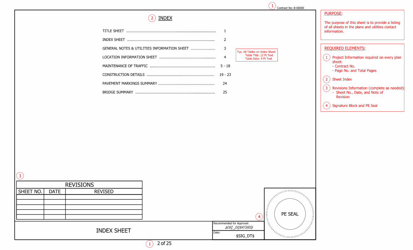
information.
of all sheets in the plans and utilities contact
The purpose of this sheet is to provide a listing
PURPOSE:
INDEX
INDEX SHEET
REVISIONS
SHEET NO. DATE REVISED
BRIDGE SUMMARY ........................................................................ 25
24PAVEMENT MARKINGS SUMMARY ...................................................
19 - 23CONSTRUCTION DETAILS .............................................................
5 - 18MAINTENANCE OF TRAFFIC ...........................................................
4LOCATION INFORMATION SHEET ...................................................
3GENERAL NOTES & UTILITIES INFORMATION SHEET ......................
2INDEX SHEET ...............................................................................
1TITLE SHEET .................................................................................
2
3
4
Signature Block and PE Seal 4
Revision
Sheet No., Date, and Note of-
Revisions Information (complete as needed): 3
Sheet Index 2
- Page No. and Total Pages
- Contract No.
sheet:
Project Information required on every plan 1
REQUIRED ELEMENTS:
Table Data: 9 Pt Text
Table Title: 12 Pt Text
Typ. All Tables on Index Sheet:
Date:
Recommended for Approval:
$SIG_DT$
$ENG_SIGNATURE$
Contract No:
of
1B-00000
1 3 25
PE SEAL
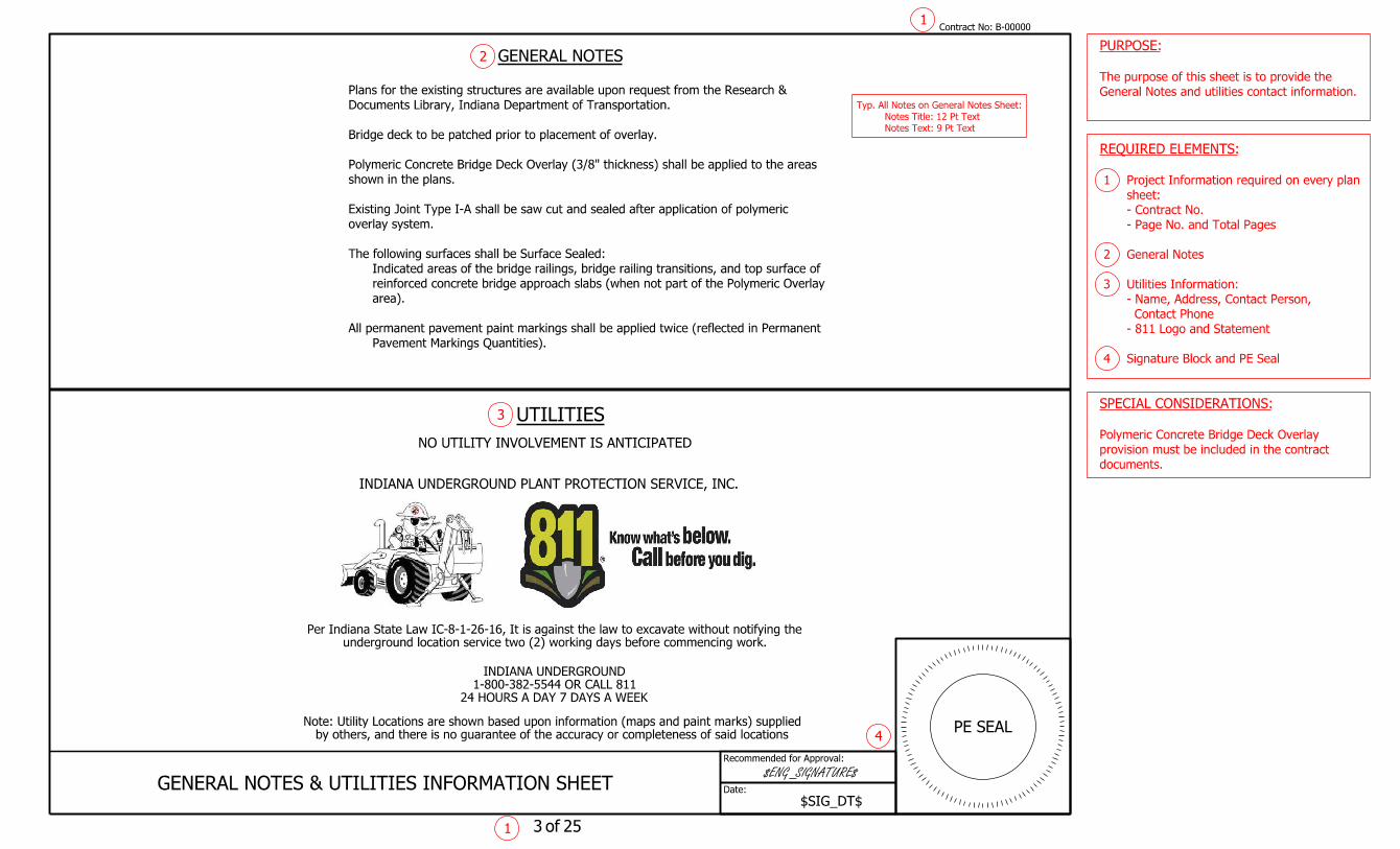
GENERAL NOTES & UTILITIES INFORMATION SHEET
INDIANA UNDERGROUND PLANT PROTECTION SERVICE, INC.
24 HOURS A DAY 7 DAYS A WEEK
1-800-382-5544 OR CALL 811
INDIANA UNDERGROUND
underground location service two (2) working days before commencing work.
Per Indiana State Law IC-8-1-26-16, It is against the law to excavate without notifying the
by others, and there is no guarantee of the accuracy or completeness of said locations
Note: Utility Locations are shown based upon information (maps and paint marks) supplied
NO UTILITY INVOLVEMENT IS ANTICIPATED
UTILITIES
documents.
provision must be included in the contract
Polymeric Concrete Bridge Deck Overlay
SPECIAL CONSIDERATIONS:
General Notes and utilities contact information.
The purpose of this sheet is to provide the
PURPOSE:
Pavement Markings Quantities).
All permanent pavement paint markings shall be applied twice (reflected in Permanent
area).
reinforced concrete bridge approach slabs (when not part of the Polymeric Overlay
Indicated areas of the bridge railings, bridge railing transitions, and top surface of
The following surfaces shall be Surface Sealed:
overlay system.
Existing Joint Type I-A shall be saw cut and sealed after application of polymeric
shown in the plans.
Polymeric Concrete Bridge Deck Overlay (3/8" thickness) shall be applied to the areas
Bridge deck to be patched prior to placement of overlay.
Documents Library, Indiana Department of Transportation.
Plans for the existing structures are available upon request from the Research &
GENERAL NOTES 2
3
4
Signature Block and PE Seal 4
- 811 Logo and Statement
Contact Phone
- Name, Address, Contact Person,
Utilities Information: 3
General Notes 2
- Page No. and Total Pages
- Contract No.
sheet:
Project Information required on every plan 1
REQUIRED ELEMENTS:
Notes Text: 9 Pt Text
Notes Title: 12 Pt Text
Typ. All Notes on General Notes Sheet:
Date:
Recommended for Approval:
$SIG_DT$
$ENG_SIGNATURE$
Contract No:
of
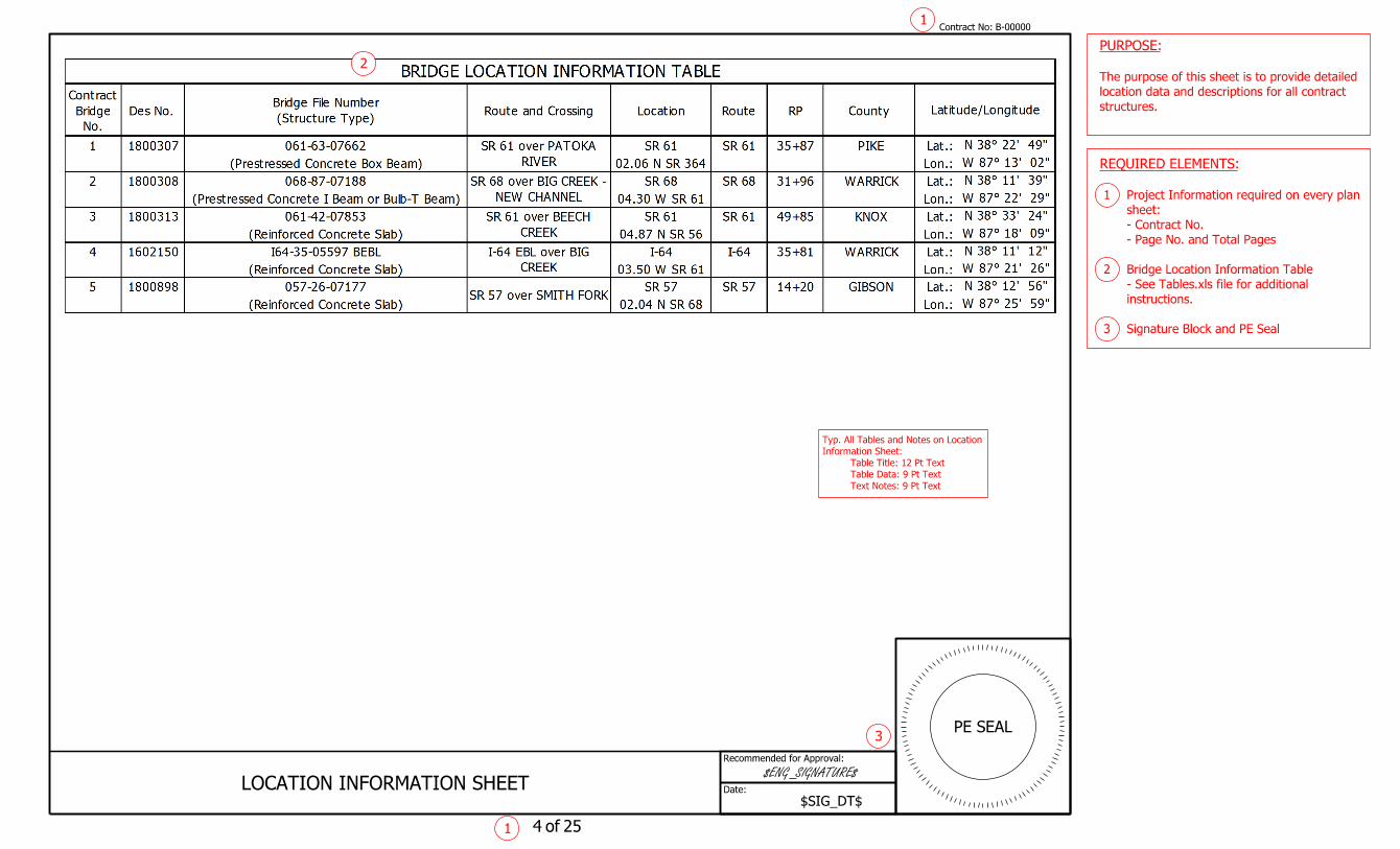
LOCATION INFORMATION SHEET
1B-00000
1 4 25
PE SEAL
structures.
location data and descriptions for all contract
The purpose of this sheet is to provide detailed
PURPOSE:
3
Signature Block and PE Seal 3
instructions.
- See Tables.xls file for additional
Bridge Location Information Table 2
- Page No. and Total Pages
- Contract No.
sheet:
Project Information required on every plan 1
REQUIRED ELEMENTS:
Text Notes: 9 Pt Text
Table Data: 9 Pt Text
Table Title: 12 Pt Text
Information Sheet:
Typ. All Tables and Notes on Location
2

Date:
Recommended for Approval:
$SIG_DT$
$ENG_SIGNATURE$
Contract No:
of
SUMMARY TABLE
MAINTENANCE OF TRAFFIC
1B-00000
1 5 25
PE SEAL
3
each contract structure.
summary of Maintenance of Traffic details for
The purpose of this sheet is to provide a
PURPOSE:
referenced for each location.
drawings or plan set sheet numbers
changed to "Proposed MOT" with standard
on the interstate. The "IHCP..." column ca be
This table can be amended for locations not
SPECIAL CONSIDERATIONS:
Not applicable to this project.**
NOTES
For Single Lane Closure Detail, see Sht. 7.
For Shoulder Closure Detail, see Sht. 6.
Any lane or shoulder closures outside the allowable times shown in the Traffic Summary require approval from the Engineer.
Nighttime Only: Single lane closure or single lane restriction in each direction any day of the week 9:00 p.m. to 6:00 a.m.
and weekdays 9:00 p.m. to 6:00 a.m.
Weekend or Nightime Only: Single lane closure or single lane restrictions in each direction between Friday 9:00 p.m. to Monday 6:00 a.m.
4
Signature Block and PE Seal 4
Notes 3
- See Tables.xls for additional instructions.
Maintenance of Traffic Summary: 2
- Page No. and Total Pages
- Contract No.
sheet:
Project Information required on every plan 1
REQUIRED ELEMENTS:
Text Notes: 9 Pt Text
Table Data: 9 Pt Text
Table Title: 12 Pt Text
Table Sheet:
Maintenance of Traffic Summary
Typ. All Tables and Notes on
2
Date:
Recommended for Approval:
$SIG_DT$
$ENG_SIGNATURE$
Contract No:
of
NOTES
SHOULDER CLOSURE DETAIL
MAINTENANCE OF TRAFFIC
1B-00000
1 6 25
PE SEAL
Summary table.
when included in the Maintenance of Traffic
and signage for a temporary shoulder closure
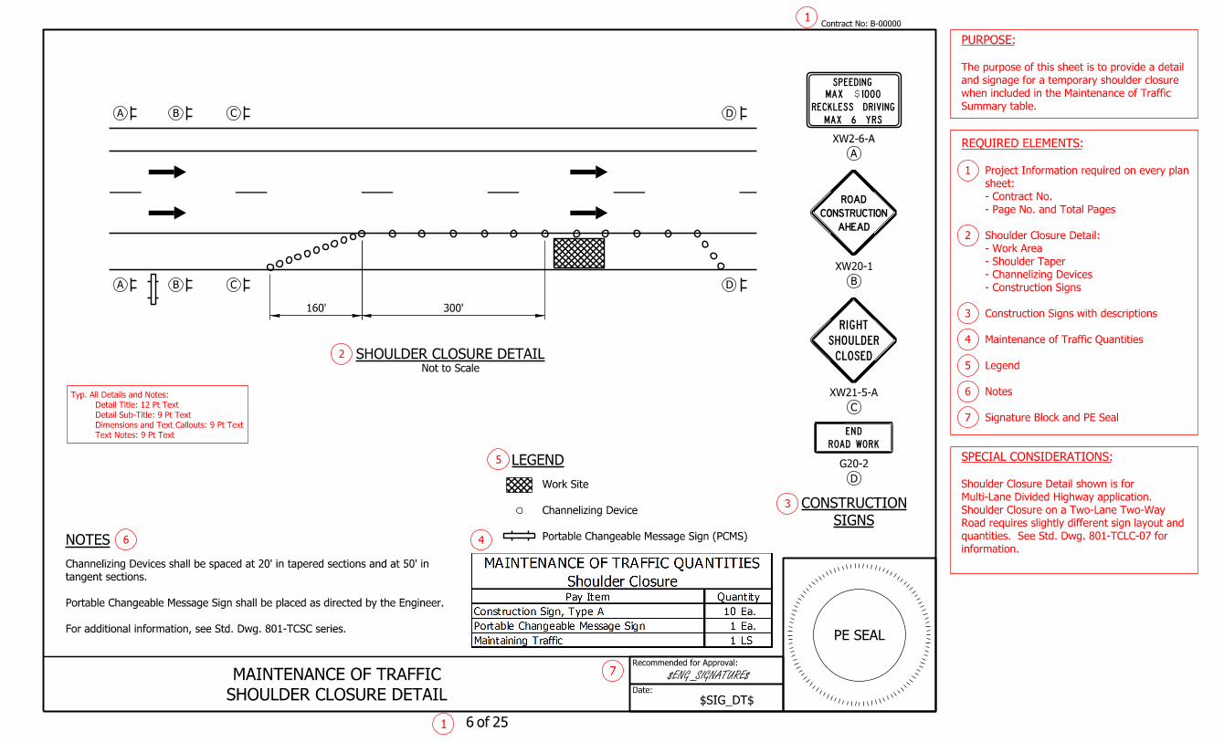
The purpose of this sheet is to provide a detail
PURPOSE:
information.
quantities. See Std. Dwg. 801-TCLC-07 for
Road requires slightly different sign layout and
Shoulder Closure on a Two-Lane Two-Way
Multi-Lane Divided Highway application.
Shoulder Closure Detail shown is for
SPECIAL CONSIDERATIONS:
For additional information, see Std. Dwg. 801-TCSC series.
Portable Changeable Message Sign shall be placed as directed by the Engineer.
tangent sections.
Channelizing Devices shall be spaced at 20' in tapered sections and at 50' in
LEGEND
Portable Changeable Message Sign (PCMS)
Channelizing Device
Work Site
B C D
160' 300'
B C DA
A
Not to Scale
SHOULDER CLOSURE DETAIL
B
C
D
SIGNS
CONSTRUCTION
XW20-1
XW21-5-A
G20-2
AHEAD
CONSTRUCTION
ROAD
DNE
R ROAD WO K
EDOS
R HTIG
L
OUSH L R
C
DE
SPEEDING
MAX 6 YRS
RECKLESS DRIVING
MAX 1000$
A
XW2-6-A
7
2
3
5
6 4
Signature Block and PE Seal 7
Notes 6
Legend 5
Maintenance of Traffic Quantities 4
Construction Signs with descriptions 3
- Construction Signs
- Channelizing Devices
- Shoulder Taper
- Work Area
Shoulder Closure Detail: 2
- Page No. and Total Pages
- Contract No.
sheet:
Project Information required on every plan 1
REQUIRED ELEMENTS:
Text Notes: 9 Pt Text
Dimensions and Text Callouts: 9 Pt Text
Detail Sub-Title: 9 Pt Text
Detail Title: 12 Pt Text
Typ. All Details and Notes:

Date:
Recommended for Approval:
$SIG_DT$
$ENG_SIGNATURE$
Contract No:
of
SINGLE LANE CLOSURE DETAIL
MAINTENANCE OF TRAFFIC
1B-00000
1 7 25
PE SEAL
Summary table.
when included in the Maintenance of Traffic
and signage for a temporary single-lane closure
The purpose of this sheet is to provide a detail
PURPOSE:
Flagger Detail.
Road requires a Temporary Signal and/or
Single Lane Closure on a Two-Lane Two-Way
Multi-Lane Divided Highway application.
Single Lane Closure Detail shown is for
detail.
included in the contract documents to use this
Truck Mounted Attentuator provision must be
SPECIAL CONSIDERATIONS:
LEGEND
NOTES
SIGNS
CONSTRUCTION
SPEEDING
MAX 6 YRS
RECKLESS DRIVING
MAX 1000$
Portable Changeable Message Sign (PCMS)
Channelizing Device
Flashing Arrow Sign
Truck Mounted Attenuator
Work Site
AHEAD
CONSTRUCTION
ROAD
EDSLO
ADEAH
C
HTGRI NEA L
A
XW2-6-A
XW20-1
B
C
XW20-5R (or L)
D
XW4-2R (or L)
E
G20-2
DNE
R ROAD WO K
B C D
B C D
E
L1000'1500'2640' Distance
Roll Ahead
L21Space
Buffer
100'
E
A
A
Not to Scale
SINGLE LANE CLOSURE DETAIL
(mph)
Prior to Construction Zone
Posted Speed Limit
Taper Length "L"
55
60
65
70
660'
720'
780'
840'
For additional information, see Std. Dwg. 801-TCLC series.
A Flashing Arrow Sign shall be used when a freeway lane is closed.
Roll-Ahead Distance shall be per Manufacturer's specifications.
not present.
Type III Barricade may replace Truck-Mounted Attenuators when workers are
Portable Changeable Message Sign shall be placed as directed by the Engineer.
tangent sections.
Channelizing Devices shall be spaced at 50' in tapered sections and at 100' in
8
2
3
7
4
6
5
Signature Block and PE Seal 8
Notes 7
Legend 6
Maintenance of Traffic Quantities 5
Table of Minimum Taper Lengths 4
Construction Signs with descriptions 3
- Construction Signs
- Flashing Arrow Sign
- Channelizing Devices
- Lane Taper
- Truck Mounted Attenuator
- Work Area
Single Lane Closure Detail: 2
- Page No. and Total Pages
- Contract No.
sheet:
Project Information required on every plan 1
REQUIRED ELEMENTS:
Text Notes: 9 Pt Text
Dimensions and Text Callouts: 9 Pt Text
Detail Sub-Title: 9 Pt Text
Detail Title: 12 Pt Text
Typ. All Details and Notes:
80'
100' 50'
100'
100'
70'
40'6' Zone
36' x 6' Detection
Zone
6' x 6' Detection
w/ Wireless Detection
Temp. Traffic Signal
Marking, Removable, 24"
12' Temp. Transverse Pavement
for Signs & Locations
See Advance Sign Layout
Type 2
380' Temp. Traffic Barrier
(Taper Rate ±7:1)
100' Temp. Traffic Barrier, Type 2
36 Lft Barricade, Type III-A 48 Lft Barricade, Type III-A
Type III-A
24 Lft Barricade,
Type III-A
36 Lft Barricade,
S.R. 61
PAT
OK
A RIV
ER P
AT
OK
A RIV
ER
MIL
L S
T.
UNIO
N S
T.
JEFFE
RSO
N S
T.
MAI
N S
T.
100'
140'
80'
6'
40'
Zone
36' x 6' Detection
Zone
6' x 6' Detection
Marking, Removable, 24"
12' Temp. Transverse Pvm't.
Type 2
380' Temp. Traffic Barrier
Type III-A
36 Lft Barricade,
Date:
Recommended for Approval:
MA
TC
HLIN
E A-A
MA
TC
HLIN
E A-A
Scale: 1" = 100'
DESIGN SPEED = 35 MPH
CONSTRUCTION ZONE
of1 8 25
PE SEAL
Contract No:1
B-00000
temporary signal.
maintenance of traffic plan employing a
descriptions, and quantities for one phase of
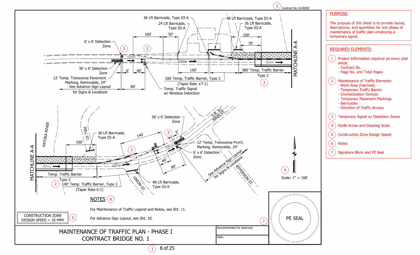
The purpose of this sheet is to provide layout,
PURPOSE:
For Advance Sign Layout, see Sht. 10.
For Maintenance of Traffic Legend and Notes, see Sht. 11.
NOTES
CONTRACT BRIDGE NO. 1
MAINTENANCE OF TRAFFIC PLAN - PHASE I
Type 2
Temp. Traffic Barrier
for Signs
& Locations
See
Advance Sign Layout
Type 2
Temp. Traffic Barrier
(Taper Rate 6:1)
140' Temp. Traffic Barrier, Type 2
3 2
2
2
6
2
3
4
75
Signature Block and PE Seal 7
Notes 6
Construction Zone Design Speed 5
North Arrow and Drawing Scale 4
Temporary Signal w/ Detection Zones 3
- Direction of Traffic Arrows
- Barricades
- Temporary Pavement Markings
- Channelization Devices
- Temporary Traffic Barrier
- Work Area (hatched)
Maintenance of Traffic Elements: 2
- Page No. and Total Pages
- Contract No.
sheet:
Project Information required on every plan 1
REQUIRED ELEMENTS:
Type III-A
48 Lft Barricade,

PAT
OK
A RIV
ER P
AT
OK
A RIV
ER
S.R. 61
80'
100'
40'6' Zone
36' x 6' Detection
Zone
6' x 6' Detection
Marking, Removable, 24"
12' Temp. Transverse Pavement
for Signs & Locations
See Advance Sign Layout
Type 2
400' Temp. Traffic Barrier
100'
(Taper Rate 10:1)
230' Temp. Traffic Barrier, Type 2
48 Lft Barricade, Type III-A
Type III-A
36 Lft Barricade,
S.R. 61
PAT
OK
A RIV
ER P
AT
OK
A RIV
ER
MIL
L S
T.
UNIO
N S
T.
JEFFE
RSO
N S
T.
MAI
N S
T.
100'
80'
6'
40'
Zone
36' x 6' Detection
Zone
6' x 6' Detection
Marking, Removable, 24"
12' Temp. Transverse Pvm't.
140'
Type 2
400' Temp. Traffic Barrier
Type III-A
36 Lft Barricade,
Date:
Recommended for Approval:
MA
TC
HLIN
E A-A
MA
TC
HLIN
E A-A
Scale: 1" = 100'
DESIGN SPEED = 35 MPH
CONSTRUCTION ZONE
of1 9 25
PE SEAL
Contract No:1
B-00000
temporary signal.
maintenance of traffic plan employing a
descriptions, and quantities for one phase of
The purpose of this sheet is to provide layout,
PURPOSE:
For Advance Sign Layout, see Sht. 10.
For Maintenance of Traffic Legend and Notes, see Sht. 11.
NOTES
CONTRACT BRIDGE NO. 1
MAINTENANCE OF TRAFFIC PLAN - PHASE II
Type 2
Temp. Traffic Barrier
for Signs
& Locations
See
Advance Sign Layout
(Taper Rate 6:1)
160' Temp. Traffic Barrier, Type 2
Type 2
Temp. Traffic Barrier
6
7
4
2
23
3
2
5
2Signature Block and PE Seal 7
Notes 6
Construction Zone Design Speed 5
North Arrow and Drawing Scale 4
Temporary Signal w/ Detection Zones 3
- Direction of Traffic Arrows
- Barricades
- Temporary Pavement Markings
- Channelization Devices
- Temporary Traffic Barrier
- Work Area (hatched)
Maintenance of Traffic Elements: 2
- Page No. and Total Pages
- Contract No.
sheet:
Project Information required on every plan 1
REQUIRED ELEMENTS:
Type III-A
48 Lft Barricade,

Date:
Recommended for Approval:
For Construction Sign Details, see Std. Dwg. 801-TCSN-12.
NOTES
LEGEND
Type "A" Low Intensity Light
Construction Sign
Not to Scale
(Typical Each Direction)
ADVANCE SIGN LAYOUT
500' 500' 1000' 500' 500' 500' 500'
"End Construction"
XG20-2
Speeding Penalty Sign
XW2-6a-B
Reckless Driving Penalty Sign
XW2-6b-B
"Road Construction Ahead"
XW20-1
"Watch for Stopped Traffic"
XW103-1
"One Lane Ahead" & "25 M.P.H."
XW20 & XW13-1-A
"Do Not Pass"
R4-1-A
"Signal Ahead"
XW3-3a-B
"Stop Here on Red"
R10-6
of1 10 25
PE SEAL
Contract No:1
B-00000
preceding sheets.
maintenance of traffic detailed on the
layout of advance signs required for the phased
The purpose of this sheet is to provide the
PURPOSE:
CONTRACT BRIDGE NO. 1
ADVANCE SIGN LAYOUT
on MOT Plan
Stop Bar as shown
4
5
3
2
Signature Block and PE Seal 5
Notes 4
Legend 3
Advance Sign Layout 2
- Page No. and Total Pages
- Contract No.
sheet:
Project Information required on every plan 1
REQUIRED ELEMENTS:
Date:
Recommended for Approval:
LEGEND
Barricade, Type III-A
Temporary Traffic Signal & Support
Temporary Traffic Barrier
Work Area
Direction of Traffic
Channelizing Device
Flashing Arrow Sign
Construction Warning Light, Type A
Construction Sign
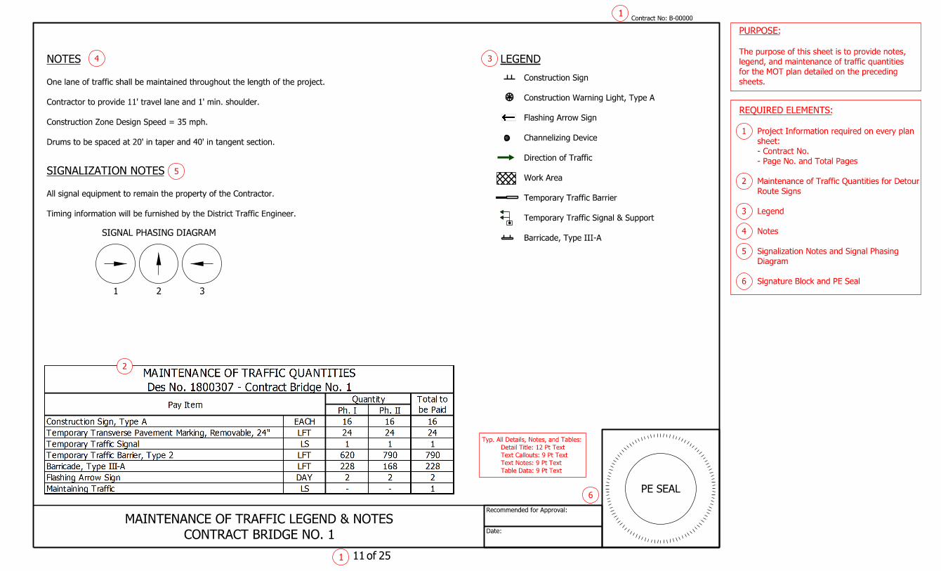
Timing information will be furnished by the District Traffic Engineer.
All signal equipment to remain the property of the Contractor.
SIGNALIZATION NOTES
Drums to be spaced at 20' in taper and 40' in tangent section.
Construction Zone Design Speed = 35 mph.
Contractor to provide 11' travel lane and 1' min. shoulder.
One lane of traffic shall be maintained throughout the length of the project.
NOTES
of1 11 25
PE SEAL
Contract No:1
B-00000
sheets.
for the MOT plan detailed on the preceding
legend, and maintenance of traffic quantities
The purpose of this sheet is to provide notes,
PURPOSE:
CONTRACT BRIDGE NO. 1
MAINTENANCE OF TRAFFIC LEGEND & NOTES
1 2 3
SIGNAL PHASING DIAGRAM
4
5
3
6
2
Signature Block and PE Seal 6
Diagram
Signalization Notes and Signal Phasing 5
Notes 4
Legend 3
Route Signs
Maintenance of Traffic Quantities for Detour 2
- Page No. and Total Pages
- Contract No.
sheet:
Project Information required on every plan 1
REQUIRED ELEMENTS:
Table Data: 9 Pt Text
Text Notes: 9 Pt Text
Text Callouts: 9 Pt Text
Detail Title: 12 Pt Text
Typ. All Details, Notes, and Tables:
Date:
Recommended for Approval:
NOTES
1
21
C
C
2
Detail.
See I-69/SR 68
4
C
C
C
C
2 1
2
2
A
A
A
B
B
B
EC
C
D
D
C
C
A
B
B
BA
A
4
C
F
C
C
D
6
Not to Scale
I-69/I-64 DETAILNot to Scale
I-69/SR 68 DETAIL
Not to Scale
I-64/SR 61/SR 68 DETAIL
0 1 mi
D
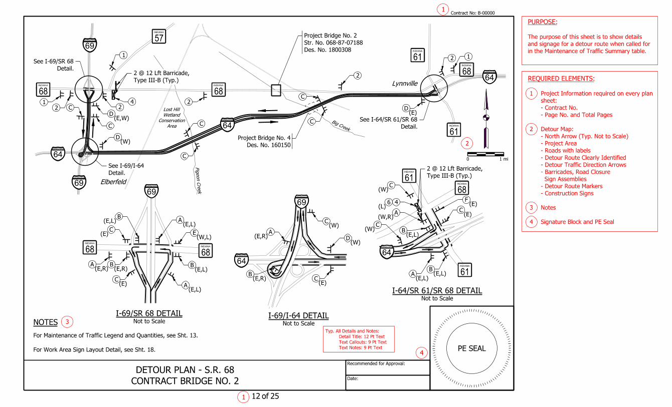
For Work Area Sign Layout Detail, see Sht. 18.
For Maintenance of Traffic Legend and Quantities, see Sht. 13.
Elberfeld
Area
Conservation
Wetland
Lost Hill
Lynnville
Type III-B (Typ.)
2 @ 12 Lft Barricade,
Detail.
See I-64/SR 61/SR 68
1
1
of12 25
Contract No:B-00000
PE SEAL
in the Maintenance of Traffic Summary table.
and signage for a detour route when called for
The purpose of this sheet is to show details
PURPOSE:
CONTRACT BRIDGE NO. 2
DETOUR PLAN - S.R. 68
Des. No. 1800308
Str. No. 068-87-07188
Project Bridge No. 2
Des. No. 160150
Project Bridge No. 4
68INDIANA
57INDIANA
61INDIANA
68INDIANA
61INDIANA
68INDIANA
61INDIANA
61INDIANA
68INDIANA
68INDIANA
68INDIANA
Big Creek
Pigeon Cre
ek
Detail.
See I-69/I-64
Type III-B (Typ.)
2 @ 12 Lft Barricade,
2
3
4
Signature Block and PE Seal 4
Notes 3
- Construction Signs
- Detour Route Markers
Sign Assemblies
- Barricades, Road Closure
- Detour Traffic Direction Arrows
- Detour Route Clearly Identified
- Roads with labels
- Project Area
- North Arrow (Typ. Not to Scale)
Detour Map: 2
- Page No. and Total Pages
- Contract No.
sheet:
Project Information required on every plan 1
REQUIRED ELEMENTS:
INTERSTATE
69
INTERSTATE
64
INTERSTATE
69
INTERSTATE
64
INTERSTATE
64
INTERSTATE
64INTERSTATE
64
INTERSTATE
69INTERSTATE
69
(E,W)
(E,L)
(E,L)
(W,L)
(E,L)(E,L)
(E,R) (E,R)
(E)
(E)(E,R)
(E,R)
(W)
(W)
(E)(E,L)
(E,L)
(E,L)
(W,R)
(E)
(E)
(E)
(W)
(L)
(W)
(W)
Text Notes: 9 Pt Text
Text Callouts: 9 Pt Text
Detail Title: 12 Pt Text
Typ. All Details and Notes:
Date:
Recommended for Approval:
DETOUR ROUTE MARKERS
NOTES
INDIANA
68
EAST
DETOUR XM 4-8
(East or West)
M3-2S or M3-4S
M1-5
M5-1(L or R)S
A
INDIANA
68
EAST
DETOUR XM 4-8
(East or West)
M3-2S or M3-4S
M1-5
M6-1(L or R)S
B
INDIANA
68
EAST
DETOUR XM 4-8
(East or West)
M3-2S or M3-4S
M1-5
M6-3S
C
INDIANA
68
EAST
DETOUR
XM 4-8
(East or West)
M3-2S or M3-4S
M1-5
M6-2(R)S
D
INDIANA
68
DETOUR
ENDXM 4-8a
M1-5
M6-1(L or R)S
E
INDIANA
68
DETOUR
ENDXM 4-8a
M1-5
M6-3S
F
LEGEND
E
W
L
R Right
Left
West
East
Type "A" Low Intensity Light
Road Closure Sign Assembly
Type III Barricade &
Type III Barricade
Construction Sign
1
1
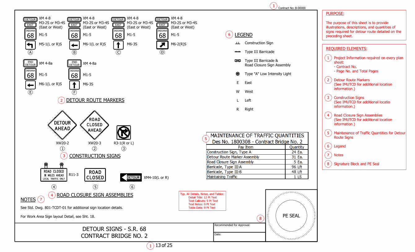
preceding sheet.
signs required for detour route detailed on the
illustrations, descriptions, and quantities of
The purpose of this sheet is to provide
PURPOSE:
For Work Area Sign layout Detail, see Sht. 18.
See Std. Dwg. 801-TCDT-01 for additional sign location details.
of13 25
Contract No:B-00000
PE SEAL
ROAD CLOSURE SIGN ASSEMBLIES
CONSTRUCTION SIGNS
R3-1(R or L)
3
XW20-2 XW20-3
1 2
5 6
XM4-10(L or R)R11-3
4
E
A
O
A
D
H DE
S
AR D
OLC
S
A
OL DE
OR
C
D
U
HA E DA
RED TO
OURDETXX
OL S DECOR A D
RT FAAC L NO YLIF C
LI SEM DA
OL
A EH
CONTRACT BRIDGE NO. 2
DETOUR SIGNS - S.R. 68
6
8
5
Signature Block and PE Seal 8
Notes 7
Legend 6
Route Signs
Maintenance of Traffic Quantities for Detour 5
information.)
(See IMUTCD for additional location
Road Closure Sign Assemblies 4
information.)
(See IMUTCD for additional locatio
Construction Signs 3
information.)
(See IMUTCD for additional location
Detour Route Markers 2
- Page No. and Total Pages
- Contract No.
sheet:
Project Information required on every plan 1
REQUIRED ELEMENTS:
Table Data: 9 Pt Text
Text Notes: 9 Pt Text
Text Callouts: 9 Pt Text
Detail Title: 12 Pt Text
Typ. All Details, Notes, and Tables:
2
4
7
3
Date:
Recommended for Approval:
NOTES
0 2 mi
150
50
50
B
B
B
A
A
A
A
2
2
2
21
1
C
C
C
C
C
E
D
4
46
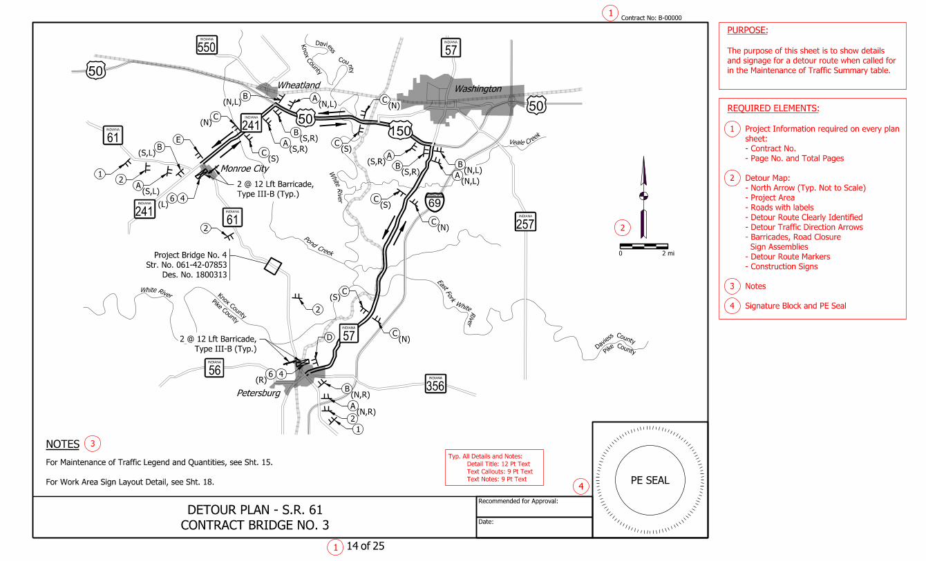
For Work Area Sign Layout Detail, see Sht. 18.
For Maintenance of Traffic Legend and Quantities, see Sht. 15.
1
1
in the Maintenance of Traffic Summary table.
and signage for a detour route when called for
The purpose of this sheet is to show details
PURPOSE:
of14 25
Contract No:B-00000
PE SEAL
CONTRACT BRIDGE NO. 3
DETOUR PLAN - S.R. 61
241INDIANA
57INDIANA
56INDIANA
61INDIANA
61INDIANA
57INDIANA
257INDIANA
356INDIANA
241INDIANA
550INDIANA
B
6
East
Fork
WhiteRiver
WhiteRiver
White
River
Creek
Pond
Cree
kVeale
Wheatland Washington
Petersburg
Monroe City
Daviess
County
Pike
County
Pike County
Knox County
Knox
Cou
nty
Daviess
County
Type III-B (Typ.)
2 @ 12 Lft Barricade,
Type III-B (Typ.)
2 @ 12 Lft Barricade,
3
4
2
Des. No. 1800313
Str. No. 061-42-07853
Project Bridge No. 4
Signature Block and PE Seal 4
Notes 3
- Construction Signs
- Detour Route Markers
Sign Assemblies
- Barricades, Road Closure
- Detour Traffic Direction Arrows
- Detour Route Clearly Identified
- Roads with labels
- Project Area
- North Arrow (Typ. Not to Scale)
Detour Map: 2
- Page No. and Total Pages
- Contract No.
sheet:
Project Information required on every plan 1
REQUIRED ELEMENTS:
INTERSTATE
69
50
(N,R)
(N,R)
(R)
(N,L)
(S,R)
(S,R)
(S,R)
(S,R)(S,L)
(S,L)
(L)
(N)
(N)
(N)
(S)
(S)
(S)
(N,L)
(N)
(S)
(N,L)(N,L)
Text Notes: 9 Pt Text
Text Callouts: 9 Pt Text
Detail Title: 12 Pt Text
Typ. All Details and Notes:
B A
B
A
C
C
C

Date:
Recommended for Approval:
DETOUR ROUTE MARKERS
NOTES
INDIANA
61
DETOUR
ENDXM 4-8a
M1-5
M6-1(L or R)S
D
LEGEND
N
S
L
R
INDIANA
61
NORTH
DETOUR XM 4-8
(North or South)
M3-1S or M3-3S
M1-5
M5-1(L or R)S
A
INDIANA
61
NORTH
DETOUR XM 4-8
(North or South)
M3-1S or M3-3S
M1-5
M6-1(L or R)S
B
INDIANA
61
NORTH
DETOUR XM 4-8
(North or South)
M3-1S or M3-3S
M1-5
M6-3S
C
Right
Left
South
North
Type "A" Low Intensity Light
Road Closure Sign Assembly
Type III Barricade &
Type III Barricade
Construction Sign
INDIANA
61
DETOUR
ENDXM 4-8a
M1-5
M6-3S
E
1
preceding sheet.
signs required for detour route detailed on the
illustrations, descriptions, and quantities of
The purpose of this sheet is to provide
PURPOSE:
1
For Work Area Sign layout Detail, see Sht. 18.
See Std. Dwg. 801-TCDT-01 for additional sign location details.
of15 25
Contract No:B-00000
PE SEAL
CONSTRUCTION SIGNS
R3-1(R or L)
3
XW20-2 XW20-3
1 2
5 6
XM4-10(L or R)R11-3
4
E
A
O
A
D
H DE
S
AR D
OLC
S
A
OL DE
OR
C
D
U
HA E DA
RED TO
OURDETXX
OL S DECOR A D
RT FAAC L NO YLIF C
LI SEM DA
OL
A EH
ROAD CLOSURE SIGN ASSEMBLIES
CONTRACT BRIDGE NO. 3
DETOUR SIGNS - S.R. 61
6
8
5
Signature Block and PE Seal 8
Notes 7
Legend 6
Route Signs
Maintenance of Traffic Quantities for Detour 5
information.)
(See IMUTCD for additional location
Road Closure Sign Assemblies 4
information.)
(See IMUTCD for additional locatio
Construction Signs 3
information.)
(See IMUTCD for additional location
Detour Route Markers 2
- Page No. and Total Pages
- Contract No.
sheet:
Project Information required on every plan 1
REQUIRED ELEMENTS:
Table Data: 9 Pt Text
Text Notes: 9 Pt Text
Text Callouts: 9 Pt Text
Detail Title: 12 Pt Text
Typ. All Details, Notes, and Tables:
2
3
4
7

Date:
Recommended for Approval:
NOTES
Not to Scale
I-69/SR 68 DETAIL
CR 700 S
Detail.
See I-69/SR 168
4
4
Not to Scale
I-69/SR 168 DETAIL
OLD S
R 5
7
Detail.
See I-69/SR 68
B
B
A
A
C
C
B
B
A
A
C
C
C
C
CC
D
D
B
A2
1
2
2
F
C
E
6
0 1 mi
For Work Area Sign Layout Detail, see Sht. 18.
For Maintenance of Traffic Legend and Quantities, see Sht. 17.
Mackey
1
1
in the Maintenance of Traffic Summary table.
and signage for a detour route when included
The purpose of this sheet is to show details
PURPOSE:
of16 25
Contract No:B-00000
PE SEAL
Des. No. 1800308
Project Bridge No. 2
CONTRACT BRIDGE NO. 5
DETOUR PLAN - S.R. 57
168INDIANA
68INDIANA
68INDIANA
57INDIANA
168INDIANA
168INDIANA
68INDIANA
68INDIANA
Smith Fork
Big Creek
Creek
Pigeon
Buckskin
Type III-B (Typ.)
2 @ 12 Lft Barricade,
Type III-B (Typ.)
2 @ 12 Lft Barricade,
3
4
2
Des. No. 1800898
Str. No. 057-26-07177
Project Bridge No. 5
Signature Block and PE Seal 4
Notes 3
- Construction Signs
- Detour Route Markers
Sign Assemblies
- Barricades, Road Closure
- Detour Traffic Direction Arrows
- Detour Route Clearly Identified
- Roads with labels
- Project Area
- North Arrow (Typ. Not to Scale)
Detour Map: 2
- Page No. and Total Pages
- Contract No.
sheet:
Project Information required on every plan 1
REQUIRED ELEMENTS:
INTERSTATE
64INTERSTATE
69
INTERSTATE
69
INTERSTATE
69
INTERSTATE
69
(S)
(N)
(N)
(S)
(N)
(N)
(N)
(N)
(L)
(S)
(S)
(S)
(L)
(N,R)
(N,R)
(N,R)
(N,R)
(S,L)
(S,L)
(S,L) (S,L)
(S,R)
(S,R)
Text Notes: 9 Pt Text
Text Callouts: 9 Pt Text
Detail Title: 12 Pt Text
Typ. All Details and Notes:

Date:
Recommended for Approval:
DETOUR ROUTE MARKERS
NOTES
INDIANA
57
DETOUR
ENDXM 4-8a
M1-5
M6-1(L or R)S
E
LEGEND
N
S
L
R
INDIANA
57
NORTH
DETOUR XM 4-8
(North or South)
M3-1S or M3-3S
M1-5
M5-1(L or R)S
A
INDIANA
57
NORTH
DETOUR XM 4-8
(North or South)
M3-1S or M3-3S
M1-5
M6-1(L or R)S
B
INDIANA
57
NORTH
DETOUR XM 4-8
(North or South)
M3-1S or M3-3S
M1-5
M6-3S
C
INDIANA
57
NORTH
DETOUR
XM 4-8
(North or South)
M3-1S or M3-3S
M1-5
M6-2(R)S
D
INDIANA
57
DETOUR
ENDXM 4-8a
M1-5
F
Right
Left
South
North
Type "A" Low Intensity Light
Road Closure Sign Assembly
Type III Barricade &
Type III Barricade
Construction Sign
1
preceding sheet.
signs required for detour route detailed on the
illustrations, descriptions, and quantities of
The purpose of this sheet is to provide
PURPOSE:
1
For Work Area Sign Layout Detail, see Sht. 18.
See Std. Dwg. 801-TCDT-01 for additional sign location details.
of17 25
B-00000
PE SEAL
CONSTRUCTION SIGNS
R3-1(R or L)
3
XW20-2 XW20-3
1 2
5 6
XM4-10(L or R)R11-3
4
E
A
O
A
D
H DE
S
AR D
OLC
S
A
OL DE
OR
C
D
U
HA E DA
RED TO
OURDETXX
OL S DECOR A D
RT FAAC L NO YLIF C
LI SEM DA
OL
A EH
ROAD CLOSURE SIGN ASSEMBLIES
CONTRACT BRIDGE NO. 5
DETOUR SIGNS - S.R. 57
Contract No:
6
8
5
Signature Block and PE Seal 8
Notes 7
Legend 6
Route Signs
Maintenance of Traffic Quantities for Detour 5
information.)
(See IMUTCD for additional location
Road Closure Sign Assemblies 4
information.)
(See IMUTCD for additional locatio
Construction Signs 3
information.)
(See IMUTCD for additional location
Detour Route Markers 2
- Page No. and Total Pages
- Contract No.
sheet:
Project Information required on every plan 1
REQUIRED ELEMENTS:
Table Data: 9 Pt Text
Text Notes: 9 Pt Text
Text Callouts: 9 Pt Text
Detail Title: 12 Pt Text
Typ. All Details, Notes, and Tables:
2
3
4
7

Date:
Recommended for Approval:
NOTES
LEGEND
WORK AREA SIGN LAYOUT DETAIL
MAINTENANCE OF TRAFFIC
Work Area
Type "A" Low Intensity Light
Road Closure Sign Assembly
Type III Barricade &
Type III Barricade
Construction Sign
For additional information, see Std. Dwg. 801-TCSC-01 through -03.
Worksite Added Penalty Signs to be placed as stated in RSP 801-R-542.
Work Area
2 3 4
234
Not to Scale
WORK AREA SIGN LAYOUT DETAIL
500'500'1000'
500' 500' 1000'
Barricade Placement.)
(See Std. Dwg. 801-TCDV-07 for
(Typ. Ea. End)
Barricade & Road Closure Sign Assembly
2 @ 24 Lft (48 Lft Total) Type III-A
1
plans.
rural detours detailed on other sheets in the
and signage for the work area to accompany
The purpose of this sheet is to provide a detail
PURPOSE:
1 of18 25
Contract No:B-00000
PE SEAL
CONSTRUCTION SIGNS
R11-2
XW20-3
2
5
XW20-3
3
XW20-3
4
SIGN ASSEMBLIES
ROAD CLOSURE
E
A
O
A
D
H DE
S
AR D
OLC
CLOSED
ROAD
1000FT
500 FT
CLOSED
ROAD
S
A
OL DE
OR
C
D
5
3
8
4
5
Signature Block and PE Seal 8
Notes 7
Legend 6
Quantities for each Location)
Area Signs (to be included in MOT
Maintenance of Traffic Quantities for Work 5
information.)
(See IMUTCD for additional location
Road Closure Sign Assemblies 4
information.)
(See IMUTCD for additional location
Construction Signs 3
Work Area Sign Layout Detail 2
- Page No. and Total Pages
- Contract No.
sheet:
Project Information required on every plan 1
REQUIRED ELEMENTS:
Text Notes: 9 Pt Text
Text Callouts: 9 Pt Text
Detail Title: 12 Pt Text
Typ. All Details and Notes:
2
7
6
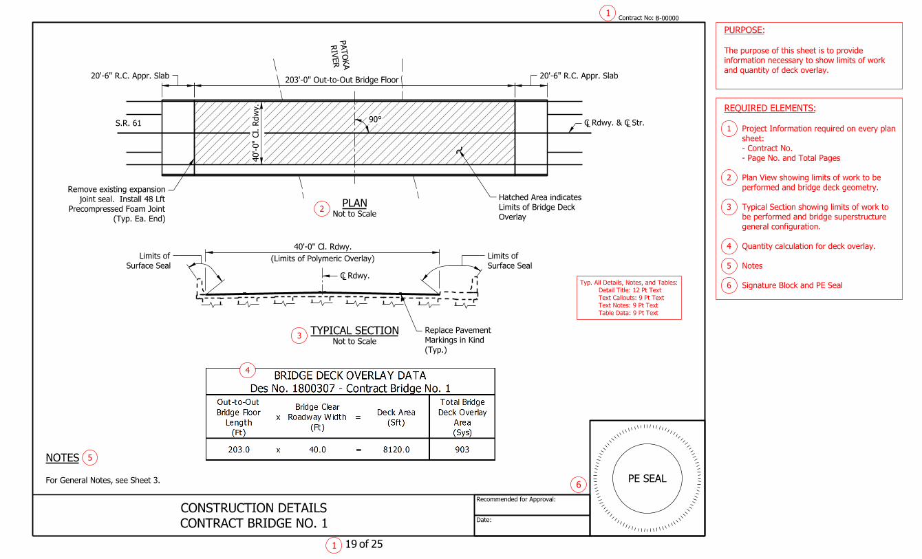
Overlay
Limits of Bridge Deck
Hatched Area indicates
Date:
Recommended for Approval:
Contract No:
of
For General Notes, see Sheet 3.
NOTES
1
1
203'-0" Out-to-Out Bridge Floor
Not to Scale
TYPICAL SECTION
(Limits of Polymeric Overlay)
40'-0" Cl. Rdwy.
LC Rdwy.
S.R. 61
RIV
ER
PAT
OK
A
(Typ.)
Markings in Kind
Replace Pavement
90°
Not to Scale
PLAN
and quantity of deck overlay.
information necessary to show limits of work
The purpose of this sheet is to provide
PURPOSE:
19 25
B-00000
PE SEAL
Surface Seal
Limits of
Surface Seal
Limits of
CONTRACT BRIDGE NO. 1
CONSTRUCTION DETAILS
3
6
40'-0"
Cl. R
dw
y.
20'-6" R.C. Appr. Slab20'-6" R.C. Appr. Slab
LLC Rdwy. & C Str.
4
Signature Block and PE Seal 6
Notes 5
Quantity calculation for deck overlay. 4
general configuration.
be performed and bridge superstructure
Typical Section showing limits of work to 3
performed and bridge deck geometry.
Plan View showing limits of work to be 2
- Page No. and Total Pages
- Contract No.
sheet:
Project Information required on every plan 1
REQUIRED ELEMENTS:
Table Data: 9 Pt Text
Text Notes: 9 Pt Text
Text Callouts: 9 Pt Text
Detail Title: 12 Pt Text
Typ. All Details, Notes, and Tables:
(Typ. Ea. End)
Precompressed Foam Joint
joint seal. Install 48 Lft
Remove existing expansion
5
2

Overlay
Limits of Bridge Deck
Hatched Area indicates
Date:
Recommended for Approval:
Contract No:
of
For General Notes, see Sheet 3.
NOTES
1
1
202'-0" Out-to-Out Bridge Floor
Not to Scale
TYPICAL SECTION
(Limits of Polymeric Overlay)
45'-4" Cl. Rdwy.
LC Rdwy.
S.R. 68
(Typ.)
Markings in Kind
Replace Pavement
Not to Scale
PLAN
and quantity of deck overlay.
information necessary to show limits of work
The purpose of this sheet is to provide
PURPOSE:
20 25
BIG C
REEK
B-00000
PE SEAL
Surface Seal
Limits of
Surface Seal
Limits of
50' App. Ex. R/W
50' App. Ex. R/W
Riprap in area of erosion damage.
Place 3.5 Cys of 18" Revetment
the existing pavement.
contains work requiring Contractor to be off of
Show Existing R/W only when contract
SPECIAL CONSIDERATIONS:
CONTRACT BRIDGE NO. 2
CONSTRUCTION DETAILS
Skew: 55° Lt.
3
6
45'-4"
Cl. R
dw
y.
LLC Rdwy. & C Str.
20'-6" Min. R.C. Appr. Slab20'-6" Min. R.C. Appr. Slab
4
Signature Block and PE Seal 6
Notes 5
Quantity calculation for deck overlay. 4
general configuration.
be performed and bridge superstructure
Typical Section showing limits of work to 3
performed and bridge deck geometry.
Plan View showing limits of work to be 2
- Page No. and Total Pages
- Contract No.
sheet:
Project Information required on every plan 1
REQUIRED ELEMENTS:
Table Data: 9 Pt Text
Text Notes: 9 Pt Text
Text Callouts: 9 Pt Text
Detail Title: 12 Pt Text
Typ. All Details, Notes, and Tables:
5
2
Overlay
Limits of Bridge Deck
Hatched Area indicates
Date:
Recommended for Approval:
Contract No:
of
For General Notes, see Sheet 3.
NOTES
1
1
Not to Scale
TYPICAL SECTION
(Limits of Polymeric Overlay)
36'-8" Cl. Rdwy.
LC Rdwy.
S.R. 57
(Typ.)
Markings in Kind
Replace Pavement
Not to Scale
PLAN
and quantity of deck overlay.
information necessary to show limits of work
The purpose of this sheet is to provide
PURPOSE:
21 25
CREE
KBEEC
H
B-00000
PE SEAL
Surface Seal
Limits of
Surface Seal
Limits of
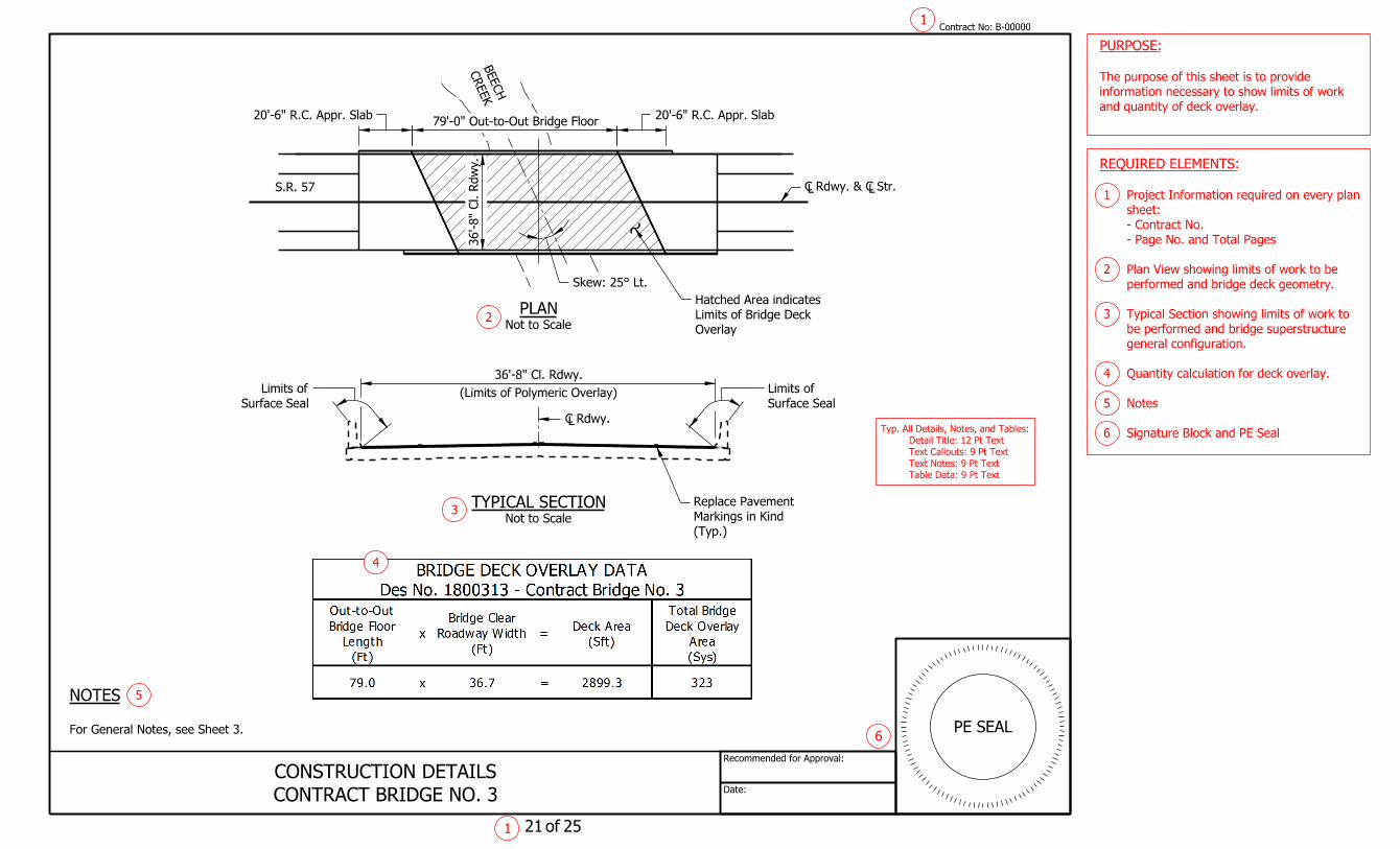
CONTRACT BRIDGE NO. 3
CONSTRUCTION DETAILS
Skew: 25° Lt.
3
6
79'-0" Out-to-Out Bridge Floor
36'-8"
Cl. R
dw
y.
20'-6" R.C. Appr. Slab20'-6" R.C. Appr. Slab
LLC Rdwy. & C Str.
4
Signature Block and PE Seal 6
Notes 5
Quantity calculation for deck overlay. 4
general configuration.
be performed and bridge superstructure
Typical Section showing limits of work to 3
performed and bridge deck geometry.
Plan View showing limits of work to be 2
- Page No. and Total Pages
- Contract No.
sheet:
Project Information required on every plan 1
REQUIRED ELEMENTS:
Table Data: 9 Pt Text
Text Notes: 9 Pt Text
Text Callouts: 9 Pt Text
Detail Title: 12 Pt Text
Typ. All Details, Notes, and Tables:
5
2

Overlay
Limits of Bridge Deck
Hatched Area indicates
Date:
Recommended for Approval:
Contract No:
of
For General Notes, see Sheet 3.
NOTES
1
1
Not to Scale
TYPICAL SECTION
(Limits of Polymeric Overlay)
39'-4" Cl. Rdwy.
LC Rdwy.
(Typ.)
Markings in Kind
Replace Pavement
Not to Scale
PLAN
and quantity of deck overlay.
information necessary to show limits of work
The purpose of this sheet is to provide
PURPOSE:
22 25
BIG C
REE
K
I-64 (EBL)
B-00000
PE SEAL
Surface Seal
Limits of
Surface Seal
Limits of
CONTRACT BRIDGE NO. 4
CONSTRUCTION DETAILS
Skew: 10° Lt.
3
6
119'-0" Out-to-Out Bridge Floor
39'-4"
Cl. R
dw
y.
LLC Rdwy. & C Str.
20'-6" Min. R.C. Appr. Slab20'-6" Min. R.C. Appr. Slab
4
Signature Block and PE Seal 6
Notes 5
Quantity calculation for deck overlay. 4
general configuration.
be performed and bridge superstructure
Typical Section showing limits of work to 3
performed and bridge deck geometry.
Plan View showing limits of work to be 2
- Page No. and Total Pages
- Contract No.
sheet:
Project Information required on every plan 1
REQUIRED ELEMENTS:
Table Data: 9 Pt Text
Text Notes: 9 Pt Text
Text Callouts: 9 Pt Text
Detail Title: 12 Pt Text
Typ. All Details, Notes, and Tables:
5
2

Overlay
Limits of Bridge Deck
Hatched Area indicates
Date:
Recommended for Approval:
Contract No:
of
For General Notes, see Sheet 3.
NOTES
1
1
Not to Scale
TYPICAL SECTION
(Limits of Polymeric Overlay)
45'-4" Cl. Rdwy.
LC Rdwy.
S.R. 57
(Typ.)
Markings in Kind
Replace Pavement
Not to Scale
PLAN
and quantity of deck overlay.
information necessary to show limits of work
The purpose of this sheet is to provide
PURPOSE:
23 25
FO
RK
SMIT
H
B-00000
PE SEAL
Surface Seal
Limits of
Surface Seal
Limits of
CONTRACT BRIDGE NO. 5
CONSTRUCTION DETAILS
Skew: 40° Rt.
3
4
6
116'-0" Out-to-Out Bridge Floor
45'-4"
Cl. R
dw
y.
LLC Rdwy. & C Str.
20'-6" Min. R.C. Appr. Slab20'-6" Min. R.C. Appr. Slab
Signature Block and PE Seal 6
Notes 5
Quantity calculation for deck overlay. 4
general configuration.
be performed and bridge superstructure
Typical Section showing limits of work to 3
performed and bridge deck geometry.
Plan View showing limits of work to be 2
- Page No. and Total Pages
- Contract No.
sheet:
Project Information required on every plan 1
REQUIRED ELEMENTS:
Table Data: 9 Pt Text
Text Notes: 9 Pt Text
Text Callouts: 9 Pt Text
Detail Title: 12 Pt Text
Typ. All Details, Notes, and Tables:
5
2
Date:
Recommended for Approval:
$SIG_DT$
$ENG_SIGNATURE$
Contract No:
of
1
1 24 25
B-00000
PE SEAL4
3
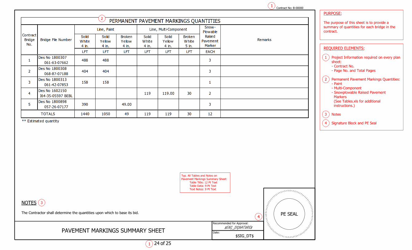
contract.
summary of quantities for each bridge in the
The purpose of this sheet is to provide a
PURPOSE:
PAVEMENT MARKINGS SUMMARY SHEET
The Contractor shall determine the quantities upon which to base its bid.
NOTES
Signature Block and PE Seal 4
Notes 3
instructions.)
(See Tables.xls for additional
Markers
- Snowplowable Raised Pavement
- Multi-Component
- Paint
Permanent Pavement Markings Quantities: 2
- Page No. and Total Pages
- Contract No.
sheet:
Project Information required on every plan 1
REQUIRED ELEMENTS:
2
Text Notes: 9 Pt Text
Table Data: 9 Pt Text
Table Title: 12 Pt Text
Pavement Markings Summary Sheet:
Typ. All Tables and Notes on

Date:
Recommended for Approval:
$SIG_DT$
$ENG_SIGNATURE$
Contract No:
of
1
1 25 25
B-00000
PE SEAL4
3
contract.
summary of quantities for each bridge in the
The purpose of this sheet is to provide a
PURPOSE:
BRIDGE SUMMARY SHEET
The Contractor shall determine the quantities upon which to base its bid.
NOTES
Signature Block and PE Seal 4
Notes 3
instructions.)
(See Tables.xls for additional
Quantities
- Bridge Deck Overlay and related
Summary of Bridge Quantities: 2
- Page No. and Total Pages
- Contract No.
sheet:
Project Information required on every plan 1
REQUIRED ELEMENTS:
2
Text Notes: 9 Pt Text
Table Data: 9 Pt Text
Table Title: 12 Pt Text
Summary Sheet:
Typ. All Tables and Notes on Bridge