Embed Size (px)
Citation preview
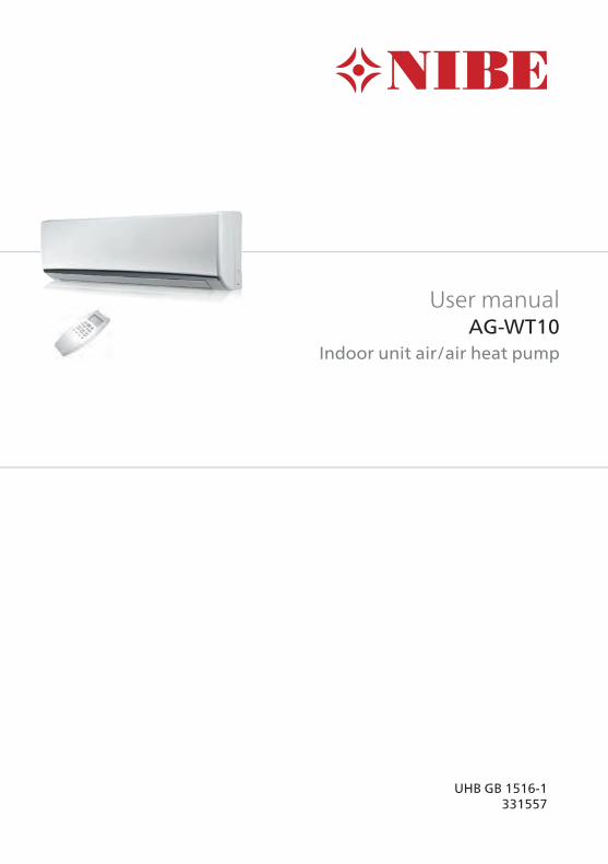
User manualAG-WT10
Indoor unit air/air heat pump
UHB GB 1516-1331557

Table of Contents31 Important information3Installation data
4Safety information
5Serial number
6AG-WT10 – an excellent choice
7Safety instructions
8Recovery
102 Design123 Remote control12Before use
14Overview
16Function without remote control
174 Function modes17Cooling
18Heating
19Automatic mode heat/cooling
21Dehumidification
22Ventilation
22Function in the event of power cut
235 Operating program23Air ioniser
23Night program/energy saving
24High power-program
25iFEEL/iFEEL C
266 Fan and air flow setting26Selecting fan speed
27Airflow control
297 Clock and timer29Setting the clock
29Setting the timer
30Timer 1 hour
1AG-WT10Table of Contents |
31Vacation timer
328 Care and maintenance32Regular checks
32Housing and grille
33Air filter
35Advice for maximum comfort and lowest energy consumption
369 Disturbances in comfort36Troubleshooting
38Fault codes
40Index
AG-WT10Chapter |2
1 Important information
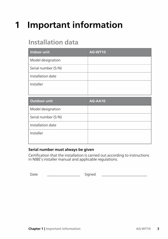
Installation dataAG-WT10Indoor unit
Model designation
Serial number (S/N)
Installation date
Installer
AG-AA10Outdoor unit
Model designation
Serial number (S/N)
Installation date
Installer
Serial number must always be given
Certification that the installation is carried out according to instructionsin NIBE's installer manual and applicable regulations.
_________________________Signed__________________Date
3AG-WT10Chapter 1 | Important information
Safety information
This appliance can be used by children aged from 8years and above and persons with reduced physical,sensory or mental capabilities or lack of experienceand knowledge if they have been given supervision orinstruction concerning use of the appliance in a safeway and understand the hazards involved. Childrenshall not play with the appliance. Cleaning and usermaintenance shall not be made by children withoutsupervision.
Rights to make any design or technical modificationsare reserved.
©NIBE 2015.
Symbols
NOTE
This symbol indicates danger to machine or person.
Caution
This symbol indicates important information about what you shouldobserve when maintaining your installation.
TIP
This symbol indicates tips on how to facilitate using the product.
MarkingThe CEmarkingmeans that NIBE ensures that the product meets all regu-lations that are placed on it based on relevant EU directives. The CE markis obligatory for most products sold in the EU, regardless where they aremade.
AG-WT10Chapter 1 | Important information4
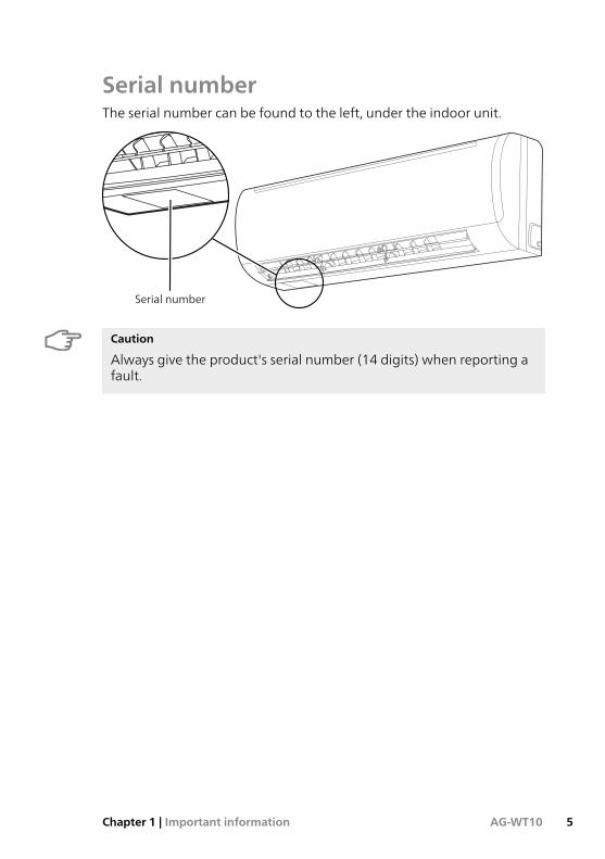
Serial numberThe serial number can be found to the left, under the indoor unit.
Serial number
Caution
Always give the product's serial number (14 digits) when reporting afault.
5AG-WT10Chapter 1 | Important information
AG-WT10 – an excellent choiceAG-WT10 is part of a complete, modern heat pump system that offers ef-fective technical energy saving and reduced carbondioxide emissions. Theintegrated control system in the indoor unit gives safe and economicalclimate control.
The heat is retrieved from the outdoor air by means of an outdoor unit(AG-AA10), where the refrigerant, which circulates in a closed system,transfers the heat from the heat source (the outdoor air) to the indoorunit (AG-WT10).
Excellent properties for AG-WT10:■ iFEEL
The iFEEL function has been developed to obtain the best possiblecomfort. The iFEEL function uses the remote control's integrated tem-perature sensor to adjust the room temperature based on where theremote control is in the room. For best results the remote control shouldbe positioned so that the communication line between the remotecontrol and indoor unit is as direct as possible.
■ Inverter controlled compressor
Theheat pumphas an inverter controlled compressor that automaticallyadapts itself optimally and economically to your home's energy require-ment.
■ Air ioniser
AG-WT10 is equipped with an air ioniser that effectively prevents badair and eliminates bacteria and microorganisms.
■ Night program
With the night program, the temperature and fan speed are adjustedto save energy without affecting the comfort of the premises.
■ High power
With the High Power function activated, the climate unit works at themaximum cooling or heating power.
AG-WT10Chapter 1 | Important information6
Safety instructionsRead this instructionmanual carefully before using the climate unit. In theevent of doubt or problems please consult your dealer.
This climate unit has been designed to create ideal climate conditions inyour room. Only use the unit for this purpose and as described in thismanual.
NOTE■ Avoid the use and storage of flammable liquids near the climate unit.■ Never install electric equipment that does not have IPX1 protection(protection against vertical water drops), under the unit.
■ Donot switch the climate unit on or off using themain switch. Alwaysuse theON/OFFbuttonon the remote control or the function selectoron the unit.
■ Do not allow children to play with the climate unit.■ Donot cool the room toomuch if there are young childrenor disabledpeople in the room.
■ The climate unit is not intended for use by persons (including children)with reduced physical, sensory ormental capabilities, or lack of exper-ience or knowledge, unless they have been instructed by, or are underthe supervision of, a person who is responsible for the safety of theclimate unit when it is in use.
Themanufacturer assumes no liability, if safety the standards or protectionpreventive measures are not complied with.
7AG-WT10Chapter 1 | Important information
RecoveryInformation about correct recycling of theproduct in accord-ance with the EU directive 2012/19/EU
Do not dispose of used units with normal household waste.
It must be disposed of at a special waste station or dealer who providesthis type of service.
Separate waste sorting of an electrical and electronic device makes itpossible toprevent adverse effects on the environment andhumanhealth,which may occur from inappropriate waste sorting and this also makes itpossible to reuse and recycle the material, which leads to a considerablesaving of energy and resources.
To emphasize the need for waste sorting and separate handling of theseunits, there is a symbol of a crossed-out waste bin on the product.
Improper disposal of the product by the user results in administrativepenalties in accordance with current legislation.
AG-WT10Chapter 1 | Important information8
Information about handling used batteries in accordancewith the EU directive 2006/66/EC
Do not dispose of used batteries with household waste.
They must be disposed of at a special waste station or at a dealer whoprovides this type of service.
Separate disposal of batteriesmakes it possible to prevent adverse effectson theenvironment andhumanhealth,whichmayoccur from inappropri-ate waste handling and this also makes it possible to reuse and recyclethematerial, which leads to a considerable savingof energy and resources.
To emphasize the need forwaste sorting and separate handling of batter-ies, there is a symbol of a crossed-out waste bin on the product.
Improper disposal of the product by the user results in administrativepenalties in accordance with current legislation.
9AG-WT10Chapter 1 | Important information
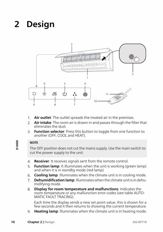
2 Design
1
2
3
456
789
11
10
1. Air outlet: The outlet spreads the treated air in the premises.2. Air intake: The room air is drawn in and passes through the filter that
eliminates the dust.3. Function selector: Press this button to toggle from one function to
another (OFF, COOL and HEAT).
NOTE
The OFF position does not cut the mains supply. Use the main switch tocut the power supply to the unit.
4. Receiver: It receives signals sent from the remote control.5. Function lamp: It illuminates when the unit is working (green lamp)
and when it is in standby mode (red lamp).6. Cooling lamp: Illuminates when the climate unit is in cooling mode.7. Dehumidification lamp: Illuminateswhen the climate unit is in dehu-
midifying mode.8. Display for room temperature and malfunctions: Indicates the
room temperature or any malfunction error codes (see table AUTO-MATIC FAULT TRACING).
Each time the display sends a new set point value, this is shown for afew seconds and it then returns to showing the current temperature.
9. Heating lamp: llluminates when the climate unit is in heating mode.
AG-WT10Chapter 2 | Design10
10. Remote control11. Dehumidification lamp: Illuminateswhen the climate unit is in dehu-
midifying mode.
TIP
The climate unit can be set so that all indicator lamps are always off,even during operation. Perform the following on the remote control:■ Select Air ioniser ( )OFF.■ At the same time, press and for five seconds. Repeat theprocedure to reset to normal mode.
In all fault situations, as read by the climate unit's fault detection system,the indicator lights activate, even if they are set to be off, according tothe fault to be indicated. See section "Fault codes" on page 38 for moreinformation.
11AG-WT10Chapter 2 | Design
3 Remote control
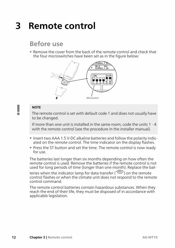
Before use■ Remove the cover from the back of the remote control and check thatthe four microswitches have been set as in the figure below:
Microswitch
NOTE
The remote control is set with default code 1 and does not usually haveto be changed.
If more than one unit is installed in the same room, code the units 1 - 4with the remote control (see the procedure in the installer manual).
■ Insert twoAAA 1.5 V-DC alkaline batteries and follow the polarity indic-ated on the remote control. The time indicator on the display flashes.
■ Press the ST button and set the time. The remote control is now readyfor use.
The batteries last longer than six months depending on how often theremote control is used. Remove the batteries if the remote control is notused for long periods of time (longer than one month). Replace the bat-teries when the indicator lamp for data transfer ( ) on the remotecontrol flashes or when the climate unit does not respond to the remotecontrol command.
The remote control batteries contain hazardous substances. When theyreach the end of their life, they must be disposed of in accordance withapplicable legislation.
AG-WT10Chapter 3 | Remote control12
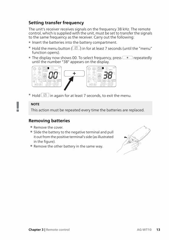
Setting transfer frequencyThe unit's receiver receives signals on the frequency 38 kHz. The remotecontrol, which is suppliedwith the unit, must be set to transfer the signalsto the same frequency as the receiver. Carry out the following:■ Insert the batteries into the battery compartment.■ Hold themenu button ( ) in for at least 7 seconds (until the ”menu”function opens).
■ The display now shows 00. To select frequency, press repeatedlyuntil the number "38" appears on the display.
CC
■ Hold in again for at least 7 seconds, to exit the menu.
NOTE
This action must be repeated every time the batteries are replaced.
Removing batteries■ Remove the cover.■ Slide the battery to the negative terminal and pullit out from thepositive terminal's side (as illustratedin the figure).
■ Remove the other battery in the same way.
13AG-WT10Chapter 3 | Remote control
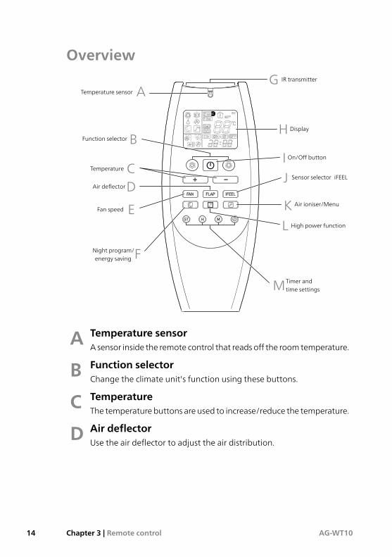
Overview
C
A
D
E
F
C
M
K
JI
H
G
L
B
Temperature sensor
Function selector
Temperature
Air deflector
Fan speed
Night program/energy saving
IR transmitter
On/Off button
Air ioniser/Menu
Sensor selector iFEEL
Display
High power function
Timer andtime settings
Temperature sensorAAsensor inside the remote control that readsoff the roomtemperature.
Function selectorBChange the climate unit's function using these buttons.
TemperatureCThe temperaturebuttons areused to increase/reduce the temperature.
Air deflectorDUse the air deflector to adjust the air distribution.
AG-WT10Chapter 3 | Remote control14
Fan speedThe fan button is used to toggle the fan speed between:■ Automatic fan speed.■ Low fan speed.■ Medium fan speed.■ High fan speed.
E
Night program/energy savingPress this button to select the "Night program/ECO" function. Readmore about the function on page 23.
F
IR transmitterThe IR transmitters transmit the command to the climate unit's receiver.
GDisplayThe display shows operating information when the remote control ison.
H
On/Off buttonStarts or stop the climate unit.
ISensor selector iFEELUse iFEEL to adjust the room temperature according to the remotecontrol position. Read more on page 25.
J
Air ioniser/menuThe air ioniser button is used to:■ Activate the function "Air ioniser.■ Enter the menu functions.
K
High power functionThe High power function maximises the climate unit's heating orcooling power. Read more on page 24.
L
Timer and time settingsUse these buttons to change the timer and time settings.
M
15AG-WT10Chapter 3 | Remote control
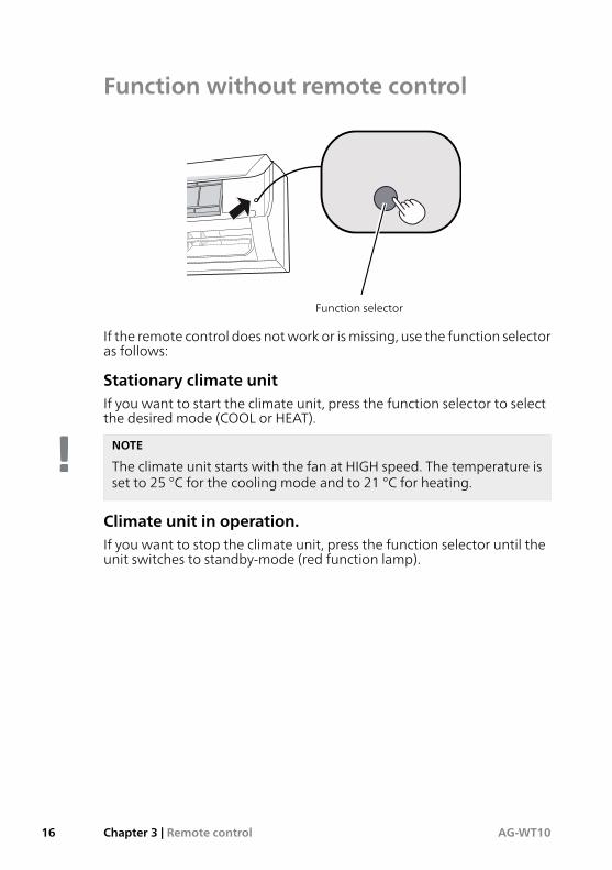
Function without remote control
Function selector
If the remote control does notwork or ismissing, use the function selectoras follows:
Stationary climate unitIf you want to start the climate unit, press the function selector to selectthe desired mode (COOL or HEAT).
NOTE
The climate unit starts with the fan at HIGH speed. The temperature isset to 25 °C for the cooling mode and to 21 °C for heating.
Climate unit in operation.If you want to stop the climate unit, press the function selector until theunit switches to standby-mode (red function lamp).
AG-WT10Chapter 3 | Remote control16
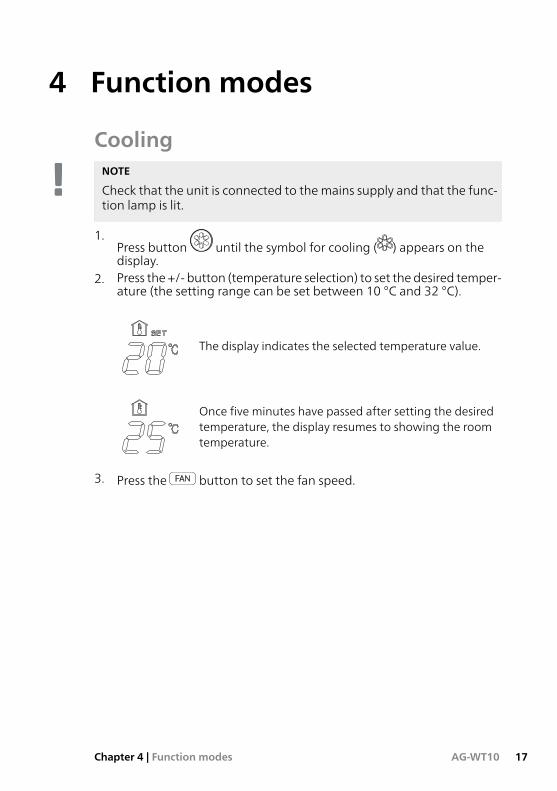
4 Function modes
CoolingNOTE
Check that the unit is connected to themains supply and that the func-tion lamp is lit.
1.Press button until the symbol for cooling ( ) appears on thedisplay.
2. Press the +/- button (temperature selection) to set the desired temper-ature (the setting range can be set between 10 °C and 32 °C).
The display indicates the selected temperature value.
Once five minutes have passed after setting the desiredtemperature, the display resumes to showing the roomtemperature.
3. Press the button to set the fan speed.
17AG-WT10Chapter 4 | Function modes
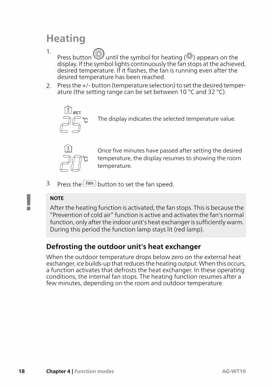
Heating1.
Press button until the symbol for heating ( ) appears on thedisplay. If the symbol lights continuously the fan stops at the achieved,desired temperature. If it flashes, the fan is running even after thedesired temperature has been reached.
2. Press the +/- button (temperature selection) to set the desired temper-ature (the setting range can be set between 10 °C and 32 °C).
The display indicates the selected temperature value.
Once five minutes have passed after setting the desiredtemperature, the display resumes to showing the roomtemperature.
3. Press the button to set the fan speed.
NOTE
After the heating function is activated, the fan stops. This is because the”Prevention of cold air” function is active and activates the fan's normalfunction, only after the indoor unit's heat exchanger is sufficientlywarm.During this period the function lamp stays lit (red lamp).
Defrosting the outdoor unit's heat exchangerWhen the outdoor temperature drops below zero on the external heatexchanger, icebuilds-up that reduces theheatingoutput.When this occurs,a function activates that defrosts the heat exchanger. In these operatingconditions, the internal fan stops. The heating function resumes after afew minutes, depending on the room and outdoor temperature.
AG-WT10Chapter 4 | Function modes18
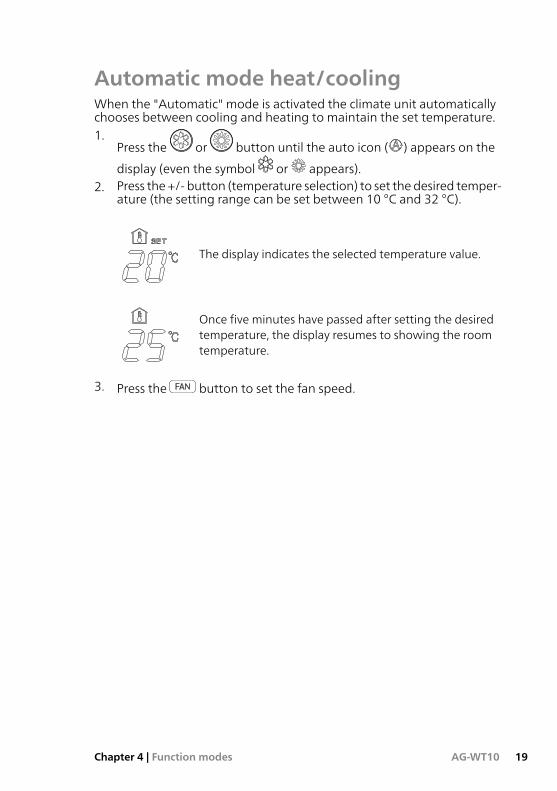
Automatic mode heat/coolingWhen the "Automatic" mode is activated the climate unit automaticallychooses between cooling and heating to maintain the set temperature.1.
Press the or button until the auto icon ( ) appears on the
display (even the symbol or appears).2. Press the +/- button (temperature selection) to set the desired temper-
ature (the setting range can be set between 10 °C and 32 °C).
The display indicates the selected temperature value.
Once five minutes have passed after setting the desiredtemperature, the display resumes to showing the roomtemperature.
3. Press the button to set the fan speed.
19AG-WT10Chapter 4 | Function modes
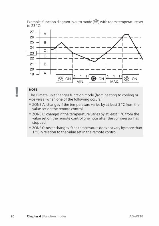
Example: function diagram in automode ( ) with room temperature setto 23 °C:
ONON ON∆ 1 H ∆ 1 H
MIN. MAX.
A
B
C
C
B
A
27
26
25
24
23
22
21
20
19
NOTE
The climate unit changes function mode (from heating to cooling orvice versa) when one of the following occurs:■ ZONE A: changes if the temperature varies by at least 3 °C from thevalue set on the remote control.
■ ZONE B: changes if the temperature varies by at least 1 °C from thevalue set on the remote control one hour after the compressor hasstopped.
■ ZONEC: never changes if the temperature does not vary bymore than1 °C in relation to the value set in the remote control.
AG-WT10Chapter 4 | Function modes20
Dehumidification1.
Press button until the symbol for dehumidifying ( ) appears onthe display.
2. Press the +/- button (temperature selection) to set the desired temper-ature (the setting range can be set between 10 °C and 32 °C).
The display indicates the selected temperature value.
Once five minutes have passed after setting the desiredtemperature, the display resumes to showing the roomtemperature.
■ When the room temperature is above the set value the heat pumpworks automatically to dehumidify as effectively as possible.
■ When the room temperature is below the set value, the heat pumpstillworks at lowpower to continuedehumidificationandcan reducethe room temperature in small spaces to 10 °C.
NOTE■ Use the dehumidification function to reduce the air humidity in theroom.
■ When the room temperature reaches the set value, the climate unitrepeats on and off cycles in automatic mode.
■ In dehumidifying mode the fan speed is set automatically.■ The defrosting function does not work at room temperatures below10 °C.
21AG-WT10Chapter 4 | Function modes
VentilationIf only air circulation is required in the premises, without changing the
temperature, press the button until the function mode window onthe display is empty. The fan speed is controlled by the button.
Function in the event of power cutThe climate unit stops in the event of a power cut. When the electricalsupply is restored, the climate unit restarts automatically after threeminutes.
AG-WT10Chapter 4 | Function modes22
5 Operating program
Air ioniserPress the button (the symbol appears in the display) to activatethe air ioniser, which effectively prevents bad odours and eliminates bac-teria and microorganisms.
NOTE
The device is only active if the inner fan is working.
Night program/energy savingIf the night program is selected, the climate unit automatically changesthe set temperature 60minutes after selection. In thisway, energy is savedwithout risking the comfort of the premises. During the night program,the fan speed is automatically reduced making it quieter.1.
Press the button or to set the climate unit for cooling, dehu-midifying or heating.
2. Press the button. The symbol appears in the display.3. To exit the program, press again.
Temperature changeFunction mode
Reduces by 2 °CHeating
Increases by 1 °CCooling and dehumidifying
23AG-WT10Chapter 5 | Operating program
High power-programWhen this option is active, the fan speed is set automatically and the cli-mate unit works at full cooling or heating power. High Power is activeuntil this function is switched off using the HIGH POWER button.
NOTE
In HIGHPOWERmode, the temperature of the premisesmay not corres-pond with the set temperature.
AG-WT10Chapter 5 | Operating program24
iFEEL/iFEEL CiFEELC is not available on thismodel.When selected, the functionbecomesthe same as iFEEL. In the remote control there is a iFEEL sensor thatmakesit possible to adjust the temperature based on where in the room the re-mote control is located, for optimum comfort. The iFEEL function worksvia signal transfer from the remote control to the indoor module, via twotransmitters with IR LEDs. The LEDs have a large scatter angle, which givesgood roomcoverage. Therefore, the remote control seldomneedspointingdirectly at the indoor module, which is usually the case with remote con-trols, e.g. TVs and consumer electronic products. However, the IR signalcanbe interruptedorpartially absorbedbydifferent environmental factors,e.g.:■ fluorescent lighting■ sunlight■ high humidity■ IR generated heat sources■ presence of many people or animals■ certain building, interior and furniture material■ size and shape of structures and objects in the environment■ reflection and/or partial absorption of the IR signal
It is therefore appropriate to position the remote control so that thecommunication line between the remote control and indoor unit is asdirect as possible. If correct signal transfer is not possible, adjust the tem-perature from the indoor module's sensor.
In such cases, the desired temperature (set temperature) can deviate fromthe temperature shown on the remote control, due to the stratificationof the air in the room (cooler air near the floor and warmer near the ceil-ing), especially if the indoor unit is wall mounted.
Hot air rises.When iFEEL is disconnected, or the remote control cannot beread by the indoor unit, such stratification can cause the indoor moduletodetect ahigh temperature that only exists locally, and, therefore, appearsto regulate incorrectly.
In such cases, simply increase the set desired temperature on the remotecontrol until the actual temperature is comfortable.
25AG-WT10Chapter 5 | Operating program
6 Fan and air flow setting
Selecting fan speedAutomatic mode
Set automatic fan mode ( ) using the push button. The micro-processor automatically controls the fan speed.When the climate controlstarts towork, in heating or coolingmode, the fan speed varies (low-high)in accordance with the room temperature.
NOTE
Theautomatic speed cannotbe selected in functionmode "ventilation".
Manual mode
To manually regulate the fan speed, press the button and select thedesired speed:
High speedMedium speedLow speed
AG-WT10Chapter 6 | Fan and air flow setting26
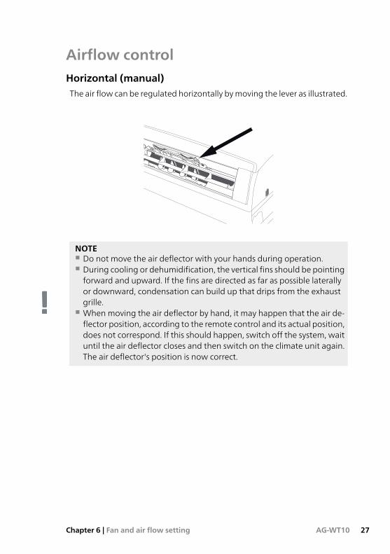
Airflow controlHorizontal (manual)The air flow can be regulated horizontally bymoving the lever as illustrated.
NOTE■ Do not move the air deflector with your hands during operation.■ During cooling or dehumidification, the vertical fins should be pointingforward and upward. If the fins are directed as far as possible laterallyor downward, condensation can build up that drips from the exhaustgrille.
■ Whenmoving the air deflector by hand, it may happen that the air de-flector position, according to the remote control and its actual position,does not correspond. If this should happen, switch off the system, waituntil the air deflector closes and then switch on the climate unit again.The air deflector's position is now correct.
27AG-WT10Chapter 6 | Fan and air flow setting
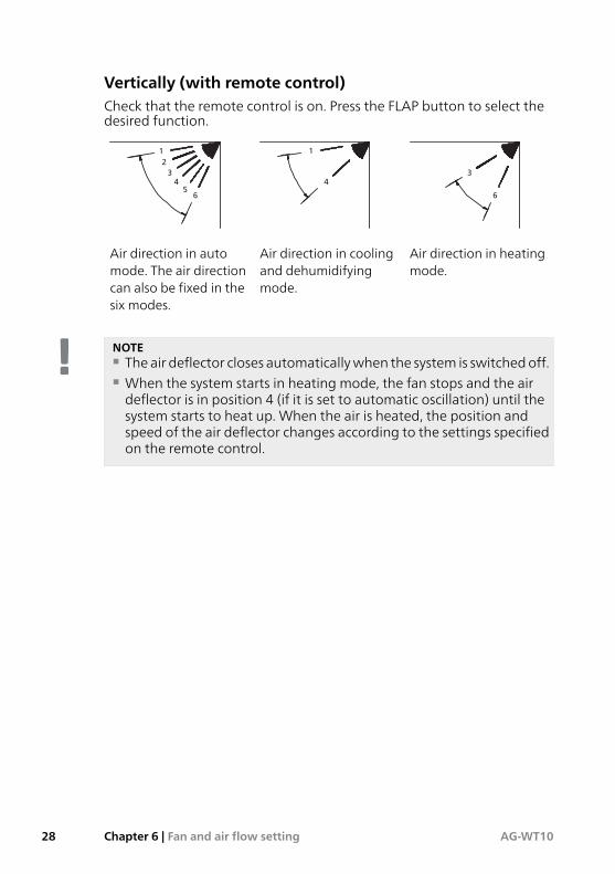
Vertically (with remote control)Check that the remote control is on. Press the FLAP button to select thedesired function.
3
6
1
4
12
34
56
Air direction in heatingmode.
Air direction in coolingand dehumidifyingmode.
Air direction in automode. The air directioncan also be fixed in thesix modes.
NOTE■ The air deflector closes automaticallywhen the system is switchedoff.■ When the system starts in heating mode, the fan stops and the airdeflector is in position 4 (if it is set to automatic oscillation) until thesystem starts to heat up. When the air is heated, the position andspeed of the air deflector changes according to the settings specifiedon the remote control.
AG-WT10Chapter 6 | Fan and air flow setting28
7 Clock and timer
Setting the clock1. Press the ST button three times. The time indicator starts to flash.2. Press button H until the desired time is shown. Press button M until
the desiredminutes are shown. The time indicator on thedisplay stopsflashing automatically after 10 seconds.
Setting the timerStart time (ON)
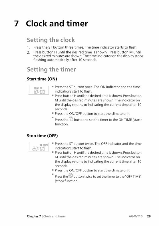
■ Press the ST button once. The ON indicator and the timeindications start to flash.
■ Press buttonHuntil thedesired time is shown. Press buttonM until the desired minutes are shown. The indicator onthe display returns to indicating the current time after 10seconds.
■ Press the ON/OFF button to start the climate unit.■ Press the button to set the timer to the ON TIME (start)function.
Stop time (OFF)
■ Press the ST button twice. The OFF indicator and the timeindications start to flash.
■ Press buttonHuntil thedesired time is shown. Press buttonM until the desired minutes are shown. The indicator onthe display returns to indicating the current time after 10seconds.
■ Press the ON/OFF button to start the climate unit.■ Press the button twice to set the timer to the "OFF TIME"(stop) function.
29AG-WT10Chapter 7 | Clock and timer
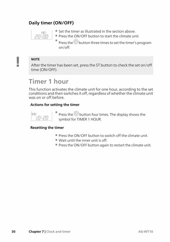
Daily timer (ON/OFF)
■ Set the timer as illustrated in the section above.■ Press the ON/OFF button to start the climate unit.■ Press the button three times to set the timer's programon/off.
NOTE
After the timer has been set, press the ST button to check the set on/offtime (ON/OFF).
Timer 1 hourThis function activates the climate unit for one hour, according to the setconditions and then switches it off, regardless ofwhether the climate unitwas on or off before.
Actions for setting the timer
■ Press the button four times. The display shows thesymbol for TIMER 1 HOUR.
Resetting the timer
■ Press the ON/OFF button to switch off the climate unit.■ Wait until the inner unit is off.■ Press the ON/OFF button again to restart the climate unit.
AG-WT10Chapter 7 | Clock and timer30
Vacation timerThe "vacation timer" functions makes it possible to activate the indoorunit, with a programmable delay of up to 99 days regarding the functionsof the daily timer, On-timer, Off-timer (does not apply to TIMER 1 HOUR)as previously described in this manual. With this function it is possible toprogram a climate unit restart after a public holiday, a vacation of one ortwo weeks etc. This timer works as follows:■ Start time:
After x number of days, the climate unit starts with the set values andcontinues until another setting is made.
■ Stop time:
The climate unit runs according to settings in x number of days, it thenstops.
■ Daily timer:
First set times in ”daily timer”. After x number of days, themachine startsand runs according to the timer settings each day until another settingis made.
To activate the function, follow the steps below in order:1. Hold the button in on the remote control for at least 6 – 7
seconds. When the button is released, the menu for selecting thenumber of days the delay is to apply for appears.
2. Select desired timer (daily timer, start time, stop time) and press thesame button .
3. Set the desired number of delayed days using ”+”.4. Hold the button in on the remote control again for at least 6 – 7
seconds.When thebutton is released, youare returned to thenormalmenu on the remote control.
The icon for the desired timer now starts to flash and the correspondingtimer activates, according to the set number of days delay.
31AG-WT10Chapter 7 | Clock and timer
8 Care and maintenance
Regular checksYour heat pump is, in principle, maintenance free and therefore requiresminimal care after commissioning. On the other hand, it is recommendedthat you check your installation regularly.
If something unusual occurs, messages about the malfunction appear inthe display in the formof alarm codes on the indoor unit display. See errorcode table on page 38.
NOTE■ Aside from regular cleaning,maintenance actionsmust beperformedby service technicians.
■ Check that the climate unit is off and that the mains supply is discon-nected, before carrying out further cleaning work.
■ Do not pour water onto the indoor unit during cleaning. This candamage the internal parts of the unit and cause short-circuits.
Housing and grilleClean the inner casing and grille of the unit with a vacuum cleaner brush,or with a soft and dry cloth. If there are any spots on these parts, use adamp cloth with a small amount of cleaning agent.
Caution■ Donotuseany solvents, cleaningagentsor strong chemical substances.Do not use boiling water to clean the indoor unit.
■ Some metal edges and fins on the climate unit are sharp. Take greatcare when cleaning these.
■ The heat exchanger and other components on the outdoor unit mustbe cleaned at least once a year. Contact installer.
AG-WT10Chapter 8 | Care and maintenance32
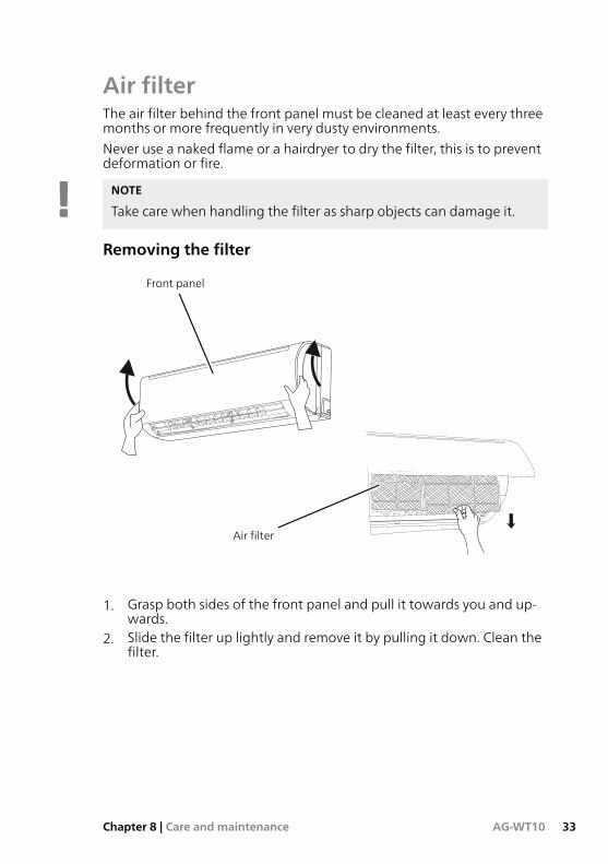
Air filterThe air filter behind the front panel must be cleaned at least every threemonths or more frequently in very dusty environments.
Never use a naked flame or a hairdryer to dry the filter, this is to preventdeformation or fire.
NOTE
Take care when handling the filter as sharp objects can damage it.
Removing the filter
Front panel
Air filter
1. Grasp both sides of the front panel and pull it towards you and up-wards.
2. Slide the filter up lightly and remove it by pulling it down. Clean thefilter.
33AG-WT10Chapter 8 | Care and maintenance
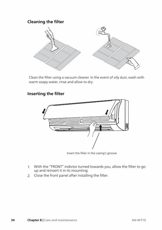
Cleaning the filter
Clean the filter using a vacuum cleaner. In the event of oily dust, wash withwarm soapy water, rinse and allow to dry.
Inserting the filter
Insert the filter in the casing's groove
1. With the “FRONT” indictor turned towards you, allow the filter to goup and reinsert it in its mounting.
2. Close the front panel after installing the filter.
AG-WT10Chapter 8 | Care and maintenance34
Advice formaximumcomfort and lowestenergy consumptionAvoid:■ To block the exhaust and intake grilles on the unit, if they are blockedthe function is impaired and damage may be caused.
Check:■ That the filter is always clean. A dirty filter reduces the air exchange andreduces the unit's capacity.
■ That doors andwindows are closed to prevent non-conditioned air fromentering.
35AG-WT10Chapter 8 | Care and maintenance
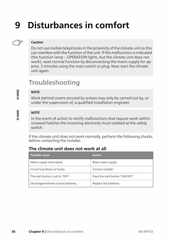
9 Disturbances in comfort
Caution
Donot usemobile telephones in the proximity of the climate unit as thiscan interferewith the function of the unit. If thismalfunction is indicated(the function lamp – OPERATION lights, but the climate unit does notwork), reset normal function by disconnecting the mains supply for ap-prox. 3 minutes using the main switch or plug. Now start the climateunit again.
TroubleshootingNOTE
Work behind covers secured by screws may only be carried out by, orunder the supervision of, a qualified installation engineer.
NOTE
In the event of action to rectify malfunctions that require work withinscrewed hatches the incoming electricity must isolated at the safetyswitch.
If the climate unit does not work normally, perform the following checks,before contacting the installer.
The climate unit does not work at allActionPossible cause
Reset mains supply.Mains supply interrupted.
Contact installer.Circuit fuse blown or faulty.
Press the start button "ON/OFF".The start button is set to "OFF".
Replace the batteries.Discharged remote control batteries.
AG-WT10Chapter 9 | Disturbances in comfort36
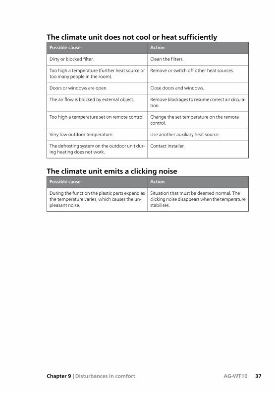
The climate unit does not cool or heat sufficientlyActionPossible cause
Clean the filters.Dirty or blocked filter.
Remove or switch off other heat sources.Too high a temperature (further heat source ortoo many people in the room).
Close doors and windows.Doors or windows are open.
Removeblockages to resume correct air circula-tion.
The air flow is blocked by external object.
Change the set temperature on the remotecontrol.
Too high a temperature set on remote control.
Use another auxiliary heat source.Very low outdoor temperature.
Contact installer.The defrosting systemon the outdoor unit dur-ing heating does not work.
The climate unit emits a clicking noiseActionPossible cause
Situation that must be deemed normal. Theclickingnoisedisappearswhen the temperaturestabilises.
During the function the plastic parts expand asthe temperature varies, which causes the un-pleasant noise.
37AG-WT10Chapter 9 | Disturbances in comfort
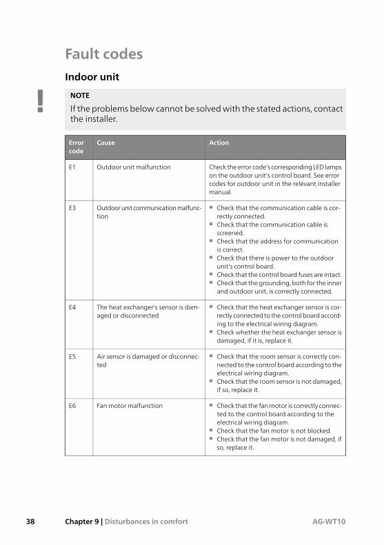
Fault codesIndoor unit
NOTE
If the problems below cannot be solvedwith the stated actions, contactthe installer.
ActionCauseErrorcode
Check theerror code's correspondingLED lampson the outdoor unit's control board. See errorcodes for outdoor unit in the relevant installermanual.
Outdoor unit malfunctionE1
■ Check that the communication cable is cor-rectly connected.
■ Check that the communication cable isscreened.
■ Check that the address for communicationis correct.
■ Check that there is power to the outdoorunit's control board.
■ Check that the control board fuses are intact.■ Check that the grounding, both for the inner
and outdoor unit, is correctly connected.
Outdoorunitcommunicationmalfunc-tion
E3
■ Check that the heat exchanger sensor is cor-rectly connected to the control board accord-ing to the electrical wiring diagram.
■ Check whether the heat exchanger sensor isdamaged, if it is, replace it.
The heat exchanger's sensor is dam-aged or disconnected
E4
■ Check that the room sensor is correctly con-nected to the control board according to theelectrical wiring diagram.
■ Check that the room sensor is not damaged,if so, replace it.
Air sensor is damaged or disconnec-ted
E5
■ Check that the fanmotor is correctly connec-ted to the control board according to theelectrical wiring diagram.
■ Check that the fan motor is not blocked.■ Check that the fan motor is not damaged, if
so, replace it.
Fan motor malfunctionE6
AG-WT10Chapter 9 | Disturbances in comfort38
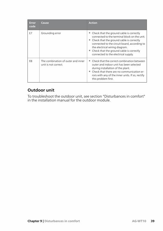
ActionCauseErrorcode
■ Check that the ground cable is correctlyconnected to the terminal block on the unit.
■ Check that the ground cable is correctlyconnected to the circuit board, according tothe electrical wiring diagram.
■ Check that the ground cable is correctlyconnected to the electrical supply.
Grounding errorE7
■ Check that the correct combinationbetweenouter and indoor unit has been selectedduring installation of the plant.
■ Check that there are no communication er-rors with any of the inner units. If so, rectifythis problem first.
The combination of outer and innerunit is not correct.
E8
Outdoor unitTo troubleshoot the outdoor unit, see section "Disturbances in comfort"in the installation manual for the outdoor module.
39AG-WT10Chapter 9 | Disturbances in comfort
Item register
AAir filter, 33Airflow control, 27Air ioniser, 23Automatic mode heat/cooling, 19
CCare and maintenance, 32
Air filter, 33Housing and grille, 32Regular checks, 32
Clock and timer, 29Daily timer, 30Start time, 29Stop time, 29Timer 1 hour, 30Vacation timer, 31
Cooling, 17
DDehumidification, 21Disturbances in comfort, 36
Fault codes, 38Troubleshooting, 36
FFan and airflow settings, 26
Airflow control, 27Fan speed, 26
Fan speed, 26Fault codes, 38Function in the event of power cut, 22Function modes, 17
Automatic mode heat/cooling, 19Cooling, 17Defrosting, 18Dehumidification, 21Function in the event of powercut, 22Heating, 18
Ventilation, 22Function without remote control, 16
HHeating, 18High power-program, 24
IiFEEL/iFEEL C, 25Important information, 3
AG-WT10 – an excellent choice, 6Installation data, 3Recovery, 8Safety information, 4Serial number, 5
Indoor unit's design, 10Installation data, 3
NNight program/energy saving, 23
OOperating program, 23
Air ioniser, 23High power-program, 24iFEEL/iFEEL C, 25Night program/energy saving, 23
RRemote control, 12
Before use, 12Overview, 14
SSerial number, 5
TTroubleshooting, 36
VVentilation, 22
AG-WT10Chapter 10 | Item register40
10