Embed Size (px)
Citation preview
Indoor Information Support System Using Optical Wireless Communications Technique
XIN LIN1, KAZUTAKA KOSUGI2, and HIDEO ITOH1
1Information Technology Research Institute, AIST 2-41-6 Aomi, Koto-ku, Tokyo 135-0064
JAPAN [email protected]
2Faculty of Science and Technology, Seikei University Musashino-shi, Tokyo 180-8633
JAPAN Abstract: - Optical wireless communications system with a corner-reflecting terminal and a distance image camera is proposed for location-based information support. By using the corner-reflecting terminal and the distance image camera, the user location can be tracked and detected, and the distance from the camera to the user who is tracked can be obtained real-timely. Therefore, the information support of users can be implemented based only on their physical locations and without the private data such as an address or ID number. We also performed several experiments based on the proposed system and method, and their effectiveness is demonstrated in multi-terminal location detection and indoor data communications. Key-Words: - Optical wireless communication; Location based; Corner-reflecting terminal; Distance image camera; Three-dimensional location detection; User information support. 1 Introduction Wireless communication has become a ubiquitous part of modern life from global telephone systems to local and personal-area networks [1]-[5]. The method of location-based optical wireless communication is based on the physical location information of the user and by using spatial optical wave as the carrier to do data transmission in an indoor environment. Its attractive features are adequate privacy protection because the data transmissions are based only on the user’s location, without the need for a user address, user ID, etc., and information contents safety by the directionality of light beams [6]-[9].
In order to realize the location-based information support, the location information of the terminal and user’s messages that are carried by it must be detected simultaneously. In the previous papers [10], [11], we have proposed a method for location detection and message recognition using a general video camera with an infrared LED ring and an infrared bandpass filter. In that method, the video image of the terminal is first captured by the camera, and then, the location information is obtained based on the pattern-matching technique to measure the shape similarity between an idealized representation of a feature and a feature that may be present in the
terminal image. However the distance information of users cannot be grasped real-timely.
As an alternative or more efficient method to realize the location-based optical wireless communications, we consider to using a distance image camera (DIC), which can simultaneously take the brightness and the distance of an object to locate users three-dimensionally in this paper. The DIC also can as a light source to transmit information for optical wireless communications because it with a built-in LED array.
On the other hand, a corner-reflecting terminal (CRT) with a polymer networked liquid crystal (PNLC) panel and a piezoelectric device is developed instead of the previous terminal with a twisted nematic liquid crystal (TNLC) panel [12]-[14], because the frequency response of the TNLC is still inadequate in some applications for high-speed information communications. Whereas, a PNLC modulator can transmit data for several tens bits per second and has good vision acuity [15], [16], these properties make it easy to apply in the optical modulation, carrier and communication techniques employed in the terminal.
Using the proposed location-based communications system and method, we have performed two experiments based on the previous video-based optical wireless communication
WSEAS TRANSACTIONS on COMMUNICATIONS
Xin Lin, Kazutaka Kosugi, and Hideo Itoh
ISSN: 1109-2742327
Issue 4, Volume 7, April 2008
technique [11], and their effectiveness is demonstrated in multi-terminal location detection and indoor information services. 2 Principles of the Method The main elements in proposed optical wireless communication system are the DIC and the CRT. The detail on their structures, principles, and data-transmission functions will be described in Sec. 2.1 and Sec. 2.2 as follows, respectively. 2.1 Distance Image Camera
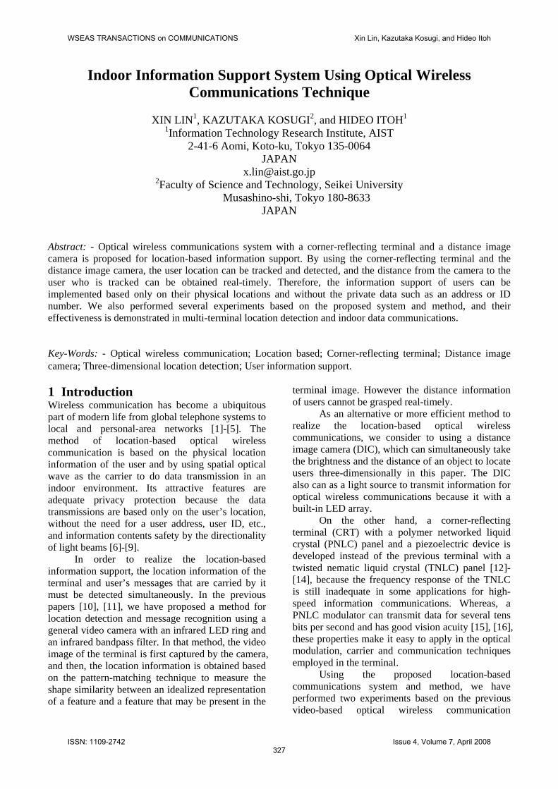
Fig. 1 The distance image camera (DIC).
Fig. 2 Schematic structure and measurement principle of the DIC. Figure 1 is an exterior of the DIC (Matsushita Electric Works E15-04-019). It consists of an LED array illuminator with infrared irradiation of 850nm wavelength, a phase-difference-detection CCD array of 128x123 pixels with a response speed of 15 frames per second, and a functions control unit.
The principle for distance measurement by using the DIC is based on the time-of-flight (TOF) technique, as shown in Fig. 2. In this method, we let c is the optical speed, and t is a detected time (or phase) delay between incident light from irradiation LEDs and reflecting light from an object to the CCD array, then the optical path is defined as . And the distance from the object to the DIC is obtained by . Fig. 3 Examples of image output: (a) chiaroscuro image, (b) distance, and (c) range limitation.
Figure 3 is examples of images output and Three-dimensional location detection. A chiaroscuro image is shown in Fig. 3(a). For example, for a test point O, X and Y are its plane coordinates, Z is its distance to the camera, and B is its brightness value. Figure 3(b) is the distance image of the Fig. 3(a). It uses the color level to denote distances. In this case, the distance pattern is given by the gradient colors from red to blue. The maximum measurement range is 7.5m. Figure 3(c) is a range limitation image of the Fig. 3(a). We can see that only the pattern, which the distance for 1.2m is display when the range limitation is chosen at 1.5m. 2.2 Corner Reflecting Terminal As a more efficient communications terminal to user information support, we developed the CRT with a PNLC light modulator and a piezoelectric signal generator is instead of the previous terminal using a modified PDA (Personal Data Assistant).
Figure 4 shows the PNLC device that is used in our terminal equipment and its principle of optical modulation. The modulation of the output light occurs in 6μm thick layer of liquid crystal material laminated between two pieces of glass plates with a transparent indium tin oxide (ITO) electrode.
When no electric field is applied on the PNLC panel (off state), the liquid crystal molecules are randomly aligned and the incident light is scattered. Consequently, the panel likes a frosted glass and becomes a translucent window, as shown in Fig. 4(a). When enough electric field is applied
imaging lens Distance L = d / 2
irradiation LEDλ = 850nm
incident light
reflected light
z
9 (a)
range: 0 – 1.5m(b) (c)
1 5x=87 y=58 z=2.11 B=123
yx
O
m
1.2m
LED array(850nm)
Distance measurement principle: time of flight
CCD array
optical path d = c・tarrival time t
incident light
reflected lighttime
・・・
・・・・・・
・・・
・・・
・・・
・・・
128×123 pixel
WSEAS TRANSACTIONS on COMMUNICATIONS Xin Lin, Kazutaka Kosugi, and Hideo Itoh
ISSN: 1109-2742328
Issue 4, Volume 7, April 2008
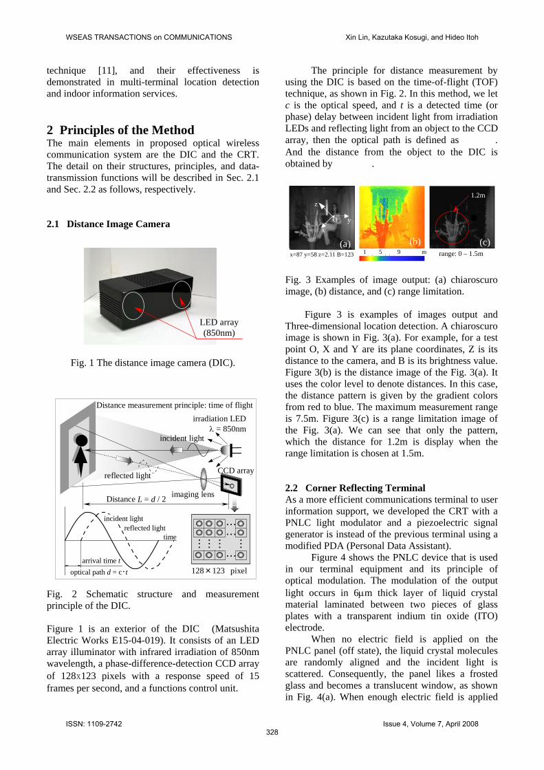
on it (on state), the liquid crystal molecules are aligned in the electric-field direction and the light can path through the panel. In this state, the liquid crystal panel becomes a clear window with small scattering, as shown in Fig. 4(b). Thus, transparent light intensity can be switched by using the applied voltage without using external polarizer like the TNLC light modulators. This modulation property makes it higher brightness to display information.
Operational voltage of the PNLC device is less than 3V when its thickness of the liquid crystal layer is 6μm. This value is lower than the polymer dispersed liquid crystal (PDLC) [17], it make the PNLC device easy to realize low power consumption.
(a)
(b) Fig. 4 Principle of light transmission for a PNLC device: (a) off state and (b) on state.
The structure of proposed terminal is shown in Fig. 5(a). In order to turn the terminal into a corner-reflecting device, we embed a corner-reflection sheet behind PNLC panel. The detail on the principle of the corner-reflecting sheet has been described in our previous paper [7]. The piezoelectric signal generator (Taiheiyo Cement Corporation) is used to drive the PNLC light modulator and generate a pulse signal to control and select the communication signals without using battery or conventional power source. The piezoelectric device is a mechanical/electrical converter that converts mechanical distortion such as a vibration or pressure into voltage. This function
is important for a mobile terminal to realize low power consumption.
corner cube prism
PNLC light modulator with the corner-cube-array sheet
piezoelectric signal generator
(a)
PNLC C
4.7μF
R1 47.5KΩ
R3 4.7KΩ
R247.5KΩ
RC integration circuit
Piezoelectric signal generator
translucent
random LC molecules
(b)
0 1 2 3 4
0
3
6
9
12
5
Vol
tage
(V)
Time (s)
without integration circuit with integration circuit
clear
aligned LC molecules
(c) Fig. 5 Structure and operation principle for the terminal: (a) basic structure consists of PNLC panel with the corner-cube-array sheet that employs the imaging principle of a corner-cube prism and the piezoelectric signal generator, (b) simplified schematic of operation circuit and (c) piezoelectric switching characteristic of the operation circuit.
On the other hand, to obtain a unique trigger pulse to control the PNLC light modulator when pushing a button at the piezoelectric equipment panel only one time, a RC (resistance-condenser) integration circuit is connected parallel with the PNLC light modulator, as shown in Fig.5 (b). Figure
WSEAS TRANSACTIONS on COMMUNICATIONS Xin Lin, Kazutaka Kosugi, and Hideo Itoh
ISSN: 1109-2742329
Issue 4, Volume 7, April 2008
5(c) is dependences of piezoelectric voltage on connection circuits. The abscissa is piezoelectric times and the ordinate is piezoelectric voltage values. We can see that occurring two sharp peak voltage as the broken line when without using the integration circuit. But by using the RC integration circuit, the output voltage is gradually changing as the solid line. 2.3 Location-based Optical Wireless
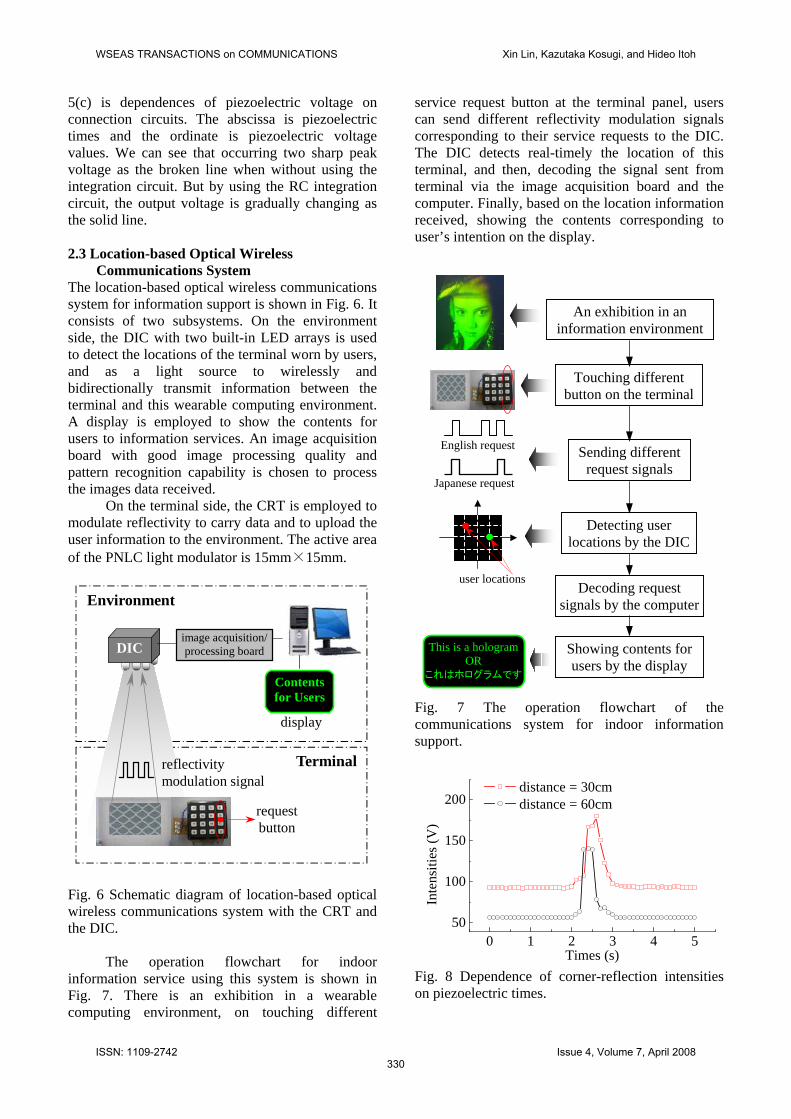
Communications System The location-based optical wireless communications system for information support is shown in Fig. 6. It consists of two subsystems. On the environment side, the DIC with two built-in LED arrays is used to detect the locations of the terminal worn by users, and as a light source to wirelessly and bidirectionally transmit information between the terminal and this wearable computing environment. A display is employed to show the contents for users to information services. An image acquisition board with good image processing quality and pattern recognition capability is chosen to process the images data received.
On the terminal side, the CRT is employed to modulate reflectivity to carry data and to upload the user information to the environment. The active area of the PNLC light modulator is 15mm×15mm. Fig. 6 Schematic diagram of location-based optical wireless communications system with the CRT and the DIC.
The operation flowchart for indoor
information service using this system is shown in Fig. 7. There is an exhibition in a wearable computing environment, on touching different
service request button at the terminal panel, users can send different reflectivity modulation signals corresponding to their service requests to the DIC. The DIC detects real-timely the location of this terminal, and then, decoding the signal sent from terminal via the image acquisition board and the computer. Finally, based on the location information received, showing the contents corresponding to user’s intention on the display.
An exhibition in an
information environment Fig. 7 The operation flowchart of the communications system for indoor information support. Fig. 8 Dependence of corner-reflection intensities on piezoelectric times.
Environment
display
Contents for Users
DIC
Terminalreflectivity modulation signal
image acquisition/ processing board
request button
This is a hologramOR
これはホログラムです
Touching different button on the terminal
Sending different request signals
Detecting user locations by the DIC
Decoding request signals by the computer
English request
Japanese request
user locations
Showing contents for users by the display
0 1 2 3 4 550
100
150
200
Inte
nsiti
es (V
)
Times (s)
distance = 30cm distance = 60cm
WSEAS TRANSACTIONS on COMMUNICATIONS Xin Lin, Kazutaka Kosugi, and Hideo Itoh
ISSN: 1109-2742330
Issue 4, Volume 7, April 2008
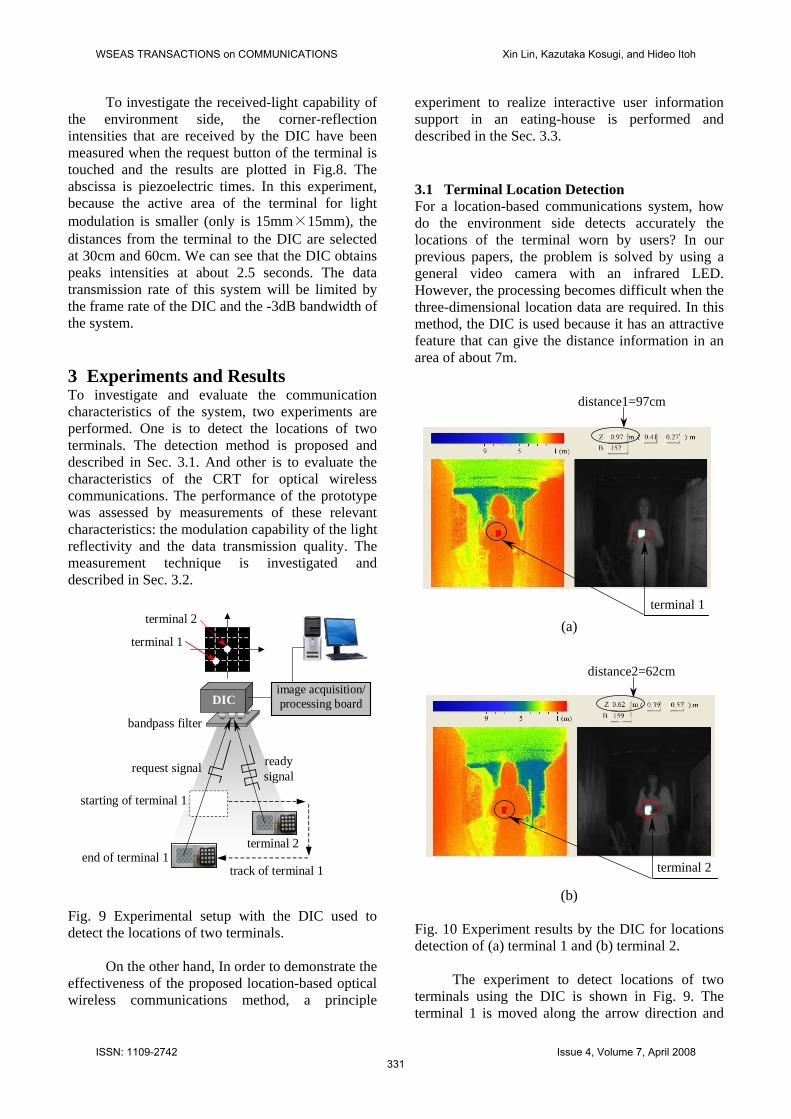
To investigate the received-light capability of the environment side, the corner-reflection intensities that are received by the DIC have been measured when the request button of the terminal is touched and the results are plotted in Fig.8. The abscissa is piezoelectric times. In this experiment, because the active area of the terminal for light modulation is smaller (only is 15mm×15mm), the distances from the terminal to the DIC are selected at 30cm and 60cm. We can see that the DIC obtains peaks intensities at about 2.5 seconds. The data transmission rate of this system will be limited by the frame rate of the DIC and the -3dB bandwidth of the system. 3 Experiments and Results To investigate and evaluate the communication characteristics of the system, two experiments are performed. One is to detect the locations of two terminals. The detection method is proposed and described in Sec. 3.1. And other is to evaluate the characteristics of the CRT for optical wireless communications. The performance of the prototype was assessed by measurements of these relevant characteristics: the modulation capability of the light reflectivity and the data transmission quality. The measurement technique is investigated and described in Sec. 3.2. Fig. 9 Experimental setup with the DIC used to detect the locations of two terminals.
On the other hand, In order to demonstrate the effectiveness of the proposed location-based optical wireless communications method, a principle
experiment to realize interactive user information support in an eating-house is performed and described in the Sec. 3.3. 3.1 Terminal Location Detection For a location-based communications system, how do the environment side detects accurately the locations of the terminal worn by users? In our previous papers, the problem is solved by using a general video camera with an infrared LED. However, the processing becomes difficult when the three-dimensional location data are required. In this method, the DIC is used because it has an attractive feature that can give the distance information in an area of about 7m.
(a) terminal 1
distance1=97cm
distance2=62cm
terminal 2
image acquisition/ processing board
terminal 1
terminal 2
request signal
end of terminal 1 track of terminal 1
terminal 2
DIC
ready signal
starting of terminal 1
bandpass filter
(b)
Fig. 10 Experiment results by the DIC for locations detection of (a) terminal 1 and (b) terminal 2.
The experiment to detect locations of two terminals using the DIC is shown in Fig. 9. The terminal 1 is moved along the arrow direction and
WSEAS TRANSACTIONS on COMMUNICATIONS Xin Lin, Kazutaka Kosugi, and Hideo Itoh
ISSN: 1109-2742331
Issue 4, Volume 7, April 2008
the broken line is its move track. The starting and end from the camera to the terminal 1 are 50cm and 100cm, respectively. The terminal 2 is put at distance of about 60cm from the DIC. Because the terminals are corner-reflection devices, when their are illuminated by the built-in LED array of the DIC, only the signal light that is carried by the terminals will be reflected intensively to the DIC, thus making they easy to extract terminal patterns from background noises. In addition, a bandpass filter that is adapted to the wavelength of the built-in LED is placed before the entrance window of the DIC. Hence, the effect of the noise from the environment illumination can be obviated. Once a terminal is captured, the DIC calculates its distances, which every move point by the phase-difference-detection CCD array based on the TOF technique and output the distance image, as shown in Fig. 10. We can see that the three-dimensional locations data are detected well for two terminals. Fig. 11 Experimental result for Three-dimensional location tracks of two terminals
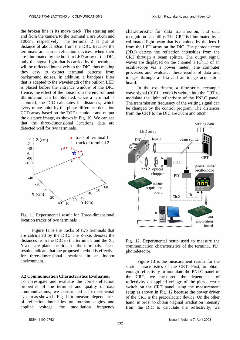
Figure 11 is the tracks of two terminals that are calculated by the DIC. The Z-axis denotes the distances from the DIC to the terminals and the X-, Y-axis are plane locations of the terminals. These results indicate that the proposed method is effective for three-dimensional locations in an indoor environment. 3.2 Communication Characteristics Evaluation To investigate and evaluate the corner-reflection properties of the terminal and quality of data communications, we constructed an experimental system as shown in Fig. 12 to measure dependences of reflection intensities on rotation angles and applied voltage, the modulation frequency
characteristic for data transmission, and data recognition capability. The CRT is illuminated by a collimated light beam that is obtained by the lens 1 from the LED array on the DIC. The photodetector (PD1) detects the reflection intensities from the CRT through a beam splitter. The output signal waves are displayed on the channel 1 (Ch.1) of an oscilloscope via a power meter. The computer processes and evaluates these results of data and images through a data and an image acquisition board.
In the experiment, a time-series rectangle wave signal (0101…code) is written into the CRT to modulate the light reflectivity of the PNLC panel. The transmission frequency of the writing signal can be changed by the control program. The distances from the CRT to the DIC are 30cm and 60cm. Fig. 12. Experimental setup used to measure the communication characteristics of the terminal. PD: photodetector.
Figure 13 is the measurement results for the static characteristics of the CRT. First, to obtain enough reflectivity to modulate the PNLC panel of the CRT, we measured the dependence of reflectivity on applied voltage of the piezoelectric switch on the CRT panel using the measurement setup as shown in Fig. 12 because the power driver of the CRT is the piezoelectric device. On the other hand, in order to obtain original irradiation intensity from the DIC to calculate the reflectivity, we
-20
-60
600
0
-40
-80 -100
Y (cm)
5040
30 20 10 40
20
-20 -40
◆ track of terminal 1+ track of terminal 2
X (cm)
Z (cm)
CRT
PD1
DIC
power-meter/oscilloscope
beam splitterlens 1
PD2
Ch.2 Ch.1
lens 2
LED array
optical chopper
writing data
imageacquisition
board
dataacquisition
board
WSEAS TRANSACTIONS on COMMUNICATIONS Xin Lin, Kazutaka Kosugi, and Hideo Itoh
ISSN: 1109-2742332
Issue 4, Volume 7, April 2008
constructed second light path, i.e. a sub-light path as shown in Fig. 12 because the DIC has two LED arrays. In the sub-light path, an optical chopper is placed between a collimating lens (lens 2) and a photodetector (PD2) to generate the same rectangle wave signals as the reflectivity modulation signals from the CRT. The PD2 is used to detect the irradiation intensities of the sub-light path. The output intensities are displayed on the channel 2 (Ch.2) of the oscilloscope and are processed by the computer.
(a)
(b)
Fig. 13 Corner reflection characteristics of the terminal: dependence of reflectivity on (a) applied voltage and (b) rotation angles.
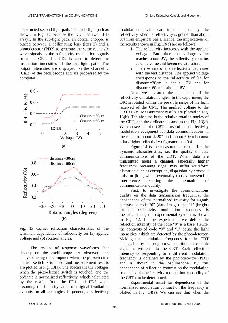
The results of response waveforms that display on the oscilloscope are observed and analysed using the computer when the piezoelectric control switch is touched, and measurement results are plotted in Fig. 13(a). The abscissa is the voltages when the piezoelectric switch is touched, and the ordinate is normalized reflectivity, which calculated by the results from the PD1 and PD2 when assuming the intensity value of original irradiation as unity for all test angles. In general, a reflectivity
modulation device can transmit data by the reflectivity when its reflectivity is greater than about 0.4 from empirical basis. Hence, the implications of the results shown in Fig. 13(a) are as follows:
1. The reflectivity increases with the applied voltage. But after the voltage value reaches about 2V, the reflectivity remains at same value and becomes saturation.
2. The rise rate of the reflectivity decreases with the test distance. The applied voltage corresponds to the reflectivity of 0.4 for distance=30cm is about 1.2V and for distance=60cm is about 1.6V.
0 1 2 3 4 5
0.2
0.4
0.6
0.8
distance=30cm distance=60cmR
efle
ctiv
ily (%
)
Voltage (V)
1.2 1.6
Next, we measured the dependence of the reflectivity on rotation angles. In the experiment, the DIC is rotated within the possible range of the light received of the CRT. The applied voltage to the CRT is 2V. Measurement results are plotted in Fig. 13(b). The abscissa is the relative rotation angles of the CRT, and the ordinate is same as the Fig. 13(a). We can see that the CRT is useful as a reflectivity modulation equipment for data communications in the range of about ±20º until about 60cm because it has higher reflectivity of greater than 0.4.
Figure 14 is the measurement results for the dynamic characteristics, i.e. the quality of data communications of the CRT. When data are transmitted along a channel, especially higher frequency, receiving signal may suffer waveform distortion such as corruption, dispersion by crosstalk noise or jitter, which eventually causes intersymbol interference resulting the attenuation of communications quality.
-30 -20 -10 0 10 20 30
0.2
0.4
0.6
0.8 distance=30cm distance=60cm
Ref
lect
ivity
(%)
Rotation angles (degrees)
First, to investigate the communications quality on the data transmission frequency, the dependence of the normalized intensity for signals contrast of code “0” (dark image) and “1” (bright) on the reflectivity modulation frequency is measured using the experimental system as shown in Fig. 12. In the experiment, we define the reflection intensity of the code “0” is a base. Hence, the contrasts of code “0” and “1” equal the light intensities, which are detected by the photodetector. Making the modulation frequency for the CRT changeable by the program when a time-series code signal is written into the CRT. Each reflection intensity corresponding to a different modulation frequency is obtained by the photodetector (PD1) and is shown in the oscilloscope. By this dependence of reflection contrast on the modulation frequency, the reflectivity modulation capability of the CRT can be determined.
Experimental result for dependence of the normalized modulation contrast on the frequency is plotted in Fig. 14(a). We can see that when the
WSEAS TRANSACTIONS on COMMUNICATIONS Xin Lin, Kazutaka Kosugi, and Hideo Itoh
ISSN: 1109-2742333
Issue 4, Volume 7, April 2008
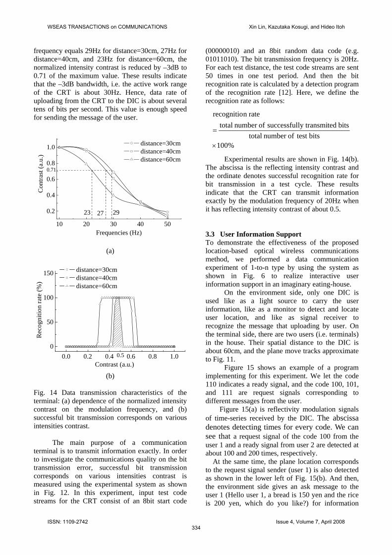
frequency equals 29Hz for distance=30cm, 27Hz for distance=40cm, and 23Hz for distance=60cm, the normalized intensity contrast is reduced by –3dB to 0.71 of the maximum value. These results indicate that the –3dB bandwidth, i.e. the active work range of the CRT is about 30Hz. Hence, data rate of uploading from the CRT to the DIC is about several tens of bits per second. This value is enough speed for sending the message of the user.
(a)
(b) Fig. 14 Data transmission characteristics of the terminal: (a) dependence of the normalized intensity contrast on the modulation frequency, and (b) successful bit transmission corresponds on various intensities contrast.
The main purpose of a communication terminal is to transmit information exactly. In order to investigate the communications quality on the bit transmission error, successful bit transmission corresponds on various intensities contrast is measured using the experimental system as shown in Fig. 12. In this experiment, input test code streams for the CRT consist of an 8bit start code
(00000010) and an 8bit random data code (e.g. 01011010). The bit transmission frequency is 20Hz. For each test distance, the test code streams are sent 50 times in one test period. And then the bit recognition rate is calculated by a detection program of the recognition rate [12]. Here, we define the recognition rate as follows:
%100bits test ofnumber total
bits tedly transmisuccessful ofnumber totalraten recognitio
×
=
10 20 30 40 50
0.2
0.4
0.6
0.8
1.0 distance=30cm distance=40cm distance=60cm Experimental results are shown in Fig. 14(b).
The abscissa is the reflecting intensity contrast and the ordinate denotes successful recognition rate for bit transmission in a test cycle. These results indicate that the CRT can transmit information exactly by the modulation frequency of 20Hz when it has reflecting intensity contrast of about 0.5. 3.3 User Information Support To demonstrate the effectiveness of the proposed location-based optical wireless communications method, we performed a data communication experiment of 1-to-n type by using the system as shown in Fig. 6 to realize interactive user information support in an imaginary eating-house.
On the environment side, only one DIC is used like as a light source to carry the user information, like as a monitor to detect and locate user location, and like as signal receiver to recognize the message that uploading by user. On the terminal side, there are two users (i.e. terminals) in the house. Their spatial distance to the DIC is about 60cm, and the plane move tracks approximate to Fig. 11.
Figure 15 shows an example of a program implementing for this experiment. We let the code 110 indicates a ready signal, and the code 100, 101, and 111 are request signals corresponding to different messages from the user.
Figure 15(a) is reflectivity modulation signals of time-series received by the DIC. The abscissa denotes detecting times for every code. We can see that a request signal of the code 100 from the user 1 and a ready signal from user 2 are detected at about 100 and 200 times, respectively.
At the same time, the plane location corresponds to the request signal sender (user 1) is also detected as shown in the lower left of Fig. 15(b). And then, the environment side gives an ask message to the user 1 (Hello user 1, a bread is 150 yen and the rice is 200 yen, which do you like?) for information
0.0 0.2 0.4 0.6 0.8 1.00
50
100
150 distance=30cm distance=40cm distance=60cm
Rec
ogni
tion
rate
(%)
Contrast (a.u.)0.5
Con
trast
(a.u
.)
Frequencies (Hz)
23 27 29
0.71
WSEAS TRANSACTIONS on COMMUNICATIONS Xin Lin, Kazutaka Kosugi, and Hideo Itoh
ISSN: 1109-2742334
Issue 4, Volume 7, April 2008

service. We also can see that the detecting time is 102 times and the request signal sender is user 1.
(a)
(b)
(c)
Fig. 15 An example for indoor information service by using the proposed system: (a) detection times of every user code, (b) giving an ask from the environment to information service, (c) uploading the answer from the user and giving a service content from the environment.
Finally, the user 1 uploads his/her selection message (Bread please) to the environment side to get a requisite information service as shown in the
lower right of Fig. 15(c). And then, the environment side gives its service contents (charges 150). The communication speed is limited at the 20Hz by the reflectivity modulation frequency of the PNLC light modulator of the CRT. Although this communication speed can be used for case of our indoor and near distance, we still want to improve it by using a PNLC light modulator, which has larger active area or a faster device. 4 Conclusion We have described a method and constructed a system for location-based information support using a CRT and a DIC. In this method, the CRT is used to upload user information and generate intensively reflectional light to extract it from background noises. The spatial optical communication characteristics of the CRT has been evaluated and also obtained several important values such as the relation between the reflectivity and applied voltage, reflectivity and rotation angles, the critical frequency of the –3dB bandwidth, and the recognition rate for bit transmission. On the other hand, the DIC with two LED arrays is employed as the medium of data transmission, and used to simultaneously detect the user location and recognize the user information. Experiments have also been performed for location detection of two users and indoor user information support.
The purpose of this study is to construct a ubiquitous information support environment and to develop a compact, low power consumption, and bidirectional communications information terminal So further study for bidirectional wireless indoor data communications via free-space beam should be conducted. Acknowledgments We are grateful to Taiheiyo Cement Corporation, for providing the piezoelectric signal generator during our experiments. References: [1] F. R. Gfeller and U. Bapst, “Wireless in-house data communication via diffuse infrared radiation,” Proc. of the IEEE 67(11), 1979, pp. 1474-1486. [2] Y. Nakata, J. Kashio, T. Kojima, and T. Noguchi, “In-house wireless communication system using infrared radiation,” Proc. Conf. on Computer Commun., 1984, pp. 333-337. [3] H. Hashemi, G. Yung, M. Kavehrad, R. Behbahani, and P. A. Galko, “Indoor propagation
detecting times
Hello user 1, A bread is ¥150 and the rice is ¥200. Which do you like ?
user 1 User location detection by DIC User ID recognition
An answer from the user
X location
Y lo
catio
n user 1
An ask for user 1 from the environment
charges
The user 1is detected
at 102 times
time-series signals from users
detecting times
request: 100 ready: 110
X location
Y lo
catio
n
user 1
charges iteration times
A question for user 1 from the environment Hello user 1, A bread is ¥150 and the rice is ¥200. Which do you like ?
User ID recognitionUser location detection by DIC
answer from the userBread please.
service content
WSEAS TRANSACTIONS on COMMUNICATIONS Xin Lin, Kazutaka Kosugi, and Hideo Itoh
ISSN: 1109-2742335
Issue 4, Volume 7, April 2008

measurements at infrared frequencies for wireless local area networks applications,” IEEE Trans. Vehic. Technol. 43, 1994, pp. 562-576. [4] J. M. Kahn and J. R. Barry, “Wireless infrared communications,” Proc. of the IEEE 85(2), 1997, pp. 265-298. [5] S. Miyamoto and N. Morinaga, “A study on performance improvement of indoor optical wireless communication system,” IEICE Tech. Rep. MWP98-5, 1998, pp. 25-32. [6] A. Ward, A. Jones, and A. Hopper, “A new location technique for the active office,” IEEE Personal Communications, 4(5) , 1997, pp. 42-47. [7] H. Nakashima and K. Hashida, “Location-based communication infrastructure for situated human support,” Proc. of the SCI2001 IV, 2001, pp. 47-51. [8] H. Itoh, T. Nishimura, Y. Yamamoto, and H. Nakashima, “Ferroelectric liquid crystal spatial light modulator for location-based communication with higher data transfer rate,” Tech. Dig. LTA2002, 2002, pp. 189. [9] T. Nishimura, H. Itoh, Y. Nakamura, Y. Yamamoto, and H. Nakashima, “A compact battery-less information terminal system for location-based interactive information support,” IPSJ 44(11), 2003, pp.2659-2669. [10] X. Lin and H. Itoh, “Video-based optical wireless communication technique,” WSEAS Trans. on Commun., 7(4), 2005, pp. 417-424. [11] X. Lin and H. Itoh, “Video-based spatial optical communications method for wearable information terminal,” Opt. Eng. 45(6), 2006, pp. 064001-1-064001-6. [12] X. Lin and H. Itoh, “Wireless personal information terminal for indoor spatial optical communication system using a modified DataSlim2,” Opt. Rev. 10(3), 2003, pp. 155-160. [13] X. Lin and H. Itoh, “Evaluation of Multi-Letters Transmission Quality of a wireless compact terminal for indoor spatial optical communications, ” Proc.(2) of 13th IST Mobile and Wireless Communications Summit 2004, pp.879-883. [14] X. Lin, K. Kosugi, and H. Itoh, “Optical Wireless Communications Method for Location-based Information Support Using a Corner-reflecting Terminal and a Distance Image Camera,” Proc. of 5th WSEAS Inter. Conf. on Electroscience 2007, pp.41-44. [15] H. Itoh, T. Nakada, S. Hiratsuka, Y. Nakamura, T. Nishimura, S. Kunifuji, H. Nakashima, and N. Iwasaki, “Indoor location and communication system for the Last-Ten-Meter information services,” Proc. of IEEE Pacific Rim Conf. On Communications, Computers, and Signal Processing 2003, 1(F38. 2), pp. 482-485.
[16] N. Koide, “Development of liquid crystal polymers,” CMC Publishing Co., Ltd., 2001. [17] H. Itoh, T. Akiyama, Y. Yano, Y. Nakamura, T. Nishimura, Y. Yamamoto, T. Hidaka, and H. Nakashima, “Lower voltage operation polymer dispersed liquid crystal modulator for the location-based information service environment,” Proc. of Contemporary Photonics Technology 2003, D-16, pp. 69-70.
WSEAS TRANSACTIONS on COMMUNICATIONS Xin Lin, Kazutaka Kosugi, and Hideo Itoh
ISSN: 1109-2742336
Issue 4, Volume 7, April 2008