Embed Size (px)
Citation preview

Cellular / Wireless LAN Repeater System by Wireless Optical Link with Optical Power Supply
NOBUO NAKAJIMA and NAOHIRO YOKOTA
Department of Human Communications The University of Electro-Communications
Chofugaoka 1-5-1, Chofu-shi, Tokyo 182-8585 JAPAN
Abstract: - Wireless market, such as cellular systems and wireless LAN, becomes huge and is still expanding. Since operational frequency and transmission bit rate are increasing, much more base stations or access points are necessary to overcome capacity and link budget problems. Most of the places suitable for the base station were already occupied by the existing systems. In the future, sometimes, new base station must be installed at the places where power supply or transmission cable is not available. The proposed repeater system is applicable for such case. The RF signals are fed to the repeater through the air by optical beams. And electrical power is fed by the optical beam, too. This paper describes the design principle and experimental results of the proposed system. For example, by using 26cm diameter optical beam for power transmission, available forward link RF power at the repeater station is 10mW in the case that the distance between the base station and the repeater station is 40 m. If a diameter of the optical beam for power transmission is 48 cm, 100 mW RF output power is available for a forward link. Since micro cell structure will become majority in the future high frequency and high bit rate cellular and wireless LAN systems, these amount of RF output power may be enough for many cases. Key-Words: - RoF, Wireless, Optical Transmission, Optical Power Transmission, Cellular System 1 Introduction A number of cellular base stations increases according to the increase of subscribers and transmission bit rates. It is getting difficult to build new base stations, especially in urban area. In some cases, the base station must be built on the place where neither transmission cable nor electrical power supply is available. The proposed system is applicable as a feed system in such a case.
Currently, a Radio on (over) fiber (RoF) technology is applied for the in-building cellular systems, in which repeater stations are equipped on every floor in order to provide cellular services wherever in the building. The advantage is that the size of the repeater stations equipped for ceilings are very compact because they are composed of only Electric to Optic (E/O) transducer, amplifier and antenna [1][2][3].
A power supply-less RoF technology was developed to enhance flexibility for installing repeater stations [4][5][6]. Electrical power is fed to the repeater station through the optical fiber in the form of optical energy. The optical fiber power transmission technology was already applied in the various applications, such as television broadcast repeater (gap filler) stations and remote video cameras [7]-[13]. In the former case, a receiver and a
transmitter are separated by the optical cables, and the receiver power is supplied by not a wire but a fiber in order to avoid the lightning shock to the system. If a metal wire were used to connect the receiver to the transmitter, the system would easily suffer lightning. Using a high power laser of which output power is 300 mW, electrical power of around 30mW is supplied to the receiver which is 6 km apart from the transmitter. In the latter case, two graded index optical fibers are used and 400mW electrical power is supplied to the camera by two 0.8 µm lasers of which output powers are 1 W, respectively. It is said that the optical power can be fed to the fiber as much as 1 W without any damage in the fiber [14][15].
Figure 1 shows the power supply-less RoF system structure [4]. The system is composed of a base station and a repeater station. Forward link RF signal modulates optical transmit power and a photo diode recovers the RF signal at the repeater station. Optical power is generated by other high power laser. The electrical power is obtained by efficient high power photo diode at the repeater station. This electrical power is fed to other components, such as an amplifier and a laser diode.
Proposed system is based on the same principle, but the optical fiber is replaced to an optical wireless transmission.
WSEAS TRANSACTIONS on COMMUNICATIONS
Nobuo Nakajima and Naohiro Yokota
ISSN: 1109-2742 882 Issue 8, Volume 7, August 2008

Fig.1 Power Supply-Less RoF System Structure
A fiber-space full optical connection
technology is applicable for the optical signal transmission through the air, taken into account [16]. Separated two fibers are connected through the air using lenses. The system has tracking capability to over come air turbulence. The proposed system uses the fiber-space full optical connection technology to transmit RF signals through the air. In addition, a power supply technology by an optical wireless transmission was newly developed. This paper describes the concept, technology and experimental results of a wireless optical feed system with optical power transmission. 2 System Configuration Figure 2 shows an image of the proposed system and Fig. 3 is a block diagram of the system. There are two stations. One is a base station and the other is a repeater station. The base station is connected to a switching station in the cellular system. The repeater station communicates with mobile terminals through the antenna. In this paper, the repeater station is supposed to be equipped on the place where both the transmission cable and the power supply do not exist.
There are three optical beams between the base station and the repeater station. Two of them carry RF signals. 1st beam is for a forward link and 2nd beam is for a reverse link. These two beams can be integrated into one beam if duplexer or half-mirror is applied. A 3rd beam transmits electrical power by optical energy. Lenses or parabolic reflectors are used so as to converge the optical beams.
As for the forward link, optical waves emitted from a LD (Laser Diode) is modulated by RF (Radio Frequency) signal which comes from TX. At the repeater station, a PD (Photo Diode) transduces optical signal to RF signal. A power amplifier is used to increase RF power to the specified output level. As for the 2nd beam, each component plays same role as
that of the 1st beam, except to employ a low noise amplifier instead of the power amplifier for amplifying received signal from mobile terminals.
Fig.2 Proposed System Image
Fig.3 Proposed System Configuration
A strong light source is necessary for a 3rd beam. A high power laser is applicable, however it has a problem about eye safety. Therefore, a conventional high power light bulb is used in the proposed system. At the repeater station, received optical energy is converted to electric power by a solar cell and the obtained electric power is used to drive the LD and amplifiers.
Table 1 shows the technical requirements for the optical components used in Fig.1.
Table 1 Technical Requirements
TXLD
PDRX
PD
LD
High PowerPD
LNA
Antenna
Fiber
Base Station Repeater Station
PA
HighPower
LD
PA : Power Amplifier, LNA : low Noise AmplifierTX : Transmitter, RX : Receiver
TXLD
PDRX
PD
LD
High PowerPD
LNA
Antenna
Fiber
Base Station Repeater Station
PA
HighPower
LD
PA : Power Amplifier, LNA : low Noise AmplifierTX : Transmitter, RX : Receiver
TX LD PD
RX PD LD
Light Solar Cell
1st
2nd
3rd
TX: Transmitter, RX: Receiver, LD: Laser Diode, PD: Photo Diode
Lens CirculatorAntenna
Base Station Repeater Station
PowerAMP
Low NoiseAMP
TX LD PD
RX PD LD
Light Solar Cell
1st
2nd
3rd
TX: Transmitter, RX: Receiver, LD: Laser Diode, PD: Photo Diode
Lens CirculatorAntenna
Base Station Repeater Station
PowerAMP
Low NoiseAMP
Radio onAir
Power byLight
Transceiver
E/OTransducer(Laser)
Lens
AmplifierAntenna
E/O TransducerSolar cell
High Power Light Source
Radio onAir
Power byLight
Transceiver
E/OTransducer(Laser)
Lens
AmplifierAntenna
E/O TransducerSolar cell
High Power Light Source
WSEAS TRANSACTIONS on COMMUNICATIONS Nobuo Nakajima and Naohiro Yokota
ISSN: 1109-2742 883 Issue 8, Volume 7, August 2008
3 RF Signal Transmission by Optical Wireless
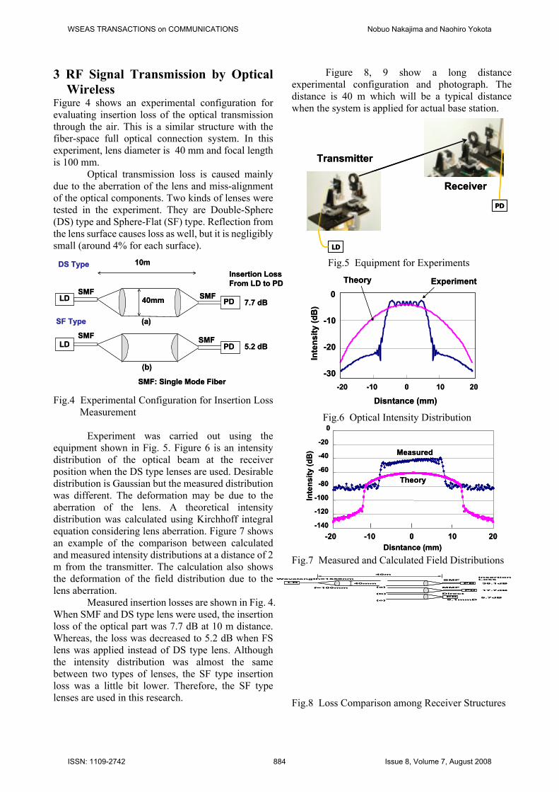
Figure 4 shows an experimental configuration for evaluating insertion loss of the optical transmission through the air. This is a similar structure with the fiber-space full optical connection system. In this experiment, lens diameter is 40 mm and focal length is 100 mm.
Optical transmission loss is caused mainly due to the aberration of the lens and miss-alignment of the optical components. Two kinds of lenses were tested in the experiment. They are Double-Sphere (DS) type and Sphere-Flat (SF) type. Reflection from the lens surface causes loss as well, but it is negligibly small (around 4% for each surface). Fig.4 Experimental Configuration for Insertion Loss
Measurement
Experiment was carried out using the equipment shown in Fig. 5. Figure 6 is an intensity distribution of the optical beam at the receiver position when the DS type lenses are used. Desirable distribution is Gaussian but the measured distribution was different. The deformation may be due to the aberration of the lens. A theoretical intensity distribution was calculated using Kirchhoff integral equation considering lens aberration. Figure 7 shows an example of the comparison between calculated and measured intensity distributions at a distance of 2 m from the transmitter. The calculation also shows the deformation of the field distribution due to the lens aberration.
Measured insertion losses are shown in Fig. 4. When SMF and DS type lens were used, the insertion loss of the optical part was 7.7 dB at 10 m distance. Whereas, the loss was decreased to 5.2 dB when FS lens was applied instead of DS type lens. Although the intensity distribution was almost the same between two types of lenses, the SF type insertion loss was a little bit lower. Therefore, the SF type lenses are used in this research.
Figure 8, 9 show a long distance experimental configuration and photograph. The distance is 40 m which will be a typical distance when the system is applied for actual base station.
Fig.5 Equipment for Experiments
Fig.6 Optical Intensity Distribution Fig.7 Measured and Calculated Field Distributions Fig.8 Loss Comparison among Receiver Structures
-20 -10 0 10 20
Disntance (mm)
0
-10
-20
-30
Inte
nsity
(dB
)
Theory Experiment
-20 -10 0 10 20
Disntance (mm)
0
-10
-20
-30
Inte
nsity
(dB
)
Theory Experiment
-140
-120
-100
-80
-60
-40
-20
0
Inte
nsity
(dB
)
-20 -10 0 10 20Disntance (mm)
Theory
Measured
-140
-120
-100
-80
-60
-40
-20
0
Inte
nsity
(dB
)
-20 -10 0 10 20Disntance (mm)
Theory
Measured
LD PD
PD
PD
SMF
MMF
Direct
(a)
(b)
(c)
40m
f=100mm
Wavelength=1550nm
40mm 38.1dB
17.7dB
5.7dB0.1mmD
InsertionLoss
LD PD
PD
PD
SMF
MMF
Direct
(a)
(b)
(c)
40m
f=100mm
Wavelength=1550nm
40mm 38.1dB
17.7dB
5.7dB0.1mmD
InsertionLoss
LD PD
LD PD40mm
(a)
SMF
(b)
SMF
10m
SMF: Single Mode Fiber
SMF SMF
SF Type
DS TypeInsertion LossFrom LD to PD
7.7 dB
5.2 dBLD PD
LD PD40mm
(a)
SMF
(b)
SMF
10m
SMF: Single Mode Fiber
SMF SMF
SF Type
DS TypeInsertion LossFrom LD to PD
7.7 dB
5.2 dB
LD
PD
Transmitter
Receiver
LD
PD
Transmitter
Receiver
WSEAS TRANSACTIONS on COMMUNICATIONS Nobuo Nakajima and Naohiro Yokota
ISSN: 1109-2742 884 Issue 8, Volume 7, August 2008

Fig.9 Experimental System
Three kinds of structure were tested to compare insertion loss performance. They are (1) SMF reception, (2) MMF (Multi Mode Fiber) reception and (3) PD direct reception. Type (1) corresponds to the fiber-space full optical connection [16]. Type (1) is the best for the flexibility. There is no restriction for the location of the transceiver. Since the lens and the receiver are connected via SMF, RF signal does not degrade during fiber transmission. But optical loss will be the highest, since the matching of the field distribution between optical beam and fiber is very critical due to the small aperture of the SMF.
Type (2) is lower RF performance because MMF can not transmit wide bandwidth. However, the loss will be smaller than (1) since MMF has larger aperture than SMF.
Type (3) is the best in terms of both loss and RF performance, but there is a limitation in the layout. PD and receiver must be equipped just after the Lens.
The measured insertion losses of these structures are shown in Fig.8. Relative performances are the same as those predicted. Huge loss of (1) may be due to the aberration of the lens and the alignment error. In the system experiments, type (3) was selected because of the lowest loss. 4 E/O Transducer Characteristics Figure 10, 11 is a measurement system of RF insertion loss between the transmitter and the receiver. Bias Tees feed driving currents for LD and PD. The impedance of the LD and PD do not same as that of RF transmission line (50 ohms). Especially, the PD is very high impedance. In order to reduce miss-matching loss between LD/PD and the 50 ohm transmission line, a 3 stub is applied. Figure 12, 13 shows the 3 stub. The impedance is matched by adjusting the length of 3 line stretchers that are
connected to the main transmission line at a quarter wavelength spacing.
Fig.10 RF Insertion Loss Measurement
Fig.11 Equipment for RF Loss Measurement
Fig.12 3 Stub Structure
Fig.13 Photograph of 3 Stub
LD PDBiasTee
BiasTee
NetworkAnalyzer
DC Bias DC Bias
3stub3stub LD PDBiasTee
BiasTee
NetworkAnalyzer
DC Bias DC Bias
3stub3stub
Line Stretcher
RFInputorOutput
LDorPD
Quarter Wavelength
Open End
Line Stretcher
RFInputorOutput
LDorPD
Quarter Wavelength
Open End
WSEAS TRANSACTIONS on COMMUNICATIONS Nobuo Nakajima and Naohiro Yokota
ISSN: 1109-2742 885 Issue 8, Volume 7, August 2008

A surface emitting laser diode is used for RF transmission (Fig.14). The feature is that the threshold power of the oscillation is extremely small comparing other kinds of laser diodes. Figure 15 shows the relationship among driving voltage, current and output power. This feature is advantageous for the repeater station because the consuming electric power must be as small as possible. Figure 16 shows the relationship between RF insertion loss and the power consumption of the surface emitting LD. 2 mW is enough drivingl power for oscillation. Figure 17 shows the frequency response of the RF insertion loss. In this case, the minimum loss between E/O and O/E transducers was 22.7 dB at 1.17 GHz. Fig.14 Surface Emitting LD (VCSEL AS-0001:
Fuji Xerox) Fig.15 Output Power vs. Supplied Voltage and
Current
Fig.16 RF Insertion Loss vs. LD Power Consumption
Fig.17 RF Insertion Loss of the Optical Parts when Surface Emitting LD is Used
Table 2 Specifications of LD and PD 5 Optical Power Transmission Table 3 shows the requirements for the optical power transmission system. In order to drive the RF power amplifier, more than several tens mW output power is required. In this research, a high power laser is not considered since eye safety is indispensable for open air usage.
Transmission loss is caused by the diffusion of the optical wave. If the large lens is used, diffusion or transmission loss becomes small. But this is disadvantage at the installation. Optical components must be as small as possible. Table 3 Technical Requirements
Figure 18, 19 shows candidates of the optical components for the power transmission. A high power LED or a tungsten halogen bulb are applicable as the optical power source. In this system, the tungsten halogen bulb is employed, because high output power is easily available. Table 4 shows major
0 1 2 3 4 5
2
1.5
1
0.5
Current (mA)
10
8
6
4
2
0
Volta
ge (V
)
Pow
er (m
W)
0 1 2 3 4 5
2
1.5
1
0.5
Current (mA)
10
8
6
4
2
0
Volta
ge (V
)
Pow
er (m
W)
LD PD
RF Loss = A / B
A B
@ 1 GHz50
40
30
200 1 2 3 4 5
Power Consumption ( mW )
Insertion Loss (dB)
LD PD
RF Loss = A / B
A B
@ 1 GHz50
40
30
200 1 2 3 4 5
Power Consumption ( mW )
Insertion Loss (dB)
22.7dB
1.1 1.2
0
90
1020304050607080
Frequency (GHz)
Inse
rtio
n Lo
ss (d
B) 22.7dB
1.1 1.2
0
90
1020304050607080
Frequency (GHz)
Inse
rtio
n Lo
ss (d
B)
3 GHzResponse0.85 A/WSensitivity
KPDE004R(KYOSEMI)
Name
PD
2 mWOutput Power
3 mAForward Current850 nmWavelengh
AS-0001(Fuji Xerox)
Name
LD
3 GHzResponse0.85 A/WSensitivity
KPDE004R(KYOSEMI)
Name
PD
2 mWOutput Power
3 mAForward Current850 nmWavelengh
AS-0001(Fuji Xerox)
Name
LD
High Available Electric Power (10mW-1W)
Eye Safety
Compactness
WSEAS TRANSACTIONS on COMMUNICATIONS Nobuo Nakajima and Naohiro Yokota
ISSN: 1109-2742 886 Issue 8, Volume 7, August 2008

specifications of the tungsten halogen bulb used in the experiments. Fig.18 Configuration of Optical Power Transmission Fig.19 Optical Components for Power Transmission Table 4 Specification of Tungsten Halogen Bulb
As for the power transmission, the lens is not suitable because it collects only small part of optical energy radiated from the bulb of which radiation is isotropic. Therefore, instead of lens, a parabolic reflector, that can collect more radiated power than the lens, is used in the proposed systems.
As for the receiver, a solar panel is used in the experimental system. Table 5 shows the specification. If the lens is applied to the receiver in order to converge the received optical power, a small solar panel can be used. The combination of lens and the small solar panel (Fig.18) is low cost alternative.
Table 5 Specification of Solar panel
The optical beam diffuses even lens or the reflector is used. The diffusion is relating to the filament structure of the bulb. Figure 20 shows a calculation model. If the filament were a point source (infinitely small), the diffusion would not happen. The size of the optical beam width h at distance L from the transmitter is approximately,
h= (L x d) / f (1) where f is focal length of the lens or parabolic reflector and d is filament length.
Supposing that Dx is the size of the solar panel, total (2 dimensional) power transmission efficiency η1 is approximated as,
ηx =Dx / h (2) In the case of 3 dimensional model,
ηxηy= Dx x Dy x f 2/ (L2 x dx x dy) (3) where ηx, ηy are the efficiencies of dimension x, y. Dx, Dy are the size of the solar panel and dx,dy are the size of the filament.
Fig.20 Calculation model (1)
Figure 21, 22 show the relationship between efficiency and system structure.
Solar Panel
Lens
Reflector
High PowerBulb
Solar Panel
Lens
Reflector
High PowerBulb
4 mm x 1.5 mmFilament Size
50 WOutput Power
12VSupply Voltage
SpecificationItem
4 mm x 1.5 mmFilament Size
50 WOutput Power
12VSupply Voltage
SpecificationItem
13.2 %Efficiency
17 VMaximum Voltage
0.59 AMaximum Current
10 WMaximum Power
240 mm x 315 mmSize
SpecificationItem
13.2 %Efficiency
17 VMaximum Voltage
0.59 AMaximum Current
10 WMaximum Power
240 mm x 315 mmSize
SpecificationItem
f
d
h=(L x d) / f
L
Dx : Width
f
d
h=(L x d) / f
L
Dx : Width
(a) Solar Panel (b) Tungsten Halogen Bulb
(c) Parabolic Mirror
(a) Solar Panel (b) Tungsten Halogen Bulb
(c) Parabolic Mirror
WSEAS TRANSACTIONS on COMMUNICATIONS Nobuo Nakajima and Naohiro Yokota
ISSN: 1109-2742 887 Issue 8, Volume 7, August 2008

Fig.21 Efficiency vs. System Structure (1)
Fig.22 Efficiency vs. System Structure (2)
Even a parabolic reflector is used (Fig.23), a part of the radiated power from the light source spills over. Collected power ratio η3 by the reflector is evaluated by the Eq. (4).
η3 = ( 1 + cos θ ) / 2 (4) where θ is a solid angle in Fig. 23.
Fig.23 Calculation Model (2)
Finally, the available power at the solar cell is evaluated by,
η1η2η3η4 x Optical sourse Power (5)
Where η4 is the conversion efficiency considering both from electrical power to optical power by the halogen bulb and from optical power to electrical power by the solar panel.
Experiment was carried out using the system configuration depicted in Fig.24. Since the dimension of the filament used in this experiment is 4mm x 1.5mm and focal length of the parabolic reflector is 2.3 cm, the beam size was 174cm x 65cm on the solar panel. Figure 25 shows a photograph of the transmitter used in the experiments.
Fig.24 Experimental System Configuration Fig.25 Tungsten Halogen Bulb with parabolic Reflector
Under the condition of experimental light source power, reflector/solar panel dimension, distance and solar panel efficiency, expected power at the receiver can be calculated by Eq.(5).
From the measured electrical power at the solar panel (102 mW), actual convesion efficiency η4 can be evaluated by,
102 (mW) = η1η2η3η4 x 50000 (mW) (6) where,
η1 = 0.15 η2 = 0.41 η3 = 0.8
1
0.1
0.01
0.001
Effic
ienc
y
η x,y
Focal Length f (m) x Solar Panel Size Dx,y (m) / Distance L (m)
d x LDx,y x f
Filament size dx,y (mm)1 2 4
10-5 10-4 10-3
ηx,y=
1
0.1
0.01
0.001
Effic
ienc
y
η x,y
Focal Length f (m) x Solar Panel Size Dx,y (m) / Distance L (m)
d x LDx,y x f
Filament size dx,y (mm)1 2 4
10-5 10-4 10-3
ηx,y=
10-5 10-4 10-3
1
0.1
0.01
0.001
Effic
ienc
y
η xη y
Focal Length f (m) x Solar Panel Size Dx=y (m) / Distance L (m)
Filament size 1.5 x 4 (mm)Sx=y=4 f
Experimental Condition
10-5 10-4 10-3
1
0.1
0.01
0.001
Effic
ienc
y
η xη y
Focal Length f (m) x Solar Panel Size Dx=y (m) / Distance L (m)
Filament size 1.5 x 4 (mm)Sx=y=4 f
Experimental Condition
Sx : Diameter
L : Distance
θ : Solid Angle Dx : Width
f : Focal Length
Sx : Diameter
L : Distance
θ : Solid Angle Dx : Width
f : Focal Length
24cm x 31.5cm
f=2.3cm
S=18cm
L=10m
Filament Size =4x1.5mm
50 W Power
24cm x 31.5cm
f=2.3cm
S=18cm
L=10m
Filament Size =4x1.5mm
50 W Power
WSEAS TRANSACTIONS on COMMUNICATIONS Nobuo Nakajima and Naohiro Yokota
ISSN: 1109-2742 888 Issue 8, Volume 7, August 2008

Thus,
η4 = 0.04 (7)
This efficiency is not so high comparing conventional solar panels ( around 0.1 to 0.2 ), but it may be reasonable considering various degradation factors, such as alignment error, tolerance of the mirror surface, tungsten halogen bulb spectrum distribution and so on.
Figure 26 shows the relationship between available electric power and the size of the parabolic reflector and the solar panel based on the experimental results. Fig.26 Size of Optical Components and Available
Electric Power 6 RF Link Budget Figure 27 shows the system structure and an example of the RF link budget for a typical configuration. The distance between the base station and the repeater station is 40 m. RF amplifiers, an antenna and a circulator are used to compose the system. Low power consumption amplifiers are developed for this system.
Fig.27 Example of the Link Budget
Photograph and the specification of the receiving amplifier is shown in Fig.28 and Table 6, respectively.
Fig.28 Low Power Consumption RF Amplifier Table 6 Specification of Receiving Amplifier
An efficient transmitting power amplifier is made of a MES FET NE76984 (NEC) as shown in Fig. 29. Driving current and bias voltage are fed by bias tees. An open stub is used for impedance matching at the input port. The power efficiency is shown in Fig. 30. Maximum efficiency is 50 % at 10 mW output power.
The link budget of the experimental system is shown in Fig. 27. In order to transmit 10 mW RF power from the antenna, 55 mW electrical power is required. When 50 W tungsten halogen bulb is used, the size of the reflector and the solar panel become around 26 cm.
If 100 mW RF output power is required and the power efficiency of the RF amplifier is assumed to be 30 %, then 390mW power is required. In this case, 48 cm diameter reflector and solar panel are necessary.
Fig.29 RF Power Amplifier (MES ET NE76084: NEC)
100 1000 10000
10
1
0.1
0.01
Ava
ilabl
e Po
wer
(W)
light Source50WFilament=4x1.5mm
Distance (m)10 20 40
Reflector Diameter (cm) x Solar Panel Size (cm square)
30 cm D40m dist.70 mW
50 cm D40 m dist.400 mW
100 1000 10000
10
1
0.1
0.01
Ava
ilabl
e Po
wer
(W)
light Source50WFilament=4x1.5mm
Distance (m)10 20 40
Reflector Diameter (cm) x Solar Panel Size (cm square)
30 cm D40m dist.70 mW
50 cm D40 m dist.400 mW
TX LD PD AMP
RX PD LD AMP
Optical Loss=5.7dB
Distance=40mRF Loss = 5.7+22.7=28.4dB
Gain 44dB( 16.3mW)
( ) : Consuming Power
SubstantialRF Gain 15.6dB
(2mW)
Gain 38.4dBRF Power 10mW(36.3mW)
RF Power0dBm
-28.4dBm
54.6mW50W
26cm
26cm x 26cm
Base Station Repeater Station
TX LD PD AMP
RX PD LD AMP
Optical Loss=5.7dB
Distance=40mRF Loss = 5.7+22.7=28.4dB
Gain 44dB( 16.3mW)
( ) : Consuming Power
SubstantialRF Gain 15.6dB
(2mW)
Gain 38.4dBRF Power 10mW(36.3mW)
RF Power0dBm
-28.4dBm
54.6mW50W
26cm
26cm x 26cm
Base Station Repeater Station
8.16 mWPower Consumption4.08 mACurrent1.8 dBNF22 dBGain
SpecificationItem
8.16 mWPower Consumption4.08 mACurrent1.8 dBNF22 dBGain
SpecificationItem
WSEAS TRANSACTIONS on COMMUNICATIONS Nobuo Nakajima and Naohiro Yokota
ISSN: 1109-2742 889 Issue 8, Volume 7, August 2008

Fig.30 RF Power Amplifier Efficiency 7 Conclusion A wireless optical feeder system with optical power transmission was investigated experimentally. This system is applicable as the feeder for the cellular base stations or the wireless LAN access points in the case that neither power supply nor transmission cable is available. In some cases, solar energy or wind energy may be applicable [17]. However, this system is more reliable because the supply power is available in any whether conditions. Furthermore, the proposed system is applicable where solar energy is not available, such in the under ground area and in the tunnel.
All of the optical and RF components applied for this system are available easily and not expensive. Although the distance of the base station and the repeater station is limited such as several tens meter, there will be many places where this system is applicable .
In order to make more compact system, efficient optical power transmission is indispensable to reduce the reflector and solar panel size. A strong optical point source, such as an arc lamp, may be suitable to meet this requirement. . References: [1] H. AIRaweshidy, et al., “Special issue on radio
over fiber systems technology and applications,” Wireless Personal Communication, vol.14, no.2, (2000)
[2] I. Harjula, A. Ramirez, F. Martinez, D. Zorrilla, M. Katz and V. Polo, “Practical Issues in the Combining of MIMO Techniques and RoF in OFDM/A Systems,” Proc. of the 7th WSEAS International Conference on ELECTRONICS, HARDWARE, WIRELESS and OPTICALCOMMUNICATIONS (EHAC’08), pp.244-248 (2008)
[3] A. Marchlewski, and H. Zimmermann, “High Speed ROF Receivers,” Proc. of the 4th WSEAS Int. Conf. on ELECTROMAGNETICS, WIRELESS and OPTICAL COMMUNICATIONS (ELECTROSCIENCE’06) , 539-551, Italy (2006)
[4] N.Nakajima, “ROF Technologies Applied for Cellular and Wireless Systems,” 2005 International Topical Meeting on Microwave Photonics, Seoul (2005)
[5] N. Nakajima, H. Mitsui, S. Osada, K. Morimoto, H. Kawano, K. Nakayama, T. Miki, K. Kawano, N.Kishi, “A Study on the Wireless Repeater without Electric Power Supply using ROF technology,” IEICE Technical Report RCS2004-411, pp/127-132 (2004)
[6] H. Kawano, N. Nakajima, “Simple and Low Loss Power-Supply-Less ROF Repeater,” AP-MWP 2006, Postdeadline Papers, p. 2, (2006)
[7] Haeiwa, Yamashita, Toba, “Recent Trends of Light Microwave Fused Technology in Broadcasting,” IEICE Magazine Vol.88, No.9, pp.735-739 (2005)
[8] http://www.icron.com/ [9] R.Pena, C.Algora, I.R. Matias, and M.
Lopez-Amo, “Fiber based 205-mW (27% efficiency) power-delivery system for an all-fiber network with optoelectronic sensor units,” Appl. Opt., vol.38, no.12, 00.2463-2466 (1999)
[10] T.Yasui, J. Ohwaki, and M. Mito, “A stable 2-W supply optical powering system,” IEEJ Transaction on Electrical and Electronic Engineering, vol.122-C, no.7, pp.1089-1093 (2002)
[11] S. Sugano, M. Nakagawa, H. Miyakawa, T. Shinoda, Y. Tanaka T. Kurokawa, T. Fukoka, and K. Ueda, “Remote sensing system based on fiber optic powering and LC optical switch”, CPT2005, p.31, Tokyo, Japan (2005)
[12] A. Yamada, N. Nagashima, S. Onuki, Y. Shimose, and T. Kikugawa, “Asymmetric-cladding 14xx-nm pump laser with high slope efficiency and fiber output power of>1 W”, Proc. Of the 2003 IEICE General Conference, C-4-13, p.299 (2003)
[13] A. L. Fahrenbrunch, A. Lopex-Otero, J.G. Werthen, and T.-C. Wu, “GaAs and InAlGaAs-based concentrator-type cell for conversion of power transmitted by optical fibers,” 25th PVSC, pp.117-120. (1996)
[14] K. Seo, N. Nishimura, and T. Shiba, “Study of High-power Endurance in Optical Fiber Links”, Proc. Of the 2003 IEICE society Confeence, B-10-2, p.321 (2003)
Gain 8dB
1 2 4 10 20
10
42
1
0.4
0.2
0.1
Consuming Power (mW)
Out
put P
ower
(mW
)
50%
Gain : 8 dBGain 8dB
1 2 4 10 20
10
42
1
0.4
0.2
0.1
Consuming Power (mW)
Out
put P
ower
(mW
)
50%
Gain : 8 dB
WSEAS TRANSACTIONS on COMMUNICATIONS Nobuo Nakajima and Naohiro Yokota
ISSN: 1109-2742 890 Issue 8, Volume 7, August 2008

[15] R. Percival, E. Sikora, and R. Wyatt, “Catastrophic damage and accelerated aging in bent fibers caused by high optical powers”, Electron. Lett., vol.36, no.5, pp.414-416 (2000)
[16] K.Kazaura, et al, “Performance Evaluation of Next Generation Free-Space Optical Communication System”, IEICE Trans. On Electronics Special Section on Evolution of Microwave and Millimeter-Wave Photonics Technology, vol.E90-C, no.2, (2007)
[17] L. Ispas, E. Franti, S. Osiceanu, and M. Stoian, “Virtual Environment for Solar Energy Systems Design and Tesitng,” Proc. of the 6th WSEAS Int. Conf. on APPLIED ELECTROMAGNETICS, WIRELESS and OPTICAL COMMUNICATIONS (ELECTROSCIENCE’08) Norway (2008)
Author’s Biographies Nobuo Nakajima, Dr. Eng. He received the B.S., M.S. and Ph.D degrees in electrical engineering from Tohoku University, Sendai, Japan, in 1970, 1972 and 1982, respectively.
In 1972 he joined the Electrical Communication Laboratory, NTT. From 1972 to 1979, he was engaged in the research on millimeter-wave circuits. From 1980 to 1985, he was working under the development of microwave and mobile radio antennas. After 1985, he was engaged in the system design of the digital cellular communication system.
In 1992, he moved to NTT DoCoMo and in 1998, he became a senior vice president. During in NTT DoCoMo, he was engaged in the development of future mobile communication systems such as IMT-2000 and 4th generation system.
In 2000, he moved to University of Electro-Communications and now he is a professor of the department of human communications and a director of Advanced Wireless Communicaton Research Center (AWCC).
He is a member of IEICE Japan, IEEE vehicular society, Japan Society of Security Management and Virtual Reality Society of Japan. Naohiro Yokota He received the B.S. and M.S. degrees in electrical engineering from The University of Electrical Communications, Tokyo, Japan, in 2006 and 2008, respectively.
In 2008, he joined E Access co. ltd.
WSEAS TRANSACTIONS on COMMUNICATIONS Nobuo Nakajima and Naohiro Yokota
ISSN: 1109-2742 891 Issue 8, Volume 7, August 2008