Embed Size (px)
Citation preview
Modern Applied Science; Vol. 6, No. 6; 2012 ISSN 1913-1844 E-ISSN 1913-1852
Published by Canadian Center of Science and Education
99
Indonesia’s Unconventional Resources, Modified Resource Triangle, and a Typical Example of Stimulation of Coalbed Methane Reservoir
S. Rachmat1, Astra A. Pramana1 & L. Febriana1 1 Petroleum Engineering Department, Bandung Institute of Technology, Bandung, Indonesia
Correspondence: Astra A. Pramana, Petroleum Engineering Department, Bandung Institute of Technology, Jl. Ganesha 10, Bandung, Indonesia. E-mail: [email protected]
Received: May 2, 2012 Accepted: May 15, 2012 Published: May 29, 2012
doi:10.5539/mas.v6n6p99 URL: http://dx.doi.org/10.5539/mas.v6n6p99
Abstract
Indonesia has been producing oil since 19th century and started producing 2 types of Unconventional Resources (UR) which are heavy oil since 1958 and Coal Bed Methane (CBM) since this year (2012). The concept of resource triangle was introduced by Masters and Gray in 1979 to describe the huge reserves of UR and its difficulty to be produced. A modified version had been done with a scale to exactly describe the amount of oil or gas reserve of UR. It is then linked with the stimulation techniques needed to produce them. To recover the heavy oil, thermal stimulation or recovery technique is needed to reduce its very high viscosity. Similarly, Coal Bed Methane (CBM) is also categorized as unconventional reservoirs (UR) because of its low permeability and can only be produced economically at commercial flow rates with special recovery processes or well-stimulation treatment. This paper will give a comparison study of producing CBM with and without hydraulic fracturing, a type of well-stimulation technology. The optimization procedure to select the type of water frac fluid and propping agent size and type that technically and economically suitable for CBM reservoir. The process was done using fracturing simulator and reservoir simulator for dual porosity system (CMG GEM). Fracturing simulator predicted the amount of fluid and propping agent and the resulting fracturing conductivity. Afterwards, the post-fracturing results will then be transferred to CMG-GEM, by which, using Warren and Root equation, the gas production profile is predicted and compared with its pre-fracturing results. From this study, optimum hydraulic fracture treatments is found by having the connected permeability around 5-10 Darcy. This can be accomplished by pumping enough volumes of proppant at low concentrations (6 ppa) into the fracture using less expensive fluids and distribute it uniformly.
Keywords: coal bed methane, stimulation, fracturing
1. Introduction
Unconventional resources are those that cannot be produced at economic flow rates without massive stimulation treatment or special recovery processes. Stimulation is a technique performed on an oil or gas well to increase production by improving the flow of hydrocarbons from the drainage area into the well bore. This technique is costly and, as a consequence, producing the UR is more expensive and brings a longer return of investment. UR are categorized as tight gas sands, oil and gas shale, heavy oil/tar sands/bitumen, coal bed methane, and gas hydrates. Fortunately, their reserves are abundant compared to that of the conventional light crude oil or gas. The current high price of oil, which is above $80, had made producing the UR is beneficial. Accordingly, the stimulation technology is getting more sophisticated and is heading to more efficient to press down its cost.
Indonesia has been producing oil since 1884 in Pangkalan Brandan by Royal Dutch Co. which merged with Shell, another operator in Kalimantan island of Indonesia, in 1907. It was an important oil producer outside of US at that time but its 2011 average production rate is only 905,000 bopd. (Anonymous, History of Shell in Indonesia, 2008). To boost its production, it is suggested to exploit the UR reservoirs, besides to have an expansive exploration. Out of the 8 types of UR, Indonesia is only producing 2 types, namely heavy oil and CBM. In 1941, Duri field of 7.1 billion STB OOIP, was discovered which commercially producing 21 oAPI heavy oil - a type of UR - since 1958. Heavy oil is characterized by its high viscosity (above 100 cP) and low API gravity (between 10 and 22o). To produce heavy oil, thermal technique is needed such that the viscosity will decrease down to a mobile range which is below 10 cP. Among the many thermal techniques are CSS (Cyclic Steam Stimulation), Steamflooding, Steam Assisted Gravity Drainage (SAGD) and In-situ Combustion. Duri is
www.ccsenet.org/mas Modern Applied Science Vol. 6, No. 6; 2012
100
the biggest steamflooding project in the world which covering 9000 ha area and had totally produced more than 1 billion bbl with the peak in 1994 of 300,000 bopd but currently is down to about 200,000 bopd (Rahman, 1997).
Methane gas produced from coal seams is called coalbed methane (CBM). Some of the atattractive advantages for CBM production are its shallow location of the reserve which reduces the cost (less than $1/Mcf) and has 3-4 times IGIP (Initial Gas In Place) storage compared to the conventional gas. However, coal mining operations in Indonesia and other countries were not patient enough to take the coal after the methane and its trapped water had been removed (Anonymous, ITB Joint Evaluation on South Sumatra CBM Area, 2007). To point it out, methane is a highly combustible gas and its release can have serious implications for the safety of mining operations. Besides, it also a potent greenhouse gas (GHG) - 23 times more harmful than carbon dioxide (CO2). Tackling methane emissions is therefore an important step in meeting the challenge of climate change and in ensuring the safety of mining operations. Methane can also act as a valuable source of energy- it is the principal constituent of natural gas - allowing countries to further diversify their energy supplies (Bauder, 2011; Abdassah, 2009).
Currently CBM accounted for 10% of natural gas resource in US. The total world reserve of CBM is predicted in the range of 5000 to 24,000 Tcf. In Indonesia, the success of 28 million m3/day low rank CBM production in Powder River Basin, Wyoming, USA, has broken the perception that Indonesian coal deposits are not prospective enough because of being too low rank (and too shallow). Located mostly in Southern Sumatra (54%), coal plays are also available in Kalimantan with type of lignite (29%), sub-bituminous (60%), and bituminous (11%). The estimated Indonesia’s CBM gas in-place is over 450 Tcf. This year is estimated to produce 2.5 mmscfd which will be converted to 6.25 MW electricity (ESDM, 2012; Stevens, 2004).
2. Modified Resource Triangle
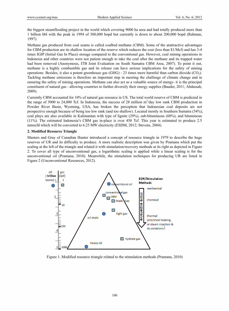
Masters and Gray of Canadian Hunter introduced a concept of resource triangle in 1979 to describe the huge reserves of UR and its difficulty to produce. A more realistic description was given by Pramana which put the scaling at the left of the triangle and related it with stimulation/recovery methods at its right as depicted in Figure 2. To cover all type of unconventional gas, a logarithmic scaling is applied while a linear scaling is for the unconventional oil (Pramana, 2010). Meanwhile, the stimulation techniques for producing UR are listed in Figure 2 (Unconventional Resources, 2012).
Figure 1. Modified resource triangle related to the stimulation methods (Pramana, 2010)

www.ccsenet.org/mas Modern Applied Science Vol. 6, No. 6; 2012
101
Figure 2. Several techniques for stimulation (Anonymous, Production Technology II Lecture Notes., 2009)
3. CBM Production Mechanisms
About 90% of the methane gas of CBM is stored in coal seams and adsorbed in the walls of micropores of 5-10Angstrom size. The remaining 10% is stored as a free gas or dissolved in the water (for a wet coal) within the macropores cleat system with more than 500A size and length up to several inches. The trapped water (or brine) that significantly affect the methane recovery, is mostly immobile bound water in the coal matrix which was by product of the coalification process. Meanwhile, the free water in the cleat system is considered as active aquifer systems (Mora, 2007; Jachen, 1994).
When the reservoir pressure is declined, the coal matrix shrinks causing the cleats to open and increases the porosity (Palmer-Mansoory Theory). If the critical pressure is passed, the methane gas from the micropore walls starts to desorb and migrates through the interconnected micropores to the cleats (diffusion). It is then gathered in the cleats together with the dissolved methane in brine and transported (convection), along with brine, to the drainage wells. The process can take years to complete which means a guaranteed methane production will be continued for quite a many years. Abundant water and small amount of gas are initially produced then exhibiting a peak gas production when the dewatering process is almost completed (Zuber, 1996).
Coals increase in rank with increasing depth because rank is influenced by temperature, pressure and length of burial. Cleat frequency (number of cleat per meter) is highest in low-volatile bitumen rank coals. The orientation and magnitude of stress fields can strongly influence CBM recovery. Horizontal stress perpendicular to the face cleat can close the face cleat openings and cause low permeability. If minimum vertical stress is greater than the horizontal stress, then less effective horizontal fractures will likely be propagated. The effectiveness of induced fractures designed to propagate vertically through several coal seams will also depend on the stress conditions of the intervening strata. Beds that are barriers to the vertical propagation of fractures will cause an ineffective treatment
To increase methane gas production at CBM play, there are 2 common methods which are (Fekete, 2010; Holdicth, 1993; Olsen, 2003; Leschyshyn, 2005):
• Stimulation techniques to increase the permeability such as fracturing, cavitization, under reaming, and Surface-in-seam (SIS);
• Enhance recovery technique of CBM (ECBM) such as CO2 - or N2 -injection or both which have more affinity to coal than the methane. Injecting these gases will make coal adsorbing them and displaces the methane. Moreover, the new additional technique for methanogenesis by injecting the microbes for producing the methane gas to the unproductive ECBM wells is currently under research. This cycle will ensure the methane supply from the coalbed for years.
Stimulation has been done for many of the CBM wells and therefore is the focus of this paper while enhanced recovery is still under pilot test such as in Allison unit at the northern San Juan Basin, New Mexico, USA. A 70% CO2 content predicted in Natuna gas giant reservoir was cited to undergo enhance recovery process for
www.ccsenet.org/mas Modern Applied Science Vol. 6, No. 6; 2012
102
CBM plays in Kalimantan, Indonesia. Up to now, the Natuna gas project has not been producing yet (ESDM, 2012).
4. Theory
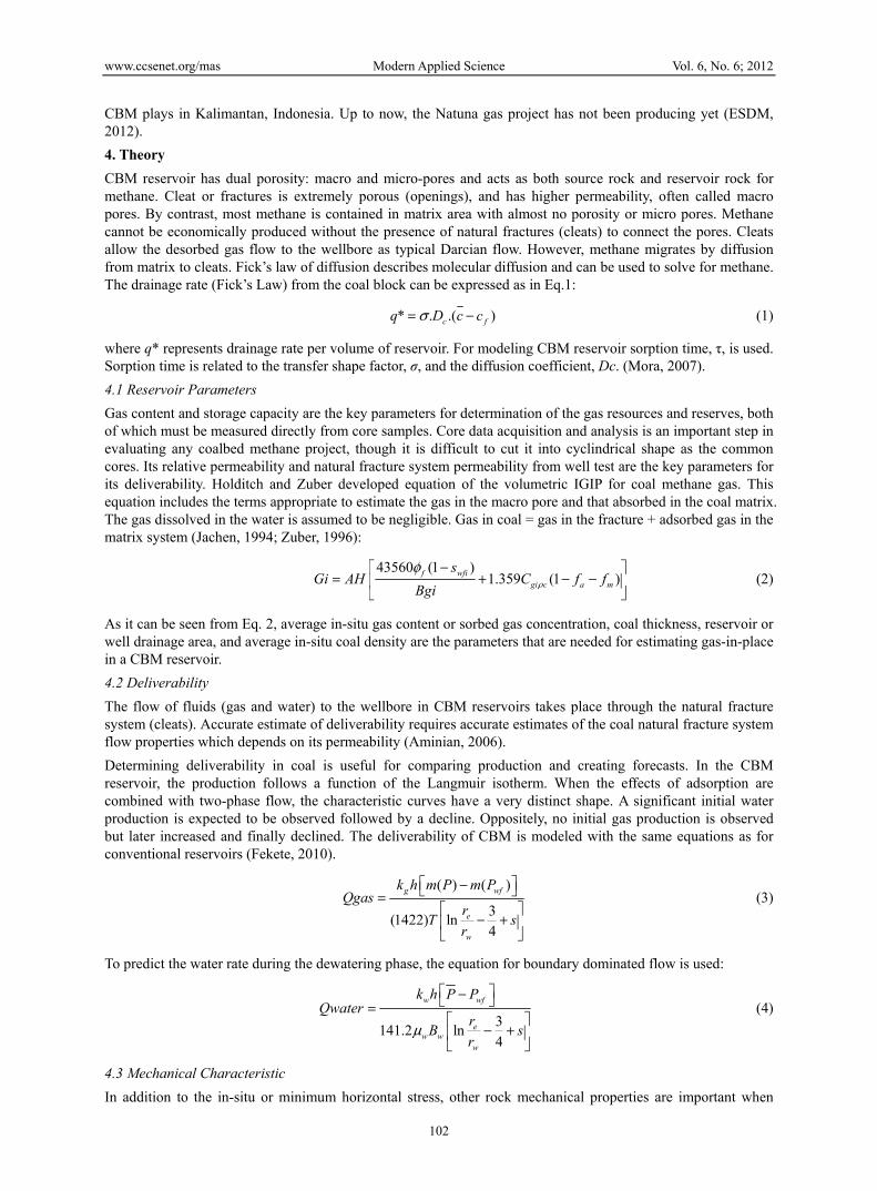
CBM reservoir has dual porosity: macro and micro-pores and acts as both source rock and reservoir rock for methane. Cleat or fractures is extremely porous (openings), and has higher permeability, often called macro pores. By contrast, most methane is contained in matrix area with almost no porosity or micro pores. Methane cannot be economically produced without the presence of natural fractures (cleats) to connect the pores. Cleats allow the desorbed gas flow to the wellbore as typical Darcian flow. However, methane migrates by diffusion from matrix to cleats. Fick’s law of diffusion describes molecular diffusion and can be used to solve for methane. The drainage rate (Fick’s Law) from the coal block can be expressed as in Eq.1:
* . .( ) c fq D c c (1)
where q* represents drainage rate per volume of reservoir. For modeling CBM reservoir sorption time, τ, is used. Sorption time is related to the transfer shape factor, σ, and the diffusion coefficient, Dc. (Mora, 2007).
4.1 Reservoir Parameters
Gas content and storage capacity are the key parameters for determination of the gas resources and reserves, both of which must be measured directly from core samples. Core data acquisition and analysis is an important step in evaluating any coalbed methane project, though it is difficult to cut it into cyclindrical shape as the common cores. Its relative permeability and natural fracture system permeability from well test are the key parameters for its deliverability. Holditch and Zuber developed equation of the volumetric IGIP for coal methane gas. This equation includes the terms appropriate to estimate the gas in the macro pore and that absorbed in the coal matrix. The gas dissolved in the water is assumed to be negligible. Gas in coal = gas in the fracture + adsorbed gas in the matrix system (Jachen, 1994; Zuber, 1996):
43560 (1 )1.359 (1 )
f wfigi c a m
sGi AH C f f
Bgi
(2)
As it can be seen from Eq. 2, average in-situ gas content or sorbed gas concentration, coal thickness, reservoir or well drainage area, and average in-situ coal density are the parameters that are needed for estimating gas-in-place in a CBM reservoir.
4.2 Deliverability
The flow of fluids (gas and water) to the wellbore in CBM reservoirs takes place through the natural fracture system (cleats). Accurate estimate of deliverability requires accurate estimates of the coal natural fracture system flow properties which depends on its permeability (Aminian, 2006).
Determining deliverability in coal is useful for comparing production and creating forecasts. In the CBM reservoir, the production follows a function of the Langmuir isotherm. When the effects of adsorption are combined with two-phase flow, the characteristic curves have a very distinct shape. A significant initial water production is expected to be observed followed by a decline. Oppositely, no initial gas production is observed but later increased and finally declined. The deliverability of CBM is modeled with the same equations as for conventional reservoirs (Fekete, 2010).
( ) ( )
3(1422) ln
4
g wf
e
w
k h m P m PQgas
rT s
r
(3)
To predict the water rate during the dewatering phase, the equation for boundary dominated flow is used:
3141.2 ln
4
w wf
ew w
w
k h P PQwater
rB s
r
(4)
4.3 Mechanical Characteristic
In addition to the in-situ or minimum horizontal stress, other rock mechanical properties are important when
www.ccsenet.org/mas Modern Applied Science Vol. 6, No. 6; 2012
103
designing a hydraulic fracture. Poisson’s ratio is defined as “the ratio of lateral expansion to longitudinal contraction for a rock under a uniaxial stress condition”. Values of Poisson’s ratio can be computed with high-frequency sonic log measurements. The values of Poisson’s ratio are important in calculating the in-situ stress distribution in a layered reservoir system. There can be differences between dynamically measured values of Poisson’s ratio and those measured in static tests in the laboratory.
y
x
V
(5)
Minus sign (-) to keep the value Poisson’s ratio still positive. Poisson's ratio number has range between 0.2-0.35. The value of Poisson’s ratio is used in Eq. 6 to convert the effective vertical stress component into an effective horizontal stress component. The effective stress is defined as the total stress minus the pore pressure (Holdicth, 1993; USDE, 2004):
min ( ) ob p p ext
v
1 v (6)
Young’s modulus is defined as “the ratio of stress to strain for uniaxial stress” (Gidley, 1989). The modulus of a material is a measure of the stiffness of the material. If the modulus is large, the material is stiff. In hydraulic fracturing, a stiff rock will result in more narrow fractures. If the modulus is low, the fractures will be wider. The modulus of a rock will be a function of the lithology, porosity, fluid type, and other variables. Because coal is highly cleated, the modulus of the coal seam in-situ may be very low. In very low modulus, highly cleated coal seams, it is likely that most fractures will be widened and short, that is, not penetrating far into the formation from the well bore.
4.4 Hydraulic Fracturing
Hydraulic fracturing is the process of pumping a fluid into a wellbore at an injection rate that is too high for the formation to accept in a radial flow pattern. As the resistance to flow in the formation increases, the pressure in the wellbore increases to a value that exceeds the breakdown pressure of the formation that is open to the wellbore. Once the formation “breaks-down”, a crack or fracture is formed, and the injected fluid begins moving down the fracture. In most formations, a single, vertical fracture is created that propagates in two directions from the wellbore. These fracture “wings” are 180 degree apart, and are normally assumed to be identical in shape and size at any point in time. In naturally fractured or cleated formations, such as gas shale or coal seams, it is possible that multiple fractures can be created and propagated during a hydraulic fracture treatment.
The reason that the deeply or shallowly buried pressure seal coal seams cannot be effectively developed is low permeability. Thus, hydraulic fracturing can be become an important stimulation technology in the coal seams. This method promotes a rapid development of the coal bed methane industry recently, and makes many advantages in basic research, evaluation technique and production technology. Moreover, although a lot of efforts have made and a great achievement has gained in evaluation and exploitation of cabled methane resource in the world, there exist a lot of unresolved technical difficulties; one of them is design and technology of hydraulic fracturing in a low permeability coal-bed reservoir. Viewing the current situation of hydraulic fracturing in coal seam, there exists the common characteristic of low production rate and fast decline, it is resulted from many factors, and the most important factors include (Zhou, 1993):
• Shorter fracture length;
• Serious damage of fracturing fluid to formation;
• Low fracturing fluid efficiency.
4.5 Properties of a Fracturing Fluid
The ideal fracturing fluid should be compatible with the formation rock, generate enough pressure drops down the fracture to create a wide fracture, be able to transport the propping agent in the fracture, break back to a low viscosity fluid for clean up after the treatment, and be cost effective. The family of fracture fluids available consists of water base fluids, oil base fluids, acid base fluids and foam fluids. The water based fluid is common used to fracture treat coal seam reservoirs. The viscosity of the fracture fluid is important. The fluid should be viscous enough (normally 50-1000 cp) to create a wide fracture (normally 0.2-1.0 in) and transport the propping agent into the fracture (normally 10s to 100s of feet). The density of the fluid is also important. Water based fluids have densities near 8.4 ppg. These are the kind of water based fluid from database of the fracturing simulator:
1) ClearFrac (JW) fluids
www.ccsenet.org/mas Modern Applied Science Vol. 6, No. 6; 2012
104
ClearFrac fluid is a viscous elastic surfactant (VES), not a long-chain polymer that can leave residue in the gravel pack or fracture proppant pack. The fluid is compatible with most common brines including KCl. Temperature limit of the fluid depends on the brine type and density, but is typically 200 degF for densities lower than 8.6 lbm/gal [3.9 kgm/L] and 150 to 175°F [65 to 79°C] for higher densities (Ledy, 2011).
These surfactants is less damage to the proppant pack and fracture face. VES fluids are not as sensitive to shear history as polymer-base fluids. VES fluids is sensitive to temperature, therefore the surfactant concentration (and in some cases, the salt concentration) must be adjusted accordingly (Gulbis, 2006).
2) Waterfrac (WF) fluid
Waterfrac fluid uses linear (uncross linked) gels of fresh water, seawater or potassium chloride brines as efficient and economical fracturing fluids. Guar and hydroxy-propylguar (HPG) gelling agents are the most common polymers used to prepare Waterfrac fluids. A cellulose-derivative gelling agent and xanthan gum are also available. Waterfrac fluids are identified by the letters WF* followed by three digits to indicate the type and concentration of gelling agent. The first digit indicates the type of gelling agent: “1” for guar and “2” for HPG. The last two digits indicate the concentration of thickener in lbm/1000 gal [kgm/3785 L] of fluid. Example: WF 140 contains a guar gelling agent at a concentration of 40 lbm/1000 gal [18 kgm/3785 L] (Ledy, 2011).
3) Widefrac (YF) fluids
The Widefrac fluid system utilizes the very viscous solution formed by cross linking Waterfrac fluids. Cross linking agents are used to dramatically increase the effective molecular weight of the polymer, thereby increasing the viscosity of the solution. The temperature range is from 175 to 350°F [79 to 177°C with additional borate compounds (Deuel & Neukorn, 1949) and transition metal complexes (Chrisp, 1967) which react with guar and HPG through cis-OH pairs on the galactose side chains to form a complex structure molecule. The borate ion is used to produce very viscous gels with guar and HPG that can be stable above 300°F (Ledy, 2011; Gulbis, 2006).
Types of Propping Agents
Generally, sand is used to prop open fractures in shallow formations. For coal seam reservoirs, sand is usually the best choice for a propping agent and virtually every fracture treatment in a coal seam reservoir uses sand. Sand is much less expensive per pound than the resin-coated sand or the ceramic proppants. Resin-coated (epoxy) sand is stronger than sand and is used where more compressive strength is required to minimize proppant crushing. Some resins can be used to form a consolidated sand pack in the fracture, which will help to eliminate proppant flow back into the wellbore. Resin coated sand is more expensive than sand. Ceramic proppants consist of sintered bauxite, intermediate strength proppant (ISP), and light weight proppant (LWP). The strength of the proppant is proportional to its density. Also, the higher strength proppants, like sintered bauxite, cost more than ISP and LWP. Ceramic proppants are used to stimulate deep (>8,000 ft) wells where large values of in-situ stresses will apply large forces on the propping agent. For shallow wells, where the effective stress is less than 4000 psi, sand can be used to create high conductivity fractures. As the effective stress increases to larger and larger values, then the higher strength, more expensive propping agents must be used to create a high conductivity fracture.
4.6 Economy Study
The following are the procedure taken for economic to select the best stimulation parameters economically (Abdassah, 2009):
1) Collect data result from fracturing simulator e.g. total volume pad (Gallons unit), and Proppant mass (lbm)
2) Calculate total treatment cost by count up the fluid cost, proppant cost, power cost, and fixed cost.
3) Obtaining gas rate production yearly (mscfd) within 10-20 years of production time from CMG GEM simulation.
4) Calculate yearly revenue (in US dollar) by multiplying gas price ($/mscf) with cumulated gas production yearly (mscf/year). Gas Price was assumed constant at $6/mscf.
5) Calculate Net Present Value, Pay Out Time and Rate of Return for each case by assuming constant value of MARR 15%.
6) Selecting fracturing fluid and propping agent which gives the highest NPV and IRR > MARR.
4.7 Description of Modeling Studies
A synthetic model is defined in order to simulate conditions obtained in CBM wells before and after fracturing
www.ccsenet.org/mas Modern Applied Science Vol. 6, No. 6; 2012
105
treatments. The initial CBM in-place before fracturing was calculated by computerized program using CMG GEM simulator and validate it with deterministic equation by Holditch & Zuber. Thus, the synthetic model gives an accurate result of recovery factor before and after fracturing treatments.
Reservoir data gained from literature review is used for fracturing simulator in fracturing fluid and propping agent process selections. Specific characteristic of coal rank with type High volatile bituminous was used in it. The optimum fracturing fluid and propping agent was selected technically reach the design length of 100 ft and economically give the highest net present value (NPV) and IRR > MARR. Afterwards, the simulation will be run for two different coal ranks, which are sub-bituminous and anthracite. The properties data was hypothetically gained from Handbook of Coal Analysis. Every coal rank has different properties, with its different mechanical, physical, reservoir properties, these coal ranks will definitely give different fracture geometry model, and hence it will affect to gas and water production profile. Finally, the conclusion is expected to cope with what is specific type of frac fluid and prop agent to be used for cbm wells and what coal ranks will give the most economically to do the fracturing treatments. The recommendation will then be derived as what is best condition for them to do hydraulic fracturing.
4.8 Hydraulic Fracturing Modeling
In the hydraulic fracturing simulation, the well completion was designed relatively simple using open-hole single-seam under reamed. Tubing Size is 2 3/8”, Casing 7”, Hole size 9 7/8”. The simulation runs were made by changing the fracturing fluid for selecting optimum fluid. Furthermore, it runs by changing the propping agent for selecting optimum prop agent type and size. The reservoir data used is described in the Table 1. For the two cases sub bituminous and anthracite were run by using the selected fracturing fluid and propping agent to get the fracture geometry and fracture conductivity from both coal ranks.
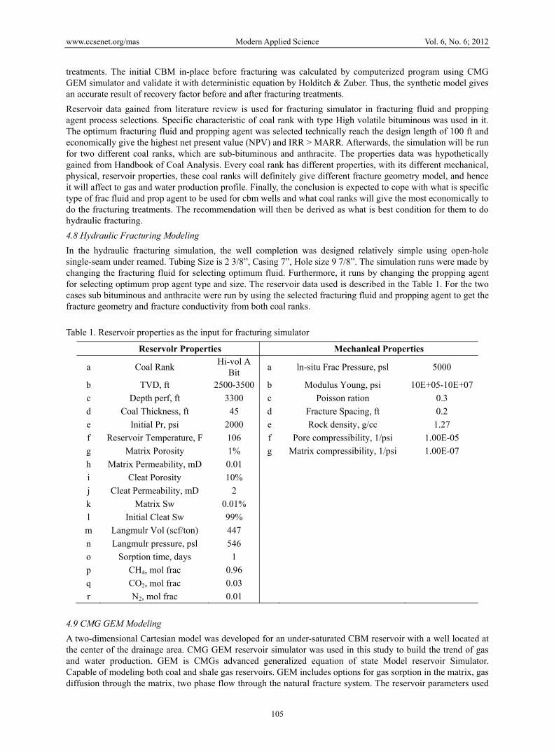
Table 1. Reservoir properties as the input for fracturing simulator
Reservolr Properties Mechanlcal Properties
a Coal Rank Hi-vol A
Bit a ln-situ Frac Pressure, psl 5000
b TVD, ft 2500-3500 b Modulus Young, psi 10E+05-10E+07
c Depth perf, ft 3300 c Poisson ration 0.3
d Coal Thickness, ft 45 d Fracture Spacing, ft 0.2
e Initial Pr, psi 2000 e Rock density, g/cc 1.27
f Reservoir Temperature, F 106 f Pore compressibility, 1/psi 1.00E-05
g Matrix Porosity 1% g Matrix compressibility, 1/psi 1.00E-07
h Matrix Permeability, mD 0.01
i Cleat Porosity 10%
j Cleat Permeability, mD 2
k Matrix Sw 0.01%
l Initial Cleat Sw 99%
m Langmulr Vol (scf/ton) 447
n Langmulr pressure, psl 546
o Sorption time, days 1
p CH4, mol frac 0.96
q CO2, mol frac 0.03
r N2, mol frac 0.01
4.9 CMG GEM Modeling
A two-dimensional Cartesian model was developed for an under-saturated CBM reservoir with a well located at the center of the drainage area. CMG GEM reservoir simulator was used in this study to build the trend of gas and water production. GEM is CMGs advanced generalized equation of state Model reservoir Simulator. Capable of modeling both coal and shale gas reservoirs. GEM includes options for gas sorption in the matrix, gas diffusion through the matrix, two phase flow through the natural fracture system. The reservoir parameters used
www.ccsenet.org/mas Modern Applied Science Vol. 6, No. 6; 2012
106
are summarized in Table 1. The simulation runs were made by changing the cleat or fracture permeability in the treatment area and also the porosity changing due to the presence of propping agent after stimulation.
5. Results and Analysis
5.1 CMG GEM Results before Fracturing Treatment
Numerical simulation is used to estimate volume bulk reservoir, IGIP and total water production. CMG GEM is a simulator that capable to model a behavior of dual porosity reservoir, it includes options for gas sorption in the matrix and gas diffusion through the matrix. In order to use this simulation, a two dimensional Cartesian was developed for an under-saturated CBM reservoir with a well located at the centre of drainage area. The flowing bottomhole pressure was kept at 100 psia and the reservoir parameters used to develop the base model are summarized in Table 2. OGIP from simulation result was 1.0905E+08 scf, it is slightly different from IGIP volumetric calculation result that was 1.094E+08 scf. This reserves estimation will be used later in production enhancement and stimulation. The total cumulative water production for 20 years is estimates to be around 268215 bbl and for the cumulative gas production is about 9.36 x 10⁷ scf.
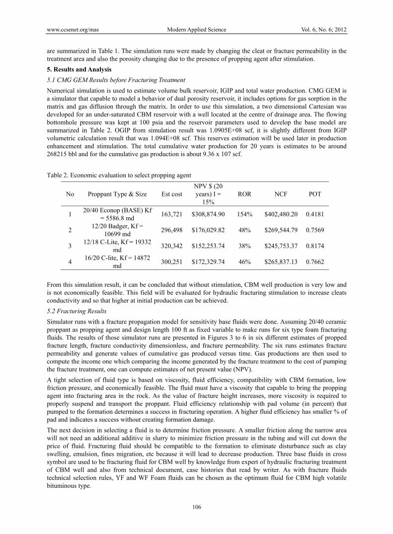
Table 2. Economic evaluation to select propping agent
No Proppant Type & Size Est cost NPV $ (20 years) I =
15% ROR NCF POT
1 20/40 Econop (BASE) Kf
= 5586.8 md 163,721 $308,874.90 154% $402,480.20 0.4181
2 12/20 Badger, Kf =
10699 md 296,498 $176,029.82 48% $269,544.79 0.7569
3 12/18 C-Lite, Kf = 19332
md 320,342 $152,253.74 38% $245,753.37 0.8174
4 16/20 C-lite, Kf = 14872
md 300,251 $172,329.74 46% $265,837.13 0.7662
From this simulation result, it can be concluded that without stimulation, CBM well production is very low and is not economically feasible. This field will be evaluated for hydraulic fracturing stimulation to increase cleats conductivity and so that higher at initial production can be achieved.
5.2 Fracturing Results
Simulator runs with a fracture propagation model for sensitivity base fluids were done. Assuming 20/40 ceramic proppant as propping agent and design length 100 ft as fixed variable to make runs for six type foam fracturing fluids. The results of those simulator runs are presented in Figures 3 to 6 in six different estimates of propped fracture length, fracture conductivity dimensionless, and fracture permeability. The six runs estimates fracture permeability and generate values of cumulative gas produced versus time. Gas productions are then used to compute the income one which comparing the income generated by the fracture treatment to the cost of pumping the fracture treatment, one can compute estimates of net present value (NPV).
A tight selection of fluid type is based on viscosity, fluid efficiency, compatibility with CBM formation, low friction pressure, and economically feasible. The fluid must have a viscosity that capable to bring the propping agent into fracturing area in the rock. As the value of fracture height increases, more viscosity is required to properly suspend and transport the proppant. Fluid efficiency relationship with pad volume (in percent) that pumped to the formation determines a success in fracturing operation. A higher fluid efficiency has smaller % of pad and indicates a success without creating formation damage.
The next decision in selecting a fluid is to determine friction pressure. A smaller friction along the narrow area will not need an additional additive in slurry to minimize friction pressure in the tubing and will cut down the price of fluid. Fracturing fluid should be compatible to the formation to eliminate disturbance such as clay swelling, emulsion, fines migration, etc because it will lead to decrease production. Three base fluids in cross symbol are used to be fracturing fluid for CBM well by knowledge from expert of hydraulic fracturing treatment of CBM well and also from technical document, case histories that read by writer. As with fracture fluids technical selection rules, YF and WF Foam fluids can be chosen as the optimum fluid for CBM high volatile bituminous type.

www.ccsenet.org/mas Modern Applied Science Vol. 6, No. 6; 2012
107
From selecting propping agent, the simulation presents the effect of size proppant with the fracture propagation model. Six different size from smaller (20/40) to bigger (16/20) needs more concentration proppant to reach design length 100 ft. In theory, the more proppant pumped the greater the area fract formed which will increase the propped width and FCD. Furthermore, FCD and conductivity are the fracture geometry parameter that used for analyze estimate production and the success of a fracturing operation. A factor that must be viewed from a proppant agent is a force against the pressure that will be received after the closing area fracture or closure pressure. Each type of proppant has a separate range for each pressure that can be accepted.
In contrast, ceramic type with size 16/20, the biggest one, only need 8 ppa to reach the design length. Consequently, it will give a less cost compared to 12/18 carbo lite.
Figure 3. Cumulative sub-bituminous CBM production before (left) and after (right) fracturing
Figure 4. Gas rate sub-bituminous CBM gas rate before (left) and after (right) fracturing
Figure 5. Cumulative anthracite CBM production before (left) and after (right) fracturing
www.ccsenet.org/mas Modern Applied Science Vol. 6, No. 6; 2012
108
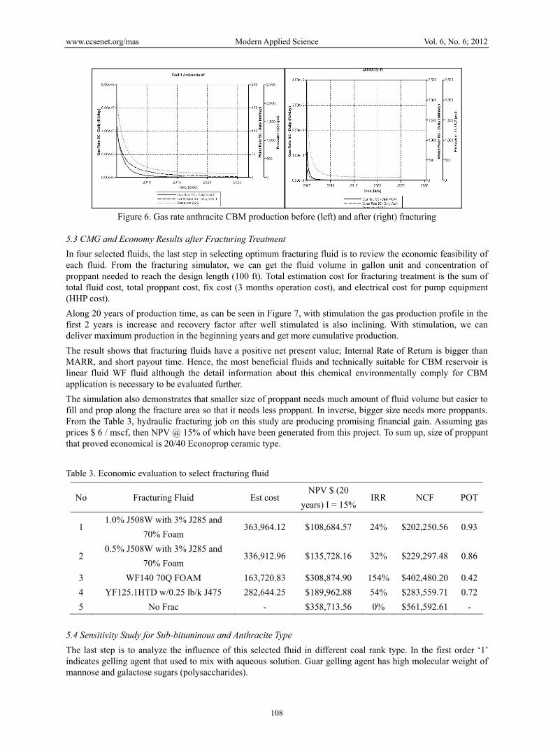
Figure 6. Gas rate anthracite CBM production before (left) and after (right) fracturing
5.3 CMG and Economy Results after Fracturing Treatment
In four selected fluids, the last step in selecting optimum fracturing fluid is to review the economic feasibility of each fluid. From the fracturing simulator, we can get the fluid volume in gallon unit and concentration of proppant needed to reach the design length (100 ft). Total estimation cost for fracturing treatment is the sum of total fluid cost, total proppant cost, fix cost (3 months operation cost), and electrical cost for pump equipment (HHP cost).
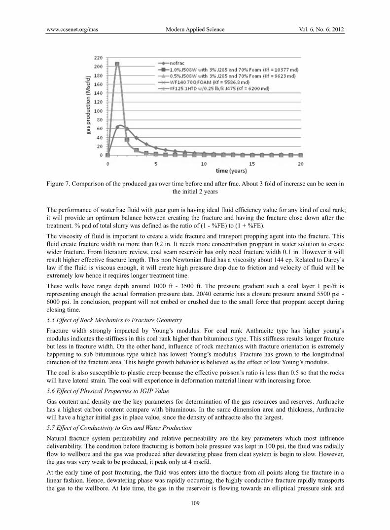
Along 20 years of production time, as can be seen in Figure 7, with stimulation the gas production profile in the first 2 years is increase and recovery factor after well stimulated is also inclining. With stimulation, we can deliver maximum production in the beginning years and get more cumulative production.
The result shows that fracturing fluids have a positive net present value; Internal Rate of Return is bigger than MARR, and short payout time. Hence, the most beneficial fluids and technically suitable for CBM reservoir is linear fluid WF fluid although the detail information about this chemical environmentally comply for CBM application is necessary to be evaluated further.
The simulation also demonstrates that smaller size of proppant needs much amount of fluid volume but easier to fill and prop along the fracture area so that it needs less proppant. In inverse, bigger size needs more proppants. From the Table 3, hydraulic fracturing job on this study are producing promising financial gain. Assuming gas prices $ 6 / mscf, then NPV @ 15% of which have been generated from this project. To sum up, size of proppant that proved economical is 20/40 Econoprop ceramic type.
Table 3. Economic evaluation to select fracturing fluid
No Fracturing Fluid Est cost NPV $ (20
years) I = 15%IRR NCF POT
1 1.0% J508W with 3% J285 and
70% Foam 363,964.12 $108,684.57 24% $202,250.56 0.93
2 0.5% J508W with 3% J285 and
70% Foam 336,912.96 $135,728.16 32% $229,297.48 0.86
3 WF140 70Q FOAM 163,720.83 $308,874.90 154% $402,480.20 0.42
4 YF125.1HTD w/0.25 lb/k J475 282,644.25 $189,962.88 54% $283,559.71 0.72
5 No Frac - $358,713.56 0% $561,592.61 -
5.4 Sensitivity Study for Sub-bituminous and Anthracite Type
The last step is to analyze the influence of this selected fluid in different coal rank type. In the first order ‘1’ indicates gelling agent that used to mix with aqueous solution. Guar gelling agent has high molecular weight of mannose and galactose sugars (polysaccharides).
www.ccsenet.org/mas Modern Applied Science Vol. 6, No. 6; 2012
109
Figure 7. Comparison of the produced gas over time before and after frac. About 3 fold of increase can be seen in
the initial 2 years
The performance of waterfrac fluid with guar gum is having ideal fluid efficiency value for any kind of coal rank; it will provide an optimum balance between creating the fracture and having the fracture close down after the treatment. % pad of total slurry was defined as the ratio of (1 - %FE) to (1 + %FE).
The viscosity of fluid is important to create a wide fracture and transport propping agent into the fracture. This fluid create fracture width no more than 0.2 in. It needs more concentration proppant in water solution to create wider fracture. From literature review, coal seam reservoir has only need fracture width 0.1 in. However it will result higher effective fracture length. This non Newtonian fluid has a viscosity about 144 cp. Related to Darcy’s law if the fluid is viscous enough, it will create high pressure drop due to friction and velocity of fluid will be extremely low hence it requires longer treatment time.
These wells have range depth around 1000 ft - 3500 ft. The pressure gradient such a coal layer 1 psi/ft is representing enough the actual formation pressure data. 20/40 ceramic has a closure pressure around 5500 psi - 6000 psi. In conclusion, proppant will not embed or crushed due to the small force that proppant accept during closing time.
5.5 Effect of Rock Mechanics to Fracture Geometry
Fracture width strongly impacted by Young’s modulus. For coal rank Anthracite type has higher young’s modulus indicates the stiffness in this coal rank higher than bituminous type. This stiffness results longer fracture but less in fracture width. On the other hand, influence of rock mechanics with fracture orientation is extremely happening to sub bituminous type which has lowest Young’s modulus. Fracture has grown to the longitudinal direction of the fracture area. This height growth behavior is believed as the effect of low Young’s modulus.
The coal is also susceptible to plastic creep because the effective poisson’s ratio is less than 0.5 so that the rocks will have lateral strain. The coal will experience in deformation material linear with increasing force.
5.6 Effect of Physical Properties to IGIP Value
Gas content and density are the key parameters for determination of the gas resources and reserves. Anthracite has a highest carbon content compare with bituminous. In the same dimension area and thickness, Anthracite will have a higher initial gas in place value, since the density of anthracite also the largest.
5.7 Effect of Conductivity to Gas and Water Production
Natural fracture system permeability and relative permeability are the key parameters which most influence deliverability. The condition before fracturing is bottom hole pressure was kept in 100 psi, the fluid was radially flow to wellbore and the gas was produced after dewatering phase from cleat system is begin to slow. However, the gas was very weak to be produced, it peak only at 4 mscfd.
At the early time of post fracturing, the fluid was enters into the fracture from all points along the fracture in a linear fashion. Hence, dewatering phase was rapidly occurring, the highly conductive fracture rapidly transports the gas to the wellbore. At late time, the gas in the reservoir is flowing towards an elliptical pressure sink and
www.ccsenet.org/mas Modern Applied Science Vol. 6, No. 6; 2012
110
most of the gas enters near the tip of the fracture.
From this study, hydraulic fracture treatments for CBM wells would suggest that successful stimulation of unconventional gas reservoir like cbm is not necessary creating a long, conductive fracture to build a debottlenecking in surrounding the wellbore area. Successful stimulation is enough by opening the connected permeability around 5-10 Darcy. It will be accomplished by pumping enough volumes of proppant at low concentrations (6 ppa) into the fracture using less expensive fluids and uniformly distribute small and economically proppant into the fracture area.
5.8 Economy Analysis for Three Type Coal
Fracturing treatment cost is determined by summing the fluid cost per gallon of volume fluid needed to crack the formation as per design length, proppant volume needed per fracture area, electricity cost for pump, and associated fixed cost. The price of proppant used depends on the fracture conductivity. Sub Bituminous type needed higher concentration of proppant to create 100 ft of design length. So that it will need more expensive in total fluid cost. Since this well has a drainage area of 20 acre it was not economically for sub bituminous to do a fracturing treatment but it can be economically if the drainage area is bigger than what assumed.
On the other hand, fracturing treatment is essential for economic coalbed gas production of high volatile bituminous and anthracite coal rank type, it results a positive Net Present Value and IRR that is higher than MARR. Fracturing treatment is even can increase the recovery factor of gas produced into 97% for Anthracite type.
6. Conclusion
Indonesia has been producing heavy oil and CBM, two types of UR. Without stimulation techniques, these UR could not be produced at high commercial rates. A typical example of hydraulic fracturing of CBM reservoirs could boost the production peak about 300%. Optimum fluid type for CBM fracturing is water base fluid with 40 lbm/gal guar gelling agent resulting in high fluid efficiency and less fluid loss. In the other side, ceramic type propping agent with size 20/40 is found to be optimum. Simulation study on the 3-D models of the hydraulic fracturing process found a wider and shorter effective half-length of fractures for this well but with a very high conductivity in wellbore area of 100 ft. Hence, it can greatly enlarge the percentage of IGIP that can be produced. It is also found that anthracite coal type is more stiff and has higher fracture conductivity than sub bituminous and therefore lengthen the fracture compared to sub- bituminous.with bigger fracture permeability. A successful stimulation for CBM wells is enough by opening the connected permeability to be around 5-10 Darcy. It is then accomplished by pumping enough volumes of proppant at low concentrations (6 ppa) into the fracture using less expensive fluids and uniformly distribute small and economical proppant into the fracturing area.
References
Abdassah, D. (2009). Coalbed Methane, A Lecture Note. Bandung: ITB.
Aminian, K. (2006). Evaluation of Coalbed Methane Reservoirs. Petroleum and Natural Gas Engineering Dept, West Virginia University.
Anonymous. (2008). History of Shell in Indonesia. Retrieved in 2012 from http://shell.co.id/home/content/idn/aboutshell
Anonymous. (2007). ITB Joint Evaluation on South Sumatra CBM Area. Bogor, Indonesia.
Anonymous. (2009). Production Technology II Lecture Notes. Heriott Watt University.
Bauder, J. A. (2001). A Novice’s Introduction to CBM. Montana, USA.
ESDM. (2012). Retrieved in 2012 from http://www.esdm.go.id/news-archives/oil-and-gas/47-oilandgas/848-government-to-offer-coal-bed-methane-areas.html
Fekete, I. (2010). Analysis Techniques Gas In-Place Calculation. Calgary, Canada: Fekete Associates Inc.
Gidley, R. E. (1989). Recent Advances in Hydraulic Fracturing. Texas, USA: SPE Monograph 12.
Gulbis, J. A. (2006). Fracturing Fluid Chemistry and Proppants. Handbook of Reservoir Stimulation.
Holditch, S. A. (1993). Developing Data Sets for 3D Fracture Propagation Models. SPE Production & Facilities, 9(4), 257-261. http://dx.doi.org/10.2118/26155-PA
Jachen, V. H. (1994). Determining Permeability in Coalbed Methane Reservoirs. SPE Annual Technical Conference and Exhibition. http://dx.doi.org/10.2118/28584-MS
www.ccsenet.org/mas Modern Applied Science Vol. 6, No. 6; 2012
111
JinZhou, Z. E. (1993). Hydraulic Fracturing Technique for Low Perm CBM Gas Reservoirs. SPE 38095-MS. http://dx.doi.org/10.2118/38095-MS
jmccas1. (2011). Unconventional Resources. Retrieved in 2012 from http://jmccas1.hubpages.com/hub/Unconventional-Resources
Ledy, F. (2011). Master Thesis. Bandung: ITB.
Leschyshyn, T. E. (2005). The Production Success of Proppant Stimulation of Horseshoe Canyon CBM and Sandstone Commingled Wells. 6th CIPC. Calgary, Canada. http://dx.doi.org/ 10.2118/2005-177-EA
Mora, C. (2007). Comparison of Computation Methods for CBM Production Performance. Texas A&M University.
Olsen, T. N., Galen, B., Taryn, F., & Schlumberger. (2003). Improvement Processes for Coalbed Natural Gas Completion and Stimulation. SPE Annual Technical Conference. http://dx.doi.org/ 10.2118/84122-MS
Pramana, A. (2010). Dissertation Proposal on Heavy Oil Recovery. Bandung: ITB.
Rahman, S. L. (1997). Thermal EOR in Indonesia, Prospect of HTGR Application. Jakarta, Indonesia.
Stevens, S., & Richardson. (2004). Indonesia Coal Bed Methane Indicators and Basins Evaluation. SPE 88630. http://dx.doi.org/10.2118/88630-MS
Unconventional Resources. (2012). Retrieved in 2012 from http://jmccas1.hubpages.com/hub/Unconventional-Resources
USDE. (2004). Hydraulic Fracturing White Paper: Evaluation of Impacts to Underground Sources of Drinking Water by Hydraulic Fracturing of Coalbed Methane Reservoirs. US Depatment of Energy.
Zuber, M. (1996). A Guide to Coalbed Methane: Basic Reservoir Engineering for Coal. Chicago. USA: Gas Research Institute.
Nomenclature
IRR: Internal Rate of Return
MARR : Minimum Attractive Rate of Return
NPC : Net Present Value
POT :Pay Out Time