Embed Size (px)
Citation preview

Indium-Tin Indium-Tin Oxide SensorsOxide Sensors
Measuring Atmospheric OzoneMeasuring Atmospheric Ozone
1 of 25

GeneralGeneral
• The primary goal of the ITO sensor project is to measure the concentration of Ozone (O3) as a function of altitude.
• The concentration of these gases will specify the current situation of ozone depletion.
• These measurements will be compared to past measurements made by other payloads.
2 of 25
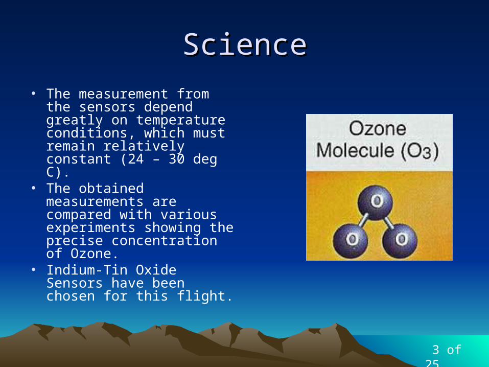
ScienceScience
• The measurement from the sensors depend greatly on temperature conditions, which must remain relatively constant (24 – 30 deg C).
• The obtained measurements are compared with various experiments showing the precise concentration of Ozone.
• Indium-Tin Oxide Sensors have been chosen for this flight.
3 of 25
TechnicalTechnical
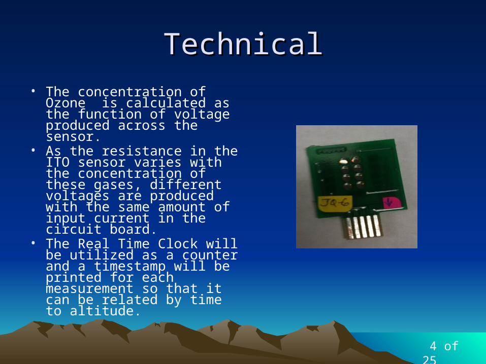
• The concentration of Ozone is calculated as the function of voltage produced across the sensor.
• As the resistance in the ITO sensor varies with the concentration of these gases, different voltages are produced with the same amount of input current in the circuit board.
• The Real Time Clock will be utilized as a counter and a timestamp will be printed for each measurement so that it can be related by time to altitude.
4 of 25

System DesignSystem Design
6 of 25

Electrical Design and Electrical Design and DevelopmentDevelopment
Sensors/Sensor InterfacingSensors/Sensor InterfacingControl ElectronicsControl Electronics
Power SupplyPower SupplyPower BudgetPower Budget
5 of 25

Sensors/Sensor InterfacingSensors/Sensor Interfacing
7 of 25

Control ElectronicsControl ElectronicsBalloonSATBalloonSAT
8 of 25

Kapton HeaterKapton Heater
9 of 25

Power SupplyPower Supply
10 of 25
Power BudgetPower Budget
11 of 25
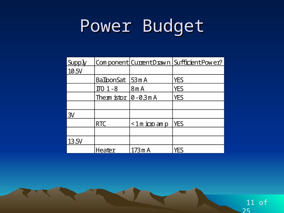
Supply Component Current Drawn Suffi cient Power?10.5V
BalloonSat 53 mA YESITO 1 - 8 8 mA YESThermistor 0 - 0.3 mA YES
3VRTC < 1 micro amp YES
13.5VHeater 173 mA YES

Software DesignSoftware Design
Data Format and StorageData Format and Storage
Flight SoftwareFlight Software
12 of 25

Data Format and StorageData Format and Storage
• EEPROM will store all data collected on flight
• EEPROM stores addresses for flight software
Byte # Data Stored0 Original Address1 Current Address
13 of 25
Byte # Data Stored ADC ADC Channel1 - 8 ITOs 2 CH1 - CH8
9 THERM 1 CH110 HOUR N/A N/A11 MINUTE N/A N/A12 SECOND N/A N/A

Flight SoftwareFlight Software
• Read “original address” from EEPROM Address $0000
• Read RTC – 3 bytes
• Read all ITO sensors and Thermistor– 9 bytes
• Store all data from reading • Store current address in
EEPROM Address $0000• Repeat loop until current
address equals 8170– (current_address =
original_address)– LED flashes once per second
14 of 25

Thermal DesignThermal Design
• ITO Sensors must maintain temperatures between 24 and 30 degrees Celsius
• Kapton Heater• Requires
approximately 1W
16 of 25
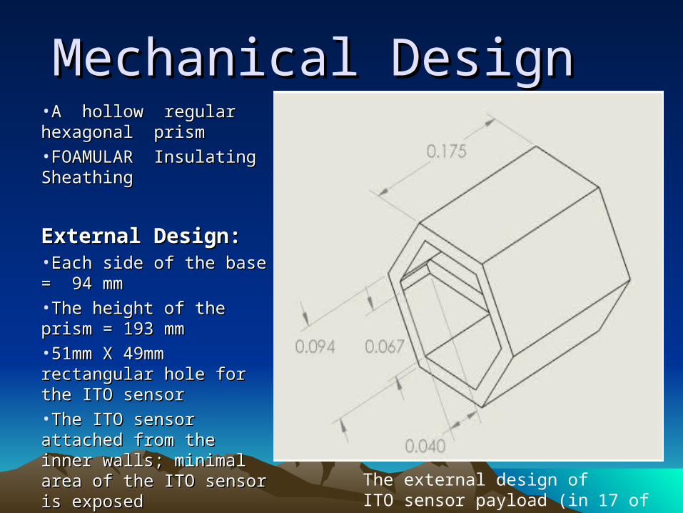
Mechanical DesignMechanical Design•A hollow regular hexagonal A hollow regular hexagonal prismprism
•FOAMULAR Insulating FOAMULAR Insulating SheathingSheathing
External Design:External Design:•Each side of the base = 94 Each side of the base = 94 mmmm
•The height of the prism = 193 The height of the prism = 193 mmmm
•51mm X 49mm rectangular 51mm X 49mm rectangular hole for the ITO sensorhole for the ITO sensor
•The ITO sensor attached The ITO sensor attached from the inner walls; minimal from the inner walls; minimal area of the ITO sensor is area of the ITO sensor is exposedexposed
The external design of ITO sensor payload (in m) 17 of 25

Internal Design:
• Rectangular- shaped foam (thickness = 18 mm) bisects the internal payload in two– Heater Batteries,
Heater, ITO sensors, BalloonSat
– BalloonSat Batteries, Sensor Interfacing Board
• Kapton Heater attached to the back of the sensor with thermal paste
Internal Divider with BalloonSAT (in m)
18 of 25

a) Side where ITO sensor is attached (in m)
b) Side where ITO sensor is attached with ITO sensor (in m)
19 of 25
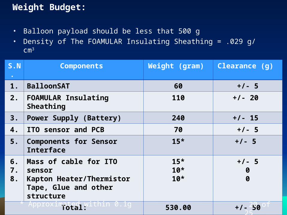
Weight Budget:
• Balloon payload should be less that 500 g
• Density of The FOAMULAR Insulating Sheathing = .029 g/ cm3
S.N.
Components Weight (gram) Clearance (g)
1. BalloonSAT 60 +/- 5
2. FOAMULAR Insulating Sheathing 110 +/- 20
3. Power Supply (Battery) 240 +/- 15
4. ITO sensor and PCB 70 +/- 5
5. Components for Sensor Interface 15* +/- 5
6.7.8.
Mass of cable for ITO sensorKapton Heater/ThermistorTape, Glue and other structure
15*10*10*
+/- 500
Total: 530.00 +/- 50
* Approximated within 0.1g 20 of 25

CalibrationsCalibrations
21 of 25

CalibrationsCalibrations
21 of 25

Ground SoftwareGround Software
• Save into text file
• Use Microsoft Excel
• Algorithms pre-programmed
22 of 25

Risk ManagementRisk Management
User BacklashMalfunctioning of
ITO sensor
Cold Solder JointUnexpected
Weather
Software Malfunctioning
System Freezing
Bad Landing (Not on ground) Batteries DrainedHardware
Malfunctioning
23 of 25
PROBABILITY
SEVERITY

Special ThanksSpecial Thanks
25 of 25