Embed Size (px)
Citation preview
.—A
IS 14700 (Part 4/See 15) :2001 /,
IEC 61000-4-1 5(1 997)3
q
;.’, ,:{
Wxfh?mm
n q
$“-.,:
.,
~ TF’Rml (&JR’??)
Indian Standard
ELECTROMAGNETIC COMPATIBILITY (EMC)PART 4 TESTING AND MEASUREMENT TECHNIQUES
Section 15 Flickermeter — Functional and Design Specifications
Ics 33.100
,. -
0 BIS 2001
BUREAU OF IN DIANSTA ND ARDSMANAK BHAVAN, 9 BAHADUR SHAH ZAFAR MARG
NEW DELHI 110002
September 2001 Price Group 8
I
Electromagnetic Compatibility Sectional Committee, LTD 22
NATIONAL FOREWORD
This Indian Standard (Part 4/See 15) which is identical with IEC 61000-4-15 (1997) ‘Electromagneticcompatibility (EMC) — Part 4: Testing and measurement techniques — Section 15: Flickermeter —Functional and design specifications’ issued by the International Electrotechnical Commission (lEC)was adopted by the Bureau of Indian Standards on the recommendation of the ElectromagneticCompatibility Sectional Committee and approval of the Electronics and Telecommunication DivisionCouncil.
In the adopted standard, certain conventions are not identical to those used in Indian Standards.Attention is particularly drawn to the following:
a) Wherever the words ‘International Standard’ appear referring to this standard, they should beread as ‘Indian Standard’.
b) Comma (,) has been used as a decimal marker while in Indian Standards, the current practiceis to use a point (.) as the decimal marker.
CROSS REFERENCES
In this adopted standard, reference appears to certain International Standards for which IndianStandards also exist. The corresponding Indian Standards which are to be substituted in their placeare listed below along with their degree ;f equivalence for the editions indicated:
/nternationa/ CorrespondingStandard Indian Standard
IEC 60068-2-1 :1990 Environmental IS 9000 (Part 2/See 1 to 4) :1977testing — Part 2: Tests — Tests A: Basic environmental testing proceduresCold for electronic and electrical items:
Part 2 Cold test
IEC 60068-2-2:1974 Environmental IS 9000 (Part 3/See 1 to 5) : 1977testing — Part 2: Tests — Tests B: Dry Basic environmental testing proceduresheat for electronic a,nd electrical items:
Part 3 Dry heat test
IEC 60068-2-3 : 1969 Environmental IS 9000 (Part 4) : 1979 Basictesting — Part 2: Tests — Test Ca: environmental testing procedures forDamp heat, steady state electronic and electrical items: Part 4
Damp heat (steady state)
IEC 60068-2-14: 1984 Environmental IS 9000 (Part 14/See 1 to 3) :1988testing — Part 2: Tests — Test N: Basic environmental testing proceduresChange of temperature for electronic and electrical items:
Part 14 Test N: Change of temperature
IEC 61000-3-3: 1994 Electromagnetic IS 14700 (Part 3/See 3) :1999 Electro-compatibility (EMC) — Part 3: Limits —Section 3: Limitation
magnetic compatibility (EMC): Part 3of voltage Limits, Section 3 Limitation of voltage
fluctuations and flicker in low-voltage fluctuations and flicker in low-voltagesupply systems for equipment with supply systems for equipment withrated currents 16 A rated current g 16 A
Degree ofEquivalence
TechnicallyEquivalent
do
do
do
Identical
.-
.
(Continued on third cover)
IS 14700 (Pat-t 4/See 15):2001IEC 61000-4-15(1997)
Indian Standard
ELECTROMAGNETIC COMPATIBILITY (EMC)PART 4 TESTING AND MEASUREMENT TECHNIQUES
Section 15 Flickermeter — Functional and Design Specifications
1 Scope and object
This section of IEC 61000-4 gives a functional andapparatus intended to indicate the correct flickerfluctuation waveforms. Information is presented
design specification forperception level for all
flicker measuringpractical voltage
to enable such an instrument to beconstructed. A method is given for the evaluation of flicker severity on the basis of the output offlickermeters complying with this standard.
This section is based on specifications prepared by the “Disturbances” working group of theInternational Union for Electroheat (UIE) and published in 1992. Consequently the flickermeterspecifications in this section relate only to measurements of 230 V, 50 Hz inputs; specificationsfor other voltages and other frequencies are under consideration.
The object of this section is to provide basic information for the design and the instrumentationof an analogue or digital flicker measuring apparatus. It does not give tolerance limit values offlicker severity.
2 Normative references
The following normative documents contain provisions which, through reference in this text,constitute provisions of this section of IEC 61000-4. At the time of publication, the editionsindicated were valid. All normative documents are subject to revision, and parties toagreements based on this section of IEC 61000-4 are encouraged to investigate the possibilityof applying the most recent edition of the normative documents indicated below. Members ofIEC and ISO maintain registers of currently valid International Standards.
IEC 60068-2-1:1990, Enviromnenta/ testing – Part 2: Tests – Tests A: Co/d
IEC 60068-2-2:1974, Errvironmenta/ testing - Part 2: Tests – Tests B: Dry heaf
IEC 60068-2-3:1969, Errvironrnenta/ testing – Part 2: Tests – Test Ca: Damp heat, steady state
IEC 60068-2-14:1984, Environments/ testing – Part 2: Tests – Test N: Change of temperature
IEC 61000-3-3:1994, Electromagnetic compatibility (EMC) – Part 3: Limits – Section 3:Limitation of voltage fluctuations and flicker in /ow-vo/tage supply systems for equipment withrated current < 16A
..
1
I
IS 14700 (Part 4/See 15):2001IEC 61000-4-15 (1997)
.. —
IEC 61000-4-2:1995, Electromagnetic compatibility (EMC) – Part 4: Testing and measurementtechniques – Section 2: Electrostatic discharge immunity test
IEC 61000-4-3:1995, Electromagnetic compatibility (EMC) – Part 4: Testing and measurementtechniques – Section 3: Radiated, radio-frequency, electromagnetic field immunity test
IEC 61000-4-4:1995, Electromagnetic compatibility (EMC) – Part 4: Testing and measurementtechniques – Section 4.’ E/ectrica/ fast transient/burst immunity test
IEC 61000-4-5:1995, Electromagnetic compatibility (EMC) – Part 4: Testing and measurementtechniques – Section 5: Surge immunity test
IEC 61000-4-6:1996, Electromagnetic compatibility (EMC) – Part 4: Testing and measurementtechniques – Section 6: Immunity to conducted disturbances induced by radio-frequency fields
IEC 61000-4-8:1993, Electromagnetic compatibility (EMC) – Part 4: Testing and measurementtechniques – Section 8: Power frequency magnetic field immunity test
IEC 61000-4-9:1993, Electromagnetic compatibility (EMC) – Part 4: Testing and measurementtechniques – Section 9: Pulse magnetic field immunity test
IEC 61000-4-11:1994, Electromagnetic compatibility (EMC) - Part 4: Testing and measurementtechniques – Section 11: Voltage dips, short interruptions and voltage variations immunity tests
IEC 61000-4-12:1995, Electromagnetic compatibility (EMC) – Part 4: Testing and measurementtechniques – Section 12: Oscillatory waves immunity test
IEC 61010-1:1990, Safety requirements for electrical equipment for measurement, contro/, andlaboratory use – Part 1: General requirements
IEC 61326-1:1997, Electrical equipment for measurement, control and laboratory use –Electromagnetic compatibility (EMC) requirements – Part 1: General requirements
IEC 61326-10, — Electrical equipment for measurement, control and laboratory use –Electromagnetic compatibility (EMC) requirements – Part 10: Particular requirements forequipment used in industrial locations *
.3 Description of the instrument
3.1 General
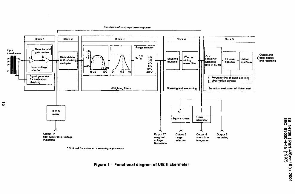
The description given below is based on an analogue implementation.
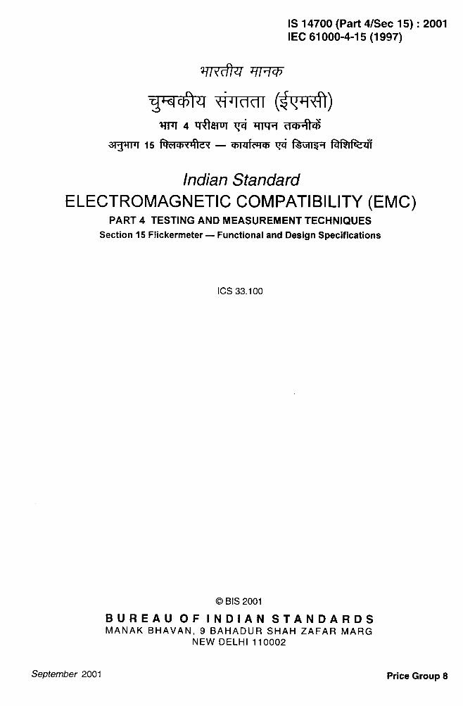
The flickermeter architecture is described by the block diagram of figure 1, and can be dividedinto two parts, each performing one of the following tasks:
simulation of the response of the lamp-eye-brain chain;
– on-line statistical analysis of the flicker signal and presentation of the results.
The first task is performed by blocks 2, 3 and 4 of figure 1, while the second task isaccomplished by block 5.
-.-+
7.*,,‘.
“ To be published 2
IS 14700 (Part 4/See 15):2001IEC 61000-4-15(1997)
. . .—
3.2 Block 1 – Input voltage adaptor and calibration checking circuit
This block contains a signal generator to check the calibration of the flickermeter on site and avoltage adapting circuit that scales the mean r.m. s. value of the input mains frequency voltagedown to an internal reference level. In this way flicker measurements can be madeindependently of the actual input carrier voltage level and expressed as a per cent ratio. Tapson the input transformer establish suitable input voltage ranges to keep the input signal to thevoltage adaptor within its permissible range.
NOTE – In digital instruments the voltage adaption may be performed by multiplying the instantaneous input voltageby 230 V divided by the actual input voltage averaged over 60 s.
3.3 Block 2 – Square law demodulator
The purpose of this block is to recover the voltage fluctuation by squaring the input voltagescaled to the reference level, thus simulating the behaviour of a lamp.
3.4 Blocks 3 and 4 – Weighting filters, squaring and smoothing
Block 3 is composed of a cascade of two filters and a measuring range selector, which canprecede or follow the selective filter circuit.
The first filter eliminates the d.c. and double mains frequency ripple components of thedemodulator output.
The second filter is a weighting filter block that simulates the frequency response to sinusoidalvoltage fluctuations of a coiled filament gas-filled lamp (60 W – 230 V) combined with thehuman visual system. The response function is based on the perceptibility threshold found ateach frequency by 50 O/. of the persons tested.
NOTE - A reference filament lamp for 100-130 V systems would have a different frequency response and wouldrequire a corresponding adjustment of the weighting filter. The characteristics of discharge lamps are totallydifferent, and substantial modifications to this standard would be necessary if they were taken into account.
Block 4 is composed of a squaring multiplier and a first order low-pass filter. The human flickersensation via lamp, eye and brain is simulated by the combined non-linear response of blocks2, 3 and 4.
Block 3 alone is based on the borderline perceptibility curve for sinusoidal voltage fluctuations;the correct weighting of non-sinusoidal and stochastic fluctuations is achieved by anappropriate choice of the complex transfer function for blocks 3 and 4. Accordingly the correctperformance of the model has also been checked with periodic rectangular signals as well aswith transient signals.
The output of block 4 represents the instantaneous flicker sensation.
3.5 Block 5 – On-line statistical analysis
Block 5 incorporates a microprocessor that performs an on-line analysis of the flicker level,thus allowing direct calculation of significant evaluation parameters.
A suitable interface allows data presentation and recording. The use of this block is related tomethods of deriving measurements of flicker severity by statistical analysis. The statisticalanalysis, performed on line by block 5 shall be made by subdividing the amplitude of the flickerlevel signal into a suitable number of classes. The flicker level signal is sampled at a constantrate.
3
.
.. .—IS 14700 (Part 4/see 15):2001IEC 61000-4-15(1997)
Every time that the appropriate value occurs, the counter of the corresponding classincremented bv one. In this wav, the freauencv distribution function of the incmt values
isis
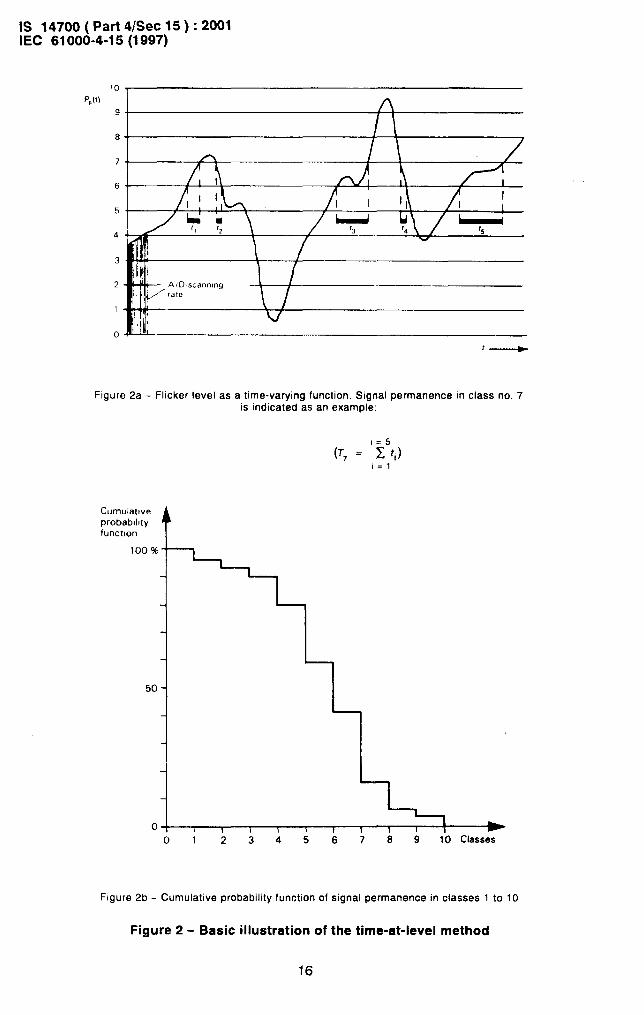
obtained. By choosing a scanning frequency of at least twice the maximum flicker frequency,the final result at the end of the measuring interval represents the distribution of flicker levelduration in each class. Adding the content of the counters of all classes and expressing thecount of each class relative to the total gives the probability density function of the flickerlevels.
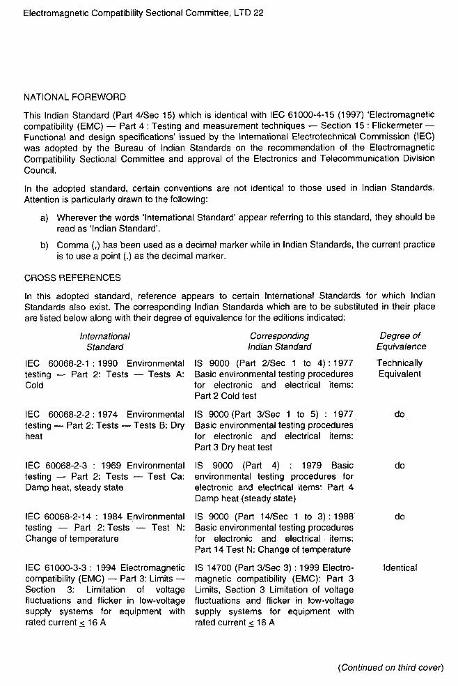
From this function is obtained the cumulative probability function used in the time-at-levelstatistical method. Figure 2 schematically represents the statistical analvsis method, limited forsimplicity of presentation to 10 classes.
From the cumulative probability function, significant statistical values can be obtained such asmean, standard deviation, flicker level being exceeded for a given percentage of time or,alternately, the percentage of time that an assigned flicker level has been exceeded
The observation period is defined by two adjustable time intervals: T~h~~tand ~On~.
The long interval defines the total observation time and is always a multiple of the shortinterval:
( ~long = n x ‘short)
For on-line processing, immediately after conclusion of each short time interval, the statisticalanalysis of the next interval is started and the results for the expired interval are madeavailable for output. In this way, n short time analyses will be available for a given observationperiod ~on~ together with the results for the total interval. Cumulative probability function plots
should preferably be made by using a Gaussian normal distribution scale.
3.6 O.@uts
3.6.1 General
The flickermeter diagram in figure 1 shows a number of outputs between blocks 1 and 5. Theoutputs marked with an asterisk are not essential, but may allow a full exploitation of theinstrument potential for the investigation of voltage fluctuations. Further optional outputs maybe considered.
3.6.2 Output 1
The aim of optional output 1 and its associated r.m.s. voltmeter is to display the voltagefluctuation waveform in terms of changes in r.m.s. value of the input voltage. This can beachieved by squaring, integrating between zero crossings on each half-cycle and square-rooting the signal.
In order to observe small voltage changes with good resolution, an adjustable d.c. offset andrectification should be provided.
3.6.3 0utput2
Output 2. is optional and mainly intended for checking the response of block 3 and makingadjustments.
.—
4
IS 14700 (Part 4/See 15):2001IEC 61000-4-15(1997)
3.6.4 Output3
Output 3 is optional and gives an instantaneous linear indication of the relative voltage changeAV/V expressed as per cent equivalent of an 8,8 Hz sinusoidal wave modulation. This output isuseful when selecting the proper measuring range.
3.6.5 Output 4
Output 4 is optional and gives the 1 min integral of the instantaneous flicker sensation.
3.6.6 Output 5
Output 5 is mandatory; it represents the instantaneous flicker sensation and can be recordedon a strip-chart recorder for a quick on-site evaluation, or on magnetic tape for long-durationmeasurements and for later processing.
3.6.7 Output 6
Output 6 in block 5 is mandatory and is connected to a serial digital interface suitable for aprinter and a magnetic tape recorder. Analogue plots of the cumulative probability function canbe obtained directly from this block by using another digital-to-analogue converting interface.
4 Specification
4.1 Analogue response
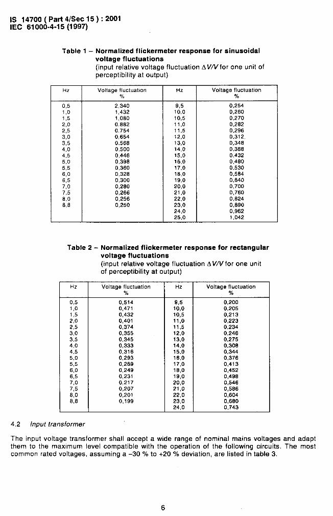
The overall analogue response from the instrument input to the output of block 4 is given intables 1 and 2 for sinusoidal and rectangular voltage fluctuations. One unit output from block 4corresponds to the reference human flicker perceptibility threshold. The response is centred at8,8 Hz for sinusoidal modulation.
.-
.-.
The prescribed accuracy is achieved if the input values for sine and square-wave modulationsare within ~ 5 % of the tabulated values, for an output of one unit of perceptibility.
5
IS 14700 (Part 4/See 15):2001IEC 61000-4-15(1997)
..-
Table 1 - Normalized flickermetervoltage fluctuations
response for sinusoidal
(input relatiVe VOltage fluctuation AV/Vfor one unit ofperceptibility at output)
Hz Voltage fluctuation Hz Voltage fluctuation% “h
0,5 2,340 9,5 0,2541,0 1,432 10,0 0,2601,5 1,080 10,5 0,2702,0 0,882 11,0 0,2822,5 0,754 11,5 0,2963,0 0,654 12,0 0,3123,5 0,568 13,0 0,3484,0 0,500 14,0 0,3884,5 0,446 15,0 0,4325,0 0,398 16,0 0,4805,5 0,360 17,0 0,5306,0 0,328 18,0 0,5846,5 0,300 19,0 0,64CI7,0 0,280 20,0 0,7007,5 0,266 21,0 0,7608,0 0,256 22,0 0,8248,8 0,250 23,0 0,890
24,0 0,96225,0 1,042
Table 2- Normalized flickermeter response far rectangularvoltage fluctuations
(input relative voltage fluctuation AV/Vfor one unitof perceptibility at output)
Hz Voltage fluctuation Hz Voltage fluctuation70 Y.
0,5 0,514 9,5 0,2001,0 0,471 10,0 0,2051,5 0,432 10,5 0,2132,0 0,401 11,0 0,2232,5 0,374 11,5 0,2343,0 0,355 12,0 0,2463,5 0,345 13,0 0,2754,0 0,333 14,0 0,3084,5 0,316 15,0 0,3445,0 0,293 16,0 0,3765,5 0,269 17,0 0,4136,0 0,249 18,0 0,4526,5 0,231 19,0 0,4987,0 0,217 20,0 0,5467,5 0,207 21,0 0,5868,0 0,201 22,0 0,6048,8 0,199 23,0 0,680
24,0 0,743
4.2 h?put transformer
The input voltage transformer shall accept a wide range of nominal mains voltages and adapt
:
-—-!?“-
{
.-
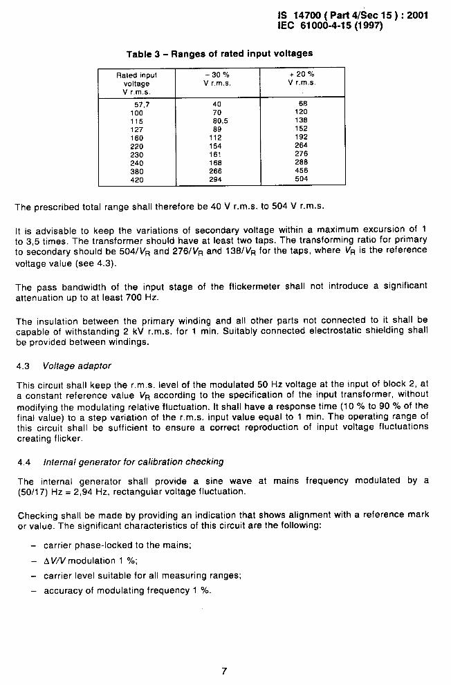
them to the maximum level compatible with the operation of the following circuits. The mostcommon rated voltages, assuming a –30 Y. to +20 “A deviation, are listed in table 3.
6
IS 14700 (Part 4/See 15):2001IEC 61000-4-15(1997)
-.. .—A
Table 3- Ranges of rated input voltages
Rated input -30 v. + 20 %voltage V r.m.s. V r.m.s.
V r.m.s.
57,7 40 68100 70 120115 60,5 138127 69 152160 112 192220 154 264230 161 276240 166 286360 266 456420 294 504
The prescribed total range shall therefore be 40 V r.m.s. to 504 V r.m.s.
It is advisable to keep the variations of secondary voltage within a maximum excursion of 1to 3,5 times. The transformer should have at least two taps. The transforming ratio for primaryto secondary should be 504/VR and 276/VR and 138/VR for the taps, where VR is the reference
voltage value (see 4.3).
The pass bandwidth of the input stage of the flickermeter shall not introduce a significantattenuation up to at least 700 Hz.
The insulation between the primary winding and all other parts not connected to it shall becapable of withstanding 2 kV r.m.s. for 1 min. Suitably connected electrostatic shielding shallbe provided between windings.
4.3 Voltage adaptor
This circuit shall keep the r.m.s. level of the modulated 50 Hza constant reference value VR according to the specification
voltage at the input of block 2, atof the input transformer, without
modifying the modulating relative fluctuation. It shall have a response time (10 9’. to 90 Y. of thefinal value) to a step variation of the r.m.s. input value equal to 1 min. The operating range ofthis circuit shall be sufficient to ensure a correct reproduction of input voltage fluctuationscreating flicker.
4.4 Internal generator for calibration checking
The internal generator shall provide a sine wave at mains frequency modulated by a(50/17) Hz = 2,94 Hz, rectangular voltage fluctuation.
Checking shall be made by providing an indication that shows alignment with a reference markor value. The significant characteristics of this circuit are the following:
carrier phase-locked to the mains;
– AV/Vmodulation 1 Y.;
carrier level suitable for all measuring ranges;
accuracy of modulating frequency 1 Yo.
. .
7
IS 14700 ( Pat-t 4/See 15 ) :2001IEC 61 000-4-15(1 997)
—..—
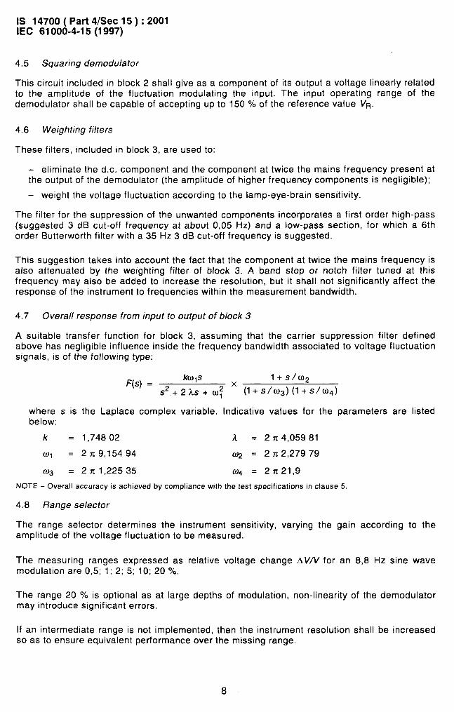
4.5 Squaring demodulator
This circuit included in block 2 shall give as a component of its output a voltage linearly relatedto the amplitude of the fluctuation modulating the input. The input operating range of thedemodulator shall be capable of accepting up to 150 O/. of the reference value VR.
4.6 Weighting filters
These filters, included in block 3, are used to:
eliminate the d.c. component and the component at twice the mains frequency present atthe output of the demodulator (the amplitude of higher frequency components is negligible);
— weight the voltage fluctuation according to the lamp-eye-brain sensitivity.
The filter for the suppression of the unwanted components incorporates a first order high-pass(suggested 3 dB cut-off frequency at about 0,05 Hz) and a low-pass section, for which a 6thorder Butterworth filter with a 35 Hz 3 dB cut-off frequency is suggested.
This suggestion takes into account the fact that the component at twice the mains frequency isalso attenuated by the weighting filter of block 3. A band stop or notch filter tuned at thisfrequency may also be added to increase the resolution, but it shall not significantly affect theresponse of the instrument to frequencies within the measurement bandwidth.
4.7 Overall response from input to output of block 3
A suitable transfer function for block 3, assuming that the carrier suppression filter definedabove has negligible influence inside the frequency bandwidth associated to voltage fluctuationsignals, is of the following type:
F(s) =kwls l+s/w2
S2+2AS+W; x (l+s/w3)(l+s/w~)
where s is the Laplace complex variable. Indicative values for the parameters are listedbelow:
k = 1,74802 A = 2 n 4,05981
01 = 2x9,15494 U2 = 2 n 2,27979
ln3 = 2rcl,22535 fL)4 = 2 x21,9
NOTE - Overall accuracy is achieved by compliance with the test specifications in clause 5.
4.8 Range selector
The range selector determines the instrument sensitivity, varying the gain according to theamplitude of the voltage fluctuation to be measured.
The measuring ranges expressed as relative voltage change AV/V for an 8,8 Hz sine wavemodulation are 0,5; 1; 2; 5; 10; 209’0.
The range 20 Y. is optional as at large depths of modulation, non-linearity of the demodulatormay introduce significant errors.
. .
If an intermediate range is not implemented, then the instrument resolution shall be increasedso as to ensure equivalent performance over the missing range.
8
IS 14700 (Part 4/See 15):2001IEC 61000-4-15(1997)
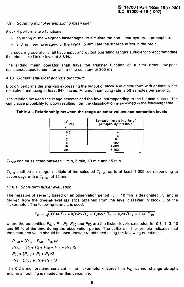
4.9 Squaring multiplier and sliding mean filter
Block 4 performs two functions:
squaring of the weighted flicker signal to simulate the non-linear eye-brain perception;
— sliding mean averaging of the signal to simulate the storage effect in the brain.
The squaring operator shall have input and output operating ranges sufficient to accommodatethe admissible flicker level at 8,8 Hz.
The sliding mean operator shall have the transfer function of a first order low-passresistance/capacitance filter with a time constant of 300 ms.
4.10 General statistical analysis procedure
Block 5 performs the analysis expressing the output of block 4 in digital form with at least 6 bitsresolution and using at least 64 classes. Minimum sampling rate is 50 samples per second.
The relation between the range selector and the level corresponding to the highest class of thecumulative probability function resulting from the classification is indicated in the following table.
Table 4- Relationship between the range selector values and sensation levels
Sensation levels in units of: (%) perceptibility threshold
0,5 41 162 645 400
10 1 60020 6400
Tshort can be selected between 1 rein, 5 rein, 10 min and 15 min.
~on~ shall be an integer multiple of the selected Tshofi up to at least 1 008, corresponding to
sev~n days with a TShO~tof 10 min.
4.10.1 Short-term flicker evaluation
The measure of severity based on an observation period Tst = 10
derived from the time-at-level statistics obtained from the levelflickermeter. The following formula is used:
min is designated PSt and is
classifier in block 5 of the
PSt = 0,0314 P03 + 00525 Pls + 0,0657 P3S + 0,28 P1OS + 0,08 P50S
where the percentiles Po,l, P1, P3, Plo and P50 are the flicker levels exceeded for 0,1; 1; 3; 10
and 50 YO of the time during the observation period. The suffix s in the formula indicates thatthe smoothed value should be used; these are obtained using the following equations:
Psos = (P30 + /’50 + P80)/3
plo~= (P6+ PB+ Plo+ /’13+ P17)/5
P3S = (P’2,2 + P3 + P4)/3
P,s = (Po,~ + /’1 + P, ,5)/3
The 0,3 s memory time-constant in the flickermeter ensures that PO,l cannot change abruptly
and no smoothing is needed for this percentile.
9
,4,
-. .—
-—--J.
. ..-
. .—
IS 14700 (Part 4/See 15):2001IEC 61000-4-15(1997)
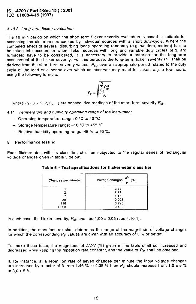
4.10.2 Long-term flicker evaluation
The 10 min period on which the short-term flicker severity evaluation is based is suitable forassessing the disturbances caused by individual sources with a short duty-cycle. Where thecombined effect of several disturbing loads operating randomly (e.g. welders, motors) has tobe taken into account or when flicker sources with long and variable duty cycles (e.g. arcfurnaces) have to be considered, it is necessary to provide a criterion for the long-termassessment of the flicker severity. For this purpose, the long-term flicker severity /’lt, shall bederived from the short-term severity values, F’~t, over an appropriate period related to the duty
cycle of the load or a period over which an observer may react to flicker, e.g. a few hours,using the following formula:
where P~ti (i = 1,2, 3, ...) are consecutive readings of the short-term severity P~t.
4.11
—
—
Temperature and humidity operating range of the instrument
Operating temperature range: O “C to 40 “C
Storage temperature range: –1 O ‘C to +55 “C
Relative humidity operating range: 457. to 95 Y..
5 Performance testing
Each flickermeter, with its classifier, shall be subjected to the regular series of rectangularvoltage changes given in table 5 below.
Table 5- Test specifications for flickermeter classifier
Changes per minute Voltage changes ~ (%)
rrnrIn each case, the flicker severity, PSt, shall be 1,00 + 0,05 (see 4.10.1).
In addition, the manufacturer shall determine the range of the magnitude of voltage changesfor which the corresponding PSt values are given with an accuracy of 5 YO or better.
To make these tests, the magnitude. of AV/V (O/.) given in the table shall be increased anddecreased while keeping the repetition rate constant, and the value of PSt shall be obtained.
If, for instance, at a repetition rate of seven changes per minute the input voltage changesare increased by a factor of 3 from 1,46 O/. to 4,38 ‘h then PSt should increase from 1,0 * 5 O/.
to 3.0 & 570.
.-
10
,#,
-. .—IS 14700 (Part 4/See 15):2001IEC 61 000-4-15(1 997)
The range over which the accuracy of 5 Y. is maintained is the working range of the classifier.
If selectable sensitivity ranges are employed in the flickermeter, then similar tests should beperformed for each range.
NOTE – The flickermeter responses to phase modulation and fluctuating harmonics are under consideration.
6 Type test and calibration specifications
6.1 General
Individual checking of all elements is generally not necessary, only the overall input-outputresponse up to block 4 shall be checked for sinusoidal and rectangular voltage fluctuations,with reference to tables 1 and 2. In addition the statistical analysis (block 5) shall be tested inaccordance with clause 5 and table 5.
The tests shall be made by changing the input modulation amplitude so that the peak value ofthe output reading is unity.
If the input modulation amplitudes found for the instrument under test coincide with thespecified values (maximum tolerance * 5 Yo), compliance with this specification is proved.
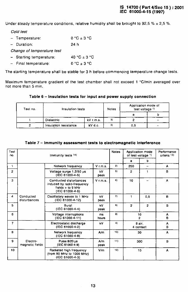
6.2 Insulation and electromagnetic compatibility tests (provisional)
Insulation tests are given in table 6 for input and power supply connections.
The tests prescribed to assess the immunity of the instrument to electromagnetic interferenceare summarized in table 7. This table contains references to existing IEC publications. Some ofthese tests are still under consideration by IEC subcommittees 77A and 77B.
.
These tests are prescribed under the assumption that the common zero reference of theelectronic circuitry is connected to case and to earth.
Tests numbered from 1 to 5 shall be performed on input and power supply connections, testnumber 6 only on power supply and tests from 7 to 10 on the instrument as a whole.
The severity levels of the tests have been selected assuming that during the normal use of theinstrument, its outputs are connected to external equipment using short and shielded cables.
For all the tests and during the application of the interference influence factors, correctoperation of the instrument shall be checked, verifying a minimum of five suitably spacedpoints of the response.
11
IS 14700 (Part 4/See 15):2001IEC 61000-4-15(1997)
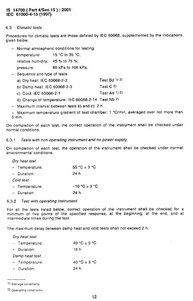
6.3 Climatic tests
. .—
-J
Procedures for climatic tests are those defined by IEC 60068, supplemented by the indicationsgiven below.
— Normal atmospheric conditions for testing:
temperature: 15 ‘cto 35 ‘c;relative humidity: 4570 to 75 70;
pressure: 86 kPa to 106 kPa.
– Sequence and type of tests:
a) Dry heat: IEC 60068-2-2 Test Bd 1) z)
b) Damp heat: IEC 60068-2-3 Test C z)
C) Cold: IEC 60068-2-1 Test Ad 1) z)
d) Change of temperature: IEC 60068-2-14 Test Nb .2)
— Maximum interval between tests b) and c): 2 h.
— Maximum temperature gradient of test chamber: 1 OC/min, averaged over not more than5 min.
On completion of each test, the correct operation of the instrument shall be checked undernormal conditions.
6.3.1 Tests with non-operating instrument and no power supply
On completion of each test, the operation of the instrument shall be checked under normalenvironmental conditions.
Dry heat test
– Temperature: 55 °c*30c
– Duration: 24 h
Co/d test
– Temperature: –10”C*3”C
– Duration: 24 h
6.3.2 Test with operating instrument
For all the tests listed below, correct operation of the instrument shall be checked for aminimum of five points of the specified response, at the beginning, at the end, and atintermediate times during the test.
The maximum delay between damp heat and cold tests shall not exceed 2 h.
Dry heat test
– Temperature: 40 °c*30c
– Duration: 16h
Damp heat test
– Temperature: 40 °c*30c
– Duration: 24 h
..
—————.——
1) Storage cond!tlons
~) Operating cond!tlons
12
-
.- .—
IS 14700( Part 4/See 15 ) :2001IEC 61 000-4-15(1 997)
Under steady temperature conditions, relative humidity shall be brought to 92,5 YO * 2,5 Y..
Cold test
– Temperature: 0°c*30c
– Duration: 24 h
Change of temperature test
– Starting temperature: 40”C*3°C
– Final temperature: o“ct3°c
The starting temperature shall be stable for 3 h before commencing temperature change tests
Maximum temperature gradient of the test chamber shall not exceed 1 OC/min averaged overnot more than 5 min.
Table 6- Insulation tests for input and power supply connection
Application mode ofTest no. Insulation tests Notes test voltage l]
a b
1 Dielectric kV r.m.s. 3) 2 —
2 Insulation resistance kV d.c. 3) 0,5
Table 7- Immunity assessment tests to electromagnetic interference
TTestno.
1
2
3
4
5
6
7
8
9
10
Application mode I Performanceof test voltage 1) criteria I 3)Immunity tests 14)
--albl
Network frequency
Voltage surge 1,2150 ps(IEC 61 000-4-5)
Conducted disturbancesinduced by radio-frequency
fields > to 9 kHz(IEC 61000-4-6)
Conducted Oscillatory waves to 1 MHzdisturbances (IEC 61 000-4-12)
Burst(IEC 61000-4-4)
V r.m.s. \ z)
kV I 5)
peak2111B
-1--V r.m.s. L3
kV 7)
10 — A
1 0,5 B
2 2 B
10 A
%--h-+I Voltage interruptions
(IEC 61000-4-11) 2 IB
I Electrostatic discharge(IEC 61000-4-2)
kV I 4) 8 air, I A4 contact B
I Network frequency(IEC 61 000-4-8)
A/m I 10) 30 I A
Electro- 1 Pulse 8/20 psmagnetic fields (IEC 61000-4-9)
A/m
I11)
peak300 I B
Radiated high frequency(from 80 MHz to 1000 MHz)
(IEC 61000-4-3)
10 A
13
IS 14700 (Part 4/See 15):2001IEC 61000-4-15(1997)
* &
.-—
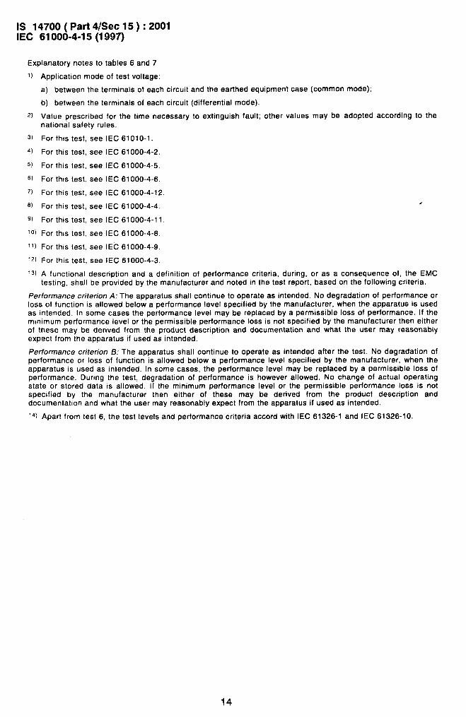
Explanatory notes to tables 6 and 7
1) Application mode of test voltage:
a) between the terminals of each circuit and the earthed equipment case (common mode);
b) between the terminals of each circuit (differential mode).
z) Value prescribed for the time necessary to extinguish fault;national safety rules.
s) For this test, see IEC 61010-1.
4) For this test, see IEC 61000-4-2.
5) For this test, see IEC 61000-4-5.
G) For this test, see IEC 61000-4-6.
7) For this test, see IEC 61000-4-12.
a) For this test, see IEC 61000-4-4.
9) For this test, see IEC 61000-4-11,
10) For this test, see IEC 61000-4-8.
It) For this test, see IEC 61000-4-9.
12) For this test. see IEC 61000-4-3,
other values may be adopted according to the
4
13) A functional description and a definition Of performance criteria, during, or as a consequence Of, the EMC
testing, shall be provided by the manufacturer and noted in the test report, based on the following criteria.
Performance criterion A: The apparatus shall continue to operate as intended. No degradation of performance orloss of function is allowed below a performance level specified by the manufacturer, when the apparatus is usedas intended. In some cases the performance level may be replaced by a permissible loss of performance. If theminimum performance level or the permissible performance loss is not specified by the manufacturer then eitherof these may be derived from the product description and documentation and what the user may reasonablyexpect from the apparatus if used as intended.
Performance criterion B: The apparatus shall continue to operate as intended after the test. No degradation ofperformance or loss of function is allowed below a performance level specified by the manufacturer, when theapparatus is used as intended. In some cases, the performance level may be replaced by a permissible loss ofperformance. During the test, degradation of performance is however allowed. No change of actual operatingstate or stored data is allowed. If the minimum performance level or the permissible performance loss is notspecified by the manufacturer then either of these may be derived from the product description anddocumentation and what the user may reasonably expect from the apparatus if used as intended.
14) Apart from test 6, the test levels and performance criteria accord with IEC 61326-1 and IEC 61326-10.
14
Is147m
(Pati4/sec15):2001
IEC
61000-4-15(1
997)
I
1
,I
II
m
..—
15
IS 14700 (Part 4/See 15):2001IEC 61000-4-15(1997)
10
9
8
7
6
5
A
3
2
0
n / \
I I
II I1,
, 1
/ Ak \ / u\ / b
i--- AI D-scannma ~-
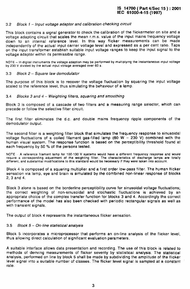
Figure 2a- Flicker level asatime-varying function. Signal permanence in class no, 7is indicated as an example:
,=5(T7 = ~ti)
1=1
Cumulativeprobablhtyfunction
100%
50
0., ! I I 1 I 1 I 1 I b01234567 89
110 Classes
Figure 2b – Cumulative probability function of signal permanence in classes 1 to 10
Figure 2- Basic illustration of the time-at-level
16
.4-
IS 14700 (Part 4/See 15):2001IEC 61 000-4-15(1 997)
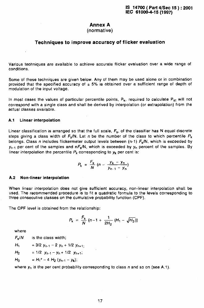
Annex A(normative)
Techniques to improve accuracy of flicker evaluation
Various techniques are available to achieve accurate flicker evaluation over a wide range ofconditions.
Some of these techniques are given below. Any of them may be used alone or in combinationprovided that the specified accuracy of * 5% is obtained over a sufficient range of depth ofmodulation of the input voltage.
In most cases the values of particular percentile points, pk, required to calculate P~t will f’IOt
correspond with a single class and shall be derived by interpolation (or extrapolation) from theactual classes available.
A.1 Linear interpolation
Linear classification is arranged so that the full scale, F~, of the classifier has N equal discrete
steps giving a class width of F~/N. Let n be the number of the class to which percentile /’k
belongs. Class n includes flickermeter output levels between (n-1) FJN, which is exceeded by
Yn-1 per cent of the samples and nFJN, which is exceeded by Yn percent of the samples. BYlinear interpolation the percentile /’k corresponding to yk per cent is:
pk = ;(n - J’k-yn)Yn-1 – Yn
A.2 Non-iinear interpolation
When linear interpolation does not give sufficient accuracy, non-linear interpolation shall beused. The recommended procedure is to fit a quadratic formula to the levels corresponding tothree consecutive classes on the cumulative probability function (CPF).
The CPF level is obtained from the relationship:
Pk = ~ (n–l + & (H, - JzJ)
where
FSIN is the class width;
HI = 3/2 yn.l – 2 Yn + 1/2 Yn+l;
H2 = 1/2 Yfl-1 ‘Yfl+ 1/2 Yn+l;
H3 = HI’ – 4 Hz (Yn-1 – Yk)j
where yn is the per cent probability corresponding to class n and so on (see A. I).
17
—
—.“,.-
..-
/
.&<
IS 14700 (Part 4/See 15):2001IEC 61 000-4-15(1 997)
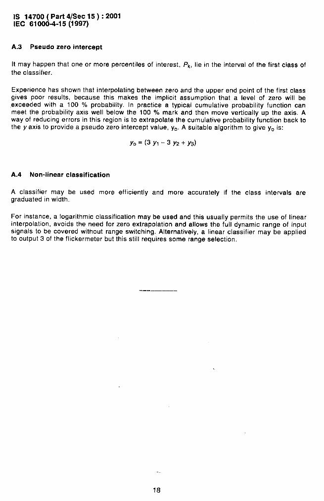
A.3 Pseudo zero intercept
It may happen that one or more percentiles of interest, ~k, lie in the interval of the first class of
the classifier.
Experience has shown that interpolating between zero and the upper end point of the first classgives poor results, because this makes the implicit assumption that a level of zero will beexceeded with a 100 ‘!4. probability. In practice a typical cumulative probability function canmeet the probability axis well below the 100 % mark and then move vertically up the axis. Away of reducing errors in this region is to extrapolate the cumulative probability function back tothe y axis to provide a pseudo zero intercept value, yo. A suitable algorithm to give y. is:
YO=(3YI–3Y2+Y3)
A.4 Non-linear classification
A classifier may be used more efficiently and more accurately if the class intervals aregraduated in width.
.....
For instance, a logarithmic classification may be used and this usually permits the use of linearinterpolation, avoids the need for zero extrapolation and allows the full dynamic range of inputsignals to be covered without range switching. Alternatively, a linear classifier may be appliedto output 3 of the flickermeter but this still requires some range selection.
+---
18
, 4
-—
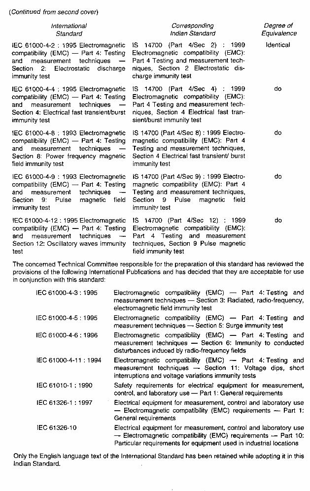
(Continued from second cover)
InternationalStandard
IEC 61000-4-2: 1995 Electromagneticcompatibility (EMC) — Part 4: Testingand measurement techniques —Section 2: Electrostatic dischargeimmunity test
IEC 61000-4-4: 1995 Electromagneticcompatibility (EMC) — Part 4: Testingand measurement techniques —Section 4: Electrical fast transientiburstimmunity test
IEC 61000-4-8: 1993 Electromagneticcompatibility (EMC) — Part 4: Testingand measurement techniques —Section 8: Power frequency magneticfield immunity test
IEC 61000-4-9: 1993 Electromagneticcompatibility (EMC) — Parl 4: Testingand measurement techniques —Section 9: Pulse magnetic fieldimmunity test
IEC 61000-4-12:1995 Electromagneticcompatibility (EMC) — Part 4: Testingand measurement techniques —Section 12: Oscillatory waves immunitytest
Corresponding Degree ofIndian Standard Equivalence
IS 14700 (Part 4/See 2) : 1999 IdenticalElectromagnetic compatibility (EMC):Part 4 Testing and measurement tech-niques, Section 2 Electrostatic dis-charge immunity test
IS 14700 (Part 4/See 4) : 1999Electromagnetic compatibility (EMC):Part 4 Testing and measurement tech-niques, Section 4 Electrical fast tran-sient/burst immunity test
IS 14700 (Part 4/See 8): 1999 Electro- domagnetic compatibility (EMC): Part 4Testing and measurement techniques,Section 4 Electrical fast transient burstimmunity test
IS 14700 (Part 4/See 9) :1999 Electro- domagnetic compatibility (EMC): Part 4Testing and measurement techniques,Section 9 Pulse magnetic fieldimmunity test
IS 14700 (Pafl 4/See 12) : 1999Electromagnetic compatibility (EMC):Part 4 Testing and measurementtechniques, Section 9 Pulse magneticfield immunity test
do
do
The concerned Technical Committee responsible for the preparation of this standard has reviewed theprovisions of the following International Publications and has decided that they are acceptable for usein conjunction with this standard:
IEC 61000-4-3:1995
IEC 61000-4-5:1995
IEC 61000-4-6:1996
IEC 61000-4-11:1994
IEC 61010-1:1990
IEC 61326-1:1997
IEC 61326-10
Electromagnetic compatibility (EMC) — Part 4: Testing andmeasurement techniques — Section 3: Radiated, radio-frequency,electromagnetic field immunity test
Electromagnetic compatibility (EMC) — Part 4: Testing andmeasurement techniques — Section 5: Surge immunity test
Electromagnetic compatibility (EMC) — Part 4: Testing andmeasurement techniques — Section 6: Immunity to conducteddisturbances induced tYyradio-frequency fields
Electromagnetic compatibility (EMC) — Part 4: Testing andmeasurement techniques — Section 11: Voltage dips, shortinterruptions and voltage variations immunity tests
Safety requirements for electrical equipment for measurement,control, and laboratory use — Part 1: General requirements
Electrical equipment for measurement, control and laboratory use— Electromagnetic compatibility (EMC) requirements — Part 1:General requirements
Electrical ecrui~ment for measurement, control and Iaboratorv use— Electromagnetic compatibility (EMC) requirements — Pa~ 10:Particular requirements for equipment used in industrial locations
Only the English language text of the International Standard has been retained while adopting it in thisIndian Standard.
i’.&
Bureau of Indian Standards
BIS is a statutory institution established under the Bureau of /ndian Standards Act, 1986 to promoteharmonious development of the activities of standardization, marking and quality certification of goodsand attending to connected matters in the country.
Copyright
BIS has the copyright of all its publications. No part of these publications may be reproduced in anyform without the prior permission in writing of BIS. This does not preclude the free use, in the course
of implementing the standard, of necessary details, such as symbols and sizes, type or grade
designations. Enquiries relating to copyright be addressed to the Director (Publications), BIS.
Review of Indian Standards
Amendments are issued to standards as the need arises on the basis of comments. Standards arealso reviewed periodically; a standard along with amendments is reaffirmed when such review indi-cates that no changes are needed; if the review indicates that changes are needed, it is taken up forrevision. Users of Indian Standards should ascertain that they are in possession of the latest amend-ments or edition by referring to the latest issue of ‘BIS Catalogue’ and ‘Standards: Monthly Additions’.
This Indian Standard has been developed from Doc : No. LTD 22 ( 188I ).
Amendments Issued Since Publication
Amend No. Date of Issue Text Affected
BUREAU OF INDIAN STANDARDS
Headquarters :
Manak Bhavan, 9 Bahadur Shah Zafar Marg, New Delhi 110002 Telegrams : Manaksanstha
Telephones :3230131,3233375,3239402 (Common to all offices)
Regional Offices : Telephone
Central :
Eastern :
Northern :
Southern :
Western :
Branches :
Manak Bhavan, 9 Bahadur Shah Zafar Marg
{
3237617NEW DELHI 110002 3233841
1/14 C.I.T. Scheme Vll M, V. 1.P. Road, Kankurgachi
{
3378499, 3378561KOLKATA 700054 3378626, 3379120
SCO 335-336, Sector 34-A, CHANDIGARH 160022
{
603843602025
C.I.T. Campus, IV Cross Road, CHENNAI 600113
{
2541216,25414422542519,2541315
Manakalaya, E9 MlDC, Marol, Andheri (East)
{
8329295, 8327858MUMBAI 400093 8327891,8327892
AHMEDABAD. BANGALORE. BHOPAL. BHUBANESHWAR. CO IMBATORE.FARIDABAD. GHAZIABAD. GUWAHATI. HYDERABAD. JAIPUR. KANPUR.LUCKNOW. NAGPUR. NALAGARH. PATNA. PUNE. RAJKOT. THIRUVANANTHAPURAM.
Printed at Prabhat Offset Press, New Delhi-2
D,..’>”
I
k
f Ii