Embed Size (px)
Citation preview
I
For Official use only
GOVERNMENT OF INDIA MINISTRY OF RAILWAYS
(Railway Board)
INDIAN RAILWAY STANDARD
SPECIFICATION FOR FABRICATION AND ERECTION OF STEEL GIRDER BRIDGES AND
LOCOMOTIVE TURN-TABLES
(FABRICATION SPECIFICATION)
SERIAL NO. B1-2001
ADOPTED -1934
LAST REVISION - 2001
REPRINTED - 2008
(INCORPORATING A & C SLIP UPTO 4)
RESEARCH DESIGNS AND STANDARDS ORGANISATION LUCKNOW - 226011
Correction Slips inserted up to ACS-10 Dt. 22-03-2016Disclaimer: This Compilation is for educational reference only.
For details refer original correction slips.
ISSUED BY


i
FOREWORD
1. IRS Specification for Fabrication and Erection of Steel Girder Bridges andLocomotive Turn-table (B1) was adopted in 1934. The Specification wassubsequently revised in 1936, 1947, 1962 & 1979. The need for its revision wasexamined in 69th BSC vide item No. 832. On the recommendations of 69th BSC,Railway Board vide letter No. 98/CE-I/BR-III/13 dated 28-7-98 ordered thatrevision of IRS Specification B1-79 should be taken up by a Sub-Committee.
2. The Sub-Committee consisting of Director/B&S/RDSO, Dy. Director/M&C/RDSO,CWM/Manmad, CWM/Sabarmati and Assistant Professor (Bridges) IRICEN, Punehave prepared revised draft for IRS Specification for Fabrication and Erection ofSteel Girder Bridges and Locomotive Turn-tables. The following officersrepresented Sub-Committee on revision.
Shri S.S.Gupta Director/B&S/SB-II/RDSO, Lucknow
Shri M.B.Vijay Director/B&S/Inspection/RDSO, Lucknow
Shri B.S.Chittoria CWM/C.Rly./Manmad
Shri M.K.Gupta CWM/W.Rly./Sabarmati
Shri S.K.Ojha Dy. Director/M&C/RDSO, Lucknow
Shri N.L.Nadagouda AP/Bridges, IRICEN, Pune
Shri S.K.Chaturvedi, ADE/B&S/RDSO and Shri T.Chaki, ARO/Met/RDSO assisted the sub-Committee in drafting and finalization of this Specification.
3. The revised draft submitted by Sub-Committee was discussed in extra-OrdinaryMeeting of BSC held in February, 2000 at Pune. Railway Board’s approval hasbeen communicated vide letter No. 2000/CE-I/Seminar/1 dated 11-09-2000.
4. The following significant changes have been made in this Specification:
i) Indian Standard Specifications & IRS Specifications referred to have beenupdated. RDSO’s specifications have been added.
ii) Provisions for use of steel in fabrication of steel girder bridges have beenupdated in present context.
iii) Flame cutting by mechanically controlled torches has been incorporated toincrease production as well as to minimize lateral distortion, which used tobe there due to single torch.
iv) Different records of fabrication to be maintained by fabrications have beenincorporated with their proforma.
v) Provisions for loading of material have been elaborated for safe andsecure transportation.
vi) Provisions related to sequence of welding to be followed for fabrication ofwelded girders have been incorporated.
vii) Provision to ensure that the steel sections to be used in fabrication ofgirders conforms to relevant specification has been incorporated.
viii) Specification has been suggested with an abbreviated title “FabricationSpecification”.

ii
5. After revision of “Fabrication Specification” in 2001, four A&C Slips have beenissued and now they have been incorporated in the Re-printed version of“Fabrication Specification”.
*********
iii
CONTENTS Page
1. Definitions ............................................................................................................ 3
2. Responsibility for Completeness ........................................................................ 4
3. Sub-letting of Work .............................................................................................. 4
4. Stacking Materials ............................................................................................... 4
5. Imported Material ................................................................................................. 5
6. Leading to Site ..................................................................................................... 5
7. Lines and Levels .................................................................................................. 5
8. Steel ...................................................................................................................... 5
9. Pins and Expansion Rollers ................................................................................ 6
10. Steel Castings ....................................................................................................... 7
11. Bronze Plates ....................................................................................................... 7
12. Maintenance of Records by Fabricators ............................................................. 7
13. Manufacture .......................................................................................................... 7
14. Templates ............................................................................................................. 7
15. Flattening and Straightening ............................................................................... 7
16. Planing and Shearing ........................................................................................... 8
17. Flame Cutting ....................................................................................................... 8
18. Drilling and Sub-punching ................................................................................... 8
19. Parts in Contact .................................................................................................... 9
20. Making of Joints ................................................................................................... 9
21. Erection and Equipment ....................................................................................10
22. Bearings and Anchorages ..................................................................................11
23. Rivets and Rivetting ............................................................................................11
24. Field Rivets, Bolts, Nuts and Service Accessories ...........................................12
25. Smithed Work ......................................................................................................13
26. Welding ................................................................................................................13
27. Sequence of Welding and Weld Pass ................................................................13
28. Bolts, Nuts and Washers ....................................................................................14
29. Connecting Pins ..................................................................................................14
30. Pin Holes ..............................................................................................................14
31. Bearing and Expansion Gear ..............................................................................15
32. Erection in Contractor’s Works ..........................................................................15
33. Interchangeability ................................................................................................15
iv
Page
34. Camber ................................................................................................................ 16
35. Testing ................................................................................................................. 16
36. Check on Tests Made at Contractor’s Work ..................................................... 17
37. Analysis ............................................................................................................... 17
38. Inspection - General ........................................................................................... 17
39. Oiling, Painting and Metallising ......................................................................... 17
40. Name Plate .......................................................................................................... 19
41. Erection Mark ...................................................................................................... 19
42. Packing ................................................................................................................ 19
43. Despatch or Shipping Marks.............................................................................. 20
44. Loading ............................................................................................................... 20
45. Weight of Steel Work for Payment..................................................................... 21
46. Quantities ............................................................................................................ 21
47. Tracings and Printings ....................................................................................... 21
48. Rivets and Bolts Lists ........................................................................................ 21
49. Photographs ....................................................................................................... 21
50. Attestation of Tracings etc. ............................................................................... 22
51. Inclusive Price .................................................................................................... 22
52. Deviations from this Specification .................................................................... 22
53. Alterations in Work ............................................................................................. 22
54. Additional Specification for Locomotive Turn- Tables .................................... 22
Appendix-I Records to be Maintained ……………………………………… 25
Appendix-II Manufacturing Tolerances ……………………………………….. 27
Appendix-III Erection of Open Web Girder Span ……………………………… 30
Appendix IV Permissible Deviations for Driven Rivets ………………………… 31
Appendix-V Proforma for Welding Procedure Specification Sheet …………. 32
Proforma for Welding Procedure Qualification Record ……….. 33
Appendix-VI Tolerances & Specification for Knuckle and Roller Bearings 34
Appendix-VII Specification for Metallising with Sprayed Aluminium ………. 35
for Bridge Girders
Figure 1-4 ……………………………………………………………………….. 37
1
Indian Railway Standard
Specification for Fabrication and Erection of Steel Girder Bridges and Locomotive Turn-Tables
(FABRICATION SPECIFICATION)
0.1 This Specification is issued under the
fixed serial number B1. The final number
indicates the year of original adoption as
standard or in the case of revision the year
of last revision. This Specification was
adopted in 1934 and revised in 1936, 1947,
1962, 1979 and 2001.
0.2 This Specification is intended mainly
to cover technical provisions relating to
fabrication and erection of steel girder
bridges and locomotive turn-tables, including
supply of the materials through contract or
Railway Engineering Workshops.
0.3 This Specification makes reference
to the following Indian Standard, Indian
Railway standard and RDSO’s
Specifications:-
0.3.1 Indian Standard (IS) Specifications
IS: 34 Basic carbonate of lead for
paints.
IS: 51 Zinc chrome for paints.
IS: 57 Red lead for paints and
other purposes.
IS: 75 Linseed oil, raw and
refined.
IS: 77 Linseed oil, boiled for
paints.
IS: 102 Ready mixed paint,
brushing, red lead, non-
setting, priming.
IS: 104 Ready mixed paint,
brushing, zinc chrome,
priming.
IS: 123 Ready mixed paint,
brushing, finishing, semi
gloss, for general
purposes to Indian
Standard colours.
IS: 209 Zinc ingot.
IS: 210 Grey iron casting.
IS: 549 Split pins.
IS: 808 Dimensions for hot rolled
steel beam, coloumn,
channel and angle
sections.
IS: 814 Covered electrodes for
manual metal-arc welding
of carbon and carbon
manganese steel.
IS: 816 Code of practice for use
of metal-arc welding for
general construction in
mild steel.
IS: 822 Code of procedure for
inspection of welds.
IS: 887 Animal tallow.
IS: 958 Temporary corrosion
preventive grease, soft
film, cold application.
IS: 962 Code of practice for
architectural and building
drawings.
IS: 1030 Carbon steel castings for
general engineering
purposes.
2
IS: 1148 Hot rolled steel rivet bars
(upto 40mm dia) for
structural purposes.
IS: 1149 High tensile steel rivet
bars for structural
purpose.
IS: 1363 Hexagon head bolts,
screws and nuts of
product grade C.
IS: 1364 Hexagon head bolts, screws and nuts of product grade A and B.
IS: 1367 Technical supply
conditions for threaded
fasteners.
IS: 1458 Railway bronze ingots
and castings.
IS: 1673 Mild steel wire cold
heading quality.
IS: 1730 Steel plates, sheets, strips
and flats for structural and
general engineering
purposes-dimensions.
IS: 1745 Petroleum hydrocarbon
solvents.
IS: 1852 Rolling and cutting
tolerances for hot rolled
steel products.
IS: 1875 Carbon steel billets,
blooms, slabs and bars
for forging.
IS: 1929 Hot forged steel rivets for
hot closing (12 to 36 mm
diameter).
IS: 2002 Steel plates for pressure
vessels for intermediate
and high temperature
service including boilers.
IS: 2004 Carbon steel forging for
general engineering
purposes.
IS: 2016 Plain washers.
IS: 2062 Hot Rolled Low, Medium
& High Tensile Structural
Steel.
IS: 2074 Ready mixed paint, air
drying, red oxide-zinc
chrome, priming
IS: 2339 Aluminium paint for
general purposes, in
dual container
IS: 2590 Primary aluminium
ingots for remelting for
general engineering
purposes.
IS: 2638 Flat split cotters.
IS: 3063 Fastners-single coil
rectangular section
spring washers.
IS: 3502 Steel chequered plates.
IS: 4899 Ferritic and martensitic
steel casting for use at
low temperatures.
IS: 5369 General requirements for
plain washers and lock
washers.
IS: 5372 Taper washers for
channels.
IS: 5374 Taper washers for I
beams.
IS: 5666 Etch primer.
IS: 5905 Sprayed aluminium and
zinc coatings on iron and
steel.
IS: 6586 Recommended practice
for metal spraying for
protection of iron steel.
3
IS: 6610 Heavy washers for steel
structures.
IS: 7215 Tolerances for
fabrication of steel
structures
IS: 7283 Hot rolled bars for
production of bright bars
and machined parts for
engineering applications.
IS: 9954 Pictorial surface
preparation standards for
painting of steel surfaces
IS: 9595 Metal-arc welding of
carbon and carbon
manganese steels-
recommendations.
0.3.2 IRS Specifications
R-19 Wheels and axles for
carriages and wagons.
M-3 Class I ,II ,III & IV steel
forgings, blooms for
forgings and Billets for re-
rolling.
M-28 Classification, testing and
approval of metal-arc
welding electrodes for use
on Indian Railways.
M-39 Classification, testing and
approval of submerged-
arc welding wire flux
combination.
M-41 Corrosion resistance steel.
M-42 High strength low alloy
structural steel with
enhanced corrosion
resistance.
M-43 High strength low alloy
structural steel rivet bars
with enhanced corrosion
resistance.
T-12 Flat bottom railway rails.
P-31 Zinc chromate read-oxide
primer.
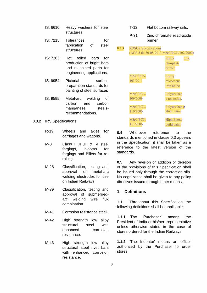
0.3.3 RDSO's Specifications (ACS-5 dt. 30-08-2013 M&C/PCN/102/2009)
Epoxy zinc phosphate primer.
M&C/PCN/103/2011
Epoxy micaceous iron oxide.
M&C/PCN/109/2009
Polyurethane red oxide.
M&C/PCN/110/2006
Polyurethan e aluminium.
M&C/PCN/111/2006
High Epoxy build paint.
0.4 Wherever reference to the
standards mentioned in clause 0.3 appears
in the Specification, it shall be taken as a
reference to the latest version of the
standards.
0.5 Any revision or addition or deletion
of the provisions of this Specification shall
be issued only through the correction slip.
No cognizance shall be given to any policy
directives issued through other means.
1. Definitions
1.1 Throughout this Specification the
following definitions shall be applicable.
1.1.1 ‘The Purchaser' means the
President of India or his/her representative
unless otherwise stated in the case of
stores ordered for the Indian Railways.
1.1.2 'The Indentor' means an officer
authorized by the Purchaser to order
stores.
4
1.1.3 'The Engineer' means the Consulting
Engineer or officer authorised by the
Purchaser to act as an Engineer.
1.1.4 'The Inspecting Officer’ means the
person, firm or department nominated by the
Purchaser to inspect the stores on his/her
behalf and the Deputies of the Inspecting
Officer so nominated.
1.1.5 ‘The Contractor’ means the person,
firm, or company with whom the order for the
supply/ fabrication/ erection is placed and
shall be deemed to include the Contractor’s
successors (approved by the Purchaser),
representatives, heirs, executors and
administrators as the case may be unless
excluded by terms of the contract.
1.1.6 ‘The Sub-Contractor’ means any
person, firm, or company from whom the
Contractor may obtain any material or
fittings to be used in the supply or
manufacture of the stores.
1.1.7 'The Exhibited Drawings' refer to the
drawings, which are exhibited or issued for
the guidance of persons tendering. The
number for each of these drawings is given
in the schedule.
1.2 The drawings, supplied by the
Contractor, as per which the fabrication is to
be executed, when approved by the
Engineer will become ‘Fabrication
Drawings’. Also on completion of the work,
the Contractor should supply ‘Completion
Drawings’ along with alterations if any.
2. Responsibility for Completeness
2.1 The Contractor shall be entirely
responsible for the execution of the contract
in all respects in accordance with the terms
of this Specification and the conditions of
contract, notwithstanding any approval
which the Engineer/Inspecting Officer may
have given to the detailed drawings
prepared by the Contractor or Sub-
Contractor for materials or other parts of
the work involved in the contract or for tests
carried out, either by the Contractor or by
the Engineer/Inspecting Officer.
2.2 Any fitting, accessory or apparatus
which may not have been mentioned in this
Specification, but which are usual or
necessary in the execution of such work,
are to be provided by the Contractor
without extra charge. The whole work must
be completed in all details, whether
mentioned in this Specification or not, with
the exception of such work as has been
specified in the Schedule of Requirements
to be separately provided for by the
Purchaser.
3. Sub-letting of Work
3.1 Before ordering sub-letting of work,
the Contractor shall submit the names of
the Sub-Contractors proposed for the
approval of the Engineer and shall
afterwards send the Inspecting Officer a
copy of the orders for the sub-letted work.
3.1.1 The Contractor shall be responsible
for all the sub-letted work. Such work shall
be inspected and verified by the Inspecting
Officer.
4. Stacking Materials
4.1.1 On receipt of materials at the bridge
yard they shall be carefully unloaded
examined for defects, checked, sorted and
stacked securely on a level bed out of
danger from flood or tide and out of contact
with water or ground moisture. All material
shall be available for inspection by the
Engineer or Inspecting Officer.
4.1.2 Materials shall be verified with the
markings shown on the marking plan of
part list, which shall be supplied by the
manufacturers or the Engineer.
5
4.1.3 Any material found damaged during
transit or while unloading should be stacked
separately and damaged portions shall be
indicated by paint with distinctive colour. All
such materials shall be dealt with under the
orders of the Engineer without delay. If any
component after receipt at site, has in the
opinion of the Engineer or Purchaser, been
damaged in transit, such component shall be
replaced or repaired to the satisfaction of the
Engineer or Purchaser free of cost.
4.1.4 All such damaged material shall be
dealt with as per the orders of the Engineer.
Badly damaged portions may require
replacement. Slightly distorted parts may be
straightened by gradual pressure without
heat or annealing. Badly distorted or broken
parts must be dealt with as the case
demands and as directed by the Engineer.
4.1.5 Where the work has been passed in
the manufacturer’s works as strictly
interchangeable, all members bearing the
same marks can be stacked together without
reference to any particular span.
4.1.6 The Contractor shall unload the
material promptly on delivery; otherwise
he/she shall be responsible for demurrage
charges.
4.1.7 On receipt of rolled steel at workshop
or fabrication yard they shall be carefully
unloaded and stacked properly to avoid
bending, twisting, corrosion etc.
5. Imported Material
5.1 In case of work fabricated in India,
where any material or component is
imported, such material or component will be
inspected, if desired by the Contractor,
Purchaser or Inspecting Officer, and passed
in the country of origin before despatch to
India. In such cases the Contractor shall
submit to the Inspecting Officer details on
prescribed form in quadruplicate of the
materials or components to be inspected
together with the requisite number
of copies of all necessary documents,
to enable inspection to be carried out prior
to despatch. The cost of such inspection
and supervision of tests in connection
therewith will be borne by the Purchaser,
the Sub-Contractor providing free of
charge all material, labour and appliances
for carrying out tests made in his/her
works and any material which may
be required for independent tests and
analysis.
6. Leading to Site
6.1 Care must be taken by
the Contractor to see that the parts at site
are available in proper sequence.
7. Lines and Levels
7.1 All lines and levels should be
given by the Engineer and all stakes and
marks so given shall be carefully preserved
by the Contractor who shall give all
necessary assistance and facilities to
establish or check the lines and levels
and to measure the work.
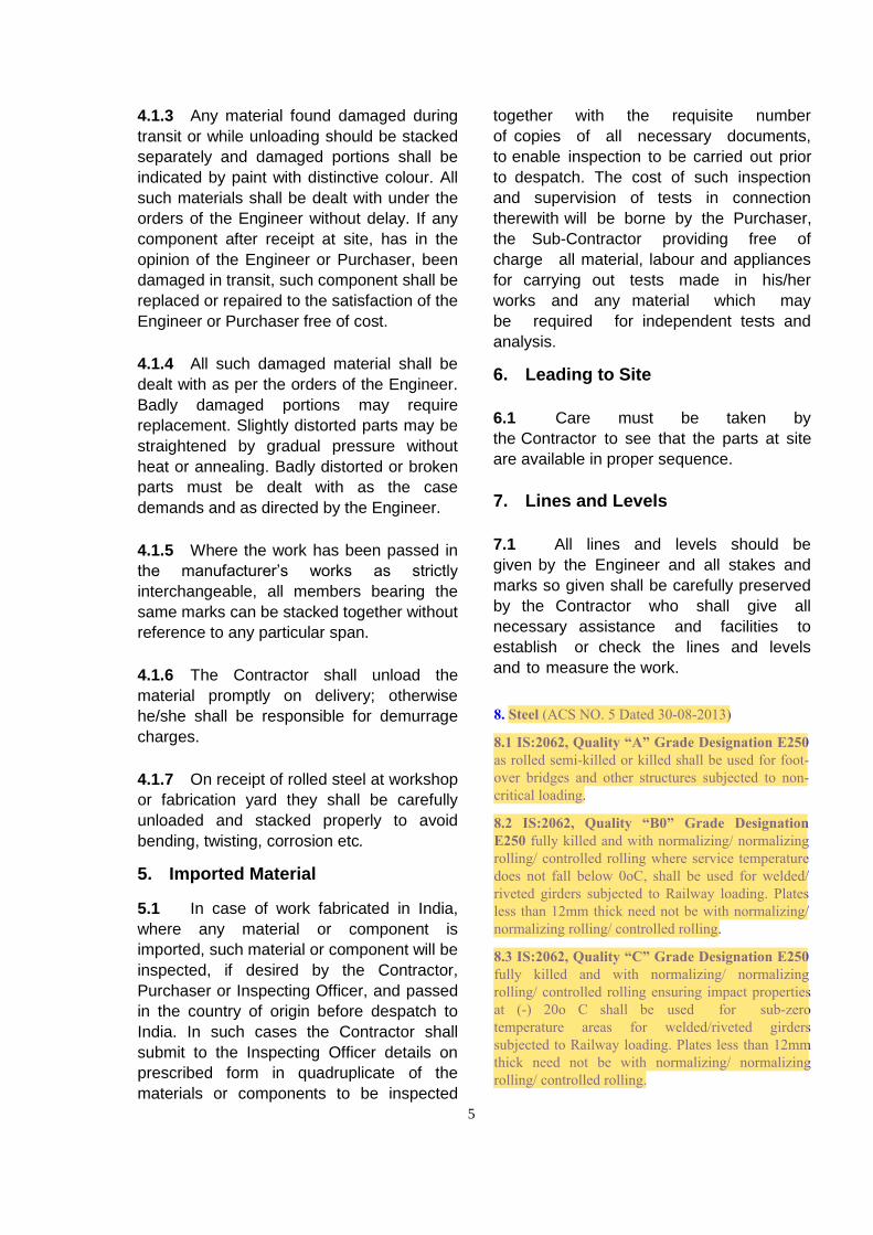
8. Steel (ACS NO. 5 Dated 30-08-2013)
8.1 IS:2062, Quality “A” Grade Designation E250 as rolled semi-killed or killed shall be used for foot-over bridges and other structures subjected to non-critical loading.
8.2 IS:2062, Quality “B0” Grade Designation E250 fully killed and with normalizing/ normalizing rolling/ controlled rolling where service temperature does not fall below 0oC, shall be used for welded/riveted girders subjected to Railway loading. Plates less than 12mm thick need not be with normalizing/ normalizing rolling/ controlled rolling.
8.3 IS:2062, Quality “C” Grade Designation E250 fully killed and with normalizing/ normalizing rolling/ controlled rolling ensuring impact properties at (-) 20o C shall be used for sub-zero temperature areas for welded/riveted girders subjected to Railway loading. Plates less than 12mm thick need not be with normalizing/ normalizing rolling/ controlled rolling.
6
8.5 For superior and enhanced corrosion
resistance for sections, plates and bars for
welded, rivetted or bolted construction, the
material shall comply with the requirement
of IRS:M-42,Gr I or Gr.II for rivetted/bolted
or welded work respectively.
8.6 Steel, which is to be cold pressed,
shall comply with the requirements of
IS:2002.
8.7 Steel for bolts shall conform to
property class 4.6 or 6.6 as specified in
IS:1367 accordingly, as the structural steel
specification is for mild steel or high tensile
steel.
8.8 Steel for drifts shall be in accordance
with IS:1875 for forged quality steel or
IS:7283 for hot rolled bars.
8.9 Steel for rivets shall comply with the
requirement of IS:1148 for hot rolled rivet
bars for general structural purposes and
IS:1149 for high tensile steel rivet bars for
high strength structural purposes. For high
strength low alloy structural steel rivet bars
with enhanced corrosion resistance for use
in bridges, steel shall comply with the
requirement of IRS:M-43.
8.10 The dimensions of all rolled
sections must agree with the contract
drawings or as agreed to between the
Purchaser and the Contractor.
8.11 The rolling and cutting tolerances
shall be in accordance with IS:1852 or as
agreed to between the Purchaser and the
Contractor if closer tolerances are desired
they shall be shown in the drawing.
8.12 All the steel sections used in the
fabrication must have mill test certificate
clearly indicating the specification to which
the steel conforms and whether steel is
killed and normalized. All the cast mark
numbers/ heat mark numbers, shall be
recorded along-with the number of plates in
a register as soon as the plates are
received in the workshop. Whenever the
steel is received without any test certificate,
a sample test piece from plate of each cast
mark number is to be cut and sent for
testing. Only when it is established that the
plates are of required specification, these
shall be processed for cutting.
8.13 Use of steel of any quality other
than those mentioned above would require
the prior approval of the Engineer.
9. Pins and Expansion Rollers
9.1 Pins and Expansion Rollers shall be
made from steel conforming to IS:2004
(Class 3 steel).
9.2 Expansion rollers may, alternatively
be turned from approved carriage and
wagon axles. Only axles manufactured
after 1931 shall be used for the
manufacture of rollers. USFD test shall be
conducted to ensure freeness from internal
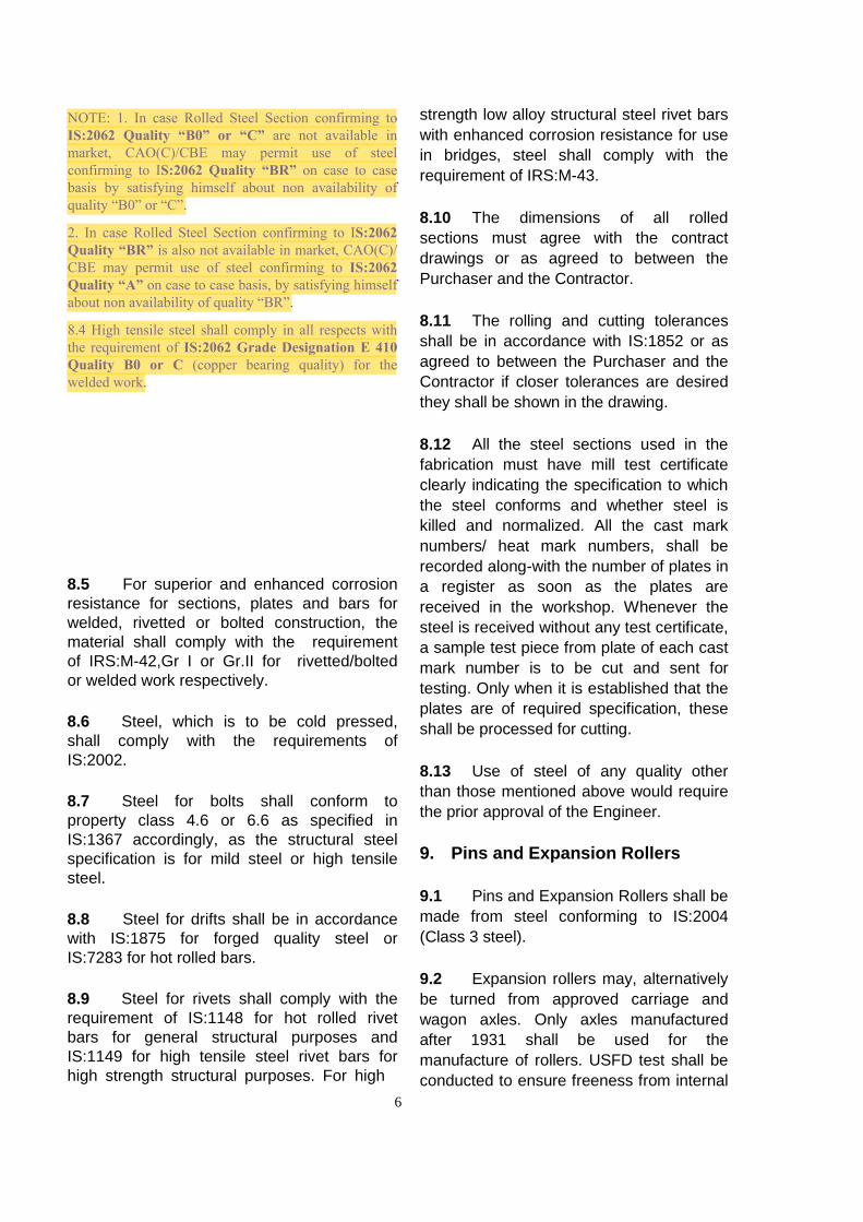
NOTE: 1. In case Rolled Steel Section confirming to IS:2062 Quality “B0” or “C” are not available in market, CAO(C)/CBE may permit use of steel confirming to IS:2062 Quality “BR” on case to case basis by satisfying himself about non availability of quality “B0” or “C”.
2. In case Rolled Steel Section confirming to IS:2062Quality “BR” is also not available in market, CAO(C)/CBE may permit use of steel confirming to IS:2062Quality “A” on case to case basis, by satisfying himselfabout non availability of quality “BR”.
8.4 High tensile steel shall comply in all respects with the requirement of IS:2062 Grade Designation E 410 Quality B0 or C (copper bearing quality) for the welded work.

7
flaw. Test pieces shall be left as an integral
part of the roller with the stamp of the
supplier on it so that the Accepting Authority
can cut-off the test pieces and check if
required.
10. Steel Castings
10.1 Steel casting shall comply with
IS:1030 for normal temperature zone and to
IS:4899 for use at low temperature zone.
11. Bronze Plates
11.1 Bronze plates shall be of phosphor
bronze complying with IS:1458 Class I.
12. Maintenance of Records by Fabricators
12.1 The records of fabrication shall be
maintained in the registers as per the
formats given in the Appendix I.
13. Manufacture
13.1 The whole work shall be
representative of the highest class of
workmanship. The greatest accuracy shall
be observed in the design, manufacture and
erection of every part of the work to ensure
that all parts will fit accurately together on
erection. For manufacture of the
components of all spans to be made strictly
interchangeable as specified in clause 33,
approved set of same jigs and assembly
fixtures shall be used. The tolerances in
manufacture shall be in accordance with as
shown in Appendix II. The Contractor shall
state which of the following alternative
methods of manufacture he/she intends to
adopt.
i) The whole of work to be erected
complete and pieces marked to place.
ii) All spans to be made strictly
interchangeable as specified in
clause 33.
13.2 The Contractor shall maintain a
master steel tape of approved make for
which he/she has obtained a certificate of
accuracy from any National Test House or
Government recognised institutions
competent to do so.
14. Templates
14.1 The templates through out the work
shall be of steel. The template shall be
used for marking of cutting material and as
well as profile machining for girders of
railway loading. Templates shall be used
for marking of drilling holes in steel
structures other than girder of Railway
loadings. In case where actual materials
from a bridge have been used as templates
for drilling similar pieces the Inspecting
Officer will decide whether they are fit to be
used as part of the finished structure.
15. Flattening and Straightening
15.1 All steel materials, plates, bars and
structural’s shall have straight edges, flat
surfaces and be free from twist. If
necessary, they shall be cold straightened
or flattened by pressure before being
worked or assembled unless they are
required to be of curvilinear form. Pressure
applied for straightening or flattening shall
be such as it would not injure the material
and adjacent surfaces or edges shall be in
close contact or at uniform distance
throughout.
15.2 Flattening and straightening under
hot condition shall not be carried out unless
authorized and approved by the Inspecting
Officer.
8
16. Planing and Shearing
16.1 Except where otherwise indicated,
cutting of all plates and sections shall be
affected by shearing or sawing. All edges
shall be clean, reasonably square and true.
Wherever possible the edges shall be cut in
a shearing machine, which will take the
whole length of the plate in one cut.
16.2 Should the inspection find it
necessary, the cut edges shall be ground
afterwards.
16.3 Planing or machining of the edges or
surface shall be carried out when so
specified in the contract drawings or where
specifically ordered by the Engineer. Where
machining is specified, the plates or all
sections shall be cut in the first instance to
such a size so as to permit not less than
3mm of metal being removed from each
sheared edge or end, in the case of plates or
sections of 12mm or less in thickness and
not less than 6mm of metal being removed
in the case of plates and sections
exceeding 12mm in thickness.
16.4 The butting ends of all booms and
struts where spliced shall be faced in an end
milling machine after members have been
completely fabricated. In the case of
compression members the face shall be
machined so that the faces are at right angle
to the axis of the members and the joint
when made, will be in close contact
throughout. At the discretion of the
Inspecting Officer, a tolerance of 0.4mm
may be permitted at isolated places on the
butting line.
17. Flame Cutting
17.1 Flame cutting by mechanically
controlled torch/torches shall be accepted
both in the case of mild steel and high
tensile steelwork. Provided the edge as
given by the torch is reasonably clean and
straight, plates may be cut to shape and
beams and other sections cut to length with
a gas cutting torch, preferably oxyacetylene
gas should be used.
17.2 All flame cut edges shall be ground
to obtain reasonably clean square and true
edges. Draglines produced by flame cut
should be removed.
17.3 Unless machining has been
specifically provided for, special care is to
be taken to ensure that ends of all plates
and members are reasonably in close
contact and the faces are at right angles to
the axis of the members and joints, when
made, are also reasonably in close contact.
17.4 Use of multi-head flame cutting
machine having multiple oxy acetylene
torches is desirable for higher productivity
and reducing the distortion due to cutting
operation. Plasma-arc cutting method can
also be employed. This process offers less
heat input causing less distortion.
18. Drilling and Sub-punching
18.1 All holes shall be drilled but the
Contractor may, if he/she so prefers sub-
punch them to a diameter 6mm less than
that of finished holes, e.g. a punched hole
which is to be drilled out to 25mm in
diameter shall not exceed 19mm in
diameter at the die end. When the rivet
holes are to be sub-punched, they shall be
marked with a centre punch and made with
a nipple punch or preferably, shall be
punched in a machine in which the position
of the hole is automatically regulated. The
punching shall be so accurate that when
the work has been put together before
drilling, a gauge 1.5mm less in diameter
than the size of the punched holes can be
passed easily through all the holes. Holes
for countersunk heads of rivets, bolts or
screws shall be drilled to the correct profile
so as to keep the heads flush with the
9
surface Holes for countersunk heads of
rivets, bolts or screws shall be drilled to the
correct profile so as to keep the heads flush
with the surface
18.2 No sub-punching shall be allowed in
the main truss members of open-web
girders.
18.3 Holes for turned bolts, should be
1mm under drilled in shop and should be
reamed at site to suit the diameter of turned
bolt.
18.4 Where the number of thicknesses to
be rivetted exceeds three or the total
thickness is 90mm or more, the rivet holes,
unless they have been drilled through steel-
bushed jigs, shall be drilled out in place
3mm all round, after assembling. In such
cases the work shall be thoroughly bolted
together.
18.5 The steel bushes shall be case
hardened by an approved process and
checked for diameter after the heat-
treatment. The bores of bushes shall initially
have a tolerance of -0mm, 0.1mm. The
tolerance shall be checked from time to time
and when the bores exceed a tolerance of, -
0mm, +0.4mm, the bushes shall be rejected.
For this purpose, go and no-go gauges are
to be used. Tolerances for checking jigs
from master plates shall be +0mm-0.13mm.
18.6 The work shall be taken apart after
drilling and all burrs left by the drill and the
sharp edges of all the rivet holes completely
removed.
19. Parts in Contact
19.1 All steel work intended to be rivetted
or bolted together shall be in contact over
the whole surface.
19.2 Drifts as shown in Fig. 2 may be
used for drawing light members into position
but their use on heavy members should be
restricted to securing them in their correct
positions. In no case, shall drifting be
allowed to such an extent that holes are
distorted.
19.3 Drifting to enlarge unfaired holes is
prohibited. The holes that will have to be
enlarged to admit rivets should be reamed
provided the Engineer permits such
reaming after satisfying himself about the
extent of inaccuracy and the effect of
reaming on the soundness of the structure.
The Purchaser retains the right to reject all
steel work if the holes are not properly
matched.
20. Making of Joints
20.1 Cleaning of permanent contact
surfaces:- Surfaces which will have
permanent contact shall be removed of
paints and mill scale down to bare metal,
clean and dried and immediately a coating
of zinc chrome red oxide priming to IS:2074
shall be applied. Care shall be taken to
see that all burrs are removed and no
surface defects exist before the parts are
assembled.
20.2 Bolting and Drifting:- Only barrel
drifts as per Fig. 2 shall be used in
erection. They may be used for drawing
light members into position; but their use
on heavy members shall be restricted to
securing them in their correct position. Any
apparent error in shop work, which
prevents the assembling and fitting up of
the parts by the proper use of these drifts,
shall be investigated immediately. As all
work is rigidly inspected in the
manufacturers work before despatch, these
difficulties should not arise and the cause
should be first be sought in the use of
incorrect components or the transposition
of a correct part. It is usually important that
parts should be correctly handled. Should
error still persist, the matter shall be
10
immediately reported to the Engineer who
will decide what action is to be taken. No
reaming shall be undertaken without the
written authority of the Engineer, except for
the under drilled holes meant for turned
bolts. If approved, the Contractor shall
supply, at his/her own expense, any special
rivets that maybe required. Copies of all
correspondence relative to the recourse to
reaming and the use of over-size rivets shall
invariably be sent by the Engineer for
information to the inspectorate concerned.
20.3 Joints shall normally be made by
filling not less than 50% of the holes with
service bolts and barrel drifts in the ratio of
four to one. The service bolts are to be fully
tightened up as soon as the joint is
assembled.
20.4 Special methods of erection other
than described in Appendix III. In
cases where the joints have to withstand
stresses arising from special method of
erection, provision is to be made to take the
whole stress that will or may occur.
Cylindrical drifts and turned bolts shall be
used to withstand such stresses and no
reliance is to be placed on the service bolts
for this purpose. Upto maximum of 40% of
the holes of each member of the joint are to
be filled with drifts and balance of strength
required is to be attained with turn bolts. The
position and number of the drifts and bolts
will be intimated by the Engineer. The
condition of clause 20.1 must be observed
and the bolt fully tightened up as soon as the
joint is made.
20.5 Where the manufacturing of girders
has been done in accordance with clause 33
relating to steel girder bridges, the erection
shall be done in accordance with Appendix
III. However, if the Contractor desires to
adopt any other method of erection, he/she
shall submit the scheme and obtain the
approval of the Engineer. It shall be ensured
that when in position, the girder has the
camber as per drawing.
20.6 Emergency Jointing:- In the event of
an emergency arising such as the staging
is in danger of being carried away by floods
before the rivetting can be completed, the
joints shall be made secure by filling 40%
of the holes with cylindrical drifts and equal
number with service bolts fully tightened .
21. Erection and Equipment
21.1 The Contractor shall provide at
his/her own cost all tools, machinery,
equipment and erection material necessary
for the expeditious execution of the work
and shall erect the structural steel and iron
work, in every respect as covered by the
contract and in accordance with the
drawings and specifications.
21.2 If any labour, material, plant staging
haulage and storage facilities are to be
provided by the Purchaser, details of such
items and the conditions under which these
are to be supplied shall be clearly specified
in the contract agreements. In the absence
of any such provisions in the agreement,
the Contractor shall make his/her own
arrangement for such items.
21.3 Before starting the work, the
Contractor shall advise the Engineer fully
as to the method he/she proposes to follow
and the amount and character of
equipment he/she proposes to use, which
shall be subjected to the approval of the
Engineer. The approval of the Engineer
shall not be considered as relieving the
Contractor of the responsibility for the
safety of his/her method or equipment or
from carrying the work in full accordance
with the drawings and specifications.
21.4 All temporary work shall be properly
designed and substantially constructed for
the loads, which it will be called upon to
11
support. Adequate allowance and provision
of a lateral forces and wind loads shall be
made according to local conditions and
ensure that support shall not settle during
erection.
21.5 Careful and periodical inspection of
plants shall be made by the Contractor to
ensure that all tackle, ropes, chains and
other important lifting gear and machinery
are in good order and fit for service and well
upto the capacity for which they are
required.
21.6 When chains are used for lashing,
care must be taken to protect the edges of
members to avoid the marking and distortion
otherwise caused.
21.7 Span erected upon staging shall be
supported upon suitable blocks, which shall
ensure that the girders shall be at the correct
elevation and alignment when completed. If
other methods of erection be adopted where
staging in situ is not employed, special
means shall be used to ensure this.
21.8 The method used for lifting and
slinging flexible members shall be brought to
the notice of the Engineer and shall be
subject to his/her approval.
21.9 Temporary bracing shall be provided
to take care of stresses from erection
equipment or other loads carried during
erection.
22. Bearings and Anchorages
22.1 Bed plates shall be set to required
level and fixed accurately in position by
giving full and even bearing by setting them
on a layer of cement sand and cast iron
chips as approved and directed by the
Engineer.
22.2 The Contractor shall drill the holes
where necessary and set the anchor bolts.
The bolts shall be set accurately and fixed
with cement grout or any other grouting
material as approved by the Engineer
completely filling the holes.
23. Rivets and Rivetting
23.1 The dimensions on the drawings
referred to the diameters of the rivet holes
and their finished rivets. The rivet holes
shall be 1.5 mm greater than the diameter
of the rivet bars used. The rivets shall be
made to IS:1929. The shanks of the
undriven rivets shall be made of a length
sufficient to fill the holes thoroughly and
form the head. The clearance i.e. the
difference in diameter between the rivets
measured under head before being heated
and the rivet hole shall not be less than
0.75mm. Before riveting is commenced, all
works shall be properly bolted so that the
sections rivetted are in close contact
throughout. Rivets shall completely fill the
holes and shall be machine driven by
means of pressure or percussion rivetters
of approved design.
23.2 All rivets shall be properly heated to
straw heat for the full length of the shank,
firmly backed and closed. The head of the
rivet, particularly in long rivets, shall be
heated more than the point and in no case
shall the point be heated, more than the
head. Sparking or burnt rivets shall not be
used. Where it is impossible to back up by
normal method of holding up, ‘double
gunning’ may be resorted to. Alternatively
pneumatic holding device may be used.
23.3 Gauges for rivet dimensions and
contours shall be provided by the
Contractor for the use of the Inspecting
Officer.
23.4 Rivets when driven shall completely
fill the holes, have the heads concentric
with the shanks and shall be in full contact
with the surface. Driven rivets when struck
12
sharply on the head with the 110-gm. rivet
testing hammer, shall be free from
movement or vibration.
23.5 While rivetting built-up members
great care should be exercised to ensure
that the set of holes for field rivets in each
flange of the built-up member, is aligned
dead-square in relation to that in the other
flange and not ‘aborrated’. Use of assembly
fixtures shall be made to ensure this.
23.6 All loose and burnt rivets and rivets
with cracks badly formed, eccentric or
deficient heads shall be cut out and
replaced. Permissible deviation of driven
rivets shall be as per Appendix IV. Rivets
shall also be cut out when required for the
examination of the work. Actual method of
cutting out shall be approved by the
Engineer. Recupping and caulking shall in
no circumstances be resorted to.
23.7 Rivetting shall not be started until
such time as the Engineer has personally
satisfied himself that the alignment of the
girders is correct, the verticals plumb
laterally, the camber according to that shown
on the camber diagram with camber jacks
screwed tight, all the joints and cover plates
well up, service bolts tight and field rivet
holes coinciding. Special care should be
taken that service bolts are frequently re-
tightened as the rivetting proceeds.
23.8 All field rivets shall be tested as
directed by the Engineer.
23.9 Where practicable all rivetting shall
be done by pneumatic or hydraulic rivetting
machine. The working pressure to be
employed when using pneumatic or
hydraulic tools shall be approved by the
Engineer. Hand rivetting shall only be done
when sanctioned by the Engineer. In such
cases, means shall be adopted to ensure
the rivets being used in their entire length so
as to fill the rivet holes completely, the snap
being used only to give the correct form of
head.
23.10 When all the rivets of joints have
been finally passed, they shall be painted
as under.
a) one coat of ready mixed zinc
chrome primer to IS:104
followed by one coat of ready
mixed paint red oxide zinc
chrome primer to IS:2074
b) Finishing coat as per clause 39
24. Field Rivets, Bolts, Nuts andService Accessories
24.1 The work is to include supply of all
units, bolts, nuts, washers etc. required to
complete erection at site with an allowance
for wastage etc. of 12.5% of the net
number of field rivets, bolts and washers
required subject to a minimum number of
five in each item.
24.2 The Contractor shall be responsible
for supplying site rivets of approved length.
The length of such rivets shall be verified
by snapping a few rivets of each length in
the presence of the Inspecting Officer. In
the case of rivets with long grips (with grip
exceeding 6 times the diameter) specimen
rivets on the test piece shall be cut to see if
the holes are totally filled even though the
rivets are tight under the usual hammer
tests.
24.3 Black hexagonal bolts (Service
bolts) with nuts and ordinary platter’s
washers and drifts for use in the erection of
the work shall also be supplied at 60%
(45% bolts and 15% drifts) of the number of
field rivets per span in each size (this
includes wastage). The Purchaser may
however, specify a reduction in the
quantities of service bolts etc. if more than
one span of each type is ordered.
13
25. Smithed Work
25.1 All joggles shall be performed by
pressure. Craned sections or knees can be
formed by forging or by gas cutting and
welding by any approved electric arc
process. Any bending, forging, cutting or
welding shall be carried out in such a
manner as not to impair the strength in the
metal. Forging shall be annealed as
indicated in the drawing.
25.2 If drop forging through dies is
resorted to, excessive forging in one
operation shall be avoided. Where
necessary, a series of intermediate stage
dies shall be manufactured and used.
26. Welding
26.1 Welded construction work shall be
carried out generally in accordance with the
provisions of Indian Railway Standard
Welded Bridge Code and subject to further
specifications given in the following
paragraphs.
26.2 All welds should be done by
submerged-arc welding process either fully
automatic or semi-automatic. Carbon di
oxide welding or manual metal-arc welding
may be done only for welds of very short
runs or of minor importance or where access
of the locations of weld do not permit
automatic or semi-automatic welding.
26.3 Except for special types of edge
preparation, such as single and double ‘U’
single and double ‘J’ the fusion edges of all
the plates which are to be joined by welding
may be prepared by using mechanically
controlled automatic flame cutting equipment
and then ground to a smooth finish. Special
edge preparation should be made by
machining or gouging.
26.4 Welding procedures:- The welding
procedure shall be such as to avoid
distortion and minimise residual shrinkage
stresses. Properly designed jigs should be
used for assembly. The welding techniques
and sequence, quality, size of electrodes,
voltage and current required shall be as
prescribed by manufacturers of the material
and welding equipment. The Contractor
should submit full details of welding
procedure in proforma given at Apppendix
V.
26.5 Site welding should not be
undertaken except in special
circumstances with the approval of the
Chief Bridge Engineer. Site welding should
be confined to connections having low
stresses, secondary members, bracings
etc.
26.6 Manual metal arc welding may be
done taking adequate precautions as per
IS:9595 and under strict supervision.
27. Sequence of Welding and WeldPass
27.1 For fabrication of welded composite
girders, channel shear connectors shall be
welded on top flange plate prior to
assembly of I-section. This facilitates
correction of any distortion of flange plate
developed during the welding of channel
shear connectors.
27.2 In making a typical I-section four
fillet welds are to be made. The welding
sequence to be followed is indicated by
number 1 to 4 as shown in the Fig. 3.
27.3 Whenever a square butt weld in a
10 or 12mm thick plate is required to be
made, the sequence to be adopted is
shown in Fig. 3.
14
28. Bolts, Nuts and Washers
28.1 Bolts, Nuts and Washers shall be in
accordance with the following
specifications:-
(i) Black hexagonal bolts to IS:6639
and Nuts to IS:1363.
(ii) Precision and turned bolts with
nuts and hexagonal screws to
IS:1364.
(iii) Plain washers to IS:2016 and
IS:5369.
(iv) Spring washers - IS:3063.
(v) Taper washers - IS:5372 and
IS:5374.
28.2 Manufacture, workmanship, Marking,
Packing etc. for Bolts and Nuts shall comply
with the requirements of IS:1367.
28.3 Where the head and nuts bear on
timber, square washers having the length of
each side not less than three diameters of
the bolt and the thickness not less than one
quarter of the diameter shall be provided.
Steel, wrought iron or malleable cast iron
taper washers shall also be provided for al
heads and nuts bearing on bevelled
surfaces.
28.4 For black bolts a clearance
(difference in diameter) of 1.5mm for all
sizes of bolts shall be allowed.
28.5 Where turned bolts are required they
shall be carefully turned and shall be parallel
throughout the barrel. Holes for turned bolts
should be 1mm underdrilled in shop and
should be reamed at site to suit the diameter
of the turned bolts.
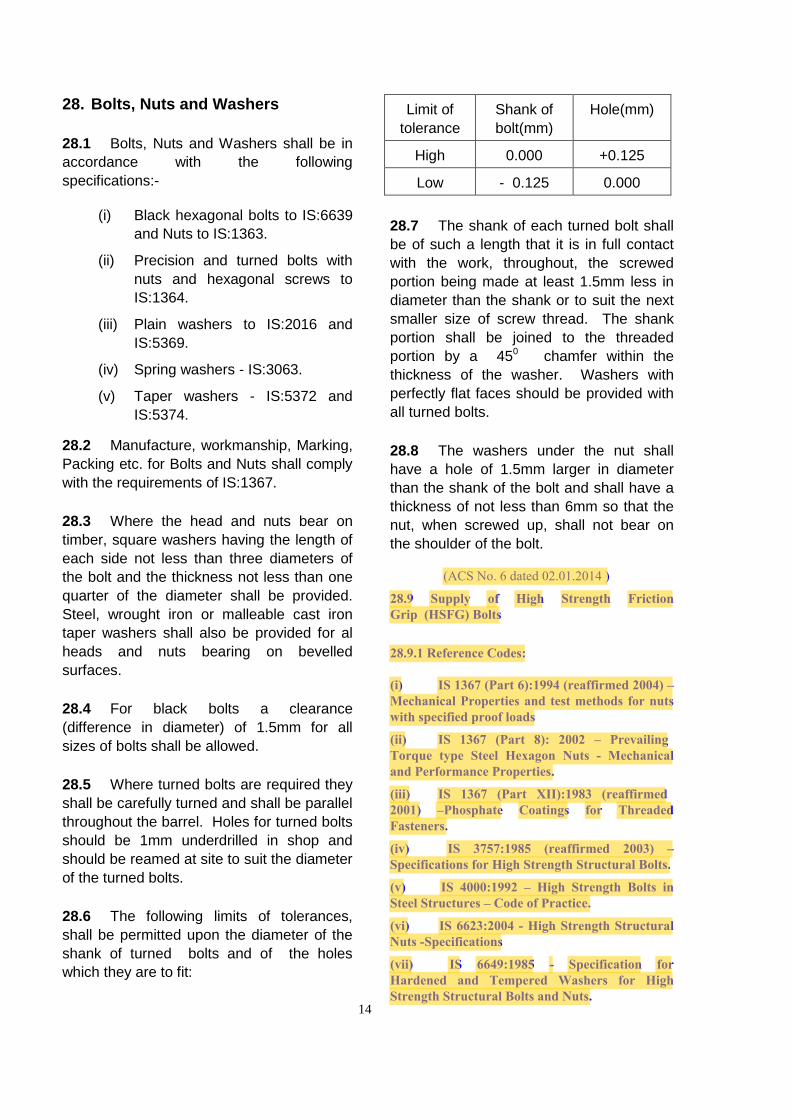
28.6 The following limits of tolerances,
shall be permitted upon the diameter of the
shank of turned bolts and of the holes
which they are to fit:
Limit of
tolerance
Shank of
bolt(mm)
Hole(mm)
High 0.000 +0.125
Low - 0.125 0.000
28.7 The shank of each turned bolt shall
be of such a length that it is in full contact
with the work, throughout, the screwed
portion being made at least 1.5mm less in
diameter than the shank or to suit the next
smaller size of screw thread. The shank
portion shall be joined to the threaded
portion by a 450 chamfer within the
thickness of the washer. Washers with
perfectly flat faces should be provided with
all turned bolts.
28.8 The washers under the nut shall
have a hole of 1.5mm larger in diameter
than the shank of the bolt and shall have a
thickness of not less than 6mm so that the
nut, when screwed up, shall not bear on
the shoulder of the bolt.
(ACS No. 6 dated 02.01.2014 )
28.9 Supply of High Strength Friction Grip (HSFG) Bolts
28.9.1 Reference Codes:
(i) IS 1367 (Part 6):1994 (reaffirmed 2004) –Mechanical Properties and test methods for nuts with specified proof loads
(ii) IS 1367 (Part 8): 2002 – Prevailing Torque type Steel Hexagon Nuts - Mechanical and Performance Properties.
(iii) IS 1367 (Part XII):1983 (reaffirmed 2001) –Phosphate Coatings for ThreadedFasteners.
(iv) IS 3757:1985 (reaffirmed 2003) –Specifications for High Strength Structural Bolts.
(v) IS 4000:1992 – High Strength Bolts inSteel Structures – Code of Practice.
(vi) IS 6623:2004 - High Strength StructuralNuts -Specifications
(vii) IS 6649:1985 - Specification forHardened and Tempered Washers for HighStrength Structural Bolts and Nuts.
28.9.2 Hierarchy of Codes: The hierarchy of codes shall be as follows:
(i) Provisions of IRS codes.
(ii) Where IRS codes are silent, relevant IS codes.
(iii) Where both IRS and IS codes are silent,relevant EN codes.
28.9.3 Definition: HSFG bolts are high strength structural bolts which have been tightened such as to induce predefined tension in the bolt shank. Provisions in this code apply to non – galvanized Bolts of dia. M12 to M36 only.
28.9.4 Types of Bolts: For the purpose of HSFG connections, only high strength structural bolts of two property classes: 8.8 and 10.9 can be used. Bolts shall conform to IS 3757. The bolts shall have the following characteristics:
(i) Identification: The property class of bolts(8.8 or 10.9) shall be embossed or indentedas 8S or 10S respectively on the top of headalong with the manufacturer’s identificationsymbol. Alternately, marking ‘8.8 S’ or‘10.9 S’ are also acceptable. The suffix ‘S’here denotes that the bolt is high strengthstructural bolt with a large series hexagon.
(ii) Length: The the length of bolt shall bechosen such as to hold the steel members inposition, with provision for the nut, washer(s)and some projection beyond the bolt. Alongwith the overall length of the bolt, the threadlength has to be specified. At least 4 fullthreads shall remain clear between thebearing surface of the nut and unthreaded partof the shank. (ACS No. 10 Dt. 22.03.2016)
(iii) The minimum length of bolt shall be workedout on the basis of maximum grip length(covering by thicknesses and all washers)minus one standard washer plus an additionalallowance as per table 1 of IS: 4000. (ACSNo. 10 Dt. 22.03.2016)
28.9.5 Nut: Each bolt shall be tightened using a high strength nut, conforming to IS 6623. The nut has to be strong enough to be able to impart the necessary torque to the bolt and also withstand the force during the life of the structure. Further, the threads in nut shall be matching with the threads in the HSFG bolt and the nut shall be free running on the threads of the HSFG bolts. Nuts shall have following characteristics:
(i) Property Class: For HSFG bolts,the property classes to be used are 8 and10 as specified in IS 1367 (Part 6), suitable forbolts of property class 8.8 and 10.9respectively. Normal height of nut shall be morethan 0.8 times the nominal bolt diameter.
(ii) Identification of Nut: The nuts havethe following markings:
(a) Manufacturer’s identification symbol.
(b) Property class, marked as ‘8S’ or ‘10S’.(The suffix ‘S’ denotes a high strengthstructural nut with a large series hexagon.)Alternately, ‘8.8 S’ or ‘10.9 S’ are also acceptable.The marking shall be either on the top or thebottom face of double chamfered nuts and shallbe either indented or embossed on nonbearingsurfaceof washer faced nuts.
28.9.5 Nut: Each bolt shall be tightened using a high strength nut, conforming to IS 6623. The nut has to be strong enough to be able to impart the necessary torque to the bolt and also withstand the force during the life of the structure. Further, the threads in nut shall be matching with the threads in the HSFG bolt and the nut shall be free running on the threads of the HSFG bolts. Nuts shall have following characteristics:
(iv) Maximum grip length of all plies,including packings and packing washers, shall notexceed 10 times the nominal diameter of the bolt.
(v) Surface Finish: All bolts shall be suppliedwith coating consisting of zinc phosphate that isused in conjunction with suitable oil of rustpreventive type as per IS 1367 (Part XII).
14/1
(i) Property Class: For HSFG bolts, the property classes to be used are 8 and 10 as specified in IS 1367 (Part 6), suitable for bolts of property class 8.8 and 10.9 respectively. Normal height of nut shall be more than 0.8 times the nominal bolt diameter.
(ii) Identification of Nut: The nutshave the following markings:
(iii) Manufacturer’s identification symbol.
(iv) Property class, marked as ‘8S’ or‘10S’.(The suffix ‘S’ denotes a high strengthstructural nut with a large series hexagon.) Alternately, ‘8.8 S’ or ‘10.9 S’ are also acceptable. The marking shall be either on the top or the bottom face of double chamfered nuts and shall be either indented or embossed on nonbearing surfaceof washer faced nuts.
(a) Manufacturer’s identification symbol.
(b) Property class, marked as ‘8S’ or ‘10S’.(The suffix ‘S’ denotes a high strength structuralnut with a large series hexagon.) Alternately, ‘8.8 S’or ‘10.9 S’ are also acceptable. The marking shallbe either on the top or the bottom face of doublechamfered nuts and shall be either indentedor embossed on nonbearing surfaceof washer facednuts.
(a) Manufacturer’s identification symbol.
(b) Property class, marked as ‘8S’ or ‘10S’.(The suffix ‘S’ denotes a high strengthstructural nut with a large series hexagon.)Alternately, ‘8.8 S’ or ‘10.9 S’ are alsoacceptable. The marking shall be either onthe top or the bottom face of doublechamfered nuts and shall be either indented orembossed on nonbearing surfaceof washerfaced nuts.
(iii) Surface of Nut: All nuts shall besupplied with coating consisting of zincphosphate that is used in conjunction withsuitable oil of rust preventive type as perIS:1367 (Part XII).
(iv) Position of nut in bolt: Nuts shall be providedin bolts preferably as follows:
(a) In girder web: Towards outside of the girder.
(b) In flanges: Towards bottom (Except when incomposite construction).
(c) In composite construction: Towards inside ofconcrete.
(d) In bracing: Towards the rolled section side sothat the space for rotation of the nut is notreadily available.
(e) Where Tapered washer is used, the nut shallpreferably be on the other side.
28.9.6 Washer: Annular rings which are provided between the bolt head/ nut and the members being joined are called washers. Washers for HSFG bolts shall conform to IS 6649. The washers have the following characteristics:
(i) Types: Three types of washers have been specifiedin IS 6649, clause 2:
a) Type A: Plain hole circular washers.
b) Type B: Square taper washers for use with
channels (60 taper)c) Type C: Square taper washers for use with I-beams
(80 taper)
Identification: Type A washers shall be identified by provision of two nibs (small projections) and manufacturer’s identification symbol in indented character. The type B and C washers shall be identified by the type identification symbol, B or C and the manufacturer’s identification symbol.
14/2
(ii)Categories of washers:
a) Plain washer: Plain washers are used as per provisions of clause 28.10.2 where other types of washersare not suitable. HSFG bolts shall be provided with minimum one washer.
b) Packing washers: If the bolt is longer than required, plain washers may be used as packing washers also.However, the maximum number of packing washers shall be limited to 3, with maximum totalcombined thickness of 12 mm.
c) Tapered Washer: Where the angle between the axis of bolt and the joint surface is more than 3degree off normal, a tapered washer shall be used against the tapered surface. Non rotating surfaceshall preferably be placed against tapered washer.
d) Direct Tension Indicators (DTI): The Direct Tension Indicators are special type of washers withprojections which get pressed when tension is applied. The pressing of projections to required levelindicates that the required tension
has been applied in the bolts. DTIs have multiple projections, between which the feeler gauge is to be inserted to check if the bolt has been sufficiently tightened or not. The projections shall be kept in the direction of nut/head of bolt and not towards member.
(iii) Calibration of Direct Tension Indicator: Before the DTI are brought to site, the same shall be tested in thepresence of engineer. Three nos. bolts of similar diameter and property class as to be used in the workshall be taken and installed with DTI. The installation procedure to be followed shall be similar to the one givenfor plain washers. On full tightening, the projections on DTI washers shall meet the requirements ofchecks specified after second stage tightening using DTIs. Alternately, calibrated load cells may be used tocheck the calibration of DTI washer. Only the DTIs which satisfy the calibration shall be brought to sitefor work.
(iv) Surface Finish: All washers (except Direct Tension Indicators i.e. DTIs which may have anysurface finish, as specified by manufacturer, with condition that the surface finish shall be compatible withthe metallurgy of the steel structure and the HSFG bolt/ nut) shall be supplied with coating consistingof zinc phosphate that is used in conjunction with suitable oil of rust preventive type as per IS 1367 (Part XII).
28.10 Fabrication and Assembly of High Strength Friction Grip (HSFG) Bolts
28.10.1 Holes for HSFG Bolts: Normal holes in the steel members being connected by the rivets shall be used for HSFG bolts also, subject to the following:
(a) Making of holes: The holes shall be made by drilling only.
(b) Nominal Diameter of Hole: The nominal diameter of hole shall be 1.5 mm more than the boltdiameter for less than 25mm bolt and 2mm more than the nominal diameter of the HSFG bolt for largerdiameters.
(c) Oversize Holes: In case the bolts are to be provided in existing structure, the maximum size of holeshall not exceed 1.25 d or d + 4 mm whichever is less.
14/3
28.10.2 Number of washers and their fixing:
(i) DTIs are very good method of ensuring that the bolts are tightened properly, and this method oftightening shall be preferred over the method with plain washers. Hence DTI washers shall bepreferably used. If there is some problem with availability of DTIs, plain washers may be used forinstallation of HSFG bolts after approval of SAG officer in-charge of the work.
(ii)The DTIs used shall be the ones which are compatible metallurgically and also suitable for the bolts ofproperty class 8.8 and 10.9. Suitable markings identifying the bolt manufacturer, property class of DTI and itsdiameter shall be engraved suitably on the DTI.
(iii) Number of washers to be provided:
(a)Two washers shall be provided, one against head and one against the nut.
(b)One DTI shall be used in one bolt. In case DTI is being provided, the same will count as one washeri.e.,one DTI and one plain washer shall be provided.
(c)DTIs shall normally be provided below the head of the bolt (with projections towards bolt head) incase nut is rotated. In case the bolt is to be rotated, DTI shall normally be provided under nut (withprojections towards nut). In case other side is not accessible for measuring projection gap in DTI, the DTImay be provided under nut which is being rotated. In this case, an additional washer shall be provided on theDTI side to protect the projections from damage due to the abrasion during bolt tightening.
28.10.3 Surface preparation for steel interface before providing HSFG bolts: The steel interface between the plies which form a joint having HSFG bolts shall have special surface preparation so that sufficient slip factor is available. The surface preparation shall be as assumed by designer in design, based on slip factor specified in Table XIII of Steel Bridge Code. The following surface preparation are recommended:
(i). New construction: The interface between the plies which are connected together by the HSFG bolts shall be “Aluminium metallised without any over coating”. The aluminium metallising shall be as per para 39.2.1 (ii). Existing structures: The interface of plies which are to be included in the HSFG bolts shall be cleaned by wire brushing/ flame cleaning equivalent to the surface specified in IRBM para 217, 1 (b), (i) to (iv). The surfaces shall be cleaned to remove all loose rust and paint layers (Only isolated patches of coatings/ rust can remain). If, however, in existing structures, rivets are to be replaced by bolts but no surface preparation is possible, the slip factor shall be suitably reduced as per Table XIII of Steel Bridge Code.
28.10.4 Personnel For Tightening: The tightening of HSFG bolts is a technical procedure. Only trained personnel who understand the procedure shall carry out the installation of HSFG bolts. Before any person is deployed for installation, his knowledge of the procedure for tightening shall be checked and if found satisfactory, a competency certificate shall be issued by an engineer not below the rank of ADEN or equivalent. The competency certificate once issued shall be valid for six months. Any person deployed for installation of HSFG bolts must possess a valid competency certificate.
28.10.5 Procedure for tightening: Bolts shall be tightened so as to impart bolt tension as specified in para 7.12.6 of IRS Code Of Practice For The Design Of Steel Or Wrought Iron Bridges carrying Rail, Road Or Pedestrian Traffic. The following steps shall be followed for tightening of bolts:
(i) The holes shall be brought in alignment by using drifts etc. such that the bolt threads are notdamaged during insertion of bolts. Drifting shall not distort the metal or enlarge the holes.
(ii) The member being joined shall be held in position by insertion of few HSFG bolts (tightened to first stage (asdefined in para 28.10.6 and 28.10.7) only. These bolts shall not be tightened to second stage as defined in para28.10.6 and 20.10.7 till all the bolts in a joint are inserted and tightened to first stage. (ACS No. 9 Dt.16-01-2015).
(iii) After the alignment/ geometry of members is verified to be correct as per drawings, balancebolts shall be inserted and tightened upto first stage of tightening. The drifts inserted as aboveshall also be replaced by HSFG bolts one by one.
(iv) Clearance between plies: The final tightening shall not proceed until the gap between the plates hasbeen closed. Residual gap, if any, shall be less than 2 mm at edges. There shall, however, be no gap inthe central portion. In case the central portion is not in close contact or gap at edges is more than2 mm, straightening of members may be done after opening out the bolts inserted and the entire procedurei) to iii) above shall be repeated.
(v) Sequence of tightening: During tightening of bolts also, the steel members can continue to deform andhence the tightening of subsequent bolts can lead to loosening of already tightened bolts. In order tominimize the loosening of already tight bolts, tightening in the two stages shall be done starting from thestiffest part to the free edges. Stiffest parts of joint are generally towards the center of the joint.
14/4
28.10.6 Procedure for Installation of HSFG Bolts Using Direct Tension Indicator: The tightening is done in two stages so that the bolts already tightened do not get loose when the subsequent bolts are tightened. The procedure shall be as follows:
(a) First Stage of Tightening: As a first stage, all bolts in the joint shall be tightened to ‘snug tight’ conditionin proper sequence for tightening. Snug tight condition means the nut is tightened using an ordinarywrench by an average worker, applying maximum force on the wrench. This stage is required to bring theplies in close contact.
(b) Checks after First stage tightening: After first stage of tightening, the joint shall be checked to see if theplies are in close contact and the clearances are not exceeded.
(c) Second Stage of Tightening: During the second stage of tightening, torque wrench is used to tightenthe bolts until the indentations on the DTI indicate full tightening. The bolts shall be tightened in propersequence of tightening.
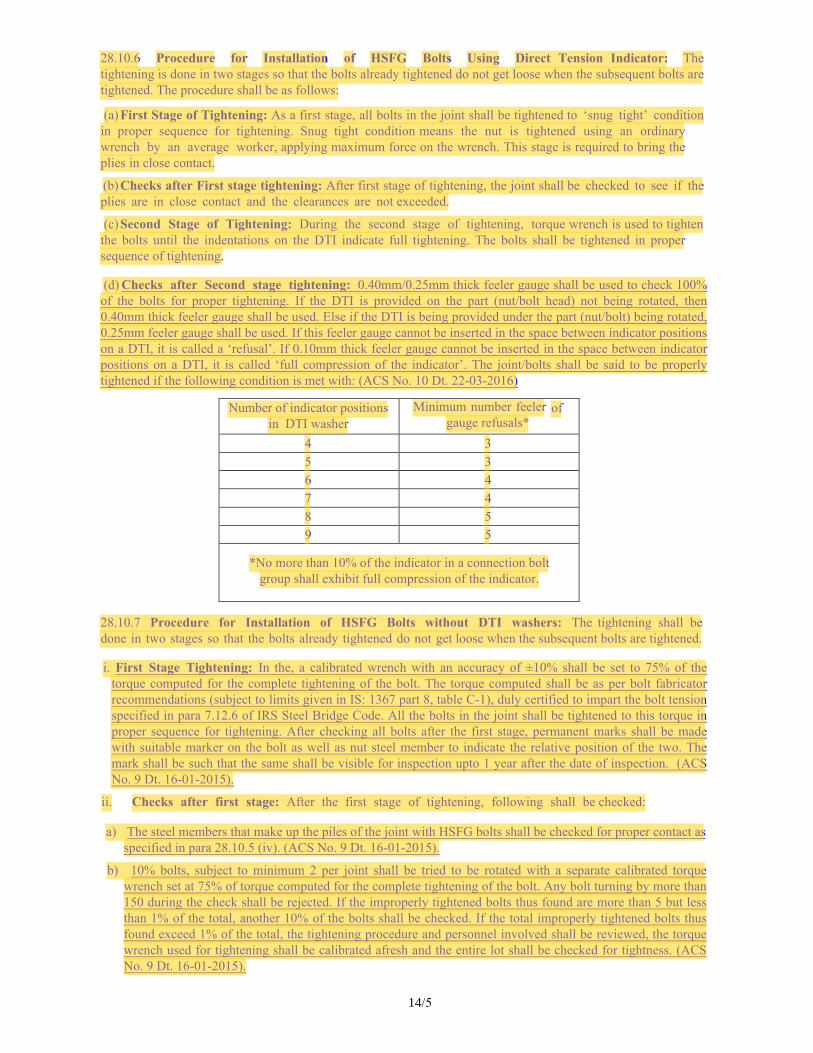
(d) Checks after Second stage tightening: 0.40mm/0.25mm thick feeler gauge shall be used to check 100%of the bolts for proper tightening. If the DTI is provided on the part (nut/bolt head) not being rotated, then0.40mm thick feeler gauge shall be used. Else if the DTI is being provided under the part (nut/bolt) being rotated,0.25mm feeler gauge shall be used. If this feeler gauge cannot be inserted in the space between indicator positionson a DTI, it is called a ‘refusal’. If 0.10mm thick feeler gauge cannot be inserted in the space between indicatorpositions on a DTI, it is called ‘full compression of the indicator’. The joint/bolts shall be said to be properlytightened if the following condition is met with: (ACS No. 10 Dt. 22-03-2016)
Number of indicator positions in DTI washer
Minimum number feeler of gauge refusals*
4 3 5 3 6 4 7 4 8 5 9 5
*No more than 10% of the indicator in a connection boltgroup shall exhibit full compression of the indicator.
28.10.7 Procedure for Installation of HSFG Bolts without DTI washers: The tightening shall be done in two stages so that the bolts already tightened do not get loose when the subsequent bolts are tightened.
i. First Stage Tightening: In the, a calibrated wrench with an accuracy of ±10% shall be set to 75% of thetorque computed for the complete tightening of the bolt. The torque computed shall be as per bolt fabricatorrecommendations (subject to limits given in IS: 1367 part 8, table C-1), duly certified to impart the bolt tensionspecified in para 7.12.6 of IRS Steel Bridge Code. All the bolts in the joint shall be tightened to this torque inproper sequence for tightening. After checking all bolts after the first stage, permanent marks shall be madewith suitable marker on the bolt as well as nut steel member to indicate the relative position of the two. Themark shall be such that the same shall be visible for inspection upto 1 year after the date of inspection. (ACSNo. 9 Dt. 16-01-2015).
ii. Checks after first stage: After the first stage of tightening, following shall be checked:
a) The steel members that make up the piles of the joint with HSFG bolts shall be checked for proper contact asspecified in para 28.10.5 (iv). (ACS No. 9 Dt. 16-01-2015).
b) 10% bolts, subject to minimum 2 per joint shall be tried to be rotated with a separate calibrated torquewrench set at 75% of torque computed for the complete tightening of the bolt. Any bolt turning by more than150 during the check shall be rejected. If the improperly tightened bolts thus found are more than 5 but lessthan 1% of the total, another 10% of the bolts shall be checked. If the total improperly tightened bolts thusfound exceed 1% of the total, the tightening procedure and personnel involved shall be reviewed, the torquewrench used for tightening shall be calibrated afresh and the entire lot shall be checked for tightness. (ACSNo. 9 Dt. 16-01-2015).
14/5
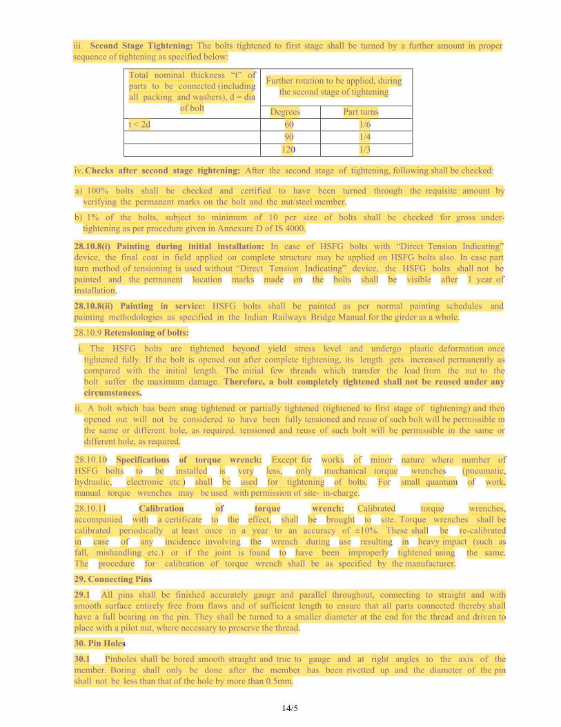
iii. Second Stage Tightening: The bolts tightened to first stage shall be turned by a further amount in propersequence of tightening as specified below:
Total nominal thickness “t” of parts to be connected (including all packing and washers), d = dia
of bolt
Further rotation to be applied, during the second stage of tightening
Degrees Part turns t < 2d 60 1/6
90 1/4 120 1/3
iv. Checks after second stage tightening: After the second stage of tightening, following shall be checked:
a) 100% bolts shall be checked and certified to have been turned through the requisite amount byverifying the permanent marks on the bolt and the nut/steel member.
b) 1% of the bolts, subject to minimum of 10 per size of bolts shall be checked for gross under-tightening as per procedure given in Annexure D of IS 4000.
28.10.8(i) Painting during initial installation: In case of HSFG bolts with “Direct Tension Indicating” device, the final coat in field applied on complete structure may be applied on HSFG bolts also. In case part turn method of tensioning is used without “Direct Tension Indicating” device, the HSFG bolts shall not be painted and the permanent location marks made on the bolts shall be visible after 1 year of installation.
28.10.8(ii) Painting in service: HSFG bolts shall be painted as per normal painting schedules and painting methodologies as specified in the Indian Railways Bridge Manual for the girder as a whole.
28.10.9 Retensioning of bolts:
i. The HSFG bolts are tightened beyond yield stress level and undergo plastic deformation oncetightened fully. If the bolt is opened out after complete tightening, its length gets increased permanently ascompared with the initial length. The initial few threads which transfer the load from the nut to thebolt suffer the maximum damage. Therefore, a bolt completely tightened shall not be reused under anycircumstances.
ii. A bolt which has been snug tightened or partially tightened (tightened to first stage of tightening) and thenopened out will not be considered to have been fully tensioned and reuse of such bolt will be permissible inthe same or different hole, as required. tensioned and reuse of such bolt will be permissible in the same ordifferent hole, as required.
28.10.10 Specifications of torque wrench: Except for works of minor nature where number of HSFG bolts to be installed is very less, only mechanical torque wrenches (pneumatic, hydraulic, electronic etc.) shall be used for tightening of bolts. For small quantum of work, manual torque wrenches may be used with permission of site- in-charge.
28.10.11 Calibration of torque wrench: Calibrated torque wrenches, accompanied with a certificate to the effect, shall be brought to site. Torque wrenches shall be calibrated periodically at least once in a year to an accuracy of ±10%. These shall be re-calibrated in case of any incidence involving the wrench during use resulting in heavy impact (such as fall, mishandling etc.) or if the joint is found to have been improperly tightened using the same. The procedure for· calibration of torque wrench shall be as specified by the manufacturer.
29. Connecting Pins
29.1 All pins shall be finished accurately gauge and parallel throughout, connecting to straight and with smooth surface entirely free from flaws and of sufficient length to ensure that all parts connected thereby shall have a full bearing on the pin. They shall be turned to a smaller diameter at the end for the thread and driven to place with a pilot nut, where necessary to preserve the thread.
30. Pin Holes
30.1 Pinholes shall be bored smooth straight and true to gauge and at right angles to the axis of the member. Boring shall only be done after the member has been rivetted up and the diameter of the pin shall not be less than that of the hole by more than 0.5mm.
14/5
15
31. Bearing and Expansion Gear
31.1 All steel bed and bearing plates or
plates over saddle castings, shall be made
perfectly level and all rivet heads on their
bearing surfaces shall countersunk and
dressed flush.
31.2 The saddles, knuckle-bearers and
roller bed-plates shall be planed on all
bearing surfaces and elsewhere as indicated
on the Contract Drawings and all bolt-holes
shall be drilled. The bottom edge of ribs
should be machined and welded to the
bottom slabs after which the top edges of
the ribs should be machined as a whole and
the top plate welded. Subsequently the top
and bottom surfaces should be machined to
the specified tolerances as given in
Appendix VI. Generally in connection with
the bearing gear all meeting surfaces
including the sides of the roller frames, shall
be machined, all bolts except anchor bolts
turned and fitted, all washers faced, the
rollers knuckles and pins polished to smooth
surface and the whole finished in the style of
first class machined work.
31.3 Tolerances shall be as specified in
Appendix VI and shall be shown on the
drawings.
32. Erection in Contractor’s Works
32.1 The work shall be temporarily
erected complete at the Contractor’s Works
for inspection by the Inspecting Officer, with
the exception of such rivetting as has to be
done at site, so that accuracy of fit and
perfection of workmanship may be assured.
The work shall be put together with sufficient
numbers of parallel drifts or turned bolts or
both to bring the pieces into place. When so
erected all holes left to be filled at site shall
be so fair that a parallel gauge turned to a
diameter 0.8mm less than that of the hole, of
a length equal to the depth of the hole, can
be passed through them without difficulty.
No drift shall be used anywhere in the work
larger in any part than the hole in which it is
to be driven. Holes for turned bolts, which
have been 1 mm underdrilled in shop,
should be reamed at site by the erecting
agency.
33. Interchangeability
33.1 Every span is to be temporarily
erected complete in Contractor’s works
adopting the method of giving camber as
explained in clause 34 and all parts as
marked to their place, unless the whole of
the work is made completely
interchangeable by the use of steel jigs and
hard steel bushes controlled by master
gauges, in which case the first span must
be completely erected to test the accuracy
of the templates. Further spans or part
span assemblies built from parts selected
at random by the Inspecting Officer shall be
erected from time to time to check the
accuracy of the work as the Inspecting
Officer may require.
33.2 If the work is considered
interchangeable by the Inspecting Officer a
simplified scheme of marking will be
permitted, i.e. all pieces which are identical
shall bear one distinguishing mark
irrespective of the span to which they
belong. Should the interchangeability not to
the satisfaction of the Inspecting Officer,
the whole of the spans must be erected
complete and all parts marked to their
place without additional charge. The
tenderers must state in their tenders
whether they intend to adopt complete
interchangeability or not.
33.3 Under special arrangement with the
Purchaser, it shall be permissible for
approved portions of the work to be
despatched before complete erection of the
first span, provided the Contractor satisfies
the Inspecting Officer that such portions of
the work are strictly interchangeable and
16
will assemble correctly and accurately in the
complete structure.
34. Camber
34.1 In order to ensure that the fabrication
and erection of main girders shall be such as
to eliminate secondary stresses in the
loaded span, the nominal length (i.e. the
lengths which will give no camber) of
member shall be increased or decreased by
the amount shown on the camber diagram
supplied by the Purchaser.
34.2 For setting of the angles of
intersection of the chords and web members
and also for templating the gusset, full size
of panels with nominal lengths of the
members, shall be used. Similarly, the
machining of all chords butts shall be to suit
the nominal outline as defined in clause No.
34.1.
34.3 The procedure for erecting the span
at Contractor’s work shall be as specified.
The site rivetting holes shall be rivetted or
bolted and drifted as specified in Appendix
III.
34.4 When supported on blocks or
stagings, the girders shall be erected to the
camber specified in the fabrication drawings
according to which the girders have been
manufactured. A camber diagram indicating
the relevant height of each panel point when
erected on blocks at the manufacturing
works shall be supplied by the Engineer.
34.5 The cambering of the main girders
alongwith pre–stressing, when all panel
points are supported on the blocks or
stagings, shall be carried out in accordance
with Appendix ‘A’ of Steel Bridge Code.
34.6 Special methods of erection will
require special erection drawings approved
by the Engineer, which must not be deviated
from.
34.7 In the case where the girders are
erected on yielding supports such as a
service span, due allowance shall be made
for the anticipated yield when the camber
blocks are set out.
34.8 Frequent checks shall be made of
the camber of girders during erection and
care taken to see that the camber as per
drawing is obtained when the girder is
completely assembled. When span is
supported on ends and intermediate
supports are removed the dead load
camber shall be recorded and entered in
bridge register. This will provide the
reference to compare the camber checked
during technical inspection to ascertain the
loss of camber.
35. Testing
35.1 The Inspecting Officer shall be
empowered, at his/her discretion to make
or have made under the supervision, any of
the tests specified in the specifications
mentioned herein in addition to such other
tests as he/she may consider necessary, at
any time upto the completion of the
contract and to such an extent as he/she
may think necessary to determine the
quality of all materials used therein. In
doing so, he/she shall be at liberty under
any reasonable procedure, he/she may
think fit to select, identify, have cut-off and
take possession of test pieces from the
material either before, during or after its
being worked up into the finished product.
35.2 He shall also be empowered to call
for a duly authenticated series of
mechanical tests to be obtained from the
maker for this materials used in the work
and to accept the same in lieu of other
tests to the extent he/she deems fit. The
Contractor shall supply the material
required for the test pieces and shall also
prepare the test pieces necessary.
17
35.3 The test shall be carried out by the
Contractor, for which Contractor shall
provide all facilities including supply of
labour and plant. Inspecting officer may at
his/her discretion direct the Contractor to
despatch such tests pieces as he/she may
require to the National Test House or
elsewhere as he/she may think fit for such
testing purposes.
36. Check on Tests Made at Contractor’s Work
36.1 The Inspecting Officer may at his/her
discretion, check test results obtained at
Contractor’s work by independent tests at
National Test House.
36.2 The Inspecting Officer shall at all
times be empowered to examine and check
the working of the Contractor’s plant before
and after using it. Should the Contractor’s
plant be found, in the Inspecting Officer’s
opinion, unreliable, he/she is empowered to
cancel any tests already carried out in this
contract and have these tests carried out at
any National Test House or elsewhere, as
he/she may think fit.
37. Analysis
37.1 The Contractor shall supply
authenticated copies of analysis of any
materials used in the contract when required
to do so by the Inspecting Officer who shall
be empowered to accept them to the extent
he/she thinks fit. In addition to the above
samples may, at the Inspecting Officer’s
discretion be subjected to complete analysis
at the National Test House or elsewhere as
the Inspecting Officer may determine, the
cost of the same to be borne by the
Purchaser.
38. Inspection - General
38.1 The Inspecting Officer shall have free
access to the works of the Contractor at all
reasonable times and shall be at liberty to
inspect the process of manufacture at any
such time and to reject in whole or part,
any work or material that does not conform
to the provisions of this Specification and
may order the same to be removed,
replaced or altered at the expense of the
Contractor. All gauges and templates
necessary to satisfy the Inspecting Officer
of the complete interchangeability of parts
must be supplied by the Contractor free of
cost.
39. Oiling, Painting and Metallising
39.1 No part of the work shall be painted
or coated, packed or despatched, until it
has been finally inspected and approved by
the Inspecting Officer. Dry Film Thickness
shall be measured by elcometer or any
other approved method.
39.2 When so specified by the
Purchaser, the whole of the work except
machined surfaces shall be given
protective coating using one of the systems
of painting or metallising given in clauses
39.2.1 to 39.2.4. Prior to the application of
protective coating , the surface of work
shall be carefully prepared removing mill-
scale, rust, etc. using wire brushes, sand or
grit blasting as stipulated and approved by
the Purchaser.
39.2.1 For all locations, for all types of New Steel Girder Bridges (including all components), the protective coating by metalizing with sprayed aluminum as given in the Appendix-VII followed by painting as per painting schedule given below may be applied. (ACS No. 8 dT. 27/08/2014)
(i) One coat of etch primer to
IS:5666.
(ii) One coat of zinc chrome primer
to IS:104 with the additional
proviso that zinc chrome to be
18
used in the manufacture of
primer shall conform to type 2 of
IS:51.
iii) Two coats of aluminium paint to
IS:2339 brushing or spraying as
required. One coat shall be
applied before the fabricated
steel work leaves the shop. After
the steel work is erected at site,
the second finishing coat shall be
applied after touching up the
primer and the finishing coat if
damaged in transit.
39.2.2 KEPT IN ABYANCE (ACS No. 8 dT. 27/08/2014)
39.2.3 KEPT IN ABYANCE (ACS No. 8 dT. 27/08/2014)
39.2.4 KEPT IN ABYANCE (ACS No. 8 dT. 27/08/2014)
39.2.2 KEPT IN ABYANCE (ACS No. 8 dT. 27/08/2014)
39.2.3 KEPT IN ABYANCE (ACS No. 8 dT. 27/08/2014)
39.2.4 KEPT IN ABYANCE (ACS No. 8 dT. 27/08/2014)
19
39.3 Surfaces which are inaccessible for
cleaning and painting after fabrication shall
be applied one heavy coat of zinc chrome
red oxide priming to IS:2074 before being
assembled for rivetting/welding.
39.4 All rivets, bolts, nuts, washers etc.
are to be thoroughly cleaned and dipped into
boiled linseed oil to IS:77
39.5 All machined surfaces are to be well
coated with a mixture of white lead to IS:34
and Mutton tallow to IS:887.
39.6 For site painting the whole of the
steel work shall be given the second
finishing coat after finally passing and after
touching up the primer and finishing coats if
damaged in transit.
40. Name Plate
40.1 A neat casting bearing the name of
the Contractor, the place and year of
manufacture, drawing number, the contract
number and the standard of loading to be
specified by the Purchaser shall be bolted
conspicuously on each span. The drawing
of the name plate shall be approved by the
Engineer.
41. Erection Mark
41.1 Every portion of the work shall be
distinctly stencilled with paint with letter
size not less than 10 mm for guidance in
the erection in the field, and stamped with
the letters specified in the drawings. In the
case of non-interchangeable work, the
system of marking shall be in accordance
with the drawings prepared by the tenderer
and approved by the Purchaser.
42. Packing
42.1 All projecting plates or bars shall be
kept in shape by timber or angle bars
spiked or bolted to them , and the ends of
the chord lengths, end posts and plate
girders at their shipping joints shall be
protected and stiffened so as to prevent
damage or distortion in transit as the
Inspecting Officer may direct.
42.2 All threaded ends and machined
surfaces are to be efficiently protected
against damage in transit. The parts shall
39.2.2 KEPT IN ABYANCE (ACS No. 8 dT. 27/08/2014)
39.2.3 KEPT IN ABYANCE (ACS No. 8 dT. 27/08/2014)
39.2.4 KEPT IN ABYANCE (ACS No. 8 dT. 27/08/2014)
20
be sent out in lengths convenient for
transport.
42.3 All straight bars and plates except
small pieces are to be sent out in convenient
bundles temporarily rivetted or bolted
together or bound with wrought iron or
suitable wire as the Inspecting Officer may
direct. All rivets, bolts, nuts, washers, plates
under 300 mm square and small articles
generally are to be packed separately for
each span in cases each weighing, when
full, not more than 350 kg, or in strong
petroleum casks, or in barrels approved by
the Inspecting Officer. If not entirely filled by
the contents the space left shall be closely
packed with wood shaving or other suitable
material. Bolts and rivets of different sizes
shall be separately packed in bags, each
bag having a label indicating its contents. A
list of the contents shall be placed in the top
of each case or cask.
42.4 In the case of imported material all
cases shall be made of 32mm boards with
ends nailed with 90mm wire nails
strengthened by battens and 38mmx 1.6mm
(No. 16 BG) hoop -iron and made thoroughly
secure for transit to India. All casks shall be
in sound condition, and if not entirely filled
by the contents the space left shall be
closely packed with wood-wool or other
suitable material. The heads shall be firmly
secured by means of hoops in the usual
way, and in addition each head shall be
further secured by a strong wooden batten
and not less than two strips of 1.6mm(No.16
BG) hoop-iron passing over the head and
nailed to the staves on both sides. The hop-
iron shall be long enough to pass over two
hoops on each side of the cask and be
nailed in such a manner that the hoops
cannot slack back. Bolts and rivets of
different sizes shall be packed in a separate
canvas bags, each bag having a label in
dictating its contents. End field holes to be
bolted in case of members having split in
plate and channels.
43. Despatch or Shipping Marks
43.1 Each package, case or bundle is to
have clearly stencilled on it in good oil paint
the address as stated in the order of
contract, gross and net weight description
of contents and such marks as may be
required by the Purchaser must be shown
against each item in the invoice. The
Contractor is to provide necessary stencil
plates for marking. Every piece of bundle
shall be marked and in the case of material
(shipped to India) all cases or casks shall
be clearly cut or branded, not merely
painted, with their net and gross weights
and with such shipping marks and other
particulars as the Inspecting Officer may
direct and each bundle shall also have a
metal label securely attached with wire
stamped with similar marks. The marking
shall be done with thick oil paint and in
such a manner that it cannot be washed off
or obliterated.
44. Loading
44.1 All trucks or wagons are to be
loaded to as near their full capacity as is
consistent with safe transport. While
loading the material in wagon, truck or
trailor, care should be taken that heavier
material is loaded first and lighter material
is kept on top so that lighter material is not
damaged due to heavy weight. While
transporting the material by road, adequate
safety precautions shall be taken as per
extant instructions.
44.2 The Contractor shall apply all
dunnage and lashing required to hold the
material securely in position free of charge.
44.3 While handling any girder or girder
component it shall be ensured no damage
to material takes place in the form of
dent/cut mark etc. Wooden blocks, rubber
pads shall be used to avoid direct contact
21
between materials to be handled and
handling equipment.
45. Weight of Steel Work for Payment
45.1 Any steel work the weight of which
differs by more than 2.5% from the
calculated weight determined from the
nominal weight of the sections shall be liable
to rejection.
45.2 Payment shall be made on the
tendered weight to be calculated in
accordance with the nominal weight of the
sections as specified on the contract
drawings. An addition in weight for welds
and rivet heads should either be specified in
the schedule or be made as follows:
a) 3% in case of rivetted or
composite (rivetted and welded)
work; and
b) 1 % in case of purely welded
work.
45.3 Should the actual weight fall short of
the calculated weight by more than 2.5%,
the material if accepted, will be paid for the
actual weight only. Should the actual weight
exceed the actual calculated weight,
payment will be made for calculated weight
only.
45.4 No separate payment shall be made
for the items mentioned in clause 24.
45.5 In the event of a dispute arising as to
the weight of a portion of steelwork, a
weighment shall be made in the presence of
the Inspecting Officer.
46. Quantities
46.1 In case where the estimated
quantities are given with the schedule, it
must be understood that the Purchaser will
not be responsible for their accuracy and if
the Contractor makes use of them in
preparing his/her tender, he/she does so
at his/her own risk, as he/she will not be
entitled to make any claim or demand nor
to raise any question whatsoever, on
account of any error or miscalculations in
or misunderstanding of the said quantities,
as these are given for the convenience of
the Purchaser.
47. Tracings and Printings
47.1 Excepting in the case of standard
spans fabricated without any modifications
to the standard drawings the Contractor
shall supply free of charge, one set of
neatly executed tracing on linen. They shall
be fully dimensioned and contain all
erection marks, notifications as to the
colour the work has been printed, the name
of the Contractor and any alterations from
the contract drawings, which may have
been made in executing the work. The
drawings shall conform to standard sizes
as given in IS:962 and shall not exceed AO
size. The drawings shall not be folded but
rolled outwards on a roller, in addition to
three sets of full size copies on strong
paper made by an approved process.
48. Rivets and Bolts Lists
48.1 The Contractor shall also supply,
without charge, three complete lists of the
rivets, bolts, service bolts, washers and
drifts required for erecting the work at site,
showing the parts of the work to which the
various rivets and bolts belong and having
each item marked so as to indicate the
particular case in which it will be found.
49. Photographs
49.1 If required by the Purchaser the
Contractor shall also supply without
charge, two sets of large well-executed,
unmounted photographs of the first span of
each description of plate girder or truss
bridge when erected, taken from two points
22
of view and showing the erection marking as
clearly as possible Photographs of rolled
beam, trough girder or trough plate girder
bridges will not be required.
50. Attestation of Tracings etc.
50.1 The tracings, photographs and lists
shall be examined and signed by the
Inspecting Officer. They shall be supplied
with the first instalment of the work
delivered.
51. Inclusive Price
51.1 The cost of all painting, temporary
erection and tests at the Contractor’s works,
marking, packing and delivery F.O.R. or
C.I.F. as called for in the schedule is to be
included in the price named on the tender.
The cost of erection at site, if done by the
Contractor, is to be entered separately.
52. Deviations from this Specification
52.1 Should a tenderer desire to depart in
any respect from the provisions of this
Specifications either on account of
manufacturing practice or for any other
reasons, he/she must do so in an alternative
tender which may not be considered, with a
covering letter explaining in detail each and
every departure he/she proposes to make
from the Specification.
52.2 Manufacturer’s standard specification
may be submitted but all discrepancies must
be carefully drawn attention to, both in
covering letter and in appendices to be
annexed to the specification.
52.3 The intention is to adopt
manufacturer’s standard equipment as far as
possible but these standards must in all
respects comply with the conditions of this
Specification regarding safety from break-
down, output, capacity, performance etc.
53. Alterations in Work
53.1 The Contractor shall not in any case
or in any circumstances have authority to
make any alterations in, modifications of,
substitution for, addition to, or omission of
work or any method or system of
construction, unless an alteration order in
writing directing such alteration,
modification, substitution, addition,
omission or change shall have been given
by the Purchaser prior to the
commencement of the work or part of work
nor shall the Contractor be entitled to any
payment for or in respect of any such
alteration, modification, substitution,
addition, omission or change may have
been actually made and executed and no
course of conduct shall be taken to be a
waiver of the obligation and conditions
hereby imposed.
53.2 All altered, modified, substituted,
additional and changed work, labour and
materials and all omitted work shall be
valued by the Purchaser on the basis of the
rates specified in the schedule.
54. Additional Specification for Locomotive Turn- Tables
54.1 General - The locomotive turn-
tables shall be complete in every respect
including rails for the deck and pathway,
locking pockets and gear with turning
handles or levers, foundation bolts and
plates, supply of grease for the bearings,
and set of case-hardened black finished
spanners for the suspension bolts etc. all
necessary fish-plates and bolts, spikes etc.
for the table and pathway rails, and all
bolts, rivets and other fastenings requisite
for the erection of the locomotive turn-
tables together with the percentage for
spares given in clause 24 above shall be
included in the contract. Unless otherwise
specified a complete spare set of balls and
23
races shall be supplied with each locomotive
turn-table.
54.2 Steel Forgings and Bars for Shafts
- Steel forgings and bars for shafts shall be
made from Class 4 steel to IS:2004.
54.3 Ball and Roller Bearings - Ball and
roller bearings when and where used shall
be of approved make.
54.4 Case Hardened Steel for Bearings
- Case hardened steel for bearings shall be
of Class I Steel to IS:1875.
54.5 Balance/Race Wheels -
Balance/Race wheels shall be of chilled cast
iron to IRS R19 or cast steel to IRS M2 and
the dimensions shall be as shown on the
drawings.
54.6 Split Cotters - Flat split cotter shall
be to IS:2638.
54.7 Split Cotter Pins - Split cotter pins
shall be to IS:549.
54.8 Set Screws - Set screws shall be to
IS:1364.
54.9 Table and Race Rails - Rails shall
be to IRS T-12 to T-18.
54.10 Suspension Bolts - The screwed
ends of the steel suspension bolts shall not
be welded but formed from the solid bar.
54.11 Bearing Caps - Bearing caps shall
be provided with two eye bolts for lifting.
54.12 Case Hardening - All case
hardening shall be done in a furnace with
animal charcoal or other approved
composition. No potash hardening will be
allowed. A test piece of the material used 30
mm dia. turned and finished must be put in
the furnace, with the articles to be case
hardened. This piece after being hardened
must be submitted to the Inspector for
his/her approval. When broken, the depth
of the case hardening must be at least
equal to that specified for the centre pivots.
54.13 Cast Iron/Cast Steel Centre Pillar
- The cast iron centre pillar shall be finished
on top to suit the type of bearing specified
by the Purchaser. The oscillation of the
table shall be taken by a cup and pivot
fitted into a cast steel container and the
bearing cup respectively. The cup and pivot
shall be machined from well hammered
Class I Steel forgings to IRS M-3. After
being machined the bearing surfaces of the
cup and pivot shall be compressed by the
hydraulic pressure. The cup and pivot shall
then be case hardened to a depth of not
less than 3.0 mm (1/8 inch) and then
accurately finished to the correct profile. In
the case of ball bearings the housing shall
be dust proof and oil retaining. Adequate
means shall be provided for lubrication of
the centre bearing and the pivot.
54.14 Race Wheels - The pathway
wheels are to be fitted with ball bearings of
approved make and are to run on steel
spindles fixed in cast iron brackets,
securely bolted to steel joists. Plain bearing
will be accepted if specified by the
Purchaser.
54.15 Locking Pockets - Locking pockets
for one position of the locomotive turn-table
only are to be provided unless otherwise
stated by the Purchaser.
54.16 Erection and Testing at
Contractor’s Works - The locomotive turn-
table shall be temporarily erected complete
at the Contractor’s works for inspection by
the Inspecting Officer so that accuracy of fit
and perfection of workmanship may be
ensured. The erection work shall be done
as indicated in clause 32.1. Each
locomotive turn-table shall also be tested
24
for deflection which under specified load
shall not exceed the amount specified by the
Purchaser in accordance with the design
adopted. The locomotive turn-table shall be
turned not less than 15 times in each
direction with an equivalent uniformly
distributed test load in the presence of the
Inspecting Officer and to his/her satisfaction
54.17 Contractor’s Guarantee - The
Contractor shall guarantee for supply of
materials, and working of the locomotive
turn-table for a period of one year after
receipt of materials at site or 3 months after
the date of erection whichever is earlier.
54.18 Removal of Unused Material etc -
On the completion of the work the
Contractor shall remove all used and
surplus material, plant, stagings and
refuse, or other material produced by
his/her operations and shall leave the site
in a clean and tidy condition.
54.19 Weight of Steel Work for
Payment- Erection shall be paid for on the
weight as per Clause 45.
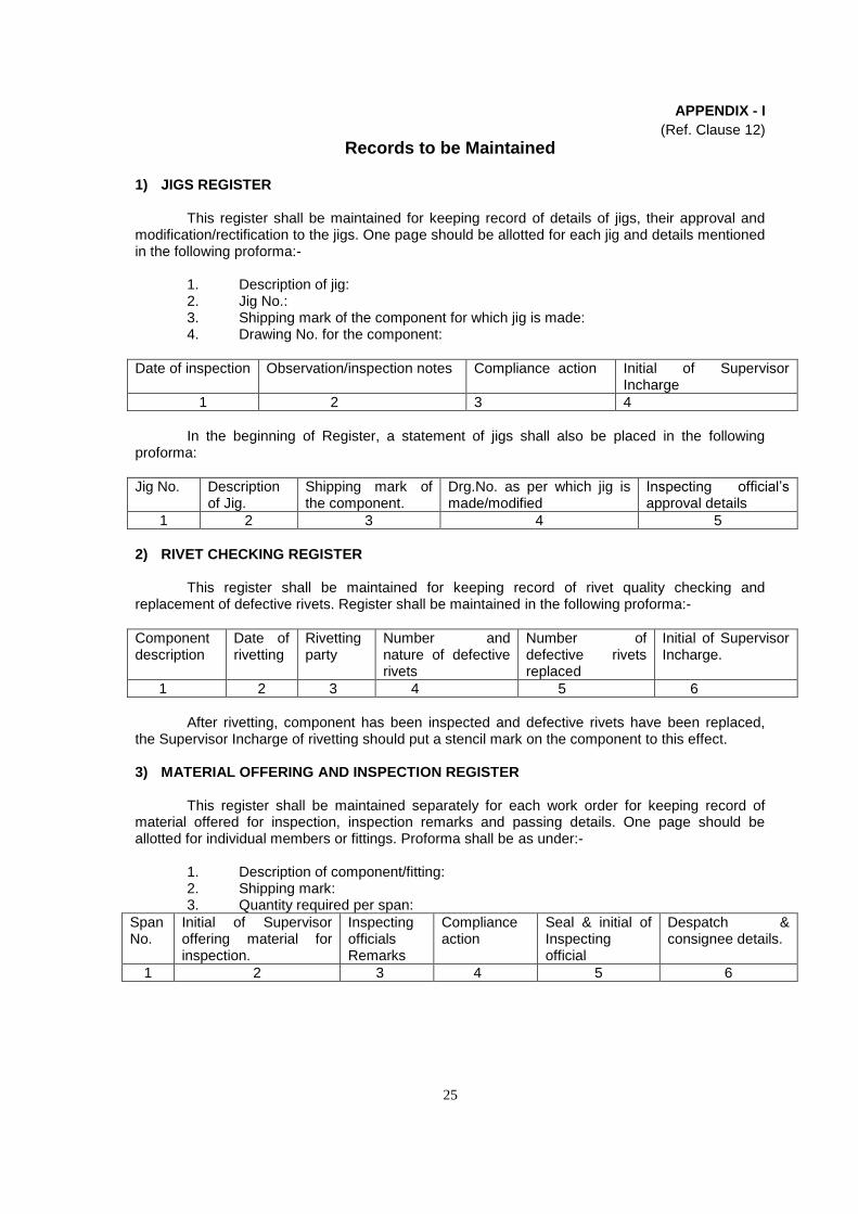
25
APPENDIX - I
(Ref. Clause 12)
Records to be Maintained
1) JIGS REGISTER
This register shall be maintained for keeping record of details of jigs, their approval and modification/rectification to the jigs. One page should be allotted for each jig and details mentioned in the following proforma:-
1. Description of jig:2. Jig No.:3. Shipping mark of the component for which jig is made:4. Drawing No. for the component:
Date of inspection Observation/inspection notes Compliance action Initial of Supervisor Incharge
1 2 3 4
In the beginning of Register, a statement of jigs shall also be placed in the following proforma:
Jig No. Description of Jig.
Shipping mark of the component.
Drg.No. as per which jig is made/modified
Inspecting official’s approval details
1 2 3 4 5
2) RIVET CHECKING REGISTER
This register shall be maintained for keeping record of rivet quality checking and replacement of defective rivets. Register shall be maintained in the following proforma:-
Component description
Date of rivetting
Rivetting party
Number and nature of defective rivets
Number of defective rivets replaced
Initial of Supervisor Incharge.
1 2 3 4 5 6
After rivetting, component has been inspected and defective rivets have been replaced, the Supervisor Incharge of rivetting should put a stencil mark on the component to this effect.
3) MATERIAL OFFERING AND INSPECTION REGISTER
This register shall be maintained separately for each work order for keeping record of material offered for inspection, inspection remarks and passing details. One page should be allotted for individual members or fittings. Proforma shall be as under:-
1. Description of component/fitting:2. Shipping mark:3. Quantity required per span:
Span No.
Initial of Supervisor offering material for inspection.
Inspecting officials Remarks
Compliance action
Seal & initial of Inspecting official
Despatch & consignee details.
1 2 3 4 5 6
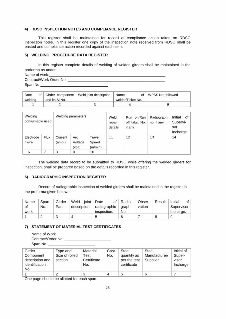
26
4) RDSO INSPECTION NOTES AND COMPLIANCE REGISTER
This register shall be maintained for record of compliance action taken on RDSO Inspection notes. In this register one copy of the inspection note received from RDSO shall be pasted and compliance action recorded against each item.
5) WELDING PROCEDURE DATA REGISTER
In this register complete details of welding of welded girders shall be maintained in the
proforma as under:
Name of work:_______________________________________________________
Contract/Work Order No. ______________________________________________
Span No.________________________________
Date of
welding
Girder component
and its Sl.No.
Weld joint description Name of
welder/Ticket No.
WPSS No. followed
1 2 3 4 5
Welding
consumable used
Welding parameters Weld
repair
details
Run on/Run
off tabs. No.
if any
Radiograph
no. if any
Initial of
Supervi-
sor
Incharge.
Electrode
/ wire
Flux Current
(amp.)
Arc
Voltage
(volt)
Travel
Speed
(m/min)
11 12 13 14
6 7 8 9 10
The welding data record to be submitted to RDSO while offering the welded girders for
inspection, shall be prepared based on the details recorded in this register.
6) RADIOGRAPHIC INSPECTION REGISTER
Record of radiographic inspection of welded girders shall be maintained in the register in
the proforma given below:
Name
of
work
Span
No.
Girder
Part
Weld joint
description
Date of
radiographic
inspection.
Radio-
graph
No.
Obser-
vation
Result Initial of
Supervisor
Incharge.
1 2 3 4 5 6 7 8 9
7) STATEMENT OF MATERIAL TEST CERTIFICATES
Name of Work_____________________________
Contract/Order No..______________________
Span No..______________________
Girder
Component
description and
identification
No.
Type and
Size of rolled
section
Material
Test
Certificate
No.
Cast
No.
Steel
quantity as
per the test
certificate
Steel
Manufacturer/
Supplier
Initial of
Super-
visor
Incharge
.
1 2 3 4 5 6 7
One page should be allotted for each span.
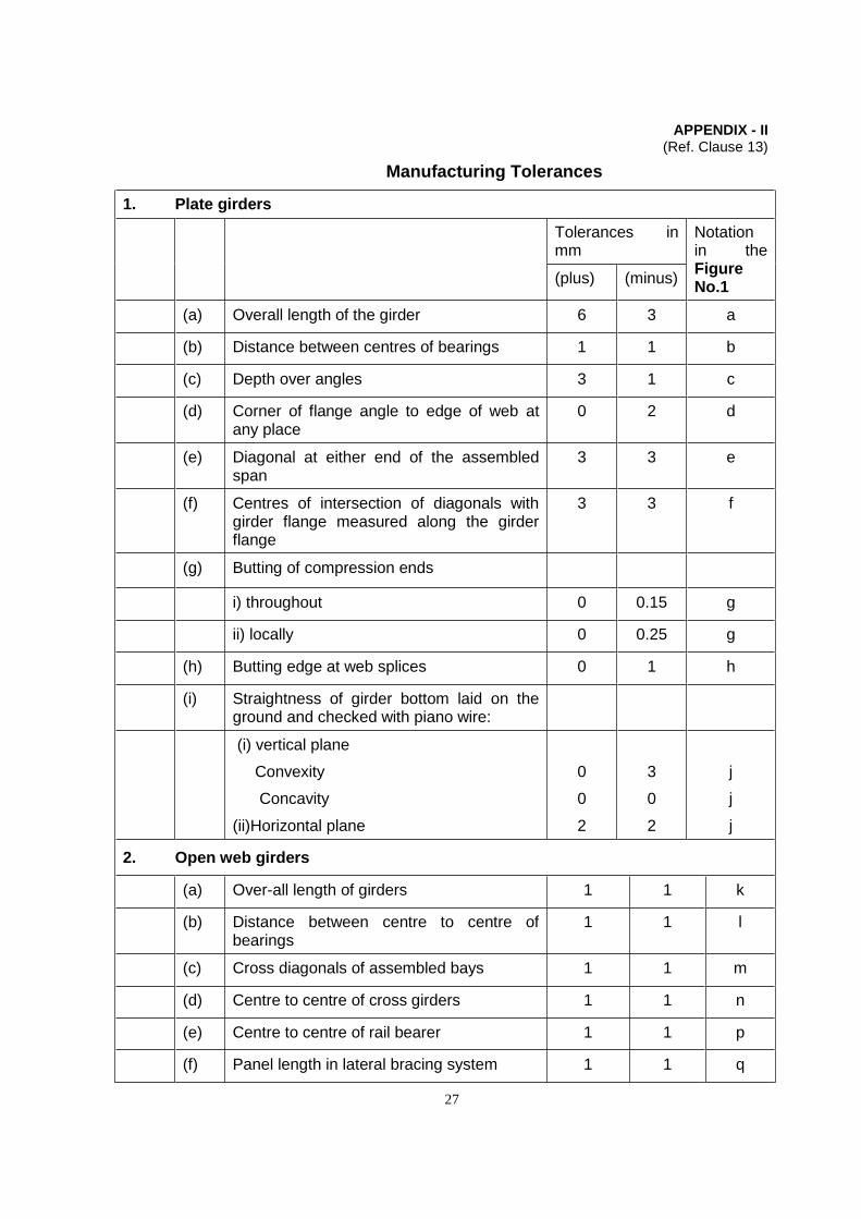
27
APPENDIX - II (Ref. Clause 13)
Manufacturing Tolerances
1. Plate girders
Tolerances in mm
Notation in the Figure No.1
(plus) (minus)
(a) Overall length of the girder 6 3 a
(b) Distance between centres of bearings 1 1 b
(c) Depth over angles 3 1 c
(d) Corner of flange angle to edge of web at any place
0 2 d
(e) Diagonal at either end of the assembled span
3 3 e
(f) Centres of intersection of diagonals with girder flange measured along the girder flange
3 3 f
(g) Butting of compression ends
i) throughout 0 0.15 g
ii) locally 0 0.25 g
(h) Butting edge at web splices 0 1 h
(i) Straightness of girder bottom laid on the ground and checked with piano wire:
(i) vertical plane
Convexity
Concavity
(ii)Horizontal plane
0
0
2
3
0
2
j
j
j
2. Open web girders
(a) Over-all length of girders 1 1 k
(b) Distance between centre to centre of bearings
1 1 l
(c) Cross diagonals of assembled bays 1 1 m
(d) Centre to centre of cross girders 1 1 n
(e) Centre to centre of rail bearer 1 1 p
(f) Panel length in lateral bracing system 1 1 q
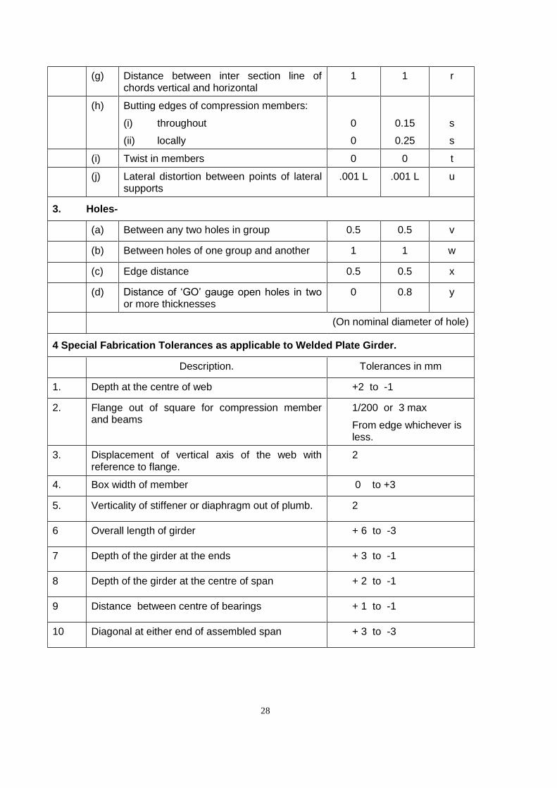
28
(g) Distance between inter section line of chords vertical and horizontal
1 1 r
(h) Butting edges of compression members:
(i) throughout
(ii) locally
0
0
0.15
0.25
s
s
(i) Twist in members 0 0 t
(j) Lateral distortion between points of lateral supports
.001 L .001 L u
3. Holes-
(a) Between any two holes in group 0.5 0.5 v
(b) Between holes of one group and another 1 1 w
(c) Edge distance 0.5 0.5 x
(d) Distance of ‘GO’ gauge open holes in two or more thicknesses
0 0.8 y
(On nominal diameter of hole)
4 Special Fabrication Tolerances as applicable to Welded Plate Girder.
Description. Tolerances in mm
1. Depth at the centre of web +2 to -1
2. Flange out of square for compression member and beams
1/200 or 3 max
From edge whichever is less.
3. Displacement of vertical axis of the web with reference to flange.
2
4. Box width of member 0 to +3
5. Verticality of stiffener or diaphragm out of plumb. 2
6 Overall length of girder + 6 to -3
7 Depth of the girder at the ends + 3 to -1
8 Depth of the girder at the centre of span + 2 to -1
9 Distance between centre of bearings + 1 to -1
10 Diagonal at either end of assembled span + 3 to -3
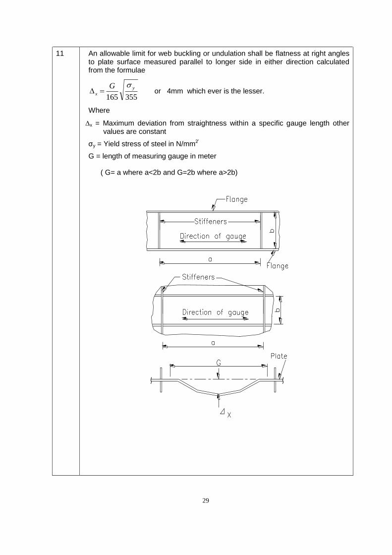
29
11 An allowable limit for web buckling or undulation shall be flatness at right angles to plate surface measured parallel to longer side in either direction calculated from the formulae
355165
y
x
G or 4mm which ever is the lesser.
Where
x = Maximum deviation from straightness within a specific gauge length othervalues are constant
σy = Yield stress of steel in N/mm2’
G = length of measuring gauge in meter
( G= a where a<2b and G=2b where a>2b)

30
APPENDIX - III
(Ref. Clauses 20 & 34)
Erection of Open Web Girder Span
1. The joints of the chords shall be drifted, bolted and preferably rivetted to their geometric outline.
2. All other members are to be elastically strained into position by external forces, so that as many holes as possible are fair when filled with rivets.
3. Drifting of joints shall be avoided as far as possible, and when necessary should be done with greater care and under close expert supervision. Hammers not exceeding 1 kg.(2 lb) in weight should be used with turned barrel drifts and a number of holes drifted simultaneously, the effect of the drifting being checked by observation of adjacent unfilled holes.
4. The first procedure during erection consists of placing camber jacks in position on which to support the structure. The camber jacks should be set with their top level and with sufficient run-out to allow for lowering of panel points except the centre by the necessary amount to produce the required camber in the main girders. It is essential that the camber is accurately maintained throughout the process of erection and it should be constantly checked. The jacks shall be spaced so that they will support the ends of the main girders and the panel points. The bottom chord members shall then be placed on the camber jacks carefully levelled and checked for straightness and the joints made and rivetted up.
5. The vertical and diagonal web members, except the end posts, shall then be erected in their proper position on the bottom chords. Temporary top gussets, the positions of the holes in which they are corrected, for the camber change of length in the members, should be used to connect the top ends of the members. This will ensure that the angles between the members at the bottom joints are as given by the nominal outline of the girders. The verticals and diagonals shall then be rivetted to the lower chords.
6. All panel points, except the centre, shall now be lowered by the amount to produce the correct camber in the main girders as shown on the camber diagram.
7. The top chord shall be erected piece by piece working symmetrically starting from the centre outwards, each piece being cambered in turn
8. The temporary top gussets, if used, shall be replaced by the permanent gussets in the same sequence as the erection of the top boom members.
9. The end posts shall be erected last. The upper end connection should preferably be made first and if there is no splice in the end raker, the final closure made at the bottom end connection. If there is a splice, the final closure should be made at the splice.
10. When cantilever method of erection is used, the above procedure does not apply.
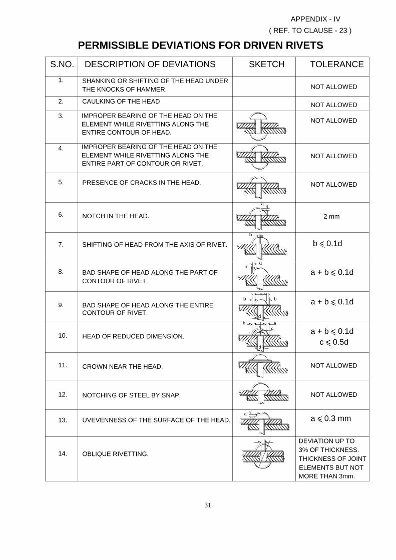
31
SHANKING OR SHIFTING OF THE HEAD UNDER
IMPROPER BEARING OF THE HEAD ON THE
ELEMENT WHILE RIVETTING ALONG THE
SHIFTING OF HEAD FROM THE AXIS OF RIVET.
BAD SHAPE OF HEAD ALONG THE PART OF
BAD SHAPE OF HEAD ALONG THE ENTIRE
UVEVENNESS OF THE SURFACE OF THE HEAD.
IMPROPER BEARING OF THE HEAD ON THE
ELEMENT WHILE RIVETTING ALONG THE
DESCRIPTION OF DEVIATIONS
PERMISSIBLE DEVIATIONS FOR DRIVEN RIVETS
7.
CONTOUR OF RIVET.
HEAD OF REDUCED DIMENSION.
CROWN NEAR THE HEAD.
NOTCHING OF STEEL BY SNAP.
OBLIQUE RIVETTING.
CONTOUR OF RIVET.
12.
14.
13.
11.
10.
9.
8.
THE KNOCKS OF HAMMER.
PRESENCE OF CRACKS IN THE HEAD.
CAULKING OF THE HEAD
ENTIRE CONTOUR OF HEAD.
NOTCH IN THE HEAD.
ENTIRE PART OF CONTOUR OR RIVET.
2.
6.
5.
4.
3.
S.NO.
1.
b < 0.1d
DEVIATION UP TO
3% OF THICKNESS.
THICKNESS OF JOINT
ELEMENTS BUT NOT
MORE THAN 3mm.
a
b
b
b
d
c
a
d
ab
a
NOT ALLOWED
a < 0.3 mm
NOT ALLOWED
c < 0.5d
a + b < 0.1d
a + b < 0.1d
a + b < 0.1d
( REF. TO CLAUSE - 23 )
APPENDIX - IV
b
a
SKETCH
NOT ALLOWED
2 mm
NOT ALLOWED
NOT ALLOWED
NOT ALLOWED
TOLERANCE
NOT ALLOWED
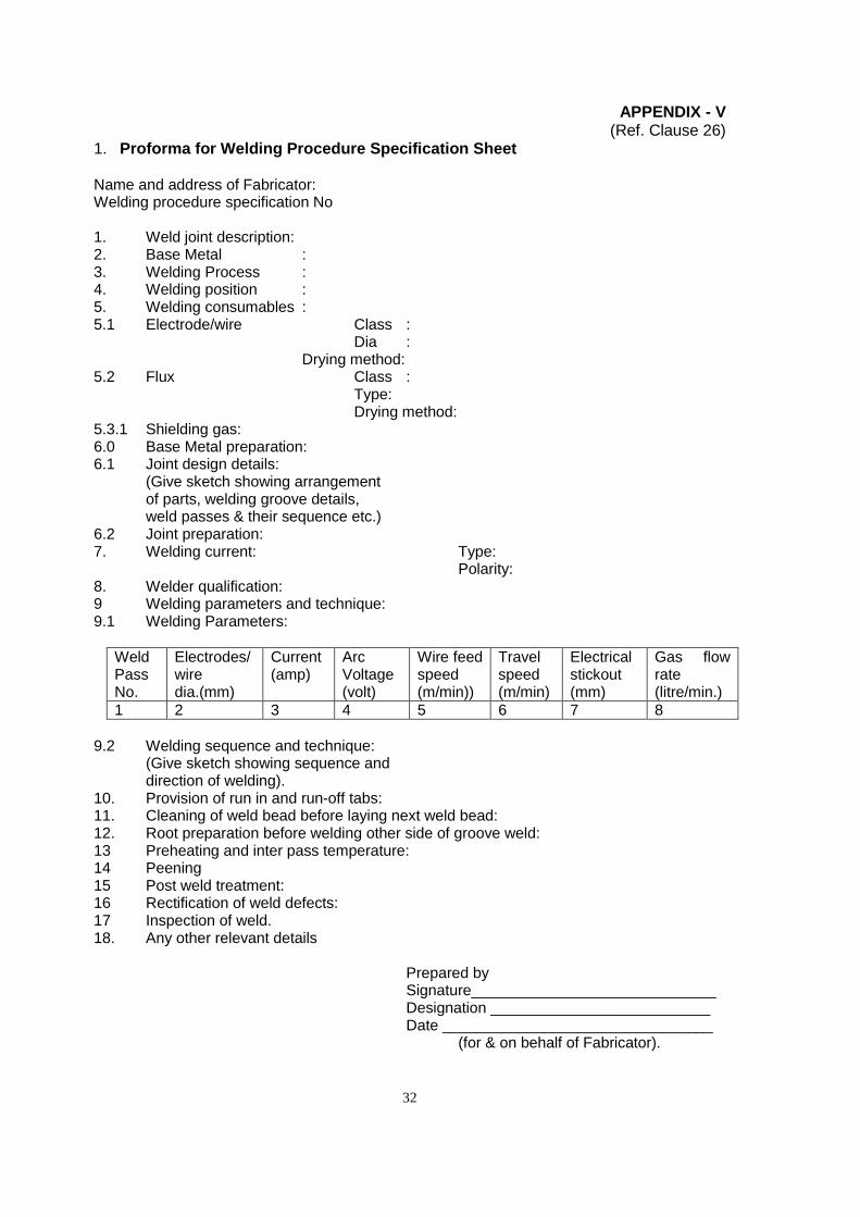
32
APPENDIX - V (Ref. Clause 26)
1. Proforma for Welding Procedure Specification Sheet Name and address of Fabricator: Welding procedure specification No 1. Weld joint description: 2. Base Metal : 3. Welding Process : 4. Welding position : 5. Welding consumables : 5.1 Electrode/wire Class : Dia : Drying method: 5.2 Flux Class : Type: Drying method: 5.3.1 Shielding gas: 6.0 Base Metal preparation: 6.1 Joint design details:
(Give sketch showing arrangement of parts, welding groove details, weld passes & their sequence etc.)
6.2 Joint preparation: 7. Welding current: Type:
Polarity: 8. Welder qualification: 9 Welding parameters and technique: 9.1 Welding Parameters:
Weld Pass No.
Electrodes/ wire dia.(mm)
Current (amp)
Arc Voltage (volt)
Wire feed speed (m/min))
Travel speed (m/min)
Electrical stickout (mm)
Gas flow rate (litre/min.)
1 2 3 4 5 6 7 8
9.2 Welding sequence and technique:
(Give sketch showing sequence and direction of welding).
10. Provision of run in and run-off tabs: 11. Cleaning of weld bead before laying next weld bead: 12. Root preparation before welding other side of groove weld: 13 Preheating and inter pass temperature: 14 Peening 15 Post weld treatment: 16 Rectification of weld defects: 17 Inspection of weld. 18. Any other relevant details
Prepared by Signature_____________________________ Designation __________________________ Date ________________________________
(for & on behalf of Fabricator).
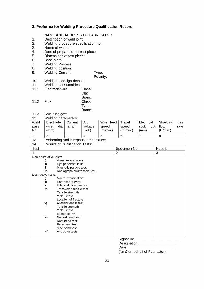
33
2. Proforma for Welding Procedure Qualification Record NAME AND ADDRESS OF FABRICATOR 1. Description of weld joint: 2. Welding procedure specification no.: 3. Name of welder: 4. Date of preparation of test piece: 5. Dimensions of test piece: 6. Base Metal: 7. Welding Process: 8. Welding position: 9. Welding Current: Type:
Polarity: 10 Weld joint design details: 11 Welding consumables: 11.1 Electrode/wire Class:
Dia: Brand:
11.2 Flux Class: Type: Brand:
11.3 Shielding gas: 12. Welding parameters: Weld pass No.
Electrode wire dia (mm)
Current (amp)
Arc voltage (volt)
Wire feed speed (m/min.)
Travel speed (m/min.)
Electrical stick out (mm)
Shielding gas flow rate (lit/min.)
1 2 3 4 5 6 7 8
13. Preheating and interpass temperature: 14. Results of Qualification Tests:
Test Specimen No. Result.
1 2 3 Non-destructive tests:
i) Visual examination: ii) Dye penetrant test: iii) Magnetic particle test: iv) Radiographic/Ultrasonic test:
Destructive tests: i) Macro-examination: ii) Hardness survey: iii) Fillet weld fracture test: iv) Transverse tensile test:
Tensile strength Yield Stress Location of fracture
v) All-weld tensile test: Tensile strength Yield Stress Elongation %
vi) Guided bend test: Root bend test Face bend test Side bend test
vii) Any other tests:
Signature _______________________ Designation ___________________ Date _________________________ (for & on behalf of Fabricator).
34
APPENDIX - VI (Ref. Clause 31)
Tolerances & Specification for Knuckle and Roller Bearings
1. Rollers
No roller shall vary in diameter, from that shown on the contract drawings, by more than ±0.04mm.
2. Knuckle castings and pins (Interchangeable work)
a) Knuckle Pin
The diameter shall not be greater than D, nor less than D-0.2 mm.
b) Knuckle Castings
The knuckle castings must be bored greater than D, but not greater than D+0.3 mm.
Where D, in all cases is the diameter given on the contract drawings.
3. Knuckle castings and pins(non-interchangeable work)
If sets of bearings are not made interchangeable but are made separately and the pins and knuckles all fitted together than the minus tolerance on the pin, and the plus tolerance on the bore of the knuckles may be varied provided that the difference between the diameter of the pin and the diameter of the knuckle does not exceed 0.5mm. also in this case all sets of bearing are to be given a consecutive number and each component part shall have this allotted number stamped upon it and encircled in white paint in the manner shown on the sketch.
4. Marking
Accurate centre marks should be made on the four sides of the bottom slab of the bearing to facilitate positioning during erection.
5. Thickness of castings (Interchangeable and non inter-changeable work )
No minus tolerance will be allowed in the thickness of any part of any of the castings. The edges of all ribs shall be of the thickness shown on the contract drawings and shall be parallel throughout their length.
35
APPENDIX - VII (Ref.Clause 39)
Specification for Metallising with Sprayed Aluminium for Bridge Girders
1. Surface Preparation
The surface shall be thoroughly cleaned and roughened by compressed air blasting orcentrifugal blasting with a suitable abrasive material in accordance with Clause 3 ofIS:6586. Immediately, before spraying it shall be free from grease, scale, rust,moisture or other foreign matter. It shall be comparable in roughness with a referencesurface produced in accordance with appendix A of IS:5905 and shall provide anadequate key for the subsequently sprayed metal coating
2. Metal Spraying
The metal spraying shall be carried out as soon as possible after surface preparationbut in any case within such period that the surface is still completely clean, dry andwithout visible oxidation. If deterioration in the surface to be coated is observed bycomparison with a freshly prepared metal surface of similar quality which hasundergone the same preparation, the preparation treatment should be repeated onthe surface to be coated.
The wire method shall be used for the purpose of metallising the diameter of the wirebeing 3mm or 5mm. Specified thickness of coating shall be applied in multiple layersand in no case less than 2 passes of the metal spraying unit shall be made over everypart of the surface. At least one layer of the coating must be applied within 4 hours ofblasting and the surface must be completely coated to the specified thickness within 8hours of blasting.
2.1 Purity of Aluminium
The chemical composition of aluminium to be sprayed shall be 99.5% aluminium conforming to IS:2590.
2.2 Appearance Of The Coating
The surface of the sprayed coating shall be of uniform texture and free from lumps, coarse areas and loosely adherent particles.
2.3 Thickness Of The Coating
The nominal thickness of the coating shall be 150 µ(microns).The minimum local thickness, determined in accordance with procedure given in clause 3.1 below, shall be not less than 110 µ(microns).
3. Shop Painting
Any oil, grease or other contamination should be removed by thorough washing with asuitable thinner until no visible traces exist and the surfaces should be allowed to drythoroughly before application of paint. The coatings may be applied by brush or spray.If sprayed, pressure type spray guns must be used. One coat of wash primer toIS:5666 shall be applied first. After 4 to 6 hours of the application of the wash primer,one coat of Zinc chrome primer to IS:104 with the additional proviso that zinc chrometo be used in the manufacture of primer shall conform to type 2 of IS:51 shall beapplied. After hard drying of zinc chrome primer, one coat of Aluminium paint toIS:2339 (brushing or spraying as required) shall be applied.
36
4. Site Painting
After the steel work is erected at site a second cover coat of Aluminium paint toIS:2339 (brushing or spraying as required) shall be applied after touching up theprimer and the cover coat given in the shop if damaged in transit
5. Method for the Determination of Local Thickness
5.1 Equipment
Any magnetic or electro-magnetic thickness meter that will measure local thickness of a known standard with an accuracy of ± 10 percent.
5.2 Calibration of Instrument
Calibrate and check the meter on one of the following standards(as appropriate):
(I) (Applicable to magnetic and elecro-maganetic meters other than the pull-off type)A soft brass shim ,free from burrs, in contact with the grit-blasted surface of the basemetal prior to its being sprayed. The thickness of the shim shall be measured by micrometer and shall be approximately the same as the thickness of the coating.
(ii) A sprayed metal coating of uniform known thickness approximately the same asthe thickness of the sprayed coating to be tested, applied to a base of similarcomposition and thickness to the article being sprayed, grit-blasted in accordance withClause 1.
5.3 Procedure
For each measurement of local thickness, make an appropriate number of determinations, according to the type of instrument used.
With instrument measuring the average thickness over an area of not less than 0.645 cm2, the local thickness shall be the result of the one reading.
With instruments having one or more pointed or rounded probes, the local thickness shall be the mean of three readings within a circle of 0.645 cm2 area.
With meters having two such probes, each reading shall be the average of two determinations with the probes reversed position.
6. Method Of Test For Adhesion
Using a straight edge and hardened steel scriber which has been ground to a sharp30 degree point, scribe two parallel lines at a distance apart equal to approximately 10times the average coating thickness. In scribing the two lines, apply enough pressureon each occasion to cut through the coating to the base metal in a single stroke.
7. Inspection
7.1 Determination of Local Thickness
The minimum local thickness shall be determined by the method described above.
7.2 Adhesion
The sprayed metal coating shall be subjected to an adhesion test using the method described above. If any part of the coating between the lines breaks away from the base metal, it shall be deemed to have failed the test
Articles, which have been rejected shall have the defective sections blasted clean of all sprayed metal prior to respraying. Where the rejection has been solely due to too thin a coating, sprayed metal of the same quality may be added provided that the surface has been kept dry and is free from visible contamination.
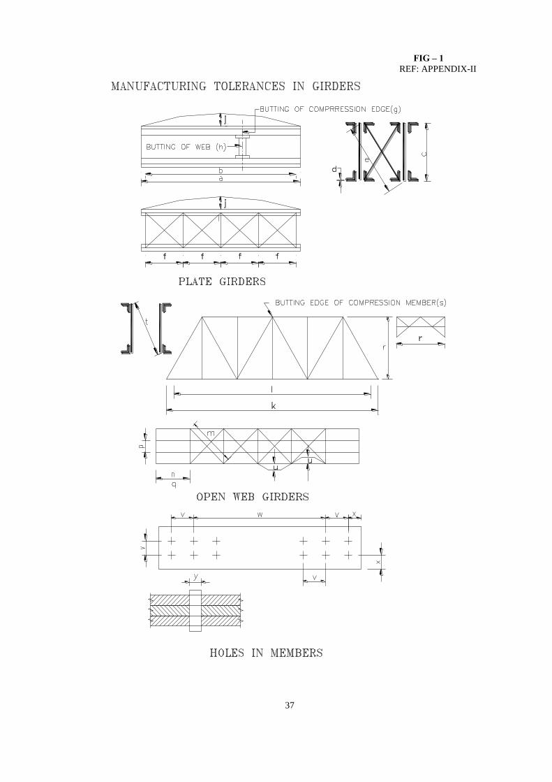
37
FIG – 1 REF: APPENDIX-II
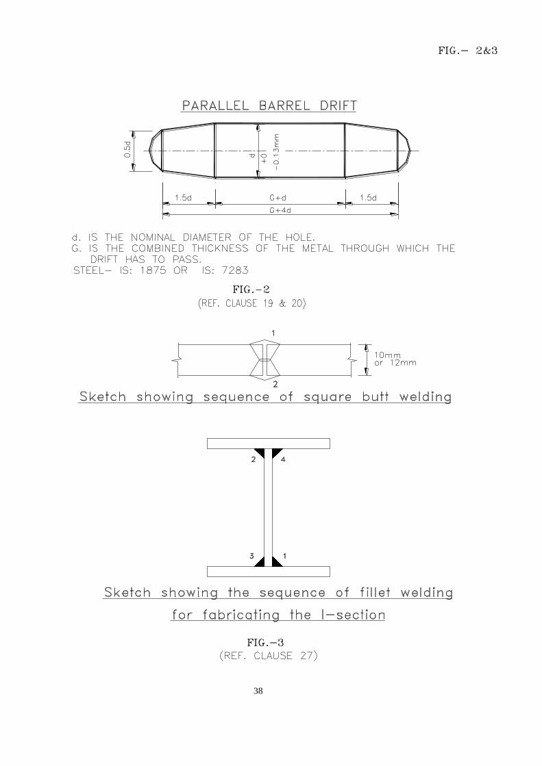
38
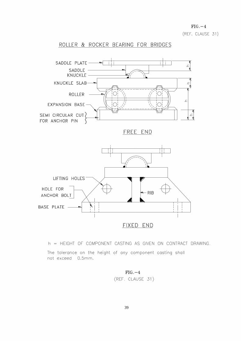
39