Embed Size (px)
Citation preview
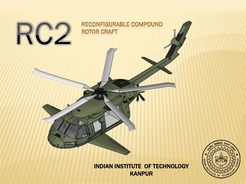
INDIAN INSTITUTE OF TECHNOLOGY
KANPUR

Composite Hub
Advanced Airfoils
Tip Shape
Vibration Isolation System
Self Sealing Fuel Tanks
Extensive use of
CompositesCabin Door
Hingelesss, Good Manoeuverability, Maintainence Free, Foldable
Efficient Lift
Removable, Low Noise, High Speed
Low Vibratoin, Smooth Ride
Multifunction Displays, AFCS, Less pilot work load
Long Life, Corrosion Resistance
Twin Engines with Full Authority Digital Electronic Control
Easy Access, Sliding Cargo Tracks
Tapered, Swept Back, 25% chord Flaps, Reduced Hover Download Optimised Lift in Forward Flight, Removable
Efficient at forward speeds, Reduced Rotor Wake Interaction, Removable
Tractor Configuration, Cant angle, Low Maintainence
Easily configurable interiors
Variable Incidence Stabilator, Improved longitudanal stability, Easy to trim
Safety, Modular
INDIAN INSTITUTE OF TECHNOLOGY KANPUR

BASELINE HELICOPTERS
Kaman UH-2A
•Turbojet-single 2,500 lb static thrust General Electric YJ85
•Trials carried out using a modified UH-2A Seasprite.
•Modifications were made to graft a pair of wings from a Beech Queen Air light executive transport aircraft onto the sides of the lower fuselage, giving the aircraft a wingspan of 35.25 ft
•Reached speeds up to 225 mph.
•Pilots reported that the wings did not hinder autorotation
Lockheed XH-51 A
•Turbojet-2,500 lb static thrust Pratt & Whitney J60-P-2
•A set of wings spanning 16.9 ft in was fitted to the aircraft
•The auxiliary turbojet and stub wings partially unloaded the main rotor in forward flight, reducing the critical blade tip speedand blade angle
•The wings were each equipped with spoilers to assist entry into autorotation at high speed in an emergency. In addition, the horizontal and vertical tail surfaces were enlarged
•On June,1967, the XH-51A Compound set an record for rotorcraft by attaining a speed of 302.6 mph.
Sikorsky X-2
•Propeller-LHTEC T800 Turbo shaft Engine.
•Incorporated the research findings from Sikorsky S-69 coaxial helicopter developed as a part of the Advancing Blade Concept (ABC) program.
•Maximum Speed 250knots.
•The demonstrator also reached a speed of 260 knots in a shallow 2’’ to 3’’ dive.
•Poor Payload / Gross Weight ratio

MISSIONS
Main Rotor
Auxiliary Thrust
Wing
Main Rotor
Main Rotor
Rescue Mission :i) Speed of 192 knots achievable
ii) Reaches destination within the
golden hour.
iii) Both thrust and lift compounded.
iv) TOGW: 12484 lbs
Return Flight : 11284 lbs
Insertion :i) Best range speed of 120 knots.
ii) Carries a heavy payload of 4000 lbs.
iii) Does not require thrust and lift
compounding and hence wings and
propeller are removed.
iv) TOGW: 13600 lbs
Return Flight : 12267 lbs
Resupply :i) Best Range speed of 120 knots.
ii) Lower payload and hence has
lowest gross weight among the
three missions.
iii) This mission also doesn’t require
thrust and lift compounding.
iv) TOGW :12900 lbs
Return Flight : 11750 lbs

MAIN ROTORITEM DETAIL
Radius 21.325 ft
Chord 1.97 ft
Tip Speed 644 ft/s
Solidity 0.147
Twist -2o
Lock Number 12
Mass 920lbs
Hinge Offset 15%R
BERP Tip
This blade tip
shape
reduces
compressibility
and has high
stall angle.
Tip Speed
•The tip speed is limited to 644 ft/s because of compressibility, noise and retreating blade stall effects
Solidity
•The solidity is high because it has lower vibration, noise, and delayed retreating blade stall
Twist
•It has low twist to prevent blade stress during fast forward flight
Aspect Ratio
•Small aspect ratio to ensure natural frequency of 2nd flapping mode is below 3/rev

WING DESIGN
Variable incidence wing
Flaps
Spoilers and
Brakes
Wing Plan form
and Geometry
Aerofoil
•A majority of past compound helicopter
designs have utilized a compromise wing
aspect ratio of around 6 to create a balance
between low induced drag in cruising flight
and hover download minimization.
•Sweep has been used to a moderate degree
on a majority of the past compound aircraft,
mainly as a means of correctly positioning
the wing aerodynamic centre.
•The general thought on the choice of aerofoil section for
compound helicopters has been to use a section of fairly large
thickness, with low drag in cruising flight, a high maximum
lift coefficient and gentle stall.
•It provides the ability to optimize the wing lift ratio.
•It adds to structural complexity of the design, adding to the weight
of the aircraft and the inability to build in components such as
undercarriage and fuel storage into the wing.
•Since wings are used only in search and rescue mission requiring a
large volume of fuel, this concept was not incorporated.
•A trade off which allows the wing lift to be
controlled to a greater degree is the use of
flaps which allows controlled the wing lift
to a greater degree while not impairing the
structural simplicity.
•A plain flap of 25 per cent of the wing
chord length and with a deflection less than
90o, to a void flow separation, could reduce
the download of a wing by the order of 30
per cent.
•Previous experiences with compound
helicopters have indicated that the auto
rotative capabilities are not enhanced
substantially with spoilers hence they
have not been incorporated into our
design.
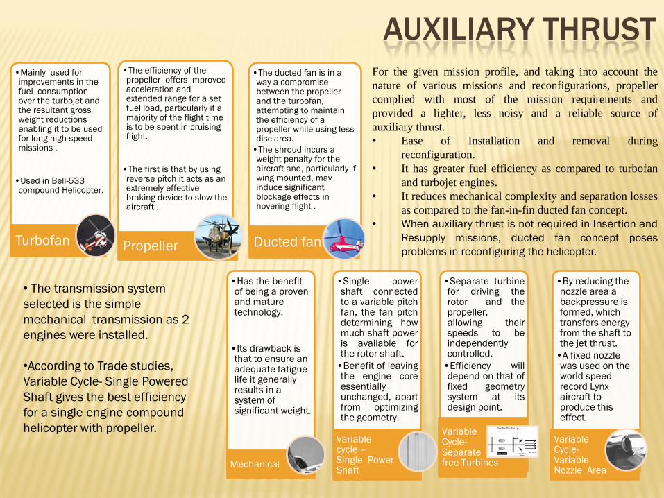
AUXILIARY THRUST•Mainly used for improvements in the fuel consumption over the turbojet and the resultant gross weight reductions enabling it to be used for long high-speed missions .
•Used in Bell-533 compound Helicopter.
Turbofan
•The efficiency of the propeller offers improved acceleration and extended range for a set fuel load, particularly if a majority of the flight time is to be spent in cruising flight.
•The first is that by using reverse pitch it acts as an extremely effective braking device to slow the aircraft .
Propeller
•The ducted fan is in a way a compromise between the propeller and the turbofan, attempting to maintain the efficiency of a propeller while using less disc area.
•The shroud incurs a weight penalty for the aircraft and, particularly if wing mounted, may induce significant blockage effects in hovering flight .
Ducted fan
•Has the benefit of being a proven and mature technology.
•Its drawback is that to ensure an adequate fatigue life it generally results in a system of significant weight.
Mechanical
•Single powershaft connectedto a variable pitchfan, the fan pitchdetermining howmuch shaft poweris available forthe rotor shaft.
•Benefit of leavingthe engine coreessentiallyunchanged, apartfrom optimizingthe geometry.
Variable cycle –Single Power Shaft
•Separate turbinefor driving therotor and thepropeller,allowing theirspeeds to beindependentlycontrolled.
•Efficiency willdepend on that offixed geometrysystem at itsdesign point.
Variable Cycle-Separate free Turbines
•By reducing the nozzle area a backpressure is formed, which transfers energy from the shaft to the jet thrust.
•A fixed nozzle was used on the world speed record Lynx aircraft to produce this effect.
Variable Cycle-Variable Nozzle Area
For the given mission profile, and taking into account the
nature of various missions and reconfigurations, propeller
complied with most of the mission requirements and
provided a lighter, less noisy and a reliable source of
auxiliary thrust.
• Ease of Installation and removal during
reconfiguration.
• It has greater fuel efficiency as compared to turbofan
and turbojet engines.
• It reduces mechanical complexity and separation losses
as compared to the fan-in-fin ducted fan concept.
• When auxiliary thrust is not required in Insertion and
Resupply missions, ducted fan concept poses
problems in reconfiguring the helicopter.
• The transmission system
selected is the simple
mechanical transmission as 2
engines were installed.
•According to Trade studies,
Variable Cycle- Single Powered
Shaft gives the best efficiency
for a single engine compound
helicopter with propeller.
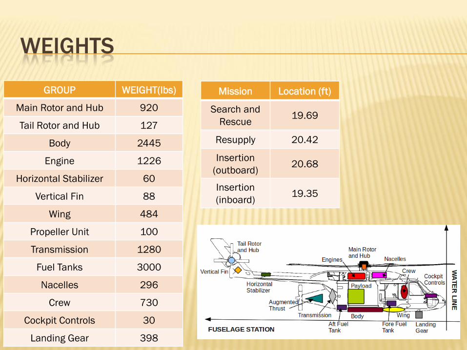
WEIGHTS
Mission Location (ft)
Search and
Rescue19.69
Resupply 20.42
Insertion
(outboard)20.68
Insertion
(inboard)19.35
GROUP WEIGHT(lbs)
Main Rotor and Hub 920
Tail Rotor and Hub 127
Body 2445
Engine 1226
Horizontal Stabilizer 60
Vertical Fin 88
Wing 484
Propeller Unit 100
Transmission 1280
Fuel Tanks 3000
Nacelles 296
Crew 730
Cockpit Controls 30
Landing Gear 398

TRIM
Pitch Moment Equation (gives an estimate of Β1c )
Roll Moment Equation (gives
Β1s )
Calculation of Tail Rotor Thrust
coefficient Cat
Calculation of Roll Angle φ
Horizontal Force Equation
(calculation of α,Cat)
Vertical Force Equation (calculation
of Ct)
Calculation of inflow ratio λ
Estimation of θ0,θ1c,θ1s
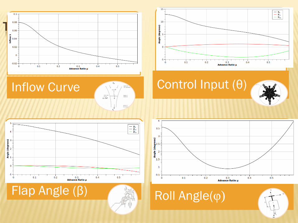
TRIM CURVES
Inflow Curve Control Input (θ)
Flap Angle (β) Roll Angle(φ)

Search &
Rescue
Insertion
Resupply
PERFORMANCE

REVERSE FLOW AND RETREATING STALL
Reverse Flow
Region
Advancing
Side
Advancing
Side
Retreating
SideRetreating
Side
Stalled Region
Stalled Region
To prevent retreating blade
stall, the airfoil is designed in
such a way that it has a high
stall angle limit. The airfoil als
has a high Mach drag
divergence number.
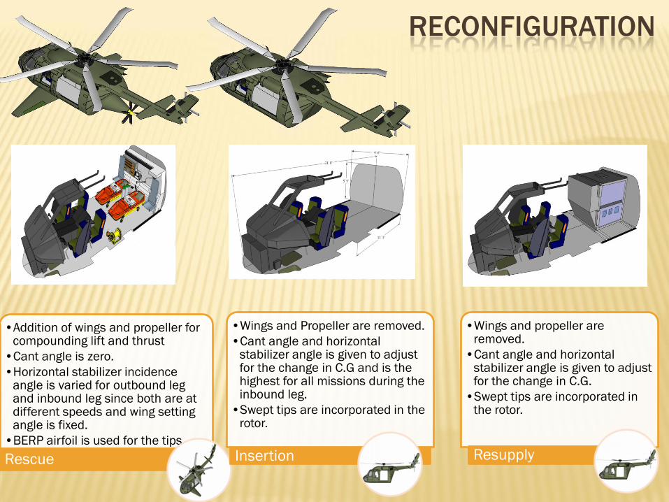
RECONFIGURATION
•Addition of wings and propeller for compounding lift and thrust
•Cant angle is zero.
•Horizontal stabilizer incidence angle is varied for outbound leg and inbound leg since both are at different speeds and wing setting angle is fixed.
•BERP airfoil is used for the tips.
Rescue
•Wings and Propeller are removed.
•Cant angle and horizontal stabilizer angle is given to adjust for the change in C.G and is the highest for all missions during the inbound leg.
•Swept tips are incorporated in the rotor.
Insertion
•Wings and propeller are removed.
•Cant angle and horizontal stabilizer angle is given to adjust for the change in C.G.
•Swept tips are incorporated in the rotor.
Resupply

SEARCH AND RESCUE CONFIGURATION

POSSIBLE INTERIOR ARRANGEMENTS
IATA
Container
Type 8
IATA
Container
Type 8D
6
Passengers
Cargo
Container
Transport

IMPORTANT COMPONENTS
Wing Flaps
EngineAuxiliary
Propulsion
Tail
Hub

COST
ANALYSIS
•Depreciation Charges
•Dpr= Pr/10000
•Direct Operating Cost
•DOCh=2.25*Dpr/10000 +0.7*Q
where Q is the fuel consumption
in kg/hr.
Direct Operating Cost
•Time of Mission ~ 3 hrs
•Fuel Consumed ~ 1360 kg
•Q=453.33 kg/hr
•Dpr=600
•DOCh=$317.468 /hr
Search & Rescue
•Time of Mission ~4 hrs
•Fuel Consumed~1040 kg
•Q=260 kg/hr
•Dpr=600
•DOCh=$182.135 /hr
Insertion
•Time of Mission ~4 hrs
•Fuel consumed ~900 kg
•Q=225 kg/hr
•Dpr=600
•DOCh=$157.635 /hr
Resupply
•Calculated using Harris and Scully relation.
•It is found that price increases with disk loading.
•Engine power is also a key factor influencing the price
•Pr=$5.1 million
•By factoring in advanced research and development technologies Pr=$ 6 million.
Relative Price of Unit