Embed Size (px)
Citation preview
Index of /ds/BC/
Name Last modified Size Description
Parent Directory
BC237.pdf 22-Dec-99 00:02 70K
BC237_238_239.pdf 17-Apr-99 00:00 70K
BC238.pdf 22-Dec-99 00:02 70K
BC239.pdf 22-Dec-99 00:02 70K
BC307.pdf 22-Dec-99 00:02 69K
BC307_308_309.pdf 17-Apr-99 00:00 69K
BC308.pdf 22-Dec-99 00:02 69K
BC309.pdf 22-Dec-99 00:02 69K
BC327.pdf 22-Dec-99 00:02 92K
BC327_BC328.pdf 17-Apr-99 00:00 92K
BC328.pdf 22-Dec-99 00:02 92K
BC337-16.pdf 22-Dec-99 00:02 25K
BC337-25.pdf 22-Dec-99 00:02 25K
BC337.pdf 22-Dec-99 00:02 31K
BC337_338.pdf 17-Apr-99 00:00 31K
BC338.pdf 22-Dec-99 00:02 31K
BC368.pdf 22-Dec-99 00:02 35K
BC546.pdf 22-Dec-99 00:02 70K
BC546_547_548_549_550+ 20-Apr-99 00:00 70K
BC547.pdf 11-Feb-00 00:00 70K
BC547A.pdf 11-Feb-00 00:00 70K
BC547B.pdf 11-Feb-00 00:00 70K
BC547C.pdf 11-Feb-00 00:00 70K
BC548.pdf 11-Feb-00 00:00 70K
BC548A.pdf 22-Dec-99 00:02 21K
BC548B.pdf 22-Dec-99 00:02 21K
BC548C.pdf 22-Dec-99 00:02 21K
BC549.pdf 22-Dec-99 00:02 70K
BC550.pdf 22-Dec-99 00:02 70K
BC556.pdf 22-Dec-99 00:02 69K
BC556_557_558_559_560+ 20-Apr-99 00:00 69K
BC557.pdf 22-Dec-99 00:02 69K
BC558.pdf 22-Dec-99 00:02 69K
BC559.pdf 22-Dec-99 00:02 69K
BC560.pdf 22-Dec-99 00:02 69K
BC635.pdf 22-Dec-99 00:02 62K
BC635_637_639.pdf 20-Apr-99 00:00 62K
BC636.pdf 22-Dec-99 00:02 62K
BC636_638_640.pdf 20-Apr-99 00:00 62K
BC637.pdf 22-Dec-99 00:02 62K
BC638.pdf 22-Dec-99 00:02 62K
BC639.pdf 22-Dec-99 00:02 62K
BC640.pdf 22-Dec-99 00:02 62K
BC807-16.pdf 22-Dec-99 00:02 35K
BC807-25.pdf 22-Dec-99 00:02 35K
BC807-40.pdf 22-Dec-99 00:02 35K
BC807.pdf 22-Dec-99 00:02 84K
BC807_BC808.pdf 20-Apr-99 00:00 84K
BC808.pdf 22-Dec-99 00:02 84K
BC817-25.pdf 22-Dec-99 00:02 38K
BC817-40.pdf 22-Dec-99 00:02 38K
BC817.pdf 22-Dec-99 00:02 31K
BC817_BC818.pdf 20-Apr-99 00:00 31K
BC818.pdf 22-Dec-99 00:02 31K
BC846.pdf 22-Dec-99 00:02 68K
BC846_847_848_849_850+ 20-Apr-99 00:00 68K
BC847.pdf 22-Dec-99 00:02 68K
BC848.pdf 22-Dec-99 00:02 68K
BC849.pdf 22-Dec-99 00:02 68K
BC850.pdf 22-Dec-99 00:02 68K
BC856.pdf 22-Dec-99 00:02 67K
BC856_857_858_859_860+ 20-Apr-99 00:00 67K
BC857.pdf 22-Dec-99 00:02 67K
BC857A.pdf 22-Dec-99 00:02 40K
BC857B.pdf 22-Dec-99 00:02 40K
BC857C.pdf 22-Dec-99 00:02 40K
BC858.pdf 22-Dec-99 00:02 67K
BC859.pdf 22-Dec-99 00:02 67K
BC860.pdf 22-Dec-99 00:02 67K
BCP52.pdf 22-Dec-99 00:02 46K
BCP54.pdf 22-Dec-99 00:02 39K
BCV26.pdf 22-Dec-99 00:02 36K
BCV27.pdf 22-Dec-99 00:02 52K
BCW29.pdf 22-Dec-99 00:02 31K
BCW30.pdf 22-Dec-99 00:02 24K
BCW31.pdf 22-Dec-99 00:02 27K
BCW60A.pdf 22-Dec-99 00:02 31K
BCW60A_B_C_D.pdf 20-Apr-99 00:00 31K
BCW60B.pdf 22-Dec-99 00:02 31K
BCW60C.pdf 22-Dec-99 00:02 31K
BCW60D.pdf 22-Dec-99 00:02 31K
BCW61A.pdf 22-Dec-99 00:02 32K
BCW61A_B_C_D.pdf 20-Apr-99 00:00 32K
BCW61B.pdf 22-Dec-99 00:02 32K
BCW61C.pdf 22-Dec-99 00:02 32K
BCW61D.pdf 22-Dec-99 00:02 32K
BCW65C.pdf 22-Dec-99 00:02 37K
BCW68G.pdf 22-Dec-99 00:02 37K
BCW71.pdf 22-Dec-99 00:02 31K
BCX70G.pdf 22-Dec-99 00:02 31K
BCX70H.pdf 22-Dec-99 00:02 31K
BCX70J.pdf 22-Dec-99 00:02 31K
BCX70K.pdf 22-Dec-99 00:02 31K
BCX71G.pdf 22-Dec-99 00:02 31K
BCX71H.pdf 22-Dec-99 00:02 31K
BCX71J.pdf 22-Dec-99 00:02 31K
BCX71K.pdf 22-Dec-99 00:02 31K
BCX79.pdf 22-Dec-99 00:02 23K
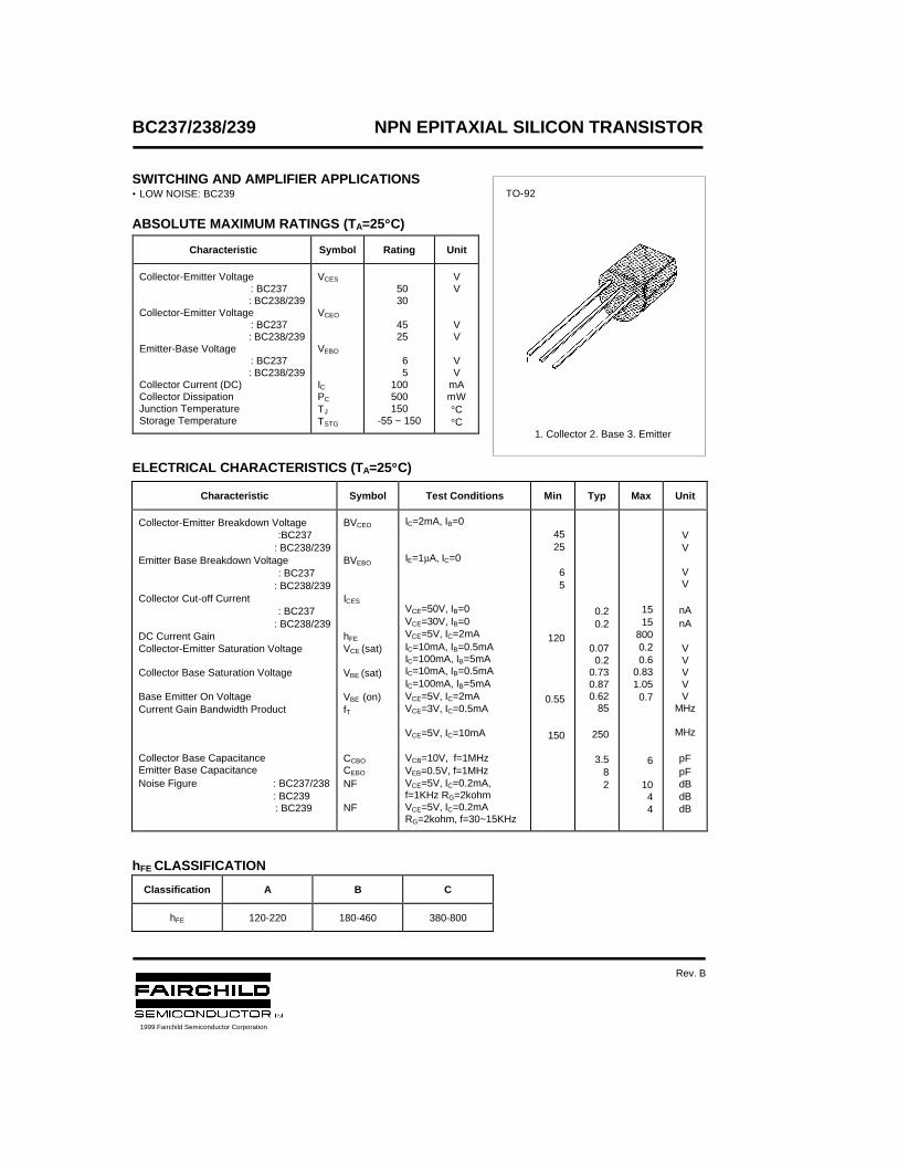
BC237/238/239 NPN EPITAXIAL SILICON TRANSISTOR
SWITCHING AND AMPLIFIER APPLICATIONS• LOW NOISE: BC239
ABSOLUTE MAXIMUM RATINGS (TA=25°°C)
ELECTRICAL CHARACTERISTICS (TA=25°°C)
hFE CLASSIFICATION
Characteristic Symbol Rating Unit
Collector-Emitter Voltage : BC237
: BC238/239Collector-Emitter Voltage
: BC237: BC238/239
Emitter-Base Voltage : BC237
: BC238/239Collector Current (DC)Collector DissipationJunction TemperatureStorage Temperature
VCES
VCEO
VEBO
ICPC
TJ
TSTG
50 30
45 25
6 5100500150
-55 ~ 150
VV
VV
VV
mAmW°C°C
Characteristic Symbol Test Conditions Min Typ Max Unit
Collector-Emitter Breakdown Voltage :BC237
: BC238/239Emitter Base Breakdown Voltage
: BC237: BC238/239
Collector Cut-off Current : BC237
: BC238/239DC Current GainCollector-Emitter Saturation Voltage
Collector Base Saturation Voltage
Base Emitter On VoltageCurrent Gain Bandwidth Product
Collector Base CapacitanceEmitter Base CapacitanceNoise Figure : BC237/238
: BC239 : BC239
BVCEO
BVEBO
ICES
hFE
VCE (sat)
VBE (sat)
VBE (on)fT
CCBO
CEBO
NF
NF
IC=2mA, IB=0
IE=1µA, IC=0
VCE=50V, IB=0VCE=30V, IB=0VCE=5V, IC=2mAIC=10mA, IB=0.5mAIC=100mA, IB=5mAIC=10mA, IB=0.5mAIC=100mA, IB=5mAVCE=5V, IC=2mAVCE=3V, IC=0.5mA
VCE=5V, IC=10mA
VCB=10V, f=1MHzVEB=0.5V, f=1MHzVCE=5V, IC=0.2mA,f=1KHz RG=2kohmVCE=5V, IC=0.2mARG=2kohm, f=30~15KHz
4525
65
120
0.55
150
0.20.2
0.070.2
0.730.870.62
85
250
3.582
1515
8000.20.6
0.831.050.7
6
1044
VV
VV
nAnA
VVVVV
MHz
MHz
pFpFdBdBdB
Classification A B C
hFE 120-220 180-460 380-800
TO-92
1. Collector 2. Base 3. Emitter
1999 Fairchild Semiconductor Corporation
Rev. B
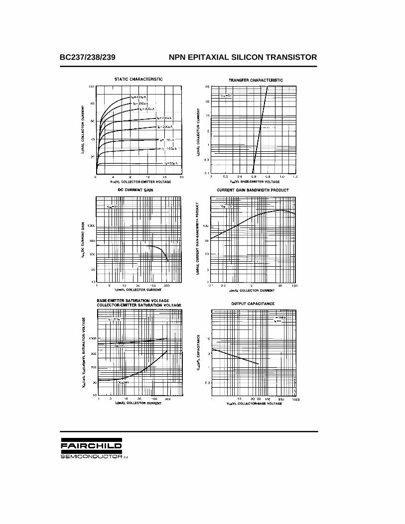
BC237/238/239 NPN EPITAXIAL SILICON TRANSISTOR

TRADEMARKS
ACEx™CoolFET™CROSSVOLT™E2CMOSTM
FACT™FACT Quiet Series™FAST®
FASTr™GTO™HiSeC™
The following are registered and unregistered trademarks Fairchild Semiconductor owns or is authorized to use and isnot intended to be an exhaustive list of all such trademarks.
LIFE SUPPORT POLICY
FAIRCHILD’S PRODUCTS ARE NOT AUTHORIZED FOR USE AS CRITICAL COMPONENTS IN LIFE SUPPORTDEVICES OR SYSTEMS WITHOUT THE EXPRESS WRITTEN APPROVAL OF FAIRCHILD SEMICONDUCTOR CORPORATION.As used herein:
ISOPLANAR™MICROWIRE™POP™PowerTrench™QS™Quiet Series™SuperSOT™-3SuperSOT™-6SuperSOT™-8TinyLogic™
1. Life support devices or systems are devices orsystems which, (a) are intended for surgical implant intothe body, or (b) support or sustain life, or (c) whosefailure to perform when properly used in accordancewith instructions for use provided in the labeling, can bereasonably expected to result in significant injury to theuser.
2. A critical component is any component of a lifesupport device or system whose failure to perform canbe reasonably expected to cause the failure of the lifesupport device or system, or to affect its safety oreffectiveness.
PRODUCT STATUS DEFINITIONS
Definition of Terms
Datasheet Identification Product Status Definition
Advance Information
Preliminary
No Identification Needed
Obsolete
This datasheet contains the design specifications forproduct development. Specifications may change inany manner without notice.
This datasheet contains preliminary data, andsupplementary data will be published at a later date.Fairchild Semiconductor reserves the right to makechanges at any time without notice in order to improvedesign.
This datasheet contains final specifications. FairchildSemiconductor reserves the right to make changes atany time without notice in order to improve design.
This datasheet contains specifications on a productthat has been discontinued by Fairchild semiconductor.The datasheet is printed for reference information only.
Formative orIn Design
First Production
Full Production
Not In Production
DISCLAIMER
FAIRCHILD SEMICONDUCTOR RESERVES THE RIGHT TO MAKE CHANGES WITHOUT FURTHERNOTICE TO ANY PRODUCTS HEREIN TO IMPROVE RELIABILITY, FUNCTION OR DESIGN. FAIRCHILDDOES NOT ASSUME ANY LIABILITY ARISING OUT OF THE APPLICATION OR USE OF ANY PRODUCTOR CIRCUIT DESCRIBED HEREIN; NEITHER DOES IT CONVEY ANY LICENSE UNDER ITS PATENTRIGHTS, NOR THE RIGHTS OF OTHERS.
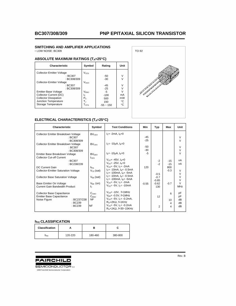
BC307/308/309 PNP EPITAXIAL SILICON TRANSISTOR
SWITCHING AND AMPLIFIER APPLICATIONS• LOW NOISE: BC309
ABSOLUTE MAXIMUM RATINGS (TA=25°°C)
ELECTRICAL CHARACTERISTICS (TA=25°°C)
hFE CLASSIFICATION
Characteristic Symbol Rating Unit
Collector-Emitter Voltage : BC307
: BC308/309Collector-Emitter Voltage
: BC307: BC308/309
Emitter-Base VoltageCollector Current (DC)Collector DissipationJunction TemperatureStorage Temperature
VCES
VCEO
VEBO
ICPC
TJ
TSTG
-50-30
-45-25-5
-100500150
-55 ~ 150
VV
VVV
mAmW°C°C
Characteristic Symbol Test Conditions Min Typ Max Unit
Collector Emitter Breakdown Voltage: BC307: BC308/309
Collector Emitter Breakdown Voltage : BC307: BC308/309
Emitter Base Breakdown VoltageCollector Cut-off Current
: BC307: BC238/239
DC Current GainCollector-Emitter Saturation Voltage
Collector Base Saturation Voltage
Base Emitter On VoltageCurrent Gain Bandwidth Product
Collector Base CapacitanceEmitter Base CapacitanceNoise Figure : BC237/238
: BC239 : BC239
BVCEO
BVCES
BVEBO
ICES
hFE
VCE (sat)
VBE (sat)
VBE (on)fT
CCBO
CEBO
NF
NF
IC= -2mA, IB=0
IC= -10µA, IB=0
IE= -10µA, IB=0
VCE= -45V, IB=0VCE= -25V, IB=0VCE= -5V, IC= -2mAIC= -10mA, IB= -0.5mAIC= -100mA, IB= -5mAIC= -10mA, IB= -0.5mAIC= -100mA, IB= -5mAVCE= -5V, IC= -2mAVCE= -5V, IC= -10mA
VCB= -10V, f=1MHzVEB= -0.5V, f=1MHzVCE= -5V, IC= -0.2mA,RG=2KΩ, f=1KHzVCE= -5V, IC= -0.2mARG=2KΩ, f=30~15KHz
-45-25
-50-30-5
120
-0.55
-2-2
-0.5-0.7
-0.85-0.62
130
12
2
-15-15800-0.3
-0.7
6
1044
VV
VVV
nAnA
VVVVV
MHz
pFpFdBdBdB
Classification A B C
hFE 120-220 180-460 380-800
TO-92
1999 Fairchild Semiconductor Corporation
Rev. B
BC307/308/309 PNP EPITAXIAL SILICON TRANSISTOR

TRADEMARKS
ACEx™CoolFET™CROSSVOLT™E2CMOSTM
FACT™FACT Quiet Series™FAST®
FASTr™GTO™HiSeC™
The following are registered and unregistered trademarks Fairchild Semiconductor owns or is authorized to use and isnot intended to be an exhaustive list of all such trademarks.
LIFE SUPPORT POLICY
FAIRCHILD’S PRODUCTS ARE NOT AUTHORIZED FOR USE AS CRITICAL COMPONENTS IN LIFE SUPPORTDEVICES OR SYSTEMS WITHOUT THE EXPRESS WRITTEN APPROVAL OF FAIRCHILD SEMICONDUCTOR CORPORATION.As used herein:
ISOPLANAR™MICROWIRE™POP™PowerTrench™QS™Quiet Series™SuperSOT™-3SuperSOT™-6SuperSOT™-8TinyLogic™
1. Life support devices or systems are devices orsystems which, (a) are intended for surgical implant intothe body, or (b) support or sustain life, or (c) whosefailure to perform when properly used in accordancewith instructions for use provided in the labeling, can bereasonably expected to result in significant injury to theuser.
2. A critical component is any component of a lifesupport device or system whose failure to perform canbe reasonably expected to cause the failure of the lifesupport device or system, or to affect its safety oreffectiveness.
PRODUCT STATUS DEFINITIONS
Definition of Terms
Datasheet Identification Product Status Definition
Advance Information
Preliminary
No Identification Needed
Obsolete
This datasheet contains the design specifications forproduct development. Specifications may change inany manner without notice.
This datasheet contains preliminary data, andsupplementary data will be published at a later date.Fairchild Semiconductor reserves the right to makechanges at any time without notice in order to improvedesign.
This datasheet contains final specifications. FairchildSemiconductor reserves the right to make changes atany time without notice in order to improve design.
This datasheet contains specifications on a productthat has been discontinued by Fairchild semiconductor.The datasheet is printed for reference information only.
Formative orIn Design
First Production
Full Production
Not In Production
DISCLAIMER
FAIRCHILD SEMICONDUCTOR RESERVES THE RIGHT TO MAKE CHANGES WITHOUT FURTHERNOTICE TO ANY PRODUCTS HEREIN TO IMPROVE RELIABILITY, FUNCTION OR DESIGN. FAIRCHILDDOES NOT ASSUME ANY LIABILITY ARISING OUT OF THE APPLICATION OR USE OF ANY PRODUCTOR CIRCUIT DESCRIBED HEREIN; NEITHER DOES IT CONVEY ANY LICENSE UNDER ITS PATENTRIGHTS, NOR THE RIGHTS OF OTHERS.
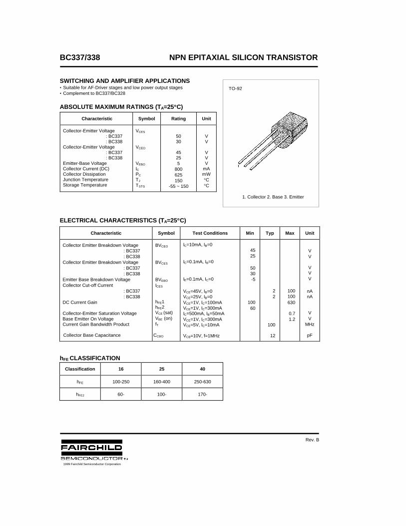
BC327/328 PNP EPITAXIAL SILICON TRANSISTOR
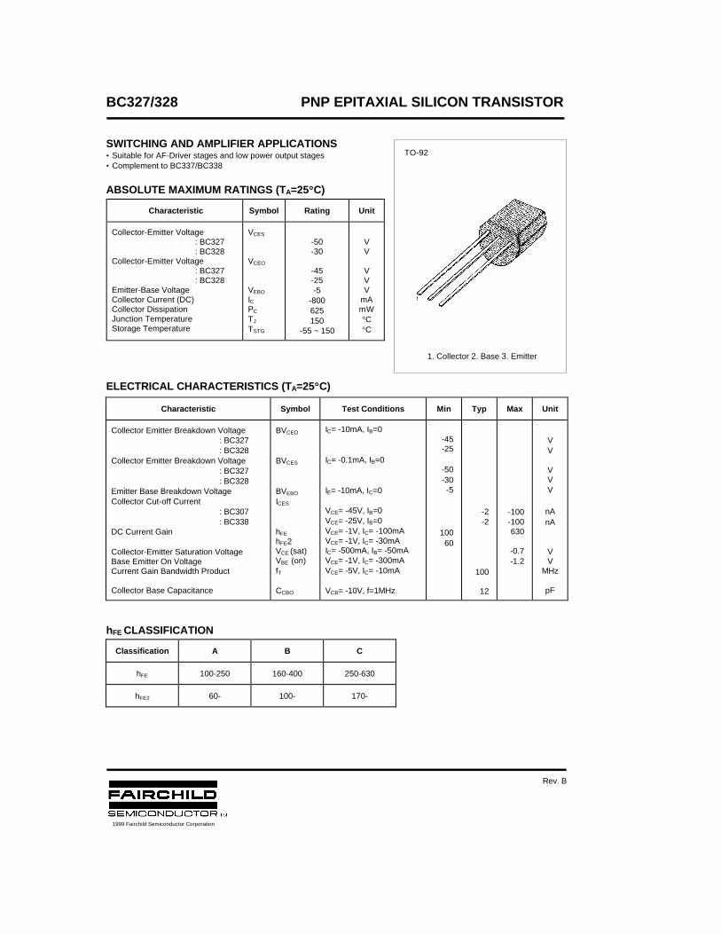
SWITCHING AND AMPLIFIER APPLICATIONS• Suitable for AF-Driver stages and low power output stages• Complement to BC337/BC338
ABSOLUTE MAXIMUM RATINGS (TA=25°°C)
ELECTRICAL CHARACTERISTICS (TA=25°°C)
hFE CLASSIFICATION
Characteristic Symbol Rating Unit
Collector-Emitter Voltage: BC327: BC328
Collector-Emitter Voltage: BC327: BC328
Emitter-Base VoltageCollector Current (DC)Collector DissipationJunction TemperatureStorage Temperature
VCES
VCEO
VEBO
ICPC
TJ
TSTG
-50-30
-45-25-5
-800625150
-55 ~ 150
VV
VVV
mAmW°C°C
Characteristic Symbol Test Conditions Min Typ Max Unit
Collector Emitter Breakdown Voltage: BC327: BC328
Collector Emitter Breakdown Voltage: BC327: BC328
Emitter Base Breakdown VoltageCollector Cut-off Current
: BC307: BC338
DC Current Gain
Collector-Emitter Saturation VoltageBase Emitter On VoltageCurrent Gain Bandwidth Product
Collector Base Capacitance
BVCEO
BVCES
BVEBO
ICES
hFE
hFE2VCE (sat)VBE (on)fT
CCBO
IC= -10mA, IB=0
IC= -0.1mA, IB=0
IE= -10mA, IC=0
VCE= -45V, IB=0VCE= -25V, IB=0VCE= -1V, IC= -100mAVCE= -1V, IC= -30mAIC= -500mA, IB= -50mAVCE= -1V, IC= -300mAVCE= -5V, IC= -10mA
VCB= -10V, f=1MHz
-45-25
-50-30-5
10060
-2-2
100
12
-100-100630
-0.7-1.2
VV
VVV
nAnA
VV
MHz
pF
Classification A B C
hFE 100-250 160-400 250-630
hFE2 60- 100- 170-
TO-92
1. Collector 2. Base 3. Emitter
1999 Fairchild Semiconductor Corporation
Rev. B
BC327/328 PNP EPITAXIAL SILICON TRANSISTOR
BC327/328 PNP EPITAXIAL SILICON TRANSISTOR

TRADEMARKS
ACEx™CoolFET™CROSSVOLT™E2CMOSTM
FACT™FACT Quiet Series™FAST®
FASTr™GTO™HiSeC™
The following are registered and unregistered trademarks Fairchild Semiconductor owns or is authorized to use and isnot intended to be an exhaustive list of all such trademarks.
LIFE SUPPORT POLICY
FAIRCHILD’S PRODUCTS ARE NOT AUTHORIZED FOR USE AS CRITICAL COMPONENTS IN LIFE SUPPORTDEVICES OR SYSTEMS WITHOUT THE EXPRESS WRITTEN APPROVAL OF FAIRCHILD SEMICONDUCTOR CORPORATION.As used herein:
ISOPLANAR™MICROWIRE™POP™PowerTrench™QS™Quiet Series™SuperSOT™-3SuperSOT™-6SuperSOT™-8TinyLogic™
1. Life support devices or systems are devices orsystems which, (a) are intended for surgical implant intothe body, or (b) support or sustain life, or (c) whosefailure to perform when properly used in accordancewith instructions for use provided in the labeling, can bereasonably expected to result in significant injury to theuser.
2. A critical component is any component of a lifesupport device or system whose failure to perform canbe reasonably expected to cause the failure of the lifesupport device or system, or to affect its safety oreffectiveness.
PRODUCT STATUS DEFINITIONS
Definition of Terms
Datasheet Identification Product Status Definition
Advance Information
Preliminary
No Identification Needed
Obsolete
This datasheet contains the design specifications forproduct development. Specifications may change inany manner without notice.
This datasheet contains preliminary data, andsupplementary data will be published at a later date.Fairchild Semiconductor reserves the right to makechanges at any time without notice in order to improvedesign.
This datasheet contains final specifications. FairchildSemiconductor reserves the right to make changes atany time without notice in order to improve design.
This datasheet contains specifications on a productthat has been discontinued by Fairchild semiconductor.The datasheet is printed for reference information only.
Formative orIn Design
First Production
Full Production
Not In Production
DISCLAIMER
FAIRCHILD SEMICONDUCTOR RESERVES THE RIGHT TO MAKE CHANGES WITHOUT FURTHERNOTICE TO ANY PRODUCTS HEREIN TO IMPROVE RELIABILITY, FUNCTION OR DESIGN. FAIRCHILDDOES NOT ASSUME ANY LIABILITY ARISING OUT OF THE APPLICATION OR USE OF ANY PRODUCTOR CIRCUIT DESCRIBED HEREIN; NEITHER DOES IT CONVEY ANY LICENSE UNDER ITS PATENTRIGHTS, NOR THE RIGHTS OF OTHERS.
BC
337-16 / BC
337-25Discrete POWER & Signal
Technologies
NPN General Purpose Amplifier
BC337-16BC337-25
This device is designed for use as general purpose amplifiersand switches requiring collector currents to 500 mA. Sourced fromProcess 12. See TN3019A for characteristics.
Absolute Maximum Ratings* TA = 25°C unless otherwise noted
*These ratings are limiting values above which the serviceability of any semiconductor device may be impaired.
NOTES:1) These ratings are based on a maximum junction temperature of 150 degrees C.2) These are steady state limits. The factory should be consulted on applications involving pulsed or low duty cycle operations.
Thermal Characteristics TA = 25°C unless otherwise noted
Symbol Parameter Value UnitsVCEO Collector-Emitter Voltage 45 V
VCES Collector-Base Voltage 50 V
VEBO Emitter-Base Voltage 5.0 V
IC Collector Current - Continuous 1.0 A
TJ, Tstg Operating and Storage Junction Temperature Range -55 to +150 °C
Symbol Characteristic Max UnitsBC337-16 / BC337-25
PD Total Device DissipationDerate above 25°C
6255.0
mWmW/°C
RθJC Thermal Resistance, Junction to Case 83.3 °C/W
RθJA Thermal Resistance, Junction to Ambient 200 °C/W
EB C
TO-92
1997 Fairchild Semiconductor Corporation 33716-25, Rev B
BC
337-16 / BC
337-25NPN General Purpose Amplifier
(continued)
Electrical Characteristics TA = 25°C unless otherwise noted
OFF CHARACTERISTICS
Symbol Parameter Test C onditions Min Max Units
V(BR)CEO Collector-Emitter BreakdownVoltage
IC = 10 mA, IB = 0 45 V
V(BR)CES Collector-Base Breakdown Voltage IC = 100 µA, IE = 0 50 V
V(BR)EBO Emitter-Base Breakdown Voltage IE = 100 µA, IC = 0 5.0 V
ICBO Collector Cutoff Current VCB = 20 V, IE = 0, TA = +25 °CVCB = 20 V, IE = 0, TA = +150°C
1005.0
nAµA
IEBO Emitter Cutoff Current VEB = 5.0 V, IC = 0 10 µA
ON CHARACTERISTICShFE DC Current Gain VCE = 1.0 V, IC = 100 mA
337-16337-25
VCE = 1.0 V, IC = 500 mA
10016040
250400
VCE(sat) Collector-Emitter Saturation Voltage IC = 500 mA, IB = 50 mA 0.7 V
VBE(on) Base-Emitter On Voltage VCE = 1.0 V, IC = 500 mA 1.2 V
BC337/338 NPN EPITAXIAL SILICON TRANSISTOR
SWITCHING AND AMPLIFIER APPLICATIONS• Suitable for AF-Driver stages and low power output stages• Complement to BC337/BC328
ABSOLUTE MAXIMUM RATINGS (TA=25°°C)
ELECTRICAL CHARACTERISTICS (TA=25°°C)
hFE CLASSIFICATION
Characteristic Symbol Rating Unit
Collector-Emitter Voltage: BC337: BC338
Collector-Emitter Voltage: BC337: BC338
Emitter-Base VoltageCollector Current (DC)Collector DissipationJunction TemperatureStorage Temperature
VCES
VCEO
VEBO
ICPC
TJ
TSTG
5030
45255
800625150
-55 ~ 150
VV
VVV
mAmW°C°C
Characteristic Symbol Test Conditions Min Typ Max Unit
Collector Emitter Breakdown Voltage: BC337: BC338
Collector Emitter Breakdown Voltage: BC337: BC338
Emitter Base Breakdown VoltageCollector Cut-off Current
: BC337: BC338
DC Current Gain
Collector-Emitter Saturation VoltageBase Emitter On VoltageCurrent Gain Bandwidth Product
Collector Base Capacitance
BVCEO
BVCES
BVEBO
ICES
hFE1hFE2VCE (sat)VBE (on)fT
CCBO
IC=10mA, IB=0
IC=0.1mA, IB=0
IE=0.1mA, IC=0
VCE=45V, IB=0VCE=25V, IB=0VCE=1V, IC=100mAVCE=1V, IC=300mAIC=500mA, IB=50mAVCE=1V, IC=300mAVCE=5V, IC=10mA
VCB=10V, f=1MHz
4525
5030-5
10060
22
100
12
100100630
0.71.2
VV
VVV
nAnA
VV
MHz
pF
Classification 16 25 40
hFE 100-250 160-400 250-630
hFE2 60- 100- 170-
TO-92
1. Collector 2. Base 3. Emitter
1999 Fairchild Semiconductor Corporation
Rev. B

TRADEMARKS
ACEx™CoolFET™CROSSVOLT™E2CMOSTM
FACT™FACT Quiet Series™FAST®
FASTr™GTO™HiSeC™
The following are registered and unregistered trademarks Fairchild Semiconductor owns or is authorized to use and isnot intended to be an exhaustive list of all such trademarks.
LIFE SUPPORT POLICY
FAIRCHILD’S PRODUCTS ARE NOT AUTHORIZED FOR USE AS CRITICAL COMPONENTS IN LIFE SUPPORTDEVICES OR SYSTEMS WITHOUT THE EXPRESS WRITTEN APPROVAL OF FAIRCHILD SEMICONDUCTOR CORPORATION.As used herein:
ISOPLANAR™MICROWIRE™POP™PowerTrench™QS™Quiet Series™SuperSOT™-3SuperSOT™-6SuperSOT™-8TinyLogic™
1. Life support devices or systems are devices orsystems which, (a) are intended for surgical implant intothe body, or (b) support or sustain life, or (c) whosefailure to perform when properly used in accordancewith instructions for use provided in the labeling, can bereasonably expected to result in significant injury to theuser.
2. A critical component is any component of a lifesupport device or system whose failure to perform canbe reasonably expected to cause the failure of the lifesupport device or system, or to affect its safety oreffectiveness.
PRODUCT STATUS DEFINITIONS
Definition of Terms
Datasheet Identification Product Status Definition
Advance Information
Preliminary
No Identification Needed
Obsolete
This datasheet contains the design specifications forproduct development. Specifications may change inany manner without notice.
This datasheet contains preliminary data, andsupplementary data will be published at a later date.Fairchild Semiconductor reserves the right to makechanges at any time without notice in order to improvedesign.
This datasheet contains final specifications. FairchildSemiconductor reserves the right to make changes atany time without notice in order to improve design.
This datasheet contains specifications on a productthat has been discontinued by Fairchild semiconductor.The datasheet is printed for reference information only.
Formative orIn Design
First Production
Full Production
Not In Production
DISCLAIMER
FAIRCHILD SEMICONDUCTOR RESERVES THE RIGHT TO MAKE CHANGES WITHOUT FURTHERNOTICE TO ANY PRODUCTS HEREIN TO IMPROVE RELIABILITY, FUNCTION OR DESIGN. FAIRCHILDDOES NOT ASSUME ANY LIABILITY ARISING OUT OF THE APPLICATION OR USE OF ANY PRODUCTOR CIRCUIT DESCRIBED HEREIN; NEITHER DOES IT CONVEY ANY LICENSE UNDER ITS PATENTRIGHTS, NOR THE RIGHTS OF OTHERS.
BC
368
BC368
NPN General Purpose AmplifierThis device is designed for general purpose medium poweramplifiers and switches requiring collector currents to 1.5 A.Sourced from Process 37.
Absolute Maximum Ratings* TA = 25°C unless otherwise noted
*These ratings are limiting values above which the serviceability of any semiconductor device may be impaired.
NOTES:1) These ratings are based on a maximum junction temperature of 150 degrees C.2) These are steady state limits. The factory should be consulted on applications involving pulsed or low duty cycle operations
Thermal Characteristic s TA = 25°C unless otherwise noted
Symbol Characteristic Max UnitsBC368
PD Total Device DissipationDerate above 25°C
6255.0
mWmW/°C
RθJC Thermal Resistance, Junction to Case 83.3 °C/W
RθJA Thermal Resistance, Junction to Ambient 200 °C/W
BC
368
Symbol Parameter Value Units
VCEO Collector-Emitter Voltage 20 V
VCES Collector-Base Voltage 25 V
VEBO Emitter-Base Voltage 5.0 V
IC Collector Current - Continuous 2.0 A
TJ, Tstg Operating and Storage Junction Temperature Range -55 to +150 °C
BC E
TO-92
1997 Fairchild Semiconductor Corporation
BC
368
Electrical Characteristics TA = 25°C unless otherwise noted
OFF CHARACTERISTICS
Symbol Parameter Test Conditions Min Max Units
ON CHARACTERISTICShFE DC Current Gain IC = 5.0 mA, VCE = 10 V
IC = 0.5 A, VCE = 1.0 VIC = 1.0 A, VCE = 1.0 V
508560
375
VCE(sat) Collector-Emitter Saturation Voltage IC = 1.0 A, IB = 100 mA 0.5 V
VBE(on) Base-Emitter On Voltage IC = 1.0 A, VCE = 1.0 V 1.0 V
SMALL SIGNAL CHARACTERISTICSfT Current Gain - Bandwidth Product IC = 10 mA, VCE = 5.0 V,
f = 35 MHz45 MHz
V(BR)CEO Collector-Emitter Breakdown Voltage IC = 10 mA, IB = 0 20 V
V(BR)CES Collector-Base Breakdown Voltage IC = 100 µA, IE = 0 25 V
V(BR)EBO Emitter-Base Breakdown Voltage IE = 10 µA, IC = 0 5.0 V
ICBO Collector-Cutoff Current VCB = 25 V, IE = 0VCB = 25 V, IE = 0, TA = 150°C
101.0
µAmA
IEBO Emitter-Cutoff Current VEB = 5.0 V, IC = 0 10 µA
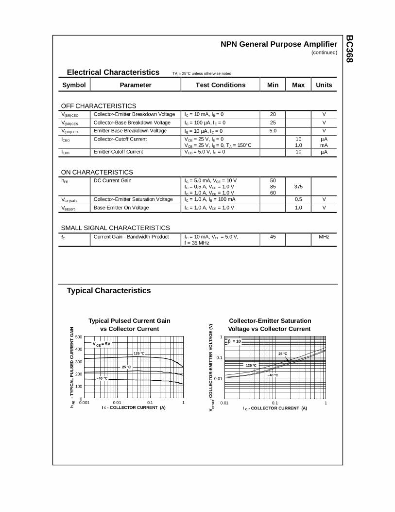
NPN General Purpose Amplifier(continued)
Typical Characteristics
Typical Pulsed Current Gainvs Collector Current
0.001 0.01 0.1 10
100
200
300
400
500
I - COLLECTOR CURRENT (A)h
- T
YP
ICA
L P
ULS
ED
CU
RR
EN
T G
AIN
FE
- 40 ºC
25 °C
C
V = 5VCE
125 °C
Collector-Emitter SaturationVoltage vs Collector Current
P 3
0.01 0.1 1
0.01
0.1
1
I - COLLECTOR CURRENT (A)V
-
CO
LLE
CTO
R-E
MIT
TE
R V
OLT
AG
E (
V)
CE
SAT
C
ββ = 10
125 ºC
- 40 ºC
25 °C
BC
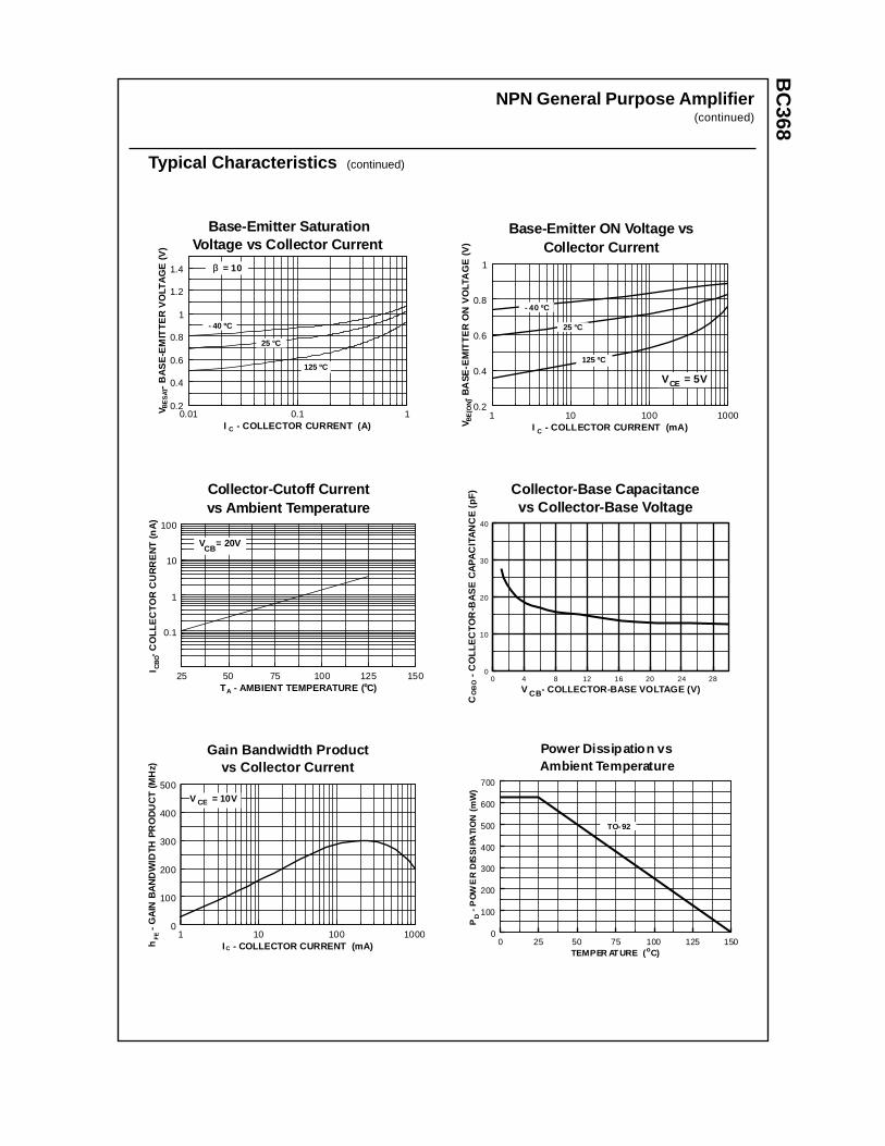
368NPN General Purpose Amplifier
(continued)
Typical Characteristics (continued)
Base-Emitter ON Voltage vsCollector Current
P 3
1 10 100 10000.2
0.4
0.6
0.8
1
I - COLLECTOR CURRENT (mA)V
-
BA
SE
-EM
ITT
ER
ON
VO
LTA
GE
(V
)B
E(O
N)
125 ºC
- 40 ºC
25 °C
C
V = 5VCE
Base-Emitter SaturationVoltage vs Collector Current
P 3
0.01 0.1 10.2
0.4
0.6
0.8
1
1.2
1.4
I - COLLECTOR CURRENT (A)
V
-
BA
SE
-EM
ITT
ER
VO
LTA
GE
(V
)B
ES
AT
C
ββ = 10
125 ºC
- 40 ºC
25 °C
Collector-Cutoff Currentvs Ambient Temperature
25 50 75 100 125 150
0.1
1
10
100
T - AMBIENT TEMPERATURE ( C)
I
- C
OLL
EC
TO
R C
UR
RE
NT
(n
A)
A
V = 20VCB
º
CB
O
Collector-Base Capacitancevs Collector-Base Voltage
Pr 37
0 4 8 12 16 20 24 280
10
20
30
40
V - COLLECTOR-BASE VOLTAGE (V)
C
-
CO
LLE
CT
OR
-BA
SE
CA
PA
CIT
AN
CE
(pF
)
CBOB
O
Gain Bandwidth Productvs Collector Current
1 10 100 10000
100
200
300
400
500
I - COLLECTOR CURRENT (mA)h
- G
AIN
BA
ND
WID
TH P
RO
DU
CT
(M
Hz)
C
FE
V = 10VCE
Power Dissipation vsAmbient Temperature
0 25 50 75 100 125 1500
100
200
300
400
500
600
700
TEMPER AT URE ( C)
P
- PO
WE
R D
ISS
IPA
TIO
N (
mW
)D
o
TO-92

TRADEMARKS
ACEx™CoolFET™CROSSVOLT™E2CMOSTM
FACT™FACT Quiet Series™FAST®
FASTr™GTO™HiSeC™
The following are registered and unregistered trademarks Fairchild Semiconductor owns or is authorized to use and isnot intended to be an exhaustive list of all such trademarks.
LIFE SUPPORT POLICY
FAIRCHILD’S PRODUCTS ARE NOT AUTHORIZED FOR USE AS CRITICAL COMPONENTS IN LIFE SUPPORTDEVICES OR SYSTEMS WITHOUT THE EXPRESS WRITTEN APPROVAL OF FAIRCHILD SEMICONDUCTOR CORPORATION.As used herein:
ISOPLANAR™MICROWIRE™POP™PowerTrench™QS™Quiet Series™SuperSOT™-3SuperSOT™-6SuperSOT™-8TinyLogic™
1. Life support devices or systems are devices orsystems which, (a) are intended for surgical implant intothe body, or (b) support or sustain life, or (c) whosefailure to perform when properly used in accordancewith instructions for use provided in the labeling, can bereasonably expected to result in significant injury to theuser.
2. A critical component is any component of a lifesupport device or system whose failure to perform canbe reasonably expected to cause the failure of the lifesupport device or system, or to affect its safety oreffectiveness.
PRODUCT STATUS DEFINITIONS
Definition of Terms
Datasheet Identification Product Status Definition
Advance Information
Preliminary
No Identification Needed
Obsolete
This datasheet contains the design specifications forproduct development. Specifications may change inany manner without notice.
This datasheet contains preliminary data, andsupplementary data will be published at a later date.Fairchild Semiconductor reserves the right to makechanges at any time without notice in order to improvedesign.
This datasheet contains final specifications. FairchildSemiconductor reserves the right to make changes atany time without notice in order to improve design.
This datasheet contains specifications on a productthat has been discontinued by Fairchild semiconductor.The datasheet is printed for reference information only.
Formative orIn Design
First Production
Full Production
Not In Production
DISCLAIMER
FAIRCHILD SEMICONDUCTOR RESERVES THE RIGHT TO MAKE CHANGES WITHOUT FURTHERNOTICE TO ANY PRODUCTS HEREIN TO IMPROVE RELIABILITY, FUNCTION OR DESIGN. FAIRCHILDDOES NOT ASSUME ANY LIABILITY ARISING OUT OF THE APPLICATION OR USE OF ANY PRODUCTOR CIRCUIT DESCRIBED HEREIN; NEITHER DOES IT CONVEY ANY LICENSE UNDER ITS PATENTRIGHTS, NOR THE RIGHTS OF OTHERS.
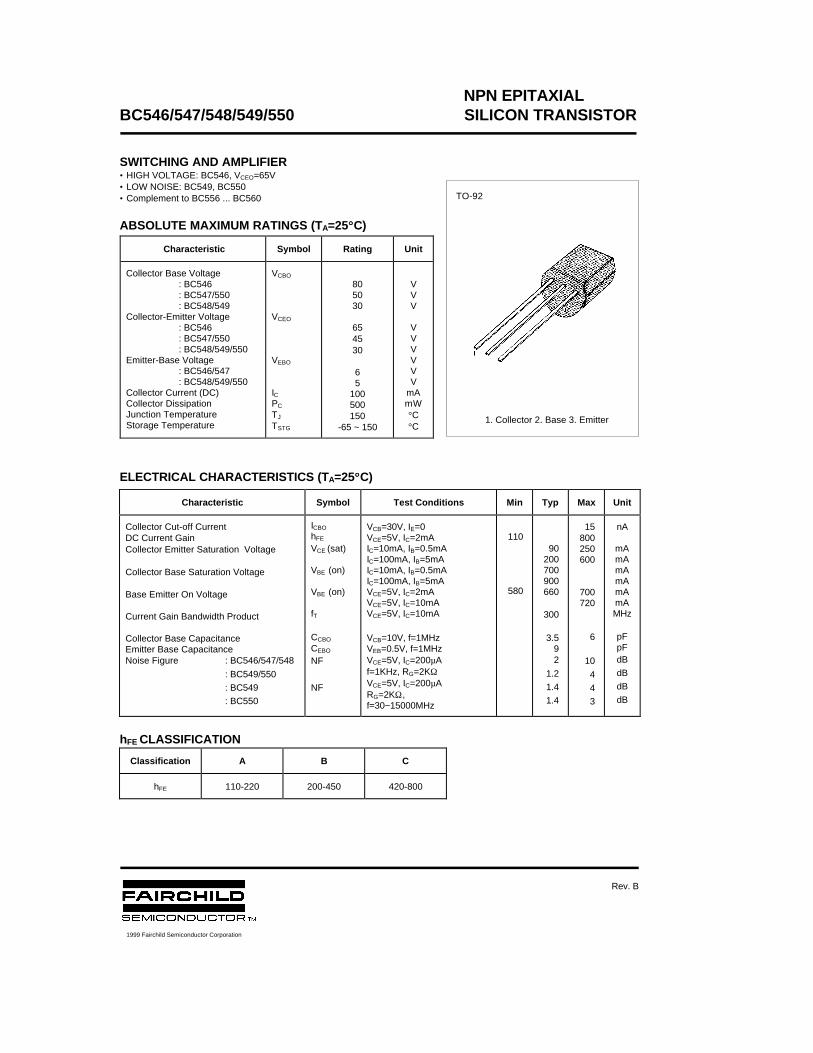
NPN EPITAXIALBC546/547/548/549/550 SILICON TRANSISTOR
SWITCHING AND AMPLIFIER• HIGH VOLTAGE: BC546, VCEO=65V• LOW NOISE: BC549, BC550• Complement to BC556 ... BC560
ABSOLUTE MAXIMUM RATINGS (TA=25°°C)
ELECTRICAL CHARACTERISTICS (TA=25°°C)
hFE CLASSIFICATION
Characteristic Symbol Rating Unit
Collector Base Voltage: BC546: BC547/550: BC548/549
Collector-Emitter Voltage: BC546: BC547/550: BC548/549/550
Emitter-Base Voltage: BC546/547: BC548/549/550
Collector Current (DC)Collector DissipationJunction TemperatureStorage Temperature
VCBO
VCEO
VEBO
ICPC
TJ
TSTG
805030
654530
65
100500150
-65 ~ 150
VVV
VVVVVV
mAmW°C°C
Characteristic Symbol Test Conditions Min Typ Max Unit
Collector Cut-off CurrentDC Current GainCollector Emitter Saturation Voltage
Collector Base Saturation Voltage
Base Emitter On Voltage
Current Gain Bandwidth Product
Collector Base CapacitanceEmitter Base CapacitanceNoise Figure : BC546/547/548
: BC549/550
: BC549
: BC550
ICBO
hFE
VCE (sat)
VBE (on)
VBE (on)
fT
CCBO
CEBO
NF
NF
VCB=30V, IE=0VCE=5V, IC=2mAIC=10mA, IB=0.5mAIC=100mA, IB=5mAIC=10mA, IB=0.5mAIC=100mA, IB=5mAVCE=5V, IC=2mAVCE=5V, IC=10mAVCE=5V, IC=10mA
VCB=10V, f=1MHzVEB=0.5V, f=1MHzVCE=5V, IC=200µAf=1KHz, RG=2KΩVCE=5V, IC=200µARG=2KΩ,f=30~15000MHz
110
580
90200700900660
300
3.592
1.2
1.4
1.4
15800250600
700720
6
10
4
4
3
nA
mAmAmAmAmAmAMHz
pFpFdB
dB
dB
dB
Classification A B C
hFE 110-220 200-450 420-800
TO-92
1. Collector 2. Base 3. Emitter
1999 Fairchild Semiconductor Corporation
Rev. B
NPN EPITAXIALBC546/547/548/549/550 SILICON TRANSISTOR

TRADEMARKS
ACEx™CoolFET™CROSSVOLT™E2CMOSTM
FACT™FACT Quiet Series™FAST®
FASTr™GTO™HiSeC™
The following are registered and unregistered trademarks Fairchild Semiconductor owns or is authorized to use and isnot intended to be an exhaustive list of all such trademarks.
LIFE SUPPORT POLICY
FAIRCHILD’S PRODUCTS ARE NOT AUTHORIZED FOR USE AS CRITICAL COMPONENTS IN LIFE SUPPORTDEVICES OR SYSTEMS WITHOUT THE EXPRESS WRITTEN APPROVAL OF FAIRCHILD SEMICONDUCTOR CORPORATION.As used herein:
ISOPLANAR™MICROWIRE™POP™PowerTrench™QS™Quiet Series™SuperSOT™-3SuperSOT™-6SuperSOT™-8TinyLogic™
1. Life support devices or systems are devices orsystems which, (a) are intended for surgical implant intothe body, or (b) support or sustain life, or (c) whosefailure to perform when properly used in accordancewith instructions for use provided in the labeling, can bereasonably expected to result in significant injury to theuser.
2. A critical component is any component of a lifesupport device or system whose failure to perform canbe reasonably expected to cause the failure of the lifesupport device or system, or to affect its safety oreffectiveness.
PRODUCT STATUS DEFINITIONS
Definition of Terms
Datasheet Identification Product Status Definition
Advance Information
Preliminary
No Identification Needed
Obsolete
This datasheet contains the design specifications forproduct development. Specifications may change inany manner without notice.
This datasheet contains preliminary data, andsupplementary data will be published at a later date.Fairchild Semiconductor reserves the right to makechanges at any time without notice in order to improvedesign.
This datasheet contains final specifications. FairchildSemiconductor reserves the right to make changes atany time without notice in order to improve design.
This datasheet contains specifications on a productthat has been discontinued by Fairchild semiconductor.The datasheet is printed for reference information only.
Formative orIn Design
First Production
Full Production
Not In Production
DISCLAIMER
FAIRCHILD SEMICONDUCTOR RESERVES THE RIGHT TO MAKE CHANGES WITHOUT FURTHERNOTICE TO ANY PRODUCTS HEREIN TO IMPROVE RELIABILITY, FUNCTION OR DESIGN. FAIRCHILDDOES NOT ASSUME ANY LIABILITY ARISING OUT OF THE APPLICATION OR USE OF ANY PRODUCTOR CIRCUIT DESCRIBED HEREIN; NEITHER DOES IT CONVEY ANY LICENSE UNDER ITS PATENTRIGHTS, NOR THE RIGHTS OF OTHERS.
BC
548 / BC
548A / B
C548B
/ BC
548CDiscrete POWER & Signal
Technologies
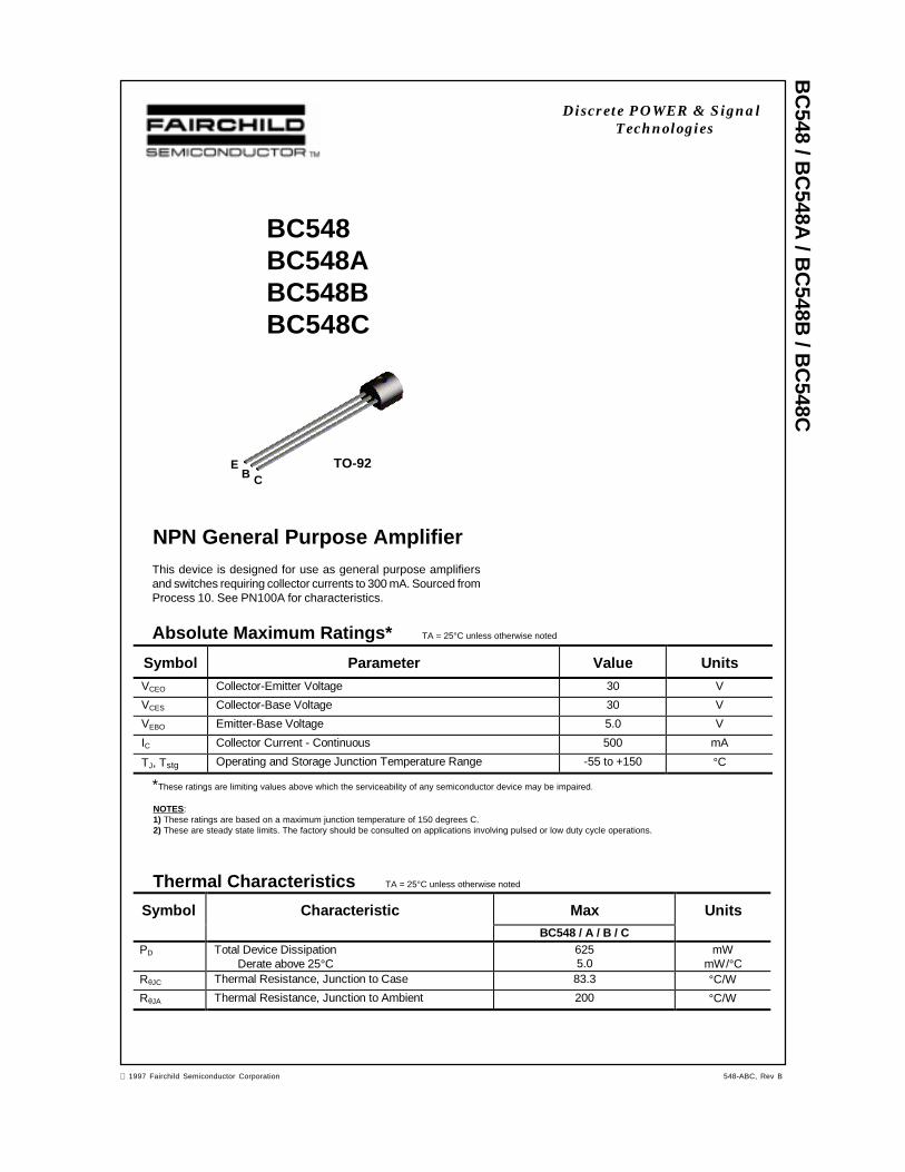
NPN General Purpose Amplifier
BC548BC548ABC548BBC548C
This device is designed for use as general purpose amplifiersand switches requiring collector currents to 300 mA. Sourced fromProcess 10. See PN100A for characteristics.
Absolute Maximum Ratings* TA = 25°C unless otherwise noted
*These ratings are limiting values above which the serviceability of any semiconductor device may be impaired.
NOTES:1) These ratings are based on a maximum junction temperature of 150 degrees C.2) These are steady state limits. The factory should be consulted on applications involving pulsed or low duty cycle operations.
Thermal Characteristics TA = 25°C unless otherwise noted
Symbol Parameter Value UnitsVCEO Collector-Emitter Voltage 30 V
VCES Collector-Base Voltage 30 V
VEBO Emitter-Base Voltage 5.0 V
IC Collector Current - Continuous 500 mA
TJ, Tstg Operating and Storage Junction Temperature Range -55 to +150 °C
Symbol Characteristic Max UnitsBC548 / A / B / C
PD Total Device DissipationDerate above 25°C
6255.0
mWmW/°C
RθJC Thermal Resistance, Junction to Case 83.3 °C/W
RθJA Thermal Resistance, Junction to Ambient 200 °C/W
EB C
TO-92
1997 Fairchild Semiconductor Corporation 548-ABC, Rev B
BC
548 / BC
548A / B
C548B
/ BC
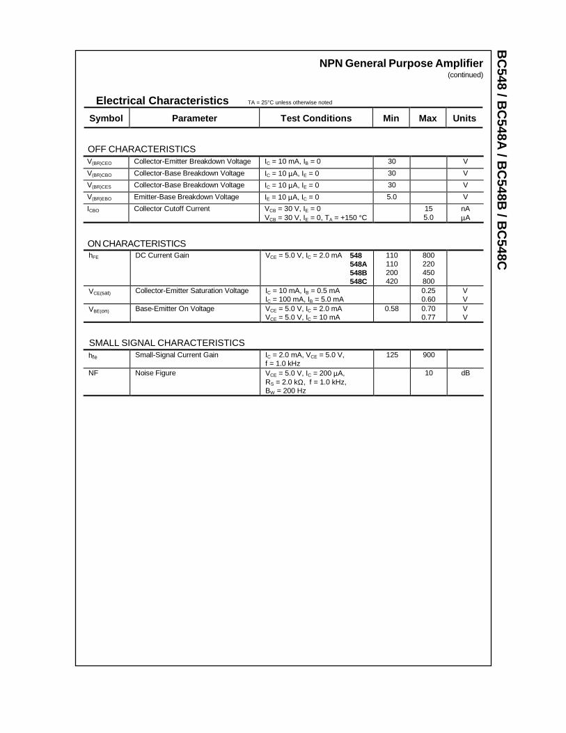
548CNPN General Purpose Amplifier
(continued)
Electrical Characteristics TA = 25°C unless otherwise noted
OFF CHARACTERISTICS
Symbol Parameter Test C onditions Min Max Units
V(BR)CEO Collector-Emitter Breakdown Voltage IC = 10 mA, IB = 0 30 V
V(BR)CBO Collector-Base Breakdown Voltage IC = 10 µA, IE = 0 30 V
V(BR)CES Collector-Base Breakdown Voltage IC = 10 µA, IE = 0 30 V
V(BR)EBO Emitter-Base Breakdown Voltage IE = 10 µA, IC = 0 5.0 V
ICBO Collector Cutoff Current VCB = 30 V, IE = 0VCB = 30 V, IE = 0, TA = +150 °C
155.0
nAµA
ON CHARACTERISTICShFE DC Current Gain VCE = 5.0 V, IC = 2.0 mA 548
548A 548B
548C
110110200420
800220450800
VCE(sat) Collector-Emitter Saturation Voltage IC = 10 mA, IB = 0.5 mAIC = 100 mA, IB = 5.0 mA
0.250.60
VV
VBE(on) Base-Emitter On Voltage VCE = 5.0 V, IC = 2.0 mAVCE = 5.0 V, IC = 10 mA
0.58 0.700.77
VV
SMALL SIGNAL CHARACTERISTICShfe Small-Signal Current Gain IC = 2.0 mA, VCE = 5.0 V,
f = 1.0 kHz125 900
NF Noise Figure VCE = 5.0 V, IC = 200 µA,RS = 2.0 kΩ, f = 1.0 kHz,BW = 200 Hz
10 dB
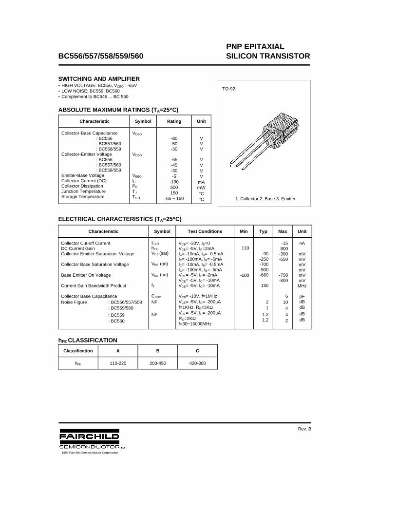
PNP EPITAXIALBC556/557/558/559/560 SILICON TRANSISTOR
SWITCHING AND AMPLIFIER• HIGH VOLTAGE: BC556, VCEO= -65V• LOW NOISE: BC559, BC560• Complement to BC546 ... BC 550
ABSOLUTE MAXIMUM RATINGS (TA=25°°C)
ELECTRICAL CHARACTERISTICS (TA=25°°C)
hFE CLASSIFICATION
Characteristic Symbol Rating Unit
Collector-Base Capacitance: BC556: BC557/560: BC558/559
Collector-Emitter Voltage: BC556: BC557/560: BC558/559
Emitter-Base VoltageCollector Current (DC)Collector DissipationJunction TemperatureStorage Temperature
VCBO
VCEO
VEBO
ICPC
TJ
TSTG
-80-50-30
-65-45-30-5
-100500150
-65 ~ 150
VVV
VVVV
mAmW°C°C
Characteristic Symbol Test Conditions Min Typ Max Unit
Collector Cut-off CurrentDC Current GainCollector Emitter Saturation Voltage
Collector Base Saturation Voltage
Base Emitter On Voltage
Current Gain Bandwidth Product
Collector Base CapacitanceNoise Figure : BC556/557/558 : BC559/560
: BC559 : BC560
ICBO
hFE
VCE (sat)
VBE (on)
VBE (on)
fT
CCBO
NF
NF
VCB= -30V, IE=0VCE= -5V, IC=2mAIC= -10mA, IB= -0.5mAIC= -100mA, IB= -5mAIC= -10mA, IB= -0.5mAIC= -100mA, IB= -5mAVCE= -5V, IC= -2mAVCE= -5V, IC= -10mAVCE= -5V, IC= -10mA
VCB= -10V, f=1MHzVCE= -5V, IC= -200µAf=1KHz, RG=2KΩVCE= -5V, IC= -200µARG=2KΩf=30~15000MHz
110
-600
-90-250-700-900-660
150
21
1.21.2
-15800
-300-650
-750-800
610442
nA
mVmVmVmVmVmVMHz
pFdBdB
dBdB
Classification A B C
hFE 110-220 200-450 420-800
TO-92
1. Collector 2. Base 3. Emitter
1999 Fairchild Semiconductor Corporation
Rev. B
PNP EPITAXIALBC556/557/558/559/560 SILICON TRANSISTOR

TRADEMARKS
ACEx™CoolFET™CROSSVOLT™E2CMOSTM
FACT™FACT Quiet Series™FAST®
FASTr™GTO™HiSeC™
The following are registered and unregistered trademarks Fairchild Semiconductor owns or is authorized to use and isnot intended to be an exhaustive list of all such trademarks.
LIFE SUPPORT POLICY
FAIRCHILD’S PRODUCTS ARE NOT AUTHORIZED FOR USE AS CRITICAL COMPONENTS IN LIFE SUPPORTDEVICES OR SYSTEMS WITHOUT THE EXPRESS WRITTEN APPROVAL OF FAIRCHILD SEMICONDUCTOR CORPORATION.As used herein:
ISOPLANAR™MICROWIRE™POP™PowerTrench™QS™Quiet Series™SuperSOT™-3SuperSOT™-6SuperSOT™-8TinyLogic™
1. Life support devices or systems are devices orsystems which, (a) are intended for surgical implant intothe body, or (b) support or sustain life, or (c) whosefailure to perform when properly used in accordancewith instructions for use provided in the labeling, can bereasonably expected to result in significant injury to theuser.
2. A critical component is any component of a lifesupport device or system whose failure to perform canbe reasonably expected to cause the failure of the lifesupport device or system, or to affect its safety oreffectiveness.
PRODUCT STATUS DEFINITIONS
Definition of Terms
Datasheet Identification Product Status Definition
Advance Information
Preliminary
No Identification Needed
Obsolete
This datasheet contains the design specifications forproduct development. Specifications may change inany manner without notice.
This datasheet contains preliminary data, andsupplementary data will be published at a later date.Fairchild Semiconductor reserves the right to makechanges at any time without notice in order to improvedesign.
This datasheet contains final specifications. FairchildSemiconductor reserves the right to make changes atany time without notice in order to improve design.
This datasheet contains specifications on a productthat has been discontinued by Fairchild semiconductor.The datasheet is printed for reference information only.
Formative orIn Design
First Production
Full Production
Not In Production
DISCLAIMER
FAIRCHILD SEMICONDUCTOR RESERVES THE RIGHT TO MAKE CHANGES WITHOUT FURTHERNOTICE TO ANY PRODUCTS HEREIN TO IMPROVE RELIABILITY, FUNCTION OR DESIGN. FAIRCHILDDOES NOT ASSUME ANY LIABILITY ARISING OUT OF THE APPLICATION OR USE OF ANY PRODUCTOR CIRCUIT DESCRIBED HEREIN; NEITHER DOES IT CONVEY ANY LICENSE UNDER ITS PATENTRIGHTS, NOR THE RIGHTS OF OTHERS.
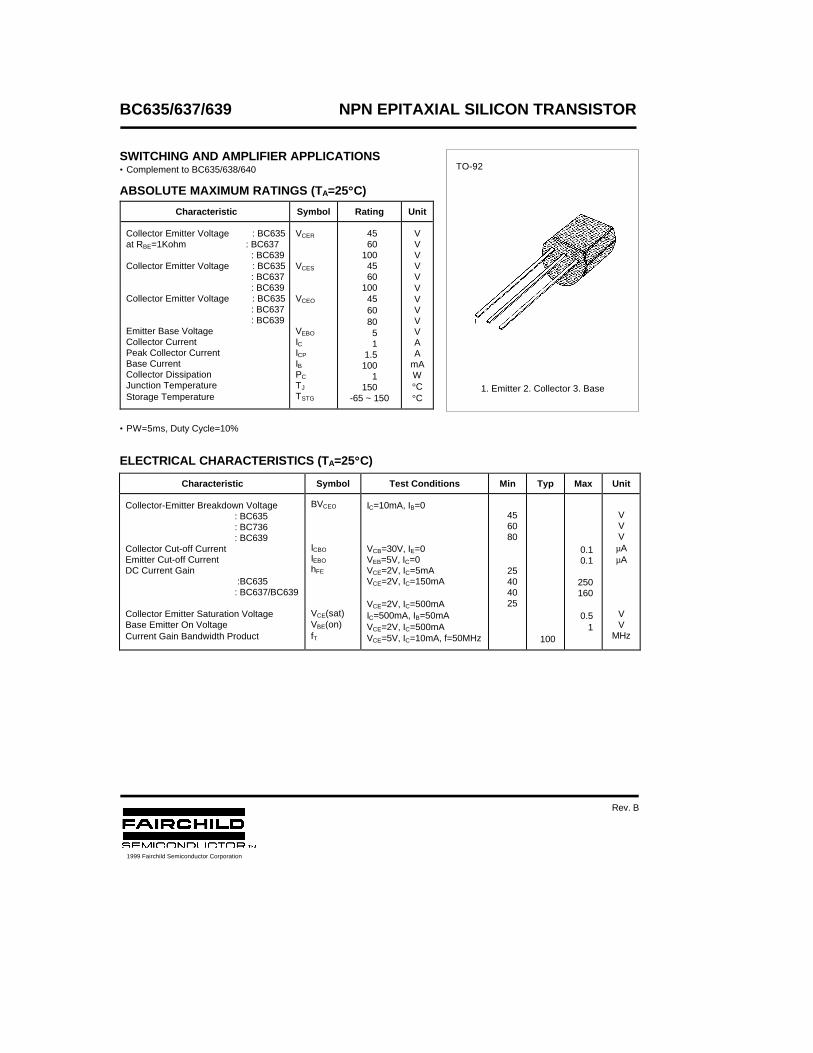
BC635/637/639 NPN EPITAXIAL SILICON TRANSISTOR
SWITCHING AND AMPLIFIER APPLICATIONS• Complement to BC635/638/640
ABSOLUTE MAXIMUM RATINGS (TA=25°°C)
• PW=5ms, Duty Cycle=10%
ELECTRICAL CHARACTERISTICS (TA=25°°C)
Characteristic Symbol Rating Unit
Collector Emitter Voltage : BC635at RBE=1Kohm : BC637 : BC639Collector Emitter Voltage : BC635 : BC637 : BC639Collector Emitter Voltage : BC635 : BC637 : BC639Emitter Base VoltageCollector CurrentPeak Collector CurrentBase CurrentCollector DissipationJunction TemperatureStorage Temperature
VCER
VCES
VCEO
VEBO
ICICP
IBPC
TJ
TSTG
45 60100 45 60100 45 60 80 5 1 1.5100 1150
-65 ~ 150
VVVVVVVVVVAA
mAW°C°C
Characteristic Symbol Test Conditions Min Typ Max Unit
Collector-Emitter Breakdown Voltage: BC635: BC736: BC639
Collector Cut-off CurrentEmitter Cut-off CurrentDC Current Gain
:BC635: BC637/BC639
Collector Emitter Saturation VoltageBase Emitter On VoltageCurrent Gain Bandwidth Product
BVCEO
ICBO
IEBO
hFE
VCE(sat)VBE(on)fT
IC=10mA, IB=0
VCB=30V, IE=0VEB=5V, IC=0VCE=2V, IC=5mAVCE=2V, IC=150mA
VCE=2V, IC=500mAIC=500mA, IB=50mAVCE=2V, IC=500mAVCE=5V, IC=10mA, f=50MHz
456080
25404025
100
0.10.1
250160
0.51
VVV
µAµA
VV
MHz
TO-92
1. Emitter 2. Collector 3. Base
1999 Fairchild Semiconductor Corporation
Rev. B
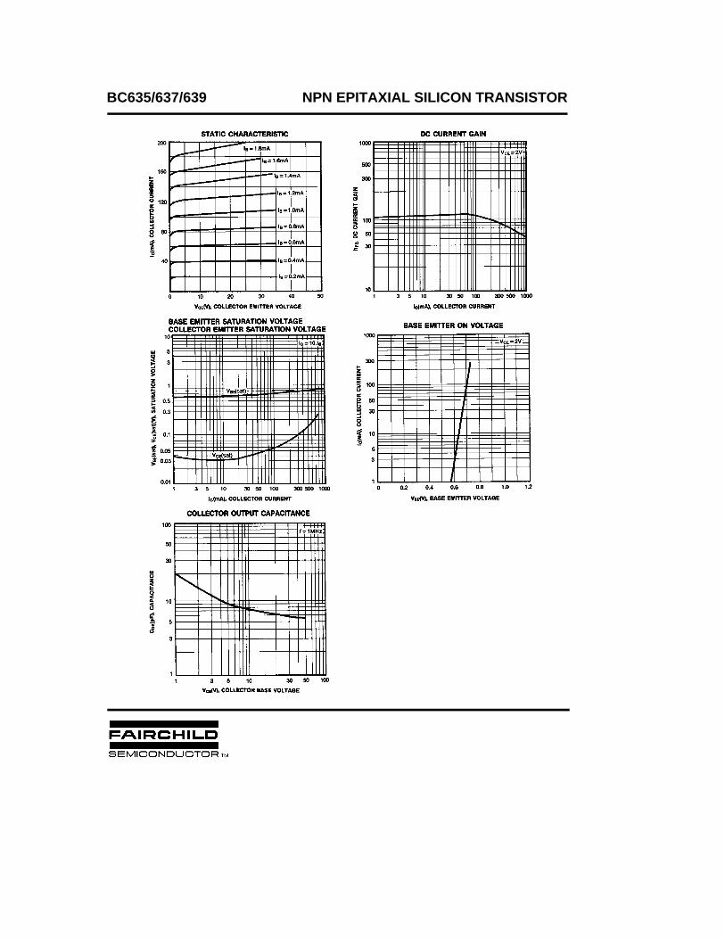
BC635/637/639 NPN EPITAXIAL SILICON TRANSISTOR

TRADEMARKS
ACEx™CoolFET™CROSSVOLT™E2CMOSTM
FACT™FACT Quiet Series™FAST®
FASTr™GTO™HiSeC™
The following are registered and unregistered trademarks Fairchild Semiconductor owns or is authorized to use and isnot intended to be an exhaustive list of all such trademarks.
LIFE SUPPORT POLICY
FAIRCHILD’S PRODUCTS ARE NOT AUTHORIZED FOR USE AS CRITICAL COMPONENTS IN LIFE SUPPORTDEVICES OR SYSTEMS WITHOUT THE EXPRESS WRITTEN APPROVAL OF FAIRCHILD SEMICONDUCTOR CORPORATION.As used herein:
ISOPLANAR™MICROWIRE™POP™PowerTrench™QS™Quiet Series™SuperSOT™-3SuperSOT™-6SuperSOT™-8TinyLogic™
1. Life support devices or systems are devices orsystems which, (a) are intended for surgical implant intothe body, or (b) support or sustain life, or (c) whosefailure to perform when properly used in accordancewith instructions for use provided in the labeling, can bereasonably expected to result in significant injury to theuser.
2. A critical component is any component of a lifesupport device or system whose failure to perform canbe reasonably expected to cause the failure of the lifesupport device or system, or to affect its safety oreffectiveness.
PRODUCT STATUS DEFINITIONS
Definition of Terms
Datasheet Identification Product Status Definition
Advance Information
Preliminary
No Identification Needed
Obsolete
This datasheet contains the design specifications forproduct development. Specifications may change inany manner without notice.
This datasheet contains preliminary data, andsupplementary data will be published at a later date.Fairchild Semiconductor reserves the right to makechanges at any time without notice in order to improvedesign.
This datasheet contains final specifications. FairchildSemiconductor reserves the right to make changes atany time without notice in order to improve design.
This datasheet contains specifications on a productthat has been discontinued by Fairchild semiconductor.The datasheet is printed for reference information only.
Formative orIn Design
First Production
Full Production
Not In Production
DISCLAIMER
FAIRCHILD SEMICONDUCTOR RESERVES THE RIGHT TO MAKE CHANGES WITHOUT FURTHERNOTICE TO ANY PRODUCTS HEREIN TO IMPROVE RELIABILITY, FUNCTION OR DESIGN. FAIRCHILDDOES NOT ASSUME ANY LIABILITY ARISING OUT OF THE APPLICATION OR USE OF ANY PRODUCTOR CIRCUIT DESCRIBED HEREIN; NEITHER DOES IT CONVEY ANY LICENSE UNDER ITS PATENTRIGHTS, NOR THE RIGHTS OF OTHERS.
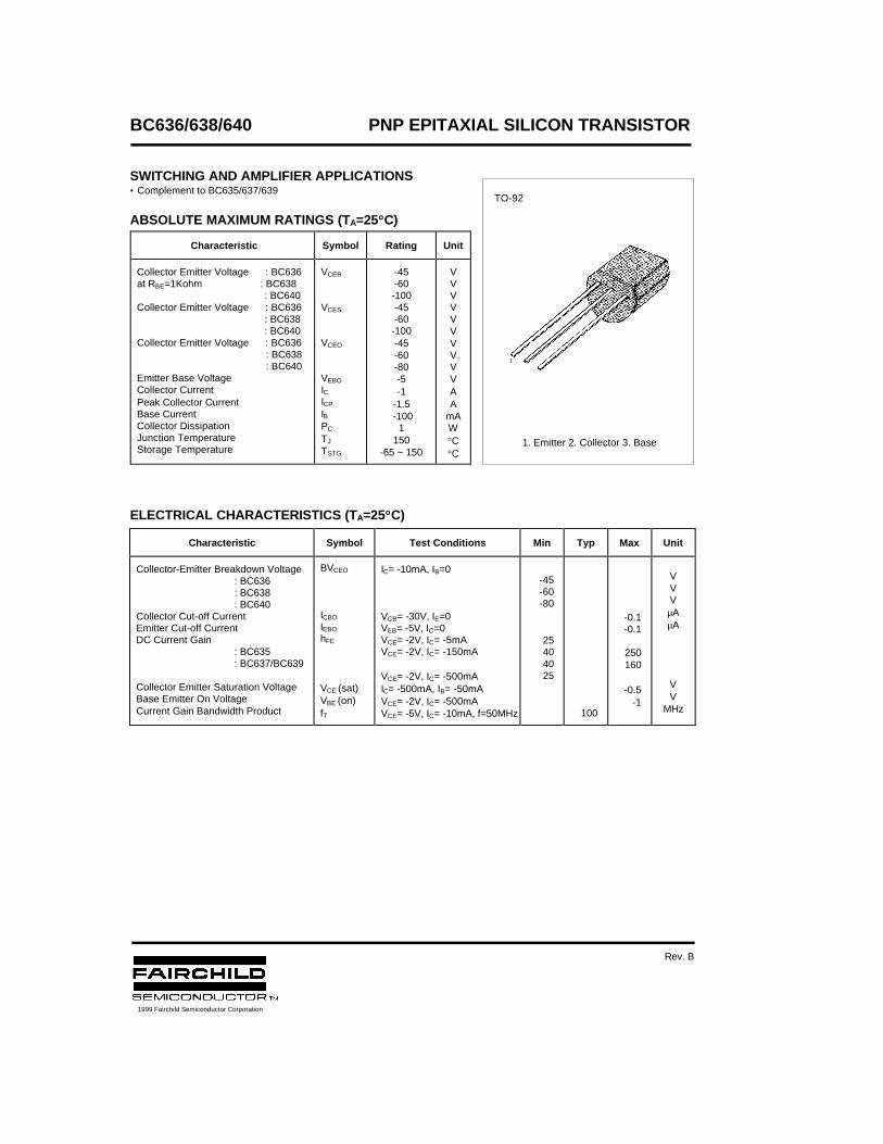
BC636/638/640 PNP EPITAXIAL SILICON TRANSISTOR
SWITCHING AND AMPLIFIER APPLICATIONS• Complement to BC635/637/639
ABSOLUTE MAXIMUM RATINGS (TA=25°°C)
ELECTRICAL CHARACTERISTICS (TA=25°°C)
Characteristic Symbol Rating Unit
Collector Emitter Voltage : BC636at RBE=1Kohm : BC638
: BC640Collector Emitter Voltage : BC636 : BC638 : BC640Collector Emitter Voltage : BC636
: BC638 : BC640Emitter Base VoltageCollector CurrentPeak Collector CurrentBase CurrentCollector DissipationJunction TemperatureStorage Temperature
VCER
VCES
VCEO
VEBO
ICICP
IBPC
TJ
TSTG
-45-60-100-45-60-100-45-60-80-5-1
-1.5 -100
1150
-65 ~ 150
VVVVVVVVVVAA
mAW°C°C
Characteristic Symbol Test Conditions Min Typ Max Unit
Collector-Emitter Breakdown Voltage: BC636: BC638: BC640
Collector Cut-off CurrentEmitter Cut-off CurrentDC Current Gain
: BC635: BC637/BC639
Collector Emitter Saturation VoltageBase Emitter On VoltageCurrent Gain Bandwidth Product
BVCEO
ICBO
IEBO
hFE
VCE (sat)VBE (on)fT
IC= -10mA, IB=0
VCB= -30V, IE=0VEB= -5V, IC=0VCE= -2V, IC= -5mAVCE= -2V, IC= -150mA
VCE= -2V, IC= -500mAIC= -500mA, IB= -50mAVCE= -2V, IC= -500mAVCE= -5V, IC= -10mA, f=50MHz
-45-60-80
25404025
100
-0.1-0.1
250160
-0.5-1
VVV
µAµA
VV
MHz
TO-92
1. Emitter 2. Collector 3. Base
1999 Fairchild Semiconductor Corporation
Rev. B
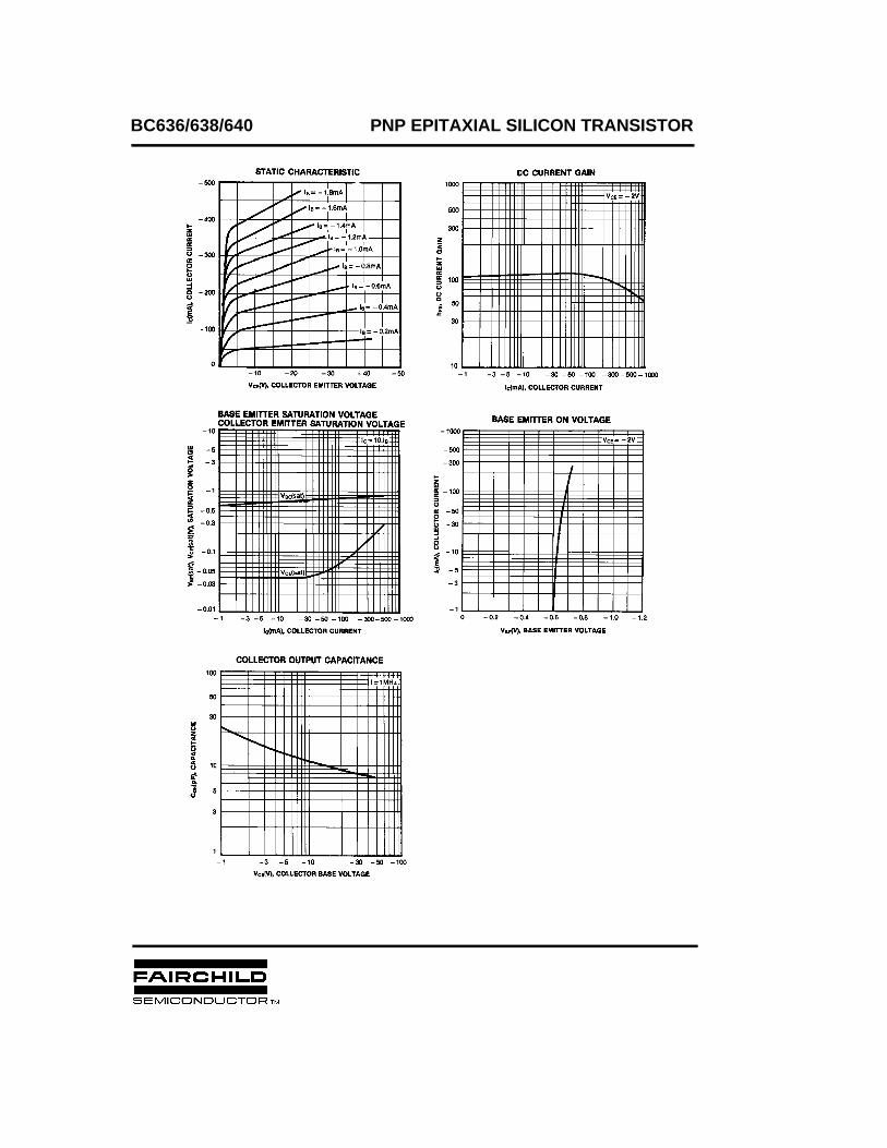
BC636/638/640 PNP EPITAXIAL SILICON TRANSISTOR

TRADEMARKS
ACEx™CoolFET™CROSSVOLT™E2CMOSTM
FACT™FACT Quiet Series™FAST®
FASTr™GTO™HiSeC™
The following are registered and unregistered trademarks Fairchild Semiconductor owns or is authorized to use and isnot intended to be an exhaustive list of all such trademarks.
LIFE SUPPORT POLICY
FAIRCHILD’S PRODUCTS ARE NOT AUTHORIZED FOR USE AS CRITICAL COMPONENTS IN LIFE SUPPORTDEVICES OR SYSTEMS WITHOUT THE EXPRESS WRITTEN APPROVAL OF FAIRCHILD SEMICONDUCTOR CORPORATION.As used herein:
ISOPLANAR™MICROWIRE™POP™PowerTrench™QS™Quiet Series™SuperSOT™-3SuperSOT™-6SuperSOT™-8TinyLogic™
1. Life support devices or systems are devices orsystems which, (a) are intended for surgical implant intothe body, or (b) support or sustain life, or (c) whosefailure to perform when properly used in accordancewith instructions for use provided in the labeling, can bereasonably expected to result in significant injury to theuser.
2. A critical component is any component of a lifesupport device or system whose failure to perform canbe reasonably expected to cause the failure of the lifesupport device or system, or to affect its safety oreffectiveness.
PRODUCT STATUS DEFINITIONS
Definition of Terms
Datasheet Identification Product Status Definition
Advance Information
Preliminary
No Identification Needed
Obsolete
This datasheet contains the design specifications forproduct development. Specifications may change inany manner without notice.
This datasheet contains preliminary data, andsupplementary data will be published at a later date.Fairchild Semiconductor reserves the right to makechanges at any time without notice in order to improvedesign.
This datasheet contains final specifications. FairchildSemiconductor reserves the right to make changes atany time without notice in order to improve design.
This datasheet contains specifications on a productthat has been discontinued by Fairchild semiconductor.The datasheet is printed for reference information only.
Formative orIn Design
First Production
Full Production
Not In Production
DISCLAIMER
FAIRCHILD SEMICONDUCTOR RESERVES THE RIGHT TO MAKE CHANGES WITHOUT FURTHERNOTICE TO ANY PRODUCTS HEREIN TO IMPROVE RELIABILITY, FUNCTION OR DESIGN. FAIRCHILDDOES NOT ASSUME ANY LIABILITY ARISING OUT OF THE APPLICATION OR USE OF ANY PRODUCTOR CIRCUIT DESCRIBED HEREIN; NEITHER DOES IT CONVEY ANY LICENSE UNDER ITS PATENTRIGHTS, NOR THE RIGHTS OF OTHERS.
BC
807-16 / BC
807-25 / BC
807-40
BC807-16BC807-25BC807-40
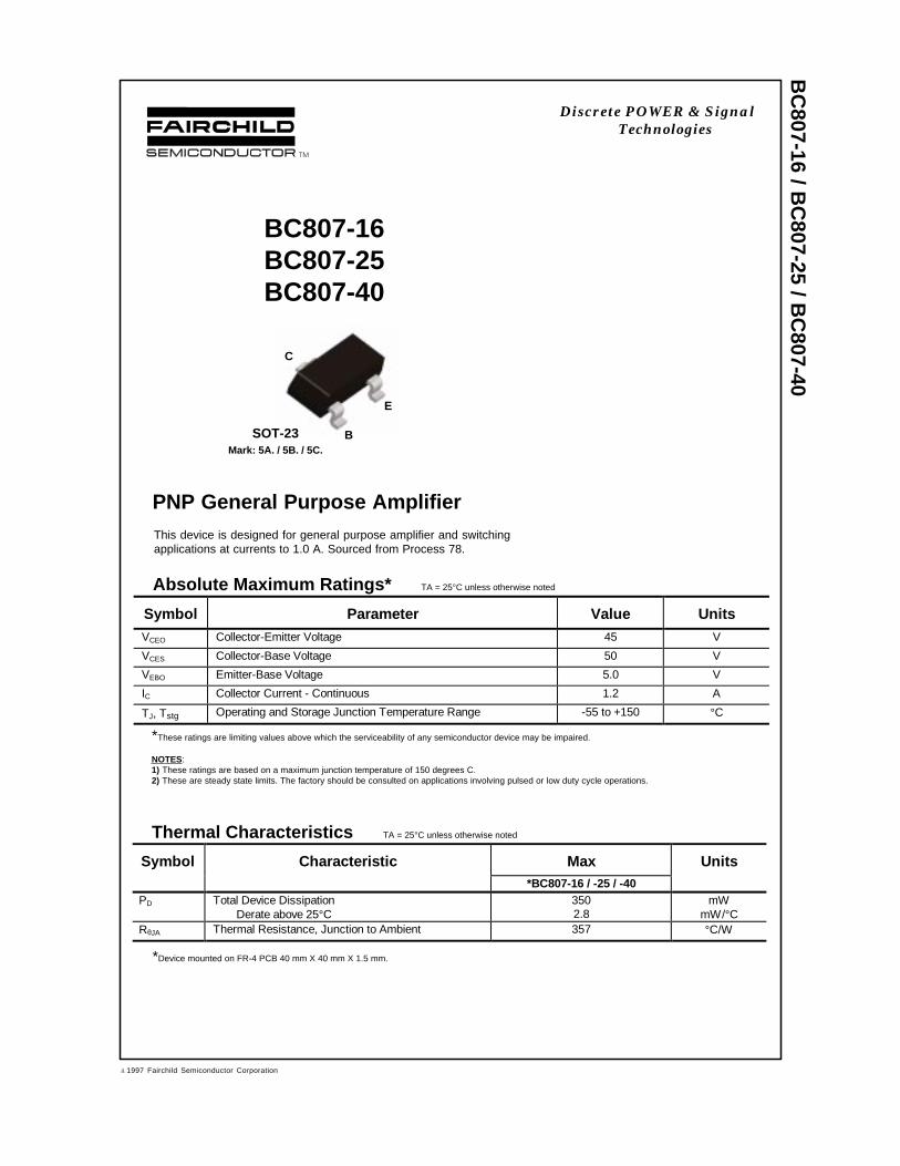
PNP General Purpose AmplifierThis device is designed for general purpose amplifier and switchingapplications at currents to 1.0 A. Sourced from Process 78.
Absolute Maximum Ratings* TA = 25°C unless otherwise noted
*These ratings are limiting values above which the serviceability of any semiconductor device may be impaired.
NOTES:1) These ratings are based on a maximum junction temperature of 150 degrees C.2) These are steady state limits. The factory should be consulted on applications involving pulsed or low duty cycle operations.
Thermal Characteristics TA = 25°C unless otherwise noted
Symbol Characteristic Max Units*BC807-16 / -25 / -40
PD Total Device DissipationDerate above 25°C
3502.8
mWmW/°C
RθJA Thermal Resistance, Junction to Ambient 357 °C/W
Symbol Parameter Value UnitsVCEO Collector-Emitter Voltage 45 V
VCES Collector-Base Voltage 50 V
VEBO Emitter-Base Voltage 5.0 V
IC Collector Current - Continuous 1.2 A
TJ, Tstg Operating and Storage Junction Temperature Range -55 to +150 °C
C
B
E
SOT-23Mark: 5A. / 5B. / 5C.
*Device mounted on FR-4 PCB 40 mm X 40 mm X 1.5 mm.
Discrete POWER & SignalTechnologies
ã 1997 Fairchild Semiconductor Corporation
BC
807-16 / BC
807-25 / BC
807-40
Electrical Characteristics TA = 25°C unless otherwise noted
OFF CHARACTERISTICS
Symbol Parameter Test C onditions Min Max Units
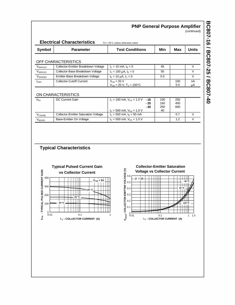
ON CHARACTERISTICShFE DC Current Gain IC = 100 mA, VCE = 1.0 V - 16
- 25- 40
IC = 500 mA, VCE = 1.0 V
10016025040
250400600
VCE(sat) Collector-Emitter Saturation Voltage IC = 500 mA, IB = 50 mA 0.7 V
VBE(on) Base-Emitter On Voltage IC = 500 mA, VCE = 1.0 V 1.2 V
V(BR)CEO Collector-Emitter Breakdown Voltage IC = 10 mA, IB = 0 45 V
V(BR)CES Collector-Base Breakdown Voltage IC = 100 µA, IE = 0 50 V
V(BR)EBO Emitter-Base Breakdown Voltage IE = 10 µA, IC = 0 5.0 V
ICBO Collector-Cutoff Current VCB = 20 VVCB = 20 V, TA = 150°C
1005.0
nAµA
PNP General Purpose Amplifier(continued)
Typical Characteristics
Collector-Emitter SaturationVoltage vs Collector Current
0.01 0.1 1 1.50
0.1
0.2
0.3
0.4
0.5
0.6
I - COLLECTOR CURRENT (A)V
-
CO
LLE
CTO
R-E
MIT
TE
R V
OLT
AG
E (
V)
CE
SAT
C
β = 10
125 ºC
- 40 ºC
25 °C
Typical Pulsed Current Gain
vs Collector Current
0.01 0.1 10
100
200
300
400
I - COLLECTOR CURRENT (A)h
- T
YP
ICA
L P
ULS
ED
CU
RR
EN
T G
AIN
FE
- 40 ºC
25 °C
C
V = 5VCE
125 °C
BC
807-16 / BC
807-25 / BC
807-40PNP General Purpose Amplifier
(continued)
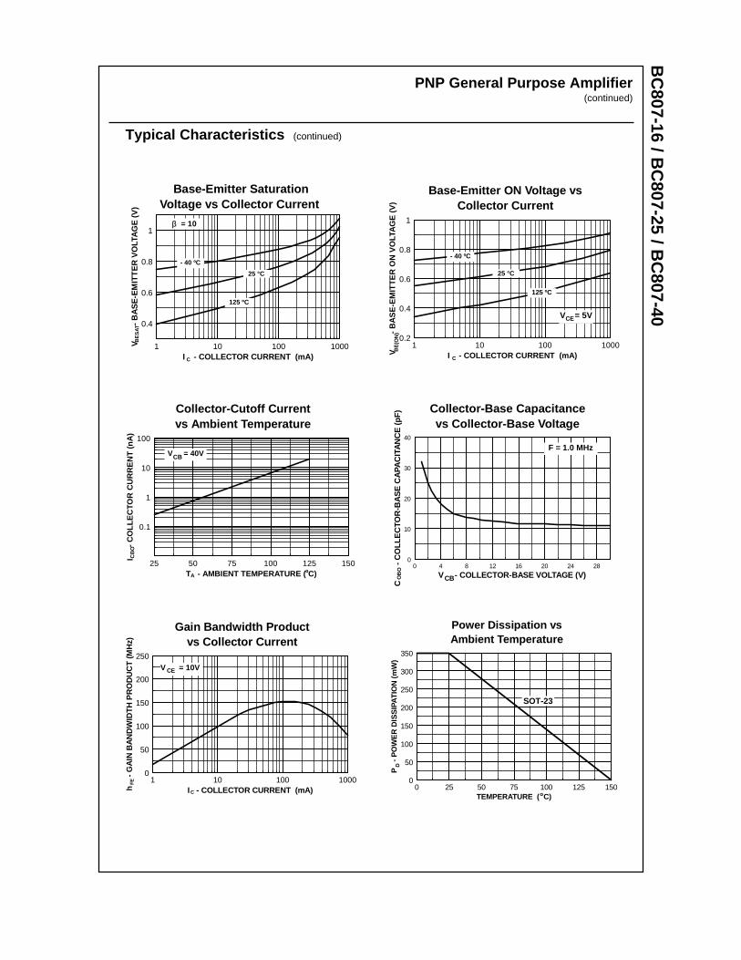
Power Dissipation vsAmbient Temperature
0 25 50 75 100 125 1500
50
100
150
200
250
300
350
TEMPERATURE ( C)
P
- P
OW
ER
DIS
SIP
ATIO
N (
mW
)D
o
SOT-23
Typical Characteristics (continued)
Base-Emitter ON Voltage vsCollector Current
1 10 100 10000.2
0.4
0.6
0.8
1
I - COLLECTOR CURRENT (mA)V
-
BA
SE
-EM
ITT
ER
ON
VO
LTA
GE
(V
)B
E(O
N)
125 ºC
- 40 ºC
25 °C
C
V = 5VCE
Collector-Cutoff Currentvs Ambient Temperature
25 50 75 100 125 150
0.1
1
10
100
T - AMBIENT TEMPERATURE ( C)
I
- C
OLL
EC
TOR
CU
RR
EN
T (
nA)
A
V = 40VCB
º
CB
O
Base-Emitter SaturationVoltage vs Collector Current
1 10 100 1000
0.4
0.6
0.8
1
I - COLLECTOR CURRENT (mA)
V
-
BA
SE
-EM
ITT
ER
VO
LTA
GE
(V)
BE
SAT
C
β = 10
125 ºC
- 40 ºC
25 °C
Collector-Base Capacitancevs Collector-Base Voltage
Pr 78
0 4 8 12 16 20 24 280
10
20
30
40
V - COLLECTOR-BASE VOLTAGE (V)
C
-
CO
LLE
CTO
R-B
AS
E C
APA
CIT
AN
CE
(pF
)
CBOB
O
F = 1.0 MHz
Gain Bandwidth Productvs Collector Current
1 10 100 10000
50
100
150
200
250
I - COLLECTOR CURRENT (mA)h
- G
AIN
BA
ND
WID
TH
PR
OD
UC
T (M
Hz)
C
FE
V = 10VCE

TRADEMARKS
ACEx™CoolFET™CROSSVOLT™E2CMOSTM
FACT™FACT Quiet Series™FAST®
FASTr™GTO™HiSeC™
The following are registered and unregistered trademarks Fairchild Semiconductor owns or is authorized to use and isnot intended to be an exhaustive list of all such trademarks.
LIFE SUPPORT POLICY
FAIRCHILD’S PRODUCTS ARE NOT AUTHORIZED FOR USE AS CRITICAL COMPONENTS IN LIFE SUPPORTDEVICES OR SYSTEMS WITHOUT THE EXPRESS WRITTEN APPROVAL OF FAIRCHILD SEMICONDUCTOR CORPORATION.As used herein:
ISOPLANAR™MICROWIRE™POP™PowerTrench™QS™Quiet Series™SuperSOT™-3SuperSOT™-6SuperSOT™-8TinyLogic™
1. Life support devices or systems are devices orsystems which, (a) are intended for surgical implant intothe body, or (b) support or sustain life, or (c) whosefailure to perform when properly used in accordancewith instructions for use provided in the labeling, can bereasonably expected to result in significant injury to theuser.
2. A critical component is any component of a lifesupport device or system whose failure to perform canbe reasonably expected to cause the failure of the lifesupport device or system, or to affect its safety oreffectiveness.
PRODUCT STATUS DEFINITIONS
Definition of Terms
Datasheet Identification Product Status Definition
Advance Information
Preliminary
No Identification Needed
Obsolete
This datasheet contains the design specifications forproduct development. Specifications may change inany manner without notice.
This datasheet contains preliminary data, andsupplementary data will be published at a later date.Fairchild Semiconductor reserves the right to makechanges at any time without notice in order to improvedesign.
This datasheet contains final specifications. FairchildSemiconductor reserves the right to make changes atany time without notice in order to improve design.
This datasheet contains specifications on a productthat has been discontinued by Fairchild semiconductor.The datasheet is printed for reference information only.
Formative orIn Design
First Production
Full Production
Not In Production
DISCLAIMER
FAIRCHILD SEMICONDUCTOR RESERVES THE RIGHT TO MAKE CHANGES WITHOUT FURTHERNOTICE TO ANY PRODUCTS HEREIN TO IMPROVE RELIABILITY, FUNCTION OR DESIGN. FAIRCHILDDOES NOT ASSUME ANY LIABILITY ARISING OUT OF THE APPLICATION OR USE OF ANY PRODUCTOR CIRCUIT DESCRIBED HEREIN; NEITHER DOES IT CONVEY ANY LICENSE UNDER ITS PATENTRIGHTS, NOR THE RIGHTS OF OTHERS.

BC807/BC808 PNP EPITAXIAL SILICON TRANSISTOR
SWITCHING AND AMPLIFIER APPLICATIONS• Suitable for AF-Driver stages and low power output stages• Complement to BC817/BC818
ABSOLUTE MAXIMUM RATINGS (TA=25°°C)
ELECTRICAL CHARACTERISTICS (TA=25°°C)
hFE CLASSIFICATION
MARKING CODE
Characteristic Symbol Rating Unit
Collector Emitter Voltage : BC807 : BC808Collector Emitter Voltage : BC807
: BC808Emitter-Base VoltageCollector Current (DC)Collector DissipationJunction TemperatureStorage Temperature
VCES
VCEO
VEBO
ICPC
TJ
TSTG
-50-30-45-25-5
-800-310150
-65 ~ 150
VVVVV
mAmW°C°C
Characteristic Symbol Test Conditions Min Typ Max Unit
Collector-Emitter Breakdown Voltage: BC807: BC808
Collector-Emitter Breakdown Voltage: BC807: BC808
Emitter-Base Breakdown VoltageCollector Cut-off CurrentEmitter Cut-off CurrentDC Current Gain
Collector-Emitter Saturation VoltageBase-Emitter On VoltageCurrent Gain Bandwidth Product
Collector-Base Capacitance
BVCEO
BVCES
BVEBO
ICES
IEBO
hFE1hFE2VCE (sat)VBE (on)fT
CCBO
IC= -10mA, IB=0
IC= -0.1mA, IB=0
IE= -0.1mA, IC=0VCE= -25V, IB=0VEB= -4V, IC=0VCE= -1V, IC= -100mAVCE= -1V, IC= -300mAIC= -500mA, IB= -50mAVCE= -1V, IC= -300mAVCE= -5V, IC= -10mAf=50MHzVCB= -10V, f=1MHz
-45-25
-50-30-5
10060
100
-100-100630
-0.7-1.2
12
VV
VVVnAnA
VV
MHz
pF
Classification 16 25 40
hFE1 100-250 160-400 250-630
hFE2 60- 100- 170-
TYPE 807-16 807-25 807-40 808-16 808-25 808-40
MARKING 9FA 9FB 9FC 9GA 9GB 9GC
SOT-23
1. Base 2. Emitter 3. Collector
1999 Fairchild Semiconductor Corporation
Rev. B
BC807/BC808 PNP EPITAXIAL SILICON TRANSISTOR
BC807/BC808 PNP EPITAXIAL SILICON TRANSISTOR

TRADEMARKS
ACEx™CoolFET™CROSSVOLT™E2CMOSTM
FACT™FACT Quiet Series™FAST®
FASTr™GTO™HiSeC™
The following are registered and unregistered trademarks Fairchild Semiconductor owns or is authorized to use and isnot intended to be an exhaustive list of all such trademarks.
LIFE SUPPORT POLICY
FAIRCHILD’S PRODUCTS ARE NOT AUTHORIZED FOR USE AS CRITICAL COMPONENTS IN LIFE SUPPORTDEVICES OR SYSTEMS WITHOUT THE EXPRESS WRITTEN APPROVAL OF FAIRCHILD SEMICONDUCTOR CORPORATION.As used herein:
ISOPLANAR™MICROWIRE™POP™PowerTrench™QS™Quiet Series™SuperSOT™-3SuperSOT™-6SuperSOT™-8TinyLogic™
1. Life support devices or systems are devices orsystems which, (a) are intended for surgical implant intothe body, or (b) support or sustain life, or (c) whosefailure to perform when properly used in accordancewith instructions for use provided in the labeling, can bereasonably expected to result in significant injury to theuser.
2. A critical component is any component of a lifesupport device or system whose failure to perform canbe reasonably expected to cause the failure of the lifesupport device or system, or to affect its safety oreffectiveness.
PRODUCT STATUS DEFINITIONS
Definition of Terms
Datasheet Identification Product Status Definition
Advance Information
Preliminary
No Identification Needed
Obsolete
This datasheet contains the design specifications forproduct development. Specifications may change inany manner without notice.
This datasheet contains preliminary data, andsupplementary data will be published at a later date.Fairchild Semiconductor reserves the right to makechanges at any time without notice in order to improvedesign.
This datasheet contains final specifications. FairchildSemiconductor reserves the right to make changes atany time without notice in order to improve design.
This datasheet contains specifications on a productthat has been discontinued by Fairchild semiconductor.The datasheet is printed for reference information only.
Formative orIn Design
First Production
Full Production
Not In Production
DISCLAIMER
FAIRCHILD SEMICONDUCTOR RESERVES THE RIGHT TO MAKE CHANGES WITHOUT FURTHERNOTICE TO ANY PRODUCTS HEREIN TO IMPROVE RELIABILITY, FUNCTION OR DESIGN. FAIRCHILDDOES NOT ASSUME ANY LIABILITY ARISING OUT OF THE APPLICATION OR USE OF ANY PRODUCTOR CIRCUIT DESCRIBED HEREIN; NEITHER DOES IT CONVEY ANY LICENSE UNDER ITS PATENTRIGHTS, NOR THE RIGHTS OF OTHERS.
BC
817-25 / BC
817-40
BC817-25BC817-40
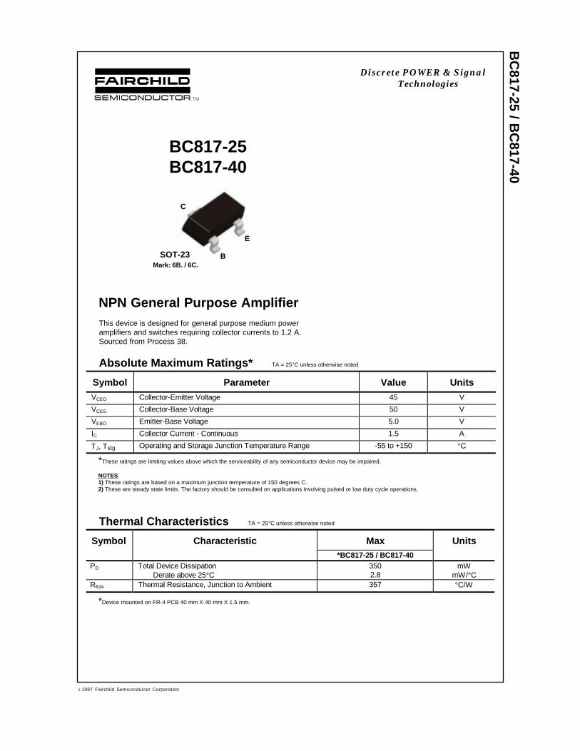
NPN General Purpose AmplifierThis device is designed for general purpose medium poweramplifiers and switches requiring collector currents to 1.2 A.Sourced from Process 38.
Absolute Maximum Ratings* TA = 25°C unless otherwise noted
*These ratings are limiting values above which the serviceability of any semiconductor device may be impaired.
NOTES:1) These ratings are based on a maximum junction temperature of 150 degrees C.2) These are steady state limits. The factory should be consulted on applications involving pulsed or low duty cycle operations.
Thermal Characteristics TA = 25°C unless otherwise noted
Symbol Characteristic Max Units*BC817-25 / BC817-40
PD Total Device DissipationDerate above 25°C
3502.8
mWmW/°C
RθJA Thermal Resistance, Junction to Ambient 357 °C/W
Symbol Parameter Value UnitsVCEO Collector-Emitter Voltage 45 V
VCES Collector-Base Voltage 50 V
VEBO Emitter-Base Voltage 5.0 V
IC Collector Current - Continuous 1.5 A
TJ, Tstg Operating and Storage Junction Temperature Range -55 to +150 °C
SOT-23
C
E
BMark: 6B. / 6C.
*Device mounted on FR-4 PCB 40 mm X 40 mm X 1.5 mm.
Discrete POWER & SignalTechnologies
ã 1997 Fairchild Semiconductor Corporation
BC
817-25 / BC
817-40
Electrical Characteristics TA = 25°C unless otherwise noted
OFF CHARACTERISTICS
Symbol Parameter Test C onditions Min Max Units
V(BR)CEO Collector-Emitter Breakdown Voltage IC = 10 mA, IB = 0 45 V
V(BR)CES Collector-Base Breakdown Voltage IC = 100 µA, IE = 0 50 V
V(BR)EBO Emitter-Base Breakdown Voltage IE = 10 µA, IC = 0 5.0 V
ICBO Collector-Cutoff Current VCB = 20 VVCB = 20 V, TA = 150°C
1005.0
nAµA
ON CHARACTERISTICShFE DC Current Gain IC = 100 mA, VCE = 1.0 V - 25
- 40IC = 500 mA, VCE = 1.0 V
16025040
400600
VCE(sat) Collector-Emitter Saturation Voltage IC = 500 mA, IB = 50 mA 0.7 V
VBE(on) Base-Emitter On Voltage IC = 500 mA, VCE = 1.0 V 1.2 V
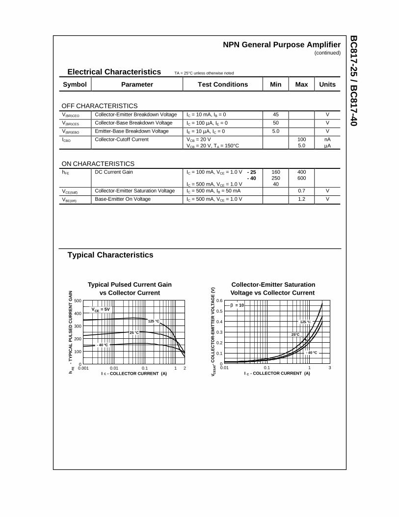
NPN General Purpose Amplifier(continued)
Typical Characteristics
Collector-Emitter SaturationVoltage vs Collector Current
0.01 0.1 1 30
0.1
0.2
0.3
0.4
0.5
0.6
I - COLLECTOR CURRENT (A)V
-
CO
LLE
CTO
R-E
MIT
TE
R V
OLT
AG
E (
V)
CE
SAT
C
β = 10
125 ºC
- 40 ºC
25°C
Typical Pulsed Current Gainvs Collector Current
0.001 0.01 0.1 1 20
100
200
300
400
500
I - COLLECTOR CURRENT (A)h
- T
YP
ICA
L P
ULS
ED
CU
RR
EN
T G
AIN
FE
- 40 ºC
25 °C
C
V = 5VCE
125 °C
BC
817-25 / BC
817-40NPN General Purpose Amplifier
(continued)
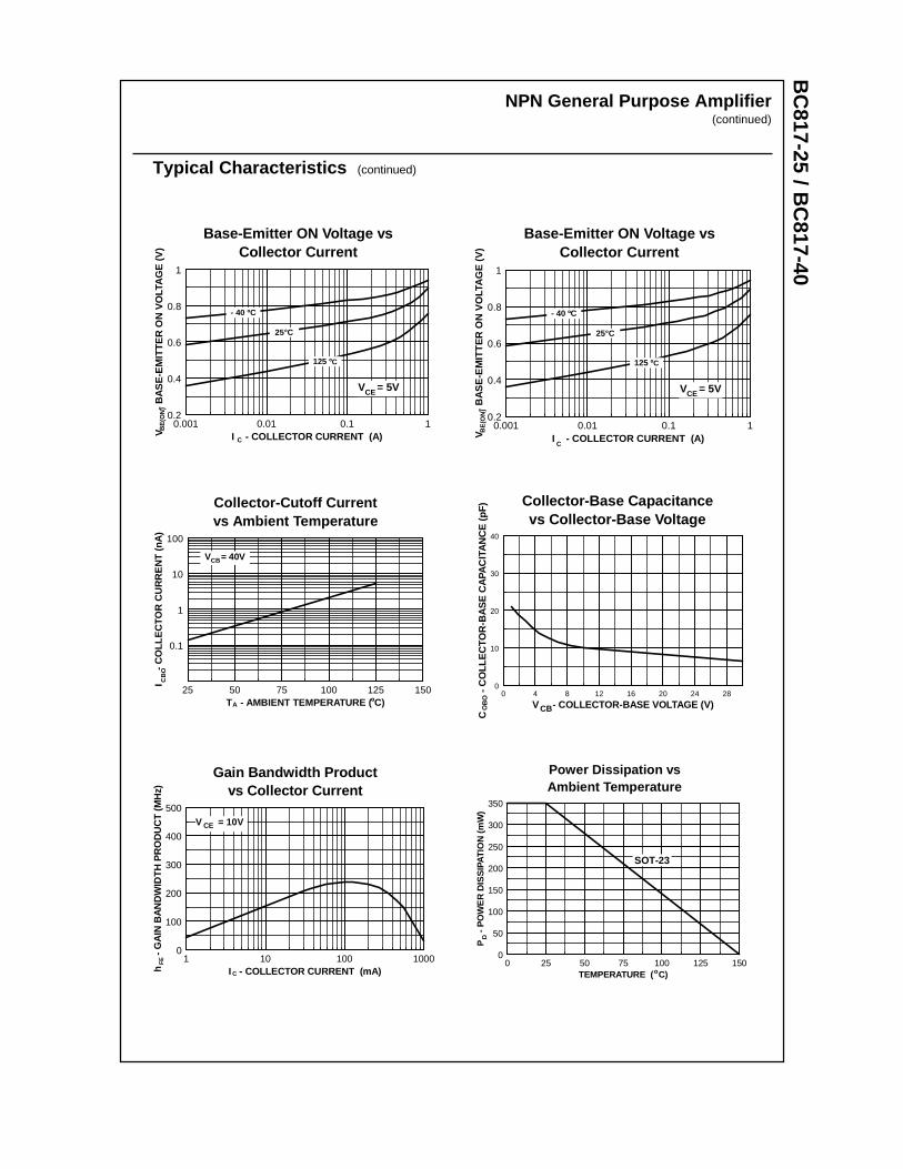
Typical Characteristics (continued)
Base-Emitter ON Voltage vsCollector Current
P 38
0.001 0.01 0.1 10.2
0.4
0.6
0.8
1
I - COLLECTOR CURRENT (A)V
-
BA
SE
-EM
ITT
ER
ON
VO
LTA
GE
(V
)B
E(O
N)
C
V = 5VCE
125 ºC
- 40 ºC
25°C
Base-Emitter ON Voltage vsCollector Current
P
0.001 0.01 0.1 10.2
0.4
0.6
0.8
1
I - COLLECTOR CURRENT (A)V
-
BA
SE
-EM
ITT
ER
ON
VO
LTA
GE
(V)
BE
(ON
)
C
V = 5VCE
125 ºC
- 40 ºC
25°C
Collector-Cutoff Currentvs Ambient Temperature
25 50 75 100 125 150
0.1
1
10
100
T - AMBIENT TEMPERATURE ( C)
I
- C
OLL
EC
TOR
CU
RR
EN
T (
nA)
A
V = 40VCB
º
CB
O
Collector-Base Capacitancevs Collector-Base Voltage
Pr 38
0 4 8 12 16 20 24 280
10
20
30
40
V - COLLECTOR-BASE VOLTAGE (V)
C
-
CO
LLE
CTO
R-B
AS
E C
APA
CIT
AN
CE
(pF
)
CBOB
O
Gain Bandwidth Productvs Collector Current
1 10 100 10000
100
200
300
400
500
I - COLLECTOR CURRENT (mA)h
- G
AIN
BA
ND
WID
TH
PR
OD
UC
T (
MH
z)
C
FE
V = 10VCE
Power Dissipation vsAmbient Temperature
0 25 50 75 100 125 1500
50
100
150
200
250
300
350
TEMPERATURE ( C)
P
- P
OW
ER
DIS
SIP
ATIO
N (
mW
)D
o
SOT-23

TRADEMARKS
ACEx™CoolFET™CROSSVOLT™E2CMOSTM
FACT™FACT Quiet Series™FAST®
FASTr™GTO™HiSeC™
The following are registered and unregistered trademarks Fairchild Semiconductor owns or is authorized to use and isnot intended to be an exhaustive list of all such trademarks.
LIFE SUPPORT POLICY
FAIRCHILD’S PRODUCTS ARE NOT AUTHORIZED FOR USE AS CRITICAL COMPONENTS IN LIFE SUPPORTDEVICES OR SYSTEMS WITHOUT THE EXPRESS WRITTEN APPROVAL OF FAIRCHILD SEMICONDUCTOR CORPORATION.As used herein:
ISOPLANAR™MICROWIRE™POP™PowerTrench™QS™Quiet Series™SuperSOT™-3SuperSOT™-6SuperSOT™-8TinyLogic™
1. Life support devices or systems are devices orsystems which, (a) are intended for surgical implant intothe body, or (b) support or sustain life, or (c) whosefailure to perform when properly used in accordancewith instructions for use provided in the labeling, can bereasonably expected to result in significant injury to theuser.
2. A critical component is any component of a lifesupport device or system whose failure to perform canbe reasonably expected to cause the failure of the lifesupport device or system, or to affect its safety oreffectiveness.
PRODUCT STATUS DEFINITIONS
Definition of Terms
Datasheet Identification Product Status Definition
Advance Information
Preliminary
No Identification Needed
Obsolete
This datasheet contains the design specifications forproduct development. Specifications may change inany manner without notice.
This datasheet contains preliminary data, andsupplementary data will be published at a later date.Fairchild Semiconductor reserves the right to makechanges at any time without notice in order to improvedesign.
This datasheet contains final specifications. FairchildSemiconductor reserves the right to make changes atany time without notice in order to improve design.
This datasheet contains specifications on a productthat has been discontinued by Fairchild semiconductor.The datasheet is printed for reference information only.
Formative orIn Design
First Production
Full Production
Not In Production
DISCLAIMER
FAIRCHILD SEMICONDUCTOR RESERVES THE RIGHT TO MAKE CHANGES WITHOUT FURTHERNOTICE TO ANY PRODUCTS HEREIN TO IMPROVE RELIABILITY, FUNCTION OR DESIGN. FAIRCHILDDOES NOT ASSUME ANY LIABILITY ARISING OUT OF THE APPLICATION OR USE OF ANY PRODUCTOR CIRCUIT DESCRIBED HEREIN; NEITHER DOES IT CONVEY ANY LICENSE UNDER ITS PATENTRIGHTS, NOR THE RIGHTS OF OTHERS.
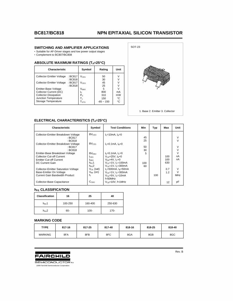
BC817/BC818 NPN EPITAXIAL SILICON TRANSISTOR
SWITCHING AND AMPLIFIER APPLICATIONS• Suitable for AF-Driver stages and low power output stages• Complement to BC807/BC808
ABSOLUTE MAXIMUM RATINGS (TA=25°°C)
ELECTRICAL CHARACTERISTICS (TA=25°°C)
hFE CLASSIFICATION
MARKING CODE
Characteristic Symbol Rating Unit
Collector Emitter Voltage : BC817 : BC818
Collector Emitter Voltage : BC817 : BC818
Emitter-Base VoltageCollector Current (DC)Collector DissipationJunction TemperatureStorage Temperature
VCES
VCEO
VEBO
ICPC
TJ
TSTG
503045255
800310150
-65 ~ 150
VVVVV
mAmW°C°C
Characteristic Symbol Test Conditions Min Typ Max Unit
Collector-Emitter Breakdown Voltage: BC817: BC818
Collector-Emitter Breakdown Voltage: BC817: BC818
Emitter-Base Breakdown VoltageCollector Cut-off CurrentEmitter Cut-off CurrentDC Current Gain
Collector-Emitter Saturation VoltageBase-Emitter On VoltageCurrent Gain Bandwidth Product
Collector-Base Capacitance
BVCEO
BVCES
BVEBO
ICES
IEBO
hFE1hFE2VCE (sat)VBE (on)fT
CCBO
IC=10mA, IB=0
IC=0.1mA, IB=0
IE=0.1mA, IC=0VCE=25V, IB=0VEB=4V, IC=0VCE=1V, IC=100mAVCE=1V, IC=300mAIC=500mA, IB=50mAVCE=1V, IC=300mAVCE=5V, IC=10mAf=50MHzVCB=10V, f=1MHz
4525
50305
10060
100
100100630
0.71.2
12
VV
VVVnAnA
VV
MHz
pF
Classification 16 25 40
hFE1 100-250 160-400 250-630
hFE2 60- 100- 170-
TYPE 817-16 817-25 817-40 818-16 818-25 818-40
MARKING 8FA 8FB 8FC 8GA 8GB 8GC
SOT-23
1. Base 2. Emitter 3. Collector
1999 Fairchild Semiconductor Corporation
Rev. B

TRADEMARKS
ACEx™CoolFET™CROSSVOLT™E2CMOSTM
FACT™FACT Quiet Series™FAST®
FASTr™GTO™HiSeC™
The following are registered and unregistered trademarks Fairchild Semiconductor owns or is authorized to use and isnot intended to be an exhaustive list of all such trademarks.
LIFE SUPPORT POLICY
FAIRCHILD’S PRODUCTS ARE NOT AUTHORIZED FOR USE AS CRITICAL COMPONENTS IN LIFE SUPPORTDEVICES OR SYSTEMS WITHOUT THE EXPRESS WRITTEN APPROVAL OF FAIRCHILD SEMICONDUCTOR CORPORATION.As used herein:
ISOPLANAR™MICROWIRE™POP™PowerTrench™QS™Quiet Series™SuperSOT™-3SuperSOT™-6SuperSOT™-8TinyLogic™
1. Life support devices or systems are devices orsystems which, (a) are intended for surgical implant intothe body, or (b) support or sustain life, or (c) whosefailure to perform when properly used in accordancewith instructions for use provided in the labeling, can bereasonably expected to result in significant injury to theuser.
2. A critical component is any component of a lifesupport device or system whose failure to perform canbe reasonably expected to cause the failure of the lifesupport device or system, or to affect its safety oreffectiveness.
PRODUCT STATUS DEFINITIONS
Definition of Terms
Datasheet Identification Product Status Definition
Advance Information
Preliminary
No Identification Needed
Obsolete
This datasheet contains the design specifications forproduct development. Specifications may change inany manner without notice.
This datasheet contains preliminary data, andsupplementary data will be published at a later date.Fairchild Semiconductor reserves the right to makechanges at any time without notice in order to improvedesign.
This datasheet contains final specifications. FairchildSemiconductor reserves the right to make changes atany time without notice in order to improve design.
This datasheet contains specifications on a productthat has been discontinued by Fairchild semiconductor.The datasheet is printed for reference information only.
Formative orIn Design
First Production
Full Production
Not In Production
DISCLAIMER
FAIRCHILD SEMICONDUCTOR RESERVES THE RIGHT TO MAKE CHANGES WITHOUT FURTHERNOTICE TO ANY PRODUCTS HEREIN TO IMPROVE RELIABILITY, FUNCTION OR DESIGN. FAIRCHILDDOES NOT ASSUME ANY LIABILITY ARISING OUT OF THE APPLICATION OR USE OF ANY PRODUCTOR CIRCUIT DESCRIBED HEREIN; NEITHER DOES IT CONVEY ANY LICENSE UNDER ITS PATENTRIGHTS, NOR THE RIGHTS OF OTHERS.
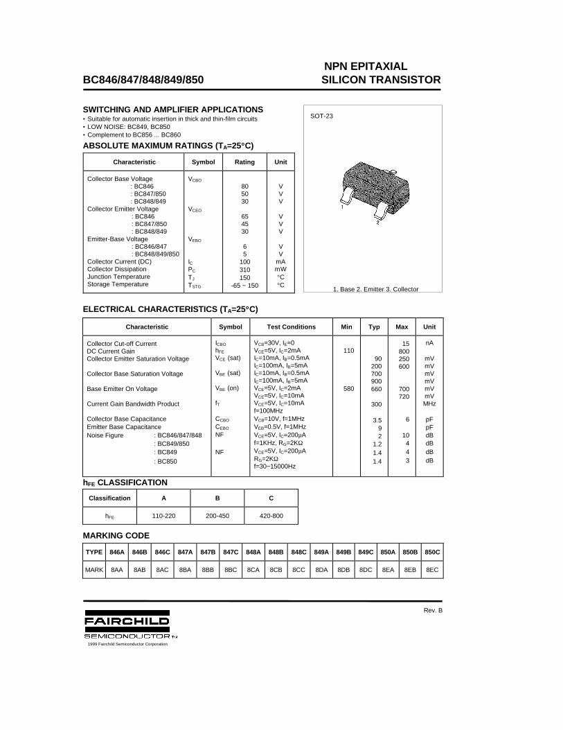
NPN EPITAXIALBC846/847/848/849/850 SILICON TRANSISTOR
SWITCHING AND AMPLIFIER APPLICATIONS• Suitable for automatic insertion in thick and thin-film circuits• LOW NOISE: BC849, BC850• Complement to BC856 ... BC860
ABSOLUTE MAXIMUM RATINGS (TA=25°°C)
ELECTRICAL CHARACTERISTICS (TA=25°°C)
hFE CLASSIFICATION
MARKING CODE
Characteristic Symbol Rating Unit
Collector Base Voltage : BC846 : BC847/850 : BC848/849Collector Emitter Voltage : BC846 : BC847/850 : BC848/849Emitter-Base Voltage : BC846/847 : BC848/849/850Collector Current (DC)Collector DissipationJunction TemperatureStorage Temperature
VCBO
VCEO
VEBO
ICPC
TJ
TSTG
805030
654530
65
100310150
-65 ~ 150
VVV
VVV
VV
mAmW°C°C
Characteristic Symbol Test Conditions Min Typ Max Unit
Collector Cut-off CurrentDC Current GainCollector Emitter Saturation Voltage
Collector Base Saturation Voltage
Base Emitter On Voltage
Current Gain Bandwidth Product
Collector Base CapacitanceEmitter Base CapacitanceNoise Figure : BC846/847/848 : BC849/850 : BC849
: BC850
ICBO
hFE
VCE (sat)
VBE (sat)
VBE (on)
fT
CCBO
CEBO
NF
NF
VCB=30V, IE=0VCE=5V, IC=2mAIC=10mA, IB=0.5mAIC=100mA, IB=5mAIC=10mA, IB=0.5mAIC=100mA, IB=5mAVCE=5V, IC=2mAVCE=5V, IC=10mAVCE=5V, IC=10mAf=100MHzVCB=10V, f=1MHzVEB=0.5V, f=1MHzVCE=5V, IC=200µAf=1KHz, RG=2KΩVCE=5V, IC=200µARG=2KΩf=30~15000Hz
110
580
90200700900660
300
3.592
1.21.41.4
15800250600
700720
6
10443
nA
mVmVmVmVmVmVMHz
pFpFdBdBdBdB
Classification A B C
hFE 110-220 200-450 420-800
TYPE 846A 846B 846C 847A 847B 847C 848A 848B 848C 849A 849B 849C 850A 850B 850C
MARK 8AA 8AB 8AC 8BA 8BB 8BC 8CA 8CB 8CC 8DA 8DB 8DC 8EA 8EB 8EC
SOT-23
1. Base 2. Emitter 3. Collector
1999 Fairchild Semiconductor Corporation
Rev. B
NPN EPITAXIALBC846/847/848/849/850 SILICON TRANSISTOR

TRADEMARKS
ACEx™CoolFET™CROSSVOLT™E2CMOSTM
FACT™FACT Quiet Series™FAST®
FASTr™GTO™HiSeC™
The following are registered and unregistered trademarks Fairchild Semiconductor owns or is authorized to use and isnot intended to be an exhaustive list of all such trademarks.
LIFE SUPPORT POLICY
FAIRCHILD’S PRODUCTS ARE NOT AUTHORIZED FOR USE AS CRITICAL COMPONENTS IN LIFE SUPPORTDEVICES OR SYSTEMS WITHOUT THE EXPRESS WRITTEN APPROVAL OF FAIRCHILD SEMICONDUCTOR CORPORATION.As used herein:
ISOPLANAR™MICROWIRE™POP™PowerTrench™QS™Quiet Series™SuperSOT™-3SuperSOT™-6SuperSOT™-8TinyLogic™
1. Life support devices or systems are devices orsystems which, (a) are intended for surgical implant intothe body, or (b) support or sustain life, or (c) whosefailure to perform when properly used in accordancewith instructions for use provided in the labeling, can bereasonably expected to result in significant injury to theuser.
2. A critical component is any component of a lifesupport device or system whose failure to perform canbe reasonably expected to cause the failure of the lifesupport device or system, or to affect its safety oreffectiveness.
PRODUCT STATUS DEFINITIONS
Definition of Terms
Datasheet Identification Product Status Definition
Advance Information
Preliminary
No Identification Needed
Obsolete
This datasheet contains the design specifications forproduct development. Specifications may change inany manner without notice.
This datasheet contains preliminary data, andsupplementary data will be published at a later date.Fairchild Semiconductor reserves the right to makechanges at any time without notice in order to improvedesign.
This datasheet contains final specifications. FairchildSemiconductor reserves the right to make changes atany time without notice in order to improve design.
This datasheet contains specifications on a productthat has been discontinued by Fairchild semiconductor.The datasheet is printed for reference information only.
Formative orIn Design
First Production
Full Production
Not In Production
DISCLAIMER
FAIRCHILD SEMICONDUCTOR RESERVES THE RIGHT TO MAKE CHANGES WITHOUT FURTHERNOTICE TO ANY PRODUCTS HEREIN TO IMPROVE RELIABILITY, FUNCTION OR DESIGN. FAIRCHILDDOES NOT ASSUME ANY LIABILITY ARISING OUT OF THE APPLICATION OR USE OF ANY PRODUCTOR CIRCUIT DESCRIBED HEREIN; NEITHER DOES IT CONVEY ANY LICENSE UNDER ITS PATENTRIGHTS, NOR THE RIGHTS OF OTHERS.
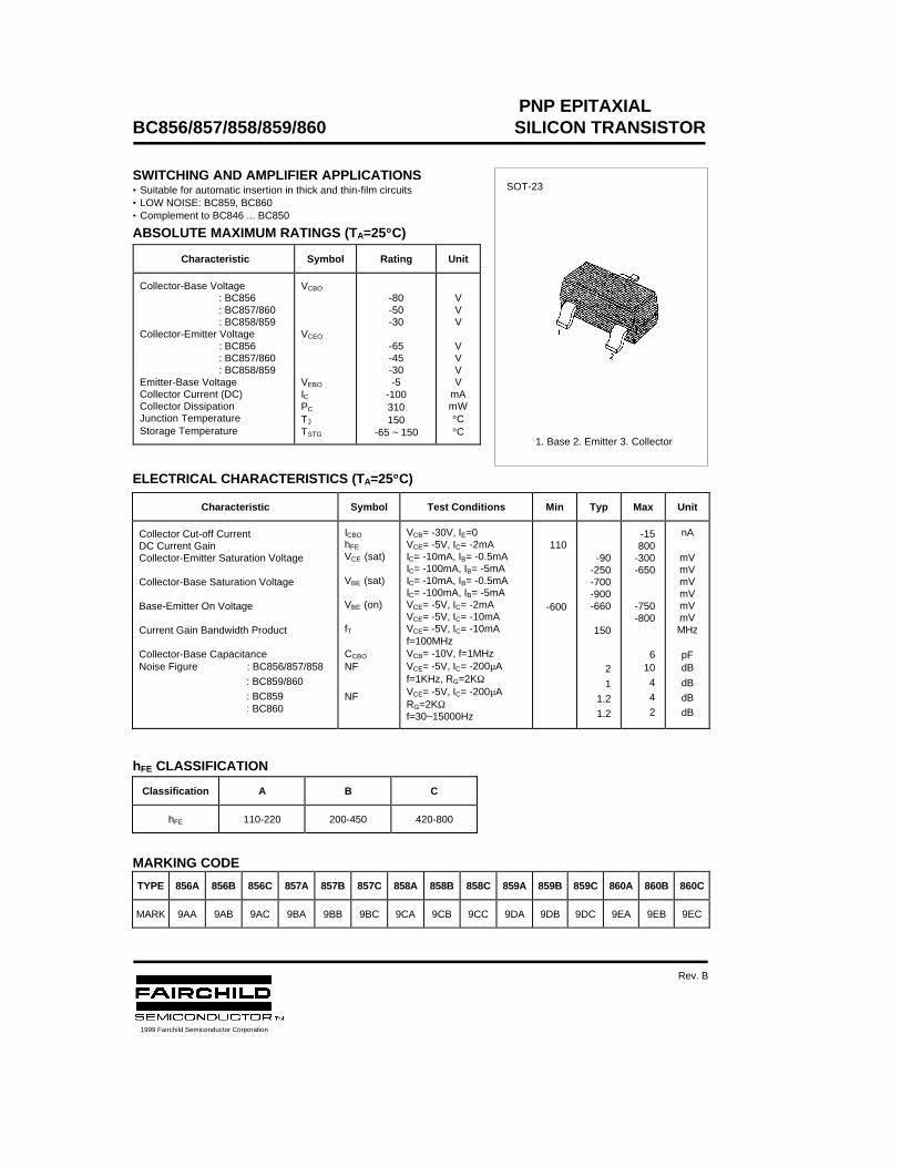
PNP EPITAXIALBC856/857/858/859/860 SILICON TRANSISTOR
SWITCHING AND AMPLIFIER APPLICATIONS• Suitable for automatic insertion in thick and thin-film circuits• LOW NOISE: BC859, BC860• Complement to BC846 ... BC850
ABSOLUTE MAXIMUM RATINGS (TA=25°°C)
ELECTRICAL CHARACTERISTICS (TA=25°°C)
hFE CLASSIFICATION
MARKING CODE
Characteristic Symbol Rating Unit
Collector-Base Voltage: BC856: BC857/860: BC858/859
Collector-Emitter Voltage: BC856: BC857/860: BC858/859
Emitter-Base VoltageCollector Current (DC)Collector DissipationJunction TemperatureStorage Temperature
VCBO
VCEO
VEBO
ICPC
TJ
TSTG
-80-50-30
-65-45-30-5
-100310150
-65 ~ 150
VVV
VVVV
mAmW°C°C
Characteristic Symbol Test Conditions Min Typ Max Unit
Collector Cut-off CurrentDC Current GainCollector-Emitter Saturation Voltage
Collector-Base Saturation Voltage
Base-Emitter On Voltage
Current Gain Bandwidth Product
Collector-Base CapacitanceNoise Figure : BC856/857/858
: BC859/860
: BC859 : BC860
ICBO
hFE
VCE (sat)
VBE (sat)
VBE (on)
fT
CCBO
NF
NF
VCB= -30V, IE=0VCE= -5V, IC= -2mAIC= -10mA, IB= -0.5mAIC= -100mA, IB= -5mAIC= -10mA, IB= -0.5mAIC= -100mA, IB= -5mAVCE= -5V, IC= -2mAVCE= -5V, IC= -10mAVCE= -5V, IC= -10mAf=100MHzVCB= -10V, f=1MHzVCE= -5V, IC= -200µAf=1KHz, RG=2KΩVCE= -5V, IC= -200µARG=2KΩf=30~15000Hz
110
-600
-90-250-700-900-660
150
2
1
1.2
1.2
-15800
-300-650
-750-800
610
4
4
2
nA
mVmVmVmVmVmVMHz
pFdB
dB
dB
dB
Classification A B C
hFE 110-220 200-450 420-800
TYPE 856A 856B 856C 857A 857B 857C 858A 858B 858C 859A 859B 859C 860A 860B 860C
MARK 9AA 9AB 9AC 9BA 9BB 9BC 9CA 9CB 9CC 9DA 9DB 9DC 9EA 9EB 9EC
SOT-23
1. Base 2. Emitter 3. Collector
1999 Fairchild Semiconductor Corporation
Rev. B
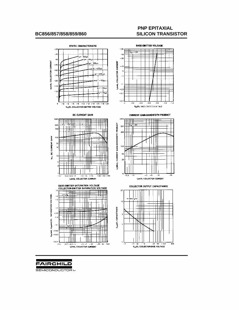
PNP EPITAXIALBC856/857/858/859/860 SILICON TRANSISTOR

TRADEMARKS
ACEx™CoolFET™CROSSVOLT™E2CMOSTM
FACT™FACT Quiet Series™FAST®
FASTr™GTO™HiSeC™
The following are registered and unregistered trademarks Fairchild Semiconductor owns or is authorized to use and isnot intended to be an exhaustive list of all such trademarks.
LIFE SUPPORT POLICY
FAIRCHILD’S PRODUCTS ARE NOT AUTHORIZED FOR USE AS CRITICAL COMPONENTS IN LIFE SUPPORTDEVICES OR SYSTEMS WITHOUT THE EXPRESS WRITTEN APPROVAL OF FAIRCHILD SEMICONDUCTOR CORPORATION.As used herein:
ISOPLANAR™MICROWIRE™POP™PowerTrench™QS™Quiet Series™SuperSOT™-3SuperSOT™-6SuperSOT™-8TinyLogic™
1. Life support devices or systems are devices orsystems which, (a) are intended for surgical implant intothe body, or (b) support or sustain life, or (c) whosefailure to perform when properly used in accordancewith instructions for use provided in the labeling, can bereasonably expected to result in significant injury to theuser.
2. A critical component is any component of a lifesupport device or system whose failure to perform canbe reasonably expected to cause the failure of the lifesupport device or system, or to affect its safety oreffectiveness.
PRODUCT STATUS DEFINITIONS
Definition of Terms
Datasheet Identification Product Status Definition
Advance Information
Preliminary
No Identification Needed
Obsolete
This datasheet contains the design specifications forproduct development. Specifications may change inany manner without notice.
This datasheet contains preliminary data, andsupplementary data will be published at a later date.Fairchild Semiconductor reserves the right to makechanges at any time without notice in order to improvedesign.
This datasheet contains final specifications. FairchildSemiconductor reserves the right to make changes atany time without notice in order to improve design.
This datasheet contains specifications on a productthat has been discontinued by Fairchild semiconductor.The datasheet is printed for reference information only.
Formative orIn Design
First Production
Full Production
Not In Production
DISCLAIMER
FAIRCHILD SEMICONDUCTOR RESERVES THE RIGHT TO MAKE CHANGES WITHOUT FURTHERNOTICE TO ANY PRODUCTS HEREIN TO IMPROVE RELIABILITY, FUNCTION OR DESIGN. FAIRCHILDDOES NOT ASSUME ANY LIABILITY ARISING OUT OF THE APPLICATION OR USE OF ANY PRODUCTOR CIRCUIT DESCRIBED HEREIN; NEITHER DOES IT CONVEY ANY LICENSE UNDER ITS PATENTRIGHTS, NOR THE RIGHTS OF OTHERS.
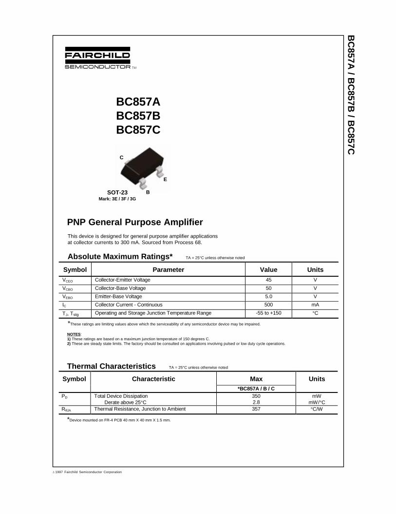
BC
857A / B
C857B
/ BC
857C
BC857ABC857BBC857C
PNP General Purpose AmplifierThis device is designed for general purpose amplifier applicationsat collector currents to 300 mA. Sourced from Process 68.
Absolute Maximum Ratings * TA = 25°C unless otherwise noted
*These ratings are limiting values above which the serviceability of any semiconductor device may be impaired.
NOTES:1) These ratings are based on a maximum junction temperature of 150 degrees C.2) These are steady state limits. The factory should be consulted on applications involving pulsed or low duty cycle operations.
Thermal Characteristic s TA = 25°C unless otherwise noted
Symbol Parameter Value UnitsVCEO Collector-Emitter Voltage 45 V
VCBO Collector-Base Voltage 50 V
VEBO Emitter-Base Voltage 5.0 V
IC Collector Current - Continuous 500 mA
TJ, Tstg Operating and Storage Junction Temperature Range -55 to +150 °C
Symbol Character ist ic Max Units*BC857A / B / C
PD Total Device DissipationDerate above 25°C
3502.8
mWmW/°C
RθJA Thermal Resistance, Junction to Ambient 357 °C/W
C
B
E
SOT-23Mark: 3E / 3F / 3G
*Device mounted on FR-4 PCB 40 mm X 40 mm X 1.5 mm.
ã 1997 Fairchild Semiconductor Corporation
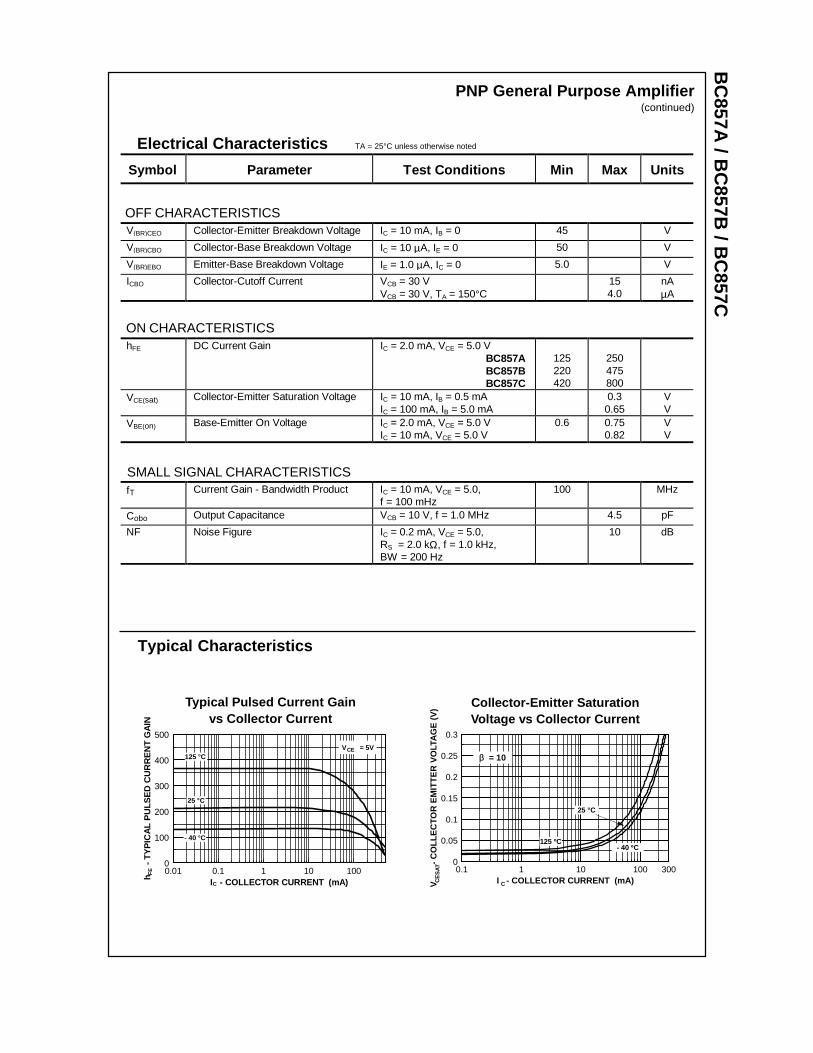
BC
857A / B
C857B
/ BC
857C
Electrical Characteristics TA = 25°C unless otherwise noted
OFF CHARACTERISTICS
Symbol Parameter Test C onditions Min Max Units
V(BR)CEO Collector-Emitter Breakdown Voltage IC = 10 mA, IB = 0 45 V
V(BR)CBO Collector-Base Breakdown Voltage IC = 10 µA, IE = 0 50 V
V(BR)EBO Emitter-Base Breakdown Voltage IE = 1.0 µA, IC = 0 5.0 V
ICBO Collector-Cutoff Current VCB = 30 VVCB = 30 V, TA = 150°C
154.0
nAµA
ON CHARACTERISTICShFE DC Current Gain IC = 2.0 mA, VCE = 5.0 V
BC857ABC857BBC857C
125220420
250475800
VCE(sat) Collector-Emitter Saturation Voltage IC = 10 mA, IB = 0.5 mAIC = 100 mA, IB = 5.0 mA
0.30.65
VV
VBE(on) Base-Emitter On Voltage IC = 2.0 mA, VCE = 5.0 VIC = 10 mA, VCE = 5.0 V
0.6 0.750.82
VV
SMALL SIGNAL CHARACTERISTICSfT Current Gain - Bandwidth Product IC = 10 mA, VCE = 5.0,
f = 100 mHz100 MHz
Cobo Output Capacitance VCB = 10 V, f = 1.0 MHz 4.5 pF
NF Noise Figure IC = 0.2 mA, VCE = 5.0,RS = 2.0 kΩ, f = 1.0 kHz,BW = 200 Hz
10 dB
PNP General Purpose Amplifier(continued)
Typical Characteristics
Collector-Emitter SaturationVoltage vs Collector Current
P 68
0.1 1 10 100 3000
0.05
0.1
0.15
0.2
0.25
0.3
I - COLLECTOR CURRENT (mA)V
-
CO
LLE
CTO
R E
MIT
TE
R V
OLT
AG
E (
V)
CCE
SAT
25 °C
- 40 ºC125 ºC
β = 10
Typical Pulsed Current Gainvs Collector Current
0.01 0.1 1 10 1000
100
200
300
400
500
I - COLLECTOR CURRENT (mA)h
- T
YP
ICA
L P
ULS
ED
CU
RR
EN
T G
AIN
C
FE
125 °C
25 °C
- 40 °C
V = 5VCE
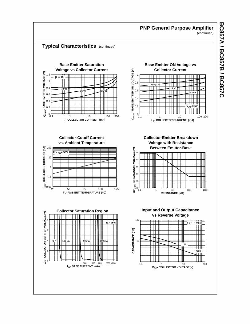
BC
857A / B
C857B
/ BC
857CPNP General Purpose Amplifier
(continued)
Typical Characteristics (continued)
Base-Emitter SaturationVoltage vs Collector Current
0.1 1 10 100 3000
0.2
0.4
0.6
0.8
1
1.2
I - COLLECTOR CURRENT (mA)
V
-
BA
SE
EM
ITT
ER
VO
LTA
GE
(V
)
C
BE
SAT
β = 10
25 °C- 40 ºC
125 ºC
Base Emitter ON Voltage vsCollector Current
0.1 1 10 100 2000
0.2
0.4
0.6
0.8
1
I - COLLECTOR CURRENT (mA)V
-
BA
SE
EM
ITT
ER
ON
VO
LTA
GE
(V
)
C
BE
ON
V = 5VCE
25 °C
- 40 ºC
125 ºC
Collector-Cutoff Currentvs. Ambient Temperature
25 50 75 100 1250.01
0.1
1
10
100
T - AMBIENT TEMPERATURE ( C)
I
- C
OLL
EC
TOR
CU
RR
EN
T (
nA)
A
CB
O
º
V = 50VCB
Ω
CE
R
Collector-Emitter BreakdownVoltage with ResistanceBetween Emitter-Base
0.1 1 10 100 100070
75
80
85
90
95
RESISTANCE (k )BV
- B
RE
AK
DO
WN
VO
LTA
GE
(V
)
Collector Saturation Region
100 300 700 2000 40000
1
2
3
4
I - BASE CURRENT (uA)
V
- C
OLL
EC
TOR
-EM
ITT
ER
VO
LTA
GE
(V
)C
E
B
50 mA 300 mA100 uA
Ta = 25°C
Ic =
Input and Output Capacitancevs Reverse Voltage
0.1 1 10 100
10
100
V - COLLECTOR VOLTAGE(V)
CA
PA
CIT
AN
CE
(pF
)
Cib
Cob
f = 1.0 MHz
ce
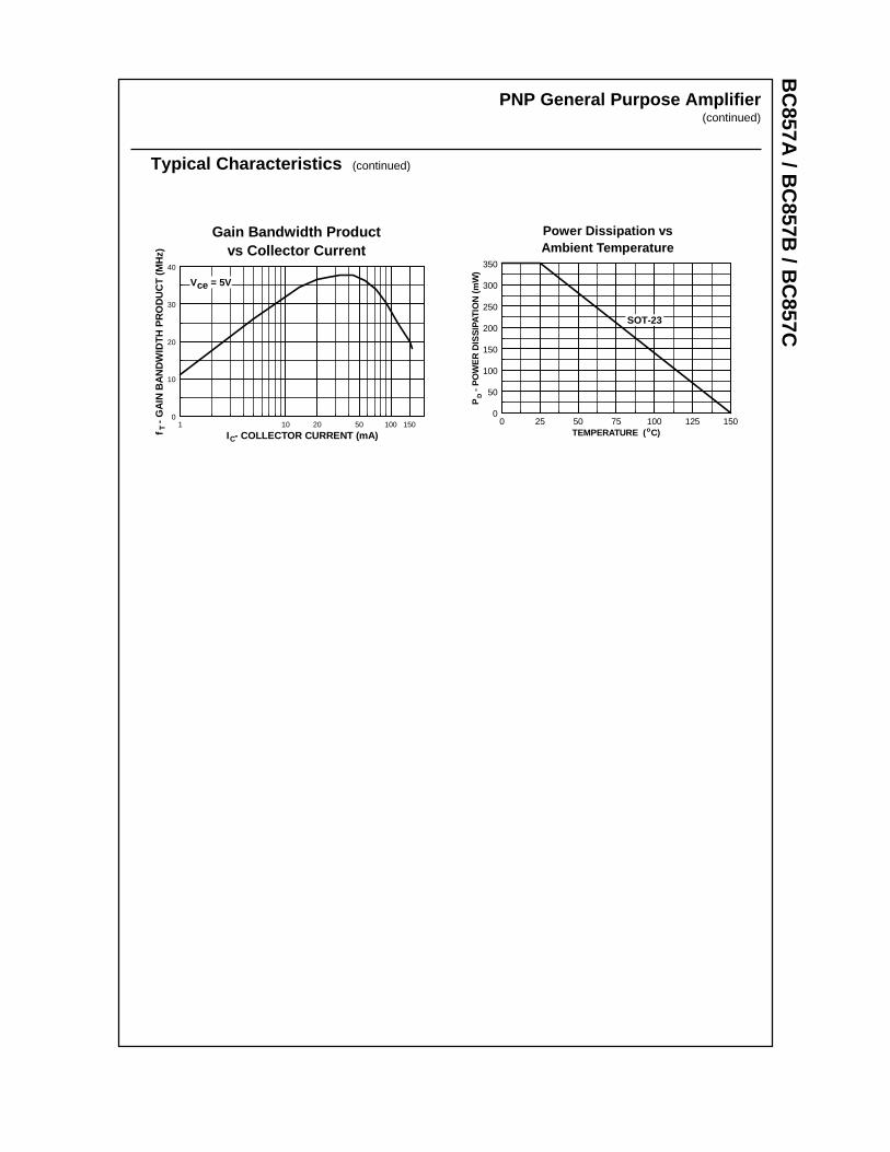
BC
857A / B
C857B
/ BC
857CPNP General Purpose Amplifier
(continued)
Typical Characteristics (continued)
Gain Bandwidth Productvs Collector Current
P 68
1 10 20 50 100 1500
10
20
30
40
I - COLLECTOR CURRENT (mA)f -
GA
IN B
AN
DW
IDT
H P
RO
DU
CT
(M
Hz)
C
T
V = 5Vce
Power Dissipation vsAmbient Temperature
0 25 50 75 100 125 1500
50
100
150
200
250
300
350
TEMPERATURE ( C)
P
- P
OW
ER
DIS
SIP
ATIO
N (
mW
)D
o
SOT-23

TRADEMARKS
ACEx™CoolFET™CROSSVOLT™E2CMOSTM
FACT™FACT Quiet Series™FAST®
FASTr™GTO™HiSeC™
The following are registered and unregistered trademarks Fairchild Semiconductor owns or is authorized to use and isnot intended to be an exhaustive list of all such trademarks.
LIFE SUPPORT POLICY
FAIRCHILD’S PRODUCTS ARE NOT AUTHORIZED FOR USE AS CRITICAL COMPONENTS IN LIFE SUPPORTDEVICES OR SYSTEMS WITHOUT THE EXPRESS WRITTEN APPROVAL OF FAIRCHILD SEMICONDUCTOR CORPORATION.As used herein:
ISOPLANAR™MICROWIRE™POP™PowerTrench™QS™Quiet Series™SuperSOT™-3SuperSOT™-6SuperSOT™-8TinyLogic™
1. Life support devices or systems are devices orsystems which, (a) are intended for surgical implant intothe body, or (b) support or sustain life, or (c) whosefailure to perform when properly used in accordancewith instructions for use provided in the labeling, can bereasonably expected to result in significant injury to theuser.
2. A critical component is any component of a lifesupport device or system whose failure to perform canbe reasonably expected to cause the failure of the lifesupport device or system, or to affect its safety oreffectiveness.
PRODUCT STATUS DEFINITIONS
Definition of Terms
Datasheet Identification Product Status Definition
Advance Information
Preliminary
No Identification Needed
Obsolete
This datasheet contains the design specifications forproduct development. Specifications may change inany manner without notice.
This datasheet contains preliminary data, andsupplementary data will be published at a later date.Fairchild Semiconductor reserves the right to makechanges at any time without notice in order to improvedesign.
This datasheet contains final specifications. FairchildSemiconductor reserves the right to make changes atany time without notice in order to improve design.
This datasheet contains specifications on a productthat has been discontinued by Fairchild semiconductor.The datasheet is printed for reference information only.
Formative orIn Design
First Production
Full Production
Not In Production
DISCLAIMER
FAIRCHILD SEMICONDUCTOR RESERVES THE RIGHT TO MAKE CHANGES WITHOUT FURTHERNOTICE TO ANY PRODUCTS HEREIN TO IMPROVE RELIABILITY, FUNCTION OR DESIGN. FAIRCHILDDOES NOT ASSUME ANY LIABILITY ARISING OUT OF THE APPLICATION OR USE OF ANY PRODUCTOR CIRCUIT DESCRIBED HEREIN; NEITHER DOES IT CONVEY ANY LICENSE UNDER ITS PATENTRIGHTS, NOR THE RIGHTS OF OTHERS.
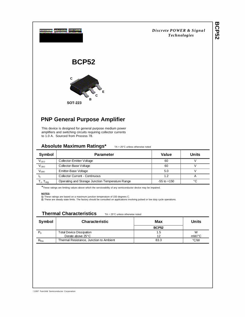
BC
P52
PNP General Purpose Amplifier
Absolute Maximum Ratings* TA = 25°C unless otherwise noted
*These ratings are limiting values above which the serviceability of any semiconductor device may be impaired.
NOTES:1) These ratings are based on a maximum junction temperature of 150 degrees C.2) These are steady state limits. The factory should be consulted on applications involving pulsed or low duty cycle operations.
Thermal Characteristics TA = 25°C unless otherwise noted
BCP52
This device is designed for general purpose medium poweramplifiers and switching circuits requiring collector currentsto 1.0 A. Sourced from Process 78.
BC
C
SOT-223
E
Symbol Parameter Value Units
VCEO Collector-Emitter Voltage 60 V
VCBO Collector-Base Voltage 60 V
VEBO Emitter-Base Voltage 5.0 V
IC Collector Current - Continuous 1.2 A
TJ, Tstg Operating and Storage Junction Temperature Range -55 to +150 °C
Symbol Characteristic Max UnitsBCP52
PD Total Device DissipationDerate above 25°C
1.512
WmW/°C
RθJA Thermal Resistance, Junction to Ambient 83.3 °C/W
Discrete POWER & SignalTechnologies
1997 Fairchild Semiconductor Corporation
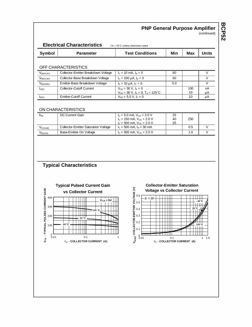
BC
P52
PNP General Purpose Amplifier(continued)
Electrical Characteristics TA = 25°C unless otherwise noted
OFF CHARACTERISTICS
Symbol Parameter Test Conditions Min Max Units
V(BR)CEO Collector-Emitter Breakdown Voltage IC = 10 mA, IB = 0 60 V
V(BR)CBO Collector-Base Breakdown Voltage IC = 100 µA, IE = 0 60 V
V(BR)EBO Emitter-Base Breakdown Voltage IE = 10 µA, IC = 0 5.0 V
ICBO Collector-Cutoff Current VCB = 30 V, IE = 0VCB = 30 V, IE = 0, TA = 125°C
10010
nAµA
IEBO Emitter-Cutoff Current VEB = 5.0 V, IC = 0 10 µA
ON CHARACTERISTICShFE DC Current Gain IC = 5.0 mA, VCE = 2.0 V
IC = 150 mA, VCE = 2.0 VIC = 500 mA, VCE = 2.0 V
254025
250
VCE(sat) Collector-Emitter Saturation Voltage IC = 500 mA, IB = 50 mA 0.5 V
VBE(on) Base-Emitter On Voltage IC = 500 mA, VCE = 2.0 V 1.0 V
Typical Characteristics
Collector-Emitter SaturationVoltage vs Collector Current
P 8
0.01 0.1 1 1.50
0.1
0.2
0.3
0.4
0.5
0.6
I - COLLECTOR CURRENT (A)V
-
CO
LLE
CT
OR
-EM
ITT
ER
VO
LTA
GE
(V
)C
ESA
T
C
ββ = 10
125 ºC
- 40 ºC
25 °C
Typical Pulsed Current Gain
vs Collector Current
0.01 0.1 10
100
200
300
400
I - COLLECTOR CURRENT (A)h
-
TY
PIC
AL
PU
LSE
D C
UR
RE
NT
GA
INF
E
- 40 ºC
25 °C
C
V = 5VCE
125 °C
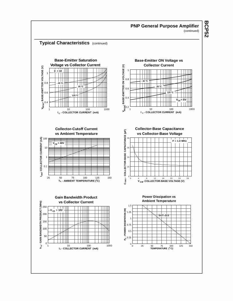
BC
P52
PNP General Purpose Amplifier(continued)
Typical Characteristics (continued)
Base-Emitter ON Voltage vsCollector Current
P 8
1 10 100 10000.2
0.4
0.6
0.8
1
I - COLLECTOR CURRENT (mA)V
-
BA
SE
-EM
ITT
ER
ON
VO
LTA
GE
(V
)B
E(O
N)
125 ºC
- 40 ºC
25 °C
C
V = 5VCE
Collector-Cutoff Currentvs Ambient Temperature
P 8
25 50 75 100 125 150
0.1
1
10
100
T - AMBIENT TEMPERATURE ( C)
I
- C
OLL
EC
TO
R C
UR
RE
NT
(nA
)
A
V = 40VCB
º
CB
O
Base-Emitter SaturationVoltage vs Collector Current
P 78
1 10 100 1000
0.4
0.6
0.8
1
I - COLLECTOR CURRENT (mA)
V
-
BA
SE
-EM
ITT
ER
VO
LTA
GE
(V
)B
ESA
T
C
ββ = 10
125 ºC
- 40 ºC
25 °C
Collector-Base Capacitancevs Collector-Base Voltage
Pr 78
0 4 8 12 16 20 24 280
10
20
30
40
V - COLLECTOR-BASE VOLTAGE (V)
C
-
CO
LLE
CT
OR
-BA
SE
CA
PA
CIT
AN
CE
(pF
)
CBOB
O
F = 1.0 MHz
Gain Bandwidth Productvs Collector Current
1 10 100 10000
50
100
150
200
250
I - COLLECTOR CURRENT (mA)h
- G
AIN
BA
ND
WID
TH P
RO
DU
CT
(M
Hz)
C
FE
V = 10VCE
Power Dissipation vsAmbient Temperature
0 25 50 75 100 125 1500
0.25
0.5
0.75
1
1.25
1.5
TEMPERATURE ( C)
P
- PO
WE
R D
ISSI
PATI
ON
(W)
D
o
SOT-223

TRADEMARKS
ACEx™CoolFET™CROSSVOLT™E2CMOSTM
FACT™FACT Quiet Series™FAST®
FASTr™GTO™HiSeC™
The following are registered and unregistered trademarks Fairchild Semiconductor owns or is authorized to use and isnot intended to be an exhaustive list of all such trademarks.
LIFE SUPPORT POLICY
FAIRCHILD’S PRODUCTS ARE NOT AUTHORIZED FOR USE AS CRITICAL COMPONENTS IN LIFE SUPPORTDEVICES OR SYSTEMS WITHOUT THE EXPRESS WRITTEN APPROVAL OF FAIRCHILD SEMICONDUCTOR CORPORATION.As used herein:
ISOPLANAR™MICROWIRE™POP™PowerTrench™QS™Quiet Series™SuperSOT™-3SuperSOT™-6SuperSOT™-8TinyLogic™
1. Life support devices or systems are devices orsystems which, (a) are intended for surgical implant intothe body, or (b) support or sustain life, or (c) whosefailure to perform when properly used in accordancewith instructions for use provided in the labeling, can bereasonably expected to result in significant injury to theuser.
2. A critical component is any component of a lifesupport device or system whose failure to perform canbe reasonably expected to cause the failure of the lifesupport device or system, or to affect its safety oreffectiveness.
PRODUCT STATUS DEFINITIONS
Definition of Terms
Datasheet Identification Product Status Definition
Advance Information
Preliminary
No Identification Needed
Obsolete
This datasheet contains the design specifications forproduct development. Specifications may change inany manner without notice.
This datasheet contains preliminary data, andsupplementary data will be published at a later date.Fairchild Semiconductor reserves the right to makechanges at any time without notice in order to improvedesign.
This datasheet contains final specifications. FairchildSemiconductor reserves the right to make changes atany time without notice in order to improve design.
This datasheet contains specifications on a productthat has been discontinued by Fairchild semiconductor.The datasheet is printed for reference information only.
Formative orIn Design
First Production
Full Production
Not In Production
DISCLAIMER
FAIRCHILD SEMICONDUCTOR RESERVES THE RIGHT TO MAKE CHANGES WITHOUT FURTHERNOTICE TO ANY PRODUCTS HEREIN TO IMPROVE RELIABILITY, FUNCTION OR DESIGN. FAIRCHILDDOES NOT ASSUME ANY LIABILITY ARISING OUT OF THE APPLICATION OR USE OF ANY PRODUCTOR CIRCUIT DESCRIBED HEREIN; NEITHER DOES IT CONVEY ANY LICENSE UNDER ITS PATENTRIGHTS, NOR THE RIGHTS OF OTHERS.
BC
P54
NPN General Purpose Amplifier
Absolute Maximum Ratings* TA = 25°C unless otherwise noted
*These ratings are limiting values above which the serviceability of any semiconductor device may be impaired.
NOTES:1) These ratings are based on a maximum junction temperature of 150 degrees C.2) These are steady state limits. The factory should be consulted on applications involving pulsed or low duty cycle operations.
Thermal Characteristics TA = 25°C unless otherwise noted
BCP54
This device is designed for general purpose medium poweramplifiers and switching circuits requiring collector currentsto 1.2 A. Sourced from Process 38.
Symbol Parameter Value UnitsVCEO Collector-Emitter Voltage 45 V
VCBO Collector-Base Voltage 45 V
VEBO Emitter-Base Voltage 5.0 V
IC Collector Current - Continuous 1.5 A
TJ, Tstg Operating and Storage Junction Temperature Range -55 to +150 °C
BC
C
SOT-223
E
Symbol Characteristic Max UnitsBCP54
PD Total Device DissipationDerate above 25°C
1.512
WmW/°C
RθJA Thermal Resistance, Junction to Ambient 83.3 °C/W
Discrete POWER & SignalTechnologies
ã 1997 Fairchild Semiconductor Corporation
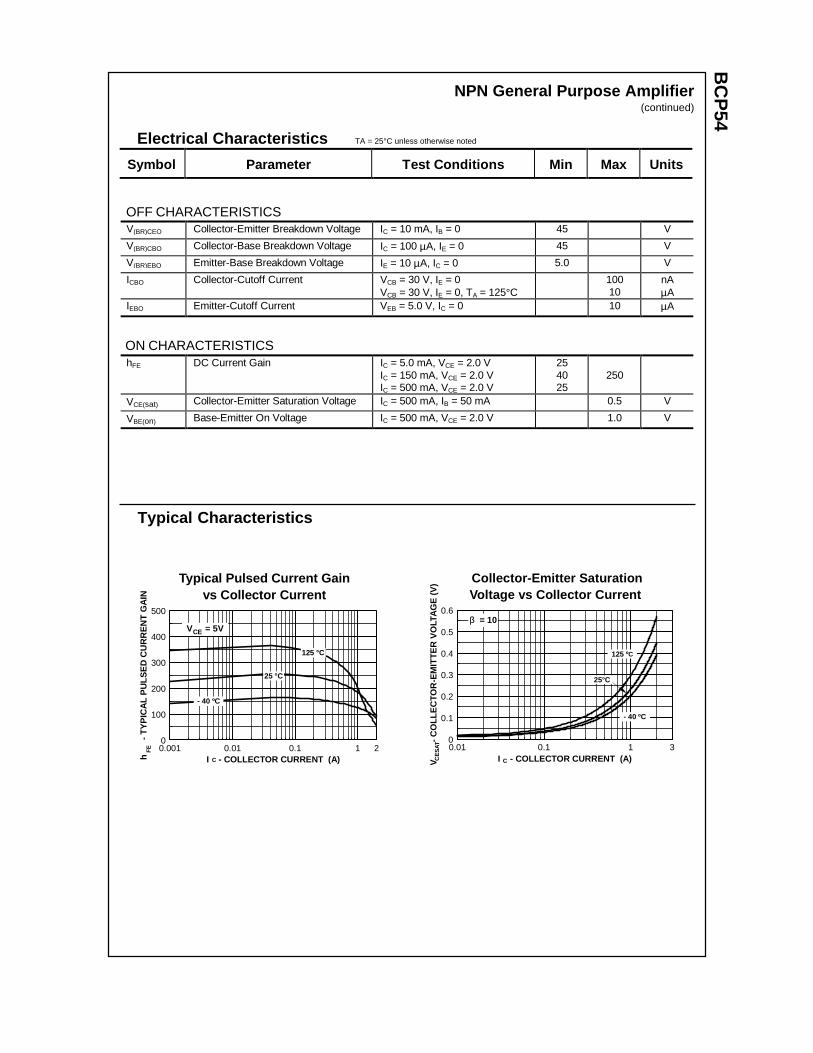
BC
P54
NPN General Purpose Amplifier(continued)
Electrical Characteristics TA = 25°C unless otherwise noted
OFF CHARACTERISTICS
Symbol Parameter Test C onditions Min Max Units
V(BR)CEO Collector-Emitter Breakdown Voltage IC = 10 mA, IB = 0 45 V
V(BR)CBO Collector-Base Breakdown Voltage IC = 100 µA, IE = 0 45 V
V(BR)EBO Emitter-Base Breakdown Voltage IE = 10 µA, IC = 0 5.0 V
ICBO Collector-Cutoff Current VCB = 30 V, IE = 0VCB = 30 V, IE = 0, TA = 125°C
10010
nAµA
IEBO Emitter-Cutoff Current VEB = 5.0 V, IC = 0 10 µA
ON CHARACTERISTICShFE DC Current Gain IC = 5.0 mA, VCE = 2.0 V
IC = 150 mA, VCE = 2.0 VIC = 500 mA, VCE = 2.0 V
254025
250
VCE(sat) Collector-Emitter Saturation Voltage IC = 500 mA, IB = 50 mA 0.5 V
VBE(on) Base-Emitter On Voltage IC = 500 mA, VCE = 2.0 V 1.0 V
Typical Characteristics
Collector-Emitter SaturationVoltage vs Collector Current
0.01 0.1 1 30
0.1
0.2
0.3
0.4
0.5
0.6
I - COLLECTOR CURRENT (A)V
-
CO
LLE
CTO
R-E
MIT
TE
R V
OLT
AG
E (
V)
CE
SAT
C
β = 10
125 ºC
- 40 ºC
25°C
Typical Pulsed Current Gainvs Collector Current
0.001 0.01 0.1 1 20
100
200
300
400
500
I - COLLECTOR CURRENT (A)h
- T
YP
ICA
L P
ULS
ED
CU
RR
EN
T G
AIN
FE
- 40 ºC
25 °C
C
V = 5VCE
125 °C
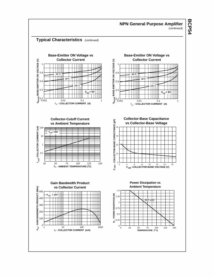
BC
P54
NPN General Purpose Amplifier(continued)
Typical Characteristics (continued)
Base-Emitter ON Voltage vsCollector Current
P 38
0.001 0.01 0.1 10.2
0.4
0.6
0.8
1
I - COLLECTOR CURRENT (A)V
-
BA
SE
-EM
ITT
ER
ON
VO
LTA
GE
(V
)B
E(O
N)
C
V = 5VCE
125 ºC
- 40 ºC
25°C
Base-Emitter ON Voltage vsCollector Current
P
0.001 0.01 0.1 10.2
0.4
0.6
0.8
1
I - COLLECTOR CURRENT (A)V
-
BA
SE
-EM
ITT
ER
ON
VO
LTA
GE
(V)
BE
(ON
)
C
V = 5VCE
125 ºC
- 40 ºC
25°C
Collector-Cutoff Currentvs Ambient Temperature
25 50 75 100 125 150
0.1
1
10
100
T - AMBIENT TEMPERATURE ( C)
I
- C
OLL
EC
TOR
CU
RR
EN
T (
nA)
A
V = 40VCB
º
CB
O
Collector-Base Capacitancevs Collector-Base Voltage
Pr 38
0 4 8 12 16 20 24 280
10
20
30
40
V - COLLECTOR-BASE VOLTAGE (V)
C
-
CO
LLE
CTO
R-B
AS
E C
APA
CIT
AN
CE
(pF
)
CBOB
O
Gain Bandwidth Productvs Collector Current
1 10 100 10000
100
200
300
400
500
I - COLLECTOR CURRENT (mA)h
- G
AIN
BA
ND
WID
TH
PR
OD
UC
T (
MH
z)
C
FE
V = 10VCE
Power Dissipation vsAmbient Temperature
0 25 50 75 100 125 1500
0.25
0.5
0.75
1
1.25
1.5
TEMPERATURE ( C)
P
- P
OW
ER
DIS
SIP
ATIO
N (
W)
D
o
SOT-223

TRADEMARKS
ACEx™CoolFET™CROSSVOLT™E2CMOSTM
FACT™FACT Quiet Series™FAST®
FASTr™GTO™HiSeC™
The following are registered and unregistered trademarks Fairchild Semiconductor owns or is authorized to use and isnot intended to be an exhaustive list of all such trademarks.
LIFE SUPPORT POLICY
FAIRCHILD’S PRODUCTS ARE NOT AUTHORIZED FOR USE AS CRITICAL COMPONENTS IN LIFE SUPPORTDEVICES OR SYSTEMS WITHOUT THE EXPRESS WRITTEN APPROVAL OF FAIRCHILD SEMICONDUCTOR CORPORATION.As used herein:
ISOPLANAR™MICROWIRE™POP™PowerTrench™QS™Quiet Series™SuperSOT™-3SuperSOT™-6SuperSOT™-8TinyLogic™
1. Life support devices or systems are devices orsystems which, (a) are intended for surgical implant intothe body, or (b) support or sustain life, or (c) whosefailure to perform when properly used in accordancewith instructions for use provided in the labeling, can bereasonably expected to result in significant injury to theuser.
2. A critical component is any component of a lifesupport device or system whose failure to perform canbe reasonably expected to cause the failure of the lifesupport device or system, or to affect its safety oreffectiveness.
PRODUCT STATUS DEFINITIONS
Definition of Terms
Datasheet Identification Product Status Definition
Advance Information
Preliminary
No Identification Needed
Obsolete
This datasheet contains the design specifications forproduct development. Specifications may change inany manner without notice.
This datasheet contains preliminary data, andsupplementary data will be published at a later date.Fairchild Semiconductor reserves the right to makechanges at any time without notice in order to improvedesign.
This datasheet contains final specifications. FairchildSemiconductor reserves the right to make changes atany time without notice in order to improve design.
This datasheet contains specifications on a productthat has been discontinued by Fairchild semiconductor.The datasheet is printed for reference information only.
Formative orIn Design
First Production
Full Production
Not In Production
DISCLAIMER
FAIRCHILD SEMICONDUCTOR RESERVES THE RIGHT TO MAKE CHANGES WITHOUT FURTHERNOTICE TO ANY PRODUCTS HEREIN TO IMPROVE RELIABILITY, FUNCTION OR DESIGN. FAIRCHILDDOES NOT ASSUME ANY LIABILITY ARISING OUT OF THE APPLICATION OR USE OF ANY PRODUCTOR CIRCUIT DESCRIBED HEREIN; NEITHER DOES IT CONVEY ANY LICENSE UNDER ITS PATENTRIGHTS, NOR THE RIGHTS OF OTHERS.
BC
V26
PNP Darlington Transistor
Absolute Maximum Ratings* TA = 25°C unless otherwise noted
*These ratings are limiting values above which the serviceability of any semiconductor device may be impaired.
NOTES:1) These ratings are based on a maximum junction temperature of 150 degrees C.2) These are steady state limits. The factory should be consulted on applications involving pulsed or low duty cycle operations.
Thermal Characteristics TA = 25°C unless otherwise noted
BCV26
This device is designed for applications requiring extremely highcurrent gain at currents to 800 mA. Sourced from Process 61.
Symbol Parameter Value UnitsVCEO Collector-Emitter Voltage 30 V
VCBO Collector-Base Voltage 40 V
VEBO Emitter-Base Voltage 10 V
IC Collector Current - Continuous 1.2 A
TJ, Tstg Operating and Storage Junction Temperature Range -55 to +150 °C
Symbol Characteristic Max Units*BCV26
PD Total Device DissipationDerate above 25°C
3502.8
mWmW/°C
RθJA Thermal Resistance, Junction to Ambient 357 °C/W
C
B
E
SOT-23Mark: FD
*Device mounted on FR-4 PCB 40 mm X 40 mm X 1.5 mm.
Discrete POWER & SignalTechnologies
ã 1997 Fairchild Semiconductor Corporation
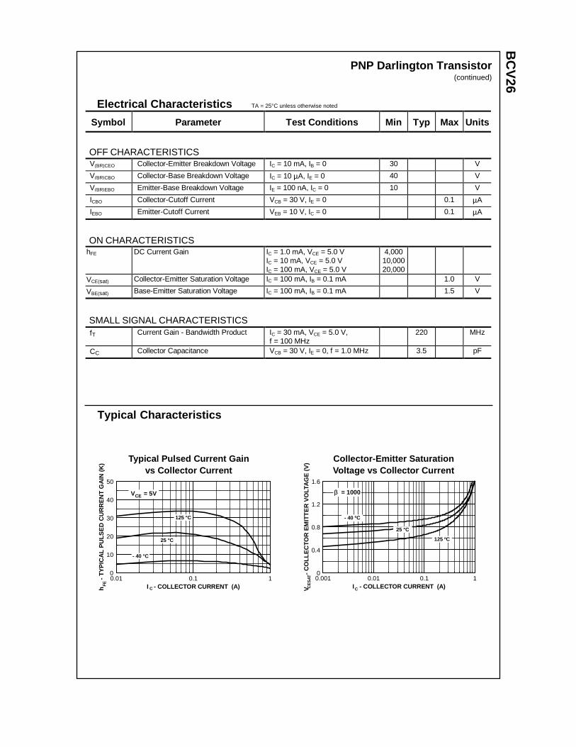
BC
V26
Electrical Characteristics TA = 25°C unless otherwise noted
OFF CHARACTERISTICS
Symbol Parameter Test C onditions Min Typ Max Units
V(BR)CEO Collector-Emitter Breakdown Voltage IC = 10 mA, IB = 0 30 V
V(BR)CBO Collector-Base Breakdown Voltage IC = 10 µA, IE = 0 40 V
V(BR)EBO Emitter-Base Breakdown Voltage IE = 100 nA, IC = 0 10 V
ICBO Collector-Cutoff Current VCB = 30 V, IE = 0 0.1 µA
IEBO Emitter-Cutoff Current VEB = 10 V, IC = 0 0.1 µA
ON CHARACTERISTICShFE DC Current Gain IC = 1.0 mA, VCE = 5.0 V
IC = 10 mA, VCE = 5.0 VIC = 100 mA, VCE = 5.0 V
4,00010,00020,000
VCE(sat) Collector-Emitter Saturation Voltage IC = 100 mA, IB = 0.1 mA 1.0 V
VBE(sat) Base-Emitter Saturation Voltage IC = 100 mA, IB = 0.1 mA 1.5 V
SMALL SIGNAL CHARACTERISTICSfT Current Gain - Bandwidth Product IC = 30 mA, VCE = 5.0 V,
f = 100 MHz220 MHz
CC Collector Capacitance VCB = 30 V, IE = 0, f = 1.0 MHz 3.5 pF
PNP Darlington Transistor(continued)
Typical Characteristics
Collector-Emitter SaturationVoltage vs Collector Current
0.001 0.01 0.1 10
0.4
0.8
1.2
1.6
I - COLLECTOR CURRENT (A)V
-
CO
LLE
CTO
R E
MIT
TE
R V
OLT
AG
E (
V)
CCE
SAT
β = 1000
25 °C
- 40 ºC
125 ºC
Typical Pulsed Current Gainvs Collector Current
0.01 0.1 10
10
20
30
40
50
I - COLLECTOR CURRENT (A)h
- T
YP
ICA
L P
ULS
ED
CU
RR
EN
T G
AIN
(K
)
C
FE
125 °C
25 °C
- 40 °C
V = 5VCE
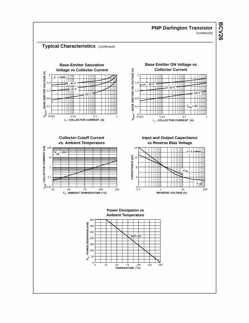
BC
V26
PNP Darlington Transistor(continued)
Typical Characteristics (continued)
Base-Emitter SaturationVoltage vs Collector Current
0.001 0.01 0.1 10
0.4
0.8
1.2
1.6
2
I - COLLECTOR CURRENT (A)
V
-
BA
SE
EM
ITT
ER
VO
LTA
GE
(V
)
C
BE
SAT
25 °C
- 40 ºC
125 ºC
β = 1000
Base Emitter ON Voltage vsCollector Current
0.001 0.01 0.1 10
0.4
0.8
1.2
1.6
2
I - COLLECTOR CURRENT (A)V
-
BA
SE
EM
ITT
ER
ON
VO
LTA
GE
(V
)
C
BE
ON
V = 5VCE
25 °C
- 40 ºC
125 ºC
Collector-Cutoff Currentvs. Ambient Temperature
25 50 75 100 1250.01
0.1
1
10
100
T - AMBIENT TEMPERATURE ( C)
I
- C
OLL
EC
TOR
CU
RR
EN
T (
nA)
A
CB
O
º
V = 15VCB
Input and Output Capacitancevs Reverse Bias Voltage
0.1 1 10 1000
4
8
12
16
REVERSE VOLTAGE (V)
CA
PA
CIT
AN
CE
(pF
)
C
f = 1.0 MHz
ib
C ob
Power Dissipation vsAmbient Temperature
0 25 50 75 100 125 1500
50
100
150
200
250
300
350
TEMPERATURE ( C)
P
- P
OW
ER
DIS
SIP
ATIO
N (
mW
)D
o
SOT-23

TRADEMARKS
ACEx™CoolFET™CROSSVOLT™E2CMOSTM
FACT™FACT Quiet Series™FAST®
FASTr™GTO™HiSeC™
The following are registered and unregistered trademarks Fairchild Semiconductor owns or is authorized to use and isnot intended to be an exhaustive list of all such trademarks.
LIFE SUPPORT POLICY
FAIRCHILD’S PRODUCTS ARE NOT AUTHORIZED FOR USE AS CRITICAL COMPONENTS IN LIFE SUPPORTDEVICES OR SYSTEMS WITHOUT THE EXPRESS WRITTEN APPROVAL OF FAIRCHILD SEMICONDUCTOR CORPORATION.As used herein:
ISOPLANAR™MICROWIRE™POP™PowerTrench™QS™Quiet Series™SuperSOT™-3SuperSOT™-6SuperSOT™-8TinyLogic™
1. Life support devices or systems are devices orsystems which, (a) are intended for surgical implant intothe body, or (b) support or sustain life, or (c) whosefailure to perform when properly used in accordancewith instructions for use provided in the labeling, can bereasonably expected to result in significant injury to theuser.
2. A critical component is any component of a lifesupport device or system whose failure to perform canbe reasonably expected to cause the failure of the lifesupport device or system, or to affect its safety oreffectiveness.
PRODUCT STATUS DEFINITIONS
Definition of Terms
Datasheet Identification Product Status Definition
Advance Information
Preliminary
No Identification Needed
Obsolete
This datasheet contains the design specifications forproduct development. Specifications may change inany manner without notice.
This datasheet contains preliminary data, andsupplementary data will be published at a later date.Fairchild Semiconductor reserves the right to makechanges at any time without notice in order to improvedesign.
This datasheet contains final specifications. FairchildSemiconductor reserves the right to make changes atany time without notice in order to improve design.
This datasheet contains specifications on a productthat has been discontinued by Fairchild semiconductor.The datasheet is printed for reference information only.
Formative orIn Design
First Production
Full Production
Not In Production
DISCLAIMER
FAIRCHILD SEMICONDUCTOR RESERVES THE RIGHT TO MAKE CHANGES WITHOUT FURTHERNOTICE TO ANY PRODUCTS HEREIN TO IMPROVE RELIABILITY, FUNCTION OR DESIGN. FAIRCHILDDOES NOT ASSUME ANY LIABILITY ARISING OUT OF THE APPLICATION OR USE OF ANY PRODUCTOR CIRCUIT DESCRIBED HEREIN; NEITHER DOES IT CONVEY ANY LICENSE UNDER ITS PATENTRIGHTS, NOR THE RIGHTS OF OTHERS.
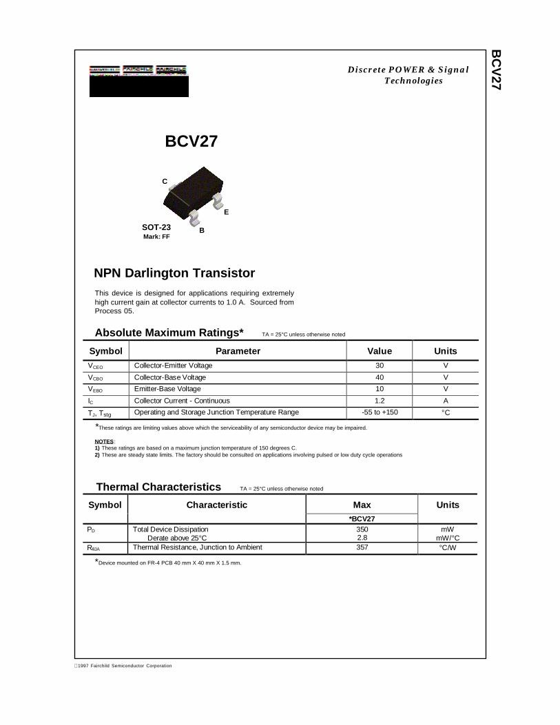
BC
V27
C
B
E
NPN Darlington TransistorThis device is designed for applications requiring extremelyhigh current gain at collector currents to 1.0 A. Sourced fromProcess 05.
Absolute Maximum Ratings* TA = 25°C unless otherwise noted
*These ratings are limiting values above which the serviceability of any semiconductor device may be impaired.
NOTES:1) These ratings are based on a maximum junction temperature of 150 degrees C.2) These are steady state limits. The factory should be consulted on applications involving pulsed or low duty cycle operations
Thermal Characteristics TA = 25°C unless otherwise noted
BCV27
Symbol Parameter Value Units
VCEO Collector-Emitter Voltage 30 V
VCBO Collector-Base Voltage 40 V
VEBO Emitter-Base Voltage 10 V
IC Collector Current - Continuous 1.2 A
TJ, Tstg Operating and Storage Junction Temperature Range -55 to +150 °C
Symbol Characteristic Max Units*BCV27
PD Total Device DissipationDerate above 25°C
3502.8
mWmW/°C
RθJA Thermal Resistance, Junction to Ambient 357 °C/W
SOT-23Mark: FF
*Device mounted on FR-4 PCB 40 mm X 40 mm X 1.5 mm.
Discrete POWER & SignalTechnologies
1997 Fairchild Semiconductor Corporation
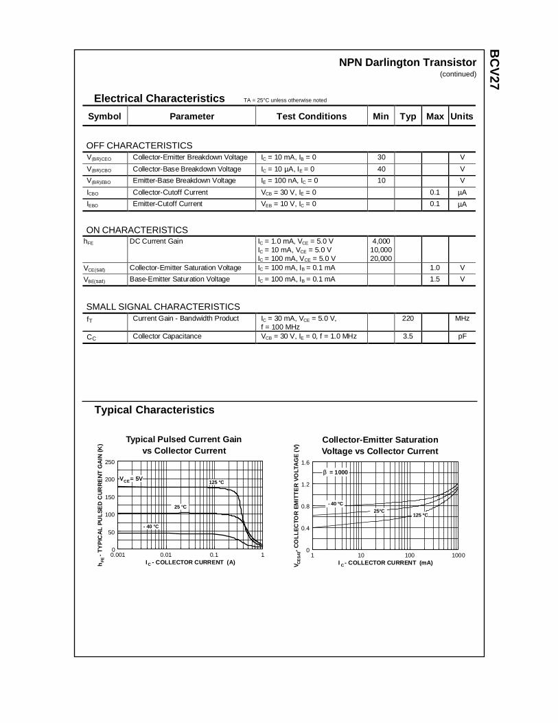
BC
V27
Electrical Characteristics TA = 25°C unless otherwise noted
OFF CHARACTERISTICS
Symbol Parameter Test Conditions Min Typ Max Units
V(BR)CEO Collector-Emitter Breakdown Voltage IC = 10 mA, IB = 0 30 V
V(BR)CBO Collector-Base Breakdown Voltage IC = 10 µA, IE = 0 40 V
V(BR)EBO Emitter-Base Breakdown Voltage IE = 100 nA, IC = 0 10 V
ICBO Collector-Cutoff Current VCB = 30 V, IE = 0 0.1 µA
IEBO Emitter-Cutoff Current VEB = 10 V, IC = 0 0.1 µA
ON CHARACTERISTICShFE DC Current Gain IC = 1.0 mA, VCE = 5.0 V
IC = 10 mA, VCE = 5.0 VIC = 100 mA, VCE = 5.0 V
4,00010,00020,000
VCE(sat) Collector-Emitter Saturation Voltage IC = 100 mA, IB = 0.1 mA 1.0 V
VBE(sat) Base-Emitter Saturation Voltage IC = 100 mA, IB = 0.1 mA 1.5 V
SMALL SIGNAL CHARACTERISTICSfT Current Gain - Bandwidth Product IC = 30 mA, VCE = 5.0 V,
f = 100 MHz220 MHz
CC Collector Capacitance VCB = 30 V, IE = 0, f = 1.0 MHz 3.5 pF
NPN Darlington Transistor(continued)
Typical Characteristics
Typical Pulsed Current Gainvs Collector Current
0.001 0.01 0.1 10
50
100
150
200
250
I - COLLECTOR CURRENT (A)h
- T
YP
ICA
L P
ULS
ED
CU
RR
EN
T G
AIN
(K
)
C
FE
25 °C
125 °C
- 40 °C
V = 5VCE
Collector-Emitter SaturationVoltage vs Collector Current
P 0
1 10 100 10000
0.4
0.8
1.2
1.6
I - COLLECTOR CURRENT (mA)V
-
CO
LLE
CTO
R E
MIT
TE
R V
OLT
AG
E (
V)
C
CE
SAT
25°C - 40 ºC
125 ºC
ββ = 1000
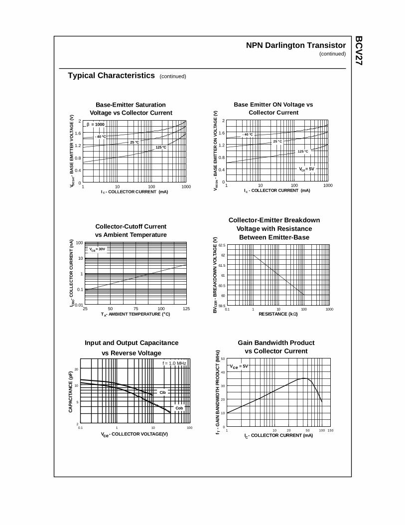
BC
V27
NPN Darlington Transistor(continued)
Typical Characteristics (continued)
Base-Emitter SaturationVoltage vs Collector Current
P 05
1 10 100 10000
0.4
0.8
1.2
1.6
2
I - COLLECTOR CURRENT (mA)
V
-
BA
SE
EM
ITT
ER
VO
LTA
GE
(V
)
C
BE
SAT
25 °C
- 40 ºC
125 ºC
ββ = 1000
Base Emitter ON Voltage vsCollector Current
P 0
1 10 100 10000
0.4
0.8
1.2
1.6
2
I - COLLECTOR CURRENT (mA)V
-
BA
SE
EM
ITT
ER
ON
VO
LTA
GE
(V
)
C
BE
ON
V = 5VCE
- 40 ºC
25 °C
125 ºC
Collector-Emitter BreakdownVoltage with ResistanceBetween Emitter-Base
0.1 1 10 100 100059.5
60
60.5
61
61.5
62
62.5
RESISTANCE (k )BV
- B
RE
AK
DO
WN
VO
LTAG
E (V
)
ΩΩ
CE
R
Collector-Cutoff Currentvs Ambient Temperature
P 0
25 50 75 100 1250.01
0.1
1
10
100
T - AMBIENT TEMPERATURE ( C)
I
- C
OLL
EC
TOR
CU
RR
EN
T (n
A)
A
CB
O
º
V = 30VCB
Input and Output Capacitance
vs Reverse Voltage
P 0
0.1 1 10 1002
5
10
20
V - COLLECTOR VOLTAGE(V)
CA
PAC
ITA
NC
E (
pF)
ce
Cib
Cob
f = 1.0 MHz
Gain Bandwidth Productvs Collector Current
P 05
1 10 20 50 100 1500
10
20
30
40
50
I - COLLECTOR CURRENT (mA)f -
GAI
N B
AND
WID
TH P
RO
DU
CT
(MH
z)
C
T
V = 5Vce
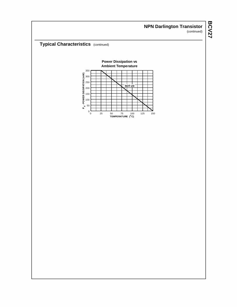
BC
V27
NPN Darlington Transistor(continued)
Typical Characteristics (continued)
Power Dissipation vsAmbient Temperature
0 25 50 75 100 125 1500
50
100
150
200
250
300
350
TEMPERATURE ( C)
P
- PO
WE
R D
ISS
IPAT
ION
(mW
)D
o
SOT-23

TRADEMARKS
ACEx™CoolFET™CROSSVOLT™E2CMOSTM
FACT™FACT Quiet Series™FAST®
FASTr™GTO™HiSeC™
The following are registered and unregistered trademarks Fairchild Semiconductor owns or is authorized to use and isnot intended to be an exhaustive list of all such trademarks.
LIFE SUPPORT POLICY
FAIRCHILD’S PRODUCTS ARE NOT AUTHORIZED FOR USE AS CRITICAL COMPONENTS IN LIFE SUPPORTDEVICES OR SYSTEMS WITHOUT THE EXPRESS WRITTEN APPROVAL OF FAIRCHILD SEMICONDUCTOR CORPORATION.As used herein:
ISOPLANAR™MICROWIRE™POP™PowerTrench™QS™Quiet Series™SuperSOT™-3SuperSOT™-6SuperSOT™-8TinyLogic™
1. Life support devices or systems are devices orsystems which, (a) are intended for surgical implant intothe body, or (b) support or sustain life, or (c) whosefailure to perform when properly used in accordancewith instructions for use provided in the labeling, can bereasonably expected to result in significant injury to theuser.
2. A critical component is any component of a lifesupport device or system whose failure to perform canbe reasonably expected to cause the failure of the lifesupport device or system, or to affect its safety oreffectiveness.
PRODUCT STATUS DEFINITIONS
Definition of Terms
Datasheet Identification Product Status Definition
Advance Information
Preliminary
No Identification Needed
Obsolete
This datasheet contains the design specifications forproduct development. Specifications may change inany manner without notice.
This datasheet contains preliminary data, andsupplementary data will be published at a later date.Fairchild Semiconductor reserves the right to makechanges at any time without notice in order to improvedesign.
This datasheet contains final specifications. FairchildSemiconductor reserves the right to make changes atany time without notice in order to improve design.
This datasheet contains specifications on a productthat has been discontinued by Fairchild semiconductor.The datasheet is printed for reference information only.
Formative orIn Design
First Production
Full Production
Not In Production
DISCLAIMER
FAIRCHILD SEMICONDUCTOR RESERVES THE RIGHT TO MAKE CHANGES WITHOUT FURTHERNOTICE TO ANY PRODUCTS HEREIN TO IMPROVE RELIABILITY, FUNCTION OR DESIGN. FAIRCHILDDOES NOT ASSUME ANY LIABILITY ARISING OUT OF THE APPLICATION OR USE OF ANY PRODUCTOR CIRCUIT DESCRIBED HEREIN; NEITHER DOES IT CONVEY ANY LICENSE UNDER ITS PATENTRIGHTS, NOR THE RIGHTS OF OTHERS.
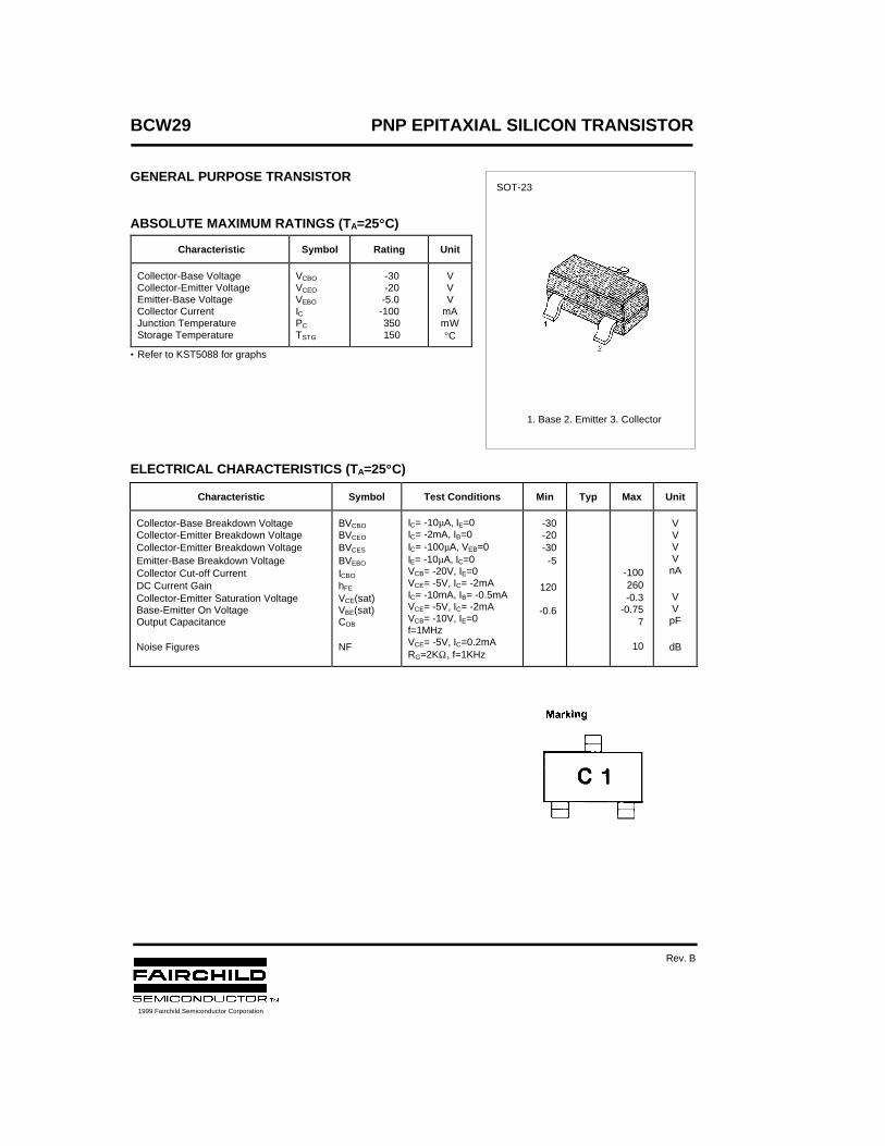
BCW29 PNP EPITAXIAL SILICON TRANSISTOR
GENERAL PURPOSE TRANSISTOR
ABSOLUTE MAXIMUM RATINGS (TA=25°°C)
• Refer to KST5088 for graphs
ELECTRICAL CHARACTERISTICS (TA=25°°C)
Characteristic Symbol Rating Unit
Collector-Base VoltageCollector-Emitter VoltageEmitter-Base VoltageCollector CurrentJunction TemperatureStorage Temperature
VCBO
VCEO
VEBO
ICPC
TSTG
-30 -20 -5.0-100 350 150
VVV
mAmW°C
Characteristic Symbol Test Conditions Min Typ Max Unit
Collector-Base Breakdown VoltageCollector-Emitter Breakdown VoltageCollector-Emitter Breakdown VoltageEmitter-Base Breakdown VoltageCollector Cut-off CurrentDC Current GainCollector-Emitter Saturation VoltageBase-Emitter On VoltageOutput Capacitance
Noise Figures
BVCBO
BVCEO
BVCES
BVEBO
ICBO
hFE
VCE(sat)VBE(sat)COB
NF
IC= -10µA, IE=0IC= -2mA, IB=0IC= -100µA, VEB=0IE= -10µA, IC=0VCB= -20V, IE=0VCE= -5V, IC= -2mAIC= -10mA, IB= -0.5mAVCE= -5V, IC= -2mAVCB= -10V, IE=0f=1MHzVCE= -5V, IC=0.2mARG=2KΩ, f=1KHz
-30-20-30-5
120
-0.6
-100260-0.3
-0.757
10
VVVVnA
VVpF
dB
SOT-23
1. Base 2. Emitter 3. Collector
1999 Fairchild Semiconductor Corporation
Rev. B

TRADEMARKS
ACEx™CoolFET™CROSSVOLT™E2CMOSTM
FACT™FACT Quiet Series™FAST®
FASTr™GTO™HiSeC™
The following are registered and unregistered trademarks Fairchild Semiconductor owns or is authorized to use and isnot intended to be an exhaustive list of all such trademarks.
LIFE SUPPORT POLICY
FAIRCHILD’S PRODUCTS ARE NOT AUTHORIZED FOR USE AS CRITICAL COMPONENTS IN LIFE SUPPORTDEVICES OR SYSTEMS WITHOUT THE EXPRESS WRITTEN APPROVAL OF FAIRCHILD SEMICONDUCTOR CORPORATION.As used herein:
ISOPLANAR™MICROWIRE™POP™PowerTrench™QS™Quiet Series™SuperSOT™-3SuperSOT™-6SuperSOT™-8TinyLogic™
1. Life support devices or systems are devices orsystems which, (a) are intended for surgical implant intothe body, or (b) support or sustain life, or (c) whosefailure to perform when properly used in accordancewith instructions for use provided in the labeling, can bereasonably expected to result in significant injury to theuser.
2. A critical component is any component of a lifesupport device or system whose failure to perform canbe reasonably expected to cause the failure of the lifesupport device or system, or to affect its safety oreffectiveness.
PRODUCT STATUS DEFINITIONS
Definition of Terms
Datasheet Identification Product Status Definition
Advance Information
Preliminary
No Identification Needed
Obsolete
This datasheet contains the design specifications forproduct development. Specifications may change inany manner without notice.
This datasheet contains preliminary data, andsupplementary data will be published at a later date.Fairchild Semiconductor reserves the right to makechanges at any time without notice in order to improvedesign.
This datasheet contains final specifications. FairchildSemiconductor reserves the right to make changes atany time without notice in order to improve design.
This datasheet contains specifications on a productthat has been discontinued by Fairchild semiconductor.The datasheet is printed for reference information only.
Formative orIn Design
First Production
Full Production
Not In Production
DISCLAIMER
FAIRCHILD SEMICONDUCTOR RESERVES THE RIGHT TO MAKE CHANGES WITHOUT FURTHERNOTICE TO ANY PRODUCTS HEREIN TO IMPROVE RELIABILITY, FUNCTION OR DESIGN. FAIRCHILDDOES NOT ASSUME ANY LIABILITY ARISING OUT OF THE APPLICATION OR USE OF ANY PRODUCTOR CIRCUIT DESCRIBED HEREIN; NEITHER DOES IT CONVEY ANY LICENSE UNDER ITS PATENTRIGHTS, NOR THE RIGHTS OF OTHERS.
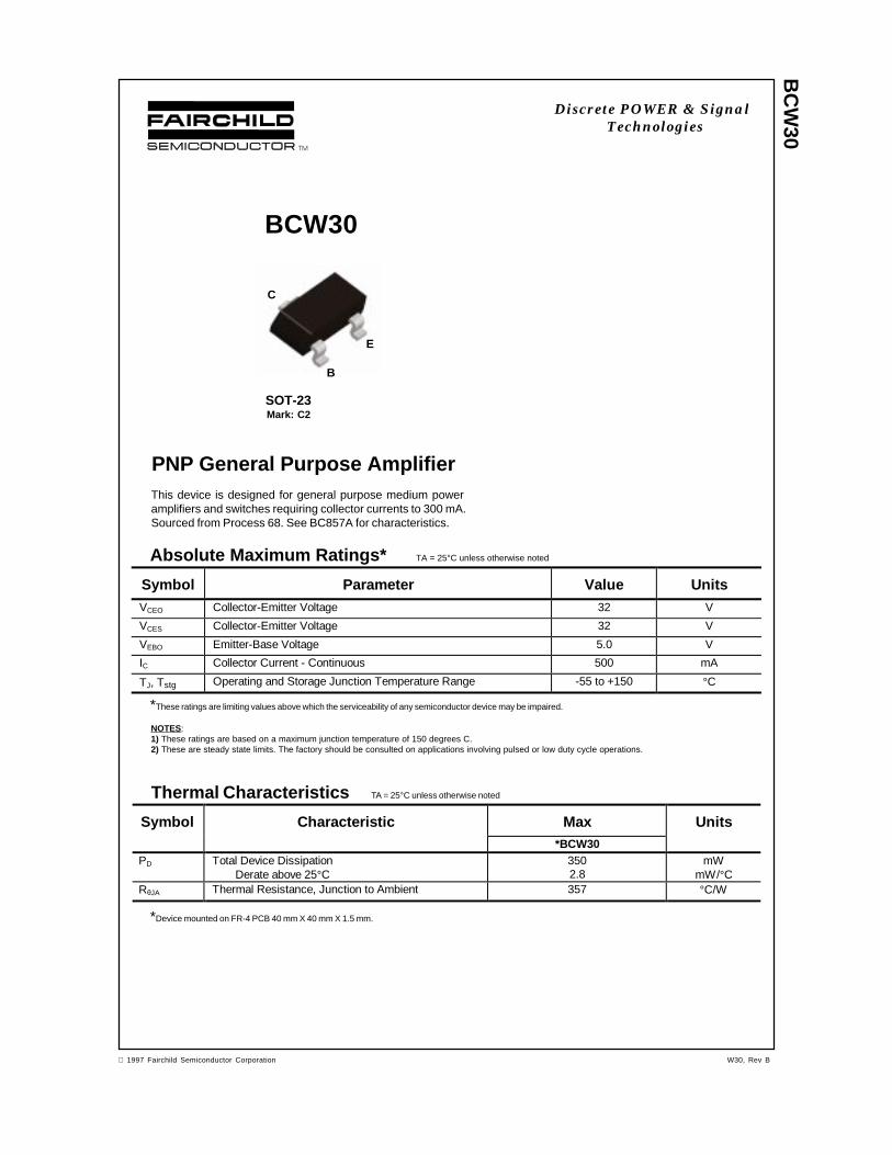
BC
W30
Discrete POWER & SignalTechnologies
Absolute Maximum Ratings* TA = 25°C unless otherwise noted
*These ratings are limiting values above which the serviceability of any semiconductor device may be impaired.
NOTES:1) These ratings are based on a maximum junction temperature of 150 degrees C.2) These are steady state limits. The factory should be consulted on applications involving pulsed or low duty cycle operations.
Symbol Parameter Value UnitsVCEO Collector-Emitter Voltage 32 V
VCES Collector-Emitter Voltage 32 V
VEBO Emitter-Base Voltage 5.0 V
IC Collector Current - Continuous 500 mA
TJ, Tstg Operating and Storage Junction Temperature Range -55 to +150 °C
1997 Fairchild Semiconductor Corporation
PNP General Purpose AmplifierThis device is designed for general purpose medium poweramplifiers and switches requiring collector currents to 300 mA.Sourced from Process 68. See BC857A for characteristics.
Thermal Characteristics TA = 25°C unless otherwise noted
Symbol Characteristic Max Units*BCW30
PD Total Device DissipationDerate above 25°C
3502.8
mWmW/°C
RθJA Thermal Resistance, Junction to Ambient 357 °C/W
*Device mounted on FR-4 PCB 40 mm X 40 mm X 1.5 mm.
BCW30
SOT-23Mark: C2
C
B
E
W30, Rev B
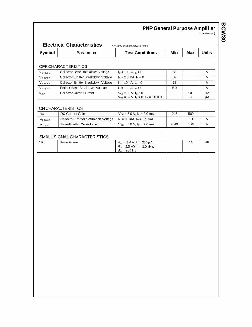
BC
W30
PNP General Purpose Amplifier(continued)
Electrical Characteristics TA = 25°C unless otherwise noted
OFF CHARACTERISTICS
Symbol Parameter Test C onditions Min Max Units
V(BR)CBO Collector-Base Breakdown Voltage IC = 10 µA, IE = 0 32 V
V(BR)CEO Collector-Emitter Breakdown Voltage IC = 2.0 mA, IB = 0 32 V
V(BR)CES Collector-Emitter Breakdown Voltage IC = 10 µA, IE = 0 32 V
V(BR)EBO Emitter-Base Breakdown Voltage IE = 10 µA, IC = 0 5.0 V
ICBO Collector-Cutoff Current VCB = 32 V, IE = 0VCB = 32 V, IE = 0, TA = +100 °C
10010
nAµA
ON CHARACTERISTICShFE DC Current Gain VCE = 5.0 V, IC = 2.0 mA 215 500
VCE(sat) Collector-Emitter Saturation Voltage IC = 10 mA, IB = 0.5 mA 0.30 V
VBE(on) Base-Emitter On Voltage VCE = 5.0 V, IC = 2.0 mA 0.60 0.75 V
SMALL SIGNAL CHARACTERISTICSNF Noise Figure VCE = 5.0 V, IC = 200 µA,
RS = 2.0 kΩ, f = 1.0 kHz,BW = 200 Hz
10 dB
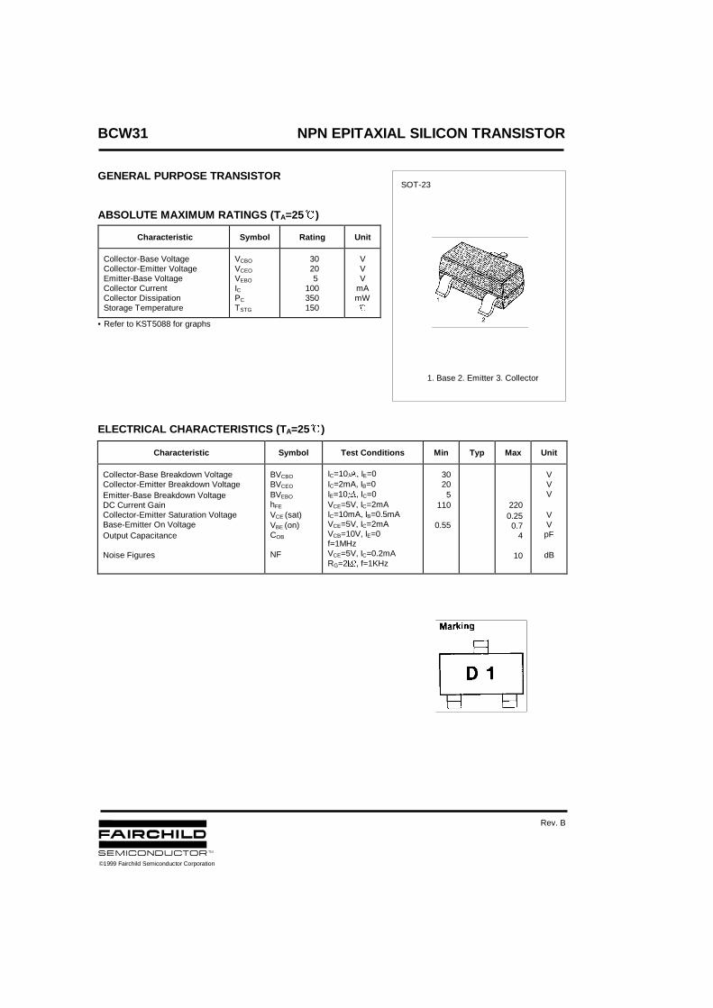
BCW31 NPN EPITAXIAL SILICON TRANSISTOR
GENERAL PURPOSE TRANSISTOR
ABSOLUTE MAXIMUM RATINGS (T A=25&)
• Refer to KST5088 for graphs
ELECTRICAL CHARACTERISTICS (T A=25&)
Characteristic Symbol Rating Unit
Collector-Base VoltageCollector-Emitter VoltageEmitter-Base VoltageCollector CurrentCollector DissipationStorage Temperature
VCBO
VCEO
VEBO
ICPC
TSTG
30 20 5100350150
VVV
mAmW&
Characteristic Symbol Test Conditions Min Typ Max Unit
Collector-Base Breakdown VoltageCollector-Emitter Breakdown VoltageEmitter-Base Breakdown VoltageDC Current GainCollector-Emitter Saturation VoltageBase-Emitter On VoltageOutput Capacitance
Noise Figures
BVCBO
BVCEO
BVEBO
hFE
VCE (sat)VBE (on)COB
NF
IC=10, IE=0IC=2mA, IB=0IE=10, IC=0VCE=5V, IC=2mAIC=10mA, IB=0.5mAVCE=5V, IC=2mAVCB=10V, IE=0f=1MHzVCE=5V, IC=0.2mARG=2, f=1KHz
30205
110
0.55
2200.250.7
4
10
VVV
VVpF
dB
SOT-23
1. Base 2. Emitter 3. Collector
©1999 Fairchild Semiconductor Corporation
Rev. B
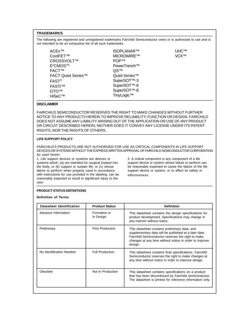
TRADEMARKS
ACEx™CoolFET™CROSSVOLT™E2CMOSTM
FACT™FACT Quiet Series™FAST®
FASTr™GTO™HiSeC™
The following are registered and unregistered trademarks Fairchild Semiconductor owns or is authorized to use and isnot intended to be an exhaustive list of all such trademarks.
LIFE SUPPORT POLICY
FAIRCHILD’S PRODUCTS ARE NOT AUTHORIZED FOR USE AS CRITICAL COMPONENTS IN LIFE SUPPORTDEVICES OR SYSTEMS WITHOUT THE EXPRESS WRITTEN APPROVAL OF FAIRCHILD SEMICONDUCTOR CORPORATION.As used herein:
ISOPLANAR™MICROWIRE™POP™PowerTrench™QS™Quiet Series™SuperSOT™-3SuperSOT™-6SuperSOT™-8TinyLogic™
1. Life support devices or systems are devices orsystems which, (a) are intended for surgical implant intothe body, or (b) support or sustain life, or (c) whosefailure to perform when properly used in accordancewith instructions for use provided in the labeling, can bereasonably expected to result in significant injury to theuser.
2. A critical component is any component of a lifesupport device or system whose failure to perform canbe reasonably expected to cause the failure of the lifesupport device or system, or to affect its safety oreffectiveness.
PRODUCT STATUS DEFINITIONS
Definition of Terms
Datasheet Identification Product Status Definition
Advance Information
Preliminary
No Identification Needed
Obsolete
This datasheet contains the design specifications forproduct development. Specifications may change inany manner without notice.
This datasheet contains preliminary data, andsupplementary data will be published at a later date.Fairchild Semiconductor reserves the right to makechanges at any time without notice in order to improvedesign.
This datasheet contains final specifications. FairchildSemiconductor reserves the right to make changes atany time without notice in order to improve design.
This datasheet contains specifications on a productthat has been discontinued by Fairchild semiconductor.The datasheet is printed for reference information only.
Formative orIn Design
First Production
Full Production
Not In Production
DISCLAIMER
FAIRCHILD SEMICONDUCTOR RESERVES THE RIGHT TO MAKE CHANGES WITHOUT FURTHERNOTICE TO ANY PRODUCTS HEREIN TO IMPROVE RELIABILITY, FUNCTION OR DESIGN. FAIRCHILDDOES NOT ASSUME ANY LIABILITY ARISING OUT OF THE APPLICATION OR USE OF ANY PRODUCTOR CIRCUIT DESCRIBED HEREIN; NEITHER DOES IT CONVEY ANY LICENSE UNDER ITS PATENTRIGHTS, NOR THE RIGHTS OF OTHERS.
UHC™VCX™
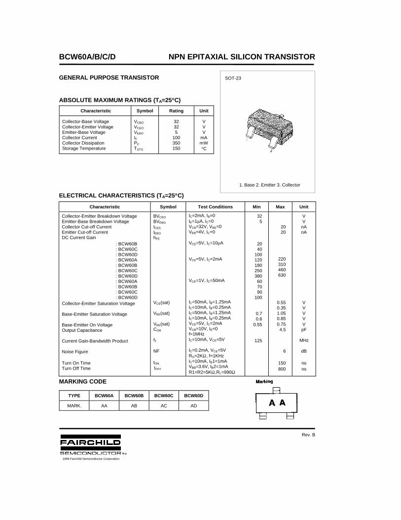
BCW60A/B/C/D NPN EPITAXIAL SILICON TRANSISTOR
GENERAL PURPOSE TRANSISTOR
ABSOLUTE MAXIMUM RATINGS (TA=25°°C)
ELECTRICAL CHARACTERISTICS (TA=25°°C)
MARKING CODE
Characteristic Symbol Rating Unit
Collector-Base VoltageCollector-Emitter VoltageEmitter-Base VoltageCollector CurrentCollector DissipationStorage Temperature
VCBO
VCEO
VEBO
ICPC
TSTG
32325
100350150
VVV
mAmW°C
Characteristic Symbol Test Conditions Min Max Unit
Collector-Emitter Breakdown VoltageEmitter-Base Breakdown VoltageCollector Cut-off CurrentEmitter Cut-off CurrentDC Current Gain
: BCW60B: BCW60C: BCW60D: BCW60A: BCW60B: BCW60C: BCW60D: BCW60A: BCW60B: BCW60C: BCW60D
Collector-Emitter Saturation Voltage
Base-Emitter Saturation Voltage
Base-Emitter On VoltageOutput Capacitance
Current Gain-Bandwidth Product
Noise Figure
Turn On TimeTurn Off Time
BVCEO
BVEBO
ICES
IEBO
hFE
VCE(sat)
VBE(sat)
VBE(sat)COB
fT
NF
tON
tOFF
IC=2mA, IB=0IE=1µA, IC=0VCB=32V, VBE=0VEB=4V, IC=0
VCE=5V, IC=10µA
VCE=5V, IC=2mA
VCE=1V, IC=50mA
IC=50mA, IB=1.25mAIC=10mA, IB=0.25mAIC=50mA, IB=1.25mAIC=10mA, IB=0.25mAVCE=5V, IC=2mAVCB=10V, IE=0f=1MHzIC=10mA, VCE=5V
IC=0.2mA, VCE=5VRG=2KΩ, f=1KHzIC=10mA, IB1=1mAVBB=3.6V, IB2=1mAR1=R2=5KΩ,RL=990Ω
325
2040
100120180250380607090
100
0.70.6
0.55
125
2020
220310460630
0.550.351.050.850.754.5
6
150800
VVnAnA
VVVVVpF
MHz
dB
nsns
TYPE BCW60A BCW60B BCW60C BCW60D
MARK. AA AB AC AD
SOT-23
1. Base 2. Emitter 3. Collector
1999 Fairchild Semiconductor Corporation
Rev. B

TRADEMARKS
ACEx™CoolFET™CROSSVOLT™E2CMOSTM
FACT™FACT Quiet Series™FAST®
FASTr™GTO™HiSeC™
The following are registered and unregistered trademarks Fairchild Semiconductor owns or is authorized to use and isnot intended to be an exhaustive list of all such trademarks.
LIFE SUPPORT POLICY
FAIRCHILD’S PRODUCTS ARE NOT AUTHORIZED FOR USE AS CRITICAL COMPONENTS IN LIFE SUPPORTDEVICES OR SYSTEMS WITHOUT THE EXPRESS WRITTEN APPROVAL OF FAIRCHILD SEMICONDUCTOR CORPORATION.As used herein:
ISOPLANAR™MICROWIRE™POP™PowerTrench™QS™Quiet Series™SuperSOT™-3SuperSOT™-6SuperSOT™-8TinyLogic™
1. Life support devices or systems are devices orsystems which, (a) are intended for surgical implant intothe body, or (b) support or sustain life, or (c) whosefailure to perform when properly used in accordancewith instructions for use provided in the labeling, can bereasonably expected to result in significant injury to theuser.
2. A critical component is any component of a lifesupport device or system whose failure to perform canbe reasonably expected to cause the failure of the lifesupport device or system, or to affect its safety oreffectiveness.
PRODUCT STATUS DEFINITIONS
Definition of Terms
Datasheet Identification Product Status Definition
Advance Information
Preliminary
No Identification Needed
Obsolete
This datasheet contains the design specifications forproduct development. Specifications may change inany manner without notice.
This datasheet contains preliminary data, andsupplementary data will be published at a later date.Fairchild Semiconductor reserves the right to makechanges at any time without notice in order to improvedesign.
This datasheet contains final specifications. FairchildSemiconductor reserves the right to make changes atany time without notice in order to improve design.
This datasheet contains specifications on a productthat has been discontinued by Fairchild semiconductor.The datasheet is printed for reference information only.
Formative orIn Design
First Production
Full Production
Not In Production
DISCLAIMER
FAIRCHILD SEMICONDUCTOR RESERVES THE RIGHT TO MAKE CHANGES WITHOUT FURTHERNOTICE TO ANY PRODUCTS HEREIN TO IMPROVE RELIABILITY, FUNCTION OR DESIGN. FAIRCHILDDOES NOT ASSUME ANY LIABILITY ARISING OUT OF THE APPLICATION OR USE OF ANY PRODUCTOR CIRCUIT DESCRIBED HEREIN; NEITHER DOES IT CONVEY ANY LICENSE UNDER ITS PATENTRIGHTS, NOR THE RIGHTS OF OTHERS.
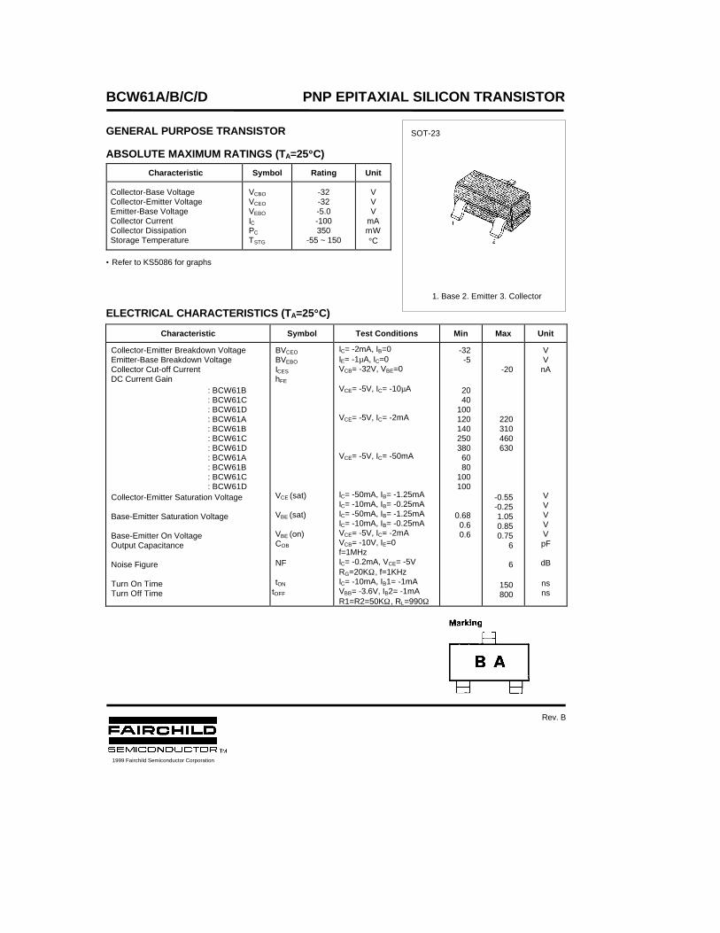
BCW61A/B/C/D PNP EPITAXIAL SILICON TRANSISTOR
GENERAL PURPOSE TRANSISTOR
ABSOLUTE MAXIMUM RATINGS (TA=25°°C)
• Refer to KS5086 for graphs
ELECTRICAL CHARACTERISTICS (TA=25°°C)
Characteristic Symbol Rating Unit
Collector-Base Voltage Collector-Emitter Voltage Emitter-Base Voltage Collector Current Collector Dissipation Storage Temperature
VCBO
VCEO
VEBO
IC PC
TSTG
-32-32-5.0-100350
-55 ~ 150
VVV
mAmW°C
Characteristic Symbol Test Conditions Min Max Unit
Collector-Emitter Breakdown VoltageEmitter-Base Breakdown VoltageCollector Cut-off CurrentDC Current Gain
: BCW61B: BCW61C: BCW61D: BCW61A: BCW61B: BCW61C: BCW61D: BCW61A: BCW61B: BCW61C: BCW61D
Collector-Emitter Saturation Voltage
Base-Emitter Saturation Voltage
Base-Emitter On VoltageOutput Capacitance
Noise Figure
Turn On TimeTurn Off Time
BVCEO
BVEBO
ICES
hFE
VCE (sat)
VBE (sat)
VBE (on)COB
NF
tON
tOFF
IC= -2mA, IB=0IE= -1µA, IC=0VCB= -32V, VBE=0
VCE= -5V, IC= -10µA
VCE= -5V, IC= -2mA
VCE= -5V, IC= -50mA
IC= -50mA, IB= -1.25mAIC= -10mA, IB= -0.25mAIC= -50mA, IB= -1.25mAIC= -10mA, IB= -0.25mAVCE= -5V, IC= -2mAVCB= -10V, IE=0f=1MHzIC= -0.2mA, VCE= -5VRG=20KΩ, f=1KHzIC= -10mA, IB1= -1mAVBB= -3.6V, IB2= -1mAR1=R2=50KΩ, RL=990Ω
-32-5
2040
1001201402503806080
100100
0.680.60.6
-20
220310460630
-0.55-0.251.050.850.75
6
6
150800
VVnA
VVVVVpF
dB
nsns
SOT-23
1. Base 2. Emitter 3. Collector
1999 Fairchild Semiconductor Corporation
Rev. B
BCW61A/B/C/D PNP EPITAXIAL SILICON TRANSISTOR
MARKING CODE
TYPE BCW61A BCW61B BCW61C BCW61D
MARK. BA BB BC BD

TRADEMARKS
ACEx™CoolFET™CROSSVOLT™E2CMOSTM
FACT™FACT Quiet Series™FAST®
FASTr™GTO™HiSeC™
The following are registered and unregistered trademarks Fairchild Semiconductor owns or is authorized to use and isnot intended to be an exhaustive list of all such trademarks.
LIFE SUPPORT POLICY
FAIRCHILD’S PRODUCTS ARE NOT AUTHORIZED FOR USE AS CRITICAL COMPONENTS IN LIFE SUPPORTDEVICES OR SYSTEMS WITHOUT THE EXPRESS WRITTEN APPROVAL OF FAIRCHILD SEMICONDUCTOR CORPORATION.As used herein:
ISOPLANAR™MICROWIRE™POP™PowerTrench™QS™Quiet Series™SuperSOT™-3SuperSOT™-6SuperSOT™-8TinyLogic™
1. Life support devices or systems are devices orsystems which, (a) are intended for surgical implant intothe body, or (b) support or sustain life, or (c) whosefailure to perform when properly used in accordancewith instructions for use provided in the labeling, can bereasonably expected to result in significant injury to theuser.
2. A critical component is any component of a lifesupport device or system whose failure to perform canbe reasonably expected to cause the failure of the lifesupport device or system, or to affect its safety oreffectiveness.
PRODUCT STATUS DEFINITIONS
Definition of Terms
Datasheet Identification Product Status Definition
Advance Information
Preliminary
No Identification Needed
Obsolete
This datasheet contains the design specifications forproduct development. Specifications may change inany manner without notice.
This datasheet contains preliminary data, andsupplementary data will be published at a later date.Fairchild Semiconductor reserves the right to makechanges at any time without notice in order to improvedesign.
This datasheet contains final specifications. FairchildSemiconductor reserves the right to make changes atany time without notice in order to improve design.
This datasheet contains specifications on a productthat has been discontinued by Fairchild semiconductor.The datasheet is printed for reference information only.
Formative orIn Design
First Production
Full Production
Not In Production
DISCLAIMER
FAIRCHILD SEMICONDUCTOR RESERVES THE RIGHT TO MAKE CHANGES WITHOUT FURTHERNOTICE TO ANY PRODUCTS HEREIN TO IMPROVE RELIABILITY, FUNCTION OR DESIGN. FAIRCHILDDOES NOT ASSUME ANY LIABILITY ARISING OUT OF THE APPLICATION OR USE OF ANY PRODUCTOR CIRCUIT DESCRIBED HEREIN; NEITHER DOES IT CONVEY ANY LICENSE UNDER ITS PATENTRIGHTS, NOR THE RIGHTS OF OTHERS.
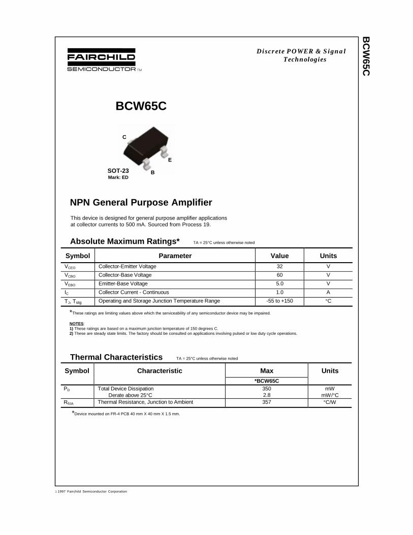
BC
W65C
BCW65C
NPN General Purpose Amplifier
This device is designed for general purpose amplifier applicationsat collector currents to 500 mA. Sourced from Process 19.
C
E
BSOT-23Mark: ED
Absolute Maximum Ratings* TA = 25°C unless otherwise noted
*These ratings are limiting values above which the serviceability of any semiconductor device may be impaired.
NOTES:1) These ratings are based on a maximum junction temperature of 150 degrees C.2) These are steady state limits. The factory should be consulted on applications involving pulsed or low duty cycle operations.
Thermal Characteristics TA = 25°C unless otherwise noted
Symbol Parameter Value UnitsVCEO Collector-Emitter Voltage 32 V
VCBO Collector-Base Voltage 60 V
VEBO Emitter-Base Voltage 5.0 V
IC Collector Current - Continuous 1.0 A
TJ, Tstg Operating and Storage Junction Temperature Range -55 to +150 °C
Symbol Characteristic Max Units*BCW65C
PD Total Device DissipationDerate above 25°C
3502.8
mWmW/°C
RθJA Thermal Resistance, Junction to Ambient 357 °C/W
*Device mounted on FR-4 PCB 40 mm X 40 mm X 1.5 mm.
Discrete POWER & SignalTechnologies
ã 1997 Fairchild Semiconductor Corporation

BC
W65C
OFF CHARACTERISTICSV(BR)CEO Collector-Emitter Breakdown Voltage IC = 10 mA, IB = 0 32 V
V(BR)CBO Collector-Base Breakdown Voltage IC = 10 µA, IE = 0 60 V
V(BR)EBO Emitter-Base Breakdown Voltage IE = 10 µA, IC = 0 5.0 V
ICES Collector-Cutoff Current VCB = 32 V, IE = 0VCB = 32 V, IE = 0, TA = 150°C
2020
nAµA
IEBO Emitter-Cutoff Current VEB = 4.0 V, IC = 0 20 nA
Electrical Characteristics TA = 25°C unless otherwise noted
Symbol Parameter Test C onditions Min Max Units
ON CHARACTERISTICShFE DC Current Gain IC = 100 µA, VCE = 10 V
IC = 10 mA, VCE = 1.0 VIC = 100 mA, VCE = 1.0 VIC = 500 mA, VCE = 2.0 V
8018025050
630
VCE(sat) Collector-Emitter Saturation Voltage IC = 100 mA, IB = 10 mAIC = 500 mA, B = 50 mA
0.30.7
V
VBE(sat) Base-Emitter Saturation Voltage IC = 500 mA, IB = 50 mA 2.0 V
SMALL SIGNAL CHARACTERISTICSfT Current Gain - Bandwidth Product IC = 20 mA, VCE = 10 V,
f = 100 MHz100 MHz
Cobo Output Capacitance VCB = 10 V, IE = 0, f = 1.0 MHz 12 pF
Cibo Input Capacitance VEB = 0.5 V, IC = 0, f = 1.0 MHz 80 pF
NF Noise Figure IC = 0.2 mA, VCE = 5.0,RS = 1.0 kΩ, f = 1.0 kHz,BW = 200 Hz
10 dB
NPN General Purpose Amplifier(continued)
Typical Characteristics
Collector-Emitter SaturationVoltage vs Collector Current
1 10 100 500
0.1
0.2
0.3
0.4
I - COLLECTOR CURRENT (mA)V
-
CO
LLE
CT
OR
-EM
ITT
ER
VO
LTA
GE
(V
)C
ES
AT
25 °C
C
β = 10
125 °C
- 40 °C
Typical Pulsed Current Gainvs Collector Current
0.1 0.3 1 3 10 30 100 3000
100
200
300
400
500
I - COLLECTOR CURRENT (mA)h
- T
YP
ICA
L P
ULS
ED
CU
RR
EN
T G
AIN
C
FE
125 °C
25 °C
- 40 °C
V = 5VCE
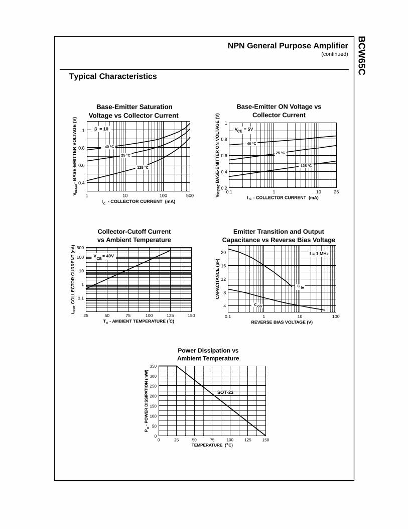
BC
W65C
NPN General Purpose Amplifier(continued)
Typical Characteristics
Base-Emitter ON Voltage vsCollector Current
0.1 1 10 250.2
0.4
0.6
0.8
1
I - COLLECTOR CURRENT (mA)V
-
BA
SE
-EM
ITT
ER
ON
VO
LTA
GE
(V
)B
E(O
N)
C
V = 5VCE
25 °C
125 °C
- 40 °C
Base-Emitter SaturationVoltage vs Collector Current
1 10 100 500
0.4
0.6
0.8
1
I - COLLECTOR CURRENT (mA)
V
-
BA
SE
-EM
ITT
ER
VO
LTA
GE
(V
)B
ES
AT
C
β = 10
25 °C
125 °C
- 40 °C
Collector-Cutoff Currentvs Ambient Temperature
25 50 75 100 125 150
0.1
1
10
100
500
T - AMBIENT TEMPERATURE ( C)
I
- C
OLL
EC
TOR
CU
RR
EN
T (
nA)
A
V = 40VCB
CB
O
°
Emitter Transition and OutputCapacitance vs Reverse Bias Voltage
0.1 1 10 100
4
8
12
16
20
REVERSE BIAS VOLTAGE (V)
CA
PA
CIT
AN
CE
(pF
)
f = 1 MHz
C ob
C te
Power Dissipation vsAmbient Temperature
0 25 50 75 100 125 1500
50
100
150
200
250
300
350
TEMPERATURE ( C)
P
- P
OW
ER
DIS
SIP
ATIO
N (
mW
)D
o
SOT-23

TRADEMARKS
ACEx™CoolFET™CROSSVOLT™E2CMOSTM
FACT™FACT Quiet Series™FAST®
FASTr™GTO™HiSeC™
The following are registered and unregistered trademarks Fairchild Semiconductor owns or is authorized to use and isnot intended to be an exhaustive list of all such trademarks.
LIFE SUPPORT POLICY
FAIRCHILD’S PRODUCTS ARE NOT AUTHORIZED FOR USE AS CRITICAL COMPONENTS IN LIFE SUPPORTDEVICES OR SYSTEMS WITHOUT THE EXPRESS WRITTEN APPROVAL OF FAIRCHILD SEMICONDUCTOR CORPORATION.As used herein:
ISOPLANAR™MICROWIRE™POP™PowerTrench™QS™Quiet Series™SuperSOT™-3SuperSOT™-6SuperSOT™-8TinyLogic™
1. Life support devices or systems are devices orsystems which, (a) are intended for surgical implant intothe body, or (b) support or sustain life, or (c) whosefailure to perform when properly used in accordancewith instructions for use provided in the labeling, can bereasonably expected to result in significant injury to theuser.
2. A critical component is any component of a lifesupport device or system whose failure to perform canbe reasonably expected to cause the failure of the lifesupport device or system, or to affect its safety oreffectiveness.
PRODUCT STATUS DEFINITIONS
Definition of Terms
Datasheet Identification Product Status Definition
Advance Information
Preliminary
No Identification Needed
Obsolete
This datasheet contains the design specifications forproduct development. Specifications may change inany manner without notice.
This datasheet contains preliminary data, andsupplementary data will be published at a later date.Fairchild Semiconductor reserves the right to makechanges at any time without notice in order to improvedesign.
This datasheet contains final specifications. FairchildSemiconductor reserves the right to make changes atany time without notice in order to improve design.
This datasheet contains specifications on a productthat has been discontinued by Fairchild semiconductor.The datasheet is printed for reference information only.
Formative orIn Design
First Production
Full Production
Not In Production
DISCLAIMER
FAIRCHILD SEMICONDUCTOR RESERVES THE RIGHT TO MAKE CHANGES WITHOUT FURTHERNOTICE TO ANY PRODUCTS HEREIN TO IMPROVE RELIABILITY, FUNCTION OR DESIGN. FAIRCHILDDOES NOT ASSUME ANY LIABILITY ARISING OUT OF THE APPLICATION OR USE OF ANY PRODUCTOR CIRCUIT DESCRIBED HEREIN; NEITHER DOES IT CONVEY ANY LICENSE UNDER ITS PATENTRIGHTS, NOR THE RIGHTS OF OTHERS.
BC
W68G
BCW68G
PNP General Purpose Amplifier
This device is designed for general purpose amplifier and switchingapplications at currents to 500 mA. Sourced from Process 63.
Symbol Characteristic Max Units*BCW68C
PD Total Device DissipationDerate above 25°C
3502.8
mWmW/°C
RθJA Thermal Resistance, Junction to Ambient 357 °C/W
C
E
BSOT-23Mark: DG
Absolute Maximum Ratings* TA = 25°C unless otherwise noted
*These ratings are limiting values above which the serviceability of any semiconductor device may be impaired.
NOTES:1) These ratings are based on a maximum junction temperature of 150 degrees C.2) These are steady state limits. The factory should be consulted on applications involving pulsed or low duty cycle operations.
Thermal Characteristics TA = 25°C unless otherwise noted
Symbol Parameter Value UnitsVCEO Collector-Emitter Voltage 45 V
VCBO Collector-Base Voltage 60 V
VEBO Emitter-Base Voltage 5.0 V
IC Collector Current - Continuous 800 mA
TJ, Tstg Operating and Storage Junction Temperature Range -55 to +150 °C
*Device mounted on FR-4 PCB 40 mm X 40 mm X 1.5 mm.
Discrete POWER & SignalTechnologies
ã 1997 Fairchild Semiconductor Corporation
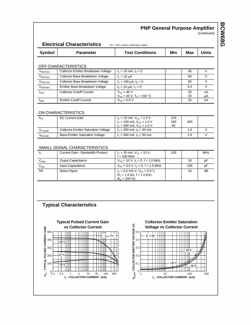
BC
W68G
Electrical Characteristics TA = 25°C unless otherwise noted
OFF CHARACTERISTICSV(BR)CEO Collector-Emitter Breakdown Voltage IC = 10 mA, IB = 0 45 V
V(BR)CES Collector-Base Breakdown Voltage IC = 10 µA 60 V
V(BR)CBO Collector-Base Breakdown Voltage IC = 100 µA, IE = 0 60 V
V(BR)EBO Emitter-Base Breakdown Voltage IE = 10 µA, IC = 0 5.0 V
ICES Collector-Cutoff Current VCE = 45 VVCE = 45 V, TA = 150 °C
2010
nAµA
IEBO Emitter-Cutoff Current VEB = 4.0 V 20 nA
ON CHARACTERISTICShFE DC Current Gain IC = 10 mA, VCE = 1.0 V
IC = 100 mA, VCE = 1.0 VIC = 300 mA, VCE = 1.0 V
12016060
400
VCE(sat) Collector-Emitter Saturation Voltage IC = 300 mA, IB = 30 mA 1.5 V
VBE(sat) Base-Emitter Saturation Voltage IC = 500 mA, IB = 50 mA 2.0 V
SMALL SIGNAL CHARACTERISTICSfT Current Gain - Bandwidth Product IC = 20 mA, VCE = 10 V,
f = 100 MHz100 MHz
Cobo Ouput Capacitance VCB = 10 V, IE = 0, f = 1.0 MHz 18 pF
Cibo Input Capacitance VEB = 0.5 V, IE = 0, f = 1.0 MHz 105 pF
NF Noise Figure IC = 0.2 mA V, VCE = 5.0 V,RS = 1.0 kΩ, f = 1.0 kHz,BW = 200 Hz
10 dB
PNP General Purpose Amplifier(continued)
Symbol Parameter Test C onditions Min Max Units
Typical Characteristics
Typical Pulsed Current Gainvs Collector Current
0.1 0.3 1 3 10 30 100 3000
100
200
300
400
500
I - COLLECTOR CURRENT (mA)
h
- T
YP
ICA
L P
ULS
ED
CU
RR
EN
T G
AIN
C
FE
125 °C
25 °C
- 40 °C
V = 5VCE
Collector-Emitter SaturationVoltage vs Collector Current
1 10 100 5000
0.1
0.2
0.3
0.4
0.5
I - COLLECTOR CURRENT (mA)V
-
CO
LLE
CTO
R E
MIT
TE
R V
OLT
AG
E (
V)
CCE
SAT
β = 10
25 °C
- 40 ºC125 ºC
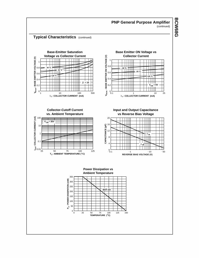
BC
W68G
PNP General Purpose Amplifier(continued)
Typical Characteristics (continued)
Base-Emitter SaturationVoltage vs Collector Current
1 10 100 5000
0.2
0.4
0.6
0.8
1
I - COLLECTOR CURRENT (mA)
V
-
BA
SE
EM
ITT
ER
VO
LTA
GE
(V
)
C
BE
SAT
25 °C- 40 ºC
125 ºC
β = 10
Base Emitter ON Voltage vsCollector Current
0.1 1 10 250
0.2
0.4
0.6
0.8
1
I - COLLECTOR CURRENT (mA)V
-
BA
SE
EM
ITT
ER
ON
VO
LTA
GE
(V
)
C
BE
ON
V = 5VCE
25 °C
- 40 ºC
125 ºC
Collector-Cutoff Currentvs. Ambient Temperature
25 50 75 100 1250.01
0.1
1
10
100
T - AMBIENT TEMPERATURE ( C)
I
- C
OLL
EC
TOR
CU
RR
EN
T (
nA)
A
CB
O
º
V = 35VCB
Input and Output Capacitancevs Reverse Bias Voltage
0.1 1 10 500
4
8
12
16
20
REVERSE BIAS VOLTAGE (V)
CA
PA
CIT
AN
CE
(pF
)
C ob
C ib
Power Dissipation vsAmbient Temperature
0 25 50 75 100 125 1500
50
100
150
200
250
300
350
TEMPERATURE ( C)
P
- P
OW
ER
DIS
SIP
ATIO
N (
mW
)D
o
SOT-23

TRADEMARKS
ACEx™CoolFET™CROSSVOLT™E2CMOSTM
FACT™FACT Quiet Series™FAST®
FASTr™GTO™HiSeC™
The following are registered and unregistered trademarks Fairchild Semiconductor owns or is authorized to use and isnot intended to be an exhaustive list of all such trademarks.
LIFE SUPPORT POLICY
FAIRCHILD’S PRODUCTS ARE NOT AUTHORIZED FOR USE AS CRITICAL COMPONENTS IN LIFE SUPPORTDEVICES OR SYSTEMS WITHOUT THE EXPRESS WRITTEN APPROVAL OF FAIRCHILD SEMICONDUCTOR CORPORATION.As used herein:
ISOPLANAR™MICROWIRE™POP™PowerTrench™QS™Quiet Series™SuperSOT™-3SuperSOT™-6SuperSOT™-8TinyLogic™
1. Life support devices or systems are devices orsystems which, (a) are intended for surgical implant intothe body, or (b) support or sustain life, or (c) whosefailure to perform when properly used in accordancewith instructions for use provided in the labeling, can bereasonably expected to result in significant injury to theuser.
2. A critical component is any component of a lifesupport device or system whose failure to perform canbe reasonably expected to cause the failure of the lifesupport device or system, or to affect its safety oreffectiveness.
PRODUCT STATUS DEFINITIONS
Definition of Terms
Datasheet Identification Product Status Definition
Advance Information
Preliminary
No Identification Needed
Obsolete
This datasheet contains the design specifications forproduct development. Specifications may change inany manner without notice.
This datasheet contains preliminary data, andsupplementary data will be published at a later date.Fairchild Semiconductor reserves the right to makechanges at any time without notice in order to improvedesign.
This datasheet contains final specifications. FairchildSemiconductor reserves the right to make changes atany time without notice in order to improve design.
This datasheet contains specifications on a productthat has been discontinued by Fairchild semiconductor.The datasheet is printed for reference information only.
Formative orIn Design
First Production
Full Production
Not In Production
DISCLAIMER
FAIRCHILD SEMICONDUCTOR RESERVES THE RIGHT TO MAKE CHANGES WITHOUT FURTHERNOTICE TO ANY PRODUCTS HEREIN TO IMPROVE RELIABILITY, FUNCTION OR DESIGN. FAIRCHILDDOES NOT ASSUME ANY LIABILITY ARISING OUT OF THE APPLICATION OR USE OF ANY PRODUCTOR CIRCUIT DESCRIBED HEREIN; NEITHER DOES IT CONVEY ANY LICENSE UNDER ITS PATENTRIGHTS, NOR THE RIGHTS OF OTHERS.
BCW71 NPN EPITAXIAL SILICON TRANSISTOR
GENERAL PURPOSE TRANSISTOR
ABSOLUTE MAXIMUM RATINGS (TA=25°°C)
• Refer to KST2222 for graphs
ELECTRICAL CHARACTERISTICS (TA=25°°C)
Characteristic Symbol Rating Unit
Collector-Base VoltageCollector-Emitter VoltageEmitter-Base VoltageCollector CurrentCollector DissipationStorage Temperature
VCBO
VCEO
VEBO
ICPC
TSTG
50455
100350150
VVV
mAmW°C
Characteristic Symbol Test Conditions Min Typ Max Unit
Collector-Base Breakdown VoltageCollector-Emitter Breakdown VoltageCollector-Emitter Breakdown VoltageEmitter-Base Breakdown VoltageCollector Cut-off CurrentDC Current Gain
Collector-Emitter Saturation Voltage
Base-Emitter Saturation VoltageBase-Emitter On Voltage
Current Gain Bandwidth Product
Output Capacitance
Noise Figures
BVCBO
BVCEO
BVCES
BVEBO
ICBO
hFE
VCE (sat)
VBE (sat)VBE (on)
fT
COB
NF
IC=10µA, IE=0IC=2mA, IB=0IC=2mA, VEB=0IE=10µA, IC=0VCB=20V, IE=0VCE=5V, IC=2mAIC=10mA, IB=0.5mAIC=50mA, IB=2.5mAIC=50mA, IB=2.5mAIC=2mA, VCE=5VVCE=5V, IC=10mAf=35MHzVCB=10V, IE=0f=1MHzVCE=5V, IC=2.0mARG=2KΩ, f=1KHz
5045455
110
0.6
0.210.85
300
100220
0.25
0.75
410
VVVVnA
VVVV
MHz
pF
dB
SOT-23
1. Base 2. Emitter 3. Collector
1999 Fairchild Semiconductor Corporation
Rev. B

TRADEMARKS
ACEx™CoolFET™CROSSVOLT™E2CMOSTM
FACT™FACT Quiet Series™FAST®
FASTr™GTO™HiSeC™
The following are registered and unregistered trademarks Fairchild Semiconductor owns or is authorized to use and isnot intended to be an exhaustive list of all such trademarks.
LIFE SUPPORT POLICY
FAIRCHILD’S PRODUCTS ARE NOT AUTHORIZED FOR USE AS CRITICAL COMPONENTS IN LIFE SUPPORTDEVICES OR SYSTEMS WITHOUT THE EXPRESS WRITTEN APPROVAL OF FAIRCHILD SEMICONDUCTOR CORPORATION.As used herein:
ISOPLANAR™MICROWIRE™POP™PowerTrench™QS™Quiet Series™SuperSOT™-3SuperSOT™-6SuperSOT™-8TinyLogic™
1. Life support devices or systems are devices orsystems which, (a) are intended for surgical implant intothe body, or (b) support or sustain life, or (c) whosefailure to perform when properly used in accordancewith instructions for use provided in the labeling, can bereasonably expected to result in significant injury to theuser.
2. A critical component is any component of a lifesupport device or system whose failure to perform canbe reasonably expected to cause the failure of the lifesupport device or system, or to affect its safety oreffectiveness.
PRODUCT STATUS DEFINITIONS
Definition of Terms
Datasheet Identification Product Status Definition
Advance Information
Preliminary
No Identification Needed
Obsolete
This datasheet contains the design specifications forproduct development. Specifications may change inany manner without notice.
This datasheet contains preliminary data, andsupplementary data will be published at a later date.Fairchild Semiconductor reserves the right to makechanges at any time without notice in order to improvedesign.
This datasheet contains final specifications. FairchildSemiconductor reserves the right to make changes atany time without notice in order to improve design.
This datasheet contains specifications on a productthat has been discontinued by Fairchild semiconductor.The datasheet is printed for reference information only.
Formative orIn Design
First Production
Full Production
Not In Production
DISCLAIMER
FAIRCHILD SEMICONDUCTOR RESERVES THE RIGHT TO MAKE CHANGES WITHOUT FURTHERNOTICE TO ANY PRODUCTS HEREIN TO IMPROVE RELIABILITY, FUNCTION OR DESIGN. FAIRCHILDDOES NOT ASSUME ANY LIABILITY ARISING OUT OF THE APPLICATION OR USE OF ANY PRODUCTOR CIRCUIT DESCRIBED HEREIN; NEITHER DOES IT CONVEY ANY LICENSE UNDER ITS PATENTRIGHTS, NOR THE RIGHTS OF OTHERS.
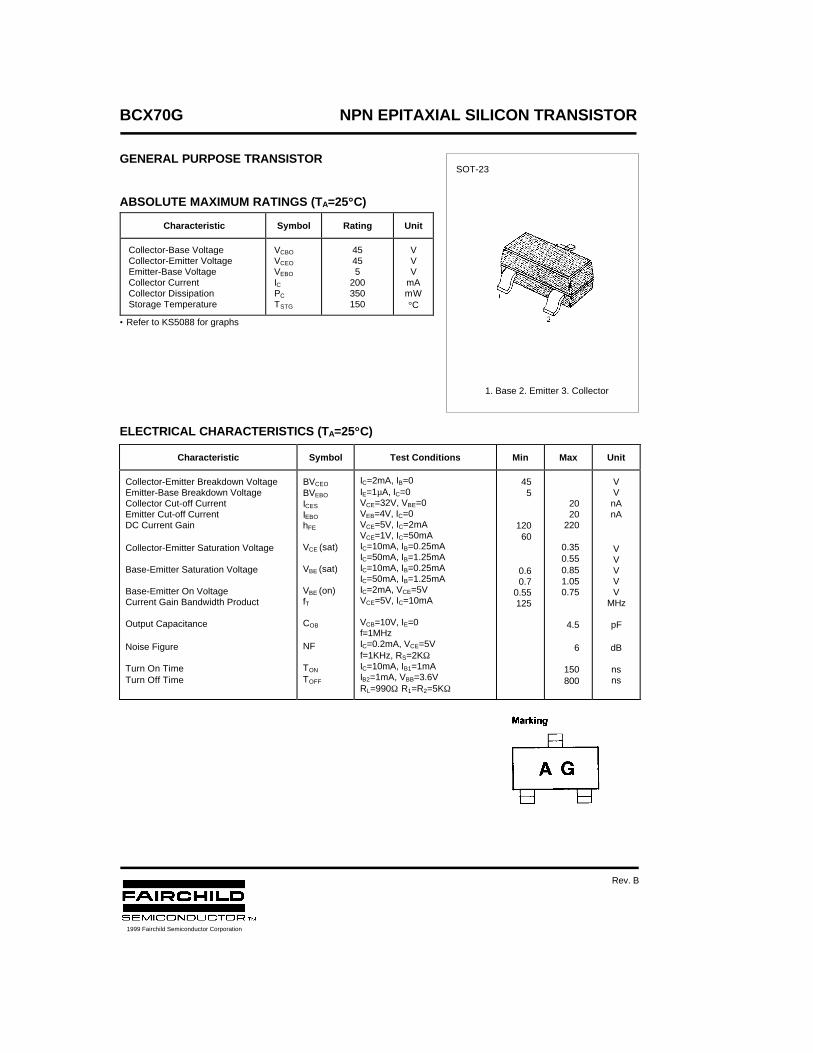
BCX70G NPN EPITAXIAL SILICON TRANSISTOR
GENERAL PURPOSE TRANSISTOR
ABSOLUTE MAXIMUM RATINGS (TA=25°°C)
• Refer to KS5088 for graphs
ELECTRICAL CHARACTERISTICS (TA=25°°C)
Characteristic Symbol Rating Unit
Collector-Base Voltage Collector-Emitter Voltage Emitter-Base Voltage Collector Current Collector Dissipation Storage Temperature
VCBO
VCEO
VEBO
IC PC
TSTG
45455
200350150
VVV
mAmW°C
Characteristic Symbol Test Conditions Min Max Unit
Collector-Emitter Breakdown VoltageEmitter-Base Breakdown VoltageCollector Cut-off CurrentEmitter Cut-off CurrentDC Current Gain
Collector-Emitter Saturation Voltage
Base-Emitter Saturation Voltage
Base-Emitter On VoltageCurrent Gain Bandwidth Product
Output Capacitance
Noise Figure
Turn On TimeTurn Off Time
BVCEO
BVEBO
ICES
IEBO
hFE
VCE (sat)
VBE (sat)
VBE (on)fT
COB
NF
TON
TOFF
IC=2mA, IB=0IE=1µA, IC=0VCE=32V, VBE=0VEB=4V, IC=0VCE=5V, IC=2mAVCE=1V, IC=50mAIC=10mA, IB=0.25mAIC=50mA, IB=1.25mAIC=10mA, IB=0.25mAIC=50mA, IB=1.25mAIC=2mA, VCE=5VVCE=5V, IC=10mA
VCB=10V, IE=0f=1MHzIC=0.2mA, VCE=5Vf=1KHz, RS=2KΩIC=10mA, IB1=1mAIB2=1mA, VBB=3.6VRL=990Ω R1=R2=5KΩ
455
12060
0.60.7
0.55125
2020
220
0.350.550.851.050.75
4.5
6
150800
VVnAnA
VVVVV
MHz
pF
dB
nsns
SOT-23
1. Base 2. Emitter 3. Collector
1999 Fairchild Semiconductor Corporation
Rev. B

TRADEMARKS
ACEx™CoolFET™CROSSVOLT™E2CMOSTM
FACT™FACT Quiet Series™FAST®
FASTr™GTO™HiSeC™
The following are registered and unregistered trademarks Fairchild Semiconductor owns or is authorized to use and isnot intended to be an exhaustive list of all such trademarks.
LIFE SUPPORT POLICY
FAIRCHILD’S PRODUCTS ARE NOT AUTHORIZED FOR USE AS CRITICAL COMPONENTS IN LIFE SUPPORTDEVICES OR SYSTEMS WITHOUT THE EXPRESS WRITTEN APPROVAL OF FAIRCHILD SEMICONDUCTOR CORPORATION.As used herein:
ISOPLANAR™MICROWIRE™POP™PowerTrench™QS™Quiet Series™SuperSOT™-3SuperSOT™-6SuperSOT™-8TinyLogic™
1. Life support devices or systems are devices orsystems which, (a) are intended for surgical implant intothe body, or (b) support or sustain life, or (c) whosefailure to perform when properly used in accordancewith instructions for use provided in the labeling, can bereasonably expected to result in significant injury to theuser.
2. A critical component is any component of a lifesupport device or system whose failure to perform canbe reasonably expected to cause the failure of the lifesupport device or system, or to affect its safety oreffectiveness.
PRODUCT STATUS DEFINITIONS
Definition of Terms
Datasheet Identification Product Status Definition
Advance Information
Preliminary
No Identification Needed
Obsolete
This datasheet contains the design specifications forproduct development. Specifications may change inany manner without notice.
This datasheet contains preliminary data, andsupplementary data will be published at a later date.Fairchild Semiconductor reserves the right to makechanges at any time without notice in order to improvedesign.
This datasheet contains final specifications. FairchildSemiconductor reserves the right to make changes atany time without notice in order to improve design.
This datasheet contains specifications on a productthat has been discontinued by Fairchild semiconductor.The datasheet is printed for reference information only.
Formative orIn Design
First Production
Full Production
Not In Production
DISCLAIMER
FAIRCHILD SEMICONDUCTOR RESERVES THE RIGHT TO MAKE CHANGES WITHOUT FURTHERNOTICE TO ANY PRODUCTS HEREIN TO IMPROVE RELIABILITY, FUNCTION OR DESIGN. FAIRCHILDDOES NOT ASSUME ANY LIABILITY ARISING OUT OF THE APPLICATION OR USE OF ANY PRODUCTOR CIRCUIT DESCRIBED HEREIN; NEITHER DOES IT CONVEY ANY LICENSE UNDER ITS PATENTRIGHTS, NOR THE RIGHTS OF OTHERS.
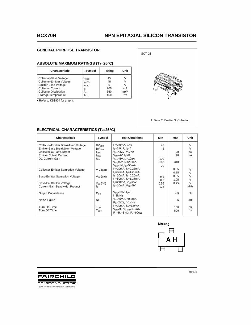
BCX70H NPN EPITAXIAL SILICON TRANSISTOR
GENERAL PURPOSE TRANSISTOR
ABSOLUTE MAXIMUM RATINGS (TA=25°°C)
• Refer to KS3904 for graphs
ELECTRICAL CHARACTERISTICS (TA=25°°C)
Characteristic Symbol Rating Unit
Collector-Base Voltage Collector-Emitter Voltage Emitter-Base Voltage Collector Current Collector Dissipation Storage Temperature
VCBO
VCEO
VEBO
IC PC
TSTG
45455
200350150
VVV
mAmW°C
Characteristic Symbol Test Conditions Min Max Unit
Collector-Emitter Breakdown VoltageEmitter-Base Breakdown VoltageCollector Cut-off CurrentEmitter Cut-off CurrentDC Current Gain
Collector-Emitter Saturation Voltage
Base-Emitter Saturation Voltage
Base-Emitter On VoltageCurrent Gain Bandwidth Product
Output Capacitance
Noise Figure
Turn On TimeTurn Off Time
BVCEO
BVEBO
ICES
IEBO
hFE
VCE (sat)
VBE (sat)
VBE (on)fT
COB
NF
TON
TOFF
IC=2.0mA, IB=0IE=1.0µA, IC=0VCE=32V, VBE=0VEB=4V, IC=0VCE=5V, IC=10µAVCE=5V, IC=2.0mAVCE=1V, IC=50mAIC=10mA, IB=0.25mAIC=50mA, IB=1.25mAIC=10mA, IB=0.25mAIC=50mA, IB=1.25mAIC=2.0mA, VCE=5VIC=10mA, VCE=5V
VCE=10V, IE=0f=1MHzVCE=5V, IC=0.2mARS=2KΩ, f=1KHzIC=10mA, IB1=1.0mAVBB=3.6V, IB2=1.0mAR1=R2=5KΩ, RL=990Ω
455
12018070
0.60.7
0.55125
2020
310
0.350.550.851.050.75
4.5
6
150800
VVnAnA
VVVVV
MHz
pF
dB
nsns
SOT-23
1. Base 2. Emitter 3. Collector
1999 Fairchild Semiconductor Corporation
Rev. B
TRADEMARKS
ACEx™CoolFET™CROSSVOLT™E2CMOSTM
FACT™FACT Quiet Series™FAST®
FASTr™GTO™HiSeC™
The following are registered and unregistered trademarks Fairchild Semiconductor owns or is authorized to use and isnot intended to be an exhaustive list of all such trademarks.
LIFE SUPPORT POLICY
FAIRCHILD’S PRODUCTS ARE NOT AUTHORIZED FOR USE AS CRITICAL COMPONENTS IN LIFE SUPPORTDEVICES OR SYSTEMS WITHOUT THE EXPRESS WRITTEN APPROVAL OF FAIRCHILD SEMICONDUCTOR CORPORATION.As used herein:
ISOPLANAR™MICROWIRE™POP™PowerTrench™QS™Quiet Series™SuperSOT™-3SuperSOT™-6SuperSOT™-8TinyLogic™
1. Life support devices or systems are devices orsystems which, (a) are intended for surgical implant intothe body, or (b) support or sustain life, or (c) whosefailure to perform when properly used in accordancewith instructions for use provided in the labeling, can bereasonably expected to result in significant injury to theuser.
2. A critical component is any component of a lifesupport device or system whose failure to perform canbe reasonably expected to cause the failure of the lifesupport device or system, or to affect its safety oreffectiveness.
PRODUCT STATUS DEFINITIONS
Definition of Terms
Datasheet Identification Product Status Definition
Advance Information
Preliminary
No Identification Needed
Obsolete
This datasheet contains the design specifications forproduct development. Specifications may change inany manner without notice.
This datasheet contains preliminary data, andsupplementary data will be published at a later date.Fairchild Semiconductor reserves the right to makechanges at any time without notice in order to improvedesign.
This datasheet contains final specifications. FairchildSemiconductor reserves the right to make changes atany time without notice in order to improve design.
This datasheet contains specifications on a productthat has been discontinued by Fairchild semiconductor.The datasheet is printed for reference information only.
Formative orIn Design
First Production
Full Production
Not In Production
DISCLAIMER
FAIRCHILD SEMICONDUCTOR RESERVES THE RIGHT TO MAKE CHANGES WITHOUT FURTHERNOTICE TO ANY PRODUCTS HEREIN TO IMPROVE RELIABILITY, FUNCTION OR DESIGN. FAIRCHILDDOES NOT ASSUME ANY LIABILITY ARISING OUT OF THE APPLICATION OR USE OF ANY PRODUCTOR CIRCUIT DESCRIBED HEREIN; NEITHER DOES IT CONVEY ANY LICENSE UNDER ITS PATENTRIGHTS, NOR THE RIGHTS OF OTHERS.
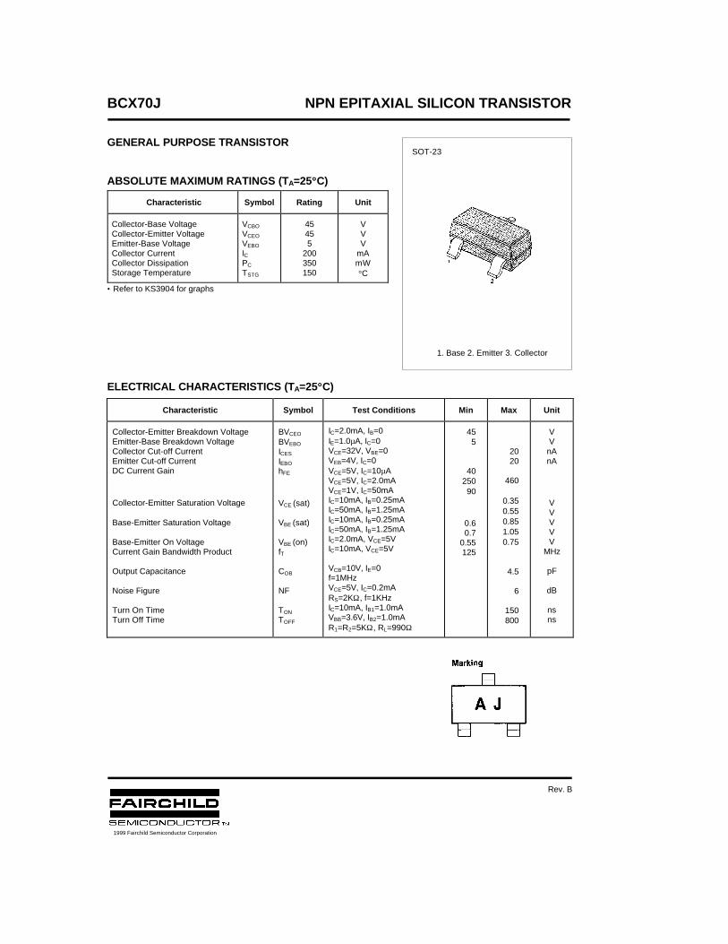
BCX70J NPN EPITAXIAL SILICON TRANSISTOR
GENERAL PURPOSE TRANSISTOR
ABSOLUTE MAXIMUM RATINGS (TA=25°°C)
• Refer to KS3904 for graphs
ELECTRICAL CHARACTERISTICS (TA=25°°C)
Characteristic Symbol Rating Unit
Collector-Base Voltage Collector-Emitter Voltage Emitter-Base Voltage Collector Current Collector Dissipation Storage Temperature
VCBO
VCEO
VEBO
IC PC
TSTG
45455
200350150
VVV
mAmW°C
Characteristic Symbol Test Conditions Min Max Unit
Collector-Emitter Breakdown VoltageEmitter-Base Breakdown VoltageCollector Cut-off CurrentEmitter Cut-off CurrentDC Current Gain
Collector-Emitter Saturation Voltage
Base-Emitter Saturation Voltage
Base-Emitter On VoltageCurrent Gain Bandwidth Product
Output Capacitance
Noise Figure
Turn On TimeTurn Off Time
BVCEO
BVEBO
ICES
IEBO
hFE
VCE (sat)
VBE (sat)
VBE (on)fT
COB
NF
TON
TOFF
IC=2.0mA, IB=0IE=1.0µA, IC=0VCE=32V, VBE=0VEB=4V, IC=0VCE=5V, IC=10µAVCE=5V, IC=2.0mAVCE=1V, IC=50mAIC=10mA, IB=0.25mAIC=50mA, IB=1.25mAIC=10mA, IB=0.25mAIC=50mA, IB=1.25mAIC=2.0mA, VCE=5VIC=10mA, VCE=5V
VCB=10V, IE=0f=1MHzVCE=5V, IC=0.2mARS=2KΩ, f=1KHzIC=10mA, IB1=1.0mAVBB=3.6V, IB2=1.0mAR1=R2=5KΩ, RL=990Ω
455
4025090
0.60.7
0.55125
2020
460
0.350.550.851.050.75
4.5
6
150800
VVnAnA
VVVVV
MHz
pF
dB
nsns
SOT-23
1. Base 2. Emitter 3. Collector
1999 Fairchild Semiconductor Corporation
Rev. B

TRADEMARKS
ACEx™CoolFET™CROSSVOLT™E2CMOSTM
FACT™FACT Quiet Series™FAST®
FASTr™GTO™HiSeC™
The following are registered and unregistered trademarks Fairchild Semiconductor owns or is authorized to use and isnot intended to be an exhaustive list of all such trademarks.
LIFE SUPPORT POLICY
FAIRCHILD’S PRODUCTS ARE NOT AUTHORIZED FOR USE AS CRITICAL COMPONENTS IN LIFE SUPPORTDEVICES OR SYSTEMS WITHOUT THE EXPRESS WRITTEN APPROVAL OF FAIRCHILD SEMICONDUCTOR CORPORATION.As used herein:
ISOPLANAR™MICROWIRE™POP™PowerTrench™QS™Quiet Series™SuperSOT™-3SuperSOT™-6SuperSOT™-8TinyLogic™
1. Life support devices or systems are devices orsystems which, (a) are intended for surgical implant intothe body, or (b) support or sustain life, or (c) whosefailure to perform when properly used in accordancewith instructions for use provided in the labeling, can bereasonably expected to result in significant injury to theuser.
2. A critical component is any component of a lifesupport device or system whose failure to perform canbe reasonably expected to cause the failure of the lifesupport device or system, or to affect its safety oreffectiveness.
PRODUCT STATUS DEFINITIONS
Definition of Terms
Datasheet Identification Product Status Definition
Advance Information
Preliminary
No Identification Needed
Obsolete
This datasheet contains the design specifications forproduct development. Specifications may change inany manner without notice.
This datasheet contains preliminary data, andsupplementary data will be published at a later date.Fairchild Semiconductor reserves the right to makechanges at any time without notice in order to improvedesign.
This datasheet contains final specifications. FairchildSemiconductor reserves the right to make changes atany time without notice in order to improve design.
This datasheet contains specifications on a productthat has been discontinued by Fairchild semiconductor.The datasheet is printed for reference information only.
Formative orIn Design
First Production
Full Production
Not In Production
DISCLAIMER
FAIRCHILD SEMICONDUCTOR RESERVES THE RIGHT TO MAKE CHANGES WITHOUT FURTHERNOTICE TO ANY PRODUCTS HEREIN TO IMPROVE RELIABILITY, FUNCTION OR DESIGN. FAIRCHILDDOES NOT ASSUME ANY LIABILITY ARISING OUT OF THE APPLICATION OR USE OF ANY PRODUCTOR CIRCUIT DESCRIBED HEREIN; NEITHER DOES IT CONVEY ANY LICENSE UNDER ITS PATENTRIGHTS, NOR THE RIGHTS OF OTHERS.
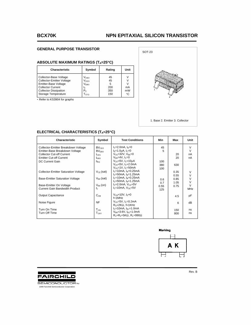
BCX70K NPN EPITAXIAL SILICON TRANSISTOR
GENERAL PURPOSE TRANSISTOR
ABSOLUTE MAXIMUM RATINGS (TA=25°°C)
• Refer to KS3904 for graphs
ELECTRICAL CHARACTERISTICS (TA=25°°C)
Characteristic Symbol Rating Unit
Collector-Base Voltage Collector-Emitter Voltage Emitter-Base Voltage Collector Current Collector Dissipation Storage Temperature
VCBO
VCEO
VEBO
IC PC
TSTG
45455
200350150
VVV
mAmW°C
Characteristic Symbol Test Conditions Min Max Unit
Collector-Emitter Breakdown VoltageEmitter-Base Breakdown VoltageCollector Cut-off CurrentEmitter Cut-off CurrentDC Current Gain
Collector-Emitter Saturation Voltage
Base-Emitter Saturation Voltage
Base-Emitter On VoltageCurrent Gain Bandwidth Product
Output Capacitance
Noise Figure
Turn On TimeTurn Off Time
BVCEO
BVEBO
ICES
IEBO
hFE
VCE (sat)
VBE (sat)
VBE (on)fT
COB
NF
TON
TOFF
IC=2.0mA, IB=0IE=1.0µA, IC=0VCE=32V, VBE=0VEB=4V, IC=0VCE=5V, IC=10µAVCE=5V, IC=2.0mAVCE=1V, IC=50mAIC=10mA, IB=0.25mAIC=50mA, IB=1.25mAIC=10mA, IB=0.25mAIC=50mA, IB=1.25mAIC=2.0mA, VCE=5VIC=10mA, VCE=5V
VCB=10V, IE=0f=1MHzVCE=5V, IC=0.2mARS=2KΩ, f=1KHzIC=10mA, IB1=1.0mAVBB=3.6V, IB2=1.0mAR1=R2=5KΩ, RL=990Ω
455
100380100
0.60.7
0.55125
2020
630
0.350.550.851.050.75
4.5
6
150800
VVnAnA
VVVVV
MHz
pF
dB
nsns
SOT-23
1. Base 2. Emitter 3. Collector
1999 Fairchild Semiconductor Corporation
Rev. B

TRADEMARKS
ACEx™CoolFET™CROSSVOLT™E2CMOSTM
FACT™FACT Quiet Series™FAST®
FASTr™GTO™HiSeC™
The following are registered and unregistered trademarks Fairchild Semiconductor owns or is authorized to use and isnot intended to be an exhaustive list of all such trademarks.
LIFE SUPPORT POLICY
FAIRCHILD’S PRODUCTS ARE NOT AUTHORIZED FOR USE AS CRITICAL COMPONENTS IN LIFE SUPPORTDEVICES OR SYSTEMS WITHOUT THE EXPRESS WRITTEN APPROVAL OF FAIRCHILD SEMICONDUCTOR CORPORATION.As used herein:
ISOPLANAR™MICROWIRE™POP™PowerTrench™QS™Quiet Series™SuperSOT™-3SuperSOT™-6SuperSOT™-8TinyLogic™
1. Life support devices or systems are devices orsystems which, (a) are intended for surgical implant intothe body, or (b) support or sustain life, or (c) whosefailure to perform when properly used in accordancewith instructions for use provided in the labeling, can bereasonably expected to result in significant injury to theuser.
2. A critical component is any component of a lifesupport device or system whose failure to perform canbe reasonably expected to cause the failure of the lifesupport device or system, or to affect its safety oreffectiveness.
PRODUCT STATUS DEFINITIONS
Definition of Terms
Datasheet Identification Product Status Definition
Advance Information
Preliminary
No Identification Needed
Obsolete
This datasheet contains the design specifications forproduct development. Specifications may change inany manner without notice.
This datasheet contains preliminary data, andsupplementary data will be published at a later date.Fairchild Semiconductor reserves the right to makechanges at any time without notice in order to improvedesign.
This datasheet contains final specifications. FairchildSemiconductor reserves the right to make changes atany time without notice in order to improve design.
This datasheet contains specifications on a productthat has been discontinued by Fairchild semiconductor.The datasheet is printed for reference information only.
Formative orIn Design
First Production
Full Production
Not In Production
DISCLAIMER
FAIRCHILD SEMICONDUCTOR RESERVES THE RIGHT TO MAKE CHANGES WITHOUT FURTHERNOTICE TO ANY PRODUCTS HEREIN TO IMPROVE RELIABILITY, FUNCTION OR DESIGN. FAIRCHILDDOES NOT ASSUME ANY LIABILITY ARISING OUT OF THE APPLICATION OR USE OF ANY PRODUCTOR CIRCUIT DESCRIBED HEREIN; NEITHER DOES IT CONVEY ANY LICENSE UNDER ITS PATENTRIGHTS, NOR THE RIGHTS OF OTHERS.
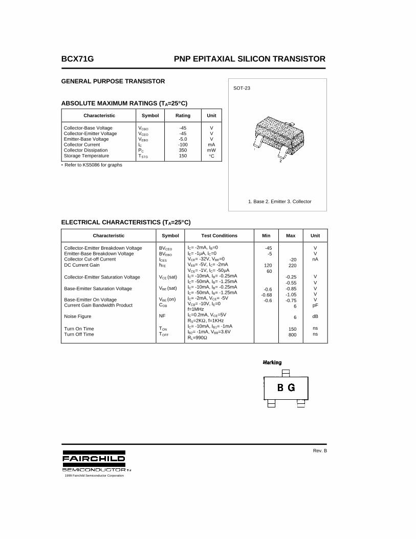
BCX71G PNP EPITAXIAL SILICON TRANSISTOR
GENERAL PURPOSE TRANSISTOR
ABSOLUTE MAXIMUM RATINGS (TA=25°°C)
• Refer to KS5086 for graphs
ELECTRICAL CHARACTERISTICS (TA=25°°C)
Characteristic Symbol Rating Unit
Collector-Base Voltage Collector-Emitter Voltage Emitter-Base Voltage Collector Current Collector Dissipation Storage Temperature
VCBO
VCEO
VEBO
IC PC
TSTG
-45-45-5.0-100350150
VVV
mAmW°C
Characteristic Symbol Test Conditions Min Max Unit
Collector-Emitter Breakdown VoltageEmitter-Base Breakdown VoltageCollector Cut-off CurrentDC Current Gain
Collector-Emitter Saturation Voltage
Base-Emitter Saturation Voltage
Base-Emitter On VoltageCurrent Gain Bandwidth Product
Noise Figure
Turn On TimeTurn Off Time
BVCEO
BVEBO
ICES
hFE
VCE (sat)
VBE (sat)
VBE (on)COB
NF
TON
TOFF
IC= -2mA, IB=0IE= -1µA, IC=0VCE= -32V, VBE=0VEB= -5V, IC= -2mAVCE= -1V, IC= -50µAIC= -10mA, IB= -0.25mAIC= -50mA, IB= -1.25mAIC= -10mA, IB= -0.25mAIC= -50mA, IB= -1.25mAIC= -2mA, VCE= -5VVCB= -10V, IE=0f=1MHzIC=0.2mA, VCE=5VRS=2KΩ, f=1KHzIC= -10mA, IB1= -1mAIB2= -1mA, VBB=3.6VRL=990Ω
-45-5
12060
-0.6-0.68-0.6
-20220
-0.25-0.55-0.85-1.05-0.75
6
6
150800
VVnA
VVVVVpF
dB
nsns
SOT-23
1. Base 2. Emitter 3. Collector
1999 Fairchild Semiconductor Corporation
Rev. B

TRADEMARKS
ACEx™CoolFET™CROSSVOLT™E2CMOSTM
FACT™FACT Quiet Series™FAST®
FASTr™GTO™HiSeC™
The following are registered and unregistered trademarks Fairchild Semiconductor owns or is authorized to use and isnot intended to be an exhaustive list of all such trademarks.
LIFE SUPPORT POLICY
FAIRCHILD’S PRODUCTS ARE NOT AUTHORIZED FOR USE AS CRITICAL COMPONENTS IN LIFE SUPPORTDEVICES OR SYSTEMS WITHOUT THE EXPRESS WRITTEN APPROVAL OF FAIRCHILD SEMICONDUCTOR CORPORATION.As used herein:
ISOPLANAR™MICROWIRE™POP™PowerTrench™QS™Quiet Series™SuperSOT™-3SuperSOT™-6SuperSOT™-8TinyLogic™
1. Life support devices or systems are devices orsystems which, (a) are intended for surgical implant intothe body, or (b) support or sustain life, or (c) whosefailure to perform when properly used in accordancewith instructions for use provided in the labeling, can bereasonably expected to result in significant injury to theuser.
2. A critical component is any component of a lifesupport device or system whose failure to perform canbe reasonably expected to cause the failure of the lifesupport device or system, or to affect its safety oreffectiveness.
PRODUCT STATUS DEFINITIONS
Definition of Terms
Datasheet Identification Product Status Definition
Advance Information
Preliminary
No Identification Needed
Obsolete
This datasheet contains the design specifications forproduct development. Specifications may change inany manner without notice.
This datasheet contains preliminary data, andsupplementary data will be published at a later date.Fairchild Semiconductor reserves the right to makechanges at any time without notice in order to improvedesign.
This datasheet contains final specifications. FairchildSemiconductor reserves the right to make changes atany time without notice in order to improve design.
This datasheet contains specifications on a productthat has been discontinued by Fairchild semiconductor.The datasheet is printed for reference information only.
Formative orIn Design
First Production
Full Production
Not In Production
DISCLAIMER
FAIRCHILD SEMICONDUCTOR RESERVES THE RIGHT TO MAKE CHANGES WITHOUT FURTHERNOTICE TO ANY PRODUCTS HEREIN TO IMPROVE RELIABILITY, FUNCTION OR DESIGN. FAIRCHILDDOES NOT ASSUME ANY LIABILITY ARISING OUT OF THE APPLICATION OR USE OF ANY PRODUCTOR CIRCUIT DESCRIBED HEREIN; NEITHER DOES IT CONVEY ANY LICENSE UNDER ITS PATENTRIGHTS, NOR THE RIGHTS OF OTHERS.
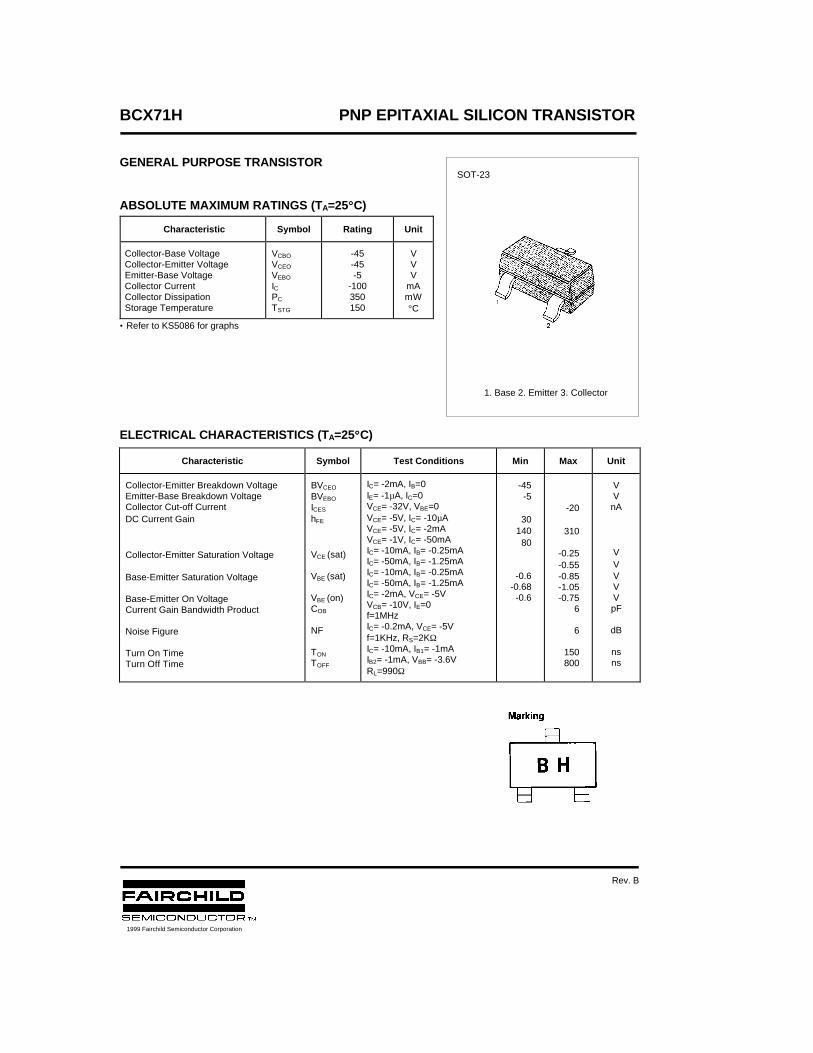
BCX71H PNP EPITAXIAL SILICON TRANSISTOR
GENERAL PURPOSE TRANSISTOR
ABSOLUTE MAXIMUM RATINGS (TA=25°°C)
• Refer to KS5086 for graphs
ELECTRICAL CHARACTERISTICS (TA=25°°C)
Characteristic Symbol Rating Unit
Collector-Base Voltage Collector-Emitter Voltage Emitter-Base Voltage Collector Current Collector Dissipation Storage Temperature
VCBO
VCEO
VEBO
ICPC
TSTG
-45-45-5
-100350150
VVV
mAmW°C
Characteristic Symbol Test Conditions Min Max Unit
Collector-Emitter Breakdown VoltageEmitter-Base Breakdown VoltageCollector Cut-off CurrentDC Current Gain
Collector-Emitter Saturation Voltage
Base-Emitter Saturation Voltage
Base-Emitter On VoltageCurrent Gain Bandwidth Product
Noise Figure
Turn On TimeTurn Off Time
BVCEO
BVEBO
ICES
hFE
VCE (sat)
VBE (sat)
VBE (on)COB
NF
TON
TOFF
IC= -2mA, IB=0IE= -1µA, IC=0VCE= -32V, VBE=0VCE= -5V, IC= -10µAVCE= -5V, IC= -2mAVCE= -1V, IC= -50mAIC= -10mA, IB= -0.25mAIC= -50mA, IB= -1.25mAIC= -10mA, IB= -0.25mAIC= -50mA, IB= -1.25mAIC= -2mA, VCE= -5VVCB= -10V, IE=0f=1MHzIC= -0.2mA, VCE= -5Vf=1KHz, RS=2KΩIC= -10mA, IB1= -1mAIB2= -1mA, VBB= -3.6VRL=990Ω
-45-5
3014080
-0.6-0.68-0.6
-20
310
-0.25-0.55-0.85-1.05-0.75
6
6
150800
VVnA
VVVVVpF
dB
nsns
SOT-23
1. Base 2. Emitter 3. Collector
1999 Fairchild Semiconductor Corporation
Rev. B

TRADEMARKS
ACEx™CoolFET™CROSSVOLT™E2CMOSTM
FACT™FACT Quiet Series™FAST®
FASTr™GTO™HiSeC™
The following are registered and unregistered trademarks Fairchild Semiconductor owns or is authorized to use and isnot intended to be an exhaustive list of all such trademarks.
LIFE SUPPORT POLICY
FAIRCHILD’S PRODUCTS ARE NOT AUTHORIZED FOR USE AS CRITICAL COMPONENTS IN LIFE SUPPORTDEVICES OR SYSTEMS WITHOUT THE EXPRESS WRITTEN APPROVAL OF FAIRCHILD SEMICONDUCTOR CORPORATION.As used herein:
ISOPLANAR™MICROWIRE™POP™PowerTrench™QS™Quiet Series™SuperSOT™-3SuperSOT™-6SuperSOT™-8TinyLogic™
1. Life support devices or systems are devices orsystems which, (a) are intended for surgical implant intothe body, or (b) support or sustain life, or (c) whosefailure to perform when properly used in accordancewith instructions for use provided in the labeling, can bereasonably expected to result in significant injury to theuser.
2. A critical component is any component of a lifesupport device or system whose failure to perform canbe reasonably expected to cause the failure of the lifesupport device or system, or to affect its safety oreffectiveness.
PRODUCT STATUS DEFINITIONS
Definition of Terms
Datasheet Identification Product Status Definition
Advance Information
Preliminary
No Identification Needed
Obsolete
This datasheet contains the design specifications forproduct development. Specifications may change inany manner without notice.
This datasheet contains preliminary data, andsupplementary data will be published at a later date.Fairchild Semiconductor reserves the right to makechanges at any time without notice in order to improvedesign.
This datasheet contains final specifications. FairchildSemiconductor reserves the right to make changes atany time without notice in order to improve design.
This datasheet contains specifications on a productthat has been discontinued by Fairchild semiconductor.The datasheet is printed for reference information only.
Formative orIn Design
First Production
Full Production
Not In Production
DISCLAIMER
FAIRCHILD SEMICONDUCTOR RESERVES THE RIGHT TO MAKE CHANGES WITHOUT FURTHERNOTICE TO ANY PRODUCTS HEREIN TO IMPROVE RELIABILITY, FUNCTION OR DESIGN. FAIRCHILDDOES NOT ASSUME ANY LIABILITY ARISING OUT OF THE APPLICATION OR USE OF ANY PRODUCTOR CIRCUIT DESCRIBED HEREIN; NEITHER DOES IT CONVEY ANY LICENSE UNDER ITS PATENTRIGHTS, NOR THE RIGHTS OF OTHERS.
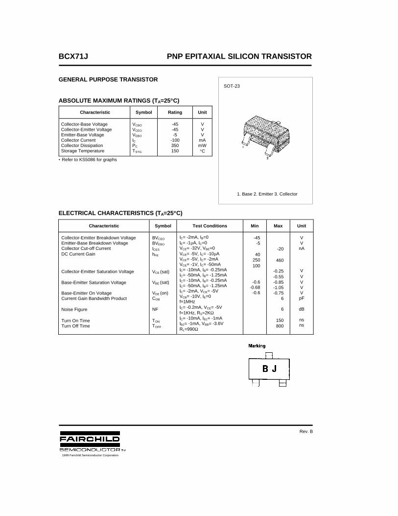
BCX71J PNP EPITAXIAL SILICON TRANSISTOR
GENERAL PURPOSE TRANSISTOR
ABSOLUTE MAXIMUM RATINGS (TA=25°°C)
• Refer to KS5086 for graphs
ELECTRICAL CHARACTERISTICS (TA=25°°C)
Characteristic Symbol Rating Unit
Collector-Base Voltage Collector-Emitter Voltage Emitter-Base Voltage Collector Current Collector Dissipation Storage Temperature
VCBO
VCEO
VEBO
IC PC
TSTG
-45-45-5
-100350150
VVV
mAmW°C
Characteristic Symbol Test Conditions Min Max Unit
Collector-Emitter Breakdown VoltageEmitter-Base Breakdown VoltageCollector Cut-off CurrentDC Current Gain
Collector-Emitter Saturation Voltage
Base-Emitter Saturation Voltage
Base-Emitter On VoltageCurrent Gain Bandwidth Product
Noise Figure
Turn On TimeTurn Off Time
BVCEO
BVEBO
ICES
hFE
VCE (sat)
VBE (sat)
VDE (on)COB
NF
TON
TOFF
IC= -2mA, IB=0IE= -1µA, IC=0VCE= -32V, VBE=0VCE= -5V, IC= -10µAVCE= -5V, IC= -2mAVCE= -1V, IC= -50mAIC= -10mA, IB= -0.25mAIC= -50mA, IB= -1.25mAIC= -10mA, IB= -0.25mAIC= -50mA, IB= -1.25mAIC= -2mA, VCE= -5VVCB= -10V, IE=0f=1MHzIC= -0.2mA, VCE= -5Vf=1KHz, RS=2KΩIC= -10mA, IB1= -1mAIB2= -1mA, VBB= -3.6VRL=990Ω
-45-5
40250100
-0.6-0.68-0.6
-20
460
-0.25-0.55-0.85-1.05-0.75
6
6
150800
VVnA
VVVVVpF
dB
nsns
SOT-23
1. Base 2. Emitter 3. Collector
1999 Fairchild Semiconductor Corporation
Rev. B

TRADEMARKS
ACEx™CoolFET™CROSSVOLT™E2CMOSTM
FACT™FACT Quiet Series™FAST®
FASTr™GTO™HiSeC™
The following are registered and unregistered trademarks Fairchild Semiconductor owns or is authorized to use and isnot intended to be an exhaustive list of all such trademarks.
LIFE SUPPORT POLICY
FAIRCHILD’S PRODUCTS ARE NOT AUTHORIZED FOR USE AS CRITICAL COMPONENTS IN LIFE SUPPORTDEVICES OR SYSTEMS WITHOUT THE EXPRESS WRITTEN APPROVAL OF FAIRCHILD SEMICONDUCTOR CORPORATION.As used herein:
ISOPLANAR™MICROWIRE™POP™PowerTrench™QS™Quiet Series™SuperSOT™-3SuperSOT™-6SuperSOT™-8TinyLogic™
1. Life support devices or systems are devices orsystems which, (a) are intended for surgical implant intothe body, or (b) support or sustain life, or (c) whosefailure to perform when properly used in accordancewith instructions for use provided in the labeling, can bereasonably expected to result in significant injury to theuser.
2. A critical component is any component of a lifesupport device or system whose failure to perform canbe reasonably expected to cause the failure of the lifesupport device or system, or to affect its safety oreffectiveness.
PRODUCT STATUS DEFINITIONS
Definition of Terms
Datasheet Identification Product Status Definition
Advance Information
Preliminary
No Identification Needed
Obsolete
This datasheet contains the design specifications forproduct development. Specifications may change inany manner without notice.
This datasheet contains preliminary data, andsupplementary data will be published at a later date.Fairchild Semiconductor reserves the right to makechanges at any time without notice in order to improvedesign.
This datasheet contains final specifications. FairchildSemiconductor reserves the right to make changes atany time without notice in order to improve design.
This datasheet contains specifications on a productthat has been discontinued by Fairchild semiconductor.The datasheet is printed for reference information only.
Formative orIn Design
First Production
Full Production
Not In Production
DISCLAIMER
FAIRCHILD SEMICONDUCTOR RESERVES THE RIGHT TO MAKE CHANGES WITHOUT FURTHERNOTICE TO ANY PRODUCTS HEREIN TO IMPROVE RELIABILITY, FUNCTION OR DESIGN. FAIRCHILDDOES NOT ASSUME ANY LIABILITY ARISING OUT OF THE APPLICATION OR USE OF ANY PRODUCTOR CIRCUIT DESCRIBED HEREIN; NEITHER DOES IT CONVEY ANY LICENSE UNDER ITS PATENTRIGHTS, NOR THE RIGHTS OF OTHERS.
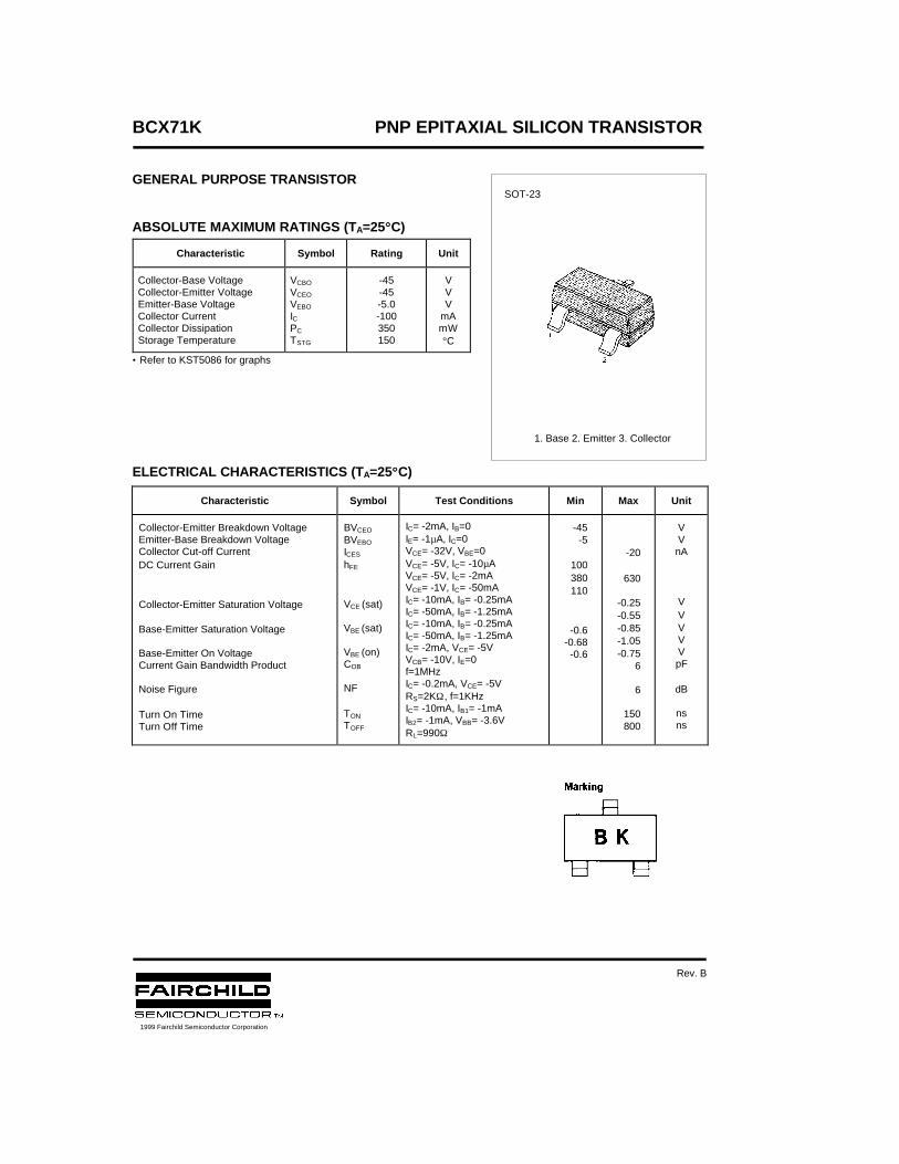
BCX71K PNP EPITAXIAL SILICON TRANSISTOR
GENERAL PURPOSE TRANSISTOR
ABSOLUTE MAXIMUM RATINGS (TA=25°°C)
• Refer to KST5086 for graphs
ELECTRICAL CHARACTERISTICS (TA=25°°C)
Characteristic Symbol Rating Unit
Collector-Base Voltage Collector-Emitter Voltage Emitter-Base Voltage Collector Current Collector Dissipation Storage Temperature
VCBO
VCEO
VEBO
IC PC
TSTG
-45-45-5.0-100350150
VVV
mAmW°C
Characteristic Symbol Test Conditions Min Max Unit
Collector-Emitter Breakdown VoltageEmitter-Base Breakdown VoltageCollector Cut-off CurrentDC Current Gain
Collector-Emitter Saturation Voltage
Base-Emitter Saturation Voltage
Base-Emitter On VoltageCurrent Gain Bandwidth Product
Noise Figure
Turn On TimeTurn Off Time
BVCEO
BVEBO
ICES
hFE
VCE (sat)
VBE (sat)
VBE (on)COB
NF
TON
TOFF
IC= -2mA, IB=0IE= -1µA, IC=0VCE= -32V, VBE=0VCE= -5V, IC= -10µAVCE= -5V, IC= -2mAVCE= -1V, IC= -50mAIC= -10mA, IB= -0.25mAIC= -50mA, IB= -1.25mAIC= -10mA, IB= -0.25mAIC= -50mA, IB= -1.25mAIC= -2mA, VCE= -5VVCB= -10V, IE=0f=1MHzIC= -0.2mA, VCE= -5VRS=2KΩ, f=1KHzIC= -10mA, IB1= -1mAIB2= -1mA, VBB= -3.6VRL=990Ω
-45-5
100380110
-0.6-0.68-0.6
-20
630
-0.25-0.55-0.85-1.05-0.75
6
6
150800
VVnA
VVVVVpF
dB
nsns
SOT-23
1. Base 2. Emitter 3. Collector
1999 Fairchild Semiconductor Corporation
Rev. B

TRADEMARKS
ACEx™CoolFET™CROSSVOLT™E2CMOSTM
FACT™FACT Quiet Series™FAST®
FASTr™GTO™HiSeC™
The following are registered and unregistered trademarks Fairchild Semiconductor owns or is authorized to use and isnot intended to be an exhaustive list of all such trademarks.
LIFE SUPPORT POLICY
FAIRCHILD’S PRODUCTS ARE NOT AUTHORIZED FOR USE AS CRITICAL COMPONENTS IN LIFE SUPPORTDEVICES OR SYSTEMS WITHOUT THE EXPRESS WRITTEN APPROVAL OF FAIRCHILD SEMICONDUCTOR CORPORATION.As used herein:
ISOPLANAR™MICROWIRE™POP™PowerTrench™QS™Quiet Series™SuperSOT™-3SuperSOT™-6SuperSOT™-8TinyLogic™
1. Life support devices or systems are devices orsystems which, (a) are intended for surgical implant intothe body, or (b) support or sustain life, or (c) whosefailure to perform when properly used in accordancewith instructions for use provided in the labeling, can bereasonably expected to result in significant injury to theuser.
2. A critical component is any component of a lifesupport device or system whose failure to perform canbe reasonably expected to cause the failure of the lifesupport device or system, or to affect its safety oreffectiveness.
PRODUCT STATUS DEFINITIONS
Definition of Terms
Datasheet Identification Product Status Definition
Advance Information
Preliminary
No Identification Needed
Obsolete
This datasheet contains the design specifications forproduct development. Specifications may change inany manner without notice.
This datasheet contains preliminary data, andsupplementary data will be published at a later date.Fairchild Semiconductor reserves the right to makechanges at any time without notice in order to improvedesign.
This datasheet contains final specifications. FairchildSemiconductor reserves the right to make changes atany time without notice in order to improve design.
This datasheet contains specifications on a productthat has been discontinued by Fairchild semiconductor.The datasheet is printed for reference information only.
Formative orIn Design
First Production
Full Production
Not In Production
DISCLAIMER
FAIRCHILD SEMICONDUCTOR RESERVES THE RIGHT TO MAKE CHANGES WITHOUT FURTHERNOTICE TO ANY PRODUCTS HEREIN TO IMPROVE RELIABILITY, FUNCTION OR DESIGN. FAIRCHILDDOES NOT ASSUME ANY LIABILITY ARISING OUT OF THE APPLICATION OR USE OF ANY PRODUCTOR CIRCUIT DESCRIBED HEREIN; NEITHER DOES IT CONVEY ANY LICENSE UNDER ITS PATENTRIGHTS, NOR THE RIGHTS OF OTHERS.
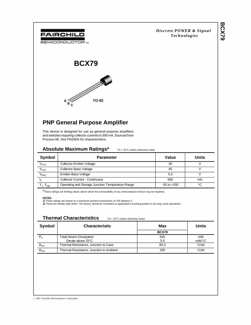
BC
X79
Discrete POWER & SignalTechnologies
PNP General Purpose Amplifier
BCX79
This device is designed for use as general purpose amplifiersand switches requiring collector currents to 300 mA. Sourced fromProcess 68. See PN200A for characteristics.
Absolute Maximum Ratings* TA = 25°C unless otherwise noted
*These ratings are limiting values above which the serviceability of any semiconductor device may be impaired.
NOTES:1) These ratings are based on a maximum junction temperature of 150 degrees C.2) These are steady state limits. The factory should be consulted on applications involving pulsed or low duty cycle operations.
Thermal Characteristics TA = 25°C unless otherwise noted
Symbol Parameter Value UnitsVCEO Collector-Emitter Voltage 45 V
VCES Collector-Base Voltage 45 V
VEBO Emitter-Base Voltage 5.0 V
IC Collector Current - Continuous 500 mA
TJ, Tstg Operating and Storage Junction Temperature Range -55 to +150 °C
Symbol Characteristic Max UnitsBCX79
PD Total Device DissipationDerate above 25°C
6255.0
mWmW/°C
RθJC Thermal Resistance, Junction to Case 83.3 °C/W
RθJA Thermal Resistance, Junction to Ambient 200 °C/W
EB C
TO-92
1997 Fairchild Semiconductor Corporation
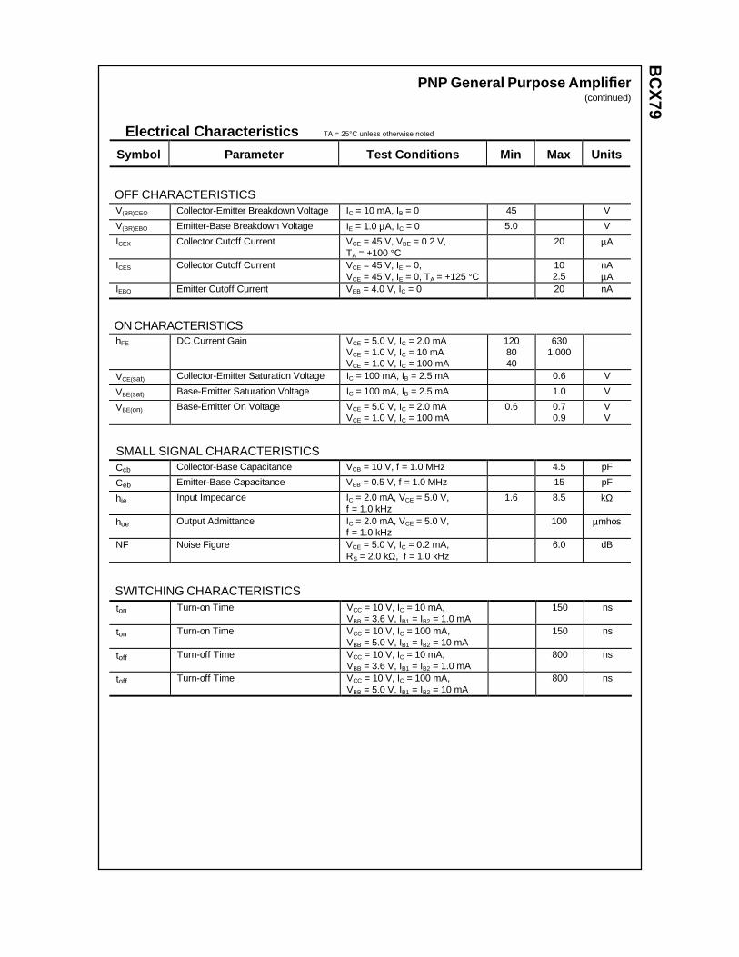
BC
X79
PNP General Purpose Amplifier(continued)
Electrical Characteristics TA = 25°C unless otherwise noted
OFF CHARACTERISTICS
Symbol Parameter Test C onditions Min Max Units
V(BR)CEO Collector-Emitter Breakdown Voltage IC = 10 mA, IB = 0 45 V
V(BR)EBO Emitter-Base Breakdown Voltage IE = 1.0 µA, IC = 0 5.0 V
ICEX Collector Cutoff Current VCE = 45 V, VBE = 0.2 V,TA = +100 °C
20 µA
ICES Collector Cutoff Current VCE = 45 V, IE = 0,VCE = 45 V, IE = 0, TA = +125 °C
102.5
nAµA
IEBO Emitter Cutoff Current VEB = 4.0 V, IC = 0 20 nA
ON CHARACTERISTICShFE DC Current Gain VCE = 5.0 V, IC = 2.0 mA
VCE = 1.0 V, IC = 10 mAVCE = 1.0 V, IC = 100 mA
1208040
6301,000
VCE(sat) Collector-Emitter Saturation Voltage IC = 100 mA, IB = 2.5 mA 0.6 V
VBE(sat) Base-Emitter Saturation Voltage IC = 100 mA, IB = 2.5 mA 1.0 V
VBE(on) Base-Emitter On Voltage VCE = 5.0 V, IC = 2.0 mAVCE = 1.0 V, IC = 100 mA
0.6 0.70.9
VV
SMALL SIGNAL CHARACTERISTICSCcb Collector-Base Capacitance VCB = 10 V, f = 1.0 MHz 4.5 pF
Ceb Emitter-Base Capacitance VEB = 0.5 V, f = 1.0 MHz 15 pF
hie Input Impedance IC = 2.0 mA, VCE = 5.0 V,f = 1.0 kHz
1.6 8.5 kΩ
hoe Output Admittance IC = 2.0 mA, VCE = 5.0 V,f = 1.0 kHz
100 µmhos
NF Noise Figure VCE = 5.0 V, IC = 0.2 mA,RS = 2.0 kΩ, f = 1.0 kHz
6.0 dB
SWITCHING CHARACTERISTICSton Turn-on Time VCC = 10 V, IC = 10 mA,
VBB = 3.6 V, IB1 = IB2 = 1.0 mA150 ns
ton Turn-on Time VCC = 10 V, IC = 100 mA,VBB = 5.0 V, IB1 = IB2 = 10 mA
150 ns
toff Turn-off Time VCC = 10 V, IC = 10 mA,VBB = 3.6 V, IB1 = IB2 = 1.0 mA
800 ns
toff Turn-off Time VCC = 10 V, IC = 100 mA,VBB = 5.0 V, IB1 = IB2 = 10 mA
800 ns