Embed Size (px)
Citation preview
Page 1
Section 3
INDEX OF ATTACHMENTS 1(a) Modification Codes for Commercial Vehicle Modifications 2 1(b) Modification Codes for Light Vehicle Modifications 4 2 Australian Design Rule (ADR) Seat Belt Requirements 5 3 Mudguard and Mudflap Requirements 16 4 Headlamp Testing Screens 18 5 Missing Compliance Plates 19 6 LPG and CNG Certification 21 7 Braided Brake Hoses 23 8 Motor Vehicle Lighting 25 9 Rear Marking Plates 27 10 Replacing or Repairing Windscreens 36 11 Rust and Corrosion 40 12(a) Safety Chains for trailers less than 3.5 tonnes ATM 46 12(b) Safety Chains for trailers 3.5 tonnes ATM and above and for rigid draw bar pig trailers above 2.5 tonnes GTM and fitted with automatic pin type couplings 47 13 Ground Clearance Requirements 52 14 ADR Applicability Tables, Vehicle Categories and Definitions 53 15 Retreaded Tyres 67 16 Brake drums and discs 71 17 Replacement Steering Wheels 75 18 Fitting of body lift kits and suspension height modifications to motor vehicles 78 19 Commercial Vehicle Modifications carried out prior to 1990 80 20 Suspension Modifications 82 21 Lighting Standards 85
Page 2
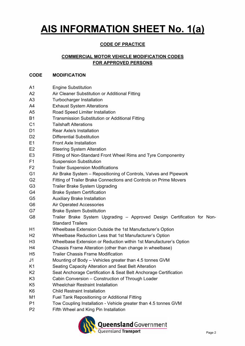
AIS INFORMATION SHEET No. 1(a)
CODE OF PRACTICE
COMMERCIAL MOTOR VEHICLE MODIFICATION CODES FOR APPROVED PERSONS
CODE MODIFICATION A1 Engine Substitution A2 Air Cleaner Substitution or Additional Fitting A3 Turbocharger Installation A4 Exhaust System Alterations A5 Road Speed Limiter Installation B1 Transmission Substitution or Additional Fitting C1 Tailshaft Alterations D1 Rear Axle/s Installation D2 Differential Substitution E1 Front Axle Installation E2 Steering System Alteration E3 Fitting of Non-Standard Front Wheel Rims and Tyre Componentry F1 Suspension Substitution F2 Trailer Suspension Modifications G1 Air Brake System – Repositioning of Controls, Valves and Pipework G2 Fitting of Trailer Brake Connections and Controls on Prime Movers G3 Trailer Brake System Upgrading G4 Brake System Certification G5 Auxiliary Brake Installation G6 Air Operated Accessories G7 Brake System Substitution G8 Trailer Brake System Upgrading – Approved Design Certification for Non-
Standard Trailers H1 Wheelbase Extension Outside the 1st Manufacturer’s Option H2 Wheelbase Reduction Less that 1st Manufacturer’s Option H3 Wheelbase Extension or Reduction within 1st Manufacturer’s Option H4 Chassis Frame Alteration (other than change in wheelbase) H5 Trailer Chassis Frame Modification J1 Mounting of Body – Vehicles greater than 4.5 tonnes GVM K1 Seating Capacity Alteration and Seat Belt Alteration K2 Seat Anchorage Certification & Seat Belt Anchorage Certification K3 Cabin Conversion – Construction of Through Loader K5 Wheelchair Restraint Installation K6 Child Restraint Installation M1 Fuel Tank Repositioning or Additional Fitting P1 Tow Coupling Installation - Vehicle greater than 4.5 tonnes GVM P2 Fifth Wheel and King Pin Installation
Page 3
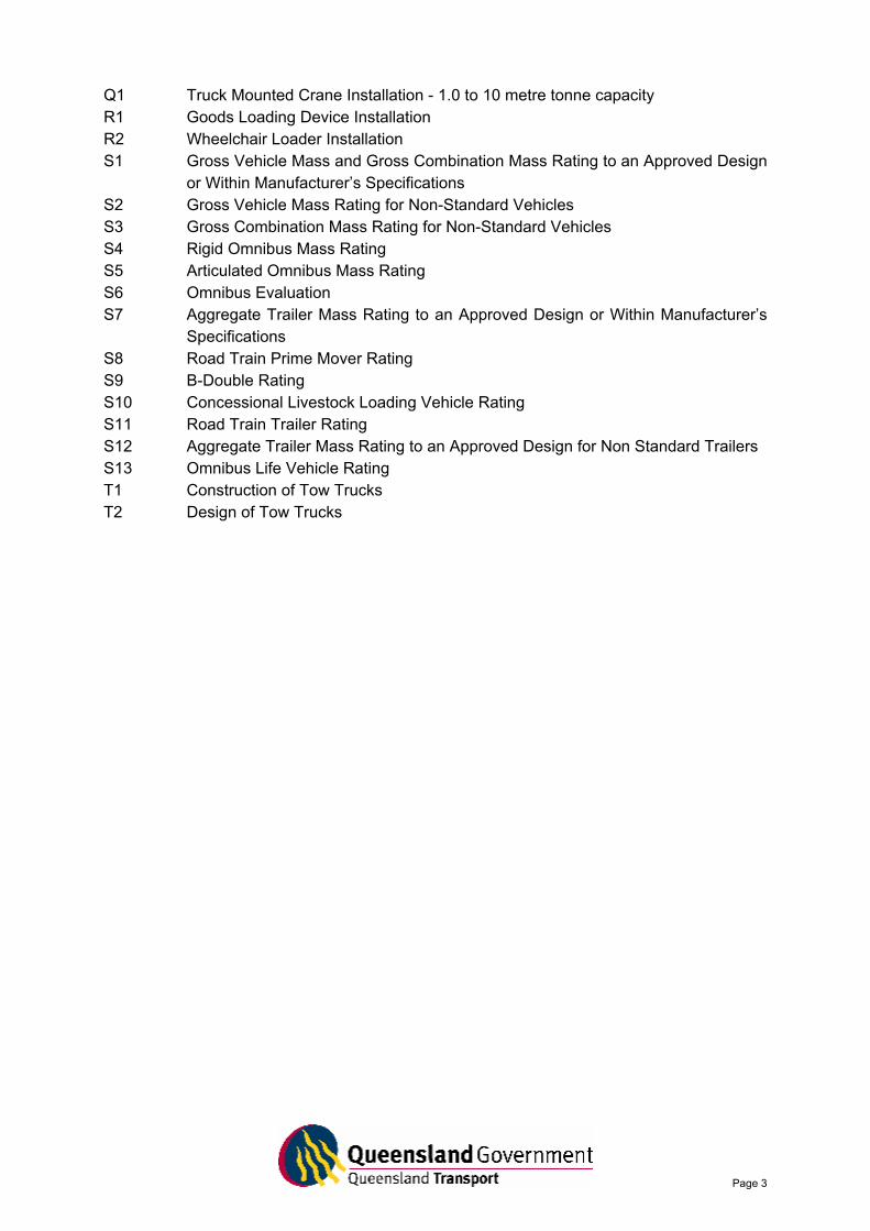
Q1 Truck Mounted Crane Installation - 1.0 to 10 metre tonne capacity R1 Goods Loading Device Installation R2 Wheelchair Loader Installation S1 Gross Vehicle Mass and Gross Combination Mass Rating to an Approved Design
or Within Manufacturer’s Specifications S2 Gross Vehicle Mass Rating for Non-Standard Vehicles S3 Gross Combination Mass Rating for Non-Standard Vehicles S4 Rigid Omnibus Mass Rating S5 Articulated Omnibus Mass Rating S6 Omnibus Evaluation S7 Aggregate Trailer Mass Rating to an Approved Design or Within Manufacturer’s
Specifications S8 Road Train Prime Mover Rating S9 B-Double Rating S10 Concessional Livestock Loading Vehicle Rating S11 Road Train Trailer Rating S12 Aggregate Trailer Mass Rating to an Approved Design for Non Standard Trailers S13 Omnibus Life Vehicle Rating T1 Construction of Tow Trucks T2 Design of Tow Trucks
Page 4
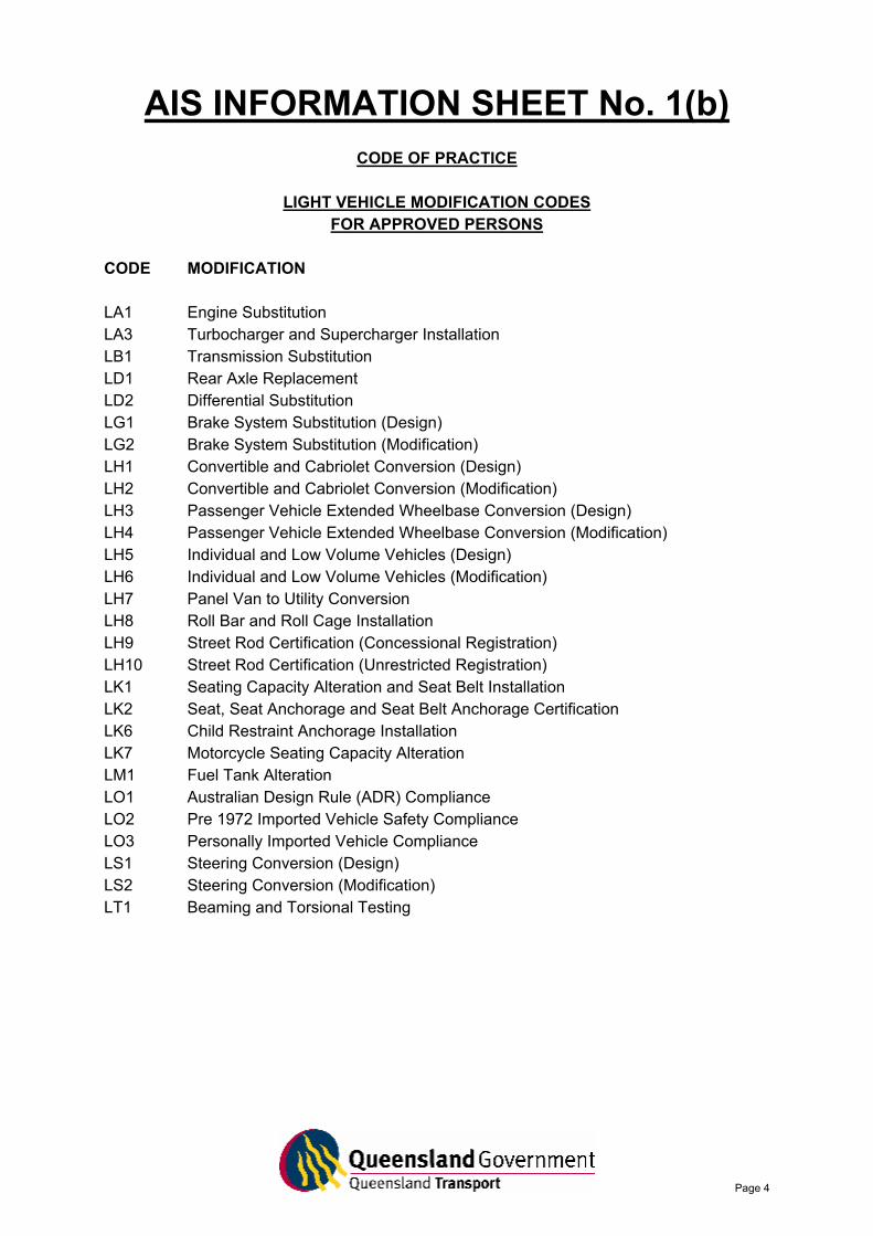
AIS INFORMATION SHEET No. 1(b)
CODE OF PRACTICE
LIGHT VEHICLE MODIFICATION CODES FOR APPROVED PERSONS
CODE MODIFICATION LA1 Engine Substitution LA3 Turbocharger and Supercharger Installation LB1 Transmission Substitution LD1 Rear Axle Replacement LD2 Differential Substitution LG1 Brake System Substitution (Design) LG2 Brake System Substitution (Modification) LH1 Convertible and Cabriolet Conversion (Design) LH2 Convertible and Cabriolet Conversion (Modification) LH3 Passenger Vehicle Extended Wheelbase Conversion (Design) LH4 Passenger Vehicle Extended Wheelbase Conversion (Modification) LH5 Individual and Low Volume Vehicles (Design) LH6 Individual and Low Volume Vehicles (Modification) LH7 Panel Van to Utility Conversion LH8 Roll Bar and Roll Cage Installation LH9 Street Rod Certification (Concessional Registration) LH10 Street Rod Certification (Unrestricted Registration) LK1 Seating Capacity Alteration and Seat Belt Installation LK2 Seat, Seat Anchorage and Seat Belt Anchorage Certification LK6 Child Restraint Anchorage Installation LK7 Motorcycle Seating Capacity Alteration LM1 Fuel Tank Alteration LO1 Australian Design Rule (ADR) Compliance LO2 Pre 1972 Imported Vehicle Safety Compliance LO3 Personally Imported Vehicle Compliance LS1 Steering Conversion (Design) LS2 Steering Conversion (Modification) LT1 Beaming and Torsional Testing
Page 5
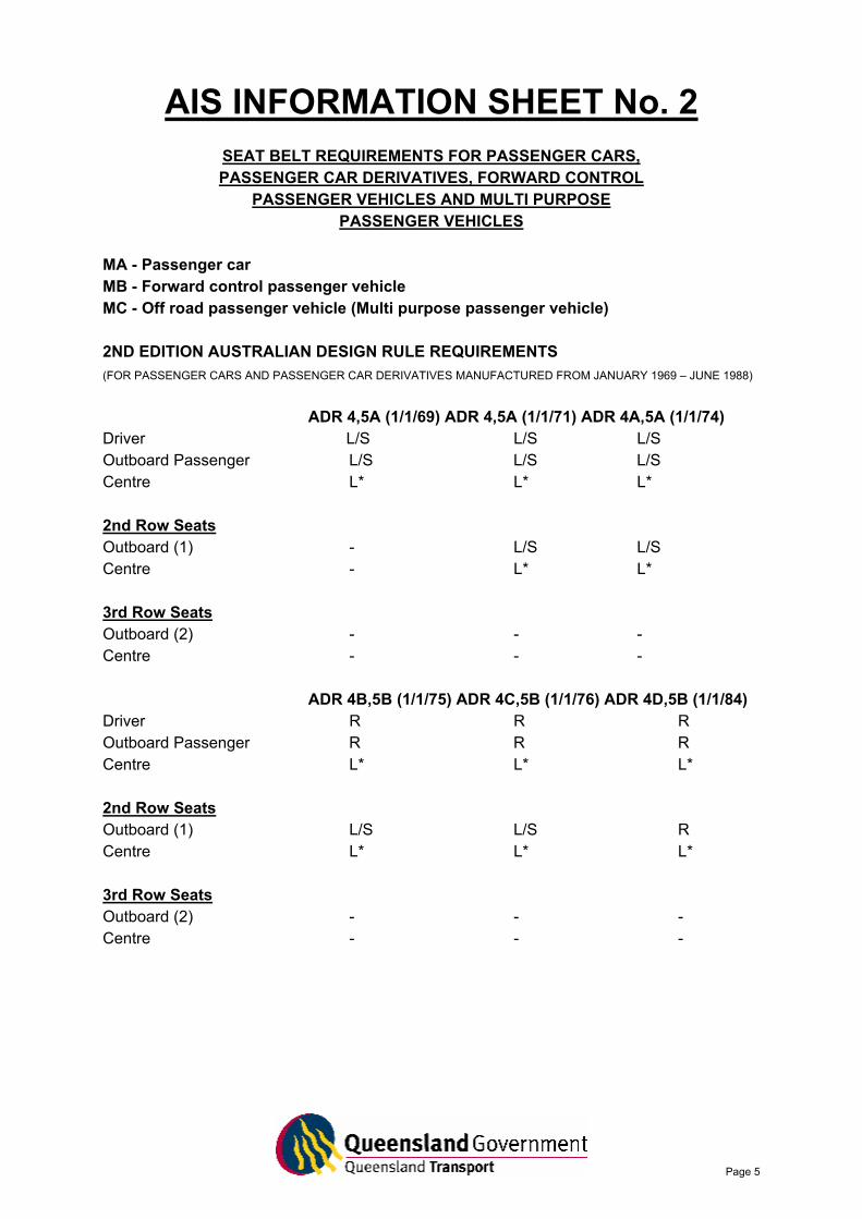
AIS INFORMATION SHEET No. 2
SEAT BELT REQUIREMENTS FOR PASSENGER CARS, PASSENGER CAR DERIVATIVES, FORWARD CONTROL
PASSENGER VEHICLES AND MULTI PURPOSE PASSENGER VEHICLES
MA - Passenger car MB - Forward control passenger vehicle MC - Off road passenger vehicle (Multi purpose passenger vehicle) 2ND EDITION AUSTRALIAN DESIGN RULE REQUIREMENTS (FOR PASSENGER CARS AND PASSENGER CAR DERIVATIVES MANUFACTURED FROM JANUARY 1969 – JUNE 1988)
ADR 4,5A (1/1/69) ADR 4,5A (1/1/71) ADR 4A,5A (1/1/74)
Driver L/S L/S L/S Outboard Passenger L/S L/S L/S Centre L* L* L* 2nd Row Seats Outboard (1) - L/S L/S Centre - L* L* 3rd Row Seats Outboard (2) - - - Centre - - -
ADR 4B,5B (1/1/75) ADR 4C,5B (1/1/76) ADR 4D,5B (1/1/84) Driver R R R Outboard Passenger R R R Centre L* L* L* 2nd Row Seats Outboard (1) L/S L/S R Centre L* L* L* 3rd Row Seats Outboard (2) - - - Centre - - -
Page 6
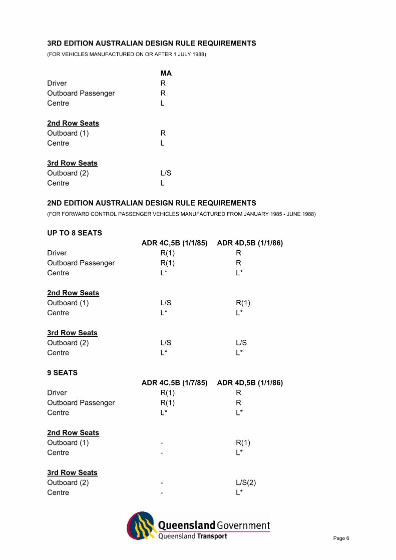
3RD EDITION AUSTRALIAN DESIGN RULE REQUIREMENTS (FOR VEHICLES MANUFACTURED ON OR AFTER 1 JULY 1988)
MA
Driver R Outboard Passenger R Centre L 2nd Row Seats Outboard (1) R Centre L 3rd Row Seats Outboard (2) L/S Centre L 2ND EDITION AUSTRALIAN DESIGN RULE REQUIREMENTS (FOR FORWARD CONTROL PASSENGER VEHICLES MANUFACTURED FROM JANUARY 1985 - JUNE 1988)
UP TO 8 SEATS
ADR 4C,5B (1/1/85) ADR 4D,5B (1/1/86) Driver R(1) R Outboard Passenger R(1) R Centre L* L* 2nd Row Seats Outboard (1) L/S R(1) Centre L* L* 3rd Row Seats Outboard (2) L/S L/S Centre L* L* 9 SEATS
ADR 4C,5B (1/7/85) ADR 4D,5B (1/1/86) Driver R(1) R Outboard Passenger R(1) R Centre L* L* 2nd Row Seats Outboard (1) - R(1) Centre - L* 3rd Row Seats Outboard (2) - L/S(2) Centre - L*
Page 7
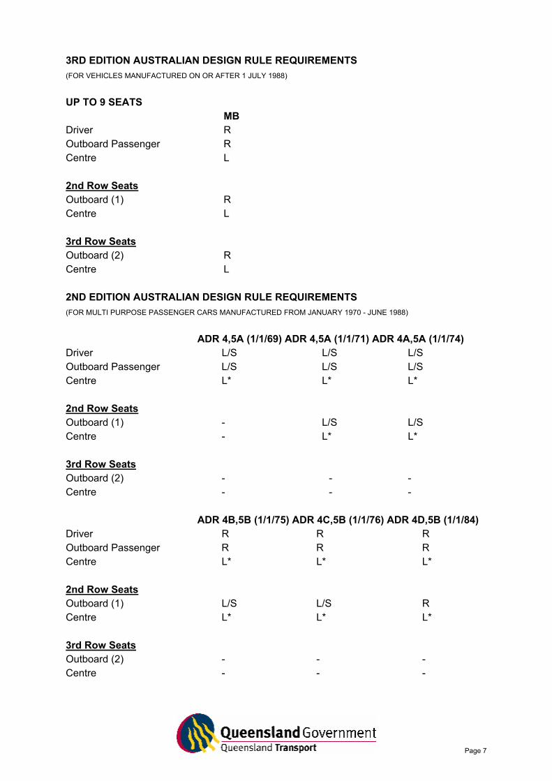
3RD EDITION AUSTRALIAN DESIGN RULE REQUIREMENTS (FOR VEHICLES MANUFACTURED ON OR AFTER 1 JULY 1988)
UP TO 9 SEATS
MB Driver R Outboard Passenger R Centre L 2nd Row Seats Outboard (1) R Centre L 3rd Row Seats Outboard (2) R Centre L 2ND EDITION AUSTRALIAN DESIGN RULE REQUIREMENTS (FOR MULTI PURPOSE PASSENGER CARS MANUFACTURED FROM JANUARY 1970 - JUNE 1988)
ADR 4,5A (1/1/69) ADR 4,5A (1/1/71) ADR 4A,5A (1/1/74)
Driver L/S L/S L/S Outboard Passenger L/S L/S L/S Centre L* L* L* 2nd Row Seats Outboard (1) - L/S L/S Centre - L* L* 3rd Row Seats Outboard (2) - - - Centre - - -
ADR 4B,5B (1/1/75) ADR 4C,5B (1/1/76) ADR 4D,5B (1/1/84) Driver R R R Outboard Passenger R R R Centre L* L* L* 2nd Row Seats Outboard (1) L/S L/S R Centre L* L* L* 3rd Row Seats Outboard (2) - - - Centre - - -
Page 8
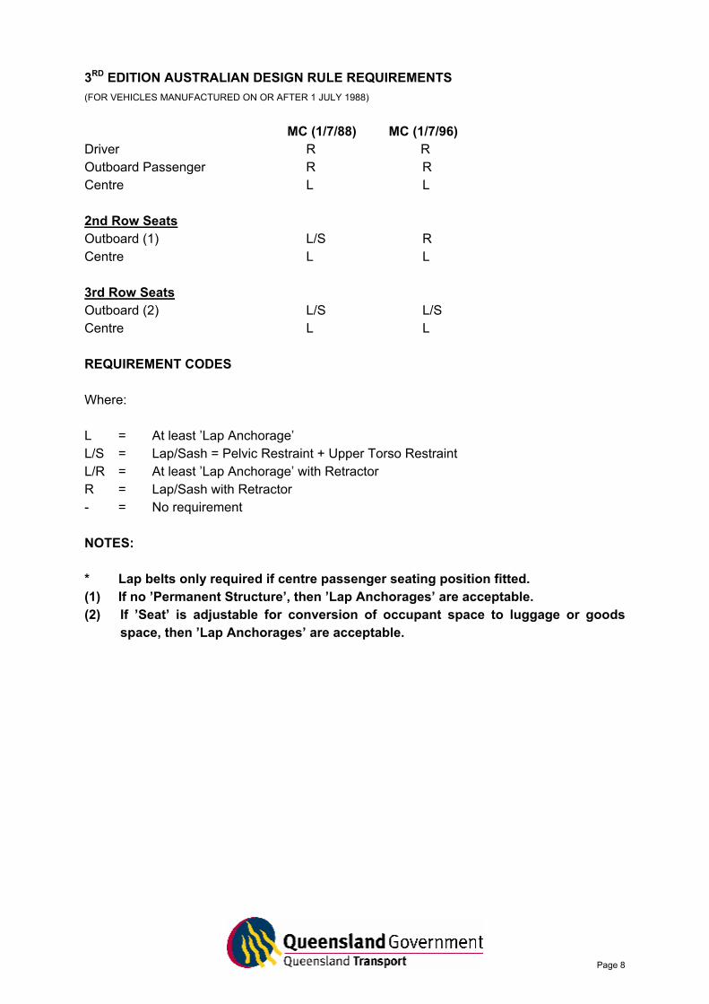
3RD EDITION AUSTRALIAN DESIGN RULE REQUIREMENTS (FOR VEHICLES MANUFACTURED ON OR AFTER 1 JULY 1988)
MC (1/7/88) MC (1/7/96)
Driver R R Outboard Passenger R R Centre L L 2nd Row Seats Outboard (1) L/S R Centre L L 3rd Row Seats Outboard (2) L/S L/S Centre L L REQUIREMENT CODES Where: L = At least ’Lap Anchorage’ L/S = Lap/Sash = Pelvic Restraint + Upper Torso Restraint L/R = At least ’Lap Anchorage’ with Retractor R = Lap/Sash with Retractor - = No requirement NOTES: * Lap belts only required if centre passenger seating position fitted. (1) If no ’Permanent Structure’, then ’Lap Anchorages’ are acceptable. (2) If ’Seat’ is adjustable for conversion of occupant space to luggage or goods
space, then ’Lap Anchorages’ are acceptable.
Page 9
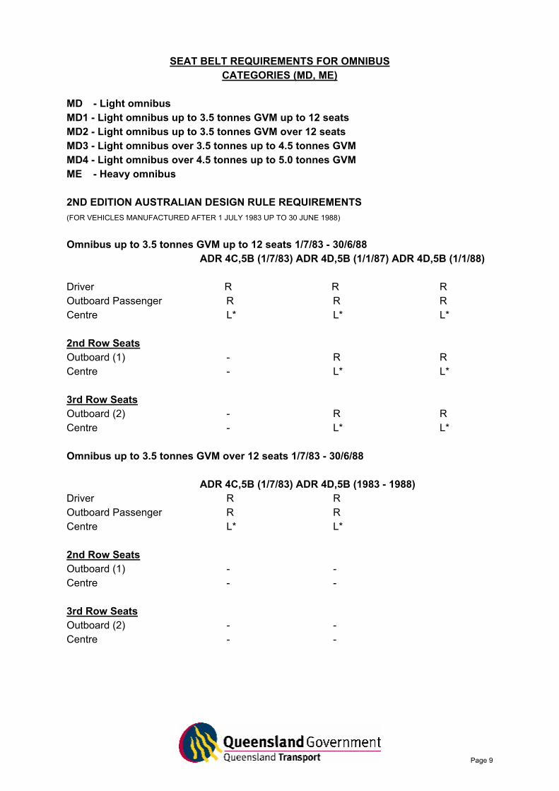
SEAT BELT REQUIREMENTS FOR OMNIBUS CATEGORIES (MD, ME)
MD - Light omnibus MD1 - Light omnibus up to 3.5 tonnes GVM up to 12 seats MD2 - Light omnibus up to 3.5 tonnes GVM over 12 seats MD3 - Light omnibus over 3.5 tonnes up to 4.5 tonnes GVM MD4 - Light omnibus over 4.5 tonnes up to 5.0 tonnes GVM ME - Heavy omnibus 2ND EDITION AUSTRALIAN DESIGN RULE REQUIREMENTS (FOR VEHICLES MANUFACTURED AFTER 1 JULY 1983 UP TO 30 JUNE 1988)
Omnibus up to 3.5 tonnes GVM up to 12 seats 1/7/83 - 30/6/88
ADR 4C,5B (1/7/83) ADR 4D,5B (1/1/87) ADR 4D,5B (1/1/88) Driver R R R Outboard Passenger R R R Centre L* L* L* 2nd Row Seats Outboard (1) - R R Centre - L* L* 3rd Row Seats Outboard (2) - R R Centre - L* L* Omnibus up to 3.5 tonnes GVM over 12 seats 1/7/83 - 30/6/88
ADR 4C,5B (1/7/83) ADR 4D,5B (1983 - 1988) Driver R R Outboard Passenger R R Centre L* L* 2nd Row Seats Outboard (1) - - Centre - - 3rd Row Seats Outboard (2) - - Centre - -

Page 10
Omnibus up to 4.5 tonnes Gross Vehicle Mass 1/7/87 - 30/6/88 Omnibus over 4.5 tonnes Gross Vehicle Mass 1/7/87 - 30/6/88
ADR 32A (1/7/87) Driver L Outboard Passenger L Centre - 2nd Row Seats Outboard (1) - Centre - 3rd Row Seats Outboard (2) - Centre - 3RD EDITION AUSTRALIAN DESIGN RULE REQUIREMENTS (ADR 5/00) (FOR VEHICLES MANUFACTURED ON OR AFTER 1 JULY 1988 TO 30 JUNE 1990)
MD1 MD2 MD3 MD4 ME
Driver R R L(1) L(1) L(1) Outboard Passenger R R - - - Centre L L - - - 2nd Row Seats Outboard (1) R - - - - Centre L - - - - 3rd Row Seats Outboard (2) R - - - - Centre L - - - -
Page 11
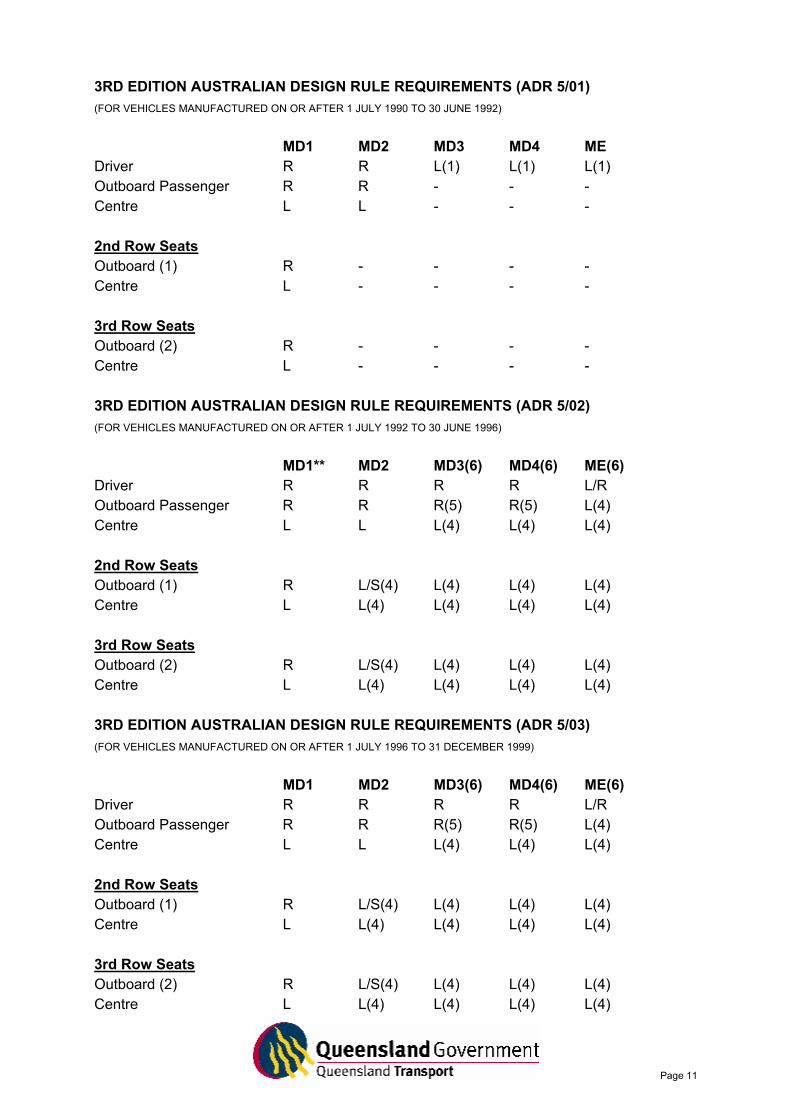
3RD EDITION AUSTRALIAN DESIGN RULE REQUIREMENTS (ADR 5/01) (FOR VEHICLES MANUFACTURED ON OR AFTER 1 JULY 1990 TO 30 JUNE 1992)
MD1 MD2 MD3 MD4 ME
Driver R R L(1) L(1) L(1) Outboard Passenger R R - - - Centre L L - - - 2nd Row Seats Outboard (1) R - - - - Centre L - - - - 3rd Row Seats Outboard (2) R - - - - Centre L - - - - 3RD EDITION AUSTRALIAN DESIGN RULE REQUIREMENTS (ADR 5/02) (FOR VEHICLES MANUFACTURED ON OR AFTER 1 JULY 1992 TO 30 JUNE 1996)
MD1** MD2 MD3(6) MD4(6) ME(6)
Driver R R R R L/R Outboard Passenger R R R(5) R(5) L(4) Centre L L L(4) L(4) L(4) 2nd Row Seats Outboard (1) R L/S(4) L(4) L(4) L(4) Centre L L(4) L(4) L(4) L(4) 3rd Row Seats Outboard (2) R L/S(4) L(4) L(4) L(4) Centre L L(4) L(4) L(4) L(4) 3RD EDITION AUSTRALIAN DESIGN RULE REQUIREMENTS (ADR 5/03) (FOR VEHICLES MANUFACTURED ON OR AFTER 1 JULY 1996 TO 31 DECEMBER 1999)
MD1 MD2 MD3(6) MD4(6) ME(6)
Driver R R R R L/R Outboard Passenger R R R(5) R(5) L(4) Centre L L L(4) L(4) L(4) 2nd Row Seats Outboard (1) R L/S(4) L(4) L(4) L(4) Centre L L(4) L(4) L(4) L(4) 3rd Row Seats Outboard (2) R L/S(4) L(4) L(4) L(4) Centre L L(4) L(4) L(4) L(4)
Page 12
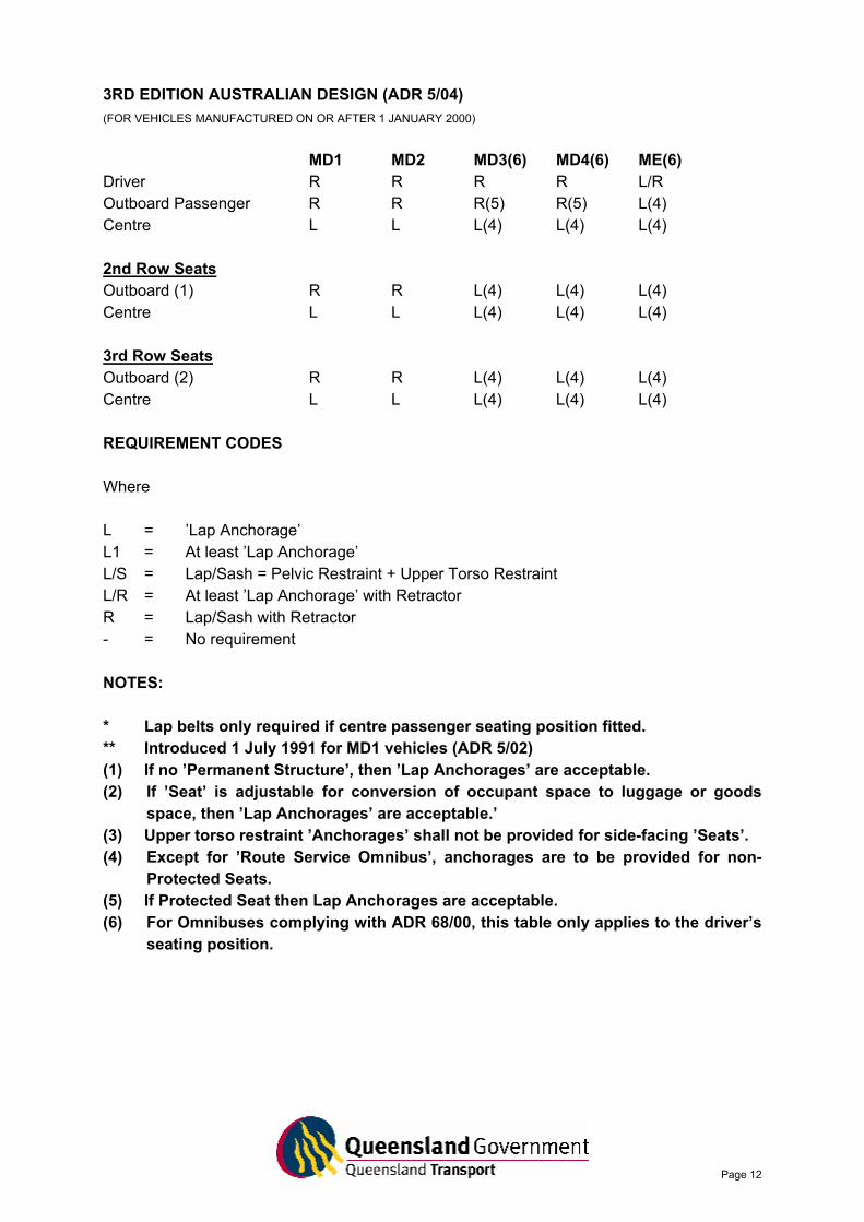
3RD EDITION AUSTRALIAN DESIGN (ADR 5/04) (FOR VEHICLES MANUFACTURED ON OR AFTER 1 JANUARY 2000)
MD1 MD2 MD3(6) MD4(6) ME(6)
Driver R R R R L/R Outboard Passenger R R R(5) R(5) L(4) Centre L L L(4) L(4) L(4) 2nd Row Seats Outboard (1) R R L(4) L(4) L(4) Centre L L L(4) L(4) L(4) 3rd Row Seats Outboard (2) R R L(4) L(4) L(4) Centre L L L(4) L(4) L(4) REQUIREMENT CODES Where L = ’Lap Anchorage’ L1 = At least ’Lap Anchorage’ L/S = Lap/Sash = Pelvic Restraint + Upper Torso Restraint L/R = At least ’Lap Anchorage’ with Retractor R = Lap/Sash with Retractor - = No requirement NOTES: * Lap belts only required if centre passenger seating position fitted. ** Introduced 1 July 1991 for MD1 vehicles (ADR 5/02) (1) If no ’Permanent Structure’, then ’Lap Anchorages’ are acceptable. (2) If ’Seat’ is adjustable for conversion of occupant space to luggage or goods
space, then ’Lap Anchorages’ are acceptable.’ (3) Upper torso restraint ’Anchorages’ shall not be provided for side-facing ’Seats’. (4) Except for ’Route Service Omnibus’, anchorages are to be provided for non-
Protected Seats. (5) If Protected Seat then Lap Anchorages are acceptable. (6) For Omnibuses complying with ADR 68/00, this table only applies to the driver’s
seating position.
Page 13
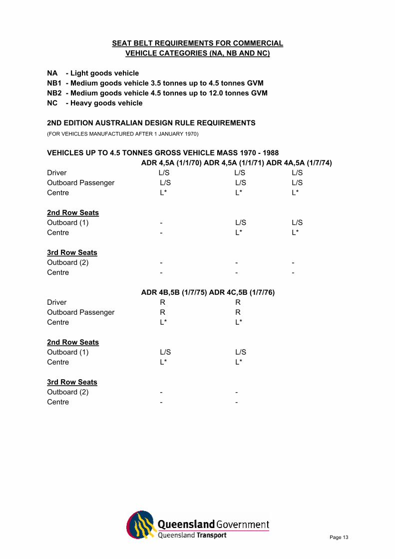
SEAT BELT REQUIREMENTS FOR COMMERCIAL VEHICLE CATEGORIES (NA, NB AND NC)
NA - Light goods vehicle NB1 - Medium goods vehicle 3.5 tonnes up to 4.5 tonnes GVM NB2 - Medium goods vehicle 4.5 tonnes up to 12.0 tonnes GVM NC - Heavy goods vehicle 2ND EDITION AUSTRALIAN DESIGN RULE REQUIREMENTS (FOR VEHICLES MANUFACTURED AFTER 1 JANUARY 1970)
VEHICLES UP TO 4.5 TONNES GROSS VEHICLE MASS 1970 - 1988
ADR 4,5A (1/1/70) ADR 4,5A (1/1/71) ADR 4A,5A (1/7/74) Driver L/S L/S L/S Outboard Passenger L/S L/S L/S Centre L* L* L* 2nd Row Seats Outboard (1) - L/S L/S Centre - L* L* 3rd Row Seats Outboard (2) - - - Centre - - -
ADR 4B,5B (1/7/75) ADR 4C,5B (1/7/76) Driver R R Outboard Passenger R R Centre L* L* 2nd Row Seats Outboard (1) L/S L/S Centre L* L* 3rd Row Seats Outboard (2) - - Centre - -
Page 14
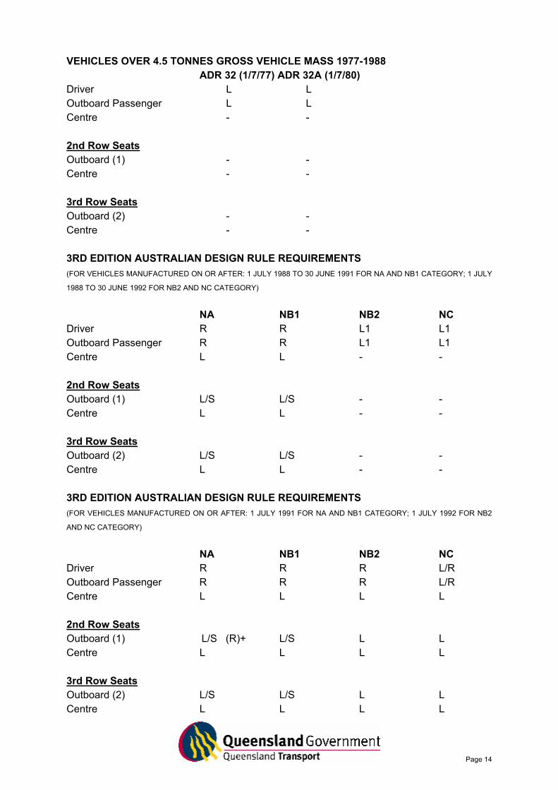
VEHICLES OVER 4.5 TONNES GROSS VEHICLE MASS 1977-1988 ADR 32 (1/7/77) ADR 32A (1/7/80)
Driver L L Outboard Passenger L L Centre - - 2nd Row Seats Outboard (1) - - Centre - - 3rd Row Seats Outboard (2) - - Centre - - 3RD EDITION AUSTRALIAN DESIGN RULE REQUIREMENTS (FOR VEHICLES MANUFACTURED ON OR AFTER: 1 JULY 1988 TO 30 JUNE 1991 FOR NA AND NB1 CATEGORY; 1 JULY
1988 TO 30 JUNE 1992 FOR NB2 AND NC CATEGORY)
NA NB1 NB2 NC
Driver R R L1 L1 Outboard Passenger R R L1 L1 Centre L L - - 2nd Row Seats Outboard (1) L/S L/S - - Centre L L - - 3rd Row Seats Outboard (2) L/S L/S - - Centre L L - - 3RD EDITION AUSTRALIAN DESIGN RULE REQUIREMENTS (FOR VEHICLES MANUFACTURED ON OR AFTER: 1 JULY 1991 FOR NA AND NB1 CATEGORY; 1 JULY 1992 FOR NB2
AND NC CATEGORY)
NA NB1 NB2 NC
Driver R R R L/R Outboard Passenger R R R L/R Centre L L L L 2nd Row Seats Outboard (1) L/S (R)+ L/S L L Centre L L L L 3rd Row Seats Outboard (2) L/S L/S L L Centre L L L L
Page 15
+ = Manufactured after 1 July 1996 for NA category vehicles. REQUIREMENT CODES Where: L = ’Lap Anchorage’ L1 = At least ’Lap Anchorage’ L/S = Lap/Sash = Pelvic Restraint + Upper Torso Restraint L/R = At least ’Lap Anchorage’ with Retractor R = Lap/Sash with Retractor - = No requirement NOTES: * Lap belts only required if centre passenger seating position fitted. (1) If no ’Permanent Structure’, then ’Lap Anchorages’ are acceptable. (2) If ’Seat’ is adjustable for conversion of occupant space to luggage or goods
space, then ’Lap Anchorages’ are acceptable.
Page 16
AIS INFORMATION SHEET No. 3
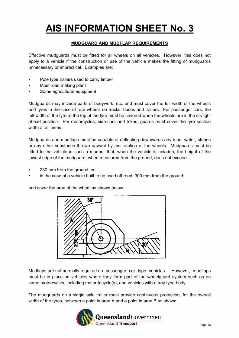
MUDGUARD AND MUDFLAP REQUIREMENTS Effective mudguards must be fitted for all wheels on all vehicles. However, this does not apply to a vehicle if the construction or use of the vehicle makes the fitting of mudguards unnecessary or impractical. Examples are: • Pole type trailers used to carry timber • Most road making plant • Some agricultural equipment Mudguards may include parts of bodywork, etc. and must cover the full width of the wheels and tyres in the case of rear wheels on trucks, buses and trailers. For passenger cars, the full width of the tyre at the top of the tyre must be covered when the wheels are in the straight ahead position. For motorcycles, side-cars and trikes, guards must cover the tyre section width at all times. Mudguards and mudflaps must be capable of deflecting downwards any mud, water, stones or any other substance thrown upward by the rotation of the wheels. Mudguards must be fitted to the vehicle in such a manner that, when the vehicle is unladen, the height of the lowest edge of the mudguard, when measured from the ground, does not exceed: • 230 mm from the ground; or • in the case of a vehicle built to be used off road, 300 mm from the ground; and cover the area of the wheel as shown below.
Mudflaps are not normally required on passenger car type vehicles. However, mudflaps must be in place on vehicles where they form part of the wheelguard system such as on some motorcycles, including motor tricycle(s), and vehicles with a tray type body. The mudguards on a single axle trailer must provide continuous protection, for the overall width of the tyres, between a point in area A and a point in area B as shown.

Page 17
Where 2 or more axles are fitted, separate guards for each wheel or a single guard which provides the required protection over all the wheels may be fitted. Mudflaps must be manufactured from a malleable material which is able to maintain its shape under duress.
Page 18
AIS INFORMATION SHEET No. 4 HEADLIGHT TESTING SCREENS
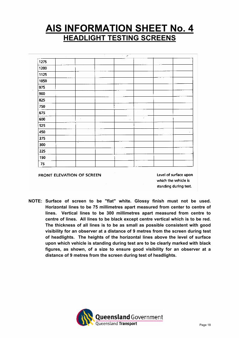
NOTE: Surface of screen to be "flat" white. Glossy finish must not be used.
Horizontal lines to be 75 millimetres apart measured from center to centre of lines. Vertical lines to be 300 millimetres apart measured from centre to centre of lines. All lines to be black except centre vertical which is to be red. The thickness of all lines is to be as small as possible consistent with good visibility for an observer at a distance of 9 metres from the screen during test of headlights. The heights of the horizontal lines above the level of surface upon which vehicle is standing during test are to be clearly marked with black figures, as shown, of a size to ensure good visibility for an observer at a distance of 9 metres from the screen during test of headlights.
Page 19
AIS INFORMATION SHEET No. 5
MISSING COMPLIANCE PLATES For the purposes of registration, all motor vehicles originally manufactured to comply with the Australian Design Rules (ADR’s) on or after 1 January 1972 and motorcycles constructed after 1 July 1975 would have been fitted with a compliance plate. Vehicles built prior to this date must comply with the Transport Operations (Road Use Management - Vehicle Standards and Safety) Regulation 1999. Vehicles assembled for the Australian market (locally built and/or imported vehicles manufactured to comply with the ADR’s. e.g. Holden, Ford, Mazda, Suzuki, Mercedes Benz, BMW etc. If inspecting a motor vehicle or motorcycle manufactured after these dates (not including other individually imported vehicles) which does not have a compliance plate fitted, the proprietor/nominee should:
• ask for proof that the vehicle was previously registered in Queensland, i.e. current registration certificate or copy of previous registration certificate;
OR
• if an interstate registration, proof that the vehicle was previously registered in another state or territory. (Note: if the vehicle has been modified, follow procedures outlined in the Modification Section of the Vehicle Inspection Guidelines);
OR
• advise the owner that it may be possible to obtain a letter of compliance from the vehicle manufacturer confirming the vehicle was manufactured for the Australian market and met all applicable ADR's at the time of manufacture.
Where the owner of the vehicle is unable to provide any documentation, he/she should be advised to obtain a modification plate and certificate of modification issued by an Approved Person. Where applicable, Queensland Transport will consider issuing a permit exempting the vehicle from the need to fit a compliance plate. In most instances, vehicles (except motorcycles) built prior to 1 January 1972 will be fitted with a manufacturer’s identification plate. Other Imported vehicles Vehicles imported into Australia after 1 August 1989 are eligible for the issue of a Safety Certificate or Certificate of Inspection where:
Page 20
• a personal import (yellow) compliance plate and a Queensland Transport modification plate with Code L03; or
• a low volume (green) compliance plate is fitted.
Vehicles imported prior to 1 August 1989: Vehicles which were imported into Australia prior to 1 August 1989 will be eligible for a safety Certificate or Certificate of Inspection on the condition that the owner can provide:
• proof of previous registration in Queensland prior to 1 August 1989; or
• proof of previous registration in another state/territory prior to 1 August 1989; or
• a permit from Queensland Transport, exempting the vehicle from the need to fit a compliance plate as was required in the previous Queensland Traffic Regulations and superceded by the Transport Operations (Road Use Management - Vehicle Standards and Safety) Regulation 1999, is provided.
Please Note: Vehicles imported into Australia on or after 1 August 1989 which are more than 15 years old are exempt from the provisions of the Federal Motor Vehicles Standards Act and do not require a Compliance Plate to satisfy Queensland Transport registration requirements. These vehicles, if built on or after 1 January 1972, must be fitted with either of the following:
• a modification plate endorsed with either LO1 or LO3; and
• in the case of LO3 endorsement, a permit issued by Queensland Transport. Imported vehicles built on or before 31 December 1971 must comply with the Transport Operations (Road Use Management – Vehicle Standards and Safety) Regulation 1999. An Approved Person may issue a modification plate confirming this under Code L02 of the Code of Practice - Light Motor Vehicles.
Page 21
AIS INFORMATION SHEET No. 6
LIQUEFIED PETROLEUM GAS (LPG) AND COMPRESSED NATURAL GAS (CNG) CERTIFICATION As a result of a number of enquiries regarding LPG and CNG installations in motor vehicles when presented for a Safety Certificate or a Certification of Inspection at an Approved Inspection Station, current inspection procedures have been revised in order to clarify the required procedures. The following details are provided to give approved examiners clear guidance as to inspection requirements. Regulation 99 of the Gas Regulations 1989 requires that: The appliances, containers and other fittings and systems installed in all motor vehicles, caravans and vessels shall be inspected within one month prior to delivery of possession to any person pursuant to any sale or other transfer of ownership. NOTE: With the Safety Certificate now having a life of up to three (3) months and to ensure
that certificates have the same life and to avoid confusion, the Chief Gas Examiner has approved, subject to Regulation 122 of the Gas Regulation 1989, that certificates prepared for the sale or other transfer of possession shall apply for a period of one month or for the period of the Queensland Transport Safety Certificate, whichever is the longer.
There is also a requirement under the Gas Regulations 1989 that motor vehicles and caravans which are used for carrying passengers, or goods, or both passengers and goods for hire and reward, or in the course of or for any purposes of any business or work, to have the LPG or CNG installation inspected at least once in every period of twelve months and a certificate of compliance issued. There is currently no legislation requiring vehicles fitted with LPG or CNG and used solely for private use to have a periodic inspection but the owner of a motor vehicle or caravan must ensure all fittings in the caravan or vehicle are maintained in a safe and efficient condition. Due to the complexity of determining for what purpose a vehicle is specifically used, the following policy will apply to vehicles inspected for the issue of a Safety Certificate or a Certificate of Inspection:
• A gas certificate will not be required to be produced or sighted for the issue of a Safety Certificate or a Certificate of Inspection of any vehicle.
Page 22
NOTE: If during the course of an inspection of the vehicle, any obvious or dangerous defects are observed with the LPG or CNG installation, the vehicle is to be rejected and the reason recorded in the space provided. However, the owner of any motor vehicle or caravan is to be advised that if LPG or CNG appliances are fitted, a gas certificate issued within the prior 30 days or for the period of the Queensland Transport Safety Certificate, whichever is the longer, will be required at the time of vehicle registration or transfer. Any gas installation in a vehicle must have the installation and any subsequent alterations certified by a licensed gas installer.
Page 23
AIS INFORMATION SHEET No. 7
BRAIDED BRAKE HOSES
Queensland Transport has approved a number of brands of stainless steel brake hose assemblies that comply with Australian Design Rule 7/00 (Hydraulic Brake Hoses). The braided brake hose assemblies may be utilised on both motor cars and motor cycles. Details of approved stainless steel brake hose assemblies are as follows: RUSSELL PERFORMANCE PRODUCTS This hose is manufactured by Russell Performance Products and each hose must be identified with the brand name RUSSELL permanently printed on a teflon sleeve which must be permanently fitted to the hose assembly. A stencilled label on the braided section of the hose also carries the following information: TITEFLEX DOT 1/8*HL 1194 111125-701D * This dimension may vary. NOTE: The stencilled label information must be evident on all new products but is not required to be permanently labelled to the hose assembly. Specialised banjo fittings are supplied to enable the adoption of universal hose assemblies that are supplied in the hose kit and are not identified. GOODRIDGE This hose is manufactured by Goodridge Ltd and the following identification details must be embossed on the line nipple: GOODRIDGE (Company Name) TYPE 1 (Type of hose) MONTH and YEAR of MANUFACTURE The external diameter of the hose is 5.0 mm (excluding protective sheath), 6.3mm (1/4 inch) with sheath and an internal diameter of 3.2 mm (1/8 inch). PACIFIC HOSE FLEX This hose is manufactured by Pacific Hose Flex (Burleigh Heads, Qld). The brake hose assemblies are designed with a teflon lined inner tube and stainless steel outer braid. The assemblies are equipped with crimped tail fittings and rubber wear protections (marked NBM) at the coupling sleeves. A Pacific Hose Flex stencilled label is attached to the outer hose assembly with test and date provisions included on the label.
Page 24
NOTE: The stencilled label information must be evident on all new products but is not required to be permanently labelled to the hose assembly. The external diameter of the hose is approximately 6.0 mm (excluding protective sheath) and an internal diameter (nominal bore) of 3.2mm (1/8 inch). BRAKEQUIP This hose is manufactured by BrakeQuip Australia of 49 John Street Oakleigh Victoria 3166. The BrakeQuip Stainless Steel Braided Brake Hose assemblies consist of stainless steel braided hose that is crimped to a BrakeQuip fitting with the insertion of a specially formulated 'insert'. The brake hose assemblies are constructed of an extruded teflon tube with a stainless steel single wire braid cover. The external diameter of the hose is approximately 6.4 mm (1/4 inch) and an internal diameter (nominal bore) of 3.2mm (1/8 inch). Labelling with the following details will be attached to the insert: BrakeQuip ADR 7/00 CRN:xxxxx CRN is an abbreviation for Component Reference Number. When this number is allocated, the number will replace the xxxxx. These hoses are suitable for brake and clutch hoses, instrument hoses, fuel injection nozzle hoses, turbo-charger oil feed and boost hoses and any application subjected to high temperatures. . NOTE: The stencilled label information must be evident on all new products but is not required to be permanently labelled to the hose assembly. Licenced Examiners Action: If, during the course of an inspection, Licenced Examiners have cause to inspect vehicles modified by the fitting of braided brake hose assemblies, they are to ensure that individual hoses comply with the previously mentioned details. Hoses that do not comply should be rejected immediately.
Page 25
AIS INFORMATION SHEET No. 8
MOTOR VEHICLE LIGHTING Introduction Motor vehicle lighting plays an important part in vehicle and road safety. Lighting is particularly important in poor visibility circumstances (such as rain or fog) and at night. Motor vehicle lighting impacts on road safety in two ways:
• it assists the driver’s vision by lighting the road surface and surrounding objects; • it allows other road users to see a vehicle on the road (tail lights, head lights, park
lights, stop lights and indicators). This attachment is about those aspects of motor vehicle lighting that can be checked, and, in many instances, rectified. What can be checked Motor vehicle lighting defects can occur at any time and unless regular safety checks are made, owners may not be aware of a problem. Lighting can be easily checked when washing or cleaning a motor vehicle, particularly if assistance is available. These types of checks should be conducted regularly to ensure the vehicle’s lights comply with the minimum safety standards at all times. Lights that can be checked include: HEADLIGHTS
• for effective high or low beam operation; • for discolouration or imbalance in light when switched on; • for peeling, tarnishing or deterioration of the reflecting surface; • for cracks or other damage to lenses.
TURN SIGNAL INDICATORS (trafficators, blinkers)
• for effective operation (including self cancelling where it applies); • for an audible/visible indicator to indicate the signals are operating effectively; • for excessive discolouration, fading, cracks or other damage to the lenses.
Page 26
BRAKE LIGHTS (including eye level brake lamps)
• for effective operation when the foot brake is applied; • for appropriate difference in light intensity when compared with the tail lights in the
"on" position; • for excessive discolouration of fading of the red lenses; • for cracks or other damage to the lenses.
REVERSING LIGHTS
• for effective lighting when reverse gear is engaged (ensure either the ignition "on" or the engine running);
• for switching off when reverse gear is disengaged; • for discolouration, cracks or damage to the lenses.
NUMBER PLATE LIGHT/S (rear only)
• for effective operation when headlights or tail/park lights are switched on. A total failure of one or more lighting components (e.g. headlights or brake lights) may signify a blown fuse. Many motorists carry a spare fuse kit in their motor vehicle to avoid inconvenience in such circumstances. Repair of Lighting Defects Most lighting defects can be corrected by replacing the damaged bulb, filament, fuse or lens. Care should be taken to ensure that any replacement is of equivalent candle power to that specified by the motor vehicle manufacturer. When a lens is to be replaced, the replacement lens must conform to the original manufacturer’s colour specifications. If the defect occurs after repair, the circuit should be checked by an appropriately qualified tradesperson. REMEMBER
• Lighting defects may seriously impair a driver’s ability to see clearly and the ability of other road users to see a motor vehicle with defective lighting.
• A motor vehicle owner is legally responsible for ensuring the vehicle complies with the
minimum safety standard at all times.
• Drivers also are responsible for the condition of the motor vehicle they drive.
Page 27
AIS INFORMATION SHEET No. 9
REAR MARKER PLATES Introduction Retro-reflective rear marker plates are required for all vehicles with a Gross Vehicle Mass (GVM) of 12 tonnes or more. This requirement also applies to trailers which are hauled by trucks or prime movers with a Gross Combination Mass (GCM) of 12 tonnes or more. Prime mover and semi trailer combinations must display the plates at the rear of the semi-trailer. When a prime mover is used without a semi-trailer, marking plates must be fitted to the rear of the prime mover. Route service buses used solely in urban areas are exempt from these requirements. Implementation There have been difficulties in the past with the installation and durability of heavy vehicle rear marker plates. Because of these difficulties, Australian Standards AS 4001 – 1992 Motor Vehicles – Rear Marker Plates Part 1 (Manufacturing requirements) and Part 2 (Fitting requirements) have been revised to include the new style of plates made from Class 1 retro-reflective material. Class 1 retro-reflective material is more durable and because of its improved retro-reflective performance, when compared to the older Class 2 plates, the plates can be smaller and yet reflect more light. Australian Design Rule 13/00 has been amended to permit the use of the new style plates on new vehicles. Manufacturers are now able to use either style provided that both plates on any one vehicle must be of the same size and material. Plates complying with AS 4001 are available in either rectangular or strip configuration as illustrated in the Figures 1 and 2 respectively. Note: The installation dimensions and plate size requirements of the revised Australian Standard differ from those originally shown in previous information bulletins. The information in this attachment is a relaxation on previous plate size and locational requirements. Retro-reflective material Class 1 and 2 plates must be fitted with retro-reflective material which meets Australian Standards AS 1906 Class 1 or Class 2. Amended Design and Installation Requirements for Class 1 Plates Dimensions and graphics of the Class 1 Rear Marking plates are shown in the following diagrams.
Page 28
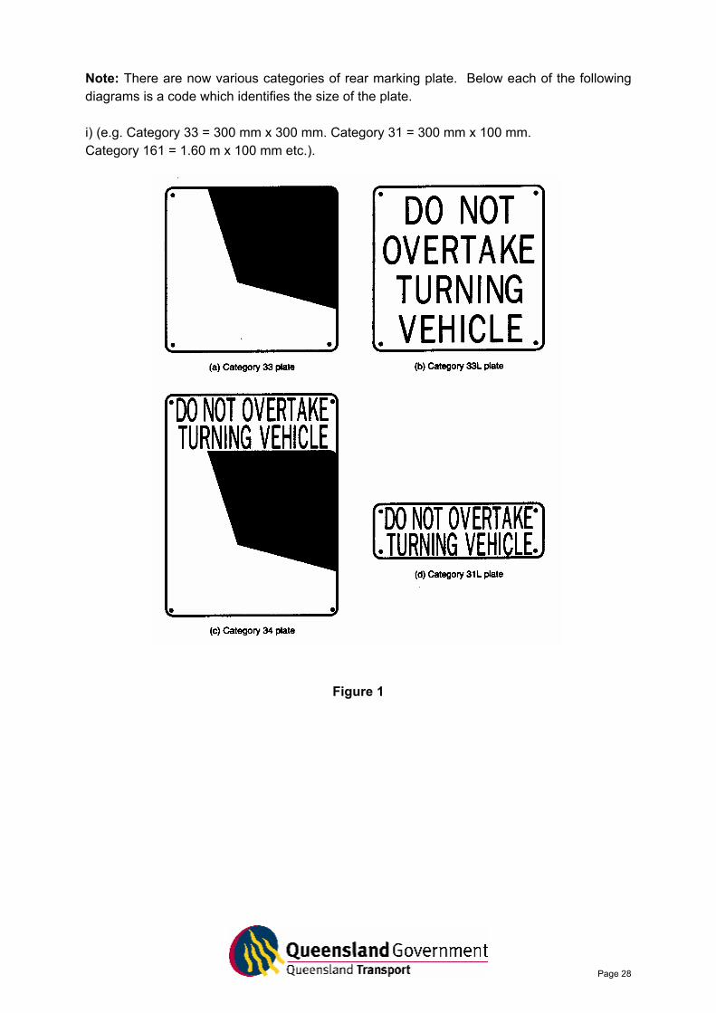
Note: There are now various categories of rear marking plate. Below each of the following diagrams is a code which identifies the size of the plate. i) (e.g. Category 33 = 300 mm x 300 mm. Category 31 = 300 mm x 100 mm. Category 161 = 1.60 m x 100 mm etc.).
Figure 1
Page 29
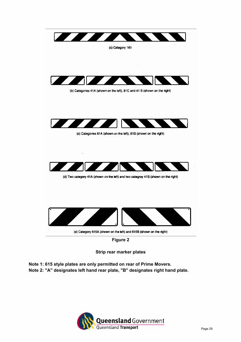
Figure 2
Strip rear marker plates Note 1: 615 style plates are only permitted on rear of Prime Movers. Note 2: "A" designates left hand rear plate, "B" designates right hand plate.
Page 30
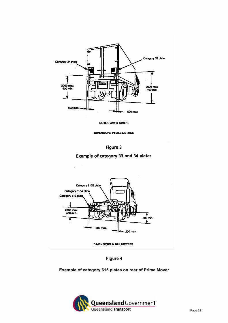
Installed Orientation, Configuration and Position Orientation When installed on a vehicle, rear marker plates shall be at a height above the road surface and at a distance in from the outer edge of the vehicle as specified in the Table 1. When installed on a vehicle, the colour bands of the plate must slope down and outwards (away from the centre of the vehicle). The minimum configuration for rear marker plates when fitted to a vehicle shall be one of the following. Configuration The minimum configuration for rear marker plates when fitted to a vehicle shall be one of the following: i) Category 34 (Not permitted for vehicles with an overall length less than 7.5 metres). A
category 34 plate shall be located on the rear, near vertical surface of the vehicle at the left hand side in conjunction with a category 33 plate located at the right hand side. Both plates should be positioned symmetrically about the longitudinal centerline of the vehicle and at the same height to the bottom of each plate, as shown in Figure 3.
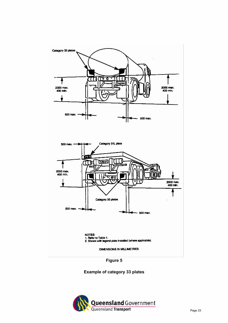
ii) Category 33 plates should be located on the rear, near vertical surface of the vehicle.
Both plates should be positioned symmetrically about the longitudinal centerline of the vehicle and at the same height to the bottom of each plate, as shown in Figure 5.
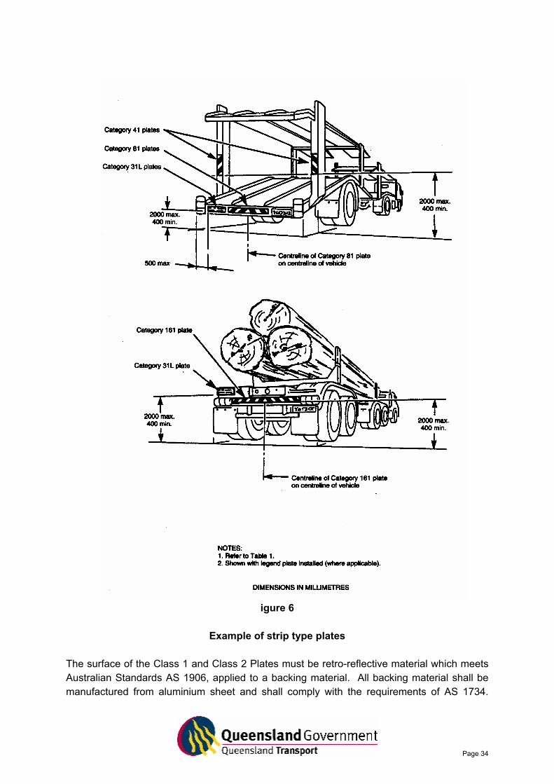
It is recommended that, for vehicles of length 7.5 metres or over, a category 31L or 33L plate also be located on this surface at the left side of the vehicle above the category 33 plate. iii) Categories 41, 81 and 161. Where space limitations prevent the use of either of the
above two configurations, 100 mm strip plates shall be used, other than on prime movers. Category 41, 81 and 161 plates should be located on the rear, near vertical surface of the vehicle symmetrically about the longitudinal centerline. These plates can be installed horizontally or vertically, but their configured pattern should be symmetrical about the longitudinal centerline of the vehicle. The total of strip plate area shall not be less than 0.16 sq metre.
It is recommended that, for vehicles of length 7.5 metres or over, a category 31L or 33L plate also be located on the rear, near vertical surface at the left hand side of the rear of the vehicle. Examples of installed configurations of strip plates are given in Figure 6. iv) Category 615. Prime movers shall be fitted with a pair or category 615 plates, or with
one of the alternative configurations above (see items i) or ii)). These shall be installed on a near vertical surface (e.g. mud flaps) at the rear of the vehicle and should be positioned at the same height.
It is recommended that a category 31L plate also be located on the left hand side of the rear of the vehicle above the category 615 plate (see Figure 4).
Page 31
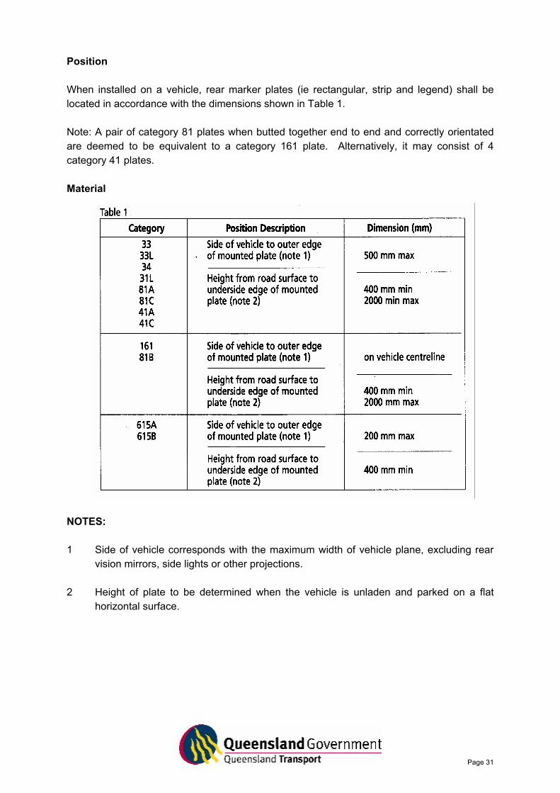
Position When installed on a vehicle, rear marker plates (ie rectangular, strip and legend) shall be located in accordance with the dimensions shown in Table 1. Note: A pair of category 81 plates when butted together end to end and correctly orientated are deemed to be equivalent to a category 161 plate. Alternatively, it may consist of 4 category 41 plates. Material
NOTES: 1 Side of vehicle corresponds with the maximum width of vehicle plane, excluding rear
vision mirrors, side lights or other projections. 2 Height of plate to be determined when the vehicle is unladen and parked on a flat
horizontal surface.
Page 32
Figure 4
Example of category 615 plates on rear of Prime Mover
Page 33
Figure 5
Example of category 33 plates
Page 34
igure 6
Example of strip type plates The surface of the Class 1 and Class 2 Plates must be retro-reflective material which meets Australian Standards AS 1906, applied to a backing material. All backing material shall be manufactured from aluminium sheet and shall comply with the requirements of AS 1734.
Page 35
The retro-reflective material must be applied to the required backing material. Application directly to a vehicle is not permitted. Marking The front retro-reflective face of each plate must be marked in either red or black lettering, with the name of the manufacturer or his agent in letters and numbers not greater than 3 mm in height. The manufacturer’s telephone number is optional if manufactured in Australia. Plates must also clearly display letters indicating the correct orientation on the vehicle. Installation Methods The bending of Rear Marker Plates is not permitted. Plates should not be cut by the installer, only by the manufacturer or agent. However, if cutting is unavoidable, the resultant gap between section of the plate shall not exceed 10 mm after installation. It is preferable to consider the use of an alternative category plate before cutting. Plates should be installed vertically to give optimum performance. It is the responsibility of the vehicle operator to ensure the plates are kept clean. Faded or damaged plates should be replaced.
Page 36
AIS INFORMATION SHEET No. 10
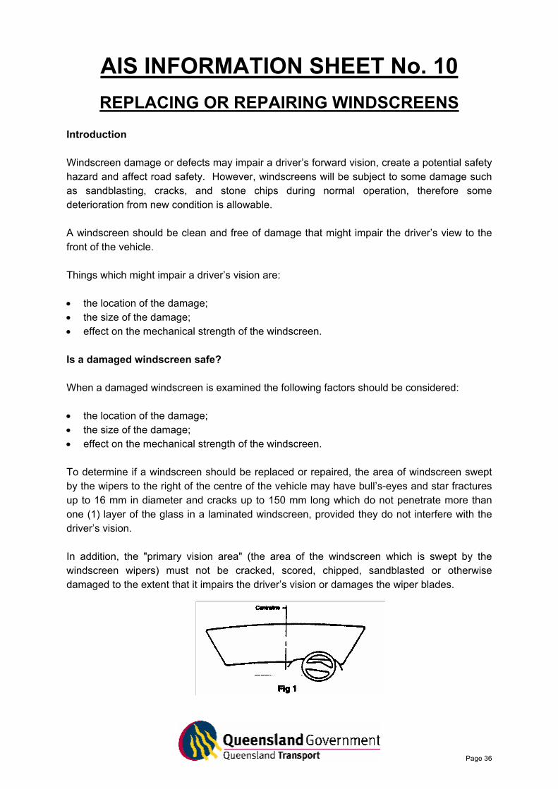
REPLACING OR REPAIRING WINDSCREENS Introduction Windscreen damage or defects may impair a driver’s forward vision, create a potential safety hazard and affect road safety. However, windscreens will be subject to some damage such as sandblasting, cracks, and stone chips during normal operation, therefore some deterioration from new condition is allowable. A windscreen should be clean and free of damage that might impair the driver’s view to the front of the vehicle. Things which might impair a driver’s vision are: • the location of the damage; • the size of the damage; • effect on the mechanical strength of the windscreen. Is a damaged windscreen safe? When a damaged windscreen is examined the following factors should be considered: • the location of the damage; • the size of the damage; • effect on the mechanical strength of the windscreen. To determine if a windscreen should be replaced or repaired, the area of windscreen swept by the wipers to the right of the centre of the vehicle may have bull’s-eyes and star fractures up to 16 mm in diameter and cracks up to 150 mm long which do not penetrate more than one (1) layer of the glass in a laminated windscreen, provided they do not interfere with the driver’s vision. In addition, the "primary vision area" (the area of the windscreen which is swept by the windscreen wipers) must not be cracked, scored, chipped, sandblasted or otherwise damaged to the extent that it impairs the driver’s vision or damages the wiper blades.

Page 37
It is recommended that all defects be repaired as soon as possible. Repairing windscreen damage Repairing a damaged windscreen, if undertaken correctly, is an acceptable means of reinstating a windscreen to a safe condition. Repaired windscreens must comply with the following requirements: • when inspected from the inside of the vehicle, the repair should not exhibit any significant
optical defects which would distort or distract the vision of the driver and should restore clarity to the damaged area. (Acceptable limits of repairs are outlined in Note 1);
• any repair to the windscreen should not reduce the effectiveness of the windscreen
wipers; • windscreen repair material must be used in accordance with the manufacturer’s
instructions. If a repair has been unsuccessful or is unlikely to be effective, the vehicle owner is responsible for replacing the windscreen in order to meet the necessary safety requirements. NOTE 1 In a repaired windscreen, a faint outline of the repair, or in some cases, a slight dull spot may be visible where the repair has been performed. A repaired crack may also be detectable by a fine hairline surface mark. These are acceptable and should not cause a vehicle to fail a safety inspection provided the damaged windscreen has been repaired to a standard which complies with the requirements outlined in this document. To date, the extent of windscreen damage considered to be repairable has not been defined. Improved technology has increased the scope of repairable damage and acceptability can only be determined (in accord with the above standards) after the repair has been completed. It is recommended that repairs of cracks longer than 350 mm be avoided. NOTE 2 The Australian Standard AS 2366-1990 (Repair of Laminated Glass Windscreens Fitted to Road Vehicles) is a voluntary code of practice for the repair of automotive windscreens that gives recommended practices regarding the repair of laminated windscreens. The use of the Australian Standard is not mandatory.
Page 38
Replacement windscreens To ensure the safety of all motor vehicle occupants, replacement windscreens must be of an approved safety glass.
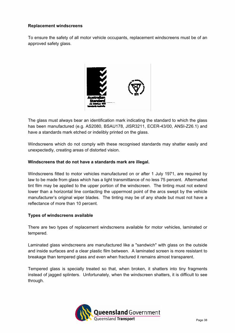
The glass must always bear an identification mark indicating the standard to which the glass has been manufactured (e.g. AS2080, BSAU178, JISR3211, ECER-43/00, ANSI-Z26.1) and have a standards mark etched or indelibly printed on the glass. Windscreens which do not comply with these recognised standards may shatter easily and unexpectedly, creating areas of distorted vision. Windscreens that do not have a standards mark are illegal. Windscreens fitted to motor vehicles manufactured on or after 1 July 1971, are required by law to be made from glass which has a light transmittance of no less 75 percent. Aftermarket tint film may be applied to the upper portion of the windscreen. The tinting must not extend lower than a horizontal line contacting the uppermost point of the arcs swept by the vehicle manufacturer’s original wiper blades. The tinting may be of any shade but must not have a reflectance of more than 10 percent. Types of windscreens available There are two types of replacement windscreens available for motor vehicles, laminated or tempered. Laminated glass windscreens are manufactured like a "sandwich" with glass on the outside and inside surfaces and a clear plastic film between. A laminated screen is more resistant to breakage than tempered glass and even when fractured it remains almost transparent. Tempered glass is specially treated so that, when broken, it shatters into tiny fragments instead of jagged splinters. Unfortunately, when the windscreen shatters, it is difficult to see through.
Page 39
Vehicles manufactured on or after 1 January 1994 must be fitted with laminated glass windscreens. Whilst vehicles built before 1 January 1994 do not have to meet this requirement, it is strongly recommended that when a replacement windscreen is needed, laminated glass be used. Remember • Windscreen damage or defects could seriously impair a driver’s ability to see clearly,
thereby presenting a safety hazard. • The owner of a motor vehicle is legally responsible for ensuring that his/her vehicle
complies with relevant safety standards. • Drivers are responsible for the condition of the motor vehicle they drive.
Page 40
AIS INFORMATION SHEET No. 11
RUST AND CORROSION
Introduction This attachment provides simple guidelines for determining if a rust affected motor vehicle is road safe. The average safe operational life of a motor vehicle can be extended by carefully and regularly checking for rust and by repairing rust as soon as possible as it becomes apparent. To determine the safety of a rust affected motor vehicle, this attachment proposes a system of classifying the extent and severity of the rust in relation to the motor vehicle’s structural components. The attachment also provides some information concerning recommended rust repair techniques. Even small deposits of rust can be signs of much more extensive corrosion in a motor vehicle. If rust is repaired when it is minor, it will normally be a simple and economic task. However, rust allowed to spread unchecked (or only partially repaired) can damage a motor vehicle beyond economic repair. Severe rust can be an extreme safety hazard to driver, passenger and other road users. Rust and Motor Vehicle Safety Motor vehicles are carefully designed as rigid structures for normal road use. However, in an accident they are intended to collapse progressively and absorb energy. If the structure of the motor vehicle is weakened by rust, it could lose some of its structural strength and so become unpleasant to drive. More importantly, however, it can lose its energy absorbing capacity and this means that passengers are at greater risk in a collision or accident. Typically, rust develops in enclosed body sections or in areas which can accumulate road deposits, e.g. between body panels, inside door panels, around mudguards or inside the sills just below door level. However, rust can occur on any metallic component of the motor vehicle (including suspension and steering components and the exhaust system). Classification of Rust The extent of corrosion in a motor vehicle can range from light surface rust to the total breakdown of parent metal of a motor vehicle component. The degree to which a component structure is attacked and degraded can vary widely. In general, the formation of rust and resultant loss of metal occurs in areas which retain moisture, because of a build up of road dirt and mud etc. To simplify identification and classification of rust, this attachment classifies the extent of corrosion in three stages.
Page 41
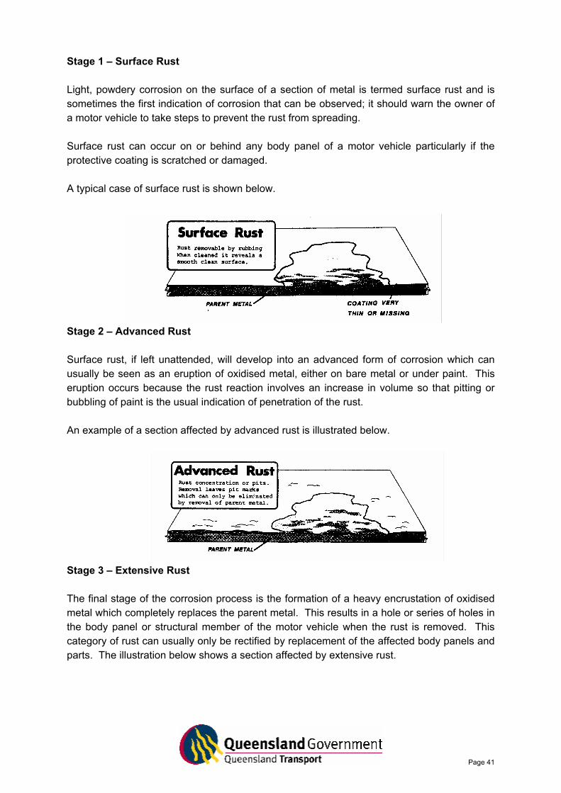
Stage 1 – Surface Rust Light, powdery corrosion on the surface of a section of metal is termed surface rust and is sometimes the first indication of corrosion that can be observed; it should warn the owner of a motor vehicle to take steps to prevent the rust from spreading. Surface rust can occur on or behind any body panel of a motor vehicle particularly if the protective coating is scratched or damaged. A typical case of surface rust is shown below.
Stage 2 – Advanced Rust Surface rust, if left unattended, will develop into an advanced form of corrosion which can usually be seen as an eruption of oxidised metal, either on bare metal or under paint. This eruption occurs because the rust reaction involves an increase in volume so that pitting or bubbling of paint is the usual indication of penetration of the rust. An example of a section affected by advanced rust is illustrated below.
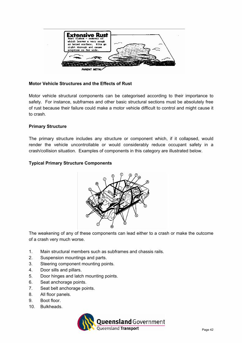
Stage 3 – Extensive Rust The final stage of the corrosion process is the formation of a heavy encrustation of oxidised metal which completely replaces the parent metal. This results in a hole or series of holes in the body panel or structural member of the motor vehicle when the rust is removed. This category of rust can usually only be rectified by replacement of the affected body panels and parts. The illustration below shows a section affected by extensive rust.
Page 42
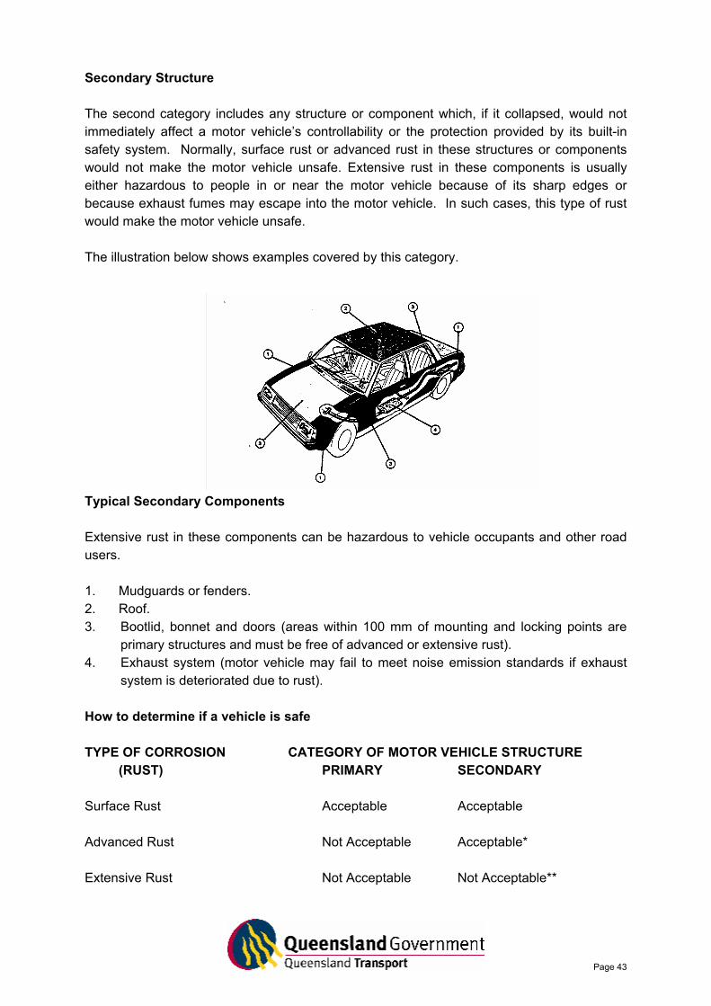
Motor Vehicle Structures and the Effects of Rust Motor vehicle structural components can be categorised according to their importance to safety. For instance, subframes and other basic structural sections must be absolutely free of rust because their failure could make a motor vehicle difficult to control and might cause it to crash. Primary Structure The primary structure includes any structure or component which, if it collapsed, would render the vehicle uncontrollable or would considerably reduce occupant safety in a crash/collision situation. Examples of components in this category are illustrated below. Typical Primary Structure Components
The weakening of any of these components can lead either to a crash or make the outcome of a crash very much worse. 1. Main structural members such as subframes and chassis rails. 2. Suspension mountings and parts. 3. Steering component mounting points. 4. Door sills and pillars. 5. Door hinges and latch mounting points. 6. Seat anchorage points. 7. Seat belt anchorage points. 8. All floor panels. 9. Boot floor. 10. Bulkheads.
Page 43
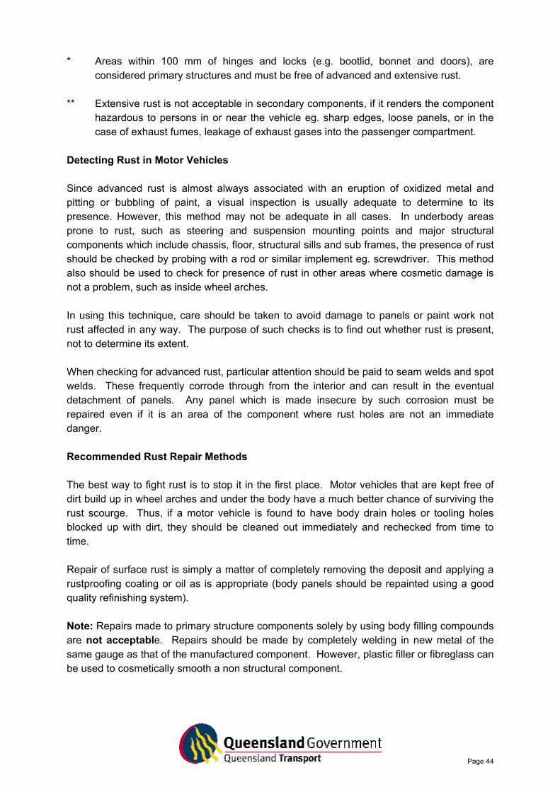
Secondary Structure The second category includes any structure or component which, if it collapsed, would not immediately affect a motor vehicle’s controllability or the protection provided by its built-in safety system. Normally, surface rust or advanced rust in these structures or components would not make the motor vehicle unsafe. Extensive rust in these components is usually either hazardous to people in or near the motor vehicle because of its sharp edges or because exhaust fumes may escape into the motor vehicle. In such cases, this type of rust would make the motor vehicle unsafe. The illustration below shows examples covered by this category.
Typical Secondary Components Extensive rust in these components can be hazardous to vehicle occupants and other road users. 1. Mudguards or fenders. 2. Roof. 3. Bootlid, bonnet and doors (areas within 100 mm of mounting and locking points are
primary structures and must be free of advanced or extensive rust). 4. Exhaust system (motor vehicle may fail to meet noise emission standards if exhaust
system is deteriorated due to rust). How to determine if a vehicle is safe TYPE OF CORROSION CATEGORY OF MOTOR VEHICLE STRUCTURE
(RUST) PRIMARY SECONDARY Surface Rust Acceptable Acceptable Advanced Rust Not Acceptable Acceptable* Extensive Rust Not Acceptable Not Acceptable**
Page 44
* Areas within 100 mm of hinges and locks (e.g. bootlid, bonnet and doors), are considered primary structures and must be free of advanced and extensive rust.
** Extensive rust is not acceptable in secondary components, if it renders the component
hazardous to persons in or near the vehicle eg. sharp edges, loose panels, or in the case of exhaust fumes, leakage of exhaust gases into the passenger compartment.
Detecting Rust in Motor Vehicles Since advanced rust is almost always associated with an eruption of oxidized metal and pitting or bubbling of paint, a visual inspection is usually adequate to determine to its presence. However, this method may not be adequate in all cases. In underbody areas prone to rust, such as steering and suspension mounting points and major structural components which include chassis, floor, structural sills and sub frames, the presence of rust should be checked by probing with a rod or similar implement eg. screwdriver. This method also should be used to check for presence of rust in other areas where cosmetic damage is not a problem, such as inside wheel arches. In using this technique, care should be taken to avoid damage to panels or paint work not rust affected in any way. The purpose of such checks is to find out whether rust is present, not to determine its extent. When checking for advanced rust, particular attention should be paid to seam welds and spot welds. These frequently corrode through from the interior and can result in the eventual detachment of panels. Any panel which is made insecure by such corrosion must be repaired even if it is an area of the component where rust holes are not an immediate danger. Recommended Rust Repair Methods The best way to fight rust is to stop it in the first place. Motor vehicles that are kept free of dirt build up in wheel arches and under the body have a much better chance of surviving the rust scourge. Thus, if a motor vehicle is found to have body drain holes or tooling holes blocked up with dirt, they should be cleaned out immediately and rechecked from time to time. Repair of surface rust is simply a matter of completely removing the deposit and applying a rustproofing coating or oil as is appropriate (body panels should be repainted using a good quality refinishing system). Note: Repairs made to primary structure components solely by using body filling compounds are not acceptable. Repairs should be made by completely welding in new metal of the same gauge as that of the manufactured component. However, plastic filler or fibreglass can be used to cosmetically smooth a non structural component.