Embed Size (px)
Citation preview
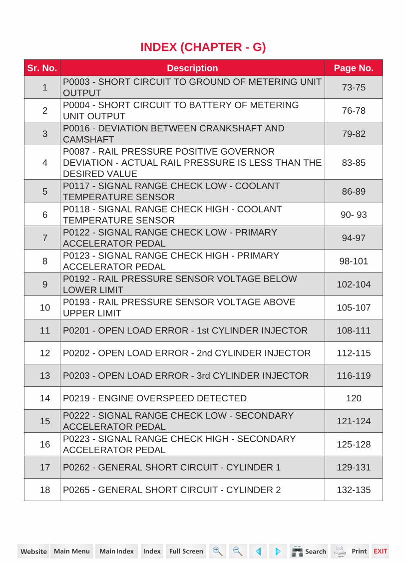
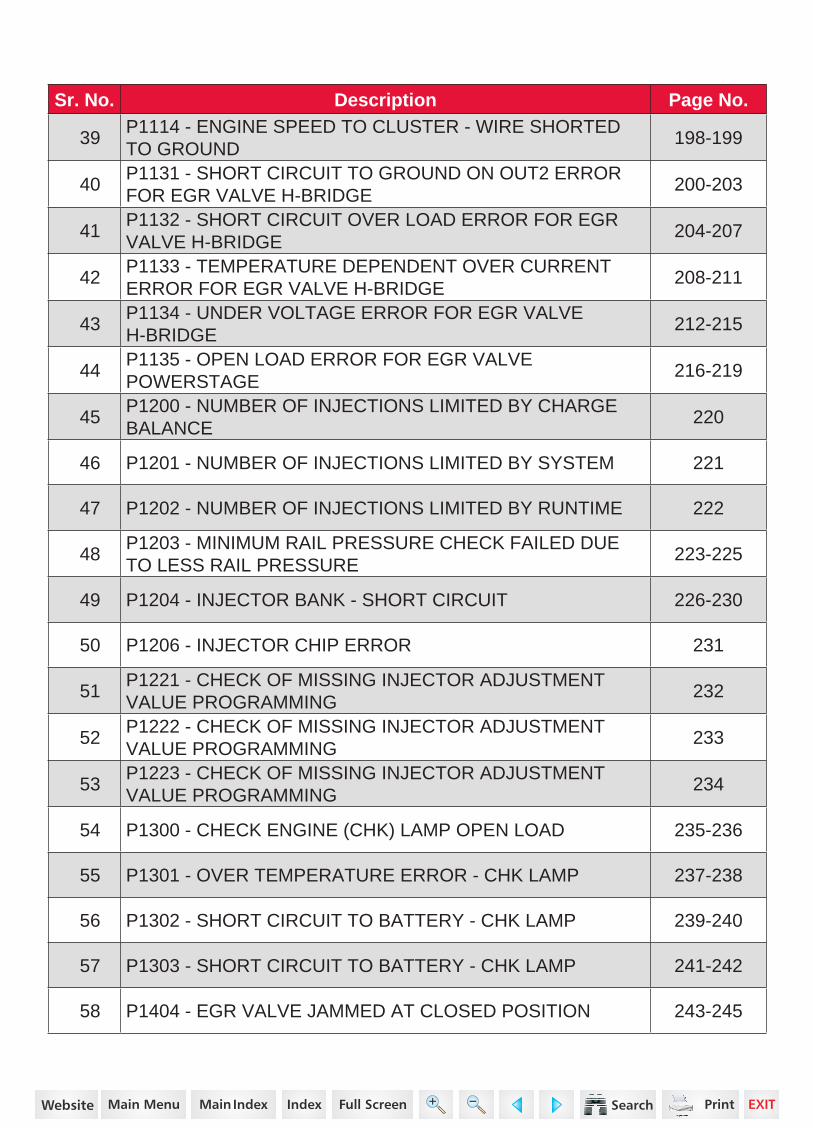
INDEX (CHAPTER - G)
Sr. No. Description Page No.
1P0003 - SHORT CIRCUIT TO GROUND OF METERING UNIT OUTPUT
73-75
2P0004 - SHORT CIRCUIT TO BATTERY OF METERING UNIT OUTPUT
76-78
3P0016 - DEVIATION BETWEEN CRANKSHAFT AND CAMSHAFT
79-82
4P0087 - RAIL PRESSURE POSITIVE GOVERNOR DEVIATION - ACTUAL RAIL PRESSURE IS LESS THAN THE DESIRED VALUE
83-85
5P0117 - SIGNAL RANGE CHECK LOW - COOLANT TEMPERATURE SENSOR
86-89
6P0118 - SIGNAL RANGE CHECK HIGH - COOLANT TEMPERATURE SENSOR
90- 93
7P0122 - SIGNAL RANGE CHECK LOW - PRIMARY ACCELERATOR PEDAL
94-97
8P0123 - SIGNAL RANGE CHECK HIGH - PRIMARY ACCELERATOR PEDAL
98-101
9P0192 - RAIL PRESSURE SENSOR VOLTAGE BELOW LOWER LIMIT
102-104
10P0193 - RAIL PRESSURE SENSOR VOLTAGE ABOVE UPPER LIMIT
105-107
11 P0201 - OPEN LOAD ERROR - 1st CYLINDER INJECTOR 108-111
12 P0202 - OPEN LOAD ERROR - 2nd CYLINDER INJECTOR 112-115
13 P0203 - OPEN LOAD ERROR - 3rd CYLINDER INJECTOR 116-119
14 P0219 - ENGINE OVERSPEED DETECTED 120
15P0222 - SIGNAL RANGE CHECK LOW - SECONDARY ACCELERATOR PEDAL
121-124
16P0223 - SIGNAL RANGE CHECK HIGH - SECONDARY ACCELERATOR PEDAL
125-128
17 P0262 - GENERAL SHORT CIRCUIT - CYLINDER 1 129-131
18 P0265 - GENERAL SHORT CIRCUIT - CYLINDER 2 132-135
https://www.truck-manuals.net/
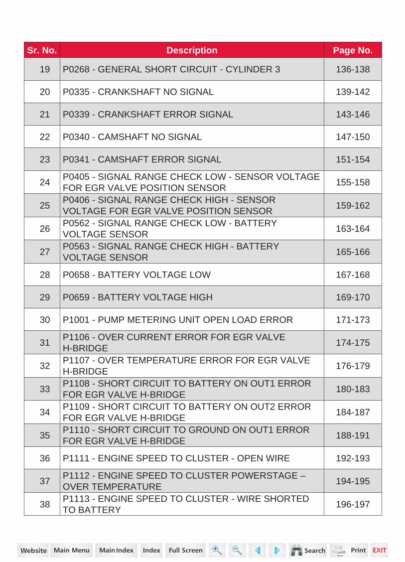
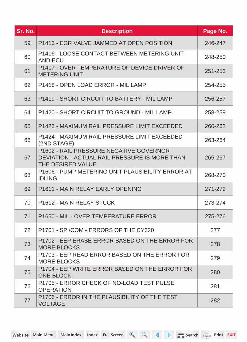
Sr. No. Description Page No.
19 P0268 - GENERAL SHORT CIRCUIT - CYLINDER 3 136-138
20 P0335 - CRANKSHAFT NO SIGNAL 139-142
21 P0339 - CRANKSHAFT ERROR SIGNAL 143-146
22 P0340 - CAMSHAFT NO SIGNAL 147-150
23 P0341 - CAMSHAFT ERROR SIGNAL 151-154
24P0405 - SIGNAL RANGE CHECK LOW - SENSOR VOLTAGE FOR EGR VALVE POSITION SENSOR
155-158
25P0406 - SIGNAL RANGE CHECK HIGH - SENSOR VOLTAGE FOR EGR VALVE POSITION SENSOR
159-162
26P0562 - SIGNAL RANGE CHECK LOW - BATTERY VOLTAGE SENSOR
163-164
27P0563 - SIGNAL RANGE CHECK HIGH - BATTERY VOLTAGE SENSOR
165-166
28 P0658 - BATTERY VOLTAGE LOW 167-168
29 P0659 - BATTERY VOLTAGE HIGH 169-170
30 P1001 - PUMP METERING UNIT OPEN LOAD ERROR 171-173
31P1106 - OVER CURRENT ERROR FOR EGR VALVE H-BRIDGE
174-175
32P1107 - OVER TEMPERATURE ERROR FOR EGR VALVE H-BRIDGE
176-179
33P1108 - SHORT CIRCUIT TO BATTERY ON OUT1 ERROR FOR EGR VALVE H-BRIDGE
180-183
34P1109 - SHORT CIRCUIT TO BATTERY ON OUT2 ERROR FOR EGR VALVE H-BRIDGE
184-187
35P1110 - SHORT CIRCUIT TO GROUND ON OUT1 ERROR FOR EGR VALVE H-BRIDGE
188-191
36 P1111 - ENGINE SPEED TO CLUSTER - OPEN WIRE 192-193
37P1112 - ENGINE SPEED TO CLUSTER POWERSTAGE – OVER TEMPERATURE
194-195
38P1113 - ENGINE SPEED TO CLUSTER - WIRE SHORTED TO BATTERY
196-197
https://www.truck-manuals.net/
Sr. No. Description Page No.
39P1114 - ENGINE SPEED TO CLUSTER - WIRE SHORTED TO GROUND
198-199
40P1131 - SHORT CIRCUIT TO GROUND ON OUT2 ERROR FOR EGR VALVE H-BRIDGE
200-203
41P1132 - SHORT CIRCUIT OVER LOAD ERROR FOR EGR VALVE H-BRIDGE
204-207
42P1133 - TEMPERATURE DEPENDENT OVER CURRENT ERROR FOR EGR VALVE H-BRIDGE
208-211
43P1134 - UNDER VOLTAGE ERROR FOR EGR VALVE H-BRIDGE
212-215
44P1135 - OPEN LOAD ERROR FOR EGR VALVE POWERSTAGE
216-219
45P1200 - NUMBER OF INJECTIONS LIMITED BY CHARGE BALANCE
220
46 P1201 - NUMBER OF INJECTIONS LIMITED BY SYSTEM 221
47 P1202 - NUMBER OF INJECTIONS LIMITED BY RUNTIME 222
48P1203 - MINIMUM RAIL PRESSURE CHECK FAILED DUE TO LESS RAIL PRESSURE
223-225
49 P1204 - INJECTOR BANK - SHORT CIRCUIT 226-230
50 P1206 - INJECTOR CHIP ERROR 231
51P1221 - CHECK OF MISSING INJECTOR ADJUSTMENT VALUE PROGRAMMING
232
52P1222 - CHECK OF MISSING INJECTOR ADJUSTMENT VALUE PROGRAMMING
233
53P1223 - CHECK OF MISSING INJECTOR ADJUSTMENT VALUE PROGRAMMING
234
54 P1300 - CHECK ENGINE (CHK) LAMP OPEN LOAD 235-236
55 P1301 - OVER TEMPERATURE ERROR - CHK LAMP 237-238
56 P1302 - SHORT CIRCUIT TO BATTERY - CHK LAMP 239-240
57 P1303 - SHORT CIRCUIT TO BATTERY - CHK LAMP 241-242
58 P1404 - EGR VALVE JAMMED AT CLOSED POSITION 243-245
https://www.truck-manuals.net/
Sr. No. Description Page No.
59 P1413 - EGR VALVE JAMMED AT OPEN POSITION 246-247
60P1416 - LOOSE CONTACT BETWEEN METERING UNIT AND ECU
248-250
61P1417 - OVER TEMPERATURE OF DEVICE DRIVER OF METERING UNIT
251-253
62 P1418 - OPEN LOAD ERROR - MIL LAMP 254-255
63 P1419 - SHORT CIRCUIT TO BATTERY - MIL LAMP 256-257
64 P1420 - SHORT CIRCUIT TO GROUND - MIL LAMP 258-259
65 P1423 - MAXIMUM RAIL PRESSURE LIMIT EXCEEDED 260-262
66P1424 - MAXIMUM RAIL PRESSURE LIMIT EXCEEDED (2ND STAGE)
263-264
67P1602 - RAIL PRESSURE NEGATIVE GOVERNOR DEVIATION - ACTUAL RAIL PRESSURE IS MORE THAN THE DESIRED VALUE
265-267
68P1606 - PUMP METERING UNIT PLAUSIBILITY ERROR AT IDLING
268-270
69 P1611 - MAIN RELAY EARLY OPENING 271-272
70 P1612 - MAIN RELAY STUCK 273-274
71 P1650 - MIL - OVER TEMPERATURE ERROR 275-276
72 P1701 - SPI/COM - ERRORS OF THE CY320 277
73P1702 - EEP ERASE ERROR BASED ON THE ERROR FOR MORE BLOCKS
278
74P1703 - EEP READ ERROR BASED ON THE ERROR FOR MORE BLOCKS
279
75P1704 - EEP WRITE ERROR BASED ON THE ERROR FOR ONE BLOCK
280
76P1705 - ERROR CHECK OF NO-LOAD TEST PULSE OPERATION
281
77P1706 - ERROR IN THE PLAUSIBILITY OF THE TEST VOLTAGE
282
https://www.truck-manuals.net/

Sr. No. Description Page No.
78 P1707 - CHECK OF THE RATIO METRIC CORRECTION 283
79 P1708 - ERROR IN THE PLAUSIBILITY OF FC AND MM 284
80P1709 - ERROR REPORT DUE TO AN INTERRUPTED SPI COMMUNICATION
285
81P1710 - MULTIPLE ERROR IN COMPLETE ROM TEST DURING POST DRIVE DETECTED
286
82P1711 - TOO LESS BYTES RECEIVED BY MM FROM CPU AS RESPONSE
287
83P1712 - DFC TO SET A TORQUE LIMITATION ONCE AN ERROR IS DETECTED BEFORE MOCSOP'S ERROR REACTION
288
84 P1713 - ERROR TRYING TO SET MM RESPONSE TIME 289
85 P1714 - ERROR DETECTED IN THE SPI COMMUNICATION 290
86P1715 - SHUT-OFF PATH TEST OF THE UNDER VOLTAGE DETECTION
291
87 P1716 - SHUT-OFF PATH OF THE MONITORING MODULE 292
88P1717 - TIME OUT ERROR TRYING TO SET OR CANCELLING THE ALARM TASK
293
89P1718 - DIAGNOSTIC FAULT CHECK TO REPORT THAT THE POSITIVE TEST FAILED
294
90P1719 - ERROR IN TIME MONITORING OF THE SHUT-OFF PATH TEST
295
91P1720 - ERROR IN THE CHECK OF THE SHUT-OFF PATH TEST OF THE OVER VOLTAGE DETECTION
296
92P1726 - ERROR REPORT "WDA ACTIVE" DUE TO A DEFECT QUERY/RESPONSE COMMUNICATION
297
93P1727 - ERROR REPORT "ABE ACTIVE" DUE TO UNDER VOLTAGE DETECTION
298
94P1728 - ERROR REPORT "ABE ACTIVE" DUE TO OVER VOLTAGE DETECTION
299
95P1729 - ERROR REPORT "ABE/WDA ACTIVE" DUE TO AN UNKNOWN REASON
300
96 P1730 - REPORTED MSC - ERRORS OF R2S2 301
https://www.truck-manuals.net/
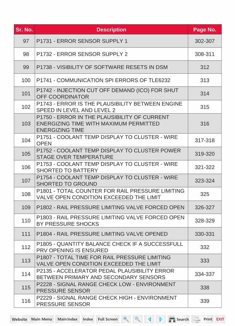
Sr. No. Description Page No.
97 P1731 - ERROR SENSOR SUPPLY 1 302-307
98 P1732 - ERROR SENSOR SUPPLY 2 308-311
99 P1738 - VISIBILITY OF SOFTWARE RESETS IN DSM 312
100 P1741 - COMMUNICATION SPI ERRORS OF TLE6232 313
101P1742 - INJECTION CUT OFF DEMAND (ICO) FOR SHUT OFF COORDINATOR
314
102P1743 - ERROR IS THE PLAUSIBILITY BETWEEN ENGINE SPEED IN LEVEL AND LEVEL 2
315
103P1750 - ERROR IN THE PLAUSIBILITY OF CURRENT ENERGIZING TIME WITH MAXIMUM PERMITTED ENERGIZING TIME
316
104P1751 - COOLANT TEMP DISPLAY TO CLUSTER - WIRE OPEN
317-318
105P1752 - COOLANT TEMP DISPLAY TO CLUSTER POWER STAGE OVER TEMPERATURE
319-320
106P1753 - COOLANT TEMP DISPLAY TO CLUSTER - WIRE SHORTED TO BATTERY
321-322
107P1754 - COOLANT TEMP DISPLAY TO CLUSTER - WIRE SHORTED TO GROUND
323-324
108P1801 - TOTAL COUNTER FOR RAIL PRESSURE LIMITING VALVE OPEN CONDITION EXCEEDED THE LIMIT
325
109 P1802 - RAIL PRESSURE LIMITING VALVE FORCED OPEN 326-327
110P1803 - RAIL PRESSURE LIMITING VALVE FORCED OPEN BY PRESSURE SHOCKS
328-329
111 P1804 - RAIL PRESSURE LIMITING VALVE OPENED 330-331
112P1805 - QUANTITY BALANCE CHECK IF A SUCCESSFULL PRV OPENING IS ENSURED
332
113P1807 - TOTAL TIME FOR RAIL PRESSURE LIMITING VALVE OPEN CONDITION EXCEEDED THE LIMIT
333
114P2135 - ACCELERATOR PEDAL PLAUSIBILITY ERROR BETWEEN PRIMARY AND SECONDARY SENSORS
334-337
115P2228 - SIGNAL RANGE CHECK LOW - ENVIRONMENT PRESSURE SENSOR
338
116P2229 - SIGNAL RANGE CHECK HIGH - ENVIRONMENT PRESSURE SENSOR
339
https://www.truck-manuals.net/

73G
DIAGNOSTIC MANUAL
P0003 - SHORT CIRCUIT TO GROUND OF METERING UNIT OUTPUT
The metering unit is used for compressing the fuel at high pressure and sending it at pressurized stage towards the rail, which is controlled by ECU.
Possible Causes
• Pump metering unit short circuit to ground
• Wiring harness problem
DTC Information
DTC Reaction
• The rail pressure line get damaged with warning light in cluster.
Lamp Status
The check engine (CHK ENG) lamp in the instrument cluster blinks.
Metering Unit Location
1https://www.truck-manuals.net/
74G
DIAGNOSTIC MANUAL
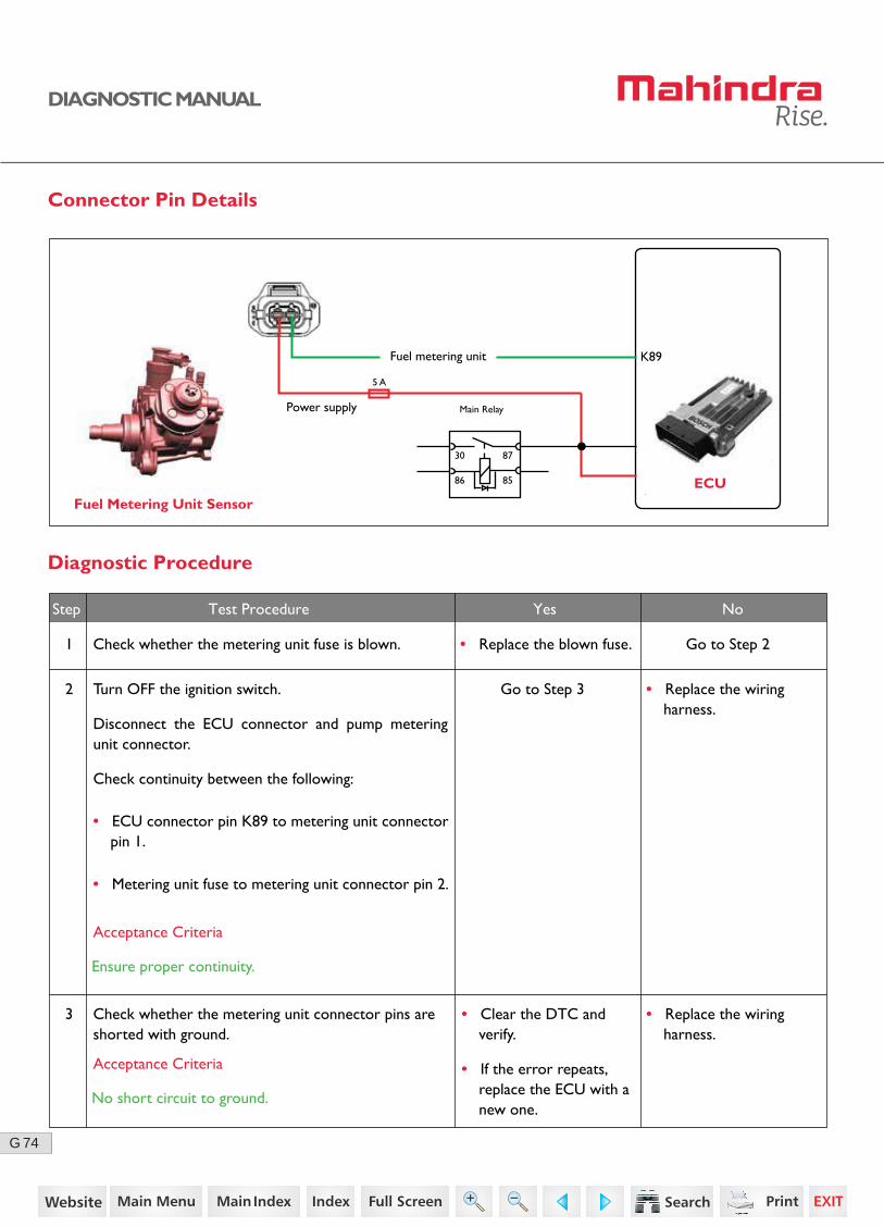
Connector Pin Details
Fuel Metering Unit SensorECU
K89
Diagnostic Procedure
1 Check whether the metering unit fuse is blown.
Check whether the metering unit connector pins are shorted with ground.
Go to Step 2
Go to Step 3
• Replace the blown fuse.
Step Test Procedure Yes No
2
3
Turn OFF the ignition switch.
Disconnect the ECU connector and pump metering unit connector.
Check continuity between the following:
• Replace the wiring harness.
• ECU connector pin K89 to metering unit connector pin 1.
• Metering unit fuse to metering unit connector pin 2.
Acceptance Criteria
Ensure proper continuity.
Acceptance Criteria
No short circuit to ground.
Fuel metering unit
Power supply
30
5 A
86 85
87
Main Relay
• Replace the wiring harness.
• Clear the DTC and verify.
• If the error repeats, replace the ECU with a new one.
2https://www.truck-manuals.net/

75G
DIAGNOSTIC MANUAL
• Clear the DTC and verify using the FES diagnostic tool.
• Activate the ignition for one driving cycle (ignition-OFF and ON).
Healing Condition
After performing the troubleshooting for each P Code, follow the below test procedure before driving the vehicle.
Upon completion of diagnostic procedure, clear the DTC. Ensure that the problem has been rectified and the DTC does not appear again.
3https://www.truck-manuals.net/
76G
DIAGNOSTIC MANUAL
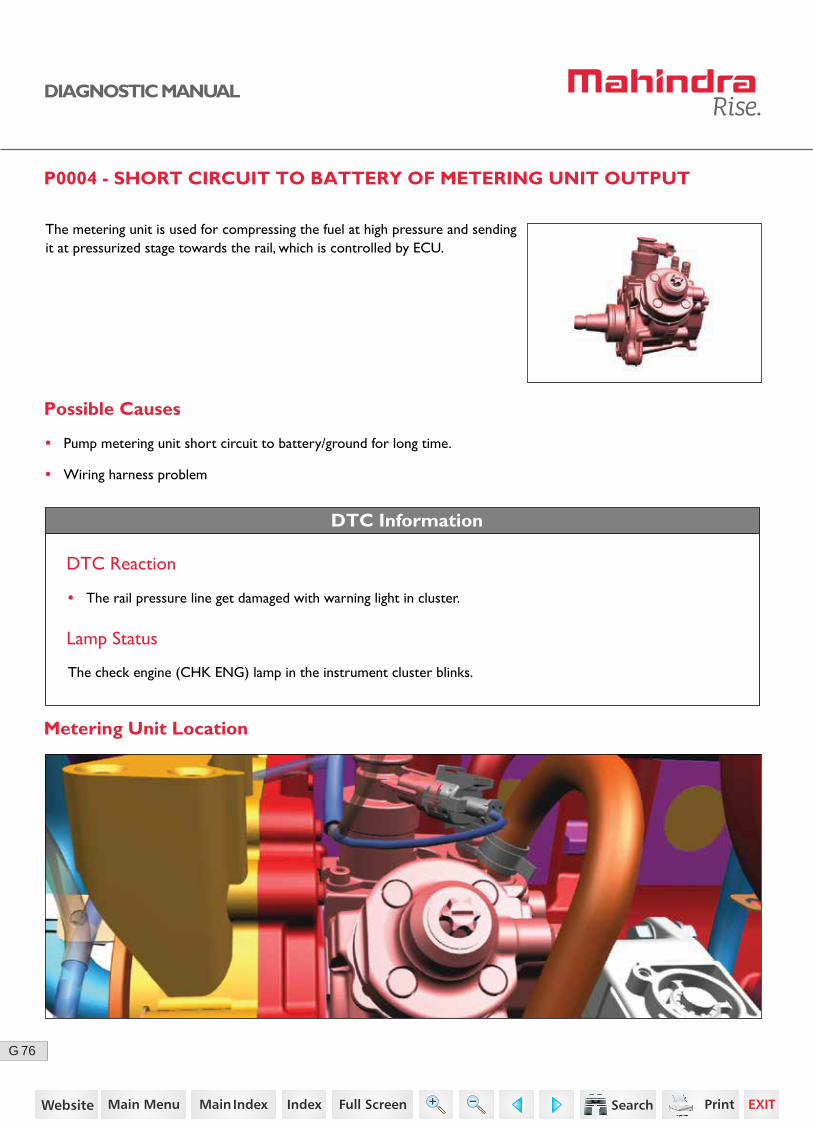
P0004 - SHORT CIRCUIT TO BATTERY OF METERING UNIT OUTPUT
The metering unit is used for compressing the fuel at high pressure and sending it at pressurized stage towards the rail, which is controlled by ECU.
Possible Causes
• Pump metering unit short circuit to battery/ground for long time.
• Wiring harness problem
DTC Information
DTC Reaction
• The rail pressure line get damaged with warning light in cluster.
Lamp Status
The check engine (CHK ENG) lamp in the instrument cluster blinks.
Metering Unit Location
4https://www.truck-manuals.net/
77G
DIAGNOSTIC MANUAL
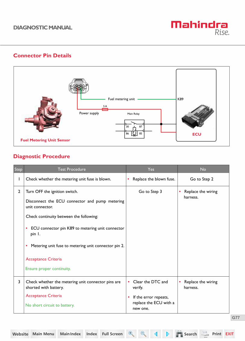
Connector Pin Details
Diagnostic Procedure
1 Check whether the metering unit fuse is blown.
Check whether the metering unit connector pins are shorted with battery.
Go to Step 2
Go to Step 3
• Replace the blown fuse.
Step Test Procedure Yes No
2
3
Turn OFF the ignition switch.
Disconnect the ECU connector and pump metering unit connector.
Check continuity between the following:
• Replace the wiring harness.
• ECU connector pin K89 to metering unit connector pin 1.
• Metering unit fuse to metering unit connector pin 2.
Acceptance Criteria
Ensure proper continuity.
Acceptance Criteria
No short circuit to battery.
Fuel Metering Unit SensorECU
K89Fuel metering unit
Power supply
30
5 A
86 85
87
Main Relay
• Replace the wiring harness.
• Clear the DTC and verify.
• If the error repeats, replace the ECU with a new one.
5https://www.truck-manuals.net/
78G
DIAGNOSTIC MANUAL
• Clear the DTC and verify using the FES diagnostic tool.
• Activate the ignition for one driving cycle (ignition-OFF and ON).
Healing Condition
After performing the troubleshooting for each P Code, follow the below test procedure before driving the vehicle.
Upon completion of diagnostic procedure, clear the DTC. Ensure that the problem has been rectified and the DTC does not appear again.
6https://www.truck-manuals.net/
79G
DIAGNOSTIC MANUAL
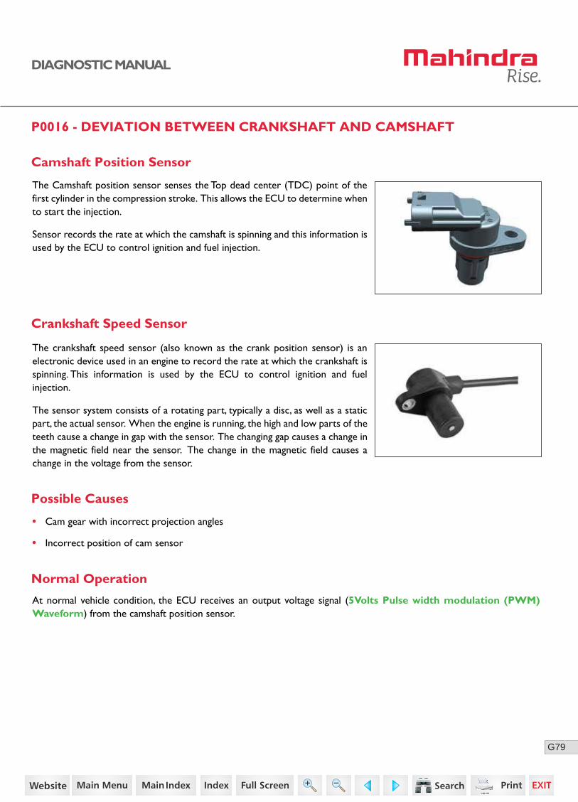
P0016 - DEVIATION BETWEEN CRANKSHAFT AND CAMSHAFT
Possible Causes
The Camshaft position sensor senses the Top dead center (TDC) point of the first cylinder in the compression stroke. This allows the ECU to determine when to start the injection.
Sensor records the rate at which the camshaft is spinning and this information is used by the ECU to control ignition and fuel injection.
• Cam gear with incorrect projection angles
• Incorrect position of cam sensor
Normal Operation
The crankshaft speed sensor (also known as the crank position sensor) is an electronic device used in an engine to record the rate at which the crankshaft is spinning. This information is used by the ECU to control ignition and fuel injection.
The sensor system consists of a rotating part, typically a disc, as well as a static part, the actual sensor. When the engine is running, the high and low parts of the teeth cause a change in gap with the sensor. The changing gap causes a change in the magnetic field near the sensor. The change in the magnetic field causes a change in the voltage from the sensor.
Camshaft Position Sensor
Crankshaft Speed Sensor
At normal vehicle condition, the ECU receives an output voltage signal (5Volts Pulse width modulation (PWM) Waveform) from the camshaft position sensor.
7https://www.truck-manuals.net/
80G
DIAGNOSTIC MANUAL
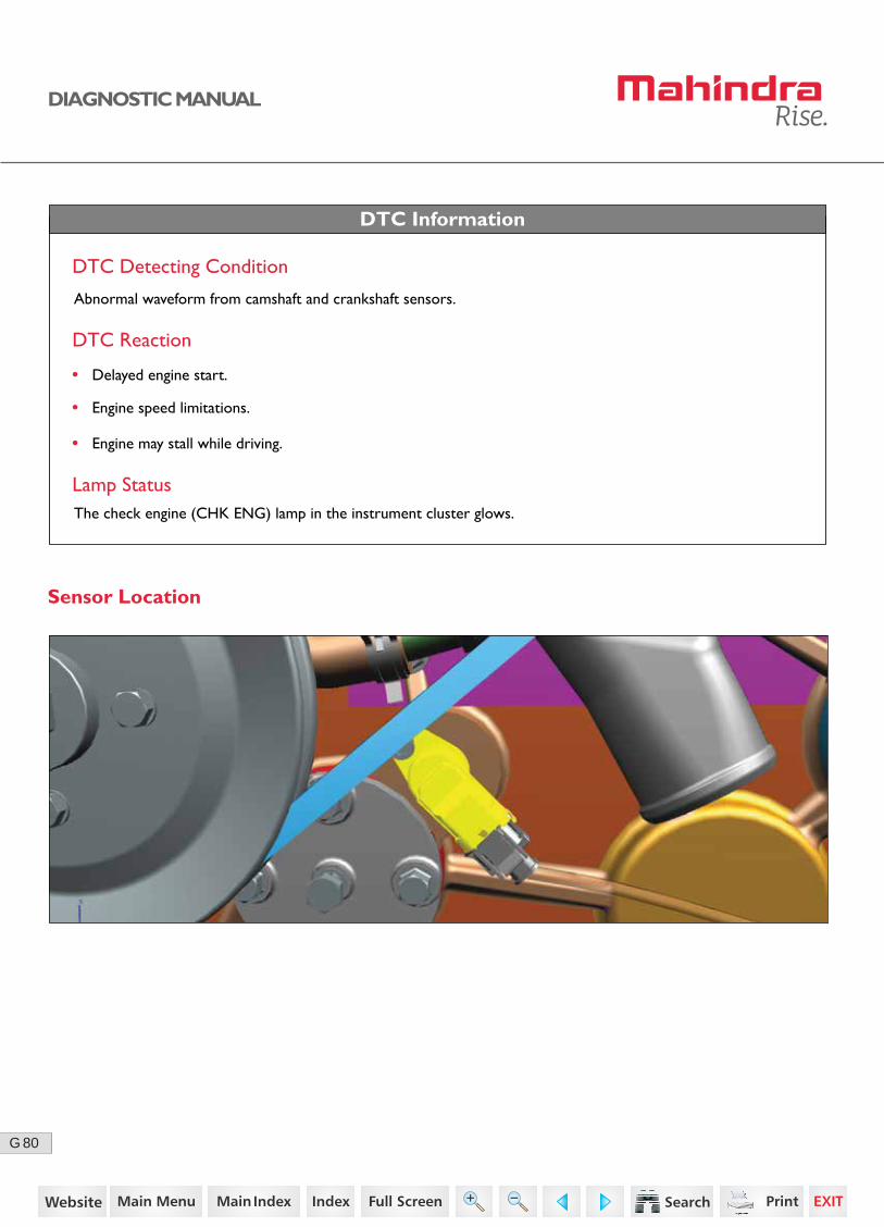
Sensor Location
DTC Information
DTC Detecting Condition
DTC Reaction
Lamp StatusThe check engine (CHK ENG) lamp in the instrument cluster glows.
• Delayed engine start.
• Engine speed limitations.
• Engine may stall while driving.
Abnormal waveform from camshaft and crankshaft sensors.
8https://www.truck-manuals.net/
81G
3 2 1
DIAGNOSTIC MANUAL
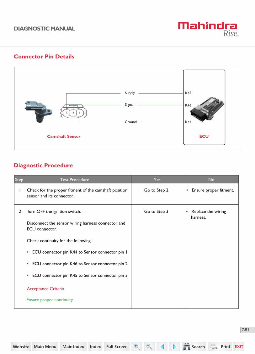
Connector Pin Details
Camshaft Sensor ECU
K46
K45Supply
Ground
Signal
K44
Diagnostic Procedure
Step Test Procedure Yes No
1 Go to Step 2 • Ensure proper fitment.
2 Turn OFF the ignition switch.
Disconnect the sensor wiring harness connector and ECU connector.
Check continuity for the following:
• ECU connector pin K44 to Sensor connector pin 1
• ECU connector pin K46 to Sensor connector pin 2
• ECU connector pin K45 to Sensor connector pin 3
Go to Step 3
Acceptance Criteria
Ensure proper continuity.
• Replace the wiring harness.
Check for the proper fitment of the camshaft position sensor and its connector.
9https://www.truck-manuals.net/
82G
DIAGNOSTIC MANUAL
Step Test Procedure Yes No
• Clear the DTC and verify using the FES diagnostic tool.
• Activate the ignition for one driving cycle (ignition-OFF and ON).
Healing Condition
After performing the troubleshooting for each P Code, follow the below test procedure before driving the vehicle.
Upon completion of diagnostic procedure, clear the DTC. Ensure that the problem has been rectified and the DTC does not appear again.
• Replace the ECU.
Check for any short circuit between sensor connec-tor pins 2 and 3 with battery positive/ground.
Check for any short circuit between sensor connec-tor pin 1 with battery positive.
4 Connect the ECU connector.
Turn ON the ignition switch.
Check the voltage between sensor connector pin 1 and 3.
3
Go to Step 5
• Replace the wiring harness.
Go to Step 4
Acceptance Criteria
Voltage = 5V (+/- 0.25)
Acceptance Criteria
No short circuit between ground / battery positive.
6 If the problem persists,
Replace the sensor with a new one.
Clear the DTC and verify.
If still error repeats,
Replace the ECU with a new one.
• Ensure proper gap is maintained between sensor tip and cam gear.
5 Check if the gap between the cam sensor tip and cam gear sensing surface.
Go to Step 6
Acceptance Criteria
0.1 to 2.8 mm
10https://www.truck-manuals.net/
83G
DIAGNOSTIC MANUAL
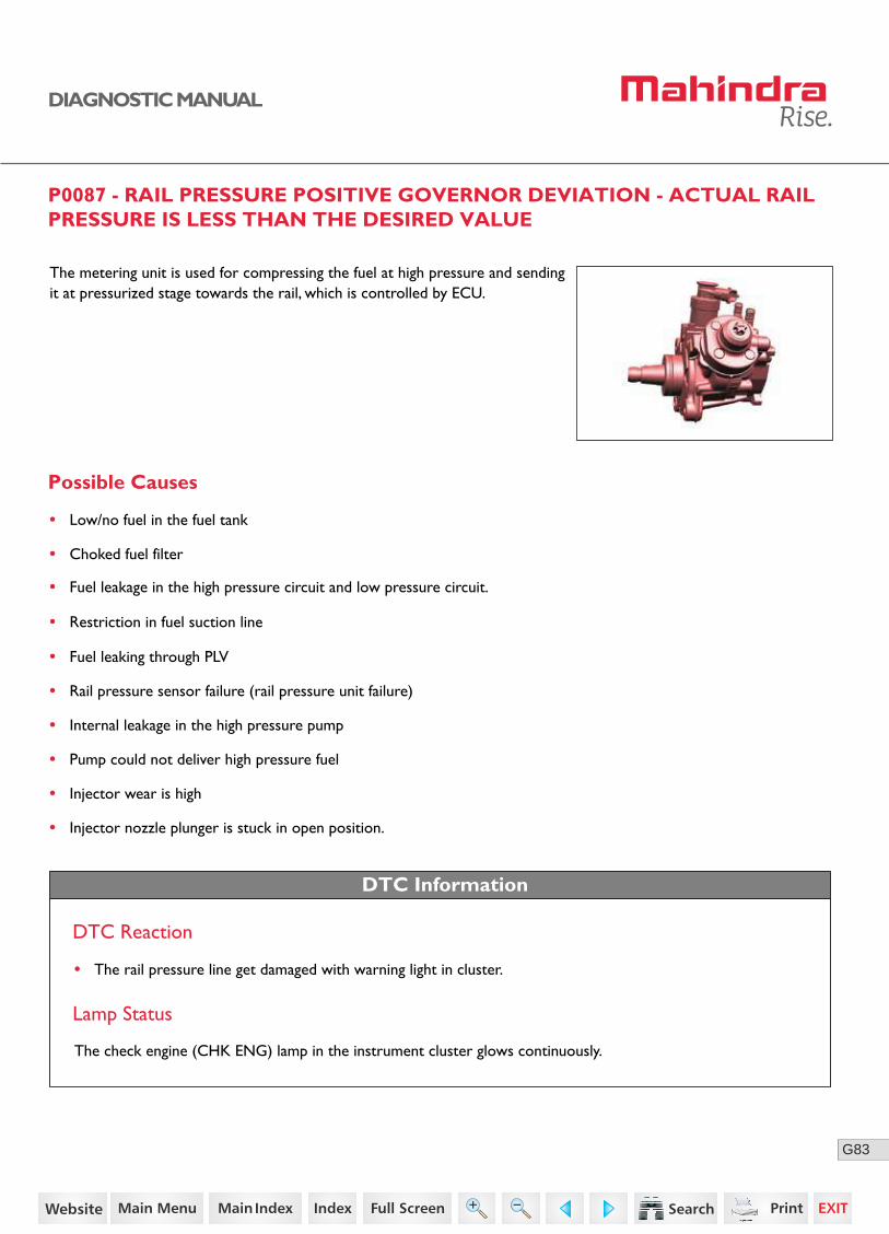
P0087 - RAIL PRESSURE POSITIVE GOVERNOR DEVIATION - ACTUAL RAIL PRESSURE IS LESS THAN THE DESIRED VALUE
The metering unit is used for compressing the fuel at high pressure and sending it at pressurized stage towards the rail, which is controlled by ECU.
Possible Causes
• Low/no fuel in the fuel tank
• Choked fuel filter
• Fuel leakage in the high pressure circuit and low pressure circuit.
• Restriction in fuel suction line
• Fuel leaking through PLV
• Rail pressure sensor failure (rail pressure unit failure)
• Internal leakage in the high pressure pump
• Pump could not deliver high pressure fuel
• Injector wear is high
• Injector nozzle plunger is stuck in open position.
DTC Information
DTC Reaction
• The rail pressure line get damaged with warning light in cluster.
Lamp Status
The check engine (CHK ENG) lamp in the instrument cluster glows continuously.
11https://www.truck-manuals.net/

84G
DIAGNOSTIC MANUAL
Metering Unit Location
Connector Pin Details
Fuel Metering Unit SensorECU
K89Fuel metering unit
Power supply
30
5 A
86 85
87
Main Relay
12https://www.truck-manuals.net/

85G
DIAGNOSTIC MANUAL
Diagnostic Procedure
1 Ensure sufficient fuel is available in the fuel tank. Go to Step 2 • Top-up the fuel in the fuel tank.
2 Check whether the fuel filter is chocked. Go to Step 3• Replaced the chocked fuel filter.
3 Check for fuel leakage in high pressure circuit and low pressure circuit.
Go to Step 4• Ensure proper connec-tions.
4 Check for the bends/crimps in the fuel suction line. Go to Step 5• Change the fuel suction line.
5 Check for any error related to Rail Pressure Sensor, PRV, Metering unit.
Go to Step 6• Rectify corresponding error and clear and verify DTC again
• Replace the rail, If error repeats
6 Internal leakage in the high pressure pump.
Pump could not deliver high pressure fuel.
7 Injector wear is high.
Injector nozzle plunger is stuck in open position.
• Remove the pump. Get it checked by the autho-rized dealer.
• Clear the DTC and verify.
• Remove the injector. Get it checked by the autho-rized dealer.
• Clear the DTC and verify.
Step Test Procedure Yes No
• Clear the DTC and verify using the FES diagnostic tool.
• Activate the ignition for one driving cycle (ignition-OFF and ON).
Healing Condition
After performing the troubleshooting for each P Code, follow the below test procedure before driving the vehicle.
Upon completion of diagnostic procedure, clear the DTC. Ensure that the problem has been rectified and the DTC does not appear again.
13https://www.truck-manuals.net/
86G
DIAGNOSTIC MANUAL
P0117 - SIGNAL RANGE CHECK LOW - COOLANT TEMPERATURE SENSOR
Possible Causes
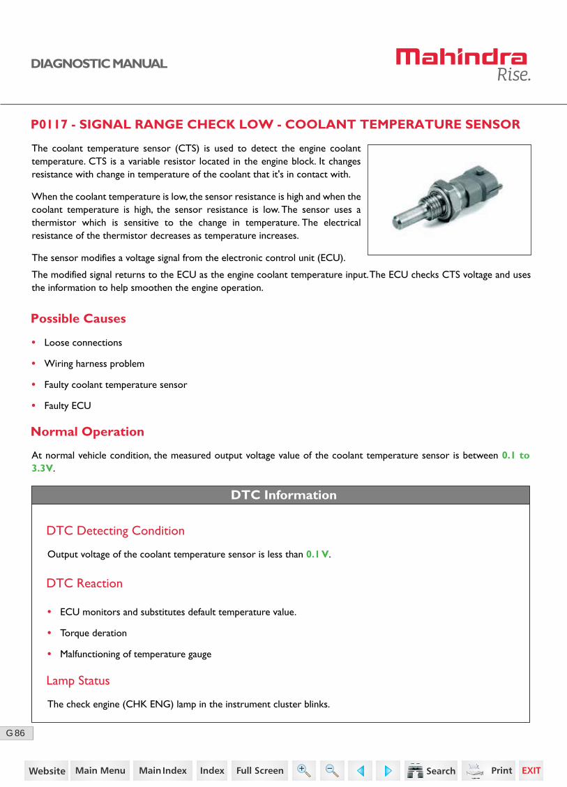
The coolant temperature sensor (CTS) is used to detect the engine coolant temperature. CTS is a variable resistor located in the engine block. It changes resistance with change in temperature of the coolant that it's in contact with.
When the coolant temperature is low, the sensor resistance is high and when the coolant temperature is high, the sensor resistance is low. The sensor uses a thermistor which is sensitive to the change in temperature. The electrical resistance of the thermistor decreases as temperature increases.
The sensor modifies a voltage signal from the electronic control unit (ECU).
• Loose connections
• Wiring harness problem
• Faulty coolant temperature sensor
• Faulty ECU
• ECU monitors and substitutes default temperature value.
• Torque deration
• Malfunctioning of temperature gauge
Normal Operation
DTC Information
At normal vehicle condition, the measured output voltage value of the coolant temperature sensor is between 0.1 to 3.3V.
DTC Detecting Condition
Output voltage of the coolant temperature sensor is less than 0.1 V.
DTC Reaction
Lamp Status
The check engine (CHK ENG) lamp in the instrument cluster blinks.
The modified signal returns to the ECU as the engine coolant temperature input. The ECU checks CTS voltage and uses the information to help smoothen the engine operation.
14https://www.truck-manuals.net/

87G
DIAGNOSTIC MANUAL
Sensor Location
Connector Pin Details
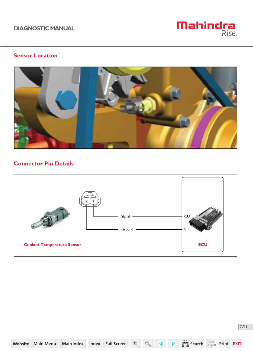
Coolant Temperature Sensor ECU
Signal
Ground K11
K33
2 1
15https://www.truck-manuals.net/
88G
DIAGNOSTIC MANUAL
Diagnostic Procedure
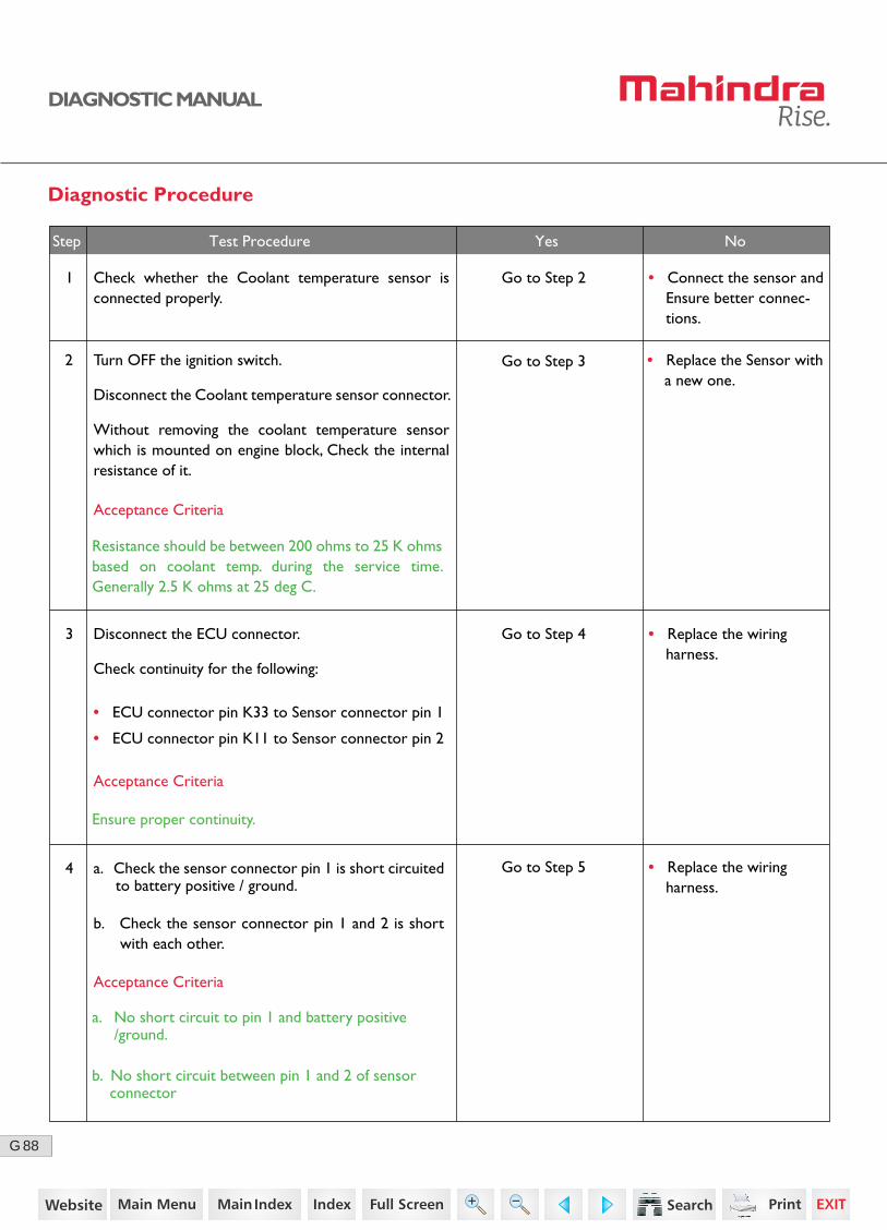
Disconnect the ECU connector.
Check continuity for the following:
• ECU connector pin K33 to Sensor connector pin 1
• ECU connector pin K11 to Sensor connector pin 2
3 Go to Step 4
Go to Step 5
Go to Step 3
• Replace the wiring harness.
Acceptance Criteria
Ensure proper continuity.
Step Test Procedure Yes No
2 Turn OFF the ignition switch.
Disconnect the Coolant temperature sensor connector.
Without removing the coolant temperature sensor which is mounted on engine block, Check the internal resistance of it.
• Replace the Sensor with a new one.
Acceptance Criteria
Resistance should be between 200 ohms to 25 K ohms based on coolant temp. during the service time. Generally 2.5 K ohms at 25 deg C.
1 Check whether the Coolant temperature sensor is connected properly.
Go to Step 2 • Connect the sensor and Ensure better connec-tions.
4 a. Check the sensor connector pin 1 is short circuited to battery positive / ground.
b. Check the sensor connector pin 1 and 2 is short with each other.
Acceptance Criteria
a. No short circuit to pin 1 and battery positive /ground.
b. No short circuit between pin 1 and 2 of sensor connector
• Replace the wiring harness.
16https://www.truck-manuals.net/
89G
DIAGNOSTIC MANUAL
• Clear the DTC and verify using the FES diagnostic tool.
• Activate the ignition for one driving cycle (ignition-OFF and ON).
After performing the troubleshooting for each P Code, follow the below test procedure before driving the vehicle.
Upon completion of diagnostic procedure, clear the DTC. Ensure that the problem has been rectified and the DTC does not appear again.
Healing Condition
Step Test Procedure Yes No
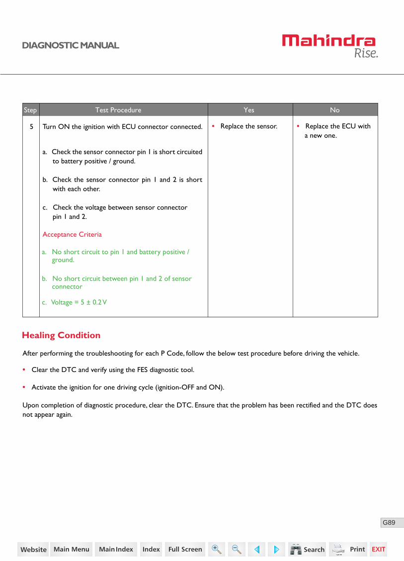
5 Turn ON the ignition with ECU connector connected.
a. Check the sensor connector pin 1 is short circuited to battery positive / ground.
b. Check the sensor connector pin 1 and 2 is short with each other.
c. Check the voltage between sensor connector pin 1 and 2.
Acceptance Criteria
a. No short circuit to pin 1 and battery positive / ground.
c. Voltage = 5 ± 0.2 V
b. No short circuit between pin 1 and 2 of sensor connector
• Replace the sensor. • Replace the ECU with a new one.
17https://www.truck-manuals.net/

90G
DIAGNOSTIC MANUAL
P0118 - SIGNAL RANGE CHECK HIGH - COOLANT TEMPERATURE SENSOR
The coolant temperature sensor (CTS) is used to detect the engine coolant temperature. CTS is a variable resistor located in the engine block. It changes resistance with change in temperature of the coolant that it's in contact with.
When the coolant temperature is low, the sensor resistance is high and when the coolant temperature is high, the sensor resistance is low. The sensor uses a thermistor which is sensitive to the change in temperature. The electrical resistance of the thermistor decreases as temperature increases.
The sensor modifies a voltage signal from the electronic control unit (ECU).
Output voltage of the coolant temperature sensor is more than 3.3 V.
The modified signal returns to the ECU as the engine coolant temperature input. The ECU checks CTS voltage and uses the information to help smoothen the engine operation.
Possible Causes
• Loose connections
• Wiring harness problem
• Faulty coolant temperature sensor
• Faulty ECU
Normal Operation
At normal vehicle condition, the measured output voltage value of the coolant temperature sensor is between 0.1 to 3.3V.
• ECU monitors and substitutes default temperature value
• Torque deration
• Malfunctioning of temperature gauge
DTC Information
DTC Detecting Condition
DTC Reaction
Lamp Status
The check engine (CHK ENG) lamp in the instrument cluster blinks.
18https://www.truck-manuals.net/
91G
DIAGNOSTIC MANUAL
Sensor Location
Connector Pin Details
Coolant Temperature Sensor ECU
Signal
Ground K11
K33
2 1
19https://www.truck-manuals.net/

92G
DIAGNOSTIC MANUAL
Diagnostic Procedure
Disconnect the ECU connector.
Check continuity for the following:
• ECU connector pin K33 to Sensor connector pin 1
• ECU connector pin K11 to Sensor connector pin 2
3 Go to Step 4
Go to Step 5
Go to Step 3
• Replace the wiring harness.
Acceptance Criteria
Ensure proper continuity.
Step Test Procedure Yes No
2 Turn OFF the ignition switch.
Disconnect the Coolant temperature sensor connector.
Without removing the coolant temperature sensor which is mounted on engine block, Check the internal resistance of it.
• Replace the Sensor with a new one.
Acceptance Criteria
Resistance should be between 200 ohms to 25 K ohms based on coolant temp. during the service time. Generally 2.5 K ohms at 25 deg C.
1 Check whether the Coolant temperature sensor is connected properly.
Go to Step 2 • Connect the sensor and Ensure better connec-tions.
4 a. Check the sensor connector pin 1 is short circuited to battery positive / ground.
b. Check the sensor connector pin 1 and 2 is short with each other.
Acceptance Criteria
a. No short circuit to pin 1 and battery positive /ground.
b. No short circuit between pin 1 and 2 of sensor connector
• Replace the wiring harness.
20https://www.truck-manuals.net/

93G
DIAGNOSTIC MANUAL
• Clear the DTC and verify using the FES diagnostic tool.
• Activate the ignition for one driving cycle (ignition-OFF and ON).
After performing the troubleshooting for each P Code, follow the below test procedure before driving the vehicle.
Upon completion of diagnostic procedure, clear the DTC. Ensure that the problem has been rectified and the DTC does not appear again.
Healing Condition
Step Test Procedure Yes No
5 Turn ON the ignition with ECU connector connected.
a. Check the sensor connector pin 1 is short circuited to battery positive / ground.
b. Check the sensor connector pin 1 and 2 is short with each other.
c. Check the voltage between sensor connector pin 1 and 2.
Acceptance Criteria
a. No short circuit to pin 1 and battery positive / ground.
c. Voltage = 5 ± 0.2 V
b. No short circuit between pin 1 and 2 of sensor connector
• Replace the sensor. • Replace the ECU with a new one.
21https://www.truck-manuals.net/
94G
DIAGNOSTIC MANUAL
P0122 - SIGNAL RANGE CHECK LOW - PRIMARY ACCELERATOR PEDAL
Possible Causes
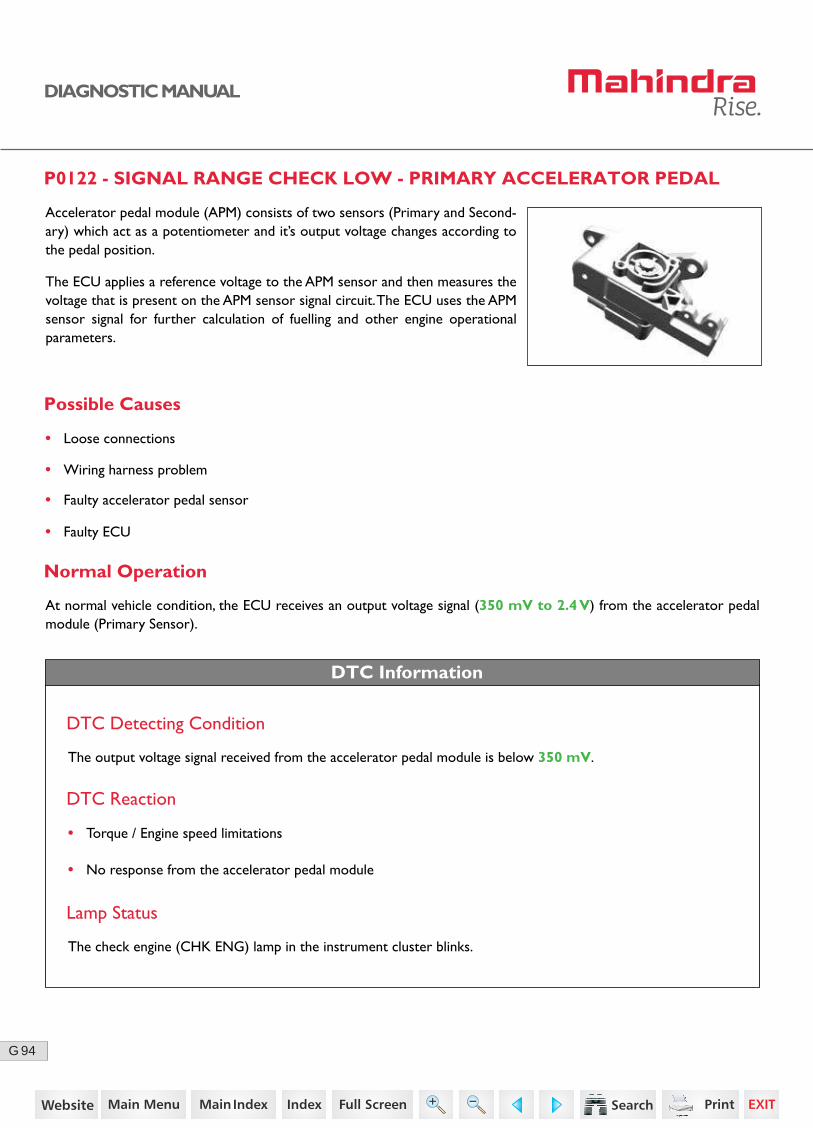
Accelerator pedal module (APM) consists of two sensors (Primary and Second-ary) which act as a potentiometer and it’s output voltage changes according to the pedal position.
The ECU applies a reference voltage to the APM sensor and then measures the voltage that is present on the APM sensor signal circuit. The ECU uses the APM sensor signal for further calculation of fuelling and other engine operational parameters.
• Loose connections
• Wiring harness problem
• Faulty accelerator pedal sensor
• Faulty ECU
Normal Operation
DTC Information
At normal vehicle condition, the ECU receives an output voltage signal (350 mV to 2.4 V) from the accelerator pedal module (Primary Sensor).
DTC Detecting Condition
The output voltage signal received from the accelerator pedal module is below 350 mV.
DTC Reaction
• Torque / Engine speed limitations
• No response from the accelerator pedal module
Lamp Status
The check engine (CHK ENG) lamp in the instrument cluster blinks.
22https://www.truck-manuals.net/
95G
DIAGNOSTIC MANUAL
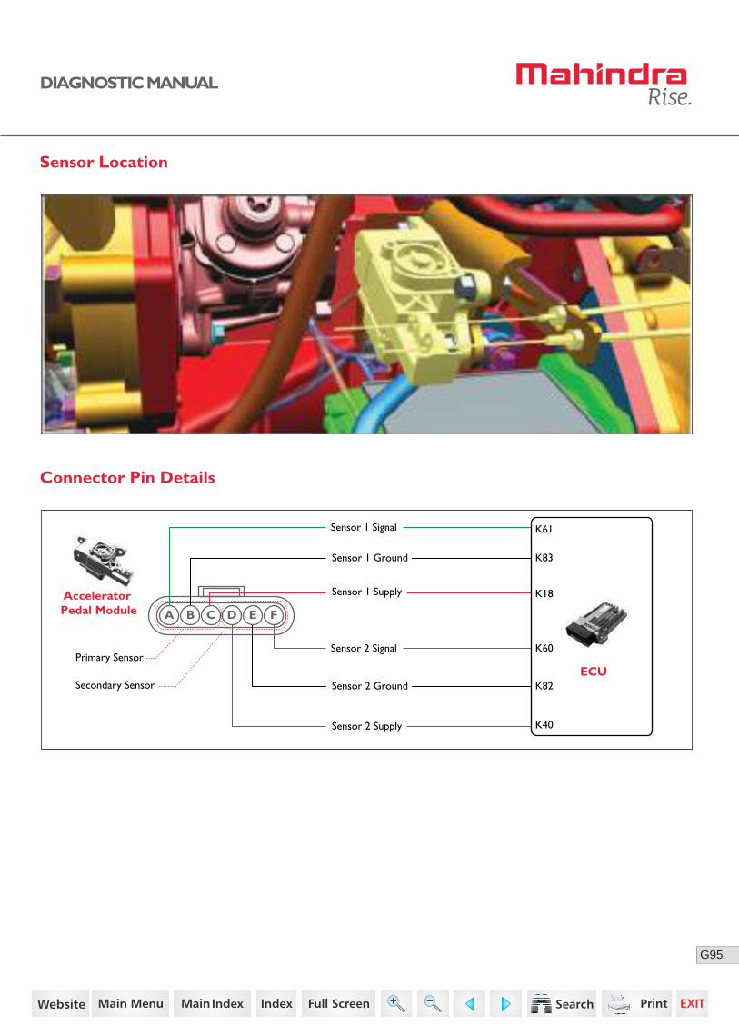
Sensor Location
Connector Pin Details
K40
K18
K83
K61Sensor 1 Signal
Primary Sensor
Secondary Sensor
Sensor 2 Signal
Sensor 1 Ground
Sensor 2 Ground
Sensor 1 SupplyAccelerator Pedal Module
ECU
Sensor 2 Supply
K82
K60
A B C D E F
23https://www.truck-manuals.net/
96G
DIAGNOSTIC MANUAL
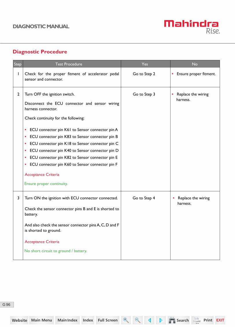
Diagnostic Procedure
2
3
Turn OFF the ignition switch.
Disconnect the ECU connector and sensor wiring harness connector.
Check continuity for the following:
• ECU connector pin K61 to Sensor connector pin A
• ECU connector pin K83 to Sensor connector pin B
• ECU connector pin K18 to Sensor connector pin C
• ECU connector pin K40 to Sensor connector pin D
• ECU connector pin K82 to Sensor connector pin E
• ECU connector pin K60 to Sensor connector pin F
Turn ON the ignition with ECU connector connected.
Check the sensor connector pins B and E is shorted to battery.
And also check the sensor connector pins A, C, D and F is shorted to ground.
Go to Step 3 • Replace the wiring harness.
• Replace the wiring harness.
Acceptance Criteria
Ensure proper continuity.
Acceptance Criteria
No short circuit to ground / battery.
Step Test Procedure Yes No
1 Go to Step 2 • Ensure proper fitment.Check for the proper fitment of accelerator pedal sensor and connector.
Go to Step 4
24https://www.truck-manuals.net/

97G
DIAGNOSTIC MANUAL
• Clear the DTC and verify using the FES diagnostic tool.
• Activate the ignition for one driving cycle (ignition-OFF and ON).
Healing Condition
After performing the troubleshooting for each P Code, follow the below test procedure before driving the vehicle.
Upon completion of diagnostic procedure, clear the DTC. Ensure that the problem has been rectified and the DTC does not appear again.
Step Test Procedure Yes No
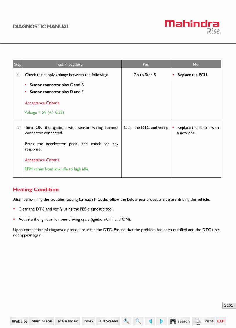
5 Turn ON the ignition with sensor wiring harness connector connected.
Press the accelerator pedal and check for any response.
Clear the DTC and verify. • Replace the sensor with a new one.
• Replace the ECU.4 Check the supply voltage between the following:
• Sensor connector pins C and B
• Sensor connector pins D and E
Go to Step 5
Acceptance Criteria
Voltage = 5V (+/- 0.25)
Acceptance Criteria
RPM varies from low idle to high idle.
25https://www.truck-manuals.net/
98G
DIAGNOSTIC MANUAL
P0123 - SIGNAL RANGE CHECK HIGH - PRIMARY ACCELERATOR PEDAL
Possible Causes
• Loose connections
• Wiring harness problem
• Faulty accelerator pedal sensor
• Faulty ECU
Normal Operation
DTC Information
At normal vehicle condition, the ECU receives an output voltage signal (350 mV to 2.4 V) from the accelerator pedal module (Primary Sensor).
DTC Detecting Condition
The output voltage signal received from the accelerator pedal module is above 2.4 V.
DTC Reaction
• Torque / Engine speed limitations
• No response from the accelerator pedal module
Lamp Status
The check engine (CHK ENG) lamp in the instrument cluster blinks.
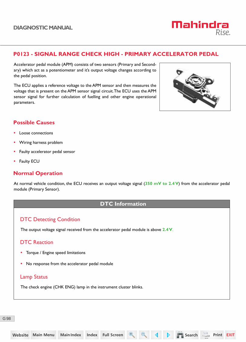
Accelerator pedal module (APM) consists of two sensors (Primary and Second-ary) which act as a potentiometer and it’s output voltage changes according to the pedal position.
The ECU applies a reference voltage to the APM sensor and then measures the voltage that is present on the APM sensor signal circuit. The ECU uses the APM sensor signal for further calculation of fuelling and other engine operational parameters.
26https://www.truck-manuals.net/

99G
DIAGNOSTIC MANUAL
Sensor LocationSensor Location
Connector Pin Details
K40
K18
K83
K61Sensor 1 Signal
Primary Sensor
Secondary Sensor
Sensor 2 Signal
Sensor 1 Ground
Sensor 2 Ground
Sensor 1 SupplyAccelerator Pedal Module
ECU
Sensor 2 Supply
K82
K60
A B C D E F
27https://www.truck-manuals.net/

100G
DIAGNOSTIC MANUAL
Diagnostic Procedure
2
3
Turn OFF the ignition switch.
Disconnect the ECU connector and sensor wiring harness connector.
Check continuity for the following:
• ECU connector pin K61 to Sensor connector pin A
• ECU connector pin K83 to Sensor connector pin B
• ECU connector pin K18 to Sensor connector pin C
• ECU connector pin K40 to Sensor connector pin D
• ECU connector pin K82 to Sensor connector pin E
• ECU connector pin K60 to Sensor connector pin F
Turn ON the ignition with ECU connector connected.
Check the sensor connector pins B and E is shorted to battery.
And also check the sensor connector pins A, C, D and F is shorted to ground.
Go to Step 3 • Replace the wiring harness.
Acceptance Criteria
Ensure proper continuity.
Acceptance Criteria
No short circuit to ground / battery.
Step Test Procedure Yes No
1 Go to Step 2 • Ensure proper fitment.Check for the proper fitment of accelerator pedal sensor and connector.
Go to Step 4 • Replace the wiring harness.
28https://www.truck-manuals.net/
101G
DIAGNOSTIC MANUAL
• Clear the DTC and verify using the FES diagnostic tool.
• Activate the ignition for one driving cycle (ignition-OFF and ON).
Healing Condition
After performing the troubleshooting for each P Code, follow the below test procedure before driving the vehicle.
Upon completion of diagnostic procedure, clear the DTC. Ensure that the problem has been rectified and the DTC does not appear again.
Step Test Procedure Yes No
5 Turn ON the ignition with sensor wiring harness connector connected.
Press the accelerator pedal and check for any response.
Clear the DTC and verify. • Replace the sensor with a new one.
• Replace the ECU.4 Check the supply voltage between the following:
• Sensor connector pins C and B
• Sensor connector pins D and E
Go to Step 5
Acceptance Criteria
Voltage = 5V (+/- 0.25)
Acceptance Criteria
RPM varies from low idle to high idle.
29https://www.truck-manuals.net/
102G
DIAGNOSTIC MANUAL
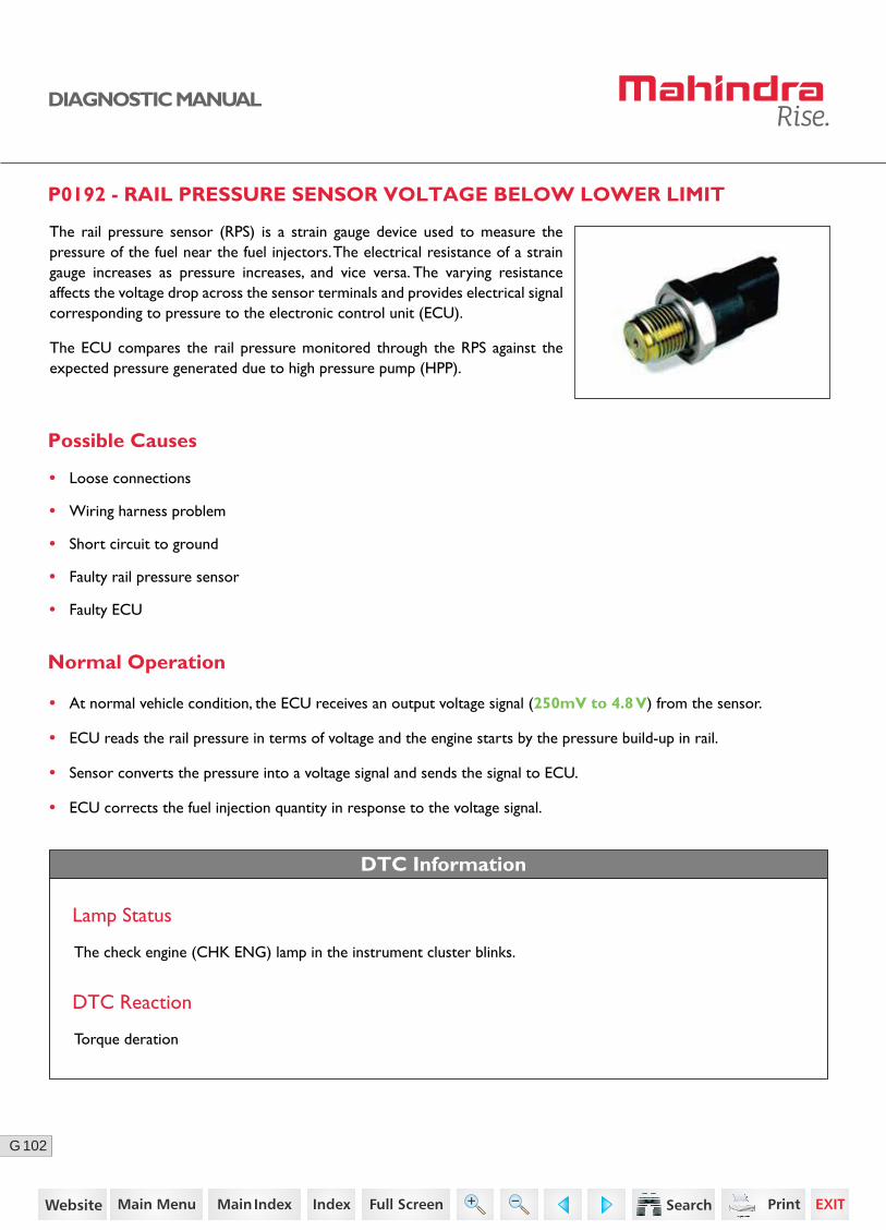
P0192 - RAIL PRESSURE SENSOR VOLTAGE BELOW LOWER LIMIT
Possible Causes
The rail pressure sensor (RPS) is a strain gauge device used to measure the pressure of the fuel near the fuel injectors. The electrical resistance of a strain gauge increases as pressure increases, and vice versa. The varying resistance affects the voltage drop across the sensor terminals and provides electrical signal corresponding to pressure to the electronic control unit (ECU).
The ECU compares the rail pressure monitored through the RPS against the expected pressure generated due to high pressure pump (HPP).
• Loose connections
• Wiring harness problem
• Short circuit to ground
• Faulty rail pressure sensor
• Faulty ECU
Normal Operation
DTC Information
• At normal vehicle condition, the ECU receives an output voltage signal (250mV to 4.8 V) from the sensor.
• ECU reads the rail pressure in terms of voltage and the engine starts by the pressure build-up in rail.
• Sensor converts the pressure into a voltage signal and sends the signal to ECU.
• ECU corrects the fuel injection quantity in response to the voltage signal.
DTC Reaction
Torque deration
Lamp Status
The check engine (CHK ENG) lamp in the instrument cluster blinks.
30https://www.truck-manuals.net/
103G
DIAGNOSTIC MANUAL
02
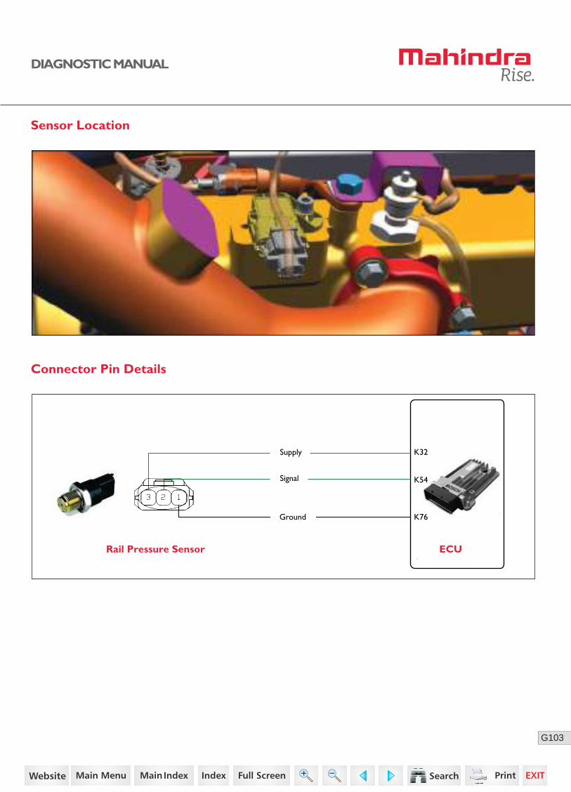
Sensor Location
Rail Pressure Sensor ECU
Connector Pin Details
K54
K32Supply
Ground
Signal
K76
31https://www.truck-manuals.net/
104G
DIAGNOSTIC MANUAL
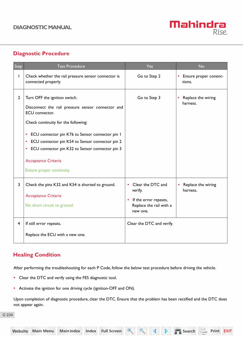
Diagnostic Procedure
2 Turn OFF the ignition switch.
Disconnect the rail pressure sensor connector and ECU connector.
Check continuity for the following:
• ECU connector pin K76 to Sensor connector pin 1
• ECU connector pin K54 to Sensor connector pin 2
• ECU connector pin K32 to Sensor connector pin 3
Go to Step 3 • Replace the wiring harness.
Go to Step 2 • Ensure proper conenc-tions.
3 Check the pins K32 and K54 is shorted to ground.
Acceptance Criteria
Ensure proper continuity.
Acceptance Criteria
No short circuit to ground.
Step Test Procedure Yes No
4 If still error repeats,
Replace the ECU with a new one.
Clear the DTC and verify.
1 Check whether the rail pressure sensor connector is connected properly.
• Clear the DTC and verify using the FES diagnostic tool.
• Activate the ignition for one driving cycle (ignition-OFF and ON).
After performing the troubleshooting for each P Code, follow the below test procedure before driving the vehicle.
Upon completion of diagnostic procedure, clear the DTC. Ensure that the problem has been rectified and the DTC does not appear again.
Healing Condition
• Replace the wiring harness.
• Clear the DTC and verify.
• If the error repeats, Replace the rail with a new one.
32https://www.truck-manuals.net/
105G
DIAGNOSTIC MANUAL
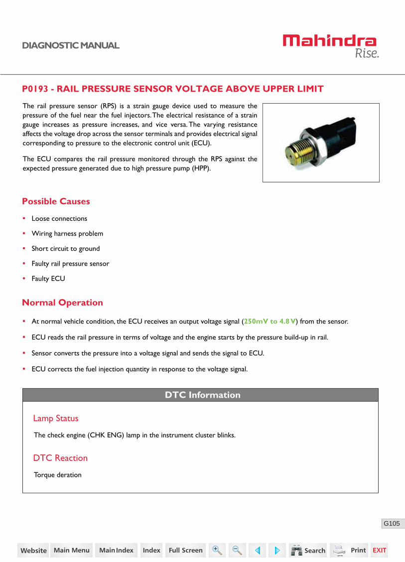
P0193 - RAIL PRESSURE SENSOR VOLTAGE ABOVE UPPER LIMIT
The rail pressure sensor (RPS) is a strain gauge device used to measure the pressure of the fuel near the fuel injectors. The electrical resistance of a strain gauge increases as pressure increases, and vice versa. The varying resistance affects the voltage drop across the sensor terminals and provides electrical signal corresponding to pressure to the electronic control unit (ECU).
The ECU compares the rail pressure monitored through the RPS against the expected pressure generated due to high pressure pump (HPP).
Possible Causes
• Loose connections
• Wiring harness problem
• Short circuit to ground
• Faulty rail pressure sensor
• Faulty ECU
Normal Operation
DTC Information
DTC Reaction
Torque deration
Lamp Status
The check engine (CHK ENG) lamp in the instrument cluster blinks.
• At normal vehicle condition, the ECU receives an output voltage signal (250mV to 4.8 V) from the sensor.
• ECU reads the rail pressure in terms of voltage and the engine starts by the pressure build-up in rail.
• Sensor converts the pressure into a voltage signal and sends the signal to ECU.
• ECU corrects the fuel injection quantity in response to the voltage signal.
33https://www.truck-manuals.net/
106G
DIAGNOSTIC MANUAL
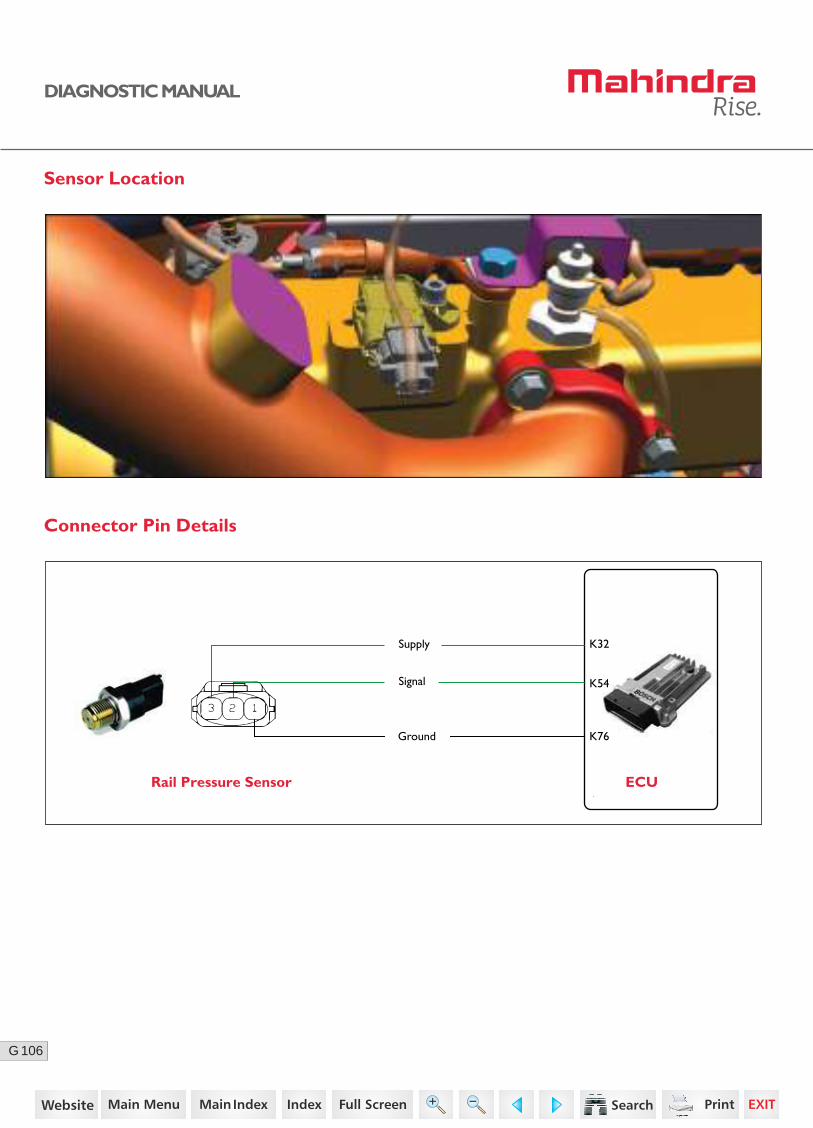
Sensor Location
Connector Pin Details
Rail Pressure Sensor ECU
K54
K32Supply
Ground
Signal
K76
34https://www.truck-manuals.net/
107G
DIAGNOSTIC MANUAL
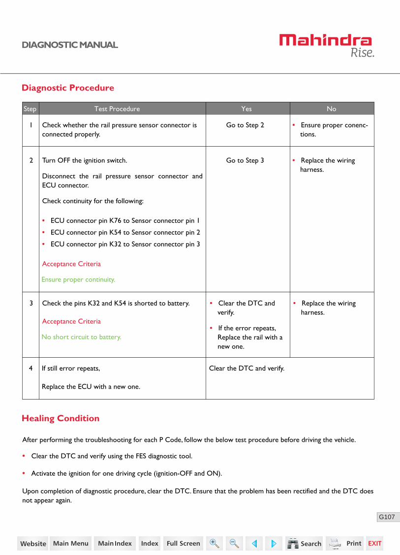
Diagnostic Procedure
2 Turn OFF the ignition switch.
Disconnect the rail pressure sensor connector and ECU connector.
Check continuity for the following:
• ECU connector pin K76 to Sensor connector pin 1
• ECU connector pin K54 to Sensor connector pin 2
• ECU connector pin K32 to Sensor connector pin 3
Go to Step 3 • Replace the wiring harness.
Go to Step 2 • Ensure proper conenc-tions.
3 Check the pins K32 and K54 is shorted to battery.
Acceptance Criteria
Ensure proper continuity.
Acceptance Criteria
No short circuit to battery.
Step Test Procedure Yes No
• Replace the wiring harness.
• Clear the DTC and verify.
• If the error repeats, Replace the rail with a new one.
4 If still error repeats,
Replace the ECU with a new one.
Clear the DTC and verify.
1 Check whether the rail pressure sensor connector is connected properly.
• Clear the DTC and verify using the FES diagnostic tool.
• Activate the ignition for one driving cycle (ignition-OFF and ON).
After performing the troubleshooting for each P Code, follow the below test procedure before driving the vehicle.
Upon completion of diagnostic procedure, clear the DTC. Ensure that the problem has been rectified and the DTC does not appear again.
Healing Condition
35https://www.truck-manuals.net/
108G
DIAGNOSTIC MANUAL
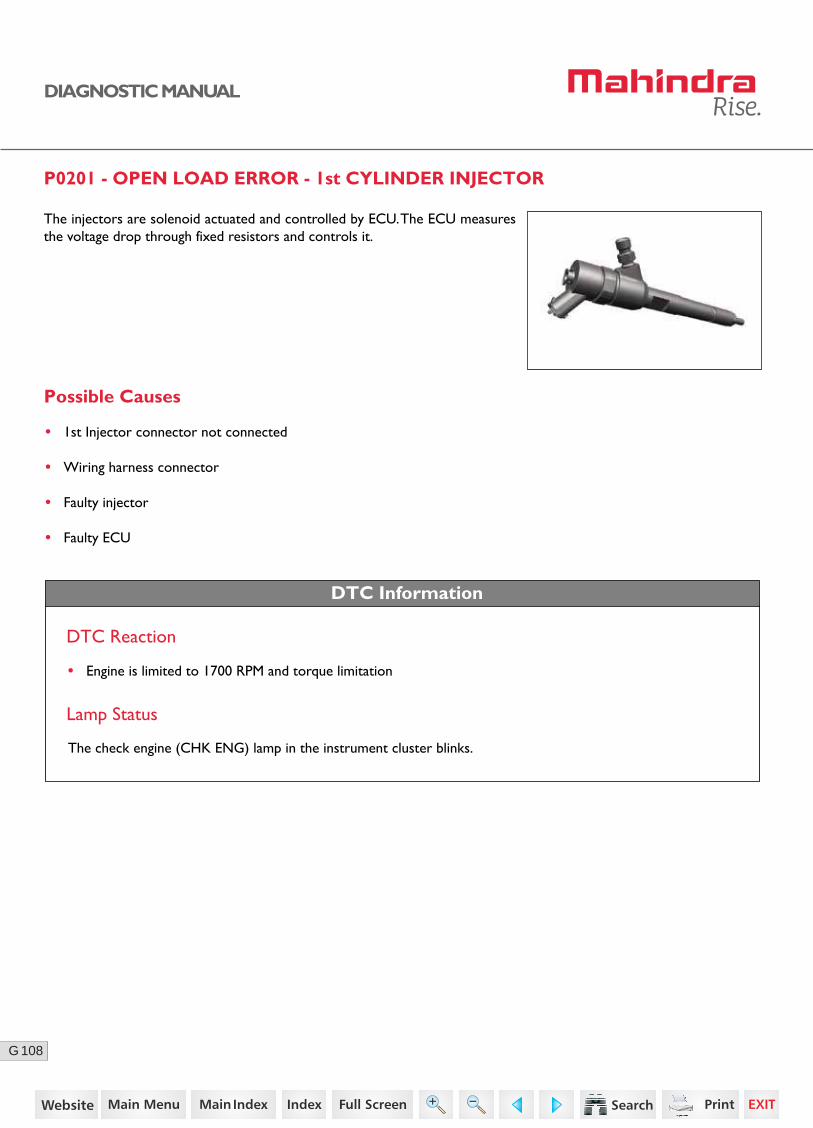
P0201 - OPEN LOAD ERROR - 1st CYLINDER INJECTOR
The injectors are solenoid actuated and controlled by ECU. The ECU measures the voltage drop through fixed resistors and controls it.
DTC Information
DTC Reaction
• Engine is limited to 1700 RPM and torque limitation
Lamp Status
The check engine (CHK ENG) lamp in the instrument cluster blinks.
Possible Causes
• 1st Injector connector not connected
• Wiring harness connector
• Faulty injector
• Faulty ECU
36https://www.truck-manuals.net/
109G
DIAGNOSTIC MANUAL
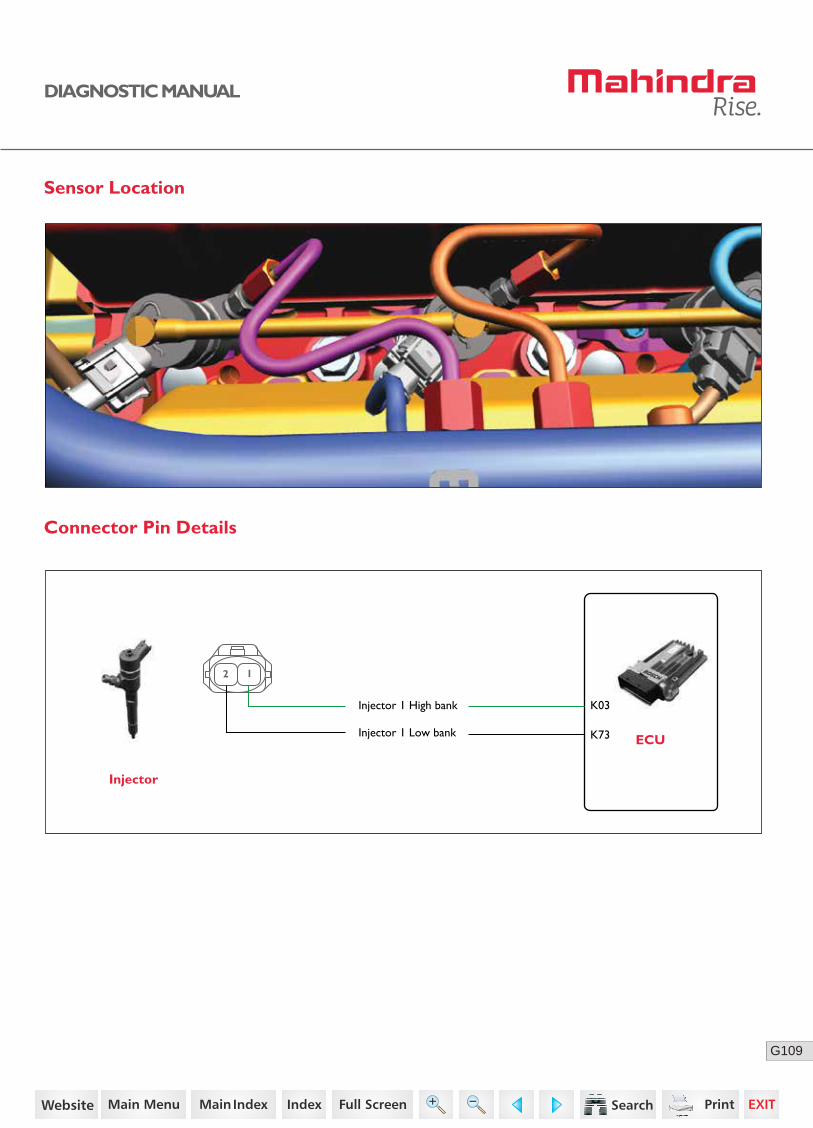
Connector Pin Details
ECU
Injector
K73
K03Injector 1 High bank
Injector 1 Low bank
2 1
Sensor Location
37https://www.truck-manuals.net/

110G
DIAGNOSTIC MANUAL
Diagnostic Procedure
2 Turn OFF the ignition switch.
Disconnect the 1st injector connector and ECU connector.
Check continuity for the following:
Go to Step 3
Go to Step 4
Acceptance Criteria
Ensure proper continuity.
Step Test Procedure Yes No
• Replace the wiring harness.
1 Check whether the 1st Injector connector is connect-ed properly.
Go to Step 2 • Ensure better connec-tions.
• ECU connector pins K03 to Injector connector pin 1
• ECU connector pins K73 to Injector connector pin 2
• Replace the injector with a new one.
3 Remove the 1st injector connector.
With the injector mounted on engine, Check the resis-tance between pin 1 and 2.
Acceptance Criteria
Normally less than 100 milli ohms.
38https://www.truck-manuals.net/

111G
DIAGNOSTIC MANUAL
NoNoStep Test Procedure Yes No
• Clear the DTC and verify using the FES diagnostic tool.
• Activate the ignition for one driving cycle (ignition-OFF and ON).
Healing Condition
After performing the troubleshooting for each P Code, follow the below test procedure before driving the vehicle.
Upon completion of diagnostic procedure, clear the DTC. Ensure that the problem has been rectified and the DTC does not appear again.
• Replace the ECU.• Clear the DTC and verify.
• If the error repeats, replace the injector with a new one.
4 Connect the ECU connector.
Turn ON the ignition switch.
Check the supply voltage between the first pin of 1stinjector connector with respect to ground.
Acceptance Criteria
12 volts for 1st injector
39https://www.truck-manuals.net/
112G
DIAGNOSTIC MANUAL
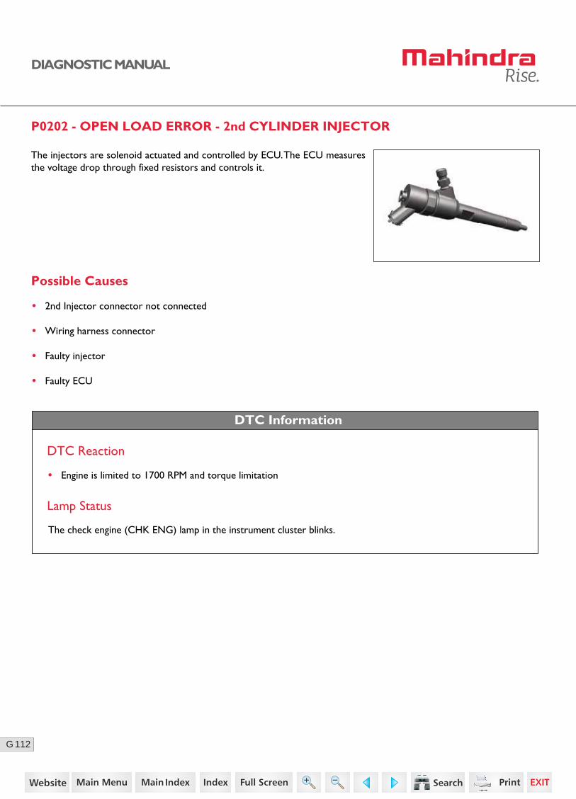
P0202 - OPEN LOAD ERROR - 2nd CYLINDER INJECTOR
DTC Information
DTC Reaction
Lamp Status
The check engine (CHK ENG) lamp in the instrument cluster blinks.
Possible Causes
• 2nd Injector connector not connected
• Wiring harness connector
• Faulty injector
• Faulty ECU
The injectors are solenoid actuated and controlled by ECU. The ECU measures the voltage drop through fixed resistors and controls it.
• Engine is limited to 1700 RPM and torque limitation
40https://www.truck-manuals.net/
113G
DIAGNOSTIC MANUAL
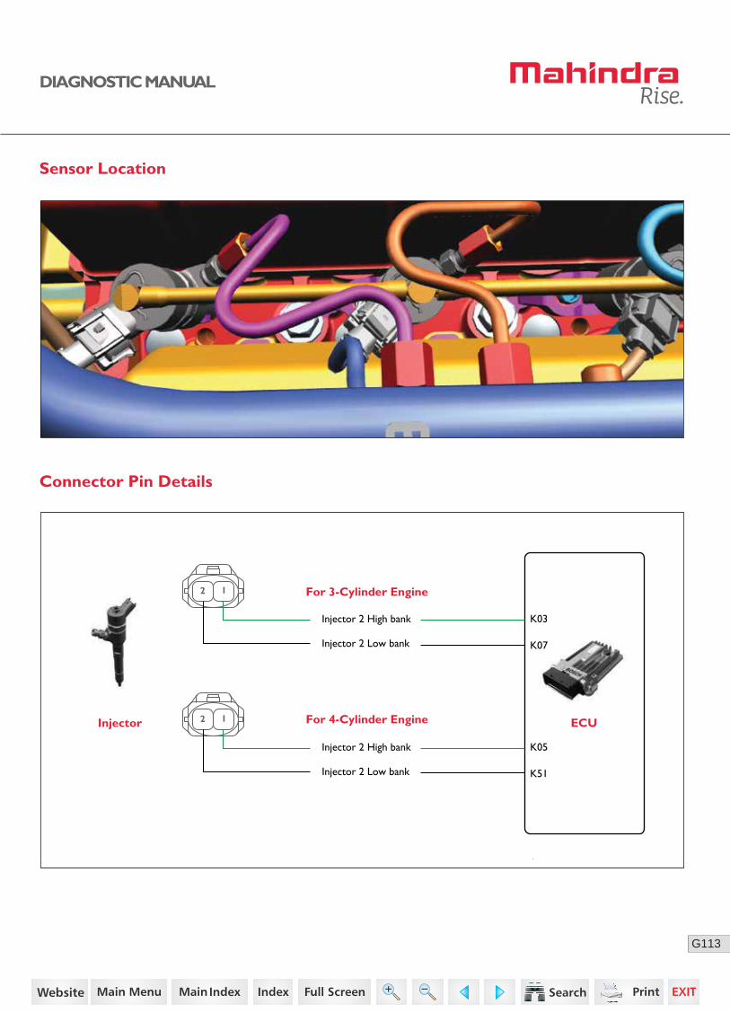
Connector Pin Details
Sensor Location
Injector For 4-Cylinder Engine
K07
K03Injector 2 High bank
Injector 2 Low bank
2 1
ECU
For 3-Cylinder Engine
K51
K05Injector 2 High bank
Injector 2 Low bank
2 1
41https://www.truck-manuals.net/
114G
DIAGNOSTIC MANUAL
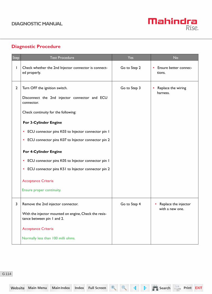
Diagnostic Procedure
2 Turn OFF the ignition switch.
Disconnect the 2nd injector connector and ECU connector.
Check continuity for the following:
Go to Step 3
Acceptance Criteria
For 3-Cylinder Engine
Ensure proper continuity.
Step Test Procedure Yes No
• Replace the wiring harness.
1 Check whether the 2nd Injector connector is connect-ed properly.
Go to Step 2 • Ensure better connec-tions.
• ECU connector pins K03 to Injector connector pin 1
• ECU connector pins K07 to Injector connector pin 2
For 4-Cylinder Engine
• ECU connector pins K05 to Injector connector pin 1
• ECU connector pins K51 to Injector connector pin 2
Go to Step 4 • Replace the injector with a new one.
3 Remove the 2nd injector connector.
With the injector mounted on engine, Check the resis-tance between pin 1 and 2.
Acceptance Criteria
Normally less than 100 milli ohms.
42https://www.truck-manuals.net/
115G
DIAGNOSTIC MANUAL
• Clear the DTC and verify using the FES diagnostic tool.
• Activate the ignition for one driving cycle (ignition-OFF and ON).
Healing Condition
After performing the troubleshooting for each P Code, follow the below test procedure before driving the vehicle.
Upon completion of diagnostic procedure, clear the DTC. Ensure that the problem has been rectified and the DTC does not appear again.
NoNoStep Test Procedure Yes No
• Replace the ECU.• Clear the DTC and verify.
• If the error repeats, replace the injector with a new one.
4 Connect the ECU connector.
Turn ON the ignition switch.
Check the supply voltage between the first pin of 2ndinjector connector with respect to ground.
Acceptance Criteria
12 volts for 2nd injector
43https://www.truck-manuals.net/
116G
DIAGNOSTIC MANUAL
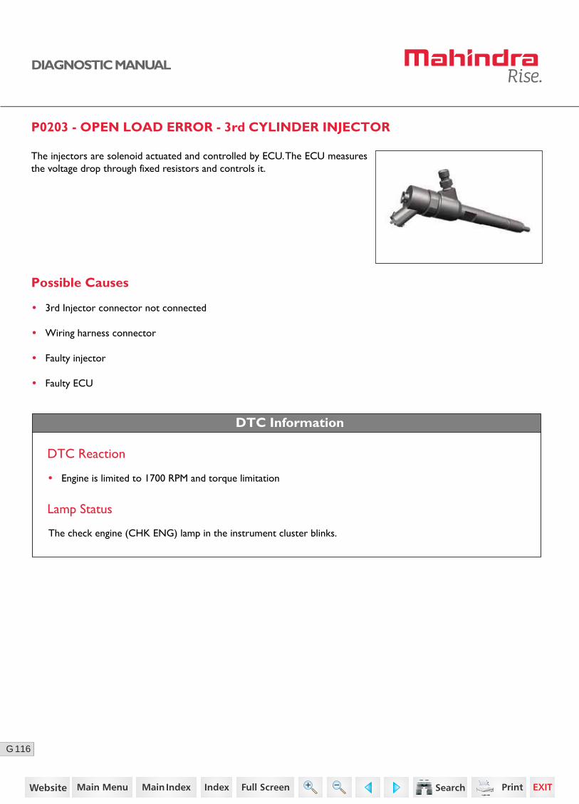
P0203 - OPEN LOAD ERROR - 3rd CYLINDER INJECTOR
The injectors are solenoid actuated and controlled by ECU. The ECU measures the voltage drop through fixed resistors and controls it.
DTC Information
DTC Reaction
• Engine is limited to 1700 RPM and torque limitation
Lamp Status
The check engine (CHK ENG) lamp in the instrument cluster blinks.
Possible Causes
• 3rd Injector connector not connected
• Wiring harness connector
• Faulty injector
• Faulty ECU
44https://www.truck-manuals.net/

117G
DIAGNOSTIC MANUAL
Sensor Location
ECU
Injector
K29
K05Injector 3 High bank
Injector 3 Low bank
2 1
Connector Pin Details
45https://www.truck-manuals.net/
118G
DIAGNOSTIC MANUAL
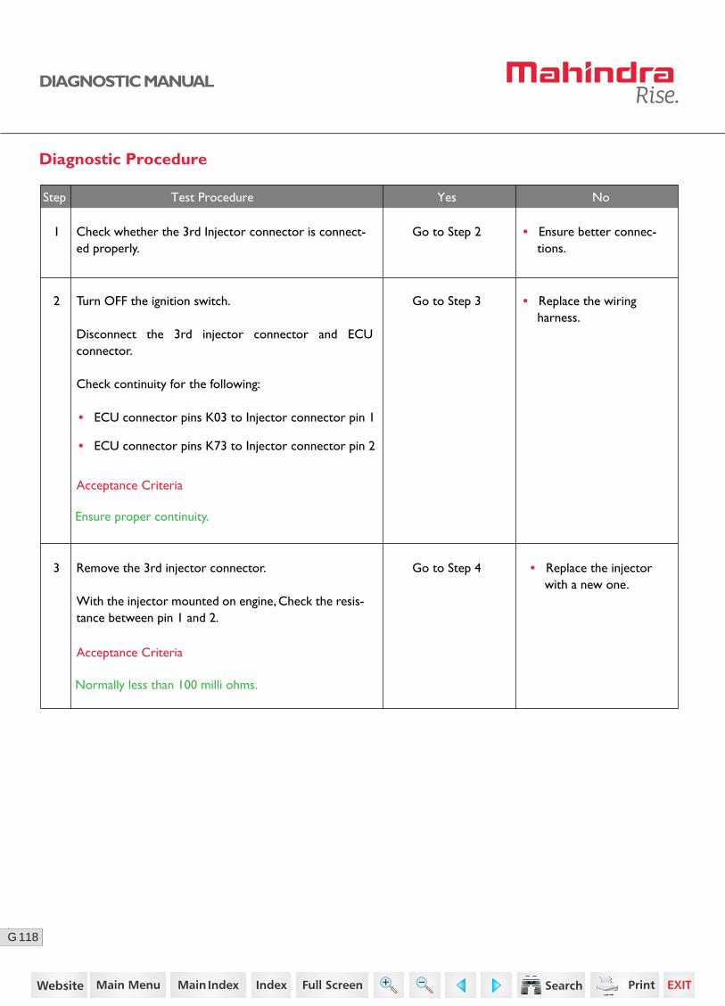
Diagnostic Procedure
2 Turn OFF the ignition switch.
Disconnect the 3rd injector connector and ECU connector.
Check continuity for the following:
Go to Step 3
Go to Step 4
Acceptance Criteria
Ensure proper continuity.
Step Test Procedure Yes No
• Replace the wiring harness.
1 Check whether the 3rd Injector connector is connect-ed properly.
Go to Step 2 • Ensure better connec-tions.
• ECU connector pins K03 to Injector connector pin 1
• ECU connector pins K73 to Injector connector pin 2
• Replace the injector with a new one.
3 Remove the 3rd injector connector.
With the injector mounted on engine, Check the resis-tance between pin 1 and 2.
Acceptance Criteria
Normally less than 100 milli ohms.
46https://www.truck-manuals.net/
119G
DIAGNOSTIC MANUAL
NoNoStep Test Procedure Yes No
• Clear the DTC and verify using the FES diagnostic tool.
• Activate the ignition for one driving cycle (ignition-OFF and ON).
Healing Condition
After performing the troubleshooting for each P Code, follow the below test procedure before driving the vehicle.
Upon completion of diagnostic procedure, clear the DTC. Ensure that the problem has been rectified and the DTC does not appear again.
• Replace the ECU.• Clear the DTC and verify.
• If the error repeats, replace the injector with a new one.
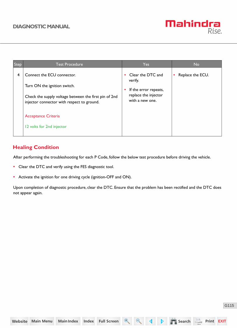
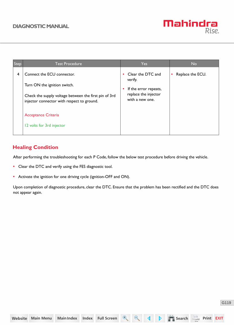
4 Connect the ECU connector.
Turn ON the ignition switch.
Check the supply voltage between the first pin of 3rdinjector connector with respect to ground.
Acceptance Criteria
12 volts for 3rd injector
47https://www.truck-manuals.net/
120G
DIAGNOSTIC MANUAL
P0219 - ENGINE OVERSPEED DETECTED
Possible Causes
• Detection of engine over speed
Description
Over-speed detection in component engine protection.
DTC Information
Lamp Status
The check engine (CHK ENG) lamp in the instrument cluster blinks.
DTC Reaction
The engine may get damaged.
Diagnostic Procedure
1. Do not downshift the gear by higher shift (e.g. from 5th gear to 2nd gear).
2. Use the exhaust brake when descending from hills.
• Clear the DTC and verify using the FES diagnostic tool.
• Activate the ignition for one driving cycle (ignition-OFF and ON).
Healing Condition
After performing the troubleshooting for each P Code, follow the below test procedure before driving the vehicle.
Upon completion of diagnostic procedure, clear the DTC. Ensure that the problem has been rectified and the DTC does not appear again.
48https://www.truck-manuals.net/

121G
DIAGNOSTIC MANUAL
P0222 - SIGNAL RANGE CHECK LOW - SECONDARY ACCELERATOR PEDAL
Possible Causes
• Loose connections
• Wiring harness problem
• Faulty accelerator pedal sensor
• Faulty ECU
Normal Operation
DTC Information
At normal vehicle condition, the ECU receives an output voltage signal (850 mV to 4.8V) from the accelerator pedal module (Secondary Sensor).
DTC Detecting Condition
The output voltage signal received from the accelerator pedal module is below 850 mV.
DTC Reaction
• Torque / Engine speed limitations
• No response from the accelerator pedal module
Lamp Status
The check engine (CHK ENG) lamp in the instrument cluster blinks.
Accelerator pedal module (APM) consists of two sensors (Primary and Second-ary) which act as a potentiometer and it’s output voltage changes according to the pedal position.
The ECU applies a reference voltage to the APM sensor and then measures the voltage that is present on the APM sensor signal circuit. The ECU uses the APM sensor signal for further calculation of fuelling and other engine operational parameters.
49https://www.truck-manuals.net/

122G
DIAGNOSTIC MANUAL
Sensor Location
Connector Pin Details
K40
K18
K83
K61Sensor 1 Signal
Primary Sensor
Secondary Sensor
Sensor 2 Signal
Sensor 1 Ground
Sensor 2 Ground
Sensor 1 SupplyAccelerator Pedal Module
ECU
Sensor 2 Supply
K82
K60
A B C D E F
50https://www.truck-manuals.net/

123G
DIAGNOSTIC MANUAL
Diagnostic Procedure
03
2
3
Turn OFF the ignition switch.
Disconnect the ECU connector and sensor wiring harness connector.
Check continuity for the following:
• ECU connector pin K61 to Sensor connector pin A
• ECU connector pin K83 to Sensor connector pin B
• ECU connector pin K18 to Sensor connector pin C
• ECU connector pin K40 to Sensor connector pin D
• ECU connector pin K82 to Sensor connector pin E
• ECU connector pin K60 to Sensor connector pin F
Turn ON the ignition with ECU connector connected.
Check the sensor connector pins B and E is shorted to battery.
And also check the sensor connector pins A, C, D and F is shorted to ground.
Go to Step 3 • Replace the wiring harness.
Acceptance Criteria
Ensure proper continuity.
Acceptance Criteria
No short circuit to ground / battery.
Step Test Procedure Yes No
1 Go to Step 2 • Ensure proper fitment.Check for the proper fitment of accelerator pedal sensor and connector.
Go to Step 4 • Replace the wiring harness.
51https://www.truck-manuals.net/

124G
DIAGNOSTIC MANUAL
• Clear the DTC and verify using the FES diagnostic tool.
• Activate the ignition for one driving cycle (ignition-OFF and ON).
Healing Condition
After performing the troubleshooting for each P Code, follow the below test procedure before driving the vehicle.
Upon completion of diagnostic procedure, clear the DTC. Ensure that the problem has been rectified and the DTC does not appear again.
Step Test Procedure Yes No
5 Turn ON the ignition with sensor wiring harness connector connected.
Press the accelerator pedal and check for any response.
Clear the DTC and verify. • Replace the sensor with a new one.
• Replace the ECU.4 Check the supply voltage between the following:
• Sensor connector pins C and B
• Sensor connector pins D and E
Go to Step 5
Acceptance Criteria
Voltage = 5V (+/- 0.25)
Acceptance Criteria
RPM varies from low idle to high idle.
52https://www.truck-manuals.net/
125G
DIAGNOSTIC MANUAL
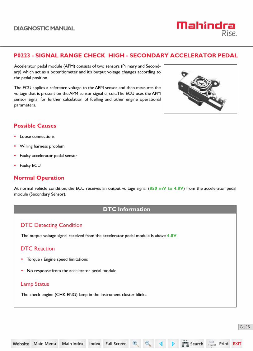
P0223 - SIGNAL RANGE CHECK HIGH - SECONDARY ACCELERATOR PEDAL
Possible Causes
• Loose connections
• Wiring harness problem
• Faulty accelerator pedal sensor
• Faulty ECU
Normal Operation
DTC Information
At normal vehicle condition, the ECU receives an output voltage signal (850 mV to 4.8V) from the accelerator pedal module (Secondary Sensor).
DTC Detecting Condition
The output voltage signal received from the accelerator pedal module is above 4.8V.
DTC Reaction
• Torque / Engine speed limitations
• No response from the accelerator pedal module
Lamp Status
The check engine (CHK ENG) lamp in the instrument cluster blinks.
Accelerator pedal module (APM) consists of two sensors (Primary and Second-ary) which act as a potentiometer and it’s output voltage changes according to the pedal position.
The ECU applies a reference voltage to the APM sensor and then measures the voltage that is present on the APM sensor signal circuit. The ECU uses the APM sensor signal for further calculation of fuelling and other engine operational parameters.
53https://www.truck-manuals.net/

126G
DIAGNOSTIC MANUAL
Sensor Location
Connector Pin Details
K40
K18
K83
K61Sensor 1 Signal
Primary Sensor
Secondary Sensor
Sensor 2 Signal
Sensor 1 Ground
Sensor 2 Ground
Sensor 1 SupplyAccelerator Pedal Module
ECU
Sensor 2 Supply
K82
K60
A B C D E F
54https://www.truck-manuals.net/
127G
DIAGNOSTIC MANUAL
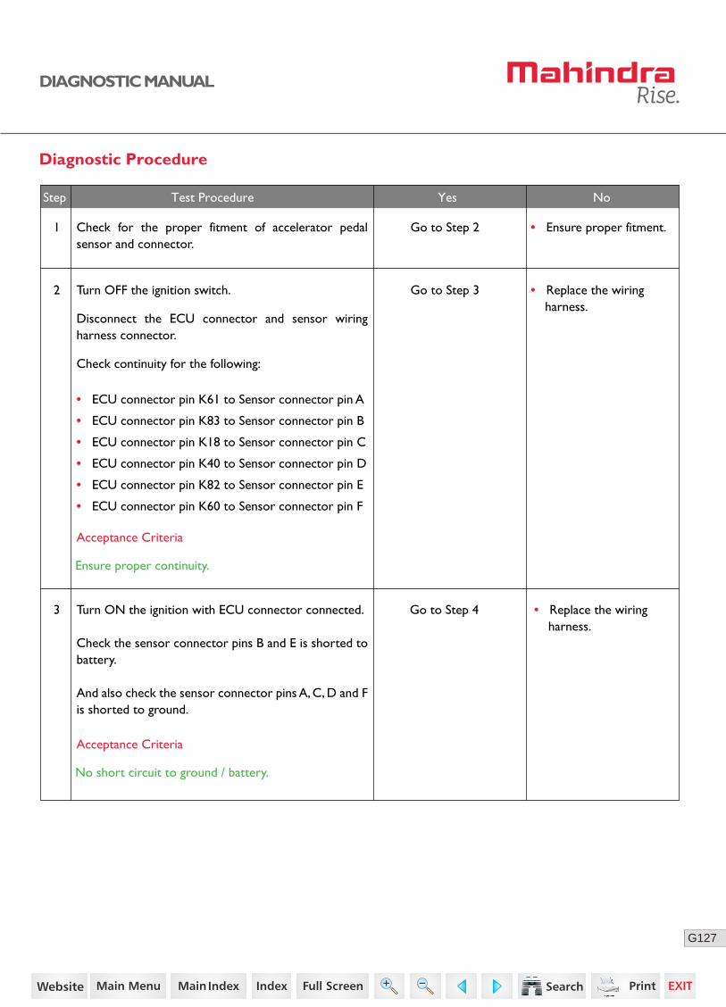
Diagnostic Procedure
03
2
3
Turn OFF the ignition switch.
Disconnect the ECU connector and sensor wiring harness connector.
Check continuity for the following:
• ECU connector pin K61 to Sensor connector pin A
• ECU connector pin K83 to Sensor connector pin B
• ECU connector pin K18 to Sensor connector pin C
• ECU connector pin K40 to Sensor connector pin D
• ECU connector pin K82 to Sensor connector pin E
• ECU connector pin K60 to Sensor connector pin F
Turn ON the ignition with ECU connector connected.
Check the sensor connector pins B and E is shorted to battery.
And also check the sensor connector pins A, C, D and F is shorted to ground.
Go to Step 3 • Replace the wiring harness.
Acceptance Criteria
Ensure proper continuity.
Acceptance Criteria
No short circuit to ground / battery.
Step Test Procedure Yes No
1 Go to Step 2 • Ensure proper fitment.Check for the proper fitment of accelerator pedal sensor and connector.
Go to Step 4 • Replace the wiring harness.
55https://www.truck-manuals.net/
128G
DIAGNOSTIC MANUAL
• Clear the DTC and verify using the FES diagnostic tool.
• Activate the ignition for one driving cycle (ignition-OFF and ON).
Healing Condition
After performing the troubleshooting for each P Code, follow the below test procedure before driving the vehicle.
Upon completion of diagnostic procedure, clear the DTC. Ensure that the problem has been rectified and the DTC does not appear again.
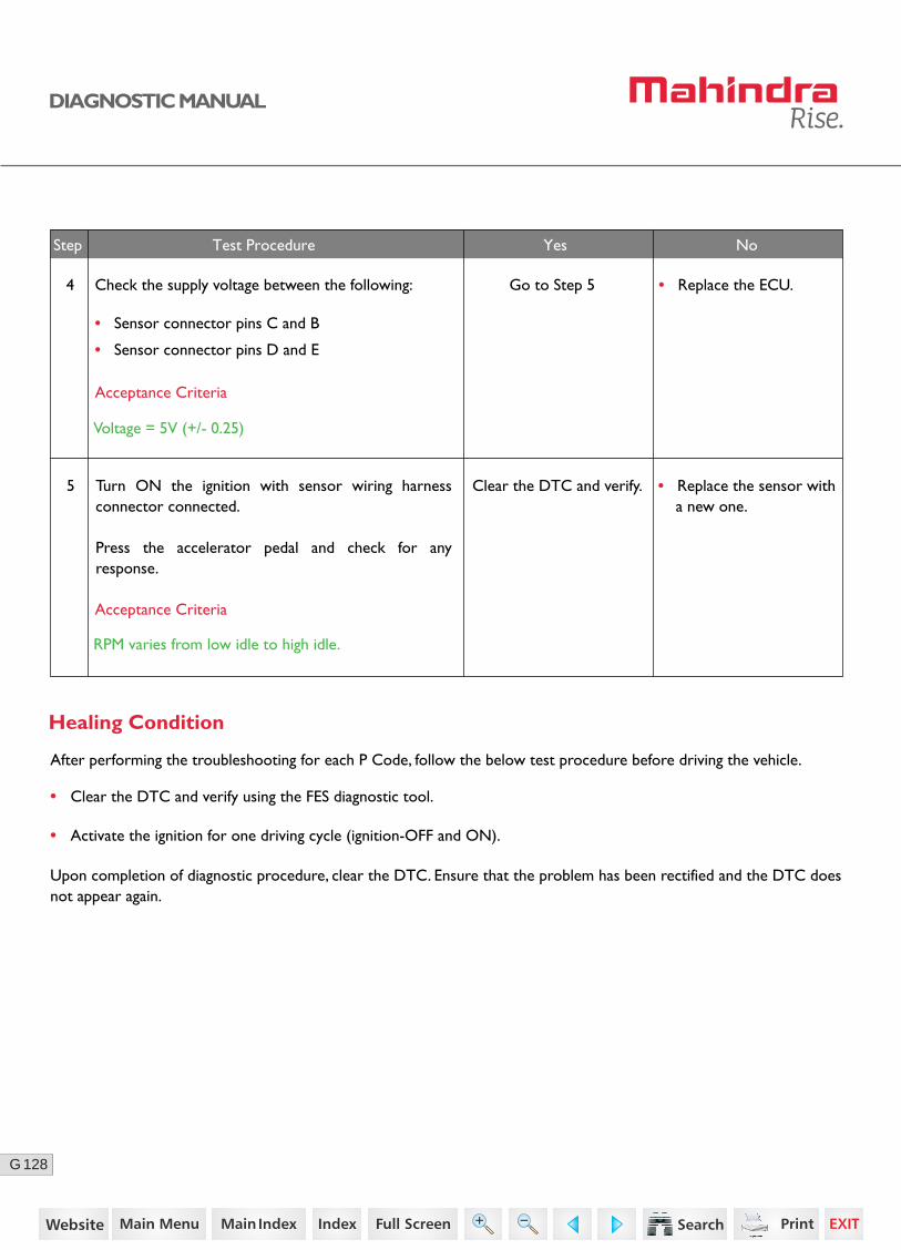
Step Test Procedure Yes No
5 Turn ON the ignition with sensor wiring harness connector connected.
Press the accelerator pedal and check for any response.
Clear the DTC and verify. • Replace the sensor with a new one.
• Replace the ECU.4 Check the supply voltage between the following:
• Sensor connector pins C and B
• Sensor connector pins D and E
Go to Step 5
Acceptance Criteria
Voltage = 5V (+/- 0.25)
Acceptance Criteria
RPM varies from low idle to high idle.
56https://www.truck-manuals.net/
129G
DIAGNOSTIC MANUAL
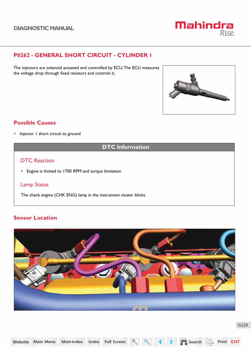
P0262 - GENERAL SHORT CIRCUIT - CYLINDER 1
Possible Causes
• Injector 1 short circuit to ground
DTC Information
DTC Reaction
• Engine is limited to 1700 RPM and torque limitation
Lamp Status
The check engine (CHK ENG) lamp in the instrument cluster blinks.
Sensor Location
The injectors are solenoid actuated and controlled by ECU. The ECU measures the voltage drop through fixed resistors and controls it.
57https://www.truck-manuals.net/
130G
DIAGNOSTIC MANUAL
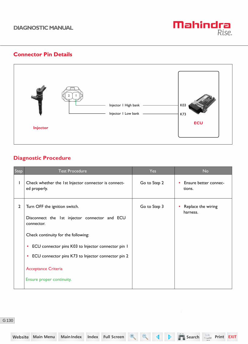
Connector Pin DetailsConnector Pin Details
ECUInjector
K73
K03Injector 1 High bank
Injector 1 Low bank
2 1
Diagnostic Procedure
2 Go to Step 3
Acceptance Criteria
Ensure proper continuity.
Step Test Procedure Yes No
• Replace the wiring harness.
1 Check whether the 1st Injector connector is connect-ed properly.
Go to Step 2 • Ensure better connec-tions.
Turn OFF the ignition switch.
Disconnect the 1st injector connector and ECU connector.
Check continuity for the following:
• ECU connector pins K03 to Injector connector pin 1
• ECU connector pins K73 to Injector connector pin 2
58https://www.truck-manuals.net/

131G
DIAGNOSTIC MANUAL
Go to Step 5
Step Test Procedure Yes No
• Replace the injector with a new one.
4 Remove the 1st injector connector.
With the injector mounted on engine, Check the resis-tance between pin 1 and 2.
Acceptance Criteria
Normally less than 100 milli ohms.
• Replace the ECU.• Clear the DTC and verify.
• If the error repeats, replace the injector with a new one.
5 Connect the ECU connector.
Turn ON the ignition switch.
Check the supply voltage between the first pin of 1stinjector connector with respect to ground.
Acceptance Criteria
12 volts for 1st injector
• Clear the DTC and verify using the FES diagnostic tool.
• Activate the ignition for one driving cycle (ignition-OFF and ON).
Healing Condition
After performing the troubleshooting for each P Code, follow the below test procedure before driving the vehicle.
Upon completion of diagnostic procedure, clear the DTC. Ensure that the problem has been rectified and the DTC does not appear again.
3 Check that the injector connector pins are not short with battery / ground.
Also check that the injector connector pins are not short with each other and with injector body.
Acceptance Criteria
No short circuit between battery positive/injector body.
• Replace the wiring harness.
Go to Step 4
59https://www.truck-manuals.net/

132G
DIAGNOSTIC MANUAL
P0265 - GENERAL SHORT CIRCUIT - CYLINDER 2
Possible Causes
• Injector 2 short circuit to ground
DTC Information
DTC Reaction
Lamp Status
The check engine (CHK ENG) lamp in the instrument cluster blinks.
Sensor Location
• Engine is limited to 1700 RPM and torque limitation
The injectors are solenoid actuated and controlled by ECU. The ECU measures the voltage drop through fixed resistors and controls it.
60https://www.truck-manuals.net/
133G
DIAGNOSTIC MANUAL
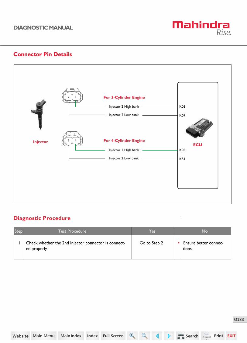
Connector Pin DetailsConnector Pin Details
Diagnostic Procedure
Step Test Procedure Yes No
1 Check whether the 2nd Injector connector is connect-ed properly.
Go to Step 2 • Ensure better connec-tions.
Injector For 4-Cylinder Engine
K07
K03Injector 2 High bank
Injector 2 Low bank
2 1
ECU
For 3-Cylinder Engine
K51
K05Injector 2 High bank
Injector 2 Low bank
2 1
61https://www.truck-manuals.net/
134G
DIAGNOSTIC MANUAL
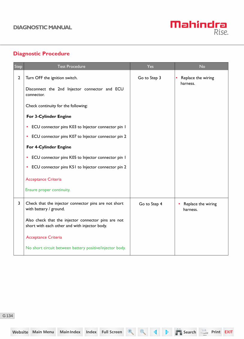
Diagnostic Procedure
Acceptance Criteria
Ensure proper continuity.
Step Test Procedure Yes No
2 Go to Step 3 • Replace the wiring harness.
Turn OFF the ignition switch.
Disconnect the 2nd Injector connector and ECU connector.
Check continuity for the following:
For 3-Cylinder Engine
• ECU connector pins K03 to Injector connector pin 1
• ECU connector pins K07 to Injector connector pin 2
For 4-Cylinder Engine
• ECU connector pins K05 to Injector connector pin 1
• ECU connector pins K51 to Injector connector pin 2
3 Check that the injector connector pins are not short with battery / ground.
Also check that the injector connector pins are not short with each other and with injector body.
Acceptance Criteria
No short circuit between battery positive/injector body.
• Replace the wiring harness.
Go to Step 4
62https://www.truck-manuals.net/
135G
DIAGNOSTIC MANUAL
NoNoStep Test Procedure Yes No
• Clear the DTC and verify using the FES diagnostic tool.
• Activate the ignition for one driving cycle (ignition-OFF and ON).
Healing Condition
After performing the troubleshooting for each P Code, follow the below test procedure before driving the vehicle.
Upon completion of diagnostic procedure, clear the DTC. Ensure that the problem has been rectified and the DTC does not appear again.
Go to Step 5 • Replace the injector with a new one.
4 Remove the 2nd injector connector.
With the injector mounted on engine, Check the resis-tance between pin 1 and 2.
Acceptance Criteria
Normally less than 100 milli ohms.
• Replace the ECU.• Clear the DTC and verify.
• If the error repeats, replace the injector with a new one.
5 Connect the ECU connector.
Turn ON the ignition switch.
Check the supply voltage between the first pin of 2ndinjector connector with respect to ground.
Acceptance Criteria
12 volts for 2nd injector
63https://www.truck-manuals.net/
136G
DIAGNOSTIC MANUAL
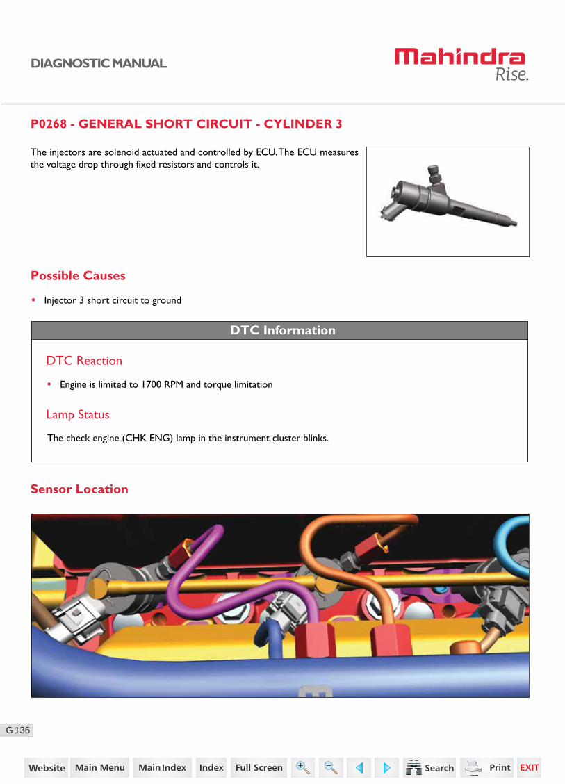
P0268 - GENERAL SHORT CIRCUIT - CYLINDER 3
Possible Causes
• Injector 3 short circuit to ground
DTC Information
DTC Reaction
Lamp Status
The check engine (CHK ENG) lamp in the instrument cluster blinks.
Sensor Location
• Engine is limited to 1700 RPM and torque limitation
The injectors are solenoid actuated and controlled by ECU. The ECU measures the voltage drop through fixed resistors and controls it.
64https://www.truck-manuals.net/
137G
DIAGNOSTIC MANUAL
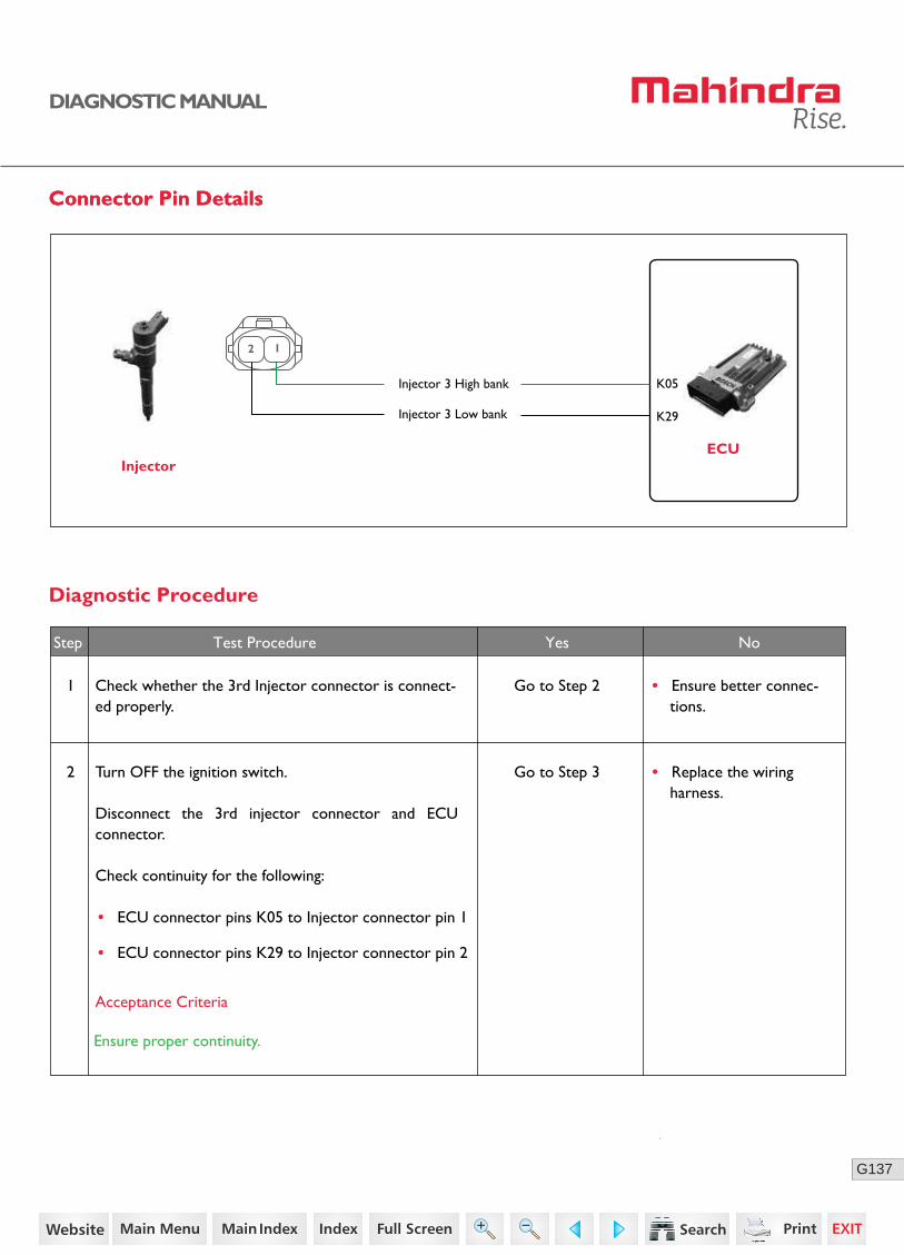
Connector Pin DetailsConnector Pin Details
ECUInjector
K29
K05Injector 3 High bank
Injector 3 Low bank
2 1
Diagnostic Procedure
2 Turn OFF the ignition switch.
Disconnect the 3rd injector connector and ECU connector.
Check continuity for the following:
Go to Step 3
Acceptance Criteria
Ensure proper continuity.
Step Test Procedure Yes No
• Replace the wiring harness.
1 Check whether the 3rd Injector connector is connect-ed properly.
Go to Step 2 • Ensure better connec-tions.
• ECU connector pins K05 to Injector connector pin 1
• ECU connector pins K29 to Injector connector pin 2
65https://www.truck-manuals.net/
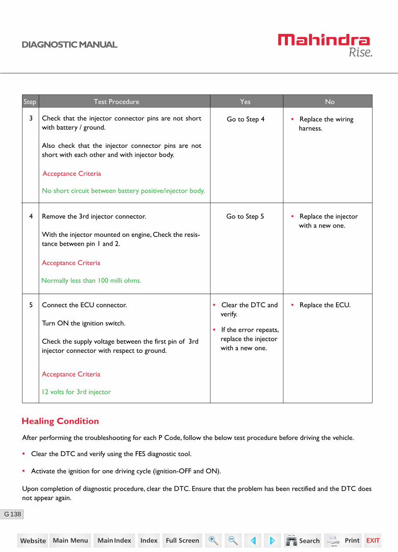
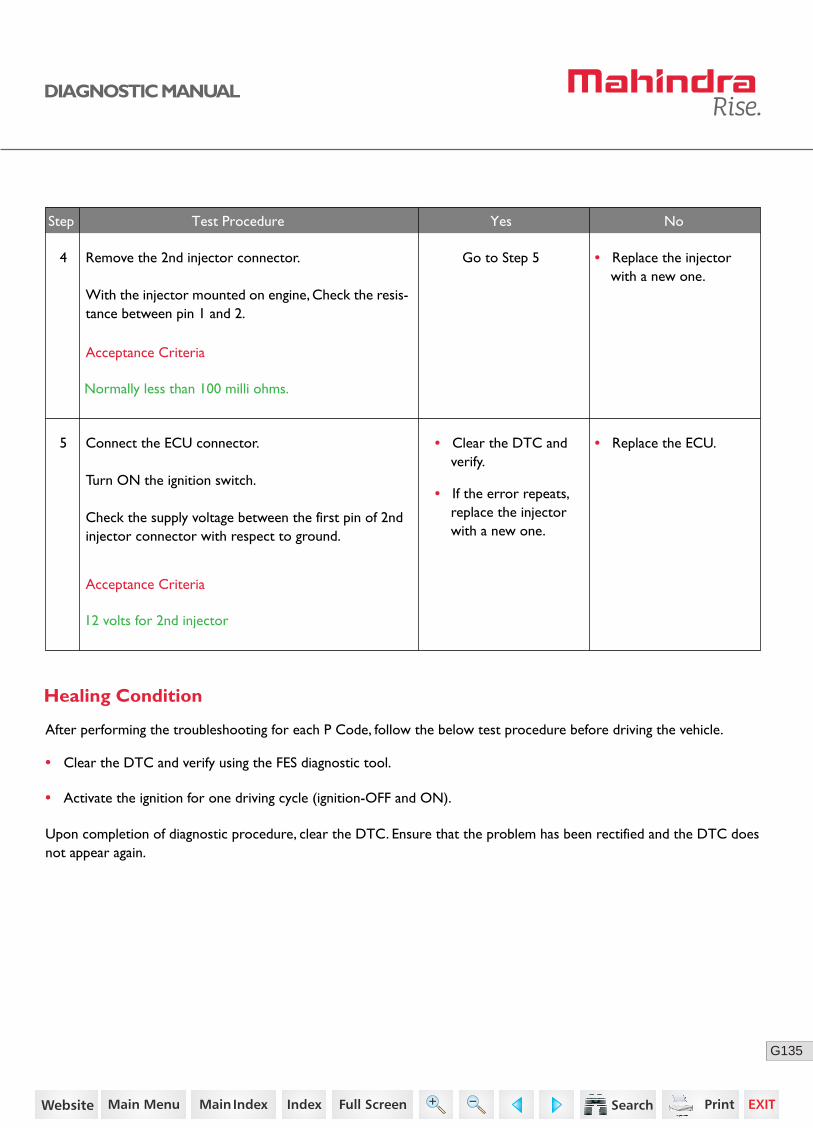
138G
DIAGNOSTIC MANUAL
Go to Step 5
Step Test Procedure Yes No
• Replace the injector with a new one.
4 Remove the 3rd injector connector.
With the injector mounted on engine, Check the resis-tance between pin 1 and 2.
Acceptance Criteria
Normally less than 100 milli ohms.
• Replace the ECU.• Clear the DTC and verify.
• If the error repeats, replace the injector with a new one.
5 Connect the ECU connector.
Turn ON the ignition switch.
Check the supply voltage between the first pin of 3rdinjector connector with respect to ground.
Acceptance Criteria
12 volts for 3rd injector
• Clear the DTC and verify using the FES diagnostic tool.
• Activate the ignition for one driving cycle (ignition-OFF and ON).
Healing Condition
After performing the troubleshooting for each P Code, follow the below test procedure before driving the vehicle.
Upon completion of diagnostic procedure, clear the DTC. Ensure that the problem has been rectified and the DTC does not appear again.
3 Check that the injector connector pins are not short with battery / ground.
Also check that the injector connector pins are not short with each other and with injector body.
Acceptance Criteria
No short circuit between battery positive/injector body.
• Replace the wiring harness.
Go to Step 4
66https://www.truck-manuals.net/
139G
DIAGNOSTIC MANUAL
P0335 - CRANKSHAFT NO SIGNAL
Possible Causes
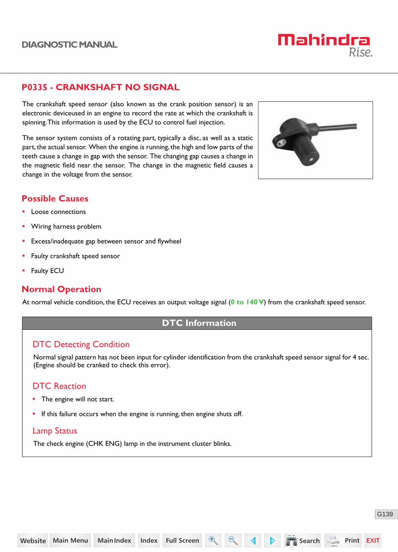
The crankshaft speed sensor (also known as the crank position sensor) is an electronic deviceused in an engine to record the rate at which the crankshaft is spinning. This information is used by the ECU to control fuel injection.
The sensor system consists of a rotating part, typically a disc, as well as a static part, the actual sensor. When the engine is running, the high and low parts of the teeth cause a change in gap with the sensor. The changing gap causes a change in the magnetic field near the sensor. The change in the magnetic field causes a change in the voltage from the sensor.
• Loose connections
• Wiring harness problem
• Excess/inadequate gap between sensor and flywheel
• Faulty crankshaft speed sensor
• Faulty ECU
Normal Operation
DTC Information
At normal vehicle condition, the ECU receives an output voltage signal (0 to 140 V) from the crankshaft speed sensor.
DTC Detecting ConditionNormal signal pattern has not been input for cylinder identification from the crankshaft speed sensor signal for 4 sec.(Engine should be cranked to check this error).
DTC Reaction
Lamp StatusThe check engine (CHK ENG) lamp in the instrument cluster blinks.
• The engine will not start.
• If this failure occurs when the engine is running, then engine shuts off.
67https://www.truck-manuals.net/
140G
DIAGNOSTIC MANUAL
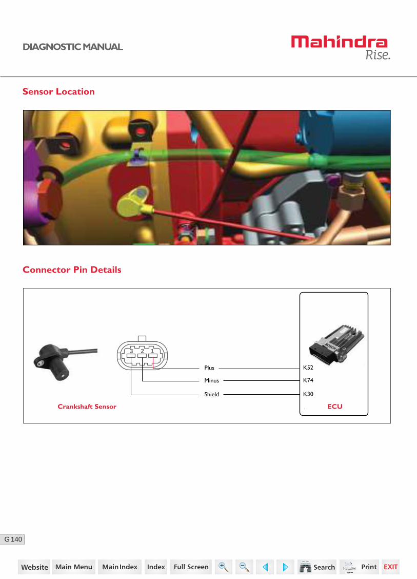
Sensor Location
Connector Pin Details
Crankshaft Sensor ECU
K52Plus
K74Minus
K30Shield
3 12
68https://www.truck-manuals.net/
141G
DIAGNOSTIC MANUAL
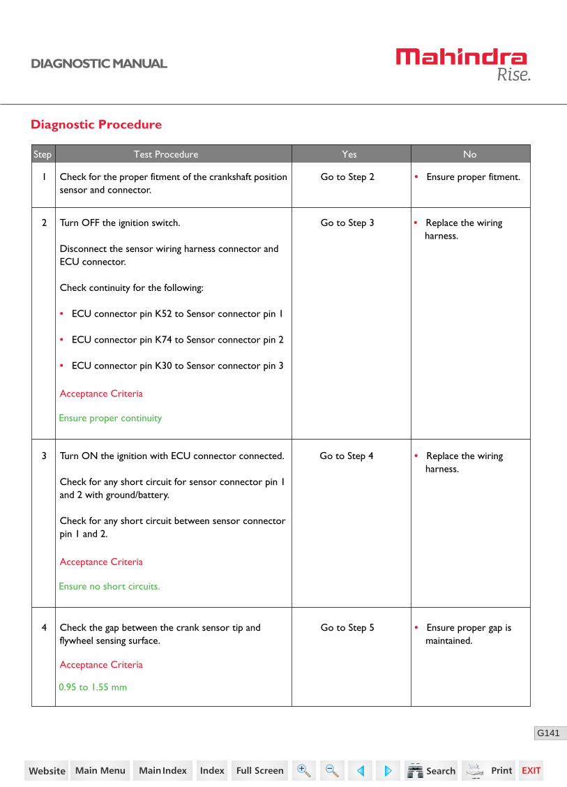
Diagnostic Procedure
1 Check for the proper fitment of the crankshaft position sensor and connector.
Go to Step 2 • Ensure proper fitment.
2 Turn OFF the ignition switch.
Disconnect the sensor wiring harness connector and ECU connector.
Check continuity for the following:
• ECU connector pin K52 to Sensor connector pin 1
• ECU connector pin K74 to Sensor connector pin 2
• ECU connector pin K30 to Sensor connector pin 3
Go to Step 3
• Replace the wiring harness.
3 Turn ON the ignition with ECU connector connected.
Check for any short circuit for sensor connector pin 1 and 2 with ground/battery.
Check for any short circuit between sensor connector pin 1 and 2.
Go to Step 4
Acceptance Criteria
Ensure proper continuity
Acceptance Criteria
Ensure no short circuits.
• Ensure proper gap is maintained.
4 Check the gap between the crank sensor tip andflywheel sensing surface.
Go to Step 5
Acceptance Criteria
0.95 to 1.55 mm
Step Test Procedure Yes No
• Replace the wiring harness.
69https://www.truck-manuals.net/
142G
DIAGNOSTIC MANUAL
No
• Clear the DTC and verify using the FES diagnostic tool.
• Activate the ignition for one driving cycle (ignition-OFF and ON).
Healing Condition
After performing the troubleshooting for each P Code, follow the below test procedure before driving the vehicle.
Upon completion of diagnostic procedure, clear the DTC. Ensure that the problem has been rectified and the DTC does not appear again.
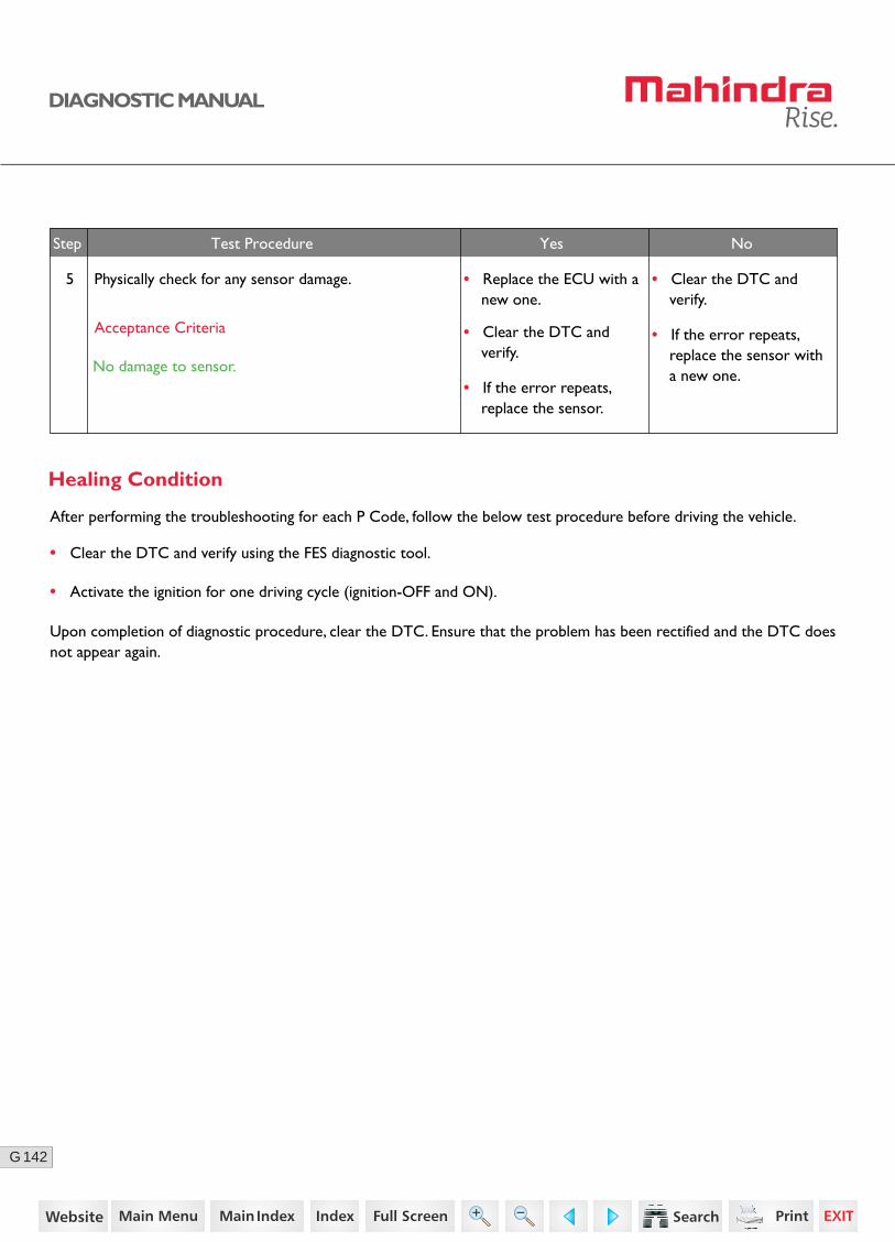
5 Physically check for any sensor damage.
Step Test Procedure Yes No
• Replace the ECU with a new one.
• Clear the DTC and verify.
• If the error repeats, replace the sensor with a new one.
• Clear the DTC and verify.
• If the error repeats, replace the sensor.
Acceptance Criteria
No damage to sensor.
70https://www.truck-manuals.net/
143G
DIAGNOSTIC MANUAL
P0339 - CRANKSHAFT ERROR SIGNAL
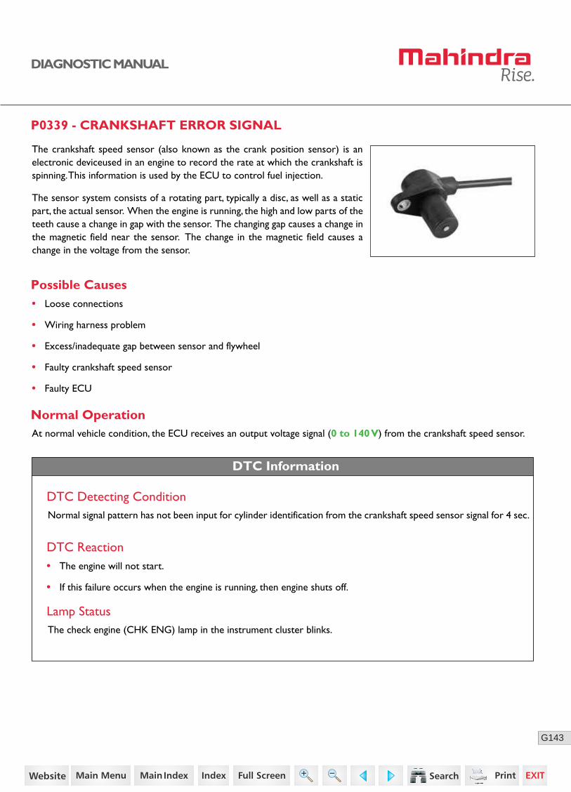
The crankshaft speed sensor (also known as the crank position sensor) is an electronic deviceused in an engine to record the rate at which the crankshaft is spinning. This information is used by the ECU to control fuel injection.
The sensor system consists of a rotating part, typically a disc, as well as a static part, the actual sensor. When the engine is running, the high and low parts of the teeth cause a change in gap with the sensor. The changing gap causes a change in the magnetic field near the sensor. The change in the magnetic field causes a change in the voltage from the sensor.
DTC Information
DTC Detecting ConditionNormal signal pattern has not been input for cylinder identification from the crankshaft speed sensor signal for 4 sec.
Possible Causes• Loose connections
• Wiring harness problem
• Excess/inadequate gap between sensor and flywheel
• Faulty crankshaft speed sensor
• Faulty ECU
Normal OperationAt normal vehicle condition, the ECU receives an output voltage signal (0 to 140 V) from the crankshaft speed sensor.
DTC Reaction
Lamp StatusThe check engine (CHK ENG) lamp in the instrument cluster blinks.
• The engine will not start.
• If this failure occurs when the engine is running, then engine shuts off.
71https://www.truck-manuals.net/

144G
DIAGNOSTIC MANUAL
Sensor Location
Connector Pin Details
Crankshaft Sensor ECU
K52Plus
K74Minus
K30Shield
3 12
72https://www.truck-manuals.net/

145G
DIAGNOSTIC MANUAL
Diagnostic Procedure
1 Check for the proper fitment of the crankshaft position sensor and connector.
Go to Step 2 • Ensure proper fitment.
2 Turn OFF the ignition switch.
Disconnect the sensor wiring harness connector and ECU connector.
Check continuity for the following:
• ECU connector pin K52 to Sensor connector pin 1
• ECU connector pin K74 to Sensor connector pin 2
• ECU connector pin K30 to Sensor connector pin 3
Go to Step 3
• Replace the wiring harness.
3 Turn ON the ignition with ECU connector connected.
Check for any short circuit for sensor connector pin 1 and 2 with ground/battery.
Check for any short circuit between sensor connector pin 1 and 2.
Go to Step 4
Acceptance Criteria
Ensure proper continuity
Acceptance Criteria
Ensure no short circuits.
• Ensure proper gap is maintained.
4 Check the gap between the crank sensor tip andflywheel sensing surface.
Go to Step 5
Acceptance Criteria
0.95 to 1.55 mm
Step Test Procedure Yes No
• Replace the wiring harness.
73https://www.truck-manuals.net/

146G
DIAGNOSTIC MANUAL
No
• Clear the DTC and verify using the FES diagnostic tool.
• Activate the ignition for one driving cycle (ignition-OFF and ON).
Healing Condition
After performing the troubleshooting for each P Code, follow the below test procedure before driving the vehicle.
Upon completion of diagnostic procedure, clear the DTC. Ensure that the problem has been rectified and the DTC does not appear again.
5 Physically check for any sensor damage.
Step Test Procedure Yes No
• Replace the ECU with a new one.
• Clear the DTC and verify.
• If the error repeats, replace the sensor with a new one.
• Clear the DTC and verify.
• If the error repeats, replace the sensor.
Acceptance Criteria
No damage to sensor.
74https://www.truck-manuals.net/
147G
DIAGNOSTIC MANUAL
P0340 - CAMSHAFT NO SIGNAL
Possible Causes
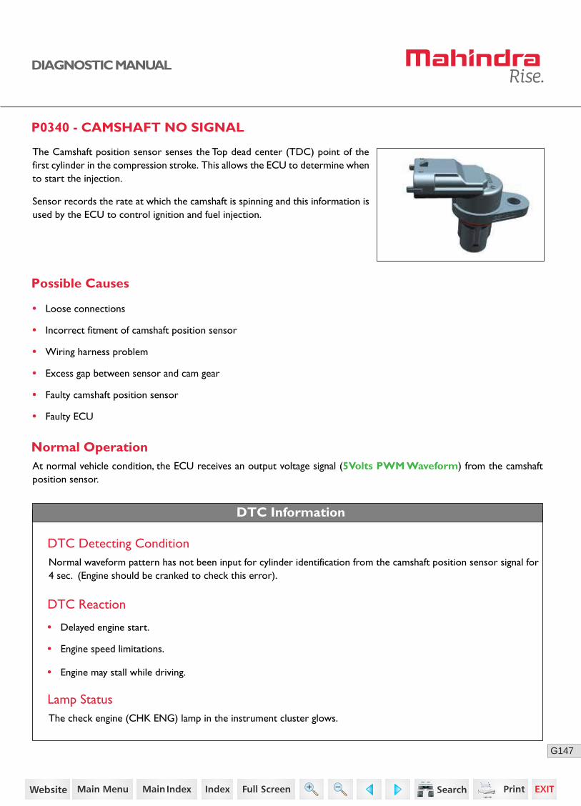
The Camshaft position sensor senses the Top dead center (TDC) point of the first cylinder in the compression stroke. This allows the ECU to determine when to start the injection.
Sensor records the rate at which the camshaft is spinning and this information is used by the ECU to control ignition and fuel injection.
• Loose connections
• Incorrect fitment of camshaft position sensor
• Wiring harness problem
• Excess gap between sensor and cam gear
• Faulty camshaft position sensor
• Faulty ECU
Normal Operation
DTC Information
At normal vehicle condition, the ECU receives an output voltage signal (5Volts PWM Waveform) from the camshaft position sensor.
DTC Detecting ConditionNormal waveform pattern has not been input for cylinder identification from the camshaft position sensor signal for 4 sec. (Engine should be cranked to check this error).
DTC Reaction
Lamp StatusThe check engine (CHK ENG) lamp in the instrument cluster glows.
• Delayed engine start.
• Engine speed limitations.
• Engine may stall while driving.
75https://www.truck-manuals.net/
148G
3 2 1
DIAGNOSTIC MANUAL
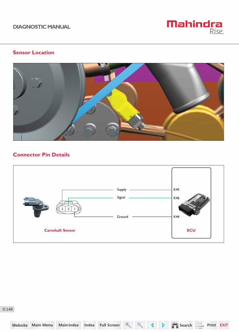
Sensor Location
Connector Pin Details
Camshaft Sensor ECU
K46
K45Supply
Ground
Signal
K44
76https://www.truck-manuals.net/
149G
DIAGNOSTIC MANUAL
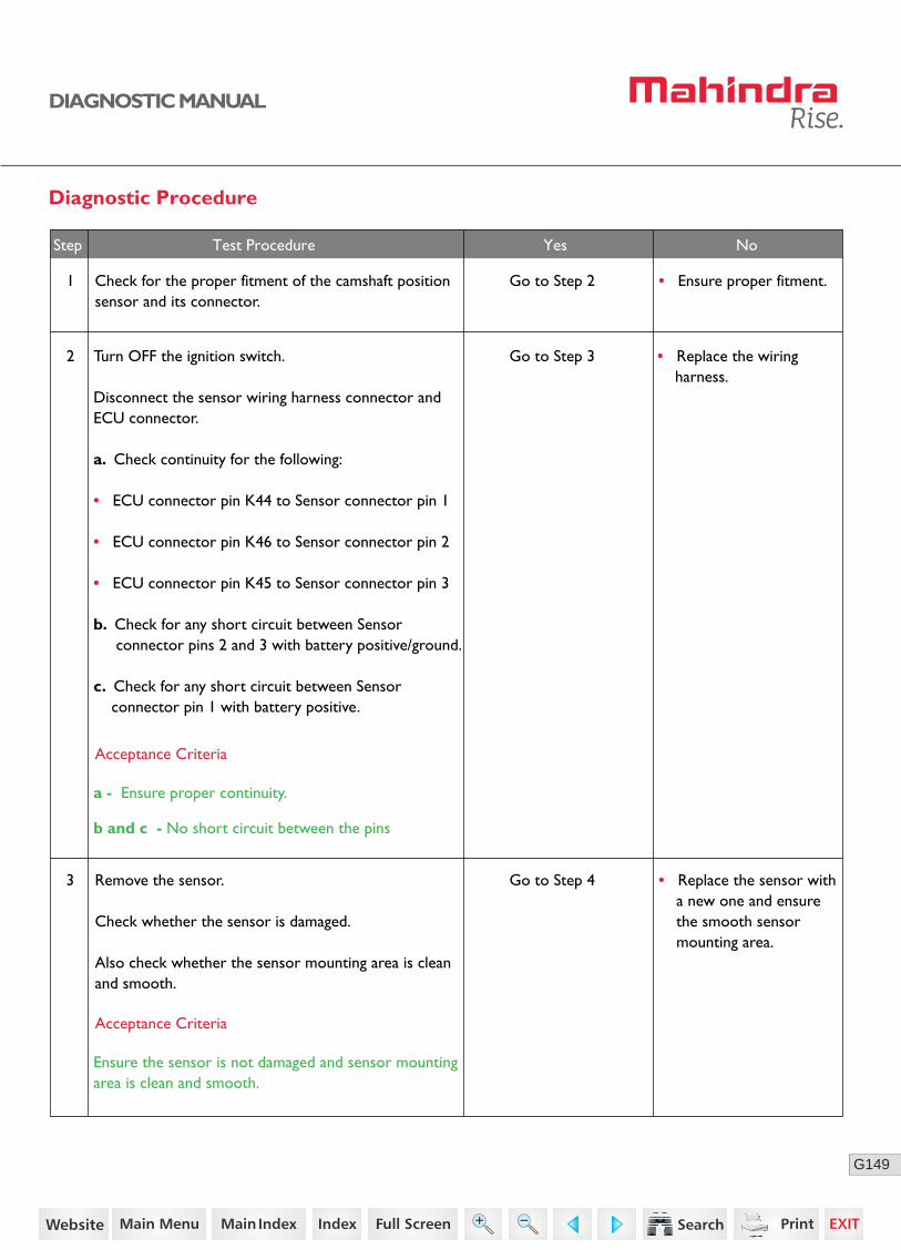
Diagnostic Procedure
1 Check for the proper fitment of the camshaft position sensor and its connector.
Go to Step 2 • Ensure proper fitment.
2 Turn OFF the ignition switch.
Disconnect the sensor wiring harness connector and ECU connector.
a. Check continuity for the following:
• ECU connector pin K44 to Sensor connector pin 1
• ECU connector pin K46 to Sensor connector pin 2
• ECU connector pin K45 to Sensor connector pin 3
b. Check for any short circuit between Sensor connector pins 2 and 3 with battery positive/ground.
c. Check for any short circuit between Sensor connector pin 1 with battery positive.
Go to Step 3
• Replace the sensor with a new one and ensure the smooth sensor mounting area.
3 Remove the sensor.
Check whether the sensor is damaged.
Also check whether the sensor mounting area is clean and smooth.
Go to Step 4
Acceptance Criteria
a - Ensure proper continuity.
b and c - No short circuit between the pins
Acceptance Criteria
Ensure the sensor is not damaged and sensor mounting area is clean and smooth.
Step Test Procedure Yes No
• Replace the wiring harness.
77https://www.truck-manuals.net/

150G
DIAGNOSTIC MANUAL
• Clear the DTC and verify using the FES diagnostic tool.
• Activate the ignition for one driving cycle (ignition-OFF and ON).
Healing Condition
After performing the troubleshooting for each P Code, follow the below test procedure before driving the vehicle.
Upon completion of diagnostic procedure, clear the DTC. Ensure that the problem has been rectified and the DTC does not appear again.
5 If the problem persist,
Replace the sensor with a new one.
Clear the DTC and verify.
If still error repeats,
Replace the ECU with a new one.
• Ensure proper gap is maintained between sensor tip and cam gear.
4 Check if the gap between the cam sensor tip and cam gear sensing surface.
Go to Step 5
Acceptance Criteria
0.1 to 2.8 mm
Step Test Procedure Yes No
78https://www.truck-manuals.net/
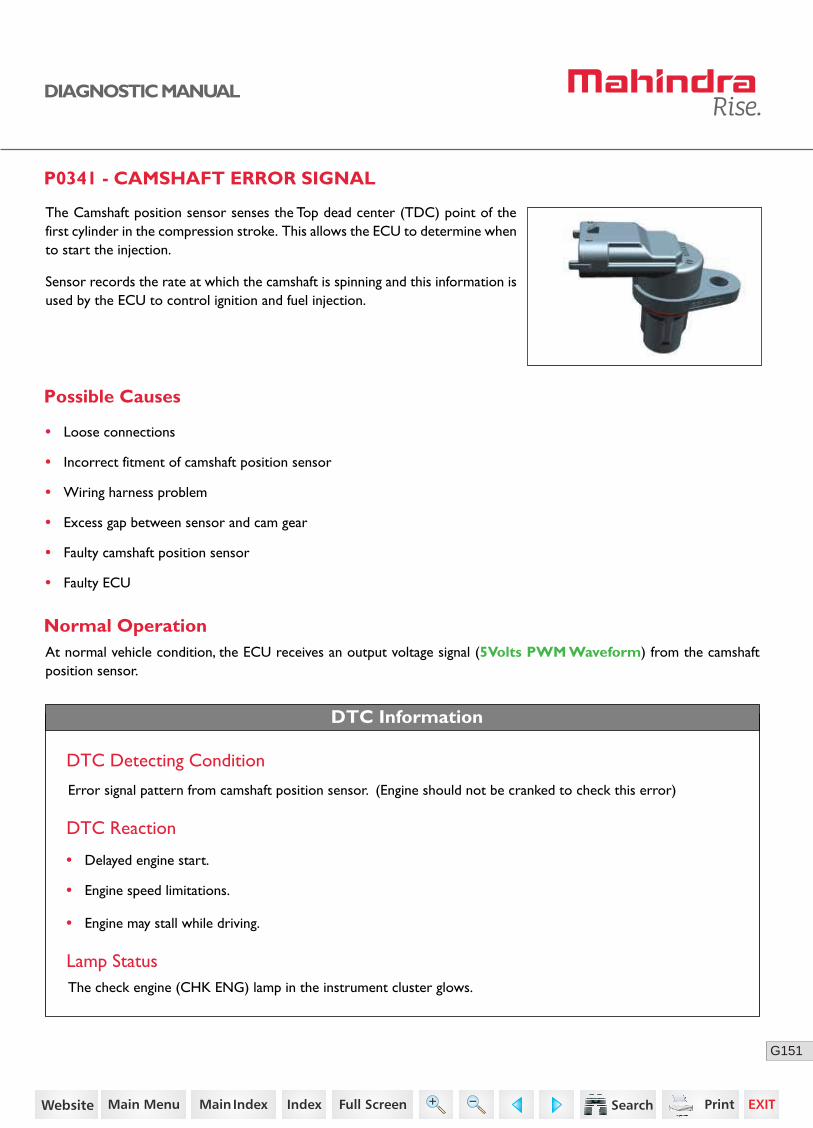
151G
DIAGNOSTIC MANUAL
P0341 - CAMSHAFT ERROR SIGNAL
The Camshaft position sensor senses the Top dead center (TDC) point of the first cylinder in the compression stroke. This allows the ECU to determine when to start the injection.
Sensor records the rate at which the camshaft is spinning and this information is used by the ECU to control ignition and fuel injection.
Error signal pattern from camshaft position sensor. (Engine should not be cranked to check this error)
Possible Causes
• Loose connections
• Incorrect fitment of camshaft position sensor
• Wiring harness problem
• Excess gap between sensor and cam gear
• Faulty camshaft position sensor
• Faulty ECU
Normal Operation
DTC Information
At normal vehicle condition, the ECU receives an output voltage signal (5Volts PWM Waveform) from the camshaft position sensor.
DTC Detecting Condition
DTC Reaction
Lamp StatusThe check engine (CHK ENG) lamp in the instrument cluster glows.
• Delayed engine start.
• Engine speed limitations.
• Engine may stall while driving.
79https://www.truck-manuals.net/

152G
3 2 1
DIAGNOSTIC MANUAL
Sensor Location
Connector Pin Details
Camshaft Sensor ECU
K46
K45Supply
Ground
Signal
K44
80https://www.truck-manuals.net/

153G
DIAGNOSTIC MANUAL
Diagnostic Procedure
1 Go to Step 2 • Ensure proper fitment.
• Replace the ECU.
2 Turn OFF the ignition switch.
Disconnect the sensor wiring harness connector and ECU connector.
Check continuity for the following:
• ECU connector pin K44 to Sensor connector pin 1
• ECU connector pin K46 to Sensor connector pin 2
• ECU connector pin K45 to Sensor connector pin 3
Check for any short circuit between sensor connec-tor pins 2 and 3 with battery positive/ground.
Check for any short circuit between sensor connec-tor pin 1 with battery positive.
Go to Step 3
4 Connect the ECU connector.
Turn ON the ignition switch.
Check the voltage between sensor connector pin 1 and 3.
3
Go to Step 5
• Replace the wiring harness.
Go to Step 4
Acceptance Criteria
Ensure proper continuity.
Acceptance Criteria
Voltage = 5V (+/- 0.25)
Acceptance Criteria
No short circuit between ground / battery positive.
Step Test Procedure Yes No
• Replace the wiring harness.
Check for the proper fitment of the camshaft position sensor and its connector.
81https://www.truck-manuals.net/
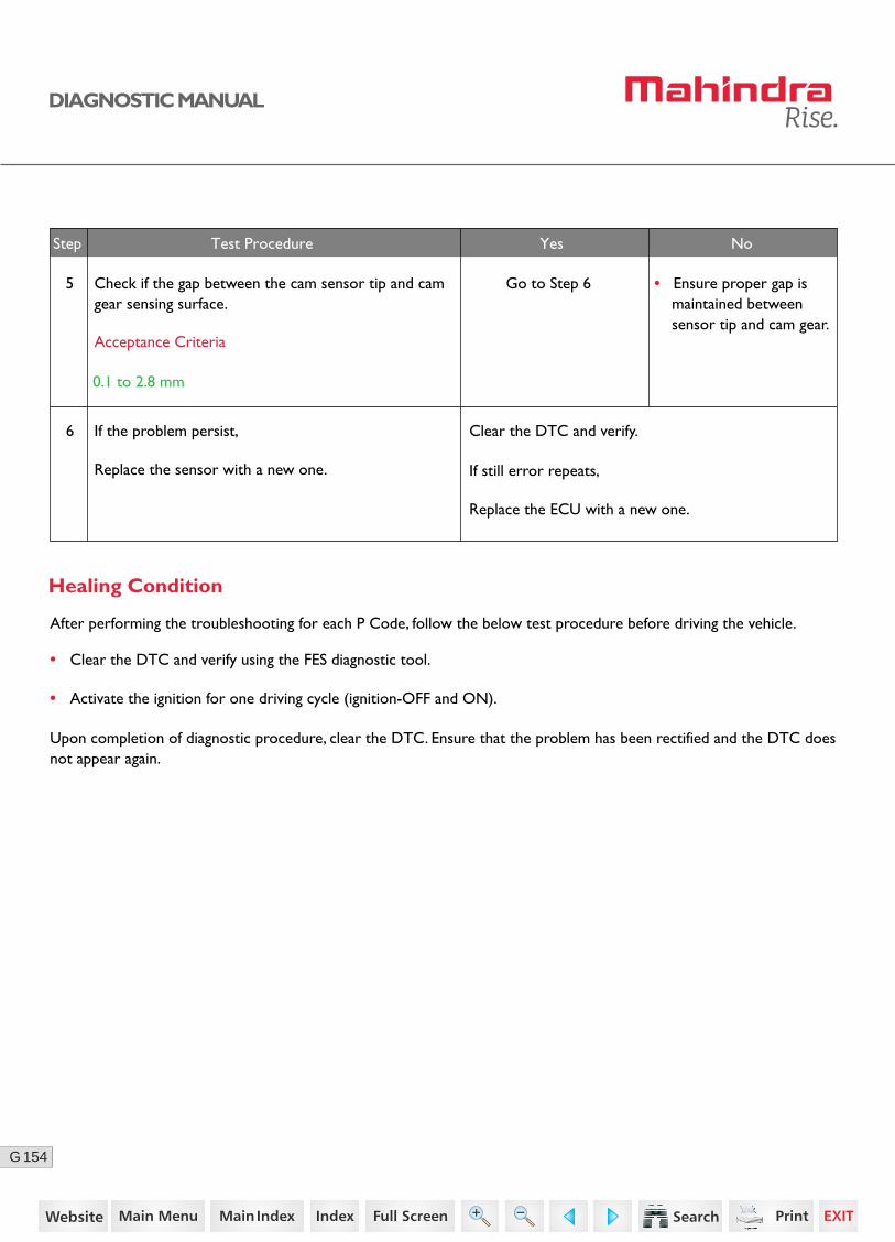
154G
DIAGNOSTIC MANUAL
• Clear the DTC and verify using the FES diagnostic tool.
• Activate the ignition for one driving cycle (ignition-OFF and ON).
Healing Condition
After performing the troubleshooting for each P Code, follow the below test procedure before driving the vehicle.
Upon completion of diagnostic procedure, clear the DTC. Ensure that the problem has been rectified and the DTC does not appear again.
6 If the problem persist,
Replace the sensor with a new one.
Clear the DTC and verify.
If still error repeats,
Replace the ECU with a new one.
• Ensure proper gap is maintained between sensor tip and cam gear.
5 Check if the gap between the cam sensor tip and cam gear sensing surface.
Go to Step 6
Acceptance Criteria
0.1 to 2.8 mm
Step Test Procedure Yes No
82https://www.truck-manuals.net/
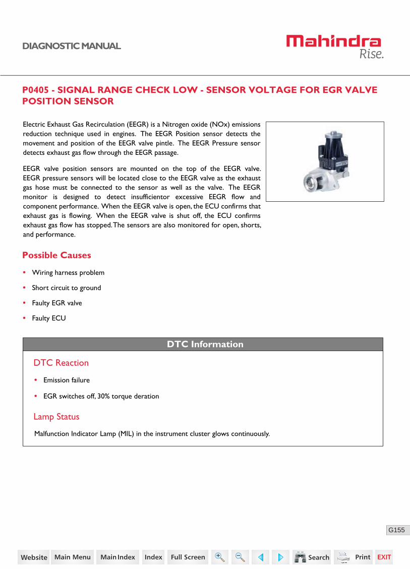
155G
DIAGNOSTIC MANUAL
P0405 - SIGNAL RANGE CHECK LOW - SENSOR VOLTAGE FOR EGR VALVE POSITION SENSOR
Possible Causes
Electric Exhaust Gas Recirculation (EEGR) is a Nitrogen oxide (NOx) emissions reduction technique used in engines. The EEGR Position sensor detects the movement and position of the EEGR valve pintle. The EEGR Pressure sensor detects exhaust gas flow through the EEGR passage.
EEGR valve position sensors are mounted on the top of the EEGR valve. EEGR pressure sensors will be located close to the EEGR valve as the exhaust gas hose must be connected to the sensor as well as the valve. The EEGR monitor is designed to detect insufficientor excessive EEGR flow and component performance. When the EEGR valve is open, the ECU confirms that exhaust gas is flowing. When the EEGR valve is shut off, the ECU confirms exhaust gas flow has stopped. The sensors are also monitored for open, shorts, and performance.
• Wiring harness problem
• Short circuit to ground
• Faulty EGR valve
• Faulty ECU
DTC Information
DTC Reaction
• Emission failure
• EGR switches off, 30% torque deration
Lamp Status
Malfunction Indicator Lamp (MIL) in the instrument cluster glows continuously.
83https://www.truck-manuals.net/

156G
DIAGNOSTIC MANUAL
Sensor Location
Connector Pin Details
EGR Valve ECUK85
K37
K58
K15EEGR position sensor - Supply
EEGR actuator motor - Positive
EEGR position sensor - Signal
EEGR position sensor - Ground
EEGR actuator motor - Negative
K84
84https://www.truck-manuals.net/

157G
DIAGNOSTIC MANUAL
Diagnostic Procedure
2 Turn OFF the ignition switch.
Disconnect the EGR and ECU connector.
Check continuity for the following:
• ECU connector pin K84 to EGR connector pin 1
• ECU connector pin K37 to EGR connector pin 2
• ECU connector pin K58 to EGR connector pin 4
• ECU connector pin K85 to EGR connector pin 5
• ECU connector pin K15 to EGR connector pin 6
Go to Step 3
Go to Step 4
Go to Step 5
• Replace the wiring harness.
4 Turn ON the ignition with ECU connector connected.
Check the supply voltage between EGR Connector pin 1 and 5.
3 Check the sensor supply line (pin no. 6), EGR motor +ve (pin no. 1), EGR motor -ve (pin no.5) and EGR position sensor (pin no. 2) is short circuited to ground/battery positive.
Acceptance Criteria
Acceptance Criteria
Voltage = 5 ± 0.2V
Acceptance Criteria
No short circuit to ground/battery positive.
Step Test Procedure Yes No
• Replace the wiring harness.
Ensure proper continuity.
1 Go to Step 2 • Ensure proper fitment.Check for the proper fitment of EGR valve and connec-tor.
• Replace the ECU.
85https://www.truck-manuals.net/

158G
DIAGNOSTIC MANUAL
• Clear the DTC and verify using the FES diagnostic tool.
• Activate the ignition for one driving cycle (ignition-OFF and ON).
After performing the troubleshooting for each P Code, follow the below test procedure before driving the vehicle.
Upon completion of diagnostic procedure, clear the DTC. Ensure that the problem has been rectified and the DTC does not appear again.
Healing Condition
Step Test Procedure Further Action
5Clear the DTC and verify.
If still error repeats,
Replace the EGR with a new one.
86https://www.truck-manuals.net/

159G
DIAGNOSTIC MANUAL
P0406 - SIGNAL RANGE CHECK HIGH - SENSOR VOLTAGE FOR EGR VALVE POSITION SENSOR
Possible Causes
Electric Exhaust Gas Recirculation (EEGR) is a Nitrogen oxide (NOx) emissions reduction technique used in engines. The EEGR Position sensor detects the movement and position of the EEGR valve pintle. The EEGR Pressure sensor detects exhaust gas flow through the EEGR passage.
EEGR valve position sensors are mounted on the top of the EEGR valve. EEGR pressure sensors will be located close to the EEGR valve as the exhaust gas hose must be connected to the sensor as well as the valve. The EEGR monitor is designed to detect insufficientor excessive EEGR flow and component performance. When the EEGR valve is open, the ECU confirms that exhaust gas is flowing. When the EEGR valve is shut off, the ECU confirms exhaust gas flow has stopped. The sensors are also monitored for open, shorts, and performance.
• Wiring harness problem
• Short circuit to ground
• Faulty EGR valve
• Faulty ECU
DTC Information
DTC Reaction
• Emission failure
• EGR switches off, 30% torque deration
Lamp Status
Malfunction Indicator Lamp (MIL) in the instrument cluster glows continuously.
87https://www.truck-manuals.net/
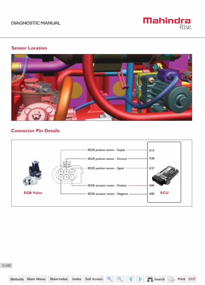
160G
DIAGNOSTIC MANUAL
02
Sensor Location
Connector Pin Details
EGR Valve ECUK85
K37
K58
K15EEGR position sensor - Supply
EEGR actuator motor - Positive
EEGR position sensor - Signal
EEGR position sensor - Ground
EEGR actuator motor - Negative
K84
88https://www.truck-manuals.net/
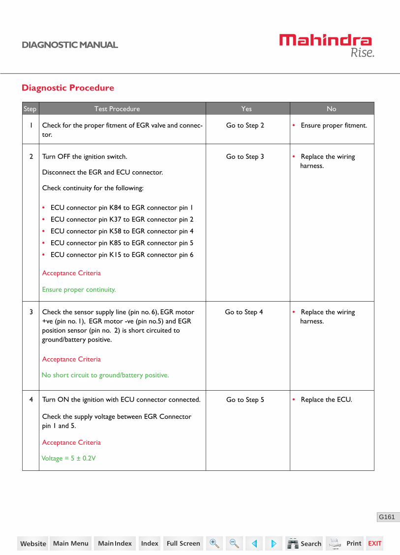
161G
DIAGNOSTIC MANUAL
Diagnostic Procedure
2 Turn OFF the ignition switch.
Disconnect the EGR and ECU connector.
Check continuity for the following:
• ECU connector pin K84 to EGR connector pin 1
• ECU connector pin K37 to EGR connector pin 2
• ECU connector pin K58 to EGR connector pin 4
• ECU connector pin K85 to EGR connector pin 5
• ECU connector pin K15 to EGR connector pin 6
Go to Step 3
Go to Step 4
Go to Step 5
• Replace the wiring harness.
4 Turn ON the ignition with ECU connector connected.
Check the supply voltage between EGR Connector pin 1 and 5.
3 Check the sensor supply line (pin no. 6), EGR motor +ve (pin no. 1), EGR motor -ve (pin no.5) and EGR position sensor (pin no. 2) is short circuited to ground/battery positive.
Acceptance Criteria
Acceptance Criteria
Voltage = 5 ± 0.2V
Acceptance Criteria
No short circuit to ground/battery positive.
Step Test Procedure Yes No
• Replace the wiring harness.
Ensure proper continuity.
1 Go to Step 2 • Ensure proper fitment.Check for the proper fitment of EGR valve and connec-tor.
• Replace the ECU.
89https://www.truck-manuals.net/

162G
DIAGNOSTIC MANUAL
• Clear the DTC and verify using the FES diagnostic tool.
• Activate the ignition for one driving cycle (ignition-OFF and ON).
After performing the troubleshooting for each P Code, follow the below test procedure before driving the vehicle.
Upon completion of diagnostic procedure, clear the DTC. Ensure that the problem has been rectified and the DTC does not appear again.
Healing Condition
Step Test Procedure Further Action
5Clear the DTC and verify.
If still error repeats,
Replace the EGR with a new one.
90https://www.truck-manuals.net/
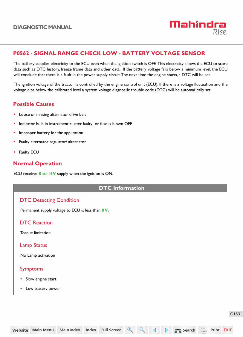
163G
DIAGNOSTIC MANUAL
P0562 - SIGNAL RANGE CHECK LOW - BATTERY VOLTAGE SENSOR
Possible Causes
The battery supplies electricity to the ECU even when the ignition switch is OFF. This electricity allows the ECU to store data such as DTC history, freeze frame data and other data. If the battery voltage falls below a minimum level, the ECU will conclude that there is a fault in the power supply circuit. The next time the engine starts, a DTC will be set.
The ignition voltage of the tractor is controlled by the engine control unit (ECU). If there is a voltage fluctuation and the voltage dips below the calibrated level a system voltage diagnostic trouble code (DTC) will be automatically set.
• Loose or missing alternator drive belt
• Indicator bulb in instrument cluster faulty or fuse is blown OFF
• Improper battery for the application
• Faulty alternator regulator/ alternator
• Faulty ECU
• Slow engine start
• Low battery power
Normal Operation
ECU receives 8 to 16V supply when the ignition is ON.
Permanent supply voltage to ECU is less than 8 V.
DTC Information
DTC Detecting Condition
DTC Reaction
Torque limitation
Lamp Status
No Lamp activation
Symptoms
91https://www.truck-manuals.net/

164G
DIAGNOSTIC MANUAL
Diagnostic ProcedureDiagnostic Procedure
1 Check whether the alternator drive belt is loose or damaged.
Go to Step 2
3 Check whether the charge indicator bulb or fuse is blown OFF.
Go to Step 4
4 Check the battery voltage. Go to Step 5
Acceptance Criteria
Voltage should be 8 to 16 V.
Step Test Procedure Yes No
• Replace the belt or adjust the belt tension.
• Replace the blown fuse. If problem repeats, replace the Instrument cluster.
2 Check whether the main charging fuse (battery charging 150 Amps) is blown OFF.
Go to Step 3• Replace the blown fuse.
• Recharge or replace the battery as required.
5 Run the engine at high idle speed and measure the voltage between Positive terminal and Negative or Ground terminal.
Acceptance Criteria
Voltage should be more than 12 V.
• Replace the alternator.• Clear the DTC and verify.
• If problem persists, replace the ECU with a new one.
• Clear the DTC and verify using the FES diagnostic tool.
• Activate the ignition for one driving cycle (ignition-OFF and ON).
Healing Condition
After performing the troubleshooting for each P Code, follow the below test procedure before driving the vehicle.
Upon completion of diagnostic procedure, clear the DTC. Ensure that the problem has been rectified and the DTC does not appear again.
92https://www.truck-manuals.net/
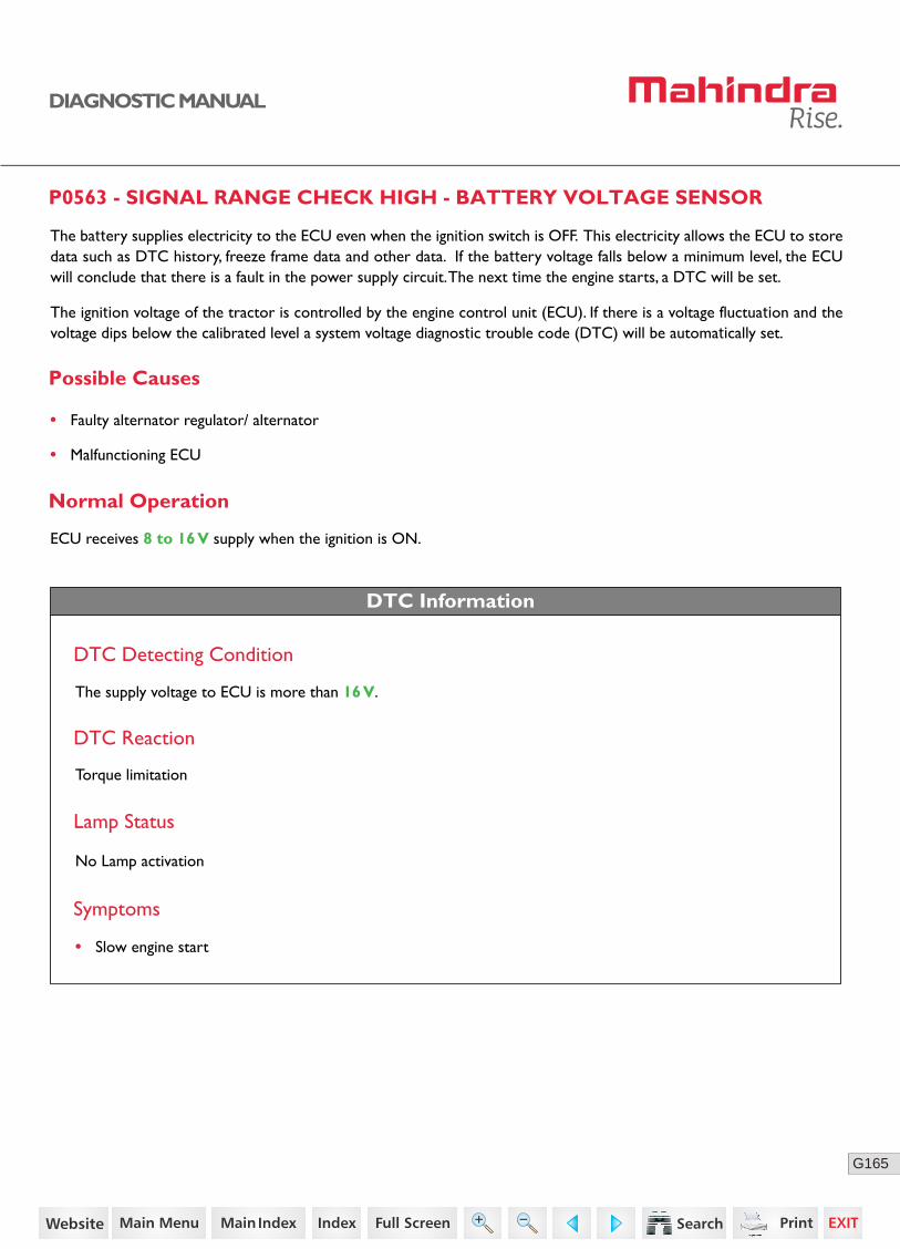
165G
DIAGNOSTIC MANUAL
P0563 - SIGNAL RANGE CHECK HIGH - BATTERY VOLTAGE SENSOR
Possible Causes
The battery supplies electricity to the ECU even when the ignition switch is OFF. This electricity allows the ECU to store data such as DTC history, freeze frame data and other data. If the battery voltage falls below a minimum level, the ECU will conclude that there is a fault in the power supply circuit. The next time the engine starts, a DTC will be set.
The ignition voltage of the tractor is controlled by the engine control unit (ECU). If there is a voltage fluctuation and the voltage dips below the calibrated level a system voltage diagnostic trouble code (DTC) will be automatically set.
• Faulty alternator regulator/ alternator
• Malfunctioning ECU
• Slow engine start
Normal Operation
ECU receives 8 to 16 V supply when the ignition is ON.
The supply voltage to ECU is more than 16 V.
DTC Information
DTC Detecting Condition
DTC Reaction
Lamp Status
Symptoms
No Lamp activation
Torque limitation
93https://www.truck-manuals.net/
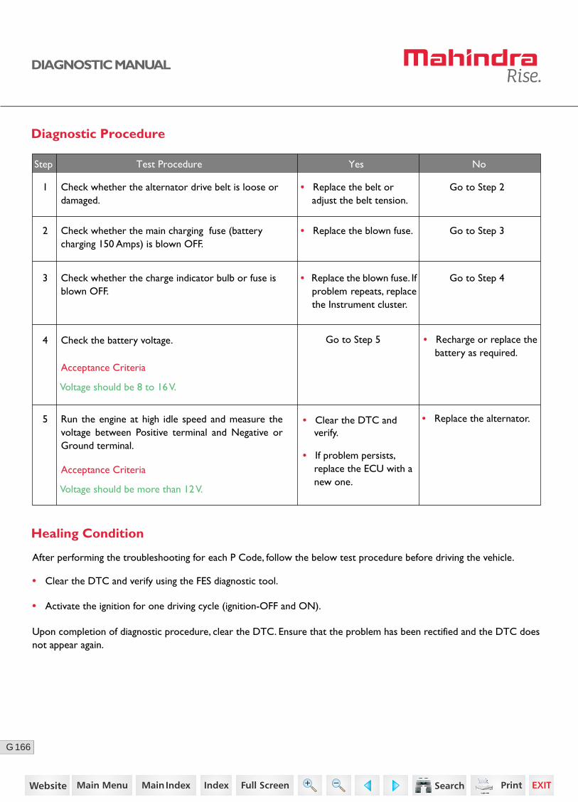
166G
DIAGNOSTIC MANUAL
Diagnostic Procedure
1 Check whether the alternator drive belt is loose or damaged.
Go to Step 2
3 Check whether the charge indicator bulb or fuse is blown OFF.
Go to Step 4
4 Check the battery voltage. Go to Step 5
Acceptance Criteria
Voltage should be 8 to 16 V.
Step Test Procedure Yes No
• Replace the belt or adjust the belt tension.
• Replace the blown fuse. If problem repeats, replace the Instrument cluster.
2 Check whether the main charging fuse (battery charging 150 Amps) is blown OFF.
Go to Step 3• Replace the blown fuse.
• Recharge or replace the battery as required.
5 Run the engine at high idle speed and measure the voltage between Positive terminal and Negative or Ground terminal.
Acceptance Criteria
Voltage should be more than 12 V.
• Replace the alternator.• Clear the DTC and verify.
• If problem persists, replace the ECU with a new one.
• Clear the DTC and verify using the FES diagnostic tool.
• Activate the ignition for one driving cycle (ignition-OFF and ON).
Healing Condition
After performing the troubleshooting for each P Code, follow the below test procedure before driving the vehicle.
Upon completion of diagnostic procedure, clear the DTC. Ensure that the problem has been rectified and the DTC does not appear again.
94https://www.truck-manuals.net/
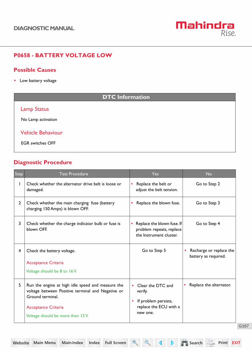
167G
DIAGNOSTIC MANUAL
P0658 - BATTERY VOLTAGE LOW
Possible Causes
• Low battery voltage
DTC Information
Lamp Status
No Lamp activation
Vehicle Behaviour
EGR switches OFF
Diagnostic Procedure
1 Check whether the alternator drive belt is loose or damaged.
Go to Step 2
3 Check whether the charge indicator bulb or fuse is blown OFF.
Go to Step 4
4 Check the battery voltage. Go to Step 5
Acceptance Criteria
Voltage should be 8 to 16 V.
Step Test Procedure Yes No
• Replace the belt or adjust the belt tension.
• Replace the blown fuse. If problem repeats, replace the Instrument cluster.
2 Check whether the main charging fuse (battery charging 150 Amps) is blown OFF.
Go to Step 3• Replace the blown fuse.
• Recharge or replace the battery as required.
5 Run the engine at high idle speed and measure the voltage between Positive terminal and Negative or Ground terminal.
Acceptance Criteria
Voltage should be more than 12 V.
• Replace the alternator.• Clear the DTC and verify.
• If problem persists, replace the ECU with a new one.
95https://www.truck-manuals.net/
168G
DIAGNOSTIC MANUAL
• Clear the DTC and verify using the FES diagnostic tool.
• Activate the ignition for one driving cycle (ignition-OFF and ON).
Healing Condition
After performing the troubleshooting for each P Code, follow the below test procedure before driving the vehicle.
Upon completion of diagnostic procedure, clear the DTC. Ensure that the problem has been rectified and the DTC does not appear again.
96https://www.truck-manuals.net/
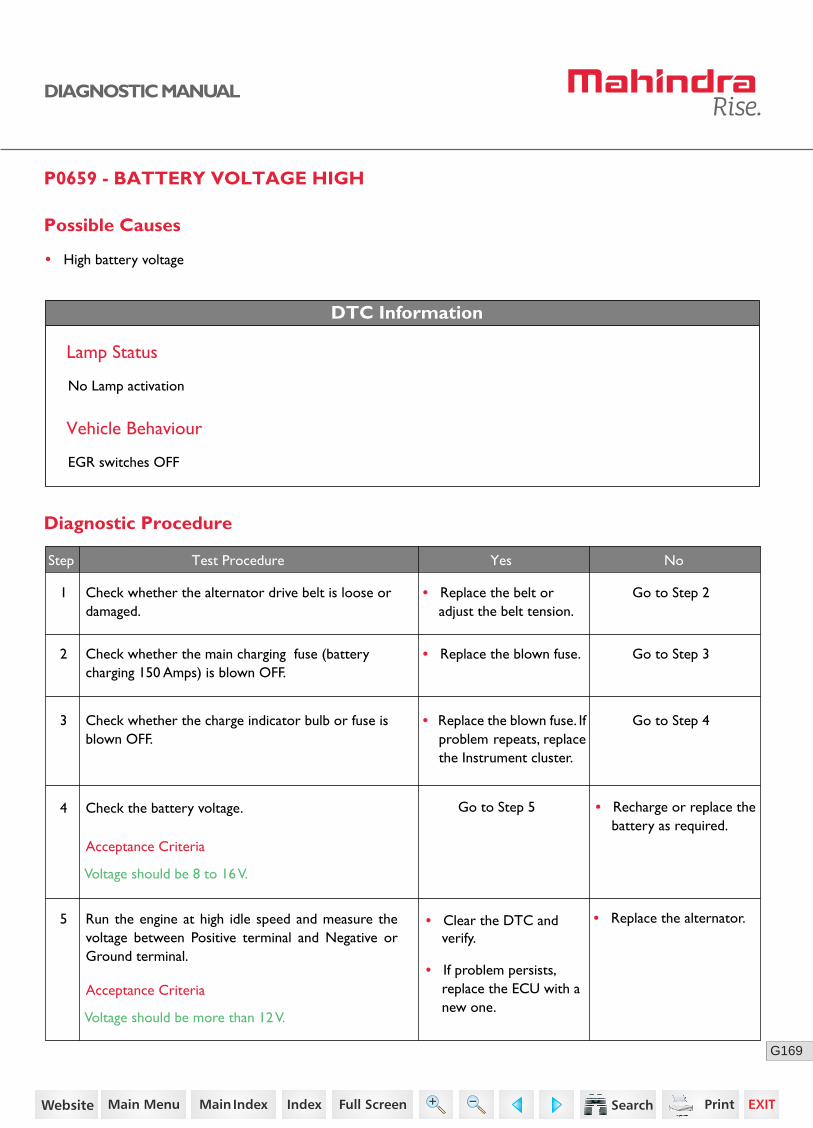
169G
DIAGNOSTIC MANUAL
P0659 - BATTERY VOLTAGE HIGH
Possible Causes
• High battery voltage
DTC Information
Lamp Status
No Lamp activation
Vehicle Behaviour
EGR switches OFF
Diagnostic Procedure
1 Check whether the alternator drive belt is loose or damaged.
Go to Step 2
3 Check whether the charge indicator bulb or fuse is blown OFF.
Go to Step 4
4 Check the battery voltage. Go to Step 5
Acceptance Criteria
Voltage should be 8 to 16 V.
Step Test Procedure Yes No
• Replace the belt or adjust the belt tension.
• Replace the blown fuse. If problem repeats, replace the Instrument cluster.
2 Check whether the main charging fuse (battery charging 150 Amps) is blown OFF.
Go to Step 3• Replace the blown fuse.
• Recharge or replace the battery as required.
5 Run the engine at high idle speed and measure the voltage between Positive terminal and Negative or Ground terminal.
Acceptance Criteria
Voltage should be more than 12 V.
• Replace the alternator.• Clear the DTC and verify.
• If problem persists, replace the ECU with a new one.
97https://www.truck-manuals.net/

170G
DIAGNOSTIC MANUAL
• Clear the DTC and verify using the FES diagnostic tool.
• Activate the ignition for one driving cycle (ignition-OFF and ON).
Healing Condition
After performing the troubleshooting for each P Code, follow the below test procedure before driving the vehicle.
Upon completion of diagnostic procedure, clear the DTC. Ensure that the problem has been rectified and the DTC does not appear again.
98https://www.truck-manuals.net/
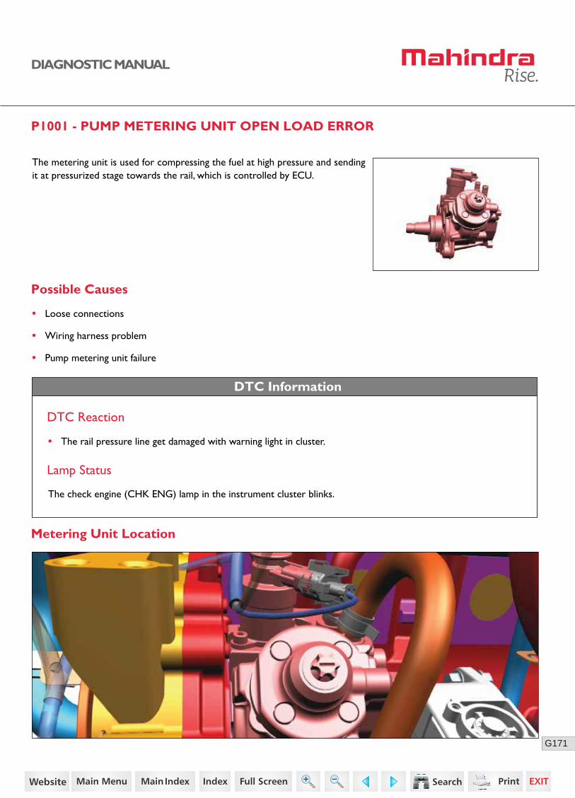
171G
DIAGNOSTIC MANUAL
P1001 - PUMP METERING UNIT OPEN LOAD ERROR
The metering unit is used for compressing the fuel at high pressure and sending it at pressurized stage towards the rail, which is controlled by ECU.
Possible Causes
• Loose connections
• Wiring harness problem
• Pump metering unit failure
DTC Information
DTC Reaction
• The rail pressure line get damaged with warning light in cluster.
Lamp Status
The check engine (CHK ENG) lamp in the instrument cluster blinks.
Metering Unit Location
99https://www.truck-manuals.net/

172G
DIAGNOSTIC MANUAL
Connector Pin Details
Diagnostic Procedure
1 Check whether the metering unit fuse is blown.
Check whether the metering unit connector pins are shorted with battery.
Go to Step 2
Go to Step 3
• Replace the blown fuse.
Step Test Procedure Yes No
2
3
Turn OFF the ignition switch.
Disconnect the ECU connector and pump metering unit connector.
Check continuity between the following:
• Replace the wiring harness.
• ECU connector pin K89 to metering unit connector pin 1.
• Metering unit fuse to metering unit connector pin 2.
Acceptance Criteria
Ensure proper continuity.
Acceptance Criteria
No short circuit to battery.
Fuel Metering Unit SensorECU
K89Fuel metering unit
Power supply
30
5 A
86 85
87
Main Relay
• Replace the wiring harness.
• Clear the DTC and verify.
• If the error repeats, replace the ECU with a new one.
100https://www.truck-manuals.net/
173G
DIAGNOSTIC MANUAL
• Clear the DTC and verify using the FES diagnostic tool.
• Activate the ignition for one driving cycle (ignition-OFF and ON).
Healing Condition
After performing the troubleshooting for each P Code, follow the below test procedure before driving the vehicle.
Upon completion of diagnostic procedure, clear the DTC. Ensure that the problem has been rectified and the DTC does not appear again.
101https://www.truck-manuals.net/

174G
DIAGNOSTIC MANUAL
P1106 - OVER CURRENT ERROR FOR EGR VALVE H-BRIDGE
Possible Causes
Electric Exhaust Gas Recirculation (EEGR) is a Nitrogen oxide (NOx) emissions reduction technique used in engines. The EEGR Position sensor detects the movement and position of the EEGR valve pintle. The EEGR Pressure sensor detects exhaust gas flow through the EEGR passage.
EEGR valve position sensors are mounted on the top of the EEGR valve. EEGR pressure sensors will be located close to the EEGR valve as the exhaust gas hose must be connected to the sensor as well as the valve. The EEGR monitor is designed to detect insufficientor excessive EEGR flow and component performance. When the EEGR valve is open, the ECU confirms that exhaust gas is flowing. When the EEGR valve is shut off, the ECU confirms exhaust gas flow has stopped. The sensors are also monitored for open, shorts, and performance.
• High current flow to ECU H-bridge and EGR valve failure/jammed
DTC Information
DTC Reaction
Lamp Status
Malfunction Indicator Lamp (MIL) in the instrument cluster glows continuously.
Sensor Location
Emission failure, EGR switches off and 30% torque deration
102https://www.truck-manuals.net/
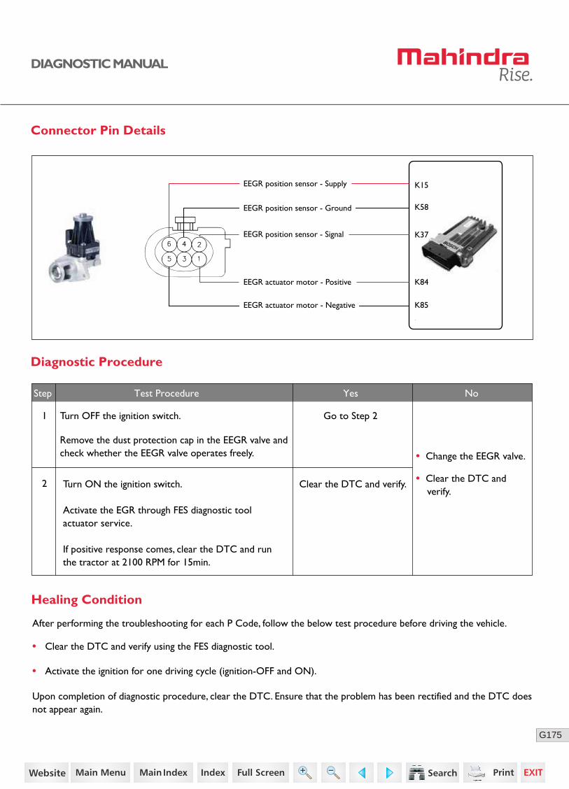
175G
DIAGNOSTIC MANUAL
Connector Pin Details
K85
K37
K58
K15EEGR position sensor - Supply
EEGR actuator motor - Positive
EEGR position sensor - Signal
EEGR position sensor - Ground
EEGR actuator motor - Negative
K84
No
Diagnostic Procedure
1
2
Turn OFF the ignition switch.
Remove the dust protection cap in the EEGR valve and check whether the EEGR valve operates freely.
Go to Step 2
Clear the DTC and verify.
• Change the EEGR valve.
• Clear the DTC and verify.
Step Test Procedure Yes No
• Clear the DTC and verify using the FES diagnostic tool.
• Activate the ignition for one driving cycle (ignition-OFF and ON).
Healing Condition
After performing the troubleshooting for each P Code, follow the below test procedure before driving the vehicle.
Upon completion of diagnostic procedure, clear the DTC. Ensure that the problem has been rectified and the DTC does not appear again.
Turn ON the ignition switch.
Activate the EGR through FES diagnostic tool actuator service.
If positive response comes, clear the DTC and run the tractor at 2100 RPM for 15min.
103https://www.truck-manuals.net/
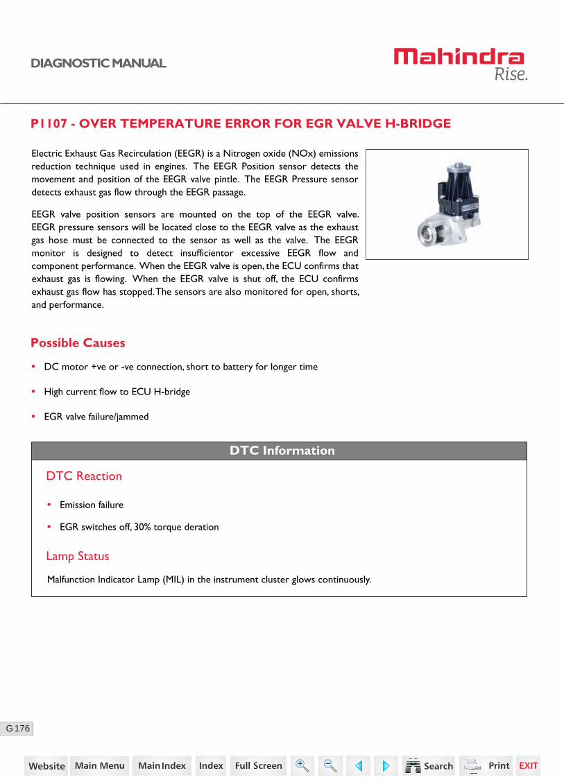
176G
DIAGNOSTIC MANUAL
P1107 - OVER TEMPERATURE ERROR FOR EGR VALVE H-BRIDGE
Possible Causes
Electric Exhaust Gas Recirculation (EEGR) is a Nitrogen oxide (NOx) emissions reduction technique used in engines. The EEGR Position sensor detects the movement and position of the EEGR valve pintle. The EEGR Pressure sensor detects exhaust gas flow through the EEGR passage.
EEGR valve position sensors are mounted on the top of the EEGR valve. EEGR pressure sensors will be located close to the EEGR valve as the exhaust gas hose must be connected to the sensor as well as the valve. The EEGR monitor is designed to detect insufficientor excessive EEGR flow and component performance. When the EEGR valve is open, the ECU confirms that exhaust gas is flowing. When the EEGR valve is shut off, the ECU confirms exhaust gas flow has stopped. The sensors are also monitored for open, shorts, and performance.
• DC motor +ve or -ve connection, short to battery for longer time
• High current flow to ECU H-bridge
• EGR valve failure/jammed
DTC Information
DTC Reaction
Lamp Status
Malfunction Indicator Lamp (MIL) in the instrument cluster glows continuously.
• Emission failure
• EGR switches off, 30% torque deration
104https://www.truck-manuals.net/

177G
DIAGNOSTIC MANUAL
Sensor Location
Connector Pin Details
EGR Valve ECUK85
K37
K58
K15EEGR position sensor - Supply
EEGR actuator motor - Positive
EEGR position sensor - Signal
EEGR position sensor - Ground
EEGR actuator motor - Negative
K84
105https://www.truck-manuals.net/
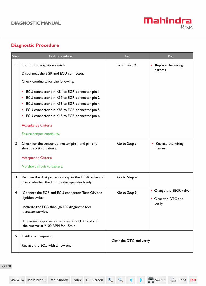
178G
DIAGNOSTIC MANUAL
2 Check for the sensor connector pin 1 and pin 5 forshort circuit to battery.
Go to Step 3 • Replace the wiring harness.
If still error repeats,
Replace the ECU with a new one.
Acceptance Criteria
Step Test Procedure Yes No
5Clear the DTC and verify.
No short circuit to battery.
Diagnostic Procedure
1 Turn OFF the ignition switch.
Disconnect the EGR and ECU connector.
Check continuity for the following:
• ECU connector pin K84 to EGR connector pin 1
• ECU connector pin K37 to EGR connector pin 2
• ECU connector pin K58 to EGR connector pin 4
• ECU connector pin K85 to EGR connector pin 5
• ECU connector pin K15 to EGR connector pin 6
Go to Step 2 • Replace the wiring harness.
Acceptance Criteria
Ensure proper continuity.
3
4
Remove the dust protection cap in the EEGR valve and check whether the EEGR valve operates freely.
Go to Step 4
Go to Step 5 • Change the EEGR valve.
• Clear the DTC and verify.
Connect the EGR and ECU connector. Turn ON the ignition switch.
Activate the EGR through FES diagnostic tool actuator service.
If positive response comes, clear the DTC and run the tractor at 2100 RPM for 15min.
106https://www.truck-manuals.net/
179G
DIAGNOSTIC MANUAL
• Clear the DTC and verify using the FES diagnostic tool.
• Activate the ignition for one driving cycle (ignition-OFF and ON).
Healing Condition
After performing the troubleshooting for each P Code, follow the below test procedure before driving the vehicle.
Upon completion of diagnostic procedure, clear the DTC. Ensure that the problem has been rectified and the DTC does not appear again.
107https://www.truck-manuals.net/

180G
DIAGNOSTIC MANUAL
P1108 - SHORT CIRCUIT TO BATTERY ON OUT1 ERROR FOR EGR VALVE H-BRIDGE
Possible Causes
Electric Exhaust Gas Recirculation (EEGR) is a Nitrogen oxide (NOx) emissions reduction technique used in engines. The EEGR Position sensor detects the movement and position of the EEGR valve pintle. The EEGR Pressure sensor detects exhaust gas flow through the EEGR passage.
EEGR valve position sensors are mounted on the top of the EEGR valve. EEGR pressure sensors will be located close to the EEGR valve as the exhaust gas hose must be connected to the sensor as well as the valve. The EEGR monitor is designed to detect insufficientor excessive EEGR flow and component performance. When the EEGR valve is open, the ECU confirms that exhaust gas is flowing. When the EEGR valve is shut off, the ECU confirms exhaust gas flow has stopped. The sensors are also monitored for open, shorts, and performance.
• DC motor +ve short circuit to battery
DTC Information
DTC Reaction
• Emission failure
Lamp Status
Malfunction Indicator Lamp (MIL) in the instrument cluster glows continuously.
• EGR switches off, 30% torque deration
108https://www.truck-manuals.net/

181G
DIAGNOSTIC MANUAL
Sensor Location
Connector Pin Details
EGR Valve ECUK85
K37
K58
K15EEGR position sensor - Supply
EEGR actuator motor - Positive
EEGR position sensor - Signal
EEGR position sensor - Ground
EEGR actuator motor - Negative
K84
109https://www.truck-manuals.net/

182G
DIAGNOSTIC MANUAL
Diagnostic Procedure
2 Turn OFF the ignition switch.
Disconnect the EGR and ECU connector.
Check continuity for the following:
• ECU connector pin K84 to EGR connector pin 1
• ECU connector pin K37 to EGR connector pin 2
• ECU connector pin K58 to EGR connector pin 4
• ECU connector pin K85 to EGR connector pin 5
• ECU connector pin K15 to EGR connector pin 6
Go to Step 3
Go to Step 4
Go to Step 5
• Replace the wiring harness.
4 Turn ON the ignition with ECU connector connected.
Check the supply voltage between EGR Connector pin 1 and 5.
3 Check the sensor supply line (pin no. 6), EGR motor +ve (pin no. 1), EGR motor -ve (pin no.5) and EGR position sensor (pin no. 2) is short circuited to ground/battery positive.
Acceptance Criteria
Acceptance Criteria
Voltage = 5 ± 0.2V
Acceptance Criteria
No short circuit to ground/battery positive.
Step Test Procedure Yes No
• Replace the wiring harness.
Ensure proper continuity.
1 Go to Step 2 • Ensure proper fitment.Check for the proper fitment of EGR valve and connec-tor.
• Replace the ECU.
110https://www.truck-manuals.net/

183G
DIAGNOSTIC MANUAL
• Clear the DTC and verify using the FES diagnostic tool.
• Activate the ignition for one driving cycle (ignition-OFF and ON).
After performing the troubleshooting for each P Code, follow the below test procedure before driving the vehicle.
Upon completion of diagnostic procedure, clear the DTC. Ensure that the problem has been rectified and the DTC does not appear again.
Healing Condition
Step Test Procedure Further Action
5Clear the DTC and verify.
If still error repeats,
Replace the EGR with a new one.
111https://www.truck-manuals.net/
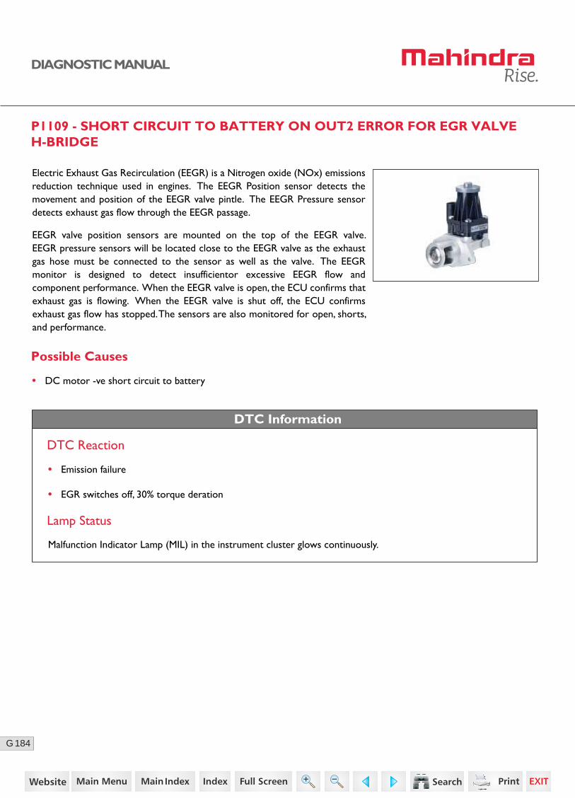
184G
DIAGNOSTIC MANUAL
P1109 - SHORT CIRCUIT TO BATTERY ON OUT2 ERROR FOR EGR VALVE H-BRIDGE
Possible Causes
Electric Exhaust Gas Recirculation (EEGR) is a Nitrogen oxide (NOx) emissions reduction technique used in engines. The EEGR Position sensor detects the movement and position of the EEGR valve pintle. The EEGR Pressure sensor detects exhaust gas flow through the EEGR passage.
EEGR valve position sensors are mounted on the top of the EEGR valve. EEGR pressure sensors will be located close to the EEGR valve as the exhaust gas hose must be connected to the sensor as well as the valve. The EEGR monitor is designed to detect insufficientor excessive EEGR flow and component performance. When the EEGR valve is open, the ECU confirms that exhaust gas is flowing. When the EEGR valve is shut off, the ECU confirms exhaust gas flow has stopped. The sensors are also monitored for open, shorts, and performance.
• DC motor -ve short circuit to battery
DTC Information
DTC Reaction
• Emission failure
Lamp Status
Malfunction Indicator Lamp (MIL) in the instrument cluster glows continuously.
• EGR switches off, 30% torque deration
112https://www.truck-manuals.net/
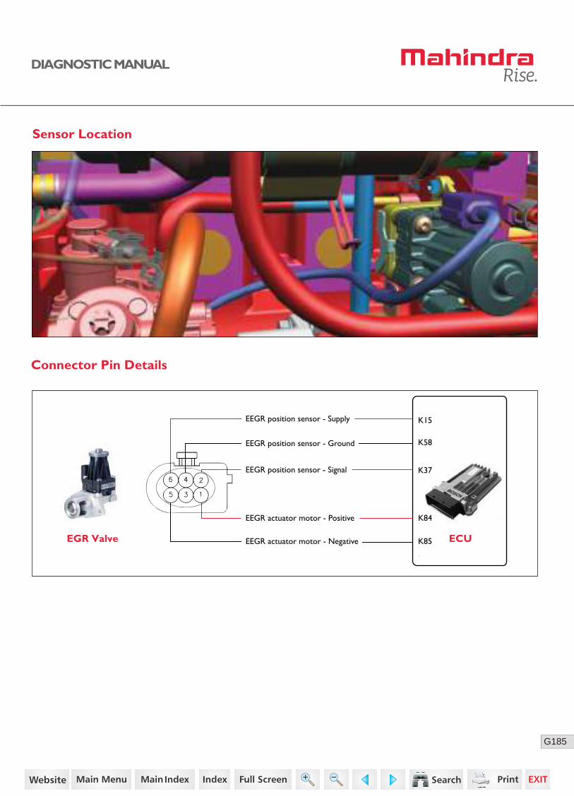
185G
DIAGNOSTIC MANUAL
Sensor Location
Connector Pin Details
EGR Valve ECUK85
K37
K58
K15EEGR position sensor - Supply
EEGR actuator motor - Positive
EEGR position sensor - Signal
EEGR position sensor - Ground
EEGR actuator motor - Negative
K84
113https://www.truck-manuals.net/

186G
DIAGNOSTIC MANUAL
Diagnostic Procedure
2 Turn OFF the ignition switch.
Disconnect the EGR and ECU connector.
Check continuity for the following:
• ECU connector pin K84 to EGR connector pin 1
• ECU connector pin K37 to EGR connector pin 2
• ECU connector pin K58 to EGR connector pin 4
• ECU connector pin K85 to EGR connector pin 5
• ECU connector pin K15 to EGR connector pin 6
Go to Step 3
Go to Step 4
Go to Step 5
• Replace the wiring harness.
4 Turn ON the ignition with ECU connector connected.
Check the supply voltage between EGR Connector pin 1 and 5.
3 Check the sensor supply line (pin no. 6), EGR motor +ve (pin no. 1), EGR motor -ve (pin no.5) and EGR position sensor (pin no. 2) is short circuited to ground/battery positive.
Acceptance Criteria
Acceptance Criteria
Voltage = 5 ± 0.2V
Acceptance Criteria
No short circuit to ground/battery positive.
Step Test Procedure Yes No
• Replace the wiring harness.
Ensure proper continuity.
1 Go to Step 2 • Ensure proper fitment.Check for the proper fitment of EGR valve and connec-tor.
• Replace the ECU.
114https://www.truck-manuals.net/

187G
DIAGNOSTIC MANUAL
• Clear the DTC and verify using the FES diagnostic tool.
• Activate the ignition for one driving cycle (ignition-OFF and ON).
After performing the troubleshooting for each P Code, follow the below test procedure before driving the vehicle.
Upon completion of diagnostic procedure, clear the DTC. Ensure that the problem has been rectified and the DTC does not appear again.
Healing Condition
Step Test Procedure Further Action
5Clear the DTC and verify.
If still error repeats,
Replace the EGR with a new one.
115https://www.truck-manuals.net/
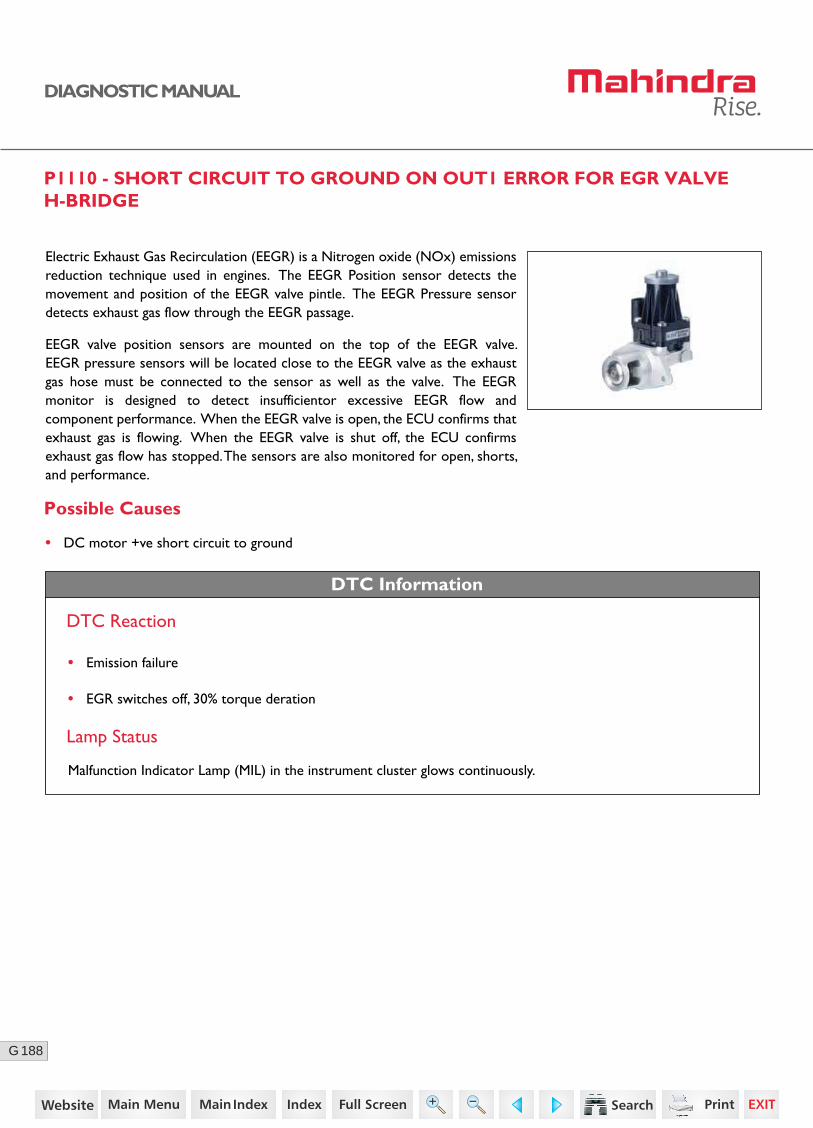
188G
DIAGNOSTIC MANUAL
P1110 - SHORT CIRCUIT TO GROUND ON OUT1 ERROR FOR EGR VALVE H-BRIDGE
Possible Causes
Electric Exhaust Gas Recirculation (EEGR) is a Nitrogen oxide (NOx) emissions reduction technique used in engines. The EEGR Position sensor detects the movement and position of the EEGR valve pintle. The EEGR Pressure sensor detects exhaust gas flow through the EEGR passage.
EEGR valve position sensors are mounted on the top of the EEGR valve. EEGR pressure sensors will be located close to the EEGR valve as the exhaust gas hose must be connected to the sensor as well as the valve. The EEGR monitor is designed to detect insufficientor excessive EEGR flow and component performance. When the EEGR valve is open, the ECU confirms that exhaust gas is flowing. When the EEGR valve is shut off, the ECU confirms exhaust gas flow has stopped. The sensors are also monitored for open, shorts, and performance.
• DC motor +ve short circuit to ground
DTC Information
DTC Reaction
Lamp Status
Malfunction Indicator Lamp (MIL) in the instrument cluster glows continuously.
• Emission failure
• EGR switches off, 30% torque deration
116https://www.truck-manuals.net/

189G
DIAGNOSTIC MANUAL
Sensor Location
Connector Pin Details
EGR Valve ECUK85
K37
K58
K15EEGR position sensor - Supply
EEGR actuator motor - Positive
EEGR position sensor - Signal
EEGR position sensor - Ground
EEGR actuator motor - Negative
K84
117https://www.truck-manuals.net/

190G
DIAGNOSTIC MANUAL
Diagnostic Procedure
2 Turn OFF the ignition switch.
Disconnect the EGR and ECU connector.
Check continuity for the following:
• ECU connector pin K84 to EGR connector pin 1
• ECU connector pin K37 to EGR connector pin 2
• ECU connector pin K58 to EGR connector pin 4
• ECU connector pin K85 to EGR connector pin 5
• ECU connector pin K15 to EGR connector pin 6
Go to Step 3
Go to Step 4
Go to Step 5
• Replace the wiring harness.
4 Turn ON the ignition with ECU connector connected.
Check the supply voltage between EGR Connector pin 1 and 5.
3 Check the sensor supply line (pin no. 6), EGR motor +ve (pin no. 1), EGR motor -ve (pin no.5) and EGR position sensor (pin no. 2) is short circuited to ground/battery positive.
Acceptance Criteria
Acceptance Criteria
Voltage = 5 ± 0.2V
Acceptance Criteria
No short circuit to ground/battery positive.
Step Test Procedure Yes No
• Replace the wiring harness.
Ensure proper continuity.
1 Go to Step 2 • Ensure proper fitment.Check for the proper fitment of EGR valve and connec-tor.
• Replace the ECU.
118https://www.truck-manuals.net/

191G
DIAGNOSTIC MANUAL
• Clear the DTC and verify using the FES diagnostic tool.
• Activate the ignition for one driving cycle (ignition-OFF and ON).
After performing the troubleshooting for each P Code, follow the below test procedure before driving the vehicle.
Upon completion of diagnostic procedure, clear the DTC. Ensure that the problem has been rectified and the DTC does not appear again.
Healing Condition
Step Test Procedure Further Action
5Clear the DTC and verify.
If still error repeats,
Replace the EGR with a new one.
119https://www.truck-manuals.net/
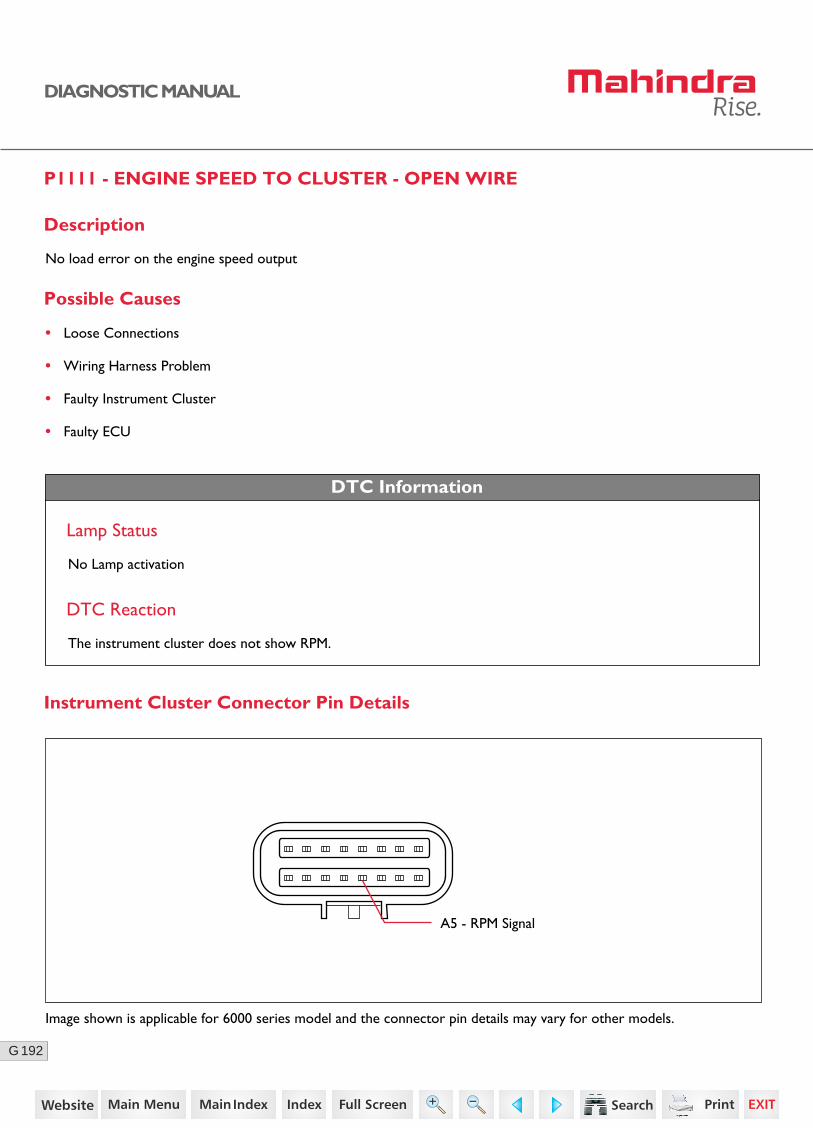
192G
DIAGNOSTIC MANUAL
P1111 - ENGINE SPEED TO CLUSTER - OPEN WIRE
Description
No load error on the engine speed output
Possible Causes
• Loose Connections
• Wiring Harness Problem
• Faulty Instrument Cluster
• Faulty ECU
DTC Information
DTC Reaction
The instrument cluster does not show RPM.
A5 - RPM Signal
Lamp Status
No Lamp activation
Instrument Cluster Connector Pin Details
Image shown is applicable for 6000 series model and the connector pin details may vary for other models.
120https://www.truck-manuals.net/
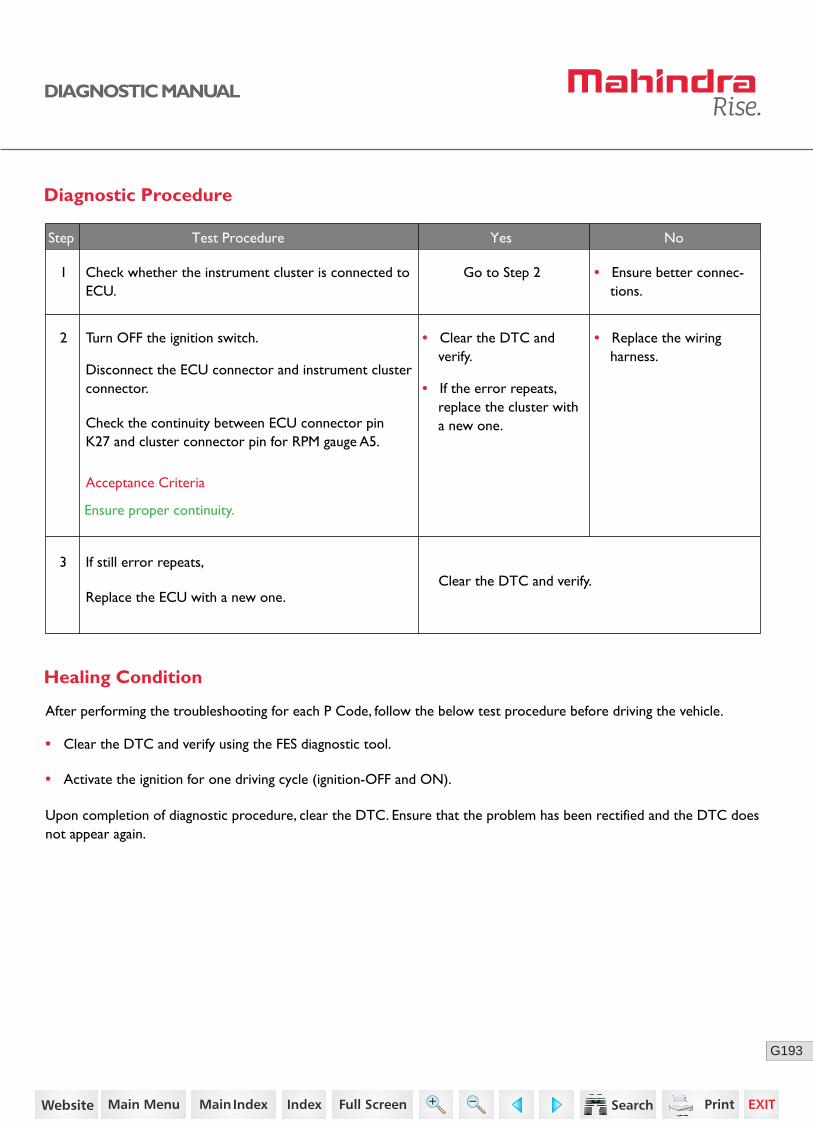
193G
DIAGNOSTIC MANUAL
3
• Clear the DTC and verify.
• If the error repeats, replace the cluster with a new one.
No
• Clear the DTC and verify using the FES diagnostic tool.
• Activate the ignition for one driving cycle (ignition-OFF and ON).
Healing Condition
After performing the troubleshooting for each P Code, follow the below test procedure before driving the vehicle.
Upon completion of diagnostic procedure, clear the DTC. Ensure that the problem has been rectified and the DTC does not appear again.
Diagnostic Procedure
2 Turn OFF the ignition switch.
Disconnect the ECU connector and instrument cluster connector.
Check the continuity between ECU connector pin K27 and cluster connector pin for RPM gauge A5.
• Replace the wiring harness.
1 Check whether the instrument cluster is connected to ECU.
Go to Step 2 • Ensure better connec-tions.
Acceptance Criteria
Ensure proper continuity.
Step Test Procedure Yes No
If still error repeats,
Replace the ECU with a new one.Clear the DTC and verify.
121https://www.truck-manuals.net/
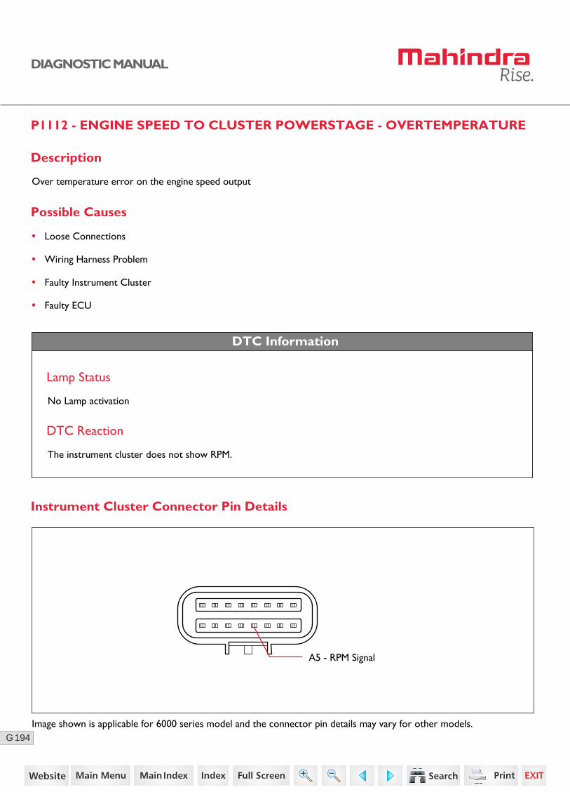
194G
DIAGNOSTIC MANUAL
DTC Information
Lamp Status
No Lamp activation
DTC Reaction
The instrument cluster does not show RPM.
Possible Causes
• Loose Connections
• Wiring Harness Problem
• Faulty Instrument Cluster
• Faulty ECU
A5 - RPM Signal
Instrument Cluster Connector Pin Details
P1112 - ENGINE SPEED TO CLUSTER POWERSTAGE - OVERTEMPERATURE
Description
Over temperature error on the engine speed output
Image shown is applicable for 6000 series model and the connector pin details may vary for other models.
122https://www.truck-manuals.net/
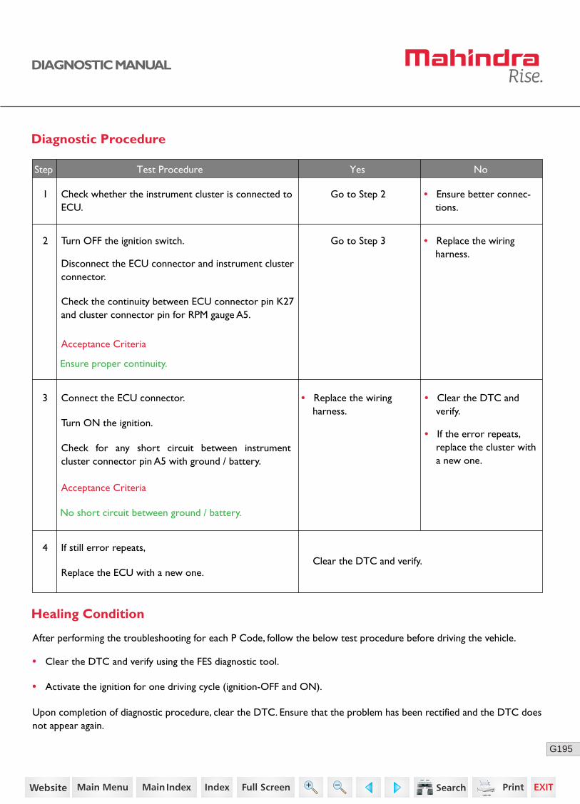
195G
DIAGNOSTIC MANUAL
3 Connect the ECU connector.
Turn ON the ignition.
Check for any short circuit between instrument cluster connector pin A5 with ground / battery.
• Replace the wiring harness.
No
Diagnostic Procedure
2 Turn OFF the ignition switch.
Disconnect the ECU connector and instrument cluster connector.
Check the continuity between ECU connector pin K27 and cluster connector pin for RPM gauge A5.
• Replace the wiring harness.
1 Check whether the instrument cluster is connected to ECU.
Go to Step 2 • Ensure better connec-tions.
Acceptance Criteria
Ensure proper continuity.
Step Test Procedure Yes No
Go to Step 3
Acceptance Criteria
No short circuit between ground / battery.
4
• Clear the DTC and verify.
• If the error repeats, replace the cluster with a new one.
If still error repeats,
Replace the ECU with a new one.Clear the DTC and verify.
• Clear the DTC and verify using the FES diagnostic tool.
• Activate the ignition for one driving cycle (ignition-OFF and ON).
Healing Condition
After performing the troubleshooting for each P Code, follow the below test procedure before driving the vehicle.
Upon completion of diagnostic procedure, clear the DTC. Ensure that the problem has been rectified and the DTC does not appear again.
123https://www.truck-manuals.net/
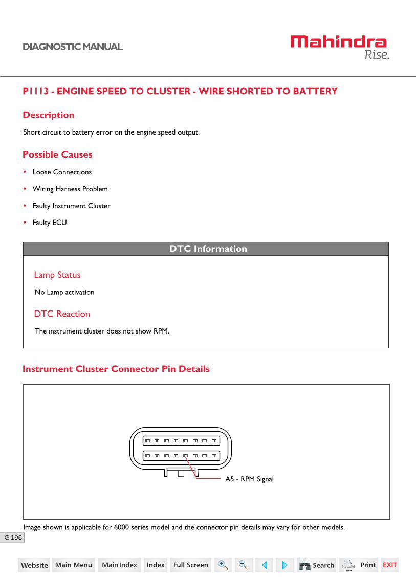
196G
DIAGNOSTIC MANUAL
DTC Information
Lamp Status
No Lamp activation
DTC Reaction
The instrument cluster does not show RPM.
Possible Causes
• Loose Connections
• Wiring Harness Problem
• Faulty Instrument Cluster
• Faulty ECU
A5 - RPM Signal
Instrument Cluster Connector Pin Details
P1113 - ENGINE SPEED TO CLUSTER - WIRE SHORTED TO BATTERY
Description
Short circuit to battery error on the engine speed output.
Image shown is applicable for 6000 series model and the connector pin details may vary for other models.
124https://www.truck-manuals.net/

197G
DIAGNOSTIC MANUAL
3 Connect the ECU connector.
Turn ON the ignition.
Check for any short circuit between instrument cluster connector pin A5 with ground / battery.
• Replace the wiring harness.
No
Diagnostic Procedure
2 Turn OFF the ignition switch.
Disconnect the ECU connector and instrument cluster connector.
Check the continuity between ECU onnector pin K27 and cluster connector pin for RPM gauge A5.
• Replace the wiring harness.
1 Check whether the instrument cluster is connected to ECU.
Go to Step 2 • Ensure better connec-tions.
Acceptance Criteria
Ensure proper continuity.
Step Test Procedure Yes No
Go to Step 3
Acceptance Criteria
No short circuit between ground / battery.
4
• Clear the DTC and verify.
• If the error repeats, replace the cluster with a new one.
If still error repeats,
Replace the ECU with a new one.Clear the DTC and verify.
• Clear the DTC and verify using the FES diagnostic tool.
• Activate the ignition for one driving cycle (ignition-OFF and ON).
Healing Condition
After performing the troubleshooting for each P Code, follow the below test procedure before driving the vehicle.
Upon completion of diagnostic procedure, clear the DTC. Ensure that the problem has been rectified and the DTC does not appear again.
125https://www.truck-manuals.net/
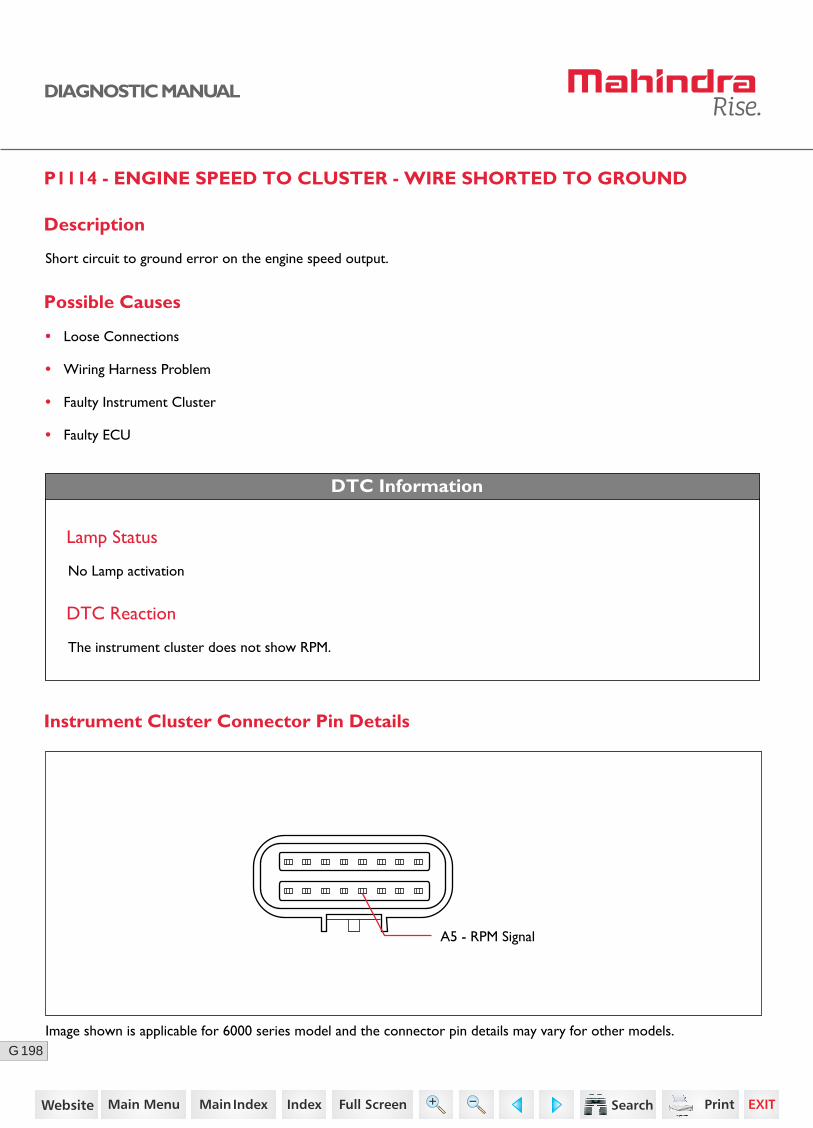
198G
DIAGNOSTIC MANUAL
P1114 - ENGINE SPEED TO CLUSTER - WIRE SHORTED TO GROUND
Description
Short circuit to ground error on the engine speed output.
DTC Information
Lamp Status
No Lamp activation
DTC Reaction
The instrument cluster does not show RPM.
Possible Causes
• Loose Connections
• Wiring Harness Problem
• Faulty Instrument Cluster
• Faulty ECU
A5 - RPM Signal
Instrument Cluster Connector Pin Details
Image shown is applicable for 6000 series model and the connector pin details may vary for other models.
126https://www.truck-manuals.net/

199G
DIAGNOSTIC MANUAL
3 Connect the ECU connector.
Turn ON the ignition.
Check for any short circuit between instrument cluster connector pin A5 with ground / battery.
• Replace the wiring harness.
No
Diagnostic Procedure
2 Turn OFF the ignition switch.
Disconnect the ECU connector and instrument cluster connector.
Check the continuity between ECU connector pin K27 and cluster connector pin for RPM gauge A5.
• Replace the wiring harness.
1 Check whether the instrument cluster is connected to ECU.
Go to Step 2 • Ensure better connec-tions.
Acceptance Criteria
Ensure proper continuity.
Step Test Procedure Yes No
Go to Step 3
Acceptance Criteria
No short circuit between ground / battery.
4
• Clear the DTC and verify.
• If the error repeats, replace the cluster with a new one.
If still error repeats,
Replace the ECU with a new one.Clear the DTC and verify.
• Clear the DTC and verify using the FES diagnostic tool.
• Activate the ignition for one driving cycle (ignition-OFF and ON).
Healing Condition
After performing the troubleshooting for each P Code, follow the below test procedure before driving the vehicle.
Upon completion of diagnostic procedure, clear the DTC. Ensure that the problem has been rectified and the DTC does not appear again.
127https://www.truck-manuals.net/
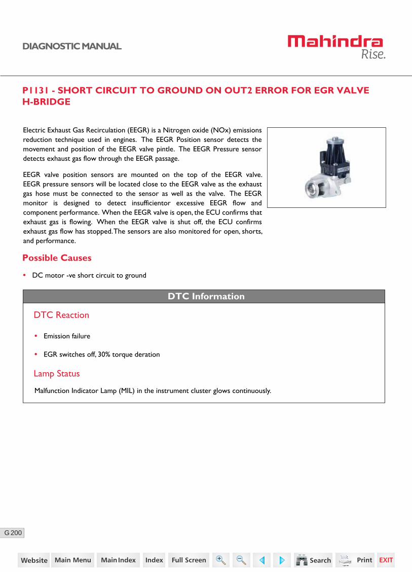
200G
DIAGNOSTIC MANUAL
P1131 - SHORT CIRCUIT TO GROUND ON OUT2 ERROR FOR EGR VALVE H-BRIDGE
Possible Causes
Electric Exhaust Gas Recirculation (EEGR) is a Nitrogen oxide (NOx) emissions reduction technique used in engines. The EEGR Position sensor detects the movement and position of the EEGR valve pintle. The EEGR Pressure sensor detects exhaust gas flow through the EEGR passage.
EEGR valve position sensors are mounted on the top of the EEGR valve. EEGR pressure sensors will be located close to the EEGR valve as the exhaust gas hose must be connected to the sensor as well as the valve. The EEGR monitor is designed to detect insufficientor excessive EEGR flow and component performance. When the EEGR valve is open, the ECU confirms that exhaust gas is flowing. When the EEGR valve is shut off, the ECU confirms exhaust gas flow has stopped. The sensors are also monitored for open, shorts, and performance.
• DC motor -ve short circuit to ground
DTC Information
DTC Reaction
Lamp Status
Malfunction Indicator Lamp (MIL) in the instrument cluster glows continuously.
• Emission failure
• EGR switches off, 30% torque deration
128https://www.truck-manuals.net/

201G
DIAGNOSTIC MANUAL
Sensor Location
Connector Pin Details
EGR Valve ECUK85
K37
K58
K15EEGR position sensor - Supply
EEGR actuator motor - Positive
EEGR position sensor - Signal
EEGR position sensor - Ground
EEGR actuator motor - Negative
K84
129https://www.truck-manuals.net/
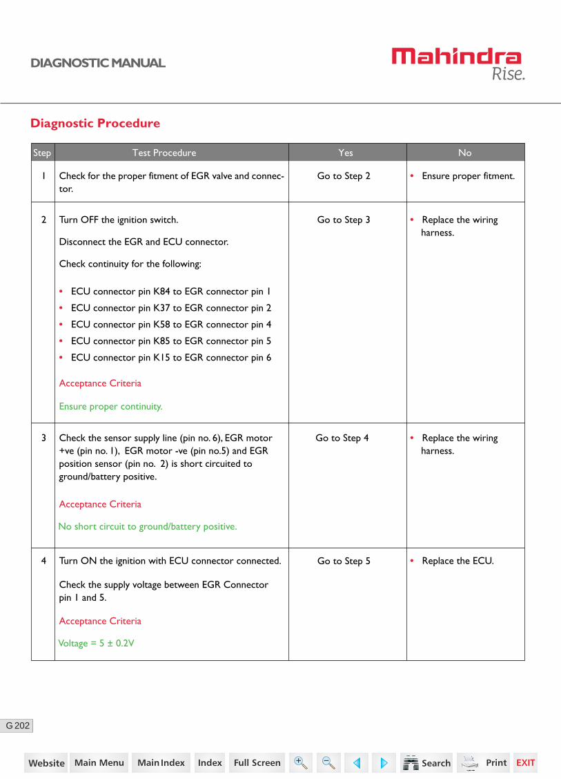
202G
DIAGNOSTIC MANUAL
Diagnostic Procedure
2 Turn OFF the ignition switch.
Disconnect the EGR and ECU connector.
Check continuity for the following:
• ECU connector pin K84 to EGR connector pin 1
• ECU connector pin K37 to EGR connector pin 2
• ECU connector pin K58 to EGR connector pin 4
• ECU connector pin K85 to EGR connector pin 5
• ECU connector pin K15 to EGR connector pin 6
Go to Step 3
Go to Step 4
Go to Step 5
• Replace the wiring harness.
4 Turn ON the ignition with ECU connector connected.
Check the supply voltage between EGR Connector pin 1 and 5.
3 Check the sensor supply line (pin no. 6), EGR motor +ve (pin no. 1), EGR motor -ve (pin no.5) and EGR position sensor (pin no. 2) is short circuited to ground/battery positive.
Acceptance Criteria
Acceptance Criteria
Voltage = 5 ± 0.2V
Acceptance Criteria
No short circuit to ground/battery positive.
Step Test Procedure Yes No
• Replace the wiring harness.
Ensure proper continuity.
1 Go to Step 2 • Ensure proper fitment.Check for the proper fitment of EGR valve and connec-tor.
• Replace the ECU.
130https://www.truck-manuals.net/

203G
DIAGNOSTIC MANUAL
• Clear the DTC and verify using the FES diagnostic tool.
• Activate the ignition for one driving cycle (ignition-OFF and ON).
After performing the troubleshooting for each P Code, follow the below test procedure before driving the vehicle.
Upon completion of diagnostic procedure, clear the DTC. Ensure that the problem has been rectified and the DTC does not appear again.
Healing Condition
Step Test Procedure Further Action
5Clear the DTC and verify.
If still error repeats,
Replace the EGR with a new one.
131https://www.truck-manuals.net/
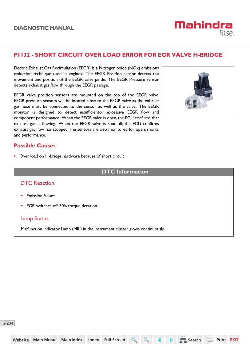
204G
DIAGNOSTIC MANUAL
P1132 - SHORT CIRCUIT OVER LOAD ERROR FOR EGR VALVE H-BRIDGE
Possible Causes
Electric Exhaust Gas Recirculation (EEGR) is a Nitrogen oxide (NOx) emissions reduction technique used in engines. The EEGR Position sensor detects the movement and position of the EEGR valve pintle. The EEGR Pressure sensor detects exhaust gas flow through the EEGR passage.
EEGR valve position sensors are mounted on the top of the EEGR valve. EEGR pressure sensors will be located close to the EEGR valve as the exhaust gas hose must be connected to the sensor as well as the valve. The EEGR monitor is designed to detect insufficientor excessive EEGR flow and component performance. When the EEGR valve is open, the ECU confirms that exhaust gas is flowing. When the EEGR valve is shut off, the ECU confirms exhaust gas flow has stopped. The sensors are also monitored for open, shorts, and performance.
• Over load on H-bridge hardware because of short circuit
DTC Information
DTC Reaction
Lamp Status
Malfunction Indicator Lamp (MIL) in the instrument cluster glows continuously.
• Emission failure
• EGR switches off, 30% torque deration
132https://www.truck-manuals.net/

205G
DIAGNOSTIC MANUAL
Sensor Location
Connector Pin Details
EGR Valve ECUK85
K37
K58
K15EEGR position sensor - Supply
EEGR actuator motor - Positive
EEGR position sensor - Signal
EEGR position sensor - Ground
EEGR actuator motor - Negative
K84
133https://www.truck-manuals.net/

206G
DIAGNOSTIC MANUAL
Diagnostic Procedure
2 Turn OFF the ignition switch.
Disconnect the EGR and ECU connector.
Check continuity for the following:
• ECU connector pin K84 to EGR connector pin 1
• ECU connector pin K37 to EGR connector pin 2
• ECU connector pin K58 to EGR connector pin 4
• ECU connector pin K85 to EGR connector pin 5
• ECU connector pin K15 to EGR connector pin 6
Go to Step 3
Go to Step 4
Go to Step 5
• Replace the wiring harness.
4 Turn ON the ignition with ECU connector connected.
Check the supply voltage between EGR Connector pin 1 and 5.
3 Check the sensor supply line (pin no. 6), EGR motor +ve (pin no. 1), EGR motor -ve (pin no.5) and EGR position sensor (pin no. 2) is short circuited to ground/battery positive.
Acceptance Criteria
Acceptance Criteria
Voltage = 5 ± 0.2V
Acceptance Criteria
No short circuit to ground/battery positive.
Step Test Procedure Yes No
• Replace the wiring harness.
Ensure proper continuity.
1 Go to Step 2 • Ensure proper fitment.Check for the proper fitment of EGR valve and connec-tor.
• Replace the ECU.
134https://www.truck-manuals.net/

207G
DIAGNOSTIC MANUAL
• Clear the DTC and verify using the FES diagnostic tool.
• Activate the ignition for one driving cycle (ignition-OFF and ON).
After performing the troubleshooting for each P Code, follow the below test procedure before driving the vehicle.
Upon completion of diagnostic procedure, clear the DTC. Ensure that the problem has been rectified and the DTC does not appear again.
Healing Condition
Step Test Procedure Further Action
5Clear the DTC and verify.
If still error repeats,
Replace the EGR with a new one.
135https://www.truck-manuals.net/
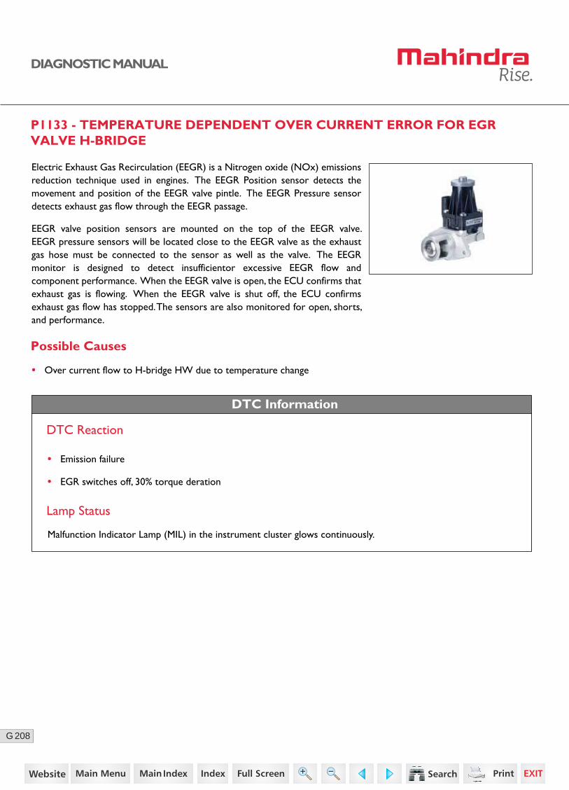
208G
DIAGNOSTIC MANUAL
P1133 - TEMPERATURE DEPENDENT OVER CURRENT ERROR FOR EGR VALVE H-BRIDGE
Possible Causes
Electric Exhaust Gas Recirculation (EEGR) is a Nitrogen oxide (NOx) emissions reduction technique used in engines. The EEGR Position sensor detects the movement and position of the EEGR valve pintle. The EEGR Pressure sensor detects exhaust gas flow through the EEGR passage.
EEGR valve position sensors are mounted on the top of the EEGR valve. EEGR pressure sensors will be located close to the EEGR valve as the exhaust gas hose must be connected to the sensor as well as the valve. The EEGR monitor is designed to detect insufficientor excessive EEGR flow and component performance. When the EEGR valve is open, the ECU confirms that exhaust gas is flowing. When the EEGR valve is shut off, the ECU confirms exhaust gas flow has stopped. The sensors are also monitored for open, shorts, and performance.
• Over current flow to H-bridge HW due to temperature change
DTC Information
DTC Reaction
Lamp Status
Malfunction Indicator Lamp (MIL) in the instrument cluster glows continuously.
• Emission failure
• EGR switches off, 30% torque deration
136https://www.truck-manuals.net/

209G
DIAGNOSTIC MANUAL
Sensor Location
Connector Pin Details
EGR Valve ECUK85
K37
K58
K15EEGR position sensor - Supply
EEGR actuator motor - Positive
EEGR position sensor - Signal
EEGR position sensor - Ground
EEGR actuator motor - Negative
K84
137https://www.truck-manuals.net/

210G
DIAGNOSTIC MANUAL
Diagnostic Procedure
2 Turn OFF the ignition switch.
Disconnect the EGR and ECU connector.
Check continuity for the following:
• ECU connector pin K84 to EGR connector pin 1
• ECU connector pin K37 to EGR connector pin 2
• ECU connector pin K58 to EGR connector pin 4
• ECU connector pin K85 to EGR connector pin 5
• ECU connector pin K15 to EGR connector pin 6
Go to Step 3
Go to Step 4
Go to Step 5
• Replace the wiring harness.
4 Turn ON the ignition with ECU connector connected.
Check the supply voltage between EGR Connector pin 1 and 5.
3 Check the sensor supply line (pin no. 6), EGR motor +ve (pin no. 1), EGR motor -ve (pin no.5) and EGR position sensor (pin no. 2) is short circuited to ground/battery positive.
Acceptance Criteria
Acceptance Criteria
Voltage = 5 ± 0.2V
Acceptance Criteria
No short circuit to ground/battery positive.
Step Test Procedure Yes No
• Replace the wiring harness.
Ensure proper continuity.
1 Go to Step 2 • Ensure proper fitment.Check for the proper fitment of EGR valve and connec-tor.
• Replace the ECU.
138https://www.truck-manuals.net/
211G
DIAGNOSTIC MANUAL
• Clear the DTC and verify using the FES diagnostic tool.
• Activate the ignition for one driving cycle (ignition-OFF and ON).
After performing the troubleshooting for each P Code, follow the below test procedure before driving the vehicle.
Upon completion of diagnostic procedure, clear the DTC. Ensure that the problem has been rectified and the DTC does not appear again.
Healing Condition
Step Test Procedure Further Action
5Clear the DTC and verify.
If still error repeats,
Replace the EGR with a new one.
139https://www.truck-manuals.net/
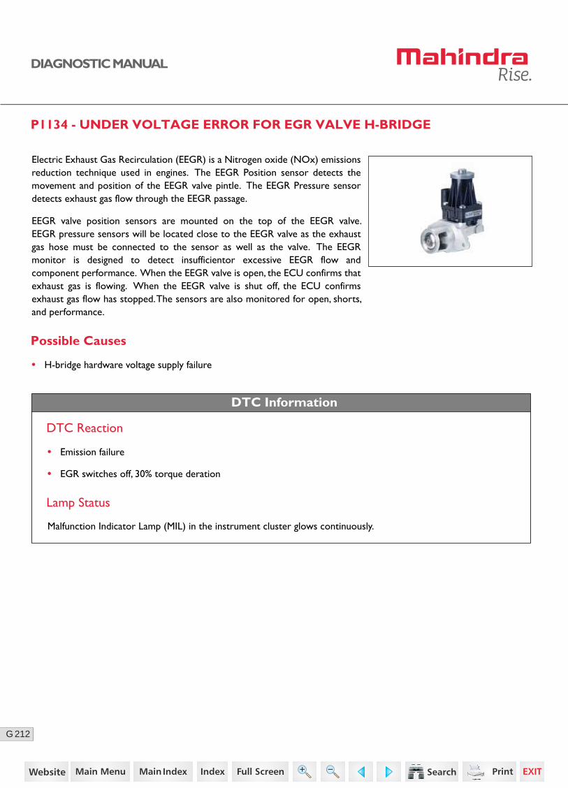
212G
DIAGNOSTIC MANUAL
P1134 - UNDER VOLTAGE ERROR FOR EGR VALVE H-BRIDGE
Possible Causes
Electric Exhaust Gas Recirculation (EEGR) is a Nitrogen oxide (NOx) emissions reduction technique used in engines. The EEGR Position sensor detects the movement and position of the EEGR valve pintle. The EEGR Pressure sensor detects exhaust gas flow through the EEGR passage.
EEGR valve position sensors are mounted on the top of the EEGR valve. EEGR pressure sensors will be located close to the EEGR valve as the exhaust gas hose must be connected to the sensor as well as the valve. The EEGR monitor is designed to detect insufficientor excessive EEGR flow and component performance. When the EEGR valve is open, the ECU confirms that exhaust gas is flowing. When the EEGR valve is shut off, the ECU confirms exhaust gas flow has stopped. The sensors are also monitored for open, shorts, and performance.
• H-bridge hardware voltage supply failure
DTC Information
DTC Reaction
• Emission failure
Lamp Status
Malfunction Indicator Lamp (MIL) in the instrument cluster glows continuously.
• EGR switches off, 30% torque deration
140https://www.truck-manuals.net/

213G
DIAGNOSTIC MANUAL
02
Sensor Location
Connector Pin Details
EGR Valve ECUK85
K37
K58
K15EEGR position sensor - Supply
EEGR actuator motor - Positive
EEGR position sensor - Signal
EEGR position sensor - Ground
EEGR actuator motor - Negative
K84
141https://www.truck-manuals.net/

214G
DIAGNOSTIC MANUAL
Diagnostic Procedure
2 Turn OFF the ignition switch.
Disconnect the EGR and ECU connector.
Check continuity for the following:
• ECU connector pin K84 to EGR connector pin 1
• ECU connector pin K37 to EGR connector pin 2
• ECU connector pin K58 to EGR connector pin 4
• ECU connector pin K85 to EGR connector pin 5
• ECU connector pin K15 to EGR connector pin 6
Go to Step 3
Go to Step 4
Go to Step 5
• Replace the wiring harness.
4 Turn ON the ignition with ECU connector connected.
Check the supply voltage between EGR Connector pin 1 and 5.
3 Check the sensor supply line (pin no. 6), EGR motor +ve (pin no. 1), EGR motor -ve (pin no.5) and EGR position sensor (pin no. 2) is short circuited to ground/battery positive.
Acceptance Criteria
Acceptance Criteria
Voltage = 5 ± 0.2V
Acceptance Criteria
No short circuit to ground/battery positive.
Step Test Procedure Yes No
• Replace the wiring harness.
Ensure proper continuity.
1 Go to Step 2 • Ensure proper fitment.Check for the proper fitment of EGR valve and connec-tor.
• Replace the ECU.
142https://www.truck-manuals.net/
215G
DIAGNOSTIC MANUAL
• Clear the DTC and verify using the FES diagnostic tool.
• Activate the ignition for one driving cycle (ignition-OFF and ON).
After performing the troubleshooting for each P Code, follow the below test procedure before driving the vehicle.
Upon completion of diagnostic procedure, clear the DTC. Ensure that the problem has been rectified and the DTC does not appear again.
Healing Condition
Step Test Procedure Further Action
5Clear the DTC and verify.
If still error repeats,
Replace the EGR with a new one.
143https://www.truck-manuals.net/

216G
DIAGNOSTIC MANUAL
P1135 - OPEN LOAD ERROR FOR EGR VALVE POWERSTAGE
Possible Causes
Electric Exhaust Gas Recirculation (EEGR) is a Nitrogen oxide (NOx) emissions reduction technique used in engines. The EEGR Position sensor detects the movement and position of the EEGR valve pintle. The EEGR Pressure sensor detects exhaust gas flow through the EEGR passage.
EEGR valve position sensors are mounted on the top of the EEGR valve. EEGR pressure sensors will be located close to the EEGR valve as the exhaust gas hose must be connected to the sensor as well as the valve. The EEGR monitor is designed to detect insufficientor excessive EEGR flow and component performance. When the EEGR valve is open, the ECU confirms that exhaust gas is flowing. When the EEGR valve is shut off, the ECU confirms exhaust gas flow has stopped. The sensors are also monitored for open, shorts, and performance.
• Wiring harness problem
• Short circuit to ground
• Faulty EGR Valve
DTC Information
DTC Reaction
• Emission failure
• EGR switches off, 30% torque deration
Lamp Status
Malfunction Indicator Lamp (MIL) in the instrument cluster glows continuously.
144https://www.truck-manuals.net/

217G
DIAGNOSTIC MANUAL
Sensor Location
Connector Pin Details
EGR Valve ECUK85
K37
K58
K15EEGR position sensor - Supply
EEGR actuator motor - Positive
EEGR position sensor - Signal
EEGR position sensor - Ground
EEGR actuator motor - Negative
K84
145https://www.truck-manuals.net/

218G
DIAGNOSTIC MANUAL
Diagnostic Procedure
2 Turn OFF the ignition switch.
Disconnect the EGR and ECU connector.
Check continuity for the following:
• ECU connector pin K84 to EGR connector pin 1
• ECU connector pin K37 to EGR connector pin 2
• ECU connector pin K58 to EGR connector pin 4
• ECU connector pin K85 to EGR connector pin 5
• ECU connector pin K15 to EGR connector pin 6
Go to Step 3
Go to Step 4
Go to Step 5
• Replace the wiring harness.
4 Turn ON the ignition with ECU connector connected.
Check the supply voltage between EGR Connector pin 1 and 5.
3 Check the sensor supply line (pin no. 6), EGR motor +ve (pin no. 1), EGR motor -ve (pin no.5) and EGR position sensor (pin no. 2) is short circuited to ground/battery positive.
Acceptance Criteria
Acceptance Criteria
Voltage = 5 ± 0.2V
Acceptance Criteria
No short circuit to ground/battery positive.
Step Test Procedure Yes No
• Replace the wiring harness.
Ensure proper continuity.
1 Go to Step 2 • Ensure proper fitment.Check for the proper fitment of EGR valve and connec-tor.
• Replace the ECU.
146https://www.truck-manuals.net/

219G
DIAGNOSTIC MANUAL
• Clear the DTC and verify using the FES diagnostic tool.
• Activate the ignition for one driving cycle (ignition-OFF and ON).
After performing the troubleshooting for each P Code, follow the below test procedure before driving the vehicle.
Upon completion of diagnostic procedure, clear the DTC. Ensure that the problem has been rectified and the DTC does not appear again.
Healing Condition
Step Test Procedure Further Action
5Clear the DTC and verify.
If still error repeats,
Replace the EGR with a new one.
147https://www.truck-manuals.net/
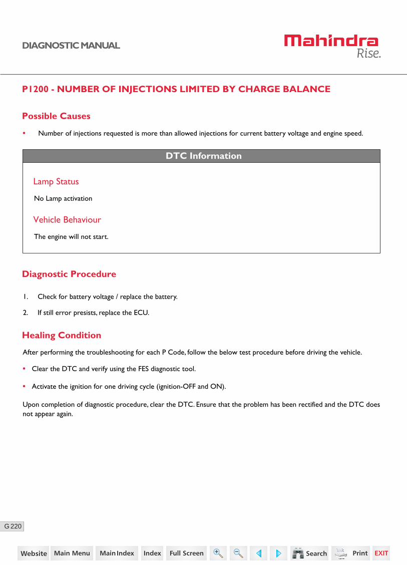
220G
DIAGNOSTIC MANUAL
P1200 - NUMBER OF INJECTIONS LIMITED BY CHARGE BALANCE
Possible Causes
• Number of injections requested is more than allowed injections for current battery voltage and engine speed.
DTC Information
Lamp Status
No Lamp activation
Vehicle Behaviour
The engine will not start.
Diagnostic Procedure
1. Check for battery voltage / replace the battery.
2. If still error presists, replace the ECU.
• Clear the DTC and verify using the FES diagnostic tool.
• Activate the ignition for one driving cycle (ignition-OFF and ON).
Healing Condition
After performing the troubleshooting for each P Code, follow the below test procedure before driving the vehicle.
Upon completion of diagnostic procedure, clear the DTC. Ensure that the problem has been rectified and the DTC does not appear again.
148https://www.truck-manuals.net/
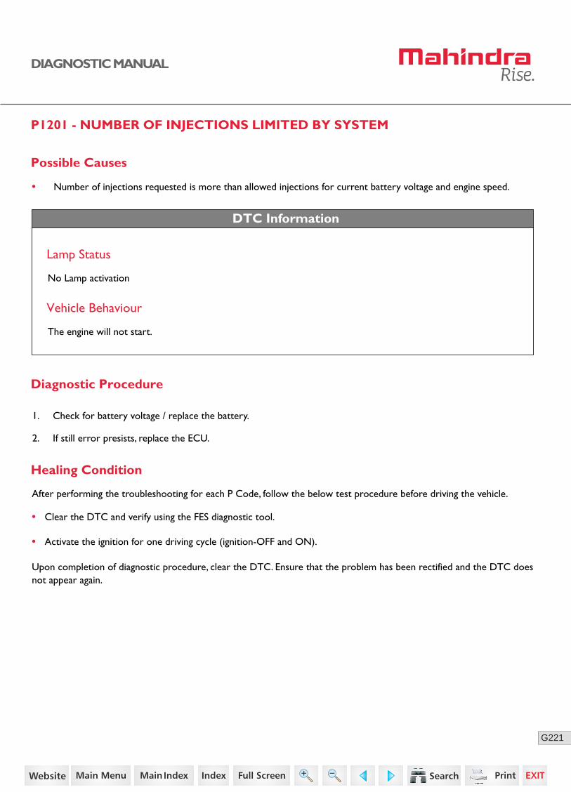
221G
DIAGNOSTIC MANUAL
P1201 - NUMBER OF INJECTIONS LIMITED BY SYSTEM
Possible Causes
• Number of injections requested is more than allowed injections for current battery voltage and engine speed.
DTC Information
Lamp Status
No Lamp activation
Vehicle Behaviour
The engine will not start.
Diagnostic Procedure
1. Check for battery voltage / replace the battery.
2. If still error presists, replace the ECU.
• Clear the DTC and verify using the FES diagnostic tool.
• Activate the ignition for one driving cycle (ignition-OFF and ON).
Healing Condition
After performing the troubleshooting for each P Code, follow the below test procedure before driving the vehicle.
Upon completion of diagnostic procedure, clear the DTC. Ensure that the problem has been rectified and the DTC does not appear again.
149https://www.truck-manuals.net/
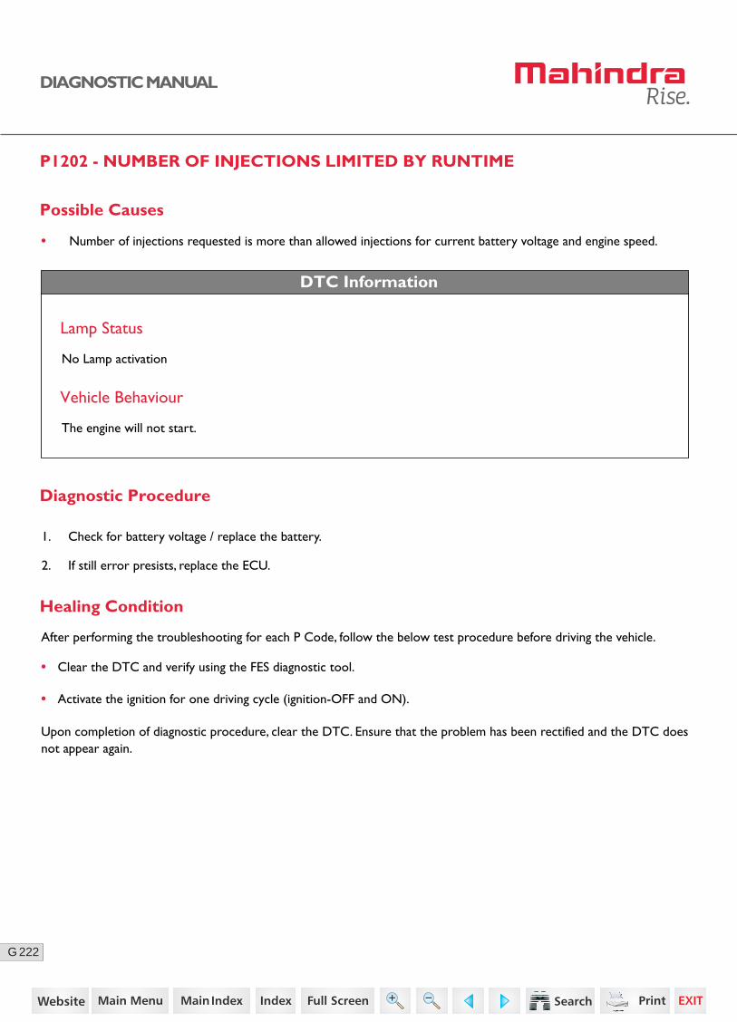
222G
DIAGNOSTIC MANUAL
P1202 - NUMBER OF INJECTIONS LIMITED BY RUNTIME
Possible Causes
• Number of injections requested is more than allowed injections for current battery voltage and engine speed.
DTC Information
Lamp Status
No Lamp activation
Vehicle Behaviour
The engine will not start.
Diagnostic Procedure
1. Check for battery voltage / replace the battery.
2. If still error presists, replace the ECU.
• Clear the DTC and verify using the FES diagnostic tool.
• Activate the ignition for one driving cycle (ignition-OFF and ON).
Healing Condition
After performing the troubleshooting for each P Code, follow the below test procedure before driving the vehicle.
Upon completion of diagnostic procedure, clear the DTC. Ensure that the problem has been rectified and the DTC does not appear again.
150https://www.truck-manuals.net/
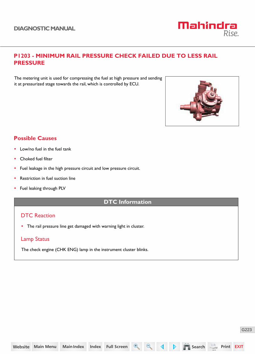
223G
DIAGNOSTIC MANUAL
P1203 - MINIMUM RAIL PRESSURE CHECK FAILED DUE TO LESS RAIL PRESSURE
The metering unit is used for compressing the fuel at high pressure and sending it at pressurized stage towards the rail, which is controlled by ECU.
Possible Causes
• Low/no fuel in the fuel tank
• Choked fuel filter
• Fuel leakage in the high pressure circuit and low pressure circuit.
• Restriction in fuel suction line
• Fuel leaking through PLV
DTC Information
DTC Reaction
• The rail pressure line get damaged with warning light in cluster.
Lamp Status
The check engine (CHK ENG) lamp in the instrument cluster blinks.
151https://www.truck-manuals.net/

224G
DIAGNOSTIC MANUAL
Metering Unit Location
Connector Pin Details
Fuel Metering Unit SensorECU
K89Fuel metering unit
Power supply
30
5 A
86 85
87
Main Relay
152https://www.truck-manuals.net/
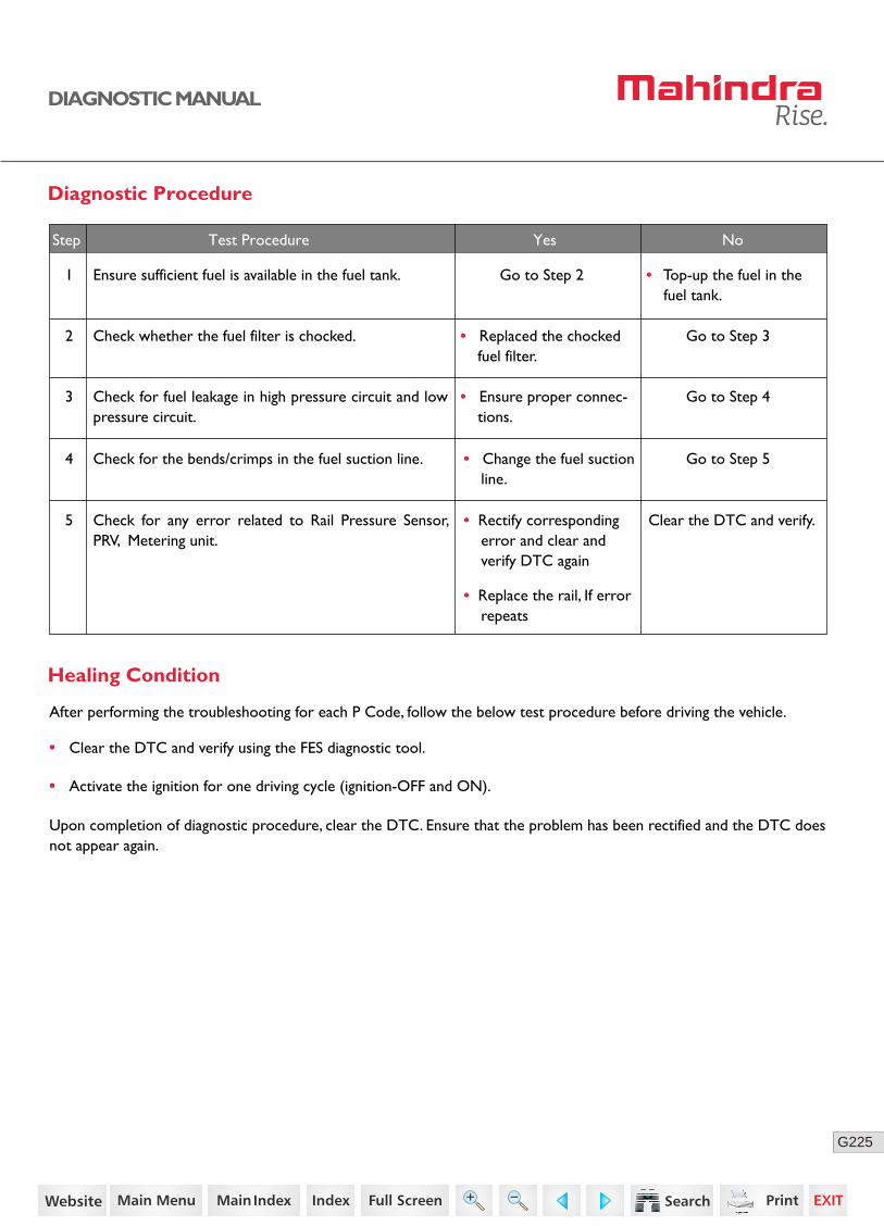
225G
DIAGNOSTIC MANUAL
Diagnostic Procedure
1 Ensure sufficient fuel is available in the fuel tank. Go to Step 2 • Top-up the fuel in the fuel tank.
2 Check whether the fuel filter is chocked. Go to Step 3• Replaced the chocked fuel filter.
3 Check for fuel leakage in high pressure circuit and low pressure circuit.
Go to Step 4• Ensure proper connec-tions.
4 Check for the bends/crimps in the fuel suction line. Go to Step 5• Change the fuel suction line.
5 Clear the DTC and verify.
Step Test Procedure Yes No
• Clear the DTC and verify using the FES diagnostic tool.
• Activate the ignition for one driving cycle (ignition-OFF and ON).
Healing Condition
After performing the troubleshooting for each P Code, follow the below test procedure before driving the vehicle.
Upon completion of diagnostic procedure, clear the DTC. Ensure that the problem has been rectified and the DTC does not appear again.
Check for any error related to Rail Pressure Sensor, PRV, Metering unit.
• Rectify corresponding error and clear and verify DTC again
• Replace the rail, If error repeats
153https://www.truck-manuals.net/
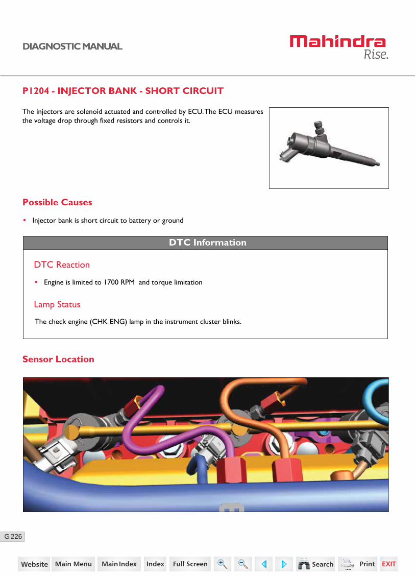
226G
DIAGNOSTIC MANUAL
P1204 - INJECTOR BANK - SHORT CIRCUIT
DTC Information
DTC Reaction
• Engine is limited to 1700 RPM and torque limitation
Lamp Status
The check engine (CHK ENG) lamp in the instrument cluster blinks.
Possible Causes
• Injector bank is short circuit to battery or ground
Sensor Location
The injectors are solenoid actuated and controlled by ECU. The ECU measures the voltage drop through fixed resistors and controls it.
154https://www.truck-manuals.net/
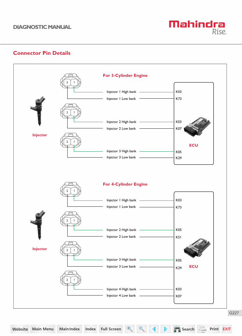
227G
DIAGNOSTIC MANUAL
Connector Pin Details
For 3-Cylinder Engine
For 4-Cylinder Engine
ECU
Injector
K73
K03Injector 1 High bank
Injector 1 Low bank
2 1
K07
K03Injector 2 High bank
Injector 2 Low bank
2 1
K29
K05Injector 3 High bank
Injector 3 Low bank
2 1
ECU
Injector
K73
K03Injector 1 High bank
Injector 1 Low bank
2 1
K51
K05Injector 2 High bank
Injector 2 Low bank
2 1
K29
K05Injector 3 High bank
Injector 3 Low bank
2 1
K07
K03Injector 4 High bank
Injector 4 Low bank
2 1
155https://www.truck-manuals.net/

228G
DIAGNOSTIC MANUAL
Diagnostic Procedure
1 Turn OFF the ignition switch.
Disconnect the injector connector and ECU connector.
Check continuity for the following:
For 4-Cylinder Engine
For 3-Cylinder Engine
Go to Step 2
Acceptance Criteria
Ensure proper continuity.
Step Test Procedure Yes No
• Replace the wiring harness.
• ECU connector pins K03 and 1st injector connector pin 1
• ECU connector pins K73 and 1st injector connector pin 2
• ECU connector pins K03 and 2nd injector connector pin 1
• ECU connector pins K07 and 2nd injector connector pin 2
• ECU connector pins K05 and 3rd injector connector pin 1
• ECU connector pins K51 and 3rd injector connector pin 2
• ECU connector pins K05 and 4th injector connector pin 1
• ECU connector pins K29 and 4th injector connector pin 2
• ECU connector pins K03 and 1st injector connector pin 1
• ECU connector pins K73 and 1st injector connector pin 2
• ECU connector pins K03 and 2nd injector connector pin 1
• ECU connector pins K07 and 2nd injector connector pin 2
• ECU connector pins K05 and 3rd injector connector pin 1
• ECU connector pins K29 and 3rd injector connector pin 2
156https://www.truck-manuals.net/
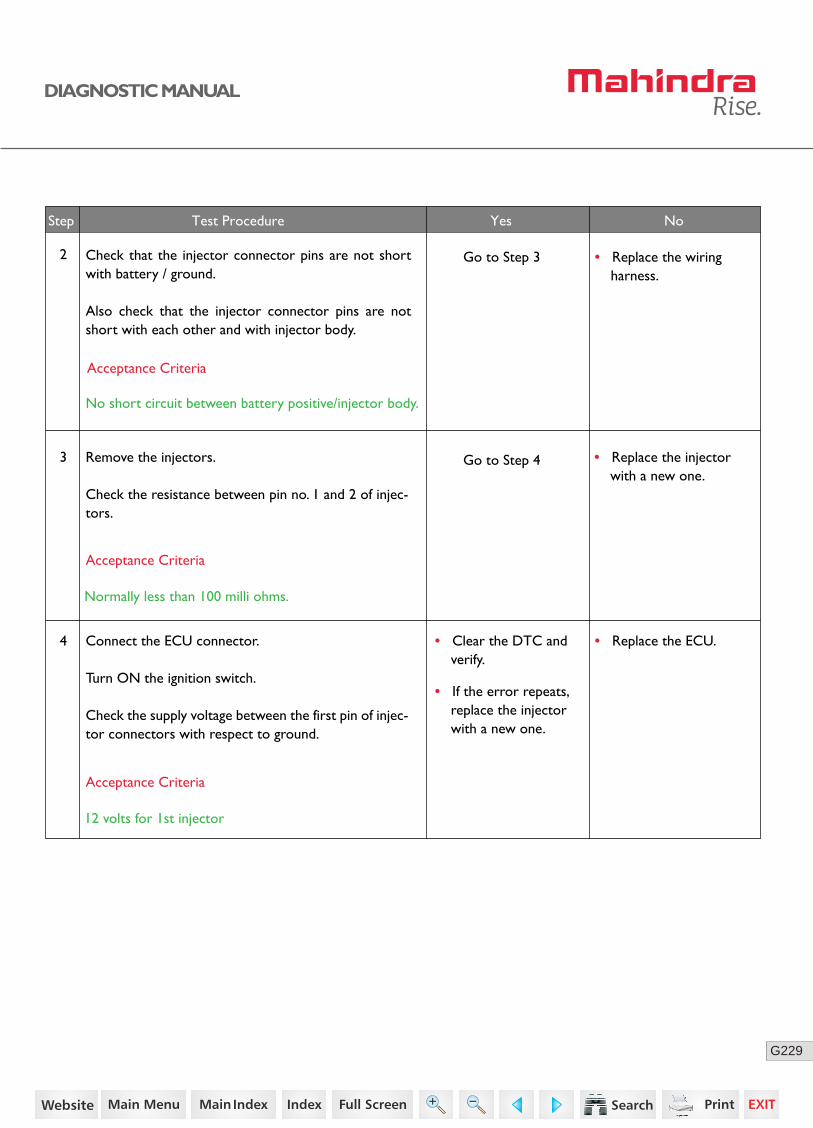
229G
DIAGNOSTIC MANUAL
No
• Replace the injector with a new one.
3 Remove the injectors.
Check the resistance between pin no. 1 and 2 of injec-tors.
2
Acceptance Criteria
Normally less than 100 milli ohms.
NoStep Test Procedure Yes No
• Replace the ECU.• Clear the DTC and verify.
• If the error repeats, replace the injector with a new one.
4 Connect the ECU connector.
Turn ON the ignition switch.
Check the supply voltage between the first pin of injec-tor connectors with respect to ground.
Acceptance Criteria
12 volts for 1st injector
Check that the injector connector pins are not short with battery / ground.
Also check that the injector connector pins are not short with each other and with injector body.
Acceptance Criteria
No short circuit between battery positive/injector body.
• Replace the wiring harness.
Go to Step 3
Go to Step 4
157https://www.truck-manuals.net/
230G
DIAGNOSTIC MANUAL
• Clear the DTC and verify using the FES diagnostic tool.
• Activate the ignition for one driving cycle (ignition-OFF and ON).
Healing Condition
After performing the troubleshooting for each P Code, follow the below test procedure before driving the vehicle.
Upon completion of diagnostic procedure, clear the DTC. Ensure that the problem has been rectified and the DTC does not appear again.
158https://www.truck-manuals.net/
231G
DIAGNOSTIC MANUAL
P1206 - INJECTOR CHIP ERROR
Possible Causes
• CY33x chip is defective.
• CY33x chip is damaged.
DTC Information
DTC Reaction
Engine shut-off
1. Switch ON and OFF the ignition key (with complete after run).
2. Clear the error.
3. Try the above step once again.
4. Still error is present, Replace the ECU.
Lamp Status
The check engine (CHK ENG) lamp in the instrument cluster glows continuously.
Diagnostic Procedure
• Clear the DTC and verify using the FES diagnostic tool.
• Activate the ignition for one driving cycle (ignition-OFF and ON).
Healing Condition
After performing the troubleshooting for each P Code, follow the below test procedure before driving the vehicle.
Upon completion of diagnostic procedure, clear the DTC. Ensure that the problem has been rectified and the DTC does not appear again.
159https://www.truck-manuals.net/
232G
DIAGNOSTIC MANUAL
P1221 - CHECK OF MISSING INJECTOR ADJUSTMENT VALUE PROGRAMMING
Possible Causes
• The checksum of the injector 1 adjustment code words is not correct/not flashed during end of line station.
• The basic correction quantity in at least one injector checkpoint has exceeded the admissible limits
• No injector adjustment values could be read due to faulty EEPROM access.
DTC Information
DTC Reaction
• Injector misses the functioning of IQA
1. Connect the FES diagnostic tool.
2. Click on the Write data tab.
3. Check for Injector numbers.
4. Note the injector numbers from engine and write it through the diagnostic tester tool, If the numbers are missing.
Lamp Status
The check engine (CHK ENG) lamp in the instrument cluster blinks.
Diagnostic Procedure
• Clear the DTC and verify using the FES diagnostic tool.
• Activate the ignition for one driving cycle (ignition-OFF and ON).
Healing Condition
After performing the troubleshooting for each P Code, follow the below test procedure before driving the vehicle.
Upon completion of diagnostic procedure, clear the DTC. Ensure that the problem has been rectified and the DTC does not appear again.
160https://www.truck-manuals.net/
233G
DIAGNOSTIC MANUAL
P1222 - CHECK OF MISSING INJECTOR ADJUSTMENT VALUE PROGRAMMING
Possible Causes
• The checksum of the injector 3 adjustment code words is not correct/not flashed during end of line station.
• The basic correction quantity in at least one injector checkpoint has exceeded the admissible limits
• No injector adjustment values could be read due to faulty EEPROM access.
DTC Information
DTC Reaction
• Injector misses the functioning of IQA
Lamp Status
The check engine (CHK ENG) lamp in the instrument cluster blinks.
1. Connect the FES diagnostic tool.
2. Click on the Write data tab.
3. Check for Injector numbers.
4. Note the injector numbers from engine and write it through the diagnostic tester tool, If the numbers are missing.
Diagnostic Procedure
• Clear the DTC and verify using the FES diagnostic tool.
• Activate the ignition for one driving cycle (ignition-OFF and ON).
Healing Condition
After performing the troubleshooting for each P Code, follow the below test procedure before driving the vehicle.
Upon completion of diagnostic procedure, clear the DTC. Ensure that the problem has been rectified and the DTC does not appear again.
161https://www.truck-manuals.net/

234G
DIAGNOSTIC MANUAL
P1223 - CHECK OF MISSING INJECTOR ADJUSTMENT VALUE PROGRAMMING
Possible Causes
• The checksum of the injector 4 adjustment code words is not correct/not flashed during end of line station.
• The basic correction quantity in at least one injector checkpoint has exceeded the admissible limits
• No injector adjustment values could be read due to faulty EEPROM access.
DTC Information
DTC Reaction
• Injector misses the functioning of IQA
Lamp Status
The check engine (CHK ENG) lamp in the instrument cluster blinks.
1. Connect the FES diagnostic tool.
2. Click on the Write data tab.
3. Check for Injector numbers.
4. Note the injector numbers from engine and write it through the diagnostic tester tool, If the numbers are missing.
Diagnostic Procedure
• Clear the DTC and verify using the FES diagnostic tool.
• Activate the ignition for one driving cycle (ignition-OFF and ON).
Healing Condition
After performing the troubleshooting for each P Code, follow the below test procedure before driving the vehicle.
Upon completion of diagnostic procedure, clear the DTC. Ensure that the problem has been rectified and the DTC does not appear again.
162https://www.truck-manuals.net/
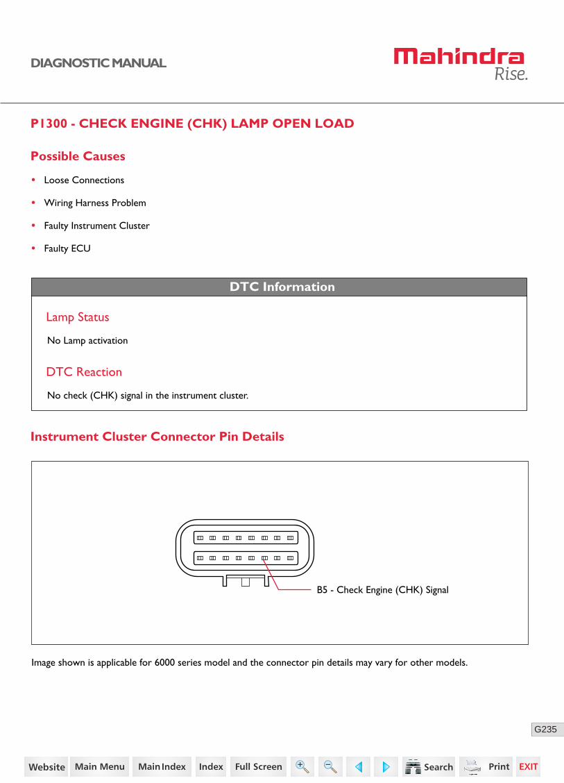
235G
DIAGNOSTIC MANUAL
P1300 - CHECK ENGINE (CHK) LAMP OPEN LOAD
Possible Causes
• Loose Connections
• Wiring Harness Problem
• Faulty Instrument Cluster
• Faulty ECU
DTC Information
DTC Reaction
No check (CHK) signal in the instrument cluster.
B5 - Check Engine (CHK) Signal
Lamp Status
No Lamp activation
Instrument Cluster Connector Pin Details
Image shown is applicable for 6000 series model and the connector pin details may vary for other models.
163https://www.truck-manuals.net/

236G
DIAGNOSTIC MANUAL
3
• Clear the DTC and verify.
• If the error repeats, replace the cluster with a new one.
No
• Clear the DTC and verify using the FES diagnostic tool.
• Activate the ignition for one driving cycle (ignition-OFF and ON).
Healing Condition
After performing the troubleshooting for each P Code, follow the below test procedure before driving the vehicle.
Upon completion of diagnostic procedure, clear the DTC. Ensure that the problem has been rectified and the DTC does not appear again.
Diagnostic Procedure
2 Turn OFF the ignition switch.
Disconnect the ECU connector and instrument cluster connector.
Check the continuity between ECU connector pin K93 and instrument cluster connector pin B5.
• Replace the wiring harness.
1 Check whether the instrument cluster is connected to ECU.
Go to Step 2 • Ensure better connec-tions.
Acceptance Criteria
Ensure proper continuity.
Step Test Procedure Yes No
If still error repeats,
Replace the ECU with a new one.Clear the DTC and verify.
164https://www.truck-manuals.net/
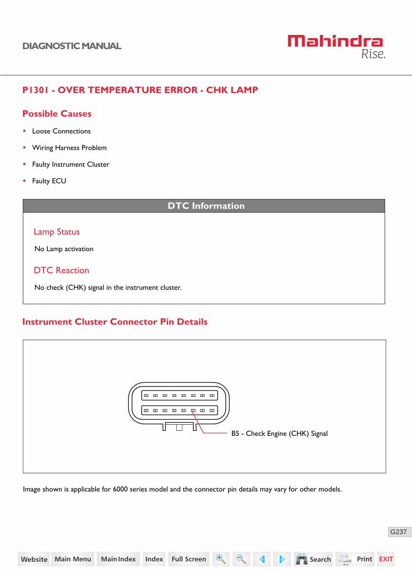
237G
DIAGNOSTIC MANUAL
P1301 - OVER TEMPERATURE ERROR - CHK LAMP
DTC Information
Lamp Status
No Lamp activation
DTC Reaction
No check (CHK) signal in the instrument cluster.
Possible Causes
• Loose Connections
• Wiring Harness Problem
• Faulty Instrument Cluster
• Faulty ECU
B5 - Check Engine (CHK) Signal
Instrument Cluster Connector Pin Details
Image shown is applicable for 6000 series model and the connector pin details may vary for other models.
165https://www.truck-manuals.net/

238G
DIAGNOSTIC MANUAL
3 Connect the ECU connector.
Turn ON the ignition.
Check for any short circuit between instrument cluster connector pin B5 with ground / battery.
• Replace the wiring harness.
No
Diagnostic Procedure
2 Turn OFF the ignition switch.
Disconnect the ECU connector and instrument cluster connector.
Check the continuity between ECU connector pin K93 and instrument cluster connector pin B5.
• Replace the wiring harness.
1 Check whether the instrument cluster is connected to ECU.
Go to Step 2 • Ensure better connec-tions.
Acceptance Criteria
Ensure proper continuity.
Step Test Procedure Yes No
Go to Step 3
Acceptance Criteria
No short circuit between ground / battery.
4
• Clear the DTC and verify.
• If the error repeats, replace the cluster with a new one.
If still error repeats,
Replace the ECU with a new one.Clear the DTC and verify.
• Clear the DTC and verify using the FES diagnostic tool.
• Activate the ignition for one driving cycle (ignition-OFF and ON).
Healing Condition
After performing the troubleshooting for each P Code, follow the below test procedure before driving the vehicle.
Upon completion of diagnostic procedure, clear the DTC. Ensure that the problem has been rectified and the DTC does not appear again.
166https://www.truck-manuals.net/
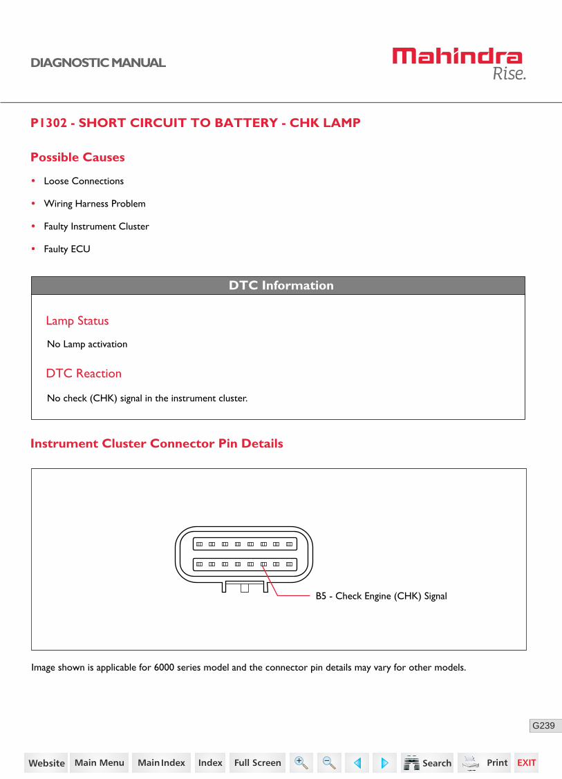
239G
DIAGNOSTIC MANUAL
P1302 - SHORT CIRCUIT TO BATTERY - CHK LAMP
DTC Information
Lamp Status
No Lamp activation
DTC Reaction
B5 - Check Engine (CHK) Signal
Instrument Cluster Connector Pin Details
Possible Causes
• Loose Connections
• Wiring Harness Problem
• Faulty Instrument Cluster
• Faulty ECU
No check (CHK) signal in the instrument cluster.
Image shown is applicable for 6000 series model and the connector pin details may vary for other models.
167https://www.truck-manuals.net/

240G
DIAGNOSTIC MANUAL
3 Connect the ECU connector.
Turn ON the ignition.
Check for any short circuit between instrument cluster connector pin B5 with ground / battery.
• Replace the wiring harness.
No
Diagnostic Procedure
2 Turn OFF the ignition switch.
Disconnect the ECU connector and instrument cluster connector.
Check the continuity between ECU connector pin K93 and instrument cluster connector pin B5.
• Replace the wiring harness.
1 Check whether the instrument cluster is connected to ECU.
Go to Step 2 • Ensure better connec-tions.
Acceptance Criteria
Ensure proper continuity.
Step Test Procedure Yes No
Go to Step 3
Acceptance Criteria
No short circuit between ground / battery.
4
• Clear the DTC and verify.
• If the error repeats, replace the cluster with a new one.
If still error repeats,
Replace the ECU with a new one.Clear the DTC and verify.
• Clear the DTC and verify using the FES diagnostic tool.
• Activate the ignition for one driving cycle (ignition-OFF and ON).
Healing Condition
After performing the troubleshooting for each P Code, follow the below test procedure before driving the vehicle.
Upon completion of diagnostic procedure, clear the DTC. Ensure that the problem has been rectified and the DTC does not appear again.
168https://www.truck-manuals.net/
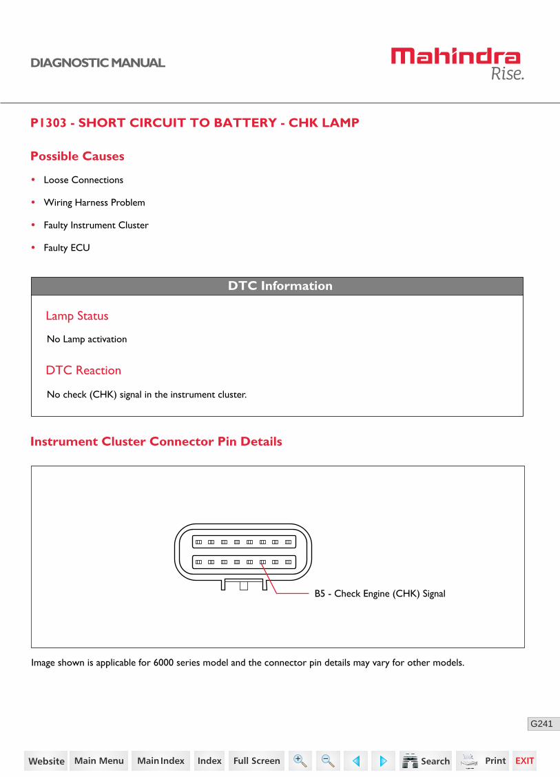
241G
DIAGNOSTIC MANUAL
P1303 - SHORT CIRCUIT TO BATTERY - CHK LAMP
Possible Causes
• Loose Connections
• Wiring Harness Problem
• Faulty Instrument Cluster
• Faulty ECU
DTC Information
DTC Reaction
Lamp Status
No Lamp activation
B5 - Check Engine (CHK) Signal
Instrument Cluster Connector Pin Details
No check (CHK) signal in the instrument cluster.
Image shown is applicable for 6000 series model and the connector pin details may vary for other models.
169https://www.truck-manuals.net/

242G
DIAGNOSTIC MANUAL
3 Connect the ECU connector.
Turn ON the ignition.
Check for any short circuit between instrument cluster connector pin B5 with ground / battery.
• Replace the wiring harness.
Diagnostic Procedure
2 Turn OFF the ignition switch.
Disconnect the ECU connector and instrument cluster connector.
Check the continuity between ECU connector pin K93 and instrument cluster connector pin B5.
• Replace the wiring harness.
1 Check whether the instrument cluster is connected to ECU.
Go to Step 2 • Ensure better connec-tions.
Acceptance Criteria
Ensure proper continuity.
Step Test Procedure Yes
Go to Step 3
Acceptance Criteria
No short circuit between ground / battery.
4
• Clear the DTC and verify.
• If the error repeats, replace the cluster with a new one.
If still error repeats,
Replace the ECU with a new one.Clear the DTC and verify.
• Clear the DTC and verify using the FES diagnostic tool.
• Activate the ignition for one driving cycle (ignition-OFF and ON).
Healing Condition
After performing the troubleshooting for each P Code, follow the below test procedure before driving the vehicle.
Upon completion of diagnostic procedure, clear the DTC. Ensure that the problem has been rectified and the DTC does not appear again.
170https://www.truck-manuals.net/
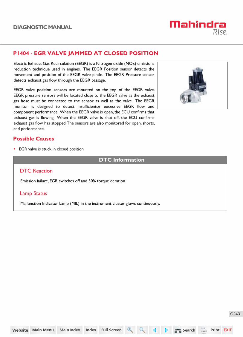
243G
DIAGNOSTIC MANUAL
P1404 - EGR VALVE JAMMED AT CLOSED POSITION
Possible Causes
Electric Exhaust Gas Recirculation (EEGR) is a Nitrogen oxide (NOx) emissions reduction technique used in engines. The EEGR Position sensor detects the movement and position of the EEGR valve pintle. The EEGR Pressure sensor detects exhaust gas flow through the EEGR passage.
EEGR valve position sensors are mounted on the top of the EEGR valve. EEGR pressure sensors will be located close to the EEGR valve as the exhaust gas hose must be connected to the sensor as well as the valve. The EEGR monitor is designed to detect insufficientor excessive EEGR flow and component performance. When the EEGR valve is open, the ECU confirms that exhaust gas is flowing. When the EEGR valve is shut off, the ECU confirms exhaust gas flow has stopped. The sensors are also monitored for open, shorts, and performance.
• EGR valve is stuck in closed position
DTC Information
DTC Reaction
Lamp Status
Malfunction Indicator Lamp (MIL) in the instrument cluster glows continuously.
Emission failure, EGR switches off and 30% torque deration
171https://www.truck-manuals.net/

244G
DIAGNOSTIC MANUAL
Connector Pin Details
EGR Valve ECUK85
K37
K58
K15EEGR position sensor - Supply
EEGR actuator motor - Positive
EEGR position sensor - Signal
EEGR position sensor - Ground
EEGR actuator motor - Negative
K84
Sensor Location
172https://www.truck-manuals.net/
245G
DIAGNOSTIC MANUAL
Diagnostic Procedure
1. Activate the EGR through FES diagnostic tool actuator service.
2. If positive response comes, clear the DTC and run the tractor at 2100 RPM for 15min.
3. If error repeats, replace the EGR valve.
• Clear the DTC and verify using the FES diagnostic tool.
• Activate the ignition for one driving cycle (ignition-OFF and ON).
Healing Condition
After performing the troubleshooting for each P Code, follow the below test procedure before driving the vehicle.
Upon completion of diagnostic procedure, clear the DTC. Ensure that the problem has been rectified and the DTC does not appear again.
173https://www.truck-manuals.net/

246G
DIAGNOSTIC MANUAL
P1413 - EGR VALVE JAMMED AT OPEN POSITION
Possible Causes
Electric Exhaust Gas Recirculation (EEGR) is a Nitrogen oxide (NOx) emissions reduction technique used in engines. The EEGR Position sensor detects the movement and position of the EEGR valve pintle. The EEGR Pressure sensor detects exhaust gas flow through the EEGR passage.
EEGR valve position sensors are mounted on the top of the EEGR valve. EEGR pressure sensors will be located close to the EEGR valve as the exhaust gas hose must be connected to the sensor as well as the valve. The EEGR monitor is designed to detect insufficientor excessive EEGR flow and component performance. When the EEGR valve is open, the ECU confirms that exhaust gas is flowing. When the EEGR valve is shut off, the ECU confirms exhaust gas flow has stopped. The sensors are also monitored for open, shorts, and performance.
• EGR valve is stuck in open position
DTC Information
DTC Reaction
Lamp Status
Malfunction Indicator Lamp (MIL) in the instrument cluster glows continuously.
Sensor Location
Emission failure, EGR switches off and 30% torque deration
174https://www.truck-manuals.net/

247G
DIAGNOSTIC MANUAL
Connector Pin Details
EGR Valve ECUK85
K37
K58
K15EEGR position sensor - Supply
EEGR actuator motor - Positive
EEGR position sensor - Signal
EEGR position sensor - Ground
EEGR actuator motor - Negative
K84
Diagnostic Procedure
• Clear the DTC and verify using the FES diagnostic tool.
• Activate the ignition for one driving cycle (ignition-OFF and ON).
Healing Condition
After performing the troubleshooting for each P Code, follow the below test procedure before driving the vehicle.
Upon completion of diagnostic procedure, clear the DTC. Ensure that the problem has been rectified and the DTC does not appear again.
1. Activate the EGR through FES diagnostic tool actuator service.
2. If positive response comes, clear the DTC and run the tractor at 2100 RPM for 15min.
3. If error repeats, replace the EGR valve.
175https://www.truck-manuals.net/

248G
DIAGNOSTIC MANUAL
P1416 - LOOSE CONTACT BETWEEN METERING UNIT AND ECU
The metering unit is used for compressing the fuel at high pressure and sending it at pressurized stage towards the rail, which is controlled by ECU.
Possible Causes
• Loose connections
• Wiring harness problem
DTC Information
DTC Reaction
• The rail pressure line get damaged with warning light in cluster.
Lamp Status
The check engine (CHK ENG) lamp in the instrument cluster blinks.
Metering Unit Location
176https://www.truck-manuals.net/
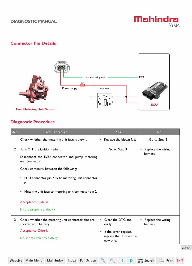
249G
DIAGNOSTIC MANUAL
Connector Pin Details
Diagnostic Procedure
1 Check whether the metering unit fuse is blown.
Check whether the metering unit connector pins are shorted with battery.
Go to Step 2
Go to Step 3
• Replace the blown fuse.
Step Test Procedure Yes No
2
3
Turn OFF the ignition switch.
Disconnect the ECU connector and pump metering unit connector.
Check continuity between the following:
• Replace the wiring harness.
• ECU connector pin K89 to metering unit connector pin 1.
• Metering unit fuse to metering unit connector pin 2.
Acceptance Criteria
Ensure proper continuity.
Acceptance Criteria
No short circuit to battery.
Fuel Metering Unit SensorECU
K89Fuel metering unit
Power supply
30
5 A
86 85
87
Main Relay
• Replace the wiring harness.
• Clear the DTC and verify.
• If the error repeats, replace the ECU with a new one.
177https://www.truck-manuals.net/

250G
DIAGNOSTIC MANUAL
• Clear the DTC and verify using the FES diagnostic tool.
• Activate the ignition for one driving cycle (ignition-OFF and ON).
Healing Condition
After performing the troubleshooting for each P Code, follow the below test procedure before driving the vehicle.
Upon completion of diagnostic procedure, clear the DTC. Ensure that the problem has been rectified and the DTC does not appear again.
178https://www.truck-manuals.net/

251G
DIAGNOSTIC MANUAL
P1417 - OVER TEMPERATURE OF DEVICE DRIVER OF METERING UNIT
The metering unit is used for compressing the fuel at high pressure and sending it at pressurized stage towards the rail, which is controlled by ECU.
Possible Causes
• Pump metering unit short circuit to battery/ground for long time.
• Wiring harness problem
DTC Information
DTC Reaction
• The rail pressure line get damaged with warning light in cluster.
Lamp Status
The check engine (CHK ENG) lamp in the instrument cluster blinks.
Metering Unit Location
179https://www.truck-manuals.net/
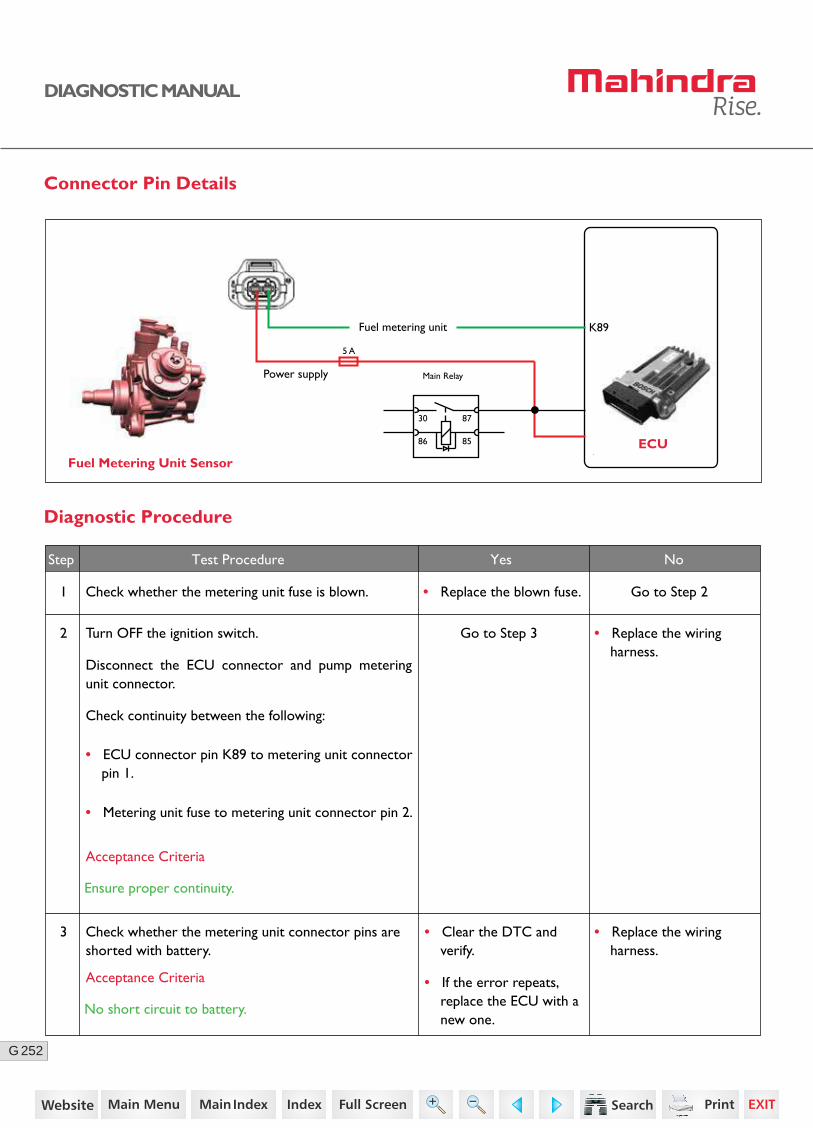
252G
DIAGNOSTIC MANUAL
Connector Pin Details
Diagnostic Procedure
1 Check whether the metering unit fuse is blown.
Check whether the metering unit connector pins are shorted with battery.
Go to Step 2
Go to Step 3
• Replace the blown fuse.
Step Test Procedure Yes No
2
3
Turn OFF the ignition switch.
Disconnect the ECU connector and pump metering unit connector.
Check continuity between the following:
• Replace the wiring harness.
• Replace the wiring harness.
• Clear the DTC and verify.
• If the error repeats, replace the ECU with a new one.
• ECU connector pin K89 to metering unit connector pin 1.
• Metering unit fuse to metering unit connector pin 2.
Acceptance Criteria
Ensure proper continuity.
Acceptance Criteria
No short circuit to battery.
Fuel Metering Unit SensorECU
K89Fuel metering unit
Power supply
30
5 A
86 85
87
Main Relay
180https://www.truck-manuals.net/

253G
DIAGNOSTIC MANUAL
• Clear the DTC and verify using the FES diagnostic tool.
• Activate the ignition for one driving cycle (ignition-OFF and ON).
Healing Condition
After performing the troubleshooting for each P Code, follow the below test procedure before driving the vehicle.
Upon completion of diagnostic procedure, clear the DTC. Ensure that the problem has been rectified and the DTC does not appear again.
181https://www.truck-manuals.net/
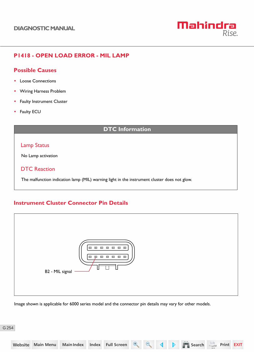
254G
DIAGNOSTIC MANUAL
P1418 - OPEN LOAD ERROR - MIL LAMP
DTC Information
Lamp Status
No Lamp activation
DTC Reaction
The malfunction indication lamp (MIL) warning light in the instrument cluster does not glow.
Possible Causes
• Loose Connections
• Wiring Harness Problem
• Faulty Instrument Cluster
• Faulty ECU
B2 - MIL signal
Instrument Cluster Connector Pin Details
Image shown is applicable for 6000 series model and the connector pin details may vary for other models.
182https://www.truck-manuals.net/
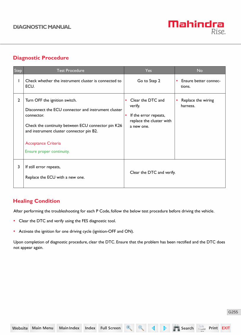
255G
DIAGNOSTIC MANUAL
3
• Clear the DTC and verify.
• If the error repeats, replace the cluster with a new one.
No
• Clear the DTC and verify using the FES diagnostic tool.
• Activate the ignition for one driving cycle (ignition-OFF and ON).
Healing Condition
After performing the troubleshooting for each P Code, follow the below test procedure before driving the vehicle.
Upon completion of diagnostic procedure, clear the DTC. Ensure that the problem has been rectified and the DTC does not appear again.
Diagnostic Procedure
2 Turn OFF the ignition switch.
Disconnect the ECU connector and instrument cluster connector.
Check the continuity between ECU connector pin K26 and instrument cluster connector pin B2.
• Replace the wiring harness.
1 Check whether the instrument cluster is connected to ECU.
Go to Step 2 • Ensure better connec-tions.
Acceptance Criteria
Ensure proper continuity.
Step Test Procedure Yes No
If still error repeats,
Replace the ECU with a new one.Clear the DTC and verify.
183https://www.truck-manuals.net/
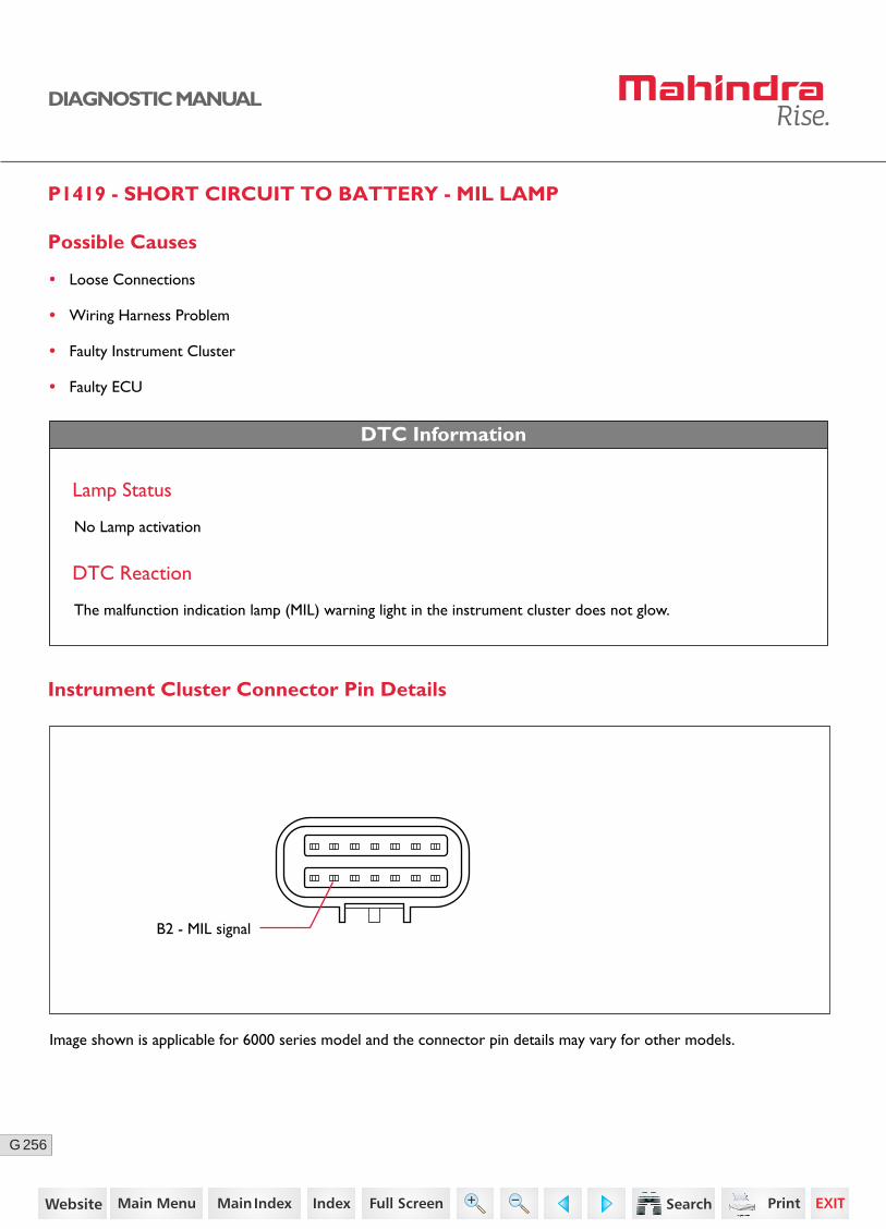
256G
DIAGNOSTIC MANUAL
P1419 - SHORT CIRCUIT TO BATTERY - MIL LAMP
DTC Information
Lamp Status
No Lamp activation
DTC Reaction
The malfunction indication lamp (MIL) warning light in the instrument cluster does not glow.
Possible Causes
• Loose Connections
• Wiring Harness Problem
• Faulty Instrument Cluster
• Faulty ECU
B2 - MIL signal
Instrument Cluster Connector Pin Details
Image shown is applicable for 6000 series model and the connector pin details may vary for other models.
184https://www.truck-manuals.net/

257G
DIAGNOSTIC MANUAL
3 Connect the ECU connector.
Turn ON the ignition.
Check for any short circuit between instrument cluster connector pin B2 with ground / battery.
• Replace the wiring harness.
No
Diagnostic Procedure
2 Turn OFF the ignition switch.
Disconnect the ECU connector and instrument cluster connector.
Check the continuity between ECU connector pin K26 and instrument cluster connector pin B2.
• Replace the wiring harness.
1 Check whether the instrument cluster is connected to ECU.
Go to Step 2 • Ensure better connec-tions.
Acceptance Criteria
Ensure proper continuity.
Step Test Procedure Yes No
Go to Step 3
Acceptance Criteria
No short circuit between ground / battery.
4
• Clear the DTC and verify.
• If the error repeats, replace the cluster with a new one.
If still error repeats,
Replace the ECU with a new one.Clear the DTC and verify.
• Clear the DTC and verify using the FES diagnostic tool.
• Activate the ignition for one driving cycle (ignition-OFF and ON).
Healing Condition
After performing the troubleshooting for each P Code, follow the below test procedure before driving the vehicle.
Upon completion of diagnostic procedure, clear the DTC. Ensure that the problem has been rectified and the DTC does not appear again.
185https://www.truck-manuals.net/
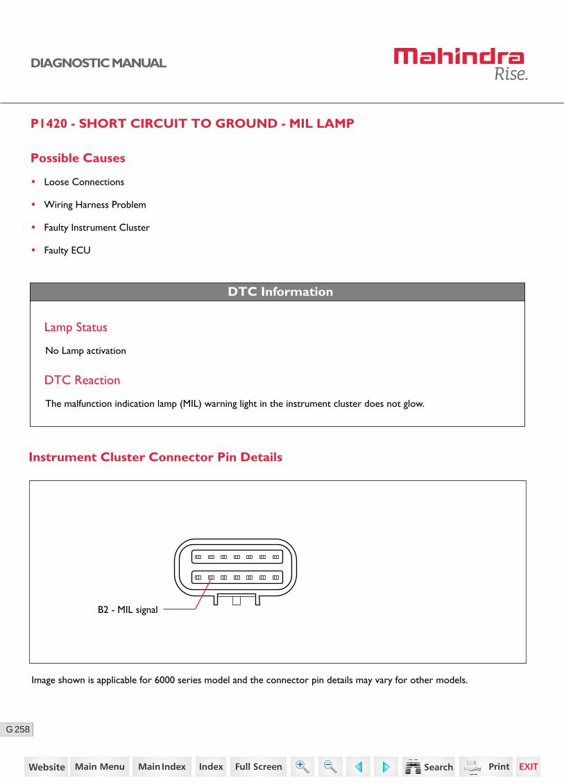
258G
DIAGNOSTIC MANUAL
P1420 - SHORT CIRCUIT TO GROUND - MIL LAMP
DTC Information
Lamp Status
No Lamp activation
DTC Reaction
The malfunction indication lamp (MIL) warning light in the instrument cluster does not glow.
B2 - MIL signal
Instrument Cluster Connector Pin Details
Possible Causes
• Loose Connections
• Wiring Harness Problem
• Faulty Instrument Cluster
• Faulty ECU
Image shown is applicable for 6000 series model and the connector pin details may vary for other models.
186https://www.truck-manuals.net/
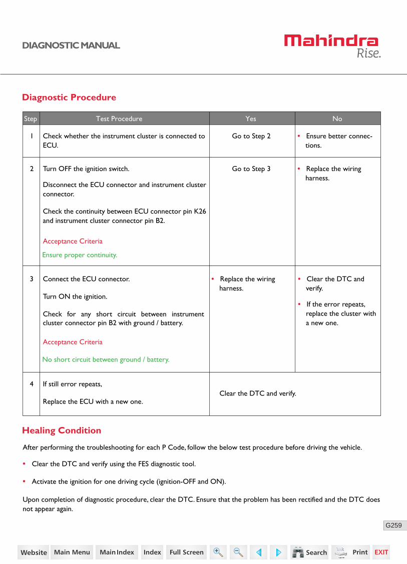
259G
DIAGNOSTIC MANUAL
3 Connect the ECU connector.
Turn ON the ignition.
Check for any short circuit between instrument cluster connector pin B2 with ground / battery.
• Replace the wiring harness.
No
Diagnostic Procedure
2 Turn OFF the ignition switch.
Disconnect the ECU connector and instrument cluster connector.
Check the continuity between ECU connector pin K26 and instrument cluster connector pin B2.
• Replace the wiring harness.
1 Check whether the instrument cluster is connected to ECU.
Go to Step 2 • Ensure better connec-tions.
Acceptance Criteria
Ensure proper continuity.
Step Test Procedure Yes No
Go to Step 3
Acceptance Criteria
No short circuit between ground / battery.
4
• Clear the DTC and verify.
• If the error repeats, replace the cluster with a new one.
If still error repeats,
Replace the ECU with a new one.Clear the DTC and verify.
• Clear the DTC and verify using the FES diagnostic tool.
• Activate the ignition for one driving cycle (ignition-OFF and ON).
Healing Condition
After performing the troubleshooting for each P Code, follow the below test procedure before driving the vehicle.
Upon completion of diagnostic procedure, clear the DTC. Ensure that the problem has been rectified and the DTC does not appear again.
187https://www.truck-manuals.net/
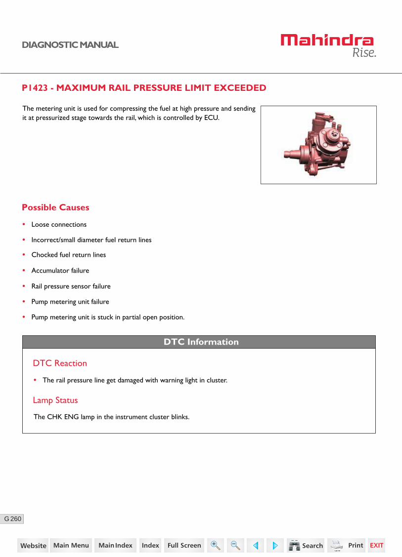
260G
DIAGNOSTIC MANUAL
P1423 - MAXIMUM RAIL PRESSURE LIMIT EXCEEDED
The metering unit is used for compressing the fuel at high pressure and sending it at pressurized stage towards the rail, which is controlled by ECU.
Possible Causes
• Loose connections
• Incorrect/small diameter fuel return lines
• Chocked fuel return lines
• Accumulator failure
• Rail pressure sensor failure
• Pump metering unit failure
• Pump metering unit is stuck in partial open position.
DTC Information
DTC Reaction
• The rail pressure line get damaged with warning light in cluster.
Lamp Status
The CHK ENG lamp in the instrument cluster blinks.
188https://www.truck-manuals.net/
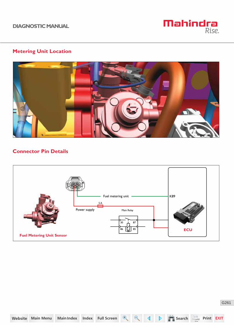
261G
DIAGNOSTIC MANUAL
Metering Unit Location
Connector Pin Details
Fuel Metering Unit SensorECU
K89Fuel metering unit
Power supply
30
5 A
86 85
87
Main Relay
189https://www.truck-manuals.net/
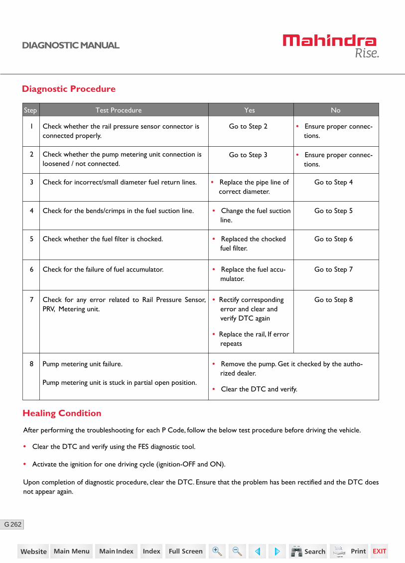
262G
DIAGNOSTIC MANUAL
Diagnostic Procedure
1 Check whether the rail pressure sensor connector isconnected properly.
Go to Step 2 • Ensure proper connec-tions.
Go to Step 3 • Ensure proper connec-tions.
2 Check whether the pump metering unit connection is loosened / not connected.
3 Check for incorrect/small diameter fuel return lines. Go to Step 4• Replace the pipe line of correct diameter.
4 Check for the bends/crimps in the fuel suction line. Go to Step 5• Change the fuel suction line.
5 Check whether the fuel filter is chocked. Go to Step 6• Replaced the chocked fuel filter.
8 Pump metering unit failure.
Pump metering unit is stuck in partial open position.
• Remove the pump. Get it checked by the autho-rized dealer.
• Clear the DTC and verify.
Step Test Procedure Yes No
• Clear the DTC and verify using the FES diagnostic tool.
• Activate the ignition for one driving cycle (ignition-OFF and ON).
Healing Condition
After performing the troubleshooting for each P Code, follow the below test procedure before driving the vehicle.
Upon completion of diagnostic procedure, clear the DTC. Ensure that the problem has been rectified and the DTC does not appear again.
6 Check for the failure of fuel accumulator. Go to Step 7• Replace the fuel accu-mulator.
7 Go to Step 8Check for any error related to Rail Pressure Sensor, PRV, Metering unit.
• Rectify corresponding error and clear and verify DTC again
• Replace the rail, If error repeats
190https://www.truck-manuals.net/
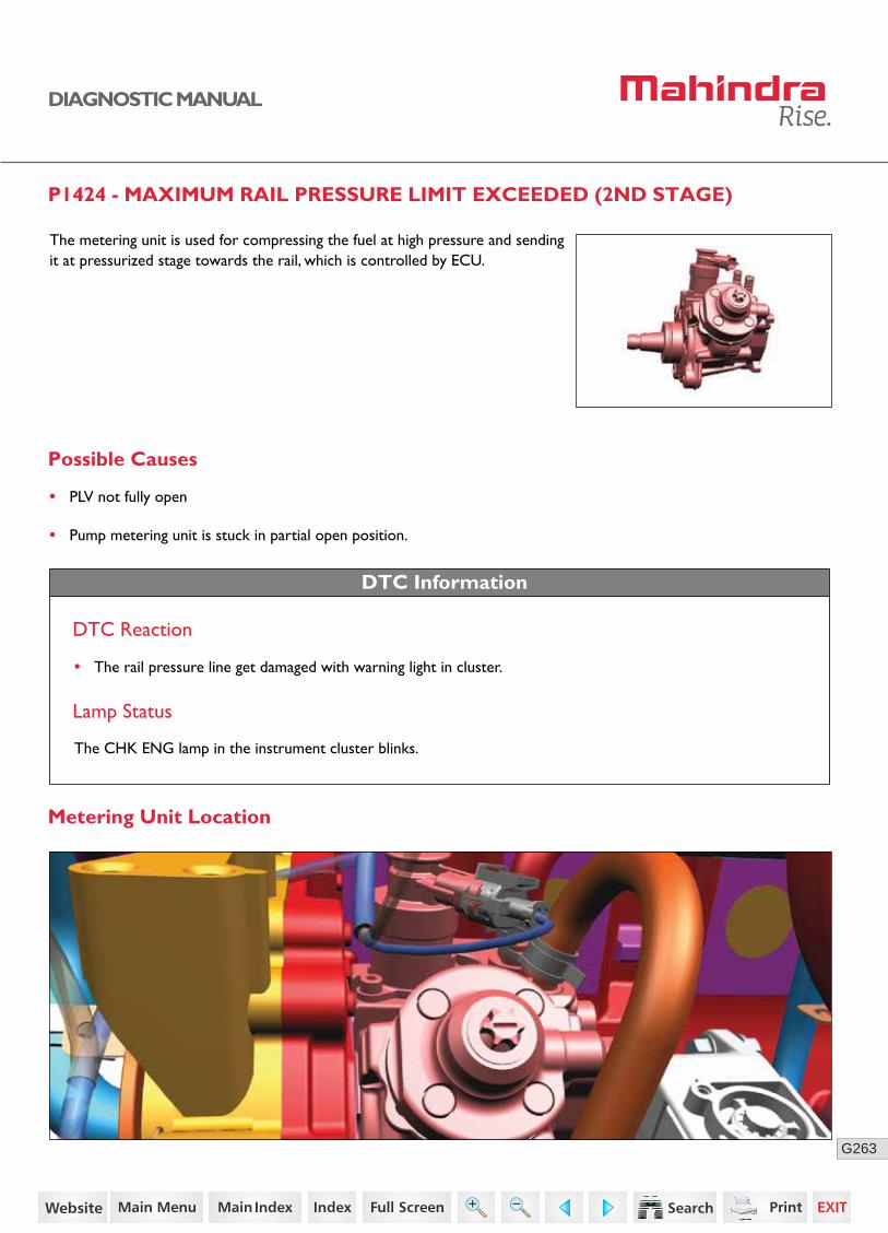
263G
DIAGNOSTIC MANUAL
P1424 - MAXIMUM RAIL PRESSURE LIMIT EXCEEDED (2ND STAGE)
The metering unit is used for compressing the fuel at high pressure and sending it at pressurized stage towards the rail, which is controlled by ECU.
Possible Causes
• PLV not fully open
• Pump metering unit is stuck in partial open position.
DTC Information
DTC Reaction
• The rail pressure line get damaged with warning light in cluster.
Lamp Status
The CHK ENG lamp in the instrument cluster blinks.
Metering Unit Location
191https://www.truck-manuals.net/
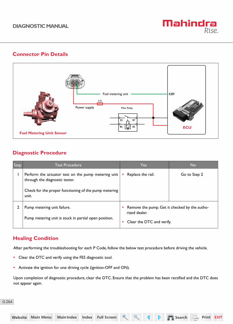
264G
DIAGNOSTIC MANUAL
Connector Pin Details
Diagnostic Procedure
2 Pump metering unit failure.
Pump metering unit is stuck in partial open position.
• Remove the pump. Get it checked by the autho-rized dealer.
• Clear the DTC and verify.
Step Test Procedure Yes No
• Clear the DTC and verify using the FES diagnostic tool.
• Activate the ignition for one driving cycle (ignition-OFF and ON).
Healing Condition
After performing the troubleshooting for each P Code, follow the below test procedure before driving the vehicle.
Upon completion of diagnostic procedure, clear the DTC. Ensure that the problem has been rectified and the DTC does not appear again.
1 Perform the actuator test on the pump metering unit through the diagnostic tester.
Check for the proper functioning of the pump metering unit.
Go to Step 2• Replace the rail.
Fuel Metering Unit SensorECU
K89Fuel metering unit
Power supply
30
5 A
86 85
87
Main Relay
192https://www.truck-manuals.net/
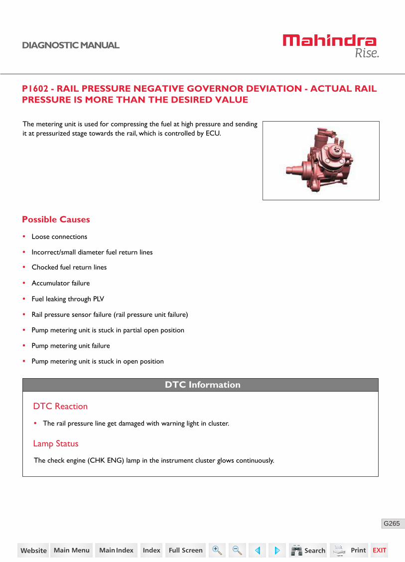
265G
DIAGNOSTIC MANUAL
P1602 - RAIL PRESSURE NEGATIVE GOVERNOR DEVIATION - ACTUAL RAIL PRESSURE IS MORE THAN THE DESIRED VALUE
The metering unit is used for compressing the fuel at high pressure and sending it at pressurized stage towards the rail, which is controlled by ECU.
Possible Causes
• Loose connections
• Incorrect/small diameter fuel return lines
• Chocked fuel return lines
• Accumulator failure
• Fuel leaking through PLV
• Rail pressure sensor failure (rail pressure unit failure)
• Pump metering unit is stuck in partial open position
• Pump metering unit failure
• Pump metering unit is stuck in open position
DTC Information
DTC Reaction
• The rail pressure line get damaged with warning light in cluster.
Lamp Status
The check engine (CHK ENG) lamp in the instrument cluster glows continuously.
193https://www.truck-manuals.net/
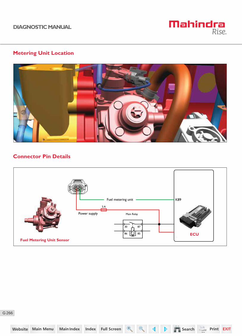
266G
DIAGNOSTIC MANUAL
Metering Unit Location
Connector Pin Details
Fuel Metering Unit SensorECU
K89Fuel metering unit
Power supply
30
5 A
86 85
87
Main Relay
194https://www.truck-manuals.net/
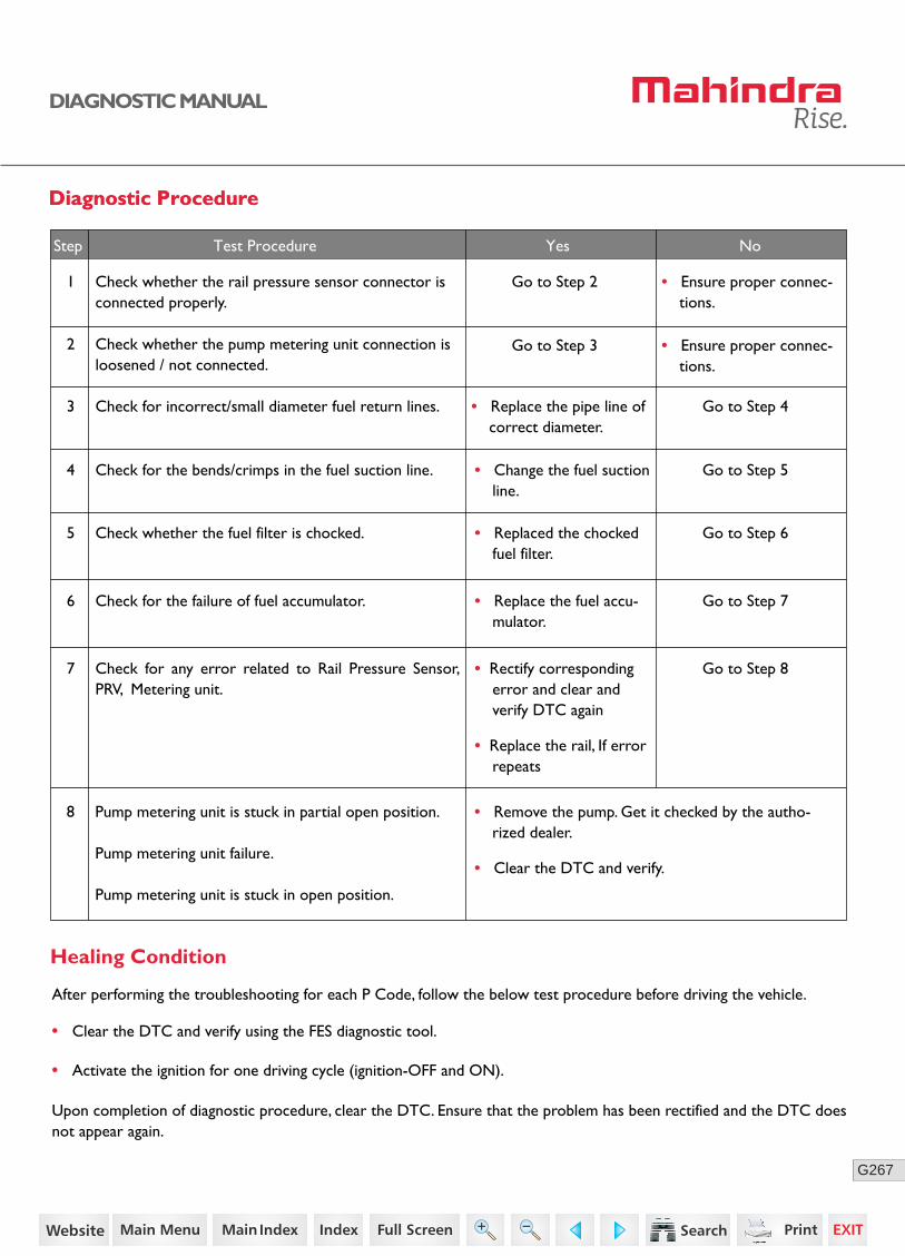
267G
DIAGNOSTIC MANUAL
Diagnostic ProcedureDiagnostic Procedure
1 Check whether the rail pressure sensor connector isconnected properly.
Go to Step 2 • Ensure proper connec-tions.
Go to Step 3 • Ensure proper connec-tions.
2 Check whether the pump metering unit connection is loosened / not connected.
3 Check for incorrect/small diameter fuel return lines. Go to Step 4• Replace the pipe line of correct diameter.
4 Check for the bends/crimps in the fuel suction line. Go to Step 5• Change the fuel suction line.
5 Check whether the fuel filter is chocked. Go to Step 6• Replaced the chocked fuel filter.
8 Pump metering unit is stuck in partial open position.
Pump metering unit failure.
Pump metering unit is stuck in open position.
• Remove the pump. Get it checked by the autho-rized dealer.
• Clear the DTC and verify.
Step Test Procedure Yes No
• Clear the DTC and verify using the FES diagnostic tool.
• Activate the ignition for one driving cycle (ignition-OFF and ON).
Healing Condition
After performing the troubleshooting for each P Code, follow the below test procedure before driving the vehicle.
Upon completion of diagnostic procedure, clear the DTC. Ensure that the problem has been rectified and the DTC does not appear again.
6 Check for the failure of fuel accumulator. Go to Step 7• Replace the fuel accu-mulator.
7 Go to Step 8Check for any error related to Rail Pressure Sensor, PRV, Metering unit.
• Rectify corresponding error and clear and verify DTC again
• Replace the rail, If error repeats
195https://www.truck-manuals.net/
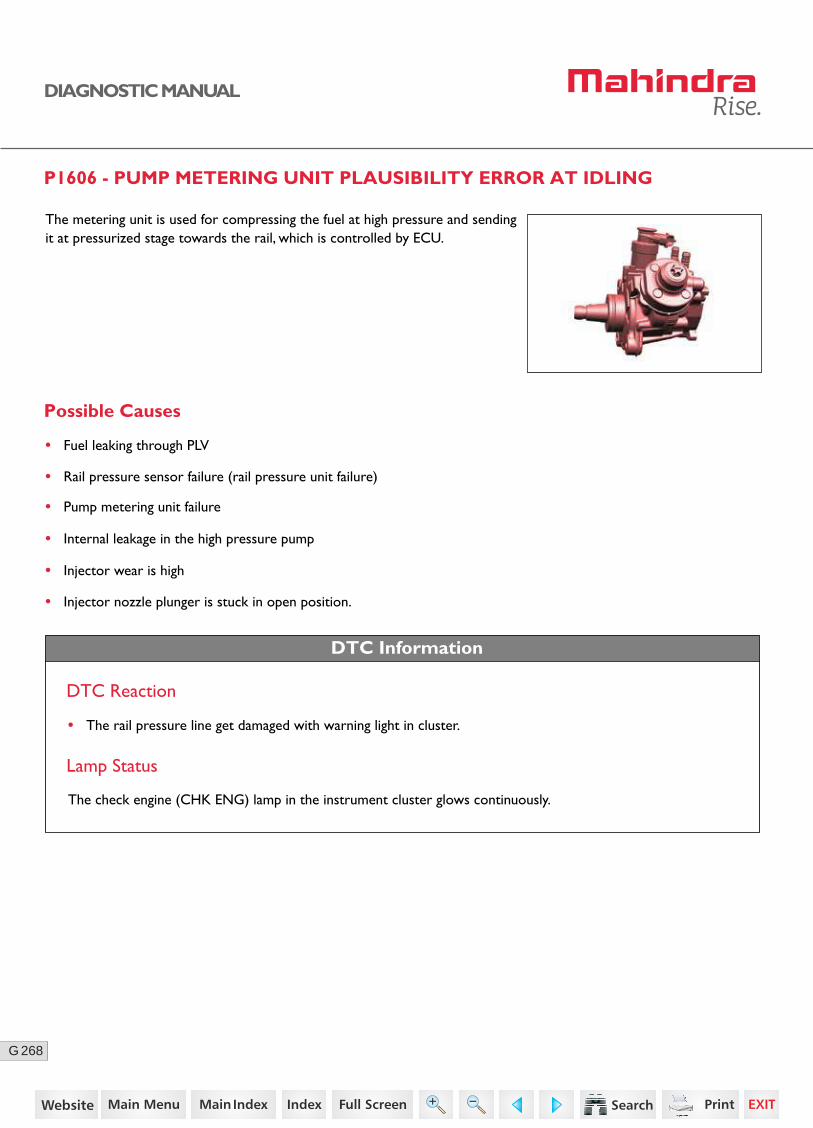
268G
DIAGNOSTIC MANUAL
P1606 - PUMP METERING UNIT PLAUSIBILITY ERROR AT IDLING
The metering unit is used for compressing the fuel at high pressure and sending it at pressurized stage towards the rail, which is controlled by ECU.
Possible Causes
• Fuel leaking through PLV
• Rail pressure sensor failure (rail pressure unit failure)
• Pump metering unit failure
• Internal leakage in the high pressure pump
• Injector wear is high
• Injector nozzle plunger is stuck in open position.
DTC Information
DTC Reaction
• The rail pressure line get damaged with warning light in cluster.
Lamp Status
The check engine (CHK ENG) lamp in the instrument cluster glows continuously.
196https://www.truck-manuals.net/

269G
DIAGNOSTIC MANUAL
Metering Unit Location
Connector Pin Details
Fuel Metering Unit SensorECU
K89Fuel metering unit
Power supply
30
5 A
86 85
87
Main Relay
197https://www.truck-manuals.net/
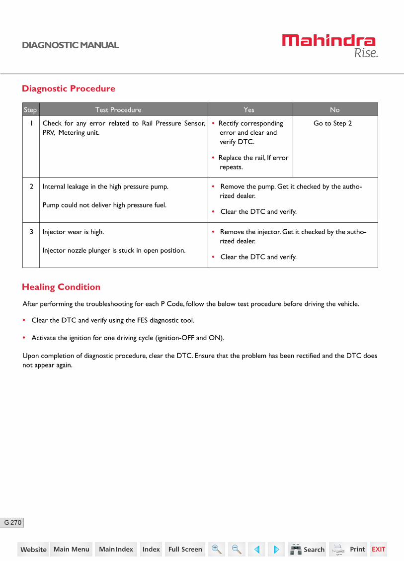
270G
DIAGNOSTIC MANUAL
Diagnostic Procedure
1 Go to Step 2
2 Internal leakage in the high pressure pump.
Pump could not deliver high pressure fuel.
3 Injector wear is high.
Injector nozzle plunger is stuck in open position.
• Remove the pump. Get it checked by the autho-rized dealer.
• Clear the DTC and verify.
• Remove the injector. Get it checked by the autho-rized dealer.
• Clear the DTC and verify.
Step Test Procedure Yes No
• Clear the DTC and verify using the FES diagnostic tool.
• Activate the ignition for one driving cycle (ignition-OFF and ON).
Healing Condition
After performing the troubleshooting for each P Code, follow the below test procedure before driving the vehicle.
Upon completion of diagnostic procedure, clear the DTC. Ensure that the problem has been rectified and the DTC does not appear again.
Check for any error related to Rail Pressure Sensor, PRV, Metering unit.
• Rectify corresponding error and clear and verify DTC.
• Replace the rail, If error repeats.
198https://www.truck-manuals.net/
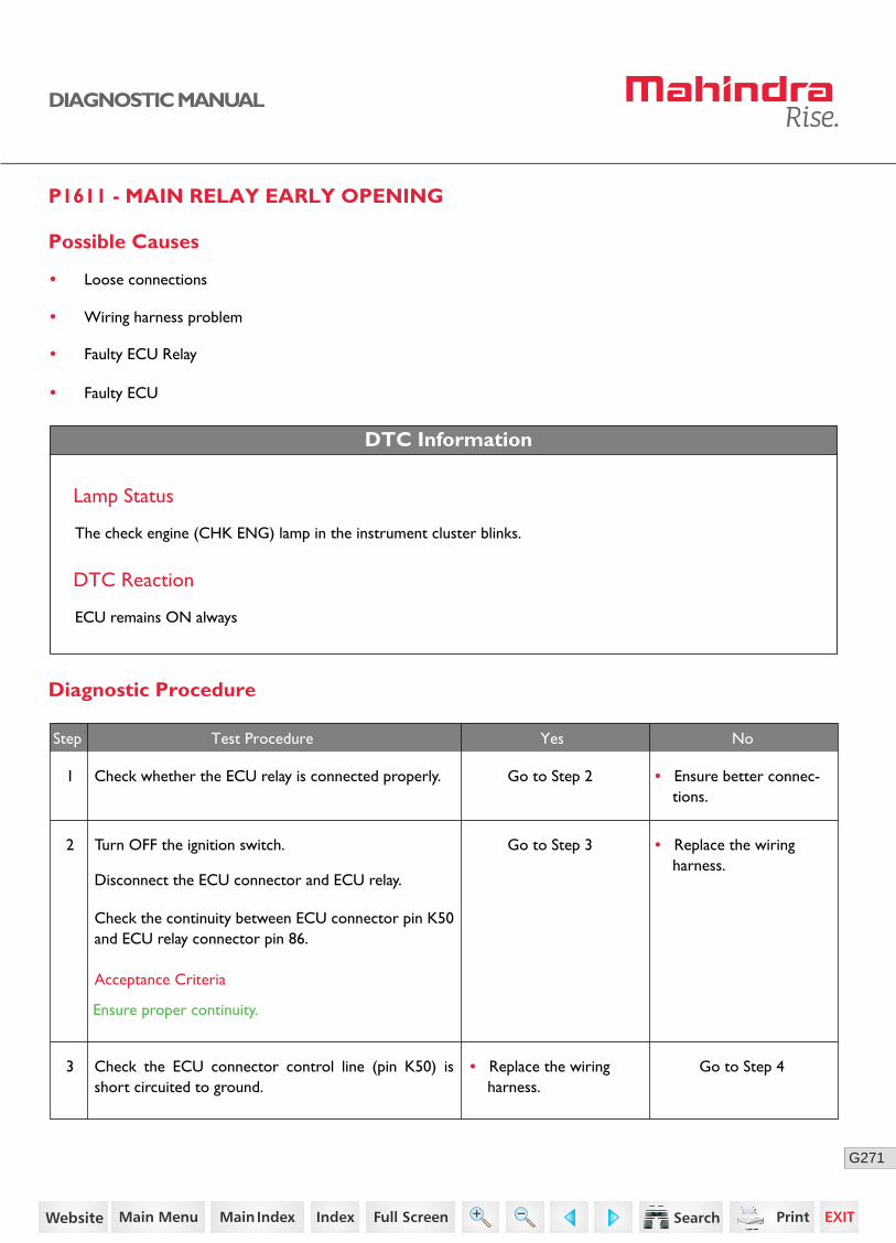
271G
DIAGNOSTIC MANUAL
P1611 - MAIN RELAY EARLY OPENING
Possible Causes
• Loose connections
• Wiring harness problem
• Faulty ECU Relay
• Faulty ECU
DTC Information
Lamp Status
The check engine (CHK ENG) lamp in the instrument cluster blinks.
DTC Reaction
ECU remains ON always
Diagnostic Procedure
2 Turn OFF the ignition switch.
Disconnect the ECU connector and ECU relay.
Check the continuity between ECU connector pin K50 and ECU relay connector pin 86.
Go to Step 3 • Replace the wiring harness.
3 Check the ECU connector control line (pin K50) is short circuited to ground.
Go to Step 4• Replace the wiring harness.
Acceptance Criteria
Ensure proper continuity.
Step Test Procedure Yes No
1 Check whether the ECU relay is connected properly. Go to Step 2 • Ensure better connec-tions.
199https://www.truck-manuals.net/
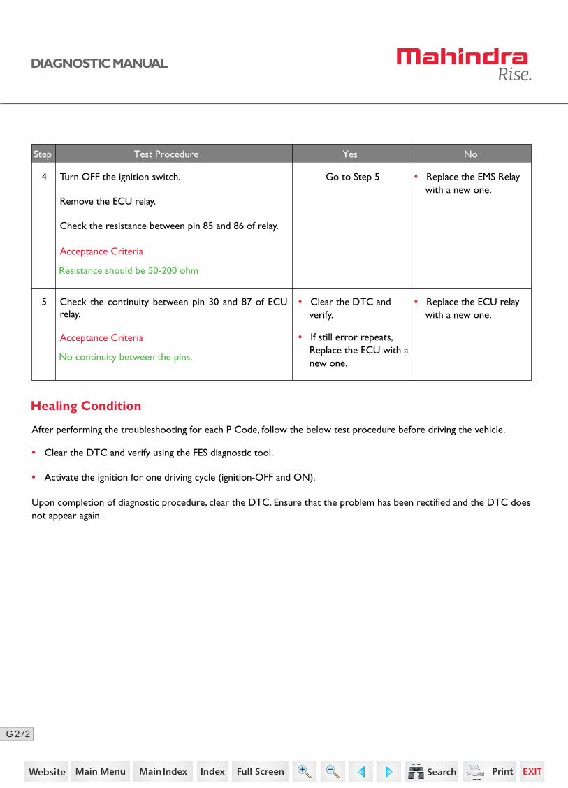
272G
DIAGNOSTIC MANUAL
4 Turn OFF the ignition switch.
Remove the ECU relay.
Check the resistance between pin 85 and 86 of relay.
Go to Step 5 • Replace the EMS Relay with a new one.
5 Check the continuity between pin 30 and 87 of ECU relay.
• Clear the DTC and verify.
• If still error repeats, Replace the ECU with a new one.
• Replace the ECU relay with a new one.
Step Test Procedure Yes No
• Clear the DTC and verify using the FES diagnostic tool.
• Activate the ignition for one driving cycle (ignition-OFF and ON).
Healing Condition
After performing the troubleshooting for each P Code, follow the below test procedure before driving the vehicle.
Upon completion of diagnostic procedure, clear the DTC. Ensure that the problem has been rectified and the DTC does not appear again.
Acceptance Criteria
Resistance should be 50-200 ohm
Acceptance Criteria
No continuity between the pins.
200https://www.truck-manuals.net/
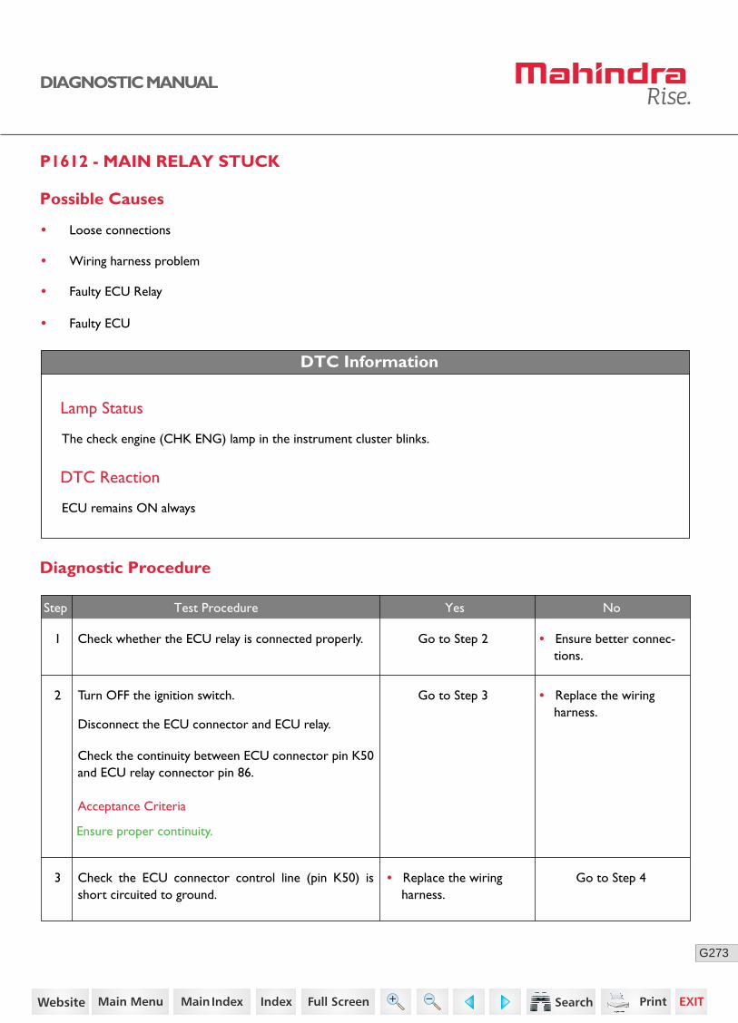
273G
DIAGNOSTIC MANUAL
P1612 - MAIN RELAY STUCK
Possible Causes
• Loose connections
• Wiring harness problem
• Faulty ECU Relay
• Faulty ECU
DTC Information
Lamp Status
The check engine (CHK ENG) lamp in the instrument cluster blinks.
DTC Reaction
ECU remains ON always
Diagnostic Procedure
2 Turn OFF the ignition switch.
Disconnect the ECU connector and ECU relay.
Check the continuity between ECU connector pin K50 and ECU relay connector pin 86.
Go to Step 3 • Replace the wiring harness.
3 Check the ECU connector control line (pin K50) is short circuited to ground.
Go to Step 4• Replace the wiring harness.
Acceptance Criteria
Ensure proper continuity.
Step Test Procedure Yes No
1 Check whether the ECU relay is connected properly. Go to Step 2 • Ensure better connec-tions.
201https://www.truck-manuals.net/

274G
DIAGNOSTIC MANUAL
4 Turn OFF the ignition switch.
Remove the ECU relay.
Check the resistance between pin 85 and 86 of relay.
Go to Step 5 • Replace the EMS Relay with a new one.
5 Check the continuity between pin 30 and 87 of ECU relay.
• Clear the DTC and verify.
• If still error repeats, Replace the ECU with a new one.
• Replace the ECU relay with a new one.
Step Test Procedure Yes No
• Clear the DTC and verify using the FES diagnostic tool.
• Activate the ignition for one driving cycle (ignition-OFF and ON).
Healing Condition
After performing the troubleshooting for each P Code, follow the below test procedure before driving the vehicle.
Upon completion of diagnostic procedure, clear the DTC. Ensure that the problem has been rectified and the DTC does not appear again.
Acceptance Criteria
Resistance should be 50-200 ohm
Acceptance Criteria
No continuity between the pins.
202https://www.truck-manuals.net/
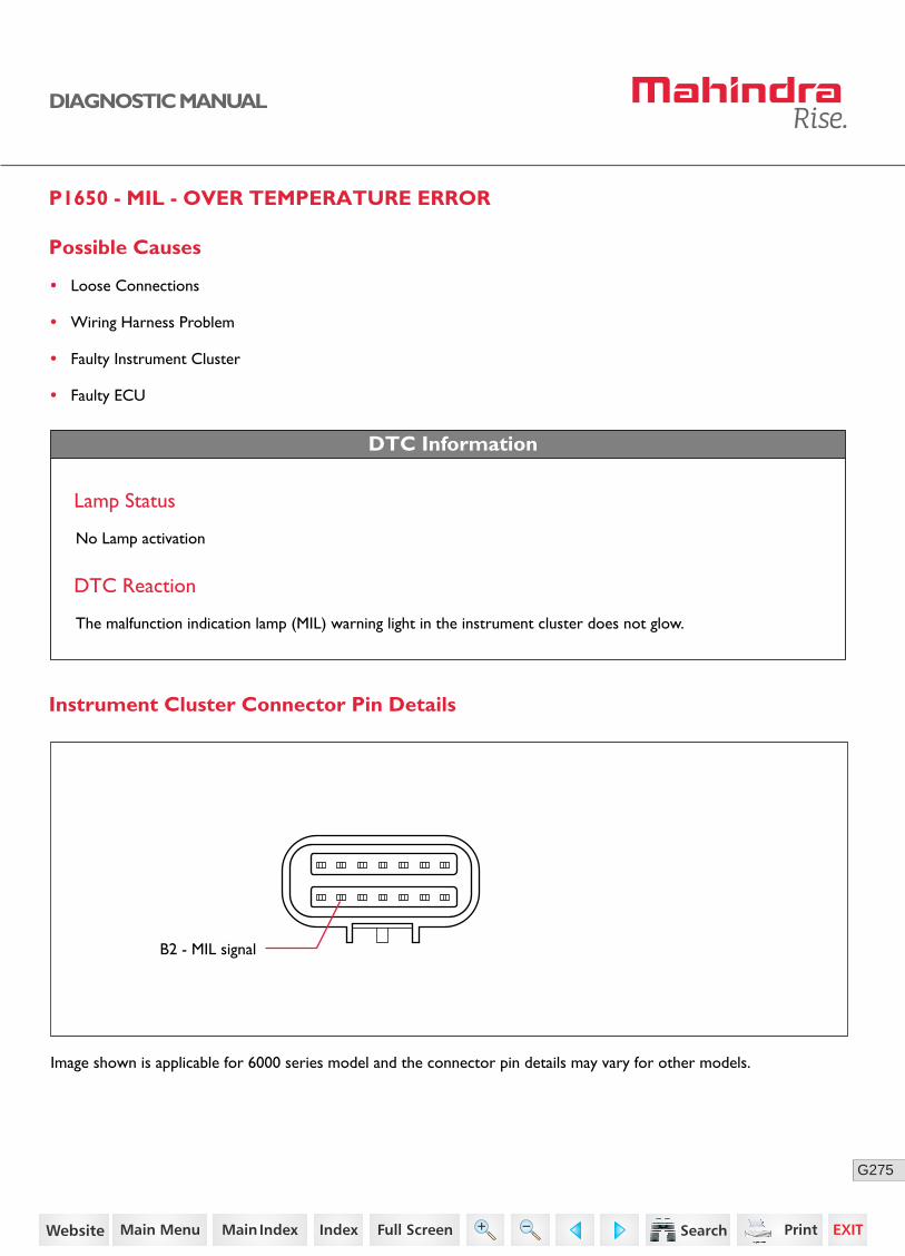
275G
DIAGNOSTIC MANUAL
P1650 - MIL - OVER TEMPERATURE ERROR
DTC Information
Lamp Status
No Lamp activation
DTC Reaction
The malfunction indication lamp (MIL) warning light in the instrument cluster does not glow.
Possible Causes
• Loose Connections
• Wiring Harness Problem
• Faulty Instrument Cluster
• Faulty ECU
B2 - MIL signal
Instrument Cluster Connector Pin Details
Image shown is applicable for 6000 series model and the connector pin details may vary for other models.
203https://www.truck-manuals.net/

276G
DIAGNOSTIC MANUAL
3 Connect the ECU connector.
Turn ON the ignition.
Check for any short circuit between instrument cluster connector pin B2 with ground / battery.
• Replace the wiring harness.
No
Diagnostic Procedure
2 Turn OFF the ignition switch.
Disconnect the ECU connector and instrument cluster connector.
Check the continuity between ECU connector pin K26 and instrument cluster connector pin B2.
• Replace the wiring harness.
1 Check whether the instrument cluster is connected to ECU.
Go to Step 2 • Ensure better connec-tions.
Acceptance Criteria
Ensure proper continuity.
Step Test Procedure Yes No
Go to Step 3
Acceptance Criteria
No short circuit between ground / battery.
4
• Clear the DTC and verify.
• If the error repeats, replace the cluster with a new one.
If still error repeats,
Replace the ECU with a new one.Clear the DTC and verify.
• Clear the DTC and verify using the FES diagnostic tool.
• Activate the ignition for one driving cycle (ignition-OFF and ON).
Healing Condition
After performing the troubleshooting for each P Code, follow the below test procedure before driving the vehicle.
Upon completion of diagnostic procedure, clear the DTC. Ensure that the problem has been rectified and the DTC does not appear again.
204https://www.truck-manuals.net/
277G
DIAGNOSTIC MANUAL
P1701 - SPI/COM - ERRORS OF THE CY320
Possible Causes
• Communication errors in CY 320 chip
DTC Information
Lamp Status
No Lamp activation
Vehicle Behaviour
The engine will not start.
Diagnostic Procedure
1. Clear the error through the diagnostic tester.
2. If the problem persists, replace the ECU.
• Clear the DTC and verify using the FES diagnostic tool.
• Activate the ignition for one driving cycle (ignition-OFF and ON).
Healing Condition
After performing the troubleshooting for each P Code, follow the below test procedure before driving the vehicle.
Upon completion of diagnostic procedure, clear the DTC. Ensure that the problem has been rectified and the DTC does not appear again.
205https://www.truck-manuals.net/
278G
DIAGNOSTIC MANUAL
P1702 - EEP ERASE ERROR BASED ON THE ERROR FOR MORE BLOCKS
Possible Causes
• ECU internal error - Electrically erasable programmable read-only memory (EEPROM) erase is not possible.
DTC Information
Lamp Status
No Lamp activation
Vehicle Behaviour
The engine will not start.
Diagnostic Procedure
1. Switch ON and OFF the ignition key for 1 or 2 times.
2. If the problem persists, replace the ECU.
• Clear the DTC and verify using the FES diagnostic tool.
• Activate the ignition for one driving cycle (ignition-OFF and ON).
Healing Condition
After performing the troubleshooting for each P Code, follow the below test procedure before driving the vehicle.
Upon completion of diagnostic procedure, clear the DTC. Ensure that the problem has been rectified and the DTC does not appear again.
206https://www.truck-manuals.net/
279G
DIAGNOSTIC MANUAL
P1703 - EEP READ ERROR BASED ON THE ERROR FOR MORE BLOCKS
Possible Causes
• ECU internal error - EEPROM read is not possible.
DTC Information
Lamp Status
No Lamp activation
Vehicle Behaviour
The engine will not start.
Diagnostic Procedure
1. Switch ON and OFF the ignition key for 1 or 2 times.
2. If the problem persists, replace the ECU.
• Clear the DTC and verify using the FES diagnostic tool.
• Activate the ignition for one driving cycle (ignition-OFF and ON).
Healing Condition
After performing the troubleshooting for each P Code, follow the below test procedure before driving the vehicle.
Upon completion of diagnostic procedure, clear the DTC. Ensure that the problem has been rectified and the DTC does not appear again.
207https://www.truck-manuals.net/
280G
DIAGNOSTIC MANUAL
P1704 - EEP WRITE ERROR BASED ON THE ERROR FOR ONE BLOCK
Possible Causes
• ECU internal error - EEPROM write is not possible.
DTC Information
Lamp Status
No Lamp activation
Vehicle Behaviour
The engine will not start.
Diagnostic Procedure
1. Switch ON and OFF the ignition key for 1 or 2 times.
2. If the problem persists, replace the ECU.
• Clear the DTC and verify using the FES diagnostic tool.
• Activate the ignition for one driving cycle (ignition-OFF and ON).
Healing Condition
After performing the troubleshooting for each P Code, follow the below test procedure before driving the vehicle.
Upon completion of diagnostic procedure, clear the DTC. Ensure that the problem has been rectified and the DTC does not appear again.
208https://www.truck-manuals.net/
281G
DIAGNOSTIC MANUAL
P1705 - ERROR CHECK OF NO-LOAD TEST PULSE OPERATION
Possible Causes
• Error detected in the plausibility check of the ADC by no load test pulse test. The ECU has an internal error.
DTC Information
Lamp Status
No Lamp activation
Vehicle Behaviour
The engine will not start.
Diagnostic Procedure
1. Clear the error through the diagnostic tester.
2. If the problem persists, replace the ECU.
• Clear the DTC and verify using the FES diagnostic tool.
• Activate the ignition for one driving cycle (ignition-OFF and ON).
Healing Condition
After performing the troubleshooting for each P Code, follow the below test procedure before driving the vehicle.
Upon completion of diagnostic procedure, clear the DTC. Ensure that the problem has been rectified and the DTC does not appear again.
209https://www.truck-manuals.net/
282G
DIAGNOSTIC MANUAL
P1706 - ERROR IN THE PLAUSIBILITY OF THE TEST VOLTAGE
Possible Causes
• Error detected in the plausibility check of the ADC by voltage test signal. The ECU has an internal error.
DTC Information
Lamp Status
No Lamp activation
Vehicle Behaviour
The engine will not start.
Diagnostic Procedure
1. Clear the error through the diagnostic tester.
2. If the problem persists, replace the ECU.
• Clear the DTC and verify using the FES diagnostic tool.
• Activate the ignition for one driving cycle (ignition-OFF and ON).
Healing Condition
After performing the troubleshooting for each P Code, follow the below test procedure before driving the vehicle.
Upon completion of diagnostic procedure, clear the DTC. Ensure that the problem has been rectified and the DTC does not appear again.
210https://www.truck-manuals.net/
283G
DIAGNOSTIC MANUAL
P1707 - CHECK OF THE RATIO METRIC CORRECTION
Possible Causes
• Error detected in the plausibility check of the ADC in the voltage ratio. The ECU has an internal error.
DTC Information
Lamp Status
No Lamp activation
Vehicle Behaviour
The engine will not start.
Diagnostic Procedure
1. Clear the error through the diagnostic tester.
2. If the problem persists, replace the ECU.
• Clear the DTC and verify using the FES diagnostic tool.
• Activate the ignition for one driving cycle (ignition-OFF and ON).
Healing Condition
After performing the troubleshooting for each P Code, follow the below test procedure before driving the vehicle.
Upon completion of diagnostic procedure, clear the DTC. Ensure that the problem has been rectified and the DTC does not appear again.
211https://www.truck-manuals.net/
284G
DIAGNOSTIC MANUAL
P1708 - ERROR IN THE PLAUSIBILITY OF FC AND MM
Possible Causes
• Error in the plausibility of FC and MM communication. The ECU has an internal error.
DTC Information
Lamp Status
No Lamp activation
Vehicle Behaviour
The engine will not start.
Diagnostic Procedure
1. Clear the error through the diagnostic tester.
2. If the problem persists, replace the ECU.
• Clear the DTC and verify using the FES diagnostic tool.
• Activate the ignition for one driving cycle (ignition-OFF and ON).
Healing Condition
After performing the troubleshooting for each P Code, follow the below test procedure before driving the vehicle.
Upon completion of diagnostic procedure, clear the DTC. Ensure that the problem has been rectified and the DTC does not appear again.
212https://www.truck-manuals.net/
285G
DIAGNOSTIC MANUAL
P1709 - ERROR REPORT DUE TO AN INTERRUPTED SPI COMMUNICATION
Possible Causes
• Multiple error in complete ROM-test during post drive detected. The ECU has an internal error.
DTC Information
Lamp Status
No Lamp activation
Vehicle Behaviour
The engine will not start.
Diagnostic Procedure
1. Clear the error through the diagnostic tester.
2. If the problem persists, replace the ECU.
• Clear the DTC and verify using the FES diagnostic tool.
• Activate the ignition for one driving cycle (ignition-OFF and ON).
Healing Condition
After performing the troubleshooting for each P Code, follow the below test procedure before driving the vehicle.
Upon completion of diagnostic procedure, clear the DTC. Ensure that the problem has been rectified and the DTC does not appear again.
213https://www.truck-manuals.net/
286G
DIAGNOSTIC MANUAL
P1710 - MULTIPLE ERROR IN COMPLETE ROM TEST DURING POST DRIVE DETECTED
Possible Causes
• Multiple error in complete ROM-test during post drive detected. The ECU has an internal error.
DTC Information
Lamp Status
No Lamp activation
Vehicle Behaviour
The engine will not start.
Diagnostic Procedure
1. Clear the error through the diagnostic tester.
2. If the problem persists, replace the ECU.
• Clear the DTC and verify using the FES diagnostic tool.
• Activate the ignition for one driving cycle (ignition-OFF and ON).
Healing Condition
After performing the troubleshooting for each P Code, follow the below test procedure before driving the vehicle.
Upon completion of diagnostic procedure, clear the DTC. Ensure that the problem has been rectified and the DTC does not appear again.
214https://www.truck-manuals.net/
287G
DIAGNOSTIC MANUAL
P1711 - TOO LESS BYTES RECEIVED BY MM FROM CPU AS RESPONSE
Possible Causes
• Too less bytes received by MM from CPU as response. The ECU has an internal error.
DTC Information
Lamp Status
No Lamp activation
Vehicle Behaviour
The engine will not start.
Diagnostic Procedure
1. Clear the error through the diagnostic tester.
2. If the problem persists, replace the ECU.
• Clear the DTC and verify using the FES diagnostic tool.
• Activate the ignition for one driving cycle (ignition-OFF and ON).
Healing Condition
After performing the troubleshooting for each P Code, follow the below test procedure before driving the vehicle.
Upon completion of diagnostic procedure, clear the DTC. Ensure that the problem has been rectified and the DTC does not appear again.
215https://www.truck-manuals.net/
288G
DIAGNOSTIC MANUAL
P1712 - DFC TO SET A TORQUE LIMITATION ONCE AN ERROR IS DETECTED BEFORE MOCSOP'S ERROR REACTION
Possible Causes
• Error during SOP test (defective injector or shut-off path). The ECU has an internal error.
DTC Information
Lamp Status
No Lamp activation
Vehicle Behaviour
The engine will not start.
Diagnostic Procedure
1. Clear the error through the diagnostic tester.
2. If the problem persists, replace the ECU.
• Clear the DTC and verify using the FES diagnostic tool.
• Activate the ignition for one driving cycle (ignition-OFF and ON).
Healing Condition
After performing the troubleshooting for each P Code, follow the below test procedure before driving the vehicle.
Upon completion of diagnostic procedure, clear the DTC. Ensure that the problem has been rectified and the DTC does not appear again.
216https://www.truck-manuals.net/
289G
DIAGNOSTIC MANUAL
P1713 - ERROR TRYING TO SET MM RESPONSE TIME
Possible Causes
• Error trying to set MM response time. The ECU has an internal error.
DTC Information
Lamp Status
No Lamp activation
Vehicle Behaviour
The engine will not start.
Diagnostic Procedure
1. Clear the error through the diagnostic tester.
2. If the problem persists, replace the ECU.
• Clear the DTC and verify using the FES diagnostic tool.
• Activate the ignition for one driving cycle (ignition-OFF and ON).
Healing Condition
After performing the troubleshooting for each P Code, follow the below test procedure before driving the vehicle.
Upon completion of diagnostic procedure, clear the DTC. Ensure that the problem has been rectified and the DTC does not appear again.
217https://www.truck-manuals.net/

290G
DIAGNOSTIC MANUAL
P1714 - ERROR DETECTED IN THE SPI COMMUNICATION
Possible Causes
• Error detected in the SPI communication. The ECU has an internal error.
DTC Information
Lamp Status
No Lamp activation
Vehicle Behaviour
The engine will not start.
Diagnostic Procedure
1. Clear the error through the diagnostic tester.
2. If the problem persists, replace the ECU.
• Clear the DTC and verify using the FES diagnostic tool.
• Activate the ignition for one driving cycle (ignition-OFF and ON).
Healing Condition
After performing the troubleshooting for each P Code, follow the below test procedure before driving the vehicle.
Upon completion of diagnostic procedure, clear the DTC. Ensure that the problem has been rectified and the DTC does not appear again.
218https://www.truck-manuals.net/
291G
DIAGNOSTIC MANUAL
P1715 - SHUT-OFF PATH TEST OF THE UNDER VOLTAGE DETECTION
Possible Causes
• Error in the check of the shut-off path test of the under voltage detection. The ECU has an internal error.
DTC Information
Lamp Status
No Lamp activation
Vehicle Behaviour
The engine will not start.
Diagnostic Procedure
1. Clear the error through the diagnostic tester.
2. If the problem persists, replace the ECU.
• Clear the DTC and verify using the FES diagnostic tool.
• Activate the ignition for one driving cycle (ignition-OFF and ON).
Healing Condition
After performing the troubleshooting for each P Code, follow the below test procedure before driving the vehicle.
Upon completion of diagnostic procedure, clear the DTC. Ensure that the problem has been rectified and the DTC does not appear again.
219https://www.truck-manuals.net/
292G
DIAGNOSTIC MANUAL
P1716 - SHUT-OFF PATH OF THE MONITORING MODULE
Possible Causes
• Error in the check of the shut-off path of the monitoring module.
DTC Information
Lamp Status
No Lamp activation
Vehicle Behaviour
The engine will not start.
Diagnostic Procedure
1. Clear the error through the diagnostic tester.
2. If the problem persists, replace the ECU.
• Clear the DTC and verify using the FES diagnostic tool.
• Activate the ignition for one driving cycle (ignition-OFF and ON).
Healing Condition
After performing the troubleshooting for each P Code, follow the below test procedure before driving the vehicle.
Upon completion of diagnostic procedure, clear the DTC. Ensure that the problem has been rectified and the DTC does not appear again.
220https://www.truck-manuals.net/
293G
DIAGNOSTIC MANUAL
P1717 - TIME OUT ERROR TRYING TO SET OR CANCELLING THE ALARM TASK
Possible Causes
• Time out error trying to set or cancelling the alarm task. The ECU has an internal error.
DTC Information
Lamp Status
No Lamp activation
Vehicle Behaviour
The engine will not start.
Diagnostic Procedure
1. Clear the error through the diagnostic tester.
2. If the problem persists, replace the ECU.
• Clear the DTC and verify using the FES diagnostic tool.
• Activate the ignition for one driving cycle (ignition-OFF and ON).
Healing Condition
After performing the troubleshooting for each P Code, follow the below test procedure before driving the vehicle.
Upon completion of diagnostic procedure, clear the DTC. Ensure that the problem has been rectified and the DTC does not appear again.
221https://www.truck-manuals.net/

294G
DIAGNOSTIC MANUAL
P1718 - DIAGNOSTIC FAULT CHECK TO REPORT THAT THE POSITIVE TEST FAILED
Possible Causes
• Error during positive test. The ECU has an internal error.
DTC Information
Lamp Status
No Lamp activation
Vehicle Behaviour
The engine will not start.
Diagnostic Procedure
1. Clear the error through the diagnostic tester.
2. If the problem persists, replace the ECU.
• Clear the DTC and verify using the FES diagnostic tool.
• Activate the ignition for one driving cycle (ignition-OFF and ON).
Healing Condition
After performing the troubleshooting for each P Code, follow the below test procedure before driving the vehicle.
Upon completion of diagnostic procedure, clear the DTC. Ensure that the problem has been rectified and the DTC does not appear again.
222https://www.truck-manuals.net/
295G
DIAGNOSTIC MANUAL
P1719 - ERROR IN TIME MONITORING OF THE SHUT-OFF PATH TEST
Possible Causes
• Error in the check of the shut-off path of the monitoring module.
DTC Information
Lamp Status
No Lamp activation
Vehicle Behaviour
The engine will not start.
Diagnostic Procedure
1. Clear the error through the diagnostic tester.
2. If the problem persists, replace the ECU.
• Clear the DTC and verify using the FES diagnostic tool.
• Activate the ignition for one driving cycle (ignition-OFF and ON).
Healing Condition
After performing the troubleshooting for each P Code, follow the below test procedure before driving the vehicle.
Upon completion of diagnostic procedure, clear the DTC. Ensure that the problem has been rectified and the DTC does not appear again.
223https://www.truck-manuals.net/
296G
DIAGNOSTIC MANUAL
P1720 - ERROR IN THE CHECK OF THE SHUT-OFF PATH TEST OF THE OVER VOLTAGE DETECTION
Possible Causes
• Error in the check of the shut-off path test of the over voltage detection. The ECU has an internal error.
DTC Information
Lamp Status
No Lamp activation
Vehicle Behaviour
The engine will not start.
Diagnostic Procedure
1. Clear the error through the diagnostic tester.
2. If the problem persists, replace the ECU.
• Clear the DTC and verify using the FES diagnostic tool.
• Activate the ignition for one driving cycle (ignition-OFF and ON).
Healing Condition
After performing the troubleshooting for each P Code, follow the below test procedure before driving the vehicle.
Upon completion of diagnostic procedure, clear the DTC. Ensure that the problem has been rectified and the DTC does not appear again.
224https://www.truck-manuals.net/
297G
DIAGNOSTIC MANUAL
P1726 - ERROR REPORT "WDA ACTIVE" DUE TO A DEFECT QUERY/RESPONSE COMMUNICATION
Possible Causes
• ECU Hardware - internal error
DTC Information
Lamp Status
No Lamp activation
Vehicle Behaviour
The engine will not start.
Diagnostic Procedure
1. Clear the error through the diagnostic tester.
2. If the problem persists, replace the ECU.
• Clear the DTC and verify using the FES diagnostic tool.
• Activate the ignition for one driving cycle (ignition-OFF and ON).
Healing Condition
After performing the troubleshooting for each P Code, follow the below test procedure before driving the vehicle.
Upon completion of diagnostic procedure, clear the DTC. Ensure that the problem has been rectified and the DTC does not appear again.
225https://www.truck-manuals.net/
298G
DIAGNOSTIC MANUAL
P1727 - ERROR REPORT "ABE ACTIVE" DUE TO UNDER VOLTAGE DETECTION
Possible Causes
• ECU Hardware - internal error
DTC Information
Lamp Status
No Lamp activation
Vehicle Behaviour
The engine will not start.
Diagnostic Procedure
1. Clear the error through the diagnostic tester.
2. If the problem persists, replace the ECU.
• Clear the DTC and verify using the FES diagnostic tool.
• Activate the ignition for one driving cycle (ignition-OFF and ON).
Healing Condition
After performing the troubleshooting for each P Code, follow the below test procedure before driving the vehicle.
Upon completion of diagnostic procedure, clear the DTC. Ensure that the problem has been rectified and the DTC does not appear again.
226https://www.truck-manuals.net/
299G
DIAGNOSTIC MANUAL
P1728 - ERROR REPORT "ABE ACTIVE" DUE TO OVER VOLTAGE DETECTION
Possible Causes
• ECU Hardware - internal error
DTC Information
Lamp Status
No Lamp activation
Vehicle Behaviour
The engine will not start.
Diagnostic Procedure
1. Clear the error through the diagnostic tester.
2. If the problem persists, replace the ECU.
• Clear the DTC and verify using the FES diagnostic tool.
• Activate the ignition for one driving cycle (ignition-OFF and ON).
Healing Condition
After performing the troubleshooting for each P Code, follow the below test procedure before driving the vehicle.
Upon completion of diagnostic procedure, clear the DTC. Ensure that the problem has been rectified and the DTC does not appear again.
227https://www.truck-manuals.net/
300G
DIAGNOSTIC MANUAL
P1729 - ERROR REPORT "ABE/WDA ACTIVE" DUE TO AN UNKNOWN REASON
Possible Causes
• ECU Hardware - internal error
DTC Information
Lamp Status
No Lamp activation
Vehicle Behaviour
The engine will not start.
Diagnostic Procedure
1. Clear the error through the diagnostic tester.
2. If the problem persists, replace the ECU.
• Clear the DTC and verify using the FES diagnostic tool.
• Activate the ignition for one driving cycle (ignition-OFF and ON).
Healing Condition
After performing the troubleshooting for each P Code, follow the below test procedure before driving the vehicle.
Upon completion of diagnostic procedure, clear the DTC. Ensure that the problem has been rectified and the DTC does not appear again.
228https://www.truck-manuals.net/
301G
DIAGNOSTIC MANUAL
P1730 - REPORTED MSC - ERRORS OF R2S2
Possible Causes
• Communication errors in R2S2 chip
DTC Information
Lamp Status
The check engine (CHK ENG) lamp in the instrument cluster blinks.
DTC Reaction
No sensor supply to ECU.
Diagnostic Procedure
1. Clear the DTC and verify.
2. Replace the ECU.
• Clear the DTC and verify using the FES diagnostic tool.
• Activate the ignition for one driving cycle (ignition-OFF and ON).
Healing Condition
After performing the troubleshooting for each P Code, follow the below test procedure before driving the vehicle.
Upon completion of diagnostic procedure, clear the DTC. Ensure that the problem has been rectified and the DTC does not appear again.
229https://www.truck-manuals.net/
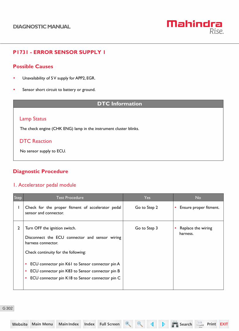
302G
DIAGNOSTIC MANUAL
P1731 - ERROR SENSOR SUPPLY 1
Possible Causes
• Unavailability of 5 V supply for APP2, EGR.
• Sensor short circuit to battery or ground.
DTC Information
Lamp Status
The check engine (CHK ENG) lamp in the instrument cluster blinks.
DTC Reaction
No sensor supply to ECU.
Diagnostic Procedure
1. Accelerator pedal module
2 Turn OFF the ignition switch.
Disconnect the ECU connector and sensor wiring harness connector.
Check continuity for the following:
• ECU connector pin K61 to Sensor connector pin A
• ECU connector pin K83 to Sensor connector pin B
• ECU connector pin K18 to Sensor connector pin C
Go to Step 3 • Replace the wiring harness.
Step Test Procedure Yes No
1 Go to Step 2 • Ensure proper fitment.Check for the proper fitment of accelerator pedal sensor and connector.
230https://www.truck-manuals.net/
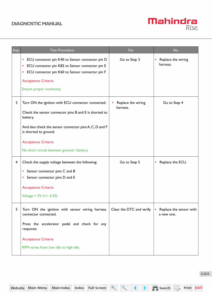
303G
DIAGNOSTIC MANUAL
3
• ECU connector pin K40 to Sensor connector pin D
• ECU connector pin K82 to Sensor connector pin E
• ECU connector pin K60 to Sensor connector pin F
Turn ON the ignition with ECU connector connected.
Check the sensor connector pins B and E is shorted to battery.
And also check the sensor connector pins A, C, D and F is shorted to ground.
Go to Step 3
Go to Step 4
• Replace the wiring harness.
• Replace the wiring harness.
Acceptance Criteria
Ensure proper continuity.
Acceptance Criteria
No short circuit between ground / battery.
Step Test Procedure Yes No
5 Turn ON the ignition with sensor wiring harness connector connected.
Press the accelerator pedal and check for any response.
Clear the DTC and verify. • Replace the sensor with a new one.
• Replace the ECU.4 Check the supply voltage between the following:
• Sensor connector pins C and B
• Sensor connector pins D and E
Go to Step 5
Acceptance Criteria
Voltage = 5V (+/- 0.25)
Acceptance Criteria
RPM varies from low idle to high idle.
231https://www.truck-manuals.net/
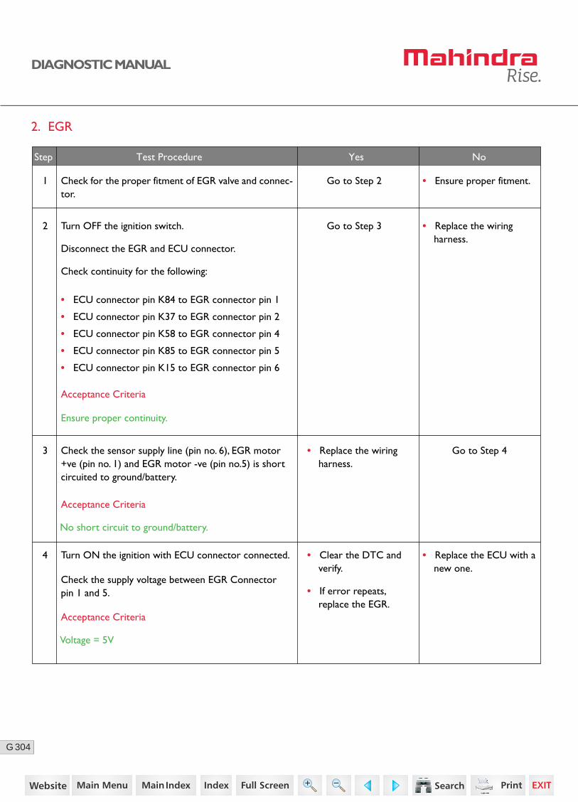
304G
DIAGNOSTIC MANUAL
2. EGR
2 Turn OFF the ignition switch.
Disconnect the EGR and ECU connector.
Check continuity for the following:
• ECU connector pin K84 to EGR connector pin 1
• ECU connector pin K37 to EGR connector pin 2
• ECU connector pin K58 to EGR connector pin 4
• ECU connector pin K85 to EGR connector pin 5
• ECU connector pin K15 to EGR connector pin 6
Go to Step 3
Go to Step 4
• Replace the wiring harness.
4 Turn ON the ignition with ECU connector connected.
Check the supply voltage between EGR Connector pin 1 and 5.
3 Check the sensor supply line (pin no. 6), EGR motor +ve (pin no. 1) and EGR motor -ve (pin no.5) is short circuited to ground/battery.
Acceptance Criteria
Acceptance Criteria
Voltage = 5V
Acceptance Criteria
No short circuit to ground/battery.
Step Test Procedure Yes No
• Replace the wiring harness.
• Clear the DTC and verify.
• If error repeats, replace the EGR.
Ensure proper continuity.
1 Go to Step 2 • Ensure proper fitment.Check for the proper fitment of EGR valve and connec-tor.
• Replace the ECU with a new one.
232https://www.truck-manuals.net/
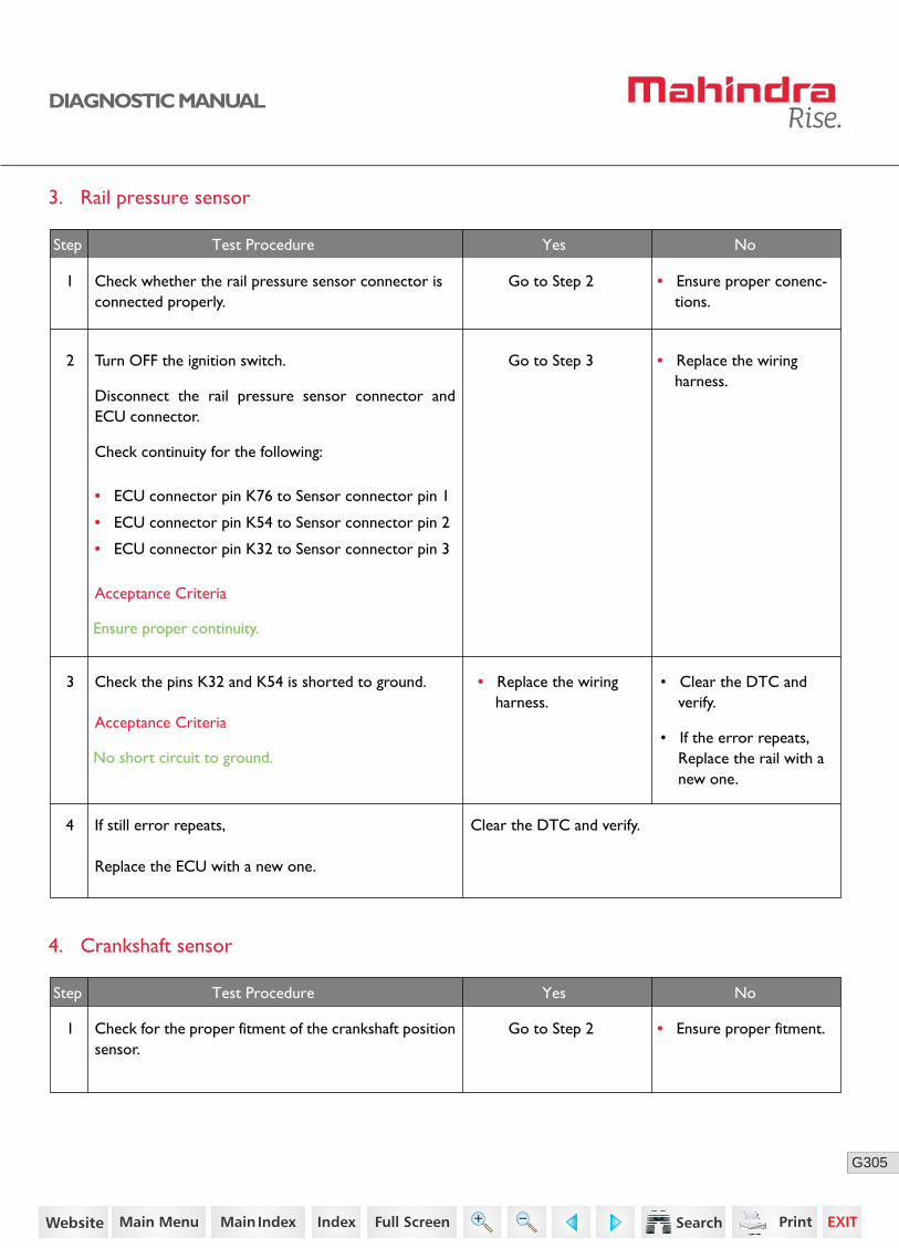
305G
DIAGNOSTIC MANUAL
3. Rail pressure sensor
4. Crankshaft sensor
1 Check for the proper fitment of the crankshaft position sensor.
Go to Step 2 • Ensure proper fitment.
Step Test Procedure Yes No
2 Turn OFF the ignition switch.
Disconnect the rail pressure sensor connector and ECU connector.
Check continuity for the following:
• ECU connector pin K76 to Sensor connector pin 1
• ECU connector pin K54 to Sensor connector pin 2
• ECU connector pin K32 to Sensor connector pin 3
Go to Step 3 • Replace the wiring harness.
Go to Step 2 • Ensure proper conenc-tions.
3 Check the pins K32 and K54 is shorted to ground.
Acceptance Criteria
Ensure proper continuity.
Acceptance Criteria
No short circuit to ground.
Step Test Procedure Yes No
• Replace the wiring harness.
• Clear the DTC and verify.
• If the error repeats, Replace the rail with a new one.
4 If still error repeats,
Replace the ECU with a new one.
Clear the DTC and verify.
1 Check whether the rail pressure sensor connector is connected properly.
233https://www.truck-manuals.net/

306G
DIAGNOSTIC MANUAL
2 Turn OFF the ignition switch.
Disconnect the sensor wiring harness connector and ECU connector.
Check continuity for the following:
• ECU connector pin K52 to Sensor connector pin 1
• ECU connector pin K74 to Sensor connector pin 2
• ECU connector pin K30 to Sensor connector pin 3
Go to Step 3
• Replace the wiring harness.
3 Turn ON the ignition with ECU connector connected.
Check for any short circuit for sensor connector pin 1 and 2 with ground/battery.
Check for any short circuit between sensor connector pin 1 and 2.
Go to Step 4
Acceptance Criteria
Ensure proper continuity
Acceptance Criteria
Ensure no short circuits.
• Replace the Sensor with a new one.
4 Check if the gap between the cam sensor tip and cam gear sensing surface.
Go to Step 5
Acceptance Criteria
0.95 to 1.55 mm
Step Test Procedure Yes No
• Replace the wiring harness.
234https://www.truck-manuals.net/
307G
DIAGNOSTIC MANUAL
• Clear the DTC and verify using the FES diagnostic tool.
• Activate the ignition for one driving cycle (ignition-OFF and ON).
Healing Condition
After performing the troubleshooting for each P Code, follow the below test procedure before driving the vehicle.
Upon completion of diagnostic procedure, clear the DTC. Ensure that the problem has been rectified and the DTC does not appear again.
235https://www.truck-manuals.net/
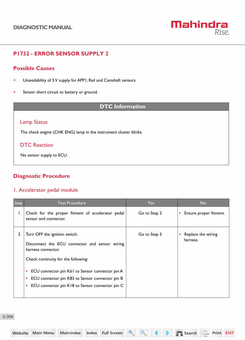
308G
DIAGNOSTIC MANUAL
P1732 - ERROR SENSOR SUPPLY 2
Possible Causes
• Unavailability of 5 V supply for APP1, Rail and Camshaft sensors.
• Sensor short circuit to battery or ground.
DTC Information
Lamp Status
The check engine (CHK ENG) lamp in the instrument cluster blinks.
DTC Reaction
No sensor supply to ECU.
Diagnostic Procedure
1. Accelerator pedal module
2 Turn OFF the ignition switch.
Disconnect the ECU connector and sensor wiring harness connector.
Check continuity for the following:
• ECU connector pin K61 to Sensor connector pin A
• ECU connector pin K83 to Sensor connector pin B
• ECU connector pin K18 to Sensor connector pin C
Go to Step 3 • Replace the wiring harness.
Step Test Procedure Yes No
1 Go to Step 2 • Ensure proper fitment.Check for the proper fitment of accelerator pedal sensor and connector.
236https://www.truck-manuals.net/

309G
DIAGNOSTIC MANUAL
3
• ECU connector pin K40 to Sensor connector pin D
• ECU connector pin K82 to Sensor connector pin E
• ECU connector pin K60 to Sensor connector pin F
Turn ON the ignition with ECU connector connected.
Check the sensor connector pins B and E is shorted to battery.
And also check the sensor connector pins A, C, D and F is shorted to ground.
Go to Step 3
Go to Step 4
• Replace the wiring harness.
• Replace the wiring harness.
Acceptance Criteria
Ensure proper continuity.
Acceptance Criteria
No short circuit between ground / battery.
Step Test Procedure Yes No
5 Turn ON the ignition with sensor wiring harness connector connected.
Press the accelerator pedal and check for any response.
Clear the DTC and verify. • Replace the sensor with a new one.
• Replace the ECU.4 Check the supply voltage between the following:
• Sensor connector pins C and B
• Sensor connector pins D and E
Go to Step 5
Acceptance Criteria
Voltage = 5V (+/- 0.25)
Acceptance Criteria
RPM varies from low idle to high idle.
237https://www.truck-manuals.net/
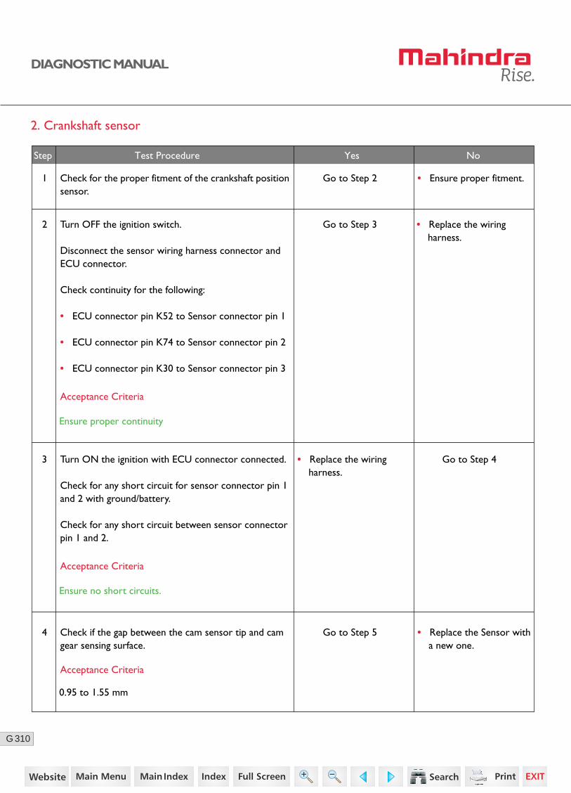
310G
DIAGNOSTIC MANUAL
2. Crankshaft sensor
1 Check for the proper fitment of the crankshaft position sensor.
Go to Step 2 • Ensure proper fitment.
2 Turn OFF the ignition switch.
Disconnect the sensor wiring harness connector and ECU connector.
Check continuity for the following:
• ECU connector pin K52 to Sensor connector pin 1
• ECU connector pin K74 to Sensor connector pin 2
• ECU connector pin K30 to Sensor connector pin 3
Go to Step 3
• Replace the wiring harness.
3 Turn ON the ignition with ECU connector connected.
Check for any short circuit for sensor connector pin 1 and 2 with ground/battery.
Check for any short circuit between sensor connector pin 1 and 2.
Go to Step 4
Acceptance Criteria
Ensure proper continuity
Acceptance Criteria
Ensure no short circuits.
• Replace the Sensor with a new one.
4 Check if the gap between the cam sensor tip and cam gear sensing surface.
Go to Step 5
Acceptance Criteria
0.95 to 1.55 mm
Step Test Procedure Yes No
• Replace the wiring harness.
238https://www.truck-manuals.net/
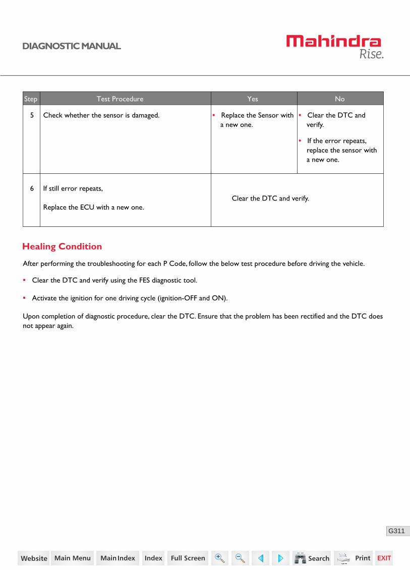
311G
DIAGNOSTIC MANUAL
No
No
No
• Clear the DTC and verify using the FES diagnostic tool.
• Activate the ignition for one driving cycle (ignition-OFF and ON).
Healing Condition
After performing the troubleshooting for each P Code, follow the below test procedure before driving the vehicle.
Upon completion of diagnostic procedure, clear the DTC. Ensure that the problem has been rectified and the DTC does not appear again.
5 Check whether the sensor is damaged.
Step Test Procedure Yes No
• Replace the Sensor with a new one.
• Clear the DTC and verify.
• If the error repeats, replace the sensor with a new one.
6 If still error repeats,
Replace the ECU with a new one.Clear the DTC and verify.
239https://www.truck-manuals.net/
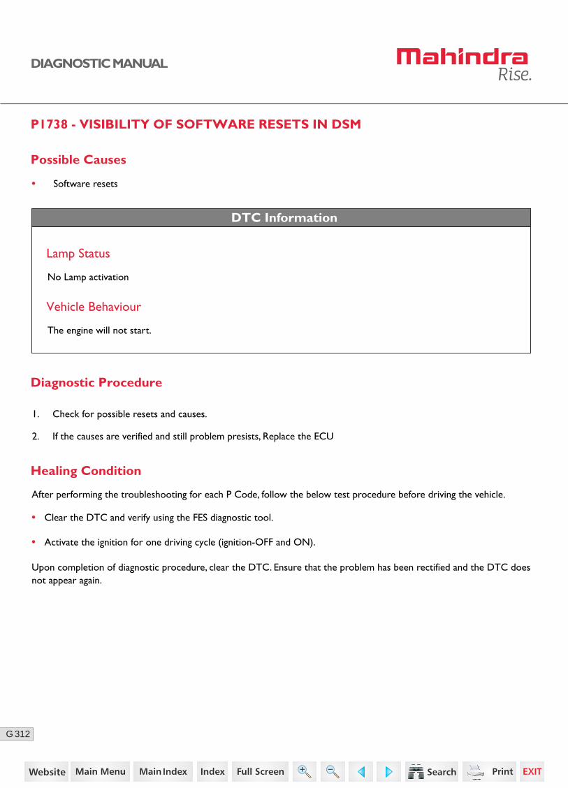
312G
DIAGNOSTIC MANUAL
P1738 - VISIBILITY OF SOFTWARE RESETS IN DSM
Possible Causes
• Software resets
DTC Information
Lamp Status
No Lamp activation
Vehicle Behaviour
The engine will not start.
Diagnostic Procedure
1. Check for possible resets and causes.
2. If the causes are verified and still problem presists, Replace the ECU
• Clear the DTC and verify using the FES diagnostic tool.
• Activate the ignition for one driving cycle (ignition-OFF and ON).
Healing Condition
After performing the troubleshooting for each P Code, follow the below test procedure before driving the vehicle.
Upon completion of diagnostic procedure, clear the DTC. Ensure that the problem has been rectified and the DTC does not appear again.
240https://www.truck-manuals.net/
313G
DIAGNOSTIC MANUAL
P1741 - COMMUNICATION SPI ERRORS OF TLE6232
Possible Causes
• Communication errors in Tle6232 chip.
• Tle6232 chip is defective or damaged.
DTC Information
Lamp Status
No Lamp activation
Vehicle Behaviour
The engine will not start.
Diagnostic Procedure
1. Clear the error through the diagnostic tester.
2. If the problem persists, replace the ECU.
• Clear the DTC and verify using the FES diagnostic tool.
• Activate the ignition for one driving cycle (ignition-OFF and ON).
Healing Condition
After performing the troubleshooting for each P Code, follow the below test procedure before driving the vehicle.
Upon completion of diagnostic procedure, clear the DTC. Ensure that the problem has been rectified and the DTC does not appear again.
241https://www.truck-manuals.net/
314G
DIAGNOSTIC MANUAL
P1742 - INJECTION CUT OFF DEMAND (ICO) FOR SHUT OFF COORDINATOR
Possible Causes
• Overrun monitoring fault (DFC_MoFOvR) will trigger this error.
DTC Information
Lamp Status
The check engine (CHK ENG) lamp in the instrument cluster glows continuously.
Vehicle Behaviour
The engine will not start.
Diagnostic Procedure
1. Clear the error through the diagnostic tester.
2. If the problem persists, replace the ECU.
• Clear the DTC and verify using the FES diagnostic tool.
• Activate the ignition for one driving cycle (ignition-OFF and ON).
Healing Condition
After performing the troubleshooting for each P Code, follow the below test procedure before driving the vehicle.
Upon completion of diagnostic procedure, clear the DTC. Ensure that the problem has been rectified and the DTC does not appear again.
242https://www.truck-manuals.net/
315G
DIAGNOSTIC MANUAL
P1743 - ERROR IS THE PLAUSIBILITY BETWEEN ENGINE SPEED IN LEVEL 1 AND LEVEL 2
Possible Causes
• Error in the engine speed acquisition from the crank sensor.
DTC Information
Lamp Status
No Lamp activation
Vehicle Behaviour
The engine will not start.
Diagnostic Procedure
1. Clear the error through the diagnostic tester.
2. If the problem persists, replace the ECU.
• Clear the DTC and verify using the FES diagnostic tool.
• Activate the ignition for one driving cycle (ignition-OFF and ON).
Healing Condition
After performing the troubleshooting for each P Code, follow the below test procedure before driving the vehicle.
Upon completion of diagnostic procedure, clear the DTC. Ensure that the problem has been rectified and the DTC does not appear again.
243https://www.truck-manuals.net/
316G
DIAGNOSTIC MANUAL
P1750 - ERROR IN THE PLAUSIBILITY OF CURRENT ENERGIZING TIME WITH MAXIMUM PERMITTED ENERGIZINGTIME
Possible Causes
• Error in the plausibility of current energizing time with maximum permitted energizing time during overrun.
• The ECU has an internal error.
DTC Information
Lamp Status
The check engine (CHK ENG) lamp in the instrument cluster glows continuously.
Vehicle Behaviour
The engine will not start.
Diagnostic Procedure
1. Clear the error through the diagnostic tester.
2. If the problem persists, replace the ECU.
• Clear the DTC and verify using the FES diagnostic tool.
• Activate the ignition for one driving cycle (ignition-OFF and ON).
Healing Condition
After performing the troubleshooting for each P Code, follow the below test procedure before driving the vehicle.
Upon completion of diagnostic procedure, clear the DTC. Ensure that the problem has been rectified and the DTC does not appear again.
244https://www.truck-manuals.net/
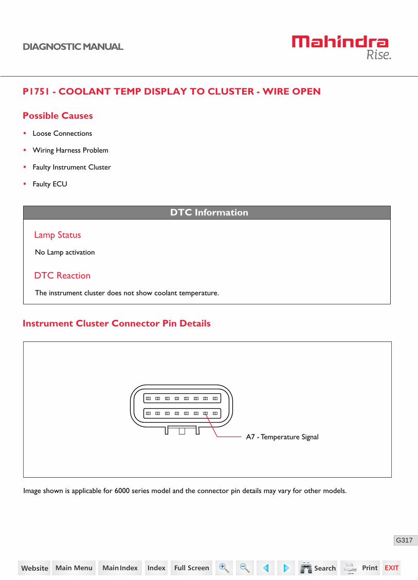
317G
DIAGNOSTIC MANUAL
P1751 - COOLANT TEMP DISPLAY TO CLUSTER - WIRE OPEN
Possible Causes
• Loose Connections
• Wiring Harness Problem
• Faulty Instrument Cluster
• Faulty ECU
DTC Information
DTC Reaction
The instrument cluster does not show coolant temperature.
A7 - Temperature Signal
Lamp Status
No Lamp activation
Instrument Cluster Connector Pin Details
Image shown is applicable for 6000 series model and the connector pin details may vary for other models.
245https://www.truck-manuals.net/
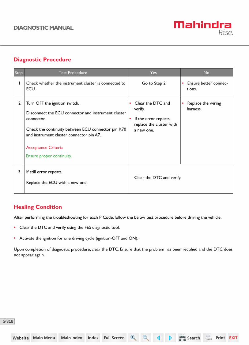
318G
DIAGNOSTIC MANUAL
3
• Clear the DTC and verify.
• If the error repeats, replace the cluster with a new one.
No
• Clear the DTC and verify using the FES diagnostic tool.
• Activate the ignition for one driving cycle (ignition-OFF and ON).
Healing Condition
After performing the troubleshooting for each P Code, follow the below test procedure before driving the vehicle.
Upon completion of diagnostic procedure, clear the DTC. Ensure that the problem has been rectified and the DTC does not appear again.
Diagnostic Procedure
2 Turn OFF the ignition switch.
Disconnect the ECU connector and instrument cluster connector.
Check the continuity between ECU connector pin K70 and instrument cluster connector pin A7.
• Replace the wiring harness.
1 Check whether the instrument cluster is connected to ECU.
Go to Step 2 • Ensure better connec-tions.
Acceptance Criteria
Ensure proper continuity.
Step Test Procedure Yes No
If still error repeats,
Replace the ECU with a new one.Clear the DTC and verify.
246https://www.truck-manuals.net/
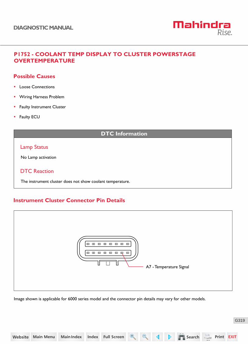
319G
DIAGNOSTIC MANUAL
P1752 - COOLANT TEMP DISPLAY TO CLUSTER POWERSTAGE OVERTEMPERATURE
Possible Causes
• Loose Connections
• Wiring Harness Problem
• Faulty Instrument Cluster
• Faulty ECU
DTC Information
DTC Reaction
The instrument cluster does not show coolant temperature.
A7 - Temperature Signal
Lamp Status
No Lamp activation
Instrument Cluster Connector Pin Details
Image shown is applicable for 6000 series model and the connector pin details may vary for other models.
247https://www.truck-manuals.net/
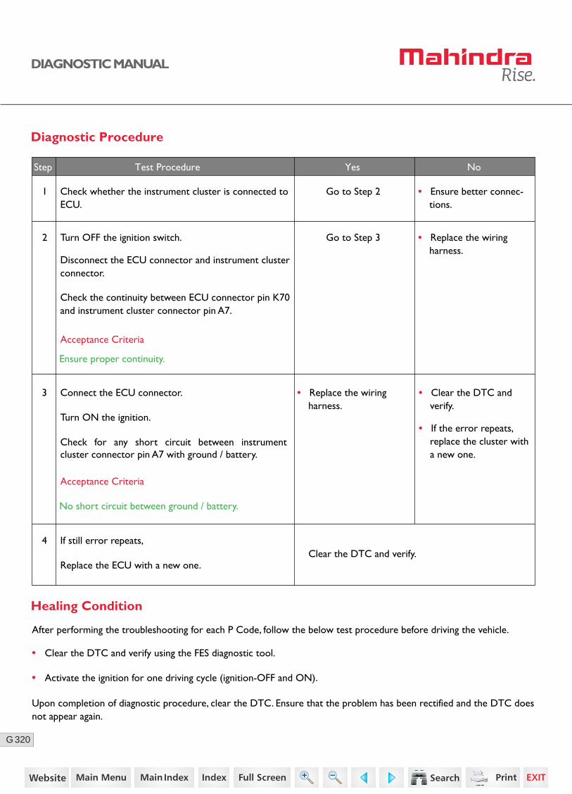
320G
DIAGNOSTIC MANUAL
3 Connect the ECU connector.
Turn ON the ignition.
Check for any short circuit between instrument cluster connector pin A7 with ground / battery.
• Replace the wiring harness.
No
Diagnostic Procedure
2 Turn OFF the ignition switch.
Disconnect the ECU connector and instrument cluster connector.
Check the continuity between ECU connector pin K70 and instrument cluster connector pin A7.
• Replace the wiring harness.
1 Check whether the instrument cluster is connected to ECU.
Go to Step 2 • Ensure better connec-tions.
Acceptance Criteria
Ensure proper continuity.
Step Test Procedure Yes No
Go to Step 3
Acceptance Criteria
No short circuit between ground / battery.
4
• Clear the DTC and verify.
• If the error repeats, replace the cluster with a new one.
If still error repeats,
Replace the ECU with a new one.Clear the DTC and verify.
• Clear the DTC and verify using the FES diagnostic tool.
• Activate the ignition for one driving cycle (ignition-OFF and ON).
Healing Condition
After performing the troubleshooting for each P Code, follow the below test procedure before driving the vehicle.
Upon completion of diagnostic procedure, clear the DTC. Ensure that the problem has been rectified and the DTC does not appear again.
248https://www.truck-manuals.net/
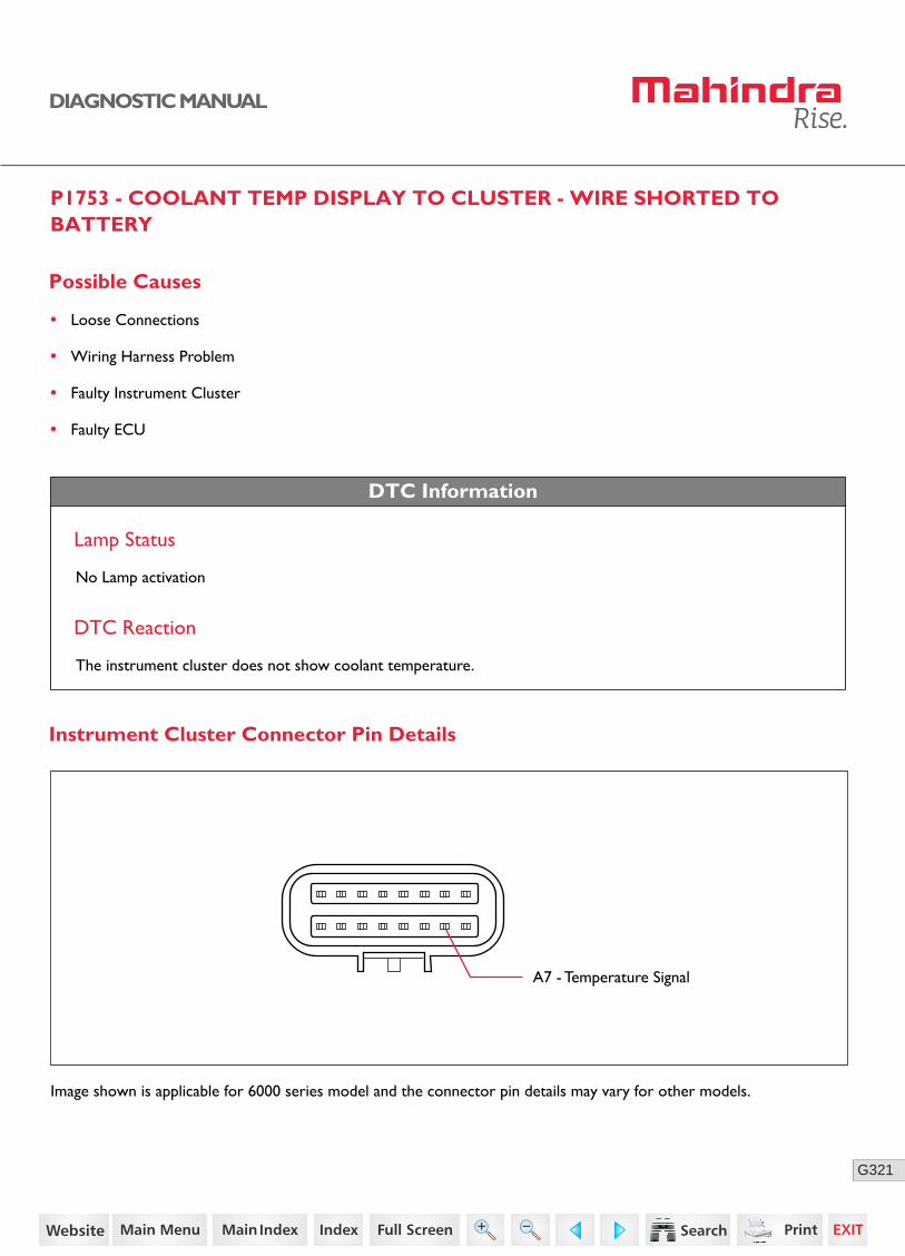
321G
DIAGNOSTIC MANUAL
P1753 - COOLANT TEMP DISPLAY TO CLUSTER - WIRE SHORTED TO BATTERY
Possible Causes
• Loose Connections
• Wiring Harness Problem
• Faulty Instrument Cluster
• Faulty ECU
DTC Information
DTC Reaction
The instrument cluster does not show coolant temperature.
A7 - Temperature Signal
Lamp Status
No Lamp activation
Instrument Cluster Connector Pin Details
Image shown is applicable for 6000 series model and the connector pin details may vary for other models.
249https://www.truck-manuals.net/

322G
DIAGNOSTIC MANUAL
3 Connect the ECU connector.
Turn ON the ignition.
Check for any short circuit between instrument cluster connector pin A7 with ground / battery.
• Replace the wiring harness.
No
Diagnostic Procedure
2 Turn OFF the ignition switch.
Disconnect the ECU connector and instrument cluster connector.
Check the continuity between ECU connector pin K70 and instrument cluster connector pin A7.
• Replace the wiring harness.
1 Check whether the instrument cluster is connected to ECU.
Go to Step 2 • Ensure better connec-tions.
Acceptance Criteria
Ensure proper continuity.
Step Test Procedure Yes No
Go to Step 3
Acceptance Criteria
No short circuit between ground / battery.
4
• Clear the DTC and verify.
• If the error repeats, replace the cluster with a new one.
If still error repeats,
Replace the ECU with a new one.Clear the DTC and verify.
• Clear the DTC and verify using the FES diagnostic tool.
• Activate the ignition for one driving cycle (ignition-OFF and ON).
Healing Condition
After performing the troubleshooting for each P Code, follow the below test procedure before driving the vehicle.
Upon completion of diagnostic procedure, clear the DTC. Ensure that the problem has been rectified and the DTC does not appear again.
250https://www.truck-manuals.net/
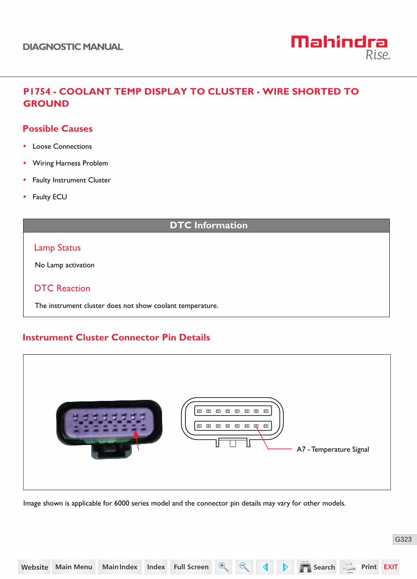
323G
DIAGNOSTIC MANUAL
P1754 - COOLANT TEMP DISPLAY TO CLUSTER - WIRE SHORTED TO GROUND
Possible Causes
• Loose Connections
• Wiring Harness Problem
• Faulty Instrument Cluster
• Faulty ECU
DTC Information
DTC Reaction
The instrument cluster does not show coolant temperature.
A7 - Temperature Signal
Lamp Status
No Lamp activation
Instrument Cluster Connector Pin Details
Image shown is applicable for 6000 series model and the connector pin details may vary for other models.
251https://www.truck-manuals.net/

324G
DIAGNOSTIC MANUAL
3 Connect the ECU connector.
Turn ON the ignition.
Check for any short circuit between instrument cluster connector pin A7 with ground / battery.
• Replace the wiring harness.
No
Diagnostic Procedure
2 Turn OFF the ignition switch.
Disconnect the ECU connector and instrument cluster connector.
Check the continuity between ECU connector pin K70 and instrument cluster connector pin A7.
• Replace the wiring harness.
1 Check whether the instrument cluster is connected to ECU.
Go to Step 2 • Ensure better connec-tions.
Acceptance Criteria
Ensure proper continuity.
Step Test Procedure Yes No
Go to Step 3
Acceptance Criteria
No short circuit between ground / battery.
4
• Clear the DTC and verify.
• If the error repeats, replace the cluster with a new one.
If still error repeats,
Replace the ECU with a new one.Clear the DTC and verify.
• Clear the DTC and verify using the FES diagnostic tool.
• Activate the ignition for one driving cycle (ignition-OFF and ON).
Healing Condition
After performing the troubleshooting for each P Code, follow the below test procedure before driving the vehicle.
Upon completion of diagnostic procedure, clear the DTC. Ensure that the problem has been rectified and the DTC does not appear again.
252https://www.truck-manuals.net/
325G
DIAGNOSTIC MANUAL
P1801 - TOTAL COUNTER FOR RAIL PRESSURE LIMITING VALVE OPEN CONDITION EXCEEDED THE LIMIT
Possible Causes
• Total counter for PRV open condition exceeds the limit.
DTC Information
Lamp Status
The Check engine (CHK ENG) lamp in the instrument cluster blinks continuously.
DTC Reaction
Rail line needs to be changed after 50 counters.
Diagnostic Procedure
1. Clear the DTC and verify.
2. Replace the rail.
• Clear the DTC and verify using the FES diagnostic tool.
• Activate the ignition for one driving cycle (ignition-OFF and ON).
Healing Condition
After performing the troubleshooting for each P Code, follow the below test procedure before driving the vehicle.
Upon completion of diagnostic procedure, clear the DTC. Ensure that the problem has been rectified and the DTC does not appear again.
253https://www.truck-manuals.net/
326G
DIAGNOSTIC MANUAL
P1802 - RAIL PRESSURE LIMITING VALVE FORCED OPEN
DTC Information
Lamp Status
The Check engine (CHK ENG) lamp in the instrument cluster blinks continuously.
DTC Reaction
Rail line needs to be changed after 50 counters.
Diagnostic Procedure
Possible Causes
• Loose connections
• Wiring harness problem
• Metering unit pump failure
• Rail pressure sensor failure
2 Go to Step 3
Go to Step 2
• Replace the wiring harness.
Step Test Procedure Yes No
Turn OFF the ignition switch.
Disconnect the ECU connector and metering unit pump connector.
• Check the continuity between metering unit pump connector pin 1 and ECU connector pin K89.
1 Rectify the same.Clear the DTC and verify
Check for any fuel metering unit (high pressure pump) and rail pressure sensor related errors in diagnostic tester tool.
Acceptance Criteria
Ensure proper continuity.
254https://www.truck-manuals.net/
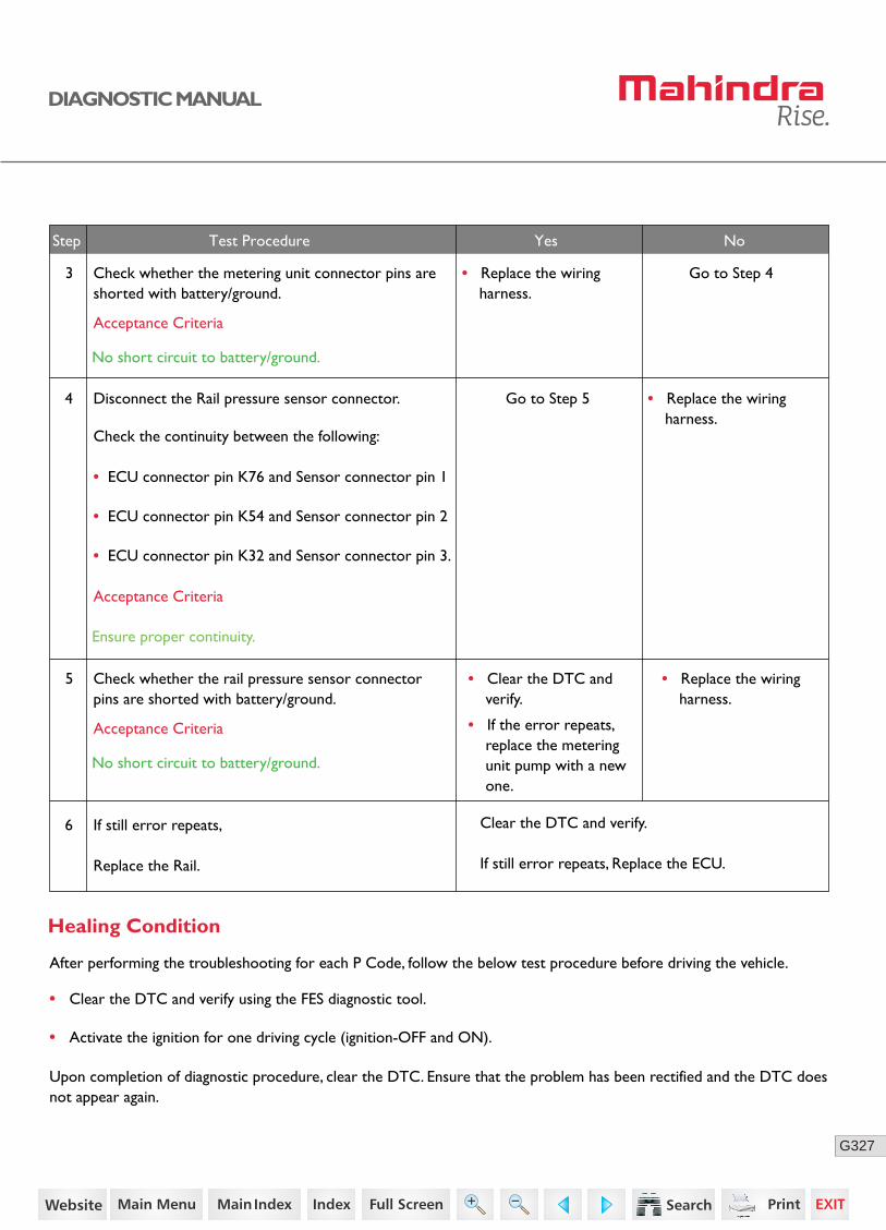
327G
DIAGNOSTIC MANUAL
6
4
• Clear the DTC and verify.
Clear the DTC and verify.
If still error repeats, Replace the ECU.
• If the error repeats, replace the metering unit pump with a new one.
Step Test Procedure Yes No
• Clear the DTC and verify using the FES diagnostic tool.
• Activate the ignition for one driving cycle (ignition-OFF and ON).
Healing Condition
After performing the troubleshooting for each P Code, follow the below test procedure before driving the vehicle.
Upon completion of diagnostic procedure, clear the DTC. Ensure that the problem has been rectified and the DTC does not appear again.
Disconnect the Rail pressure sensor connector.
Check the continuity between the following:
• ECU connector pin K76 and Sensor connector pin 1
• ECU connector pin K54 and Sensor connector pin 2
• ECU connector pin K32 and Sensor connector pin 3.
If still error repeats,
Replace the Rail.
• Replace the wiring harness.
Acceptance Criteria
Ensure proper continuity.
Check whether the metering unit connector pins are shorted with battery/ground.
3 • Replace the wiring harness.
Go to Step 4
Go to Step 5
Acceptance Criteria
No short circuit to battery/ground.
Check whether the rail pressure sensor connector pins are shorted with battery/ground.
5 • Replace the wiring harness.
Acceptance Criteria
No short circuit to battery/ground.
255https://www.truck-manuals.net/
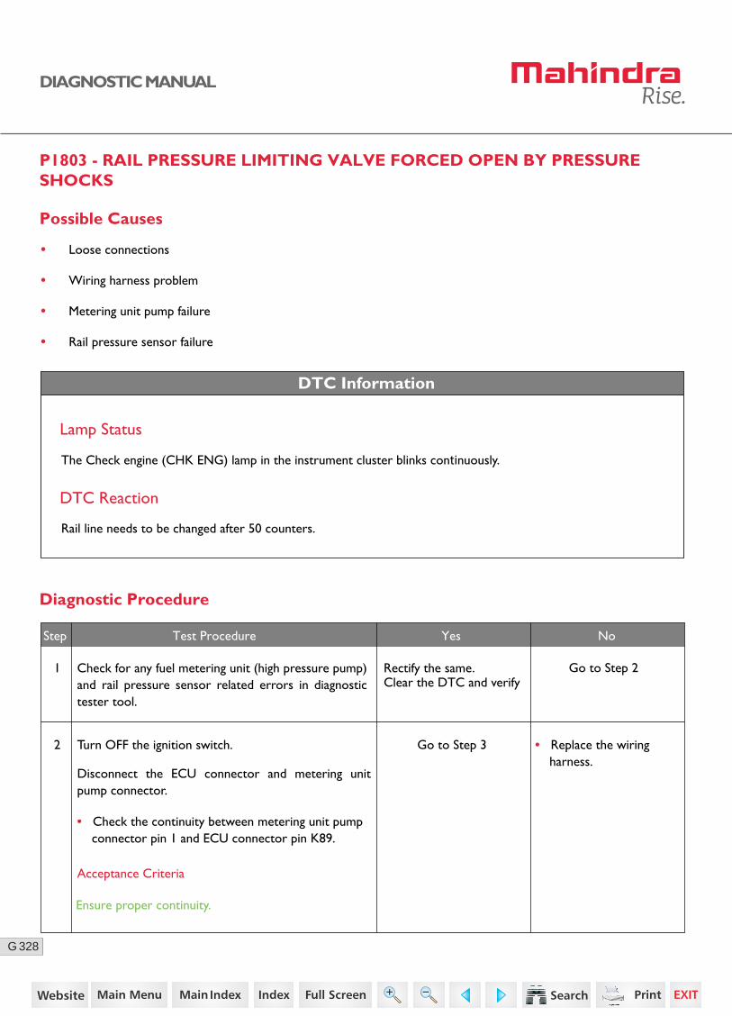
328G
DIAGNOSTIC MANUAL
P1803 - RAIL PRESSURE LIMITING VALVE FORCED OPEN BY PRESSURE SHOCKS
DTC Information
Lamp Status
The Check engine (CHK ENG) lamp in the instrument cluster blinks continuously.
DTC Reaction
Rail line needs to be changed after 50 counters.
Possible Causes
• Loose connections
• Wiring harness problem
• Metering unit pump failure
• Rail pressure sensor failure
Diagnostic Procedure
2 Go to Step 3
Go to Step 2
• Replace the wiring harness.
Step Test Procedure Yes No
Turn OFF the ignition switch.
Disconnect the ECU connector and metering unit pump connector.
• Check the continuity between metering unit pump connector pin 1 and ECU connector pin K89.
1 Rectify the same.Clear the DTC and verify
Check for any fuel metering unit (high pressure pump) and rail pressure sensor related errors in diagnostic tester tool.
Acceptance Criteria
Ensure proper continuity.
256https://www.truck-manuals.net/
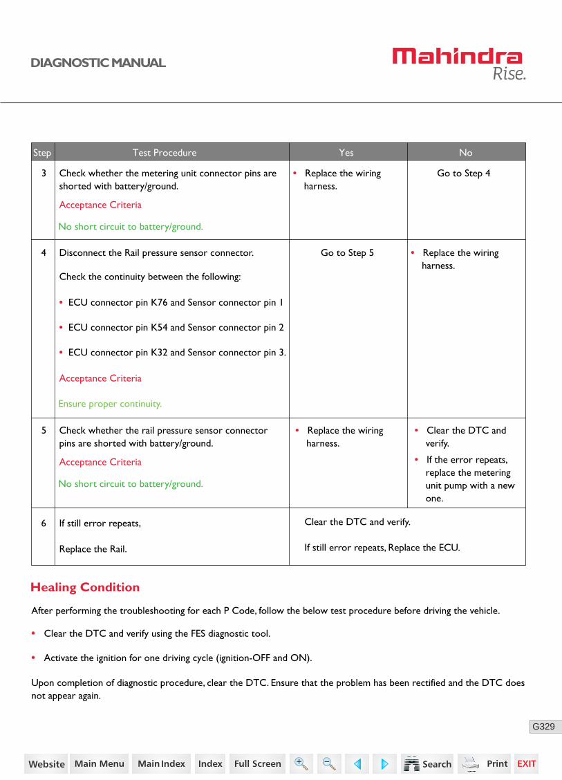
329G
DIAGNOSTIC MANUAL
6
4
• Clear the DTC and verify.
Clear the DTC and verify.
If still error repeats, Replace the ECU.
• If the error repeats, replace the metering unit pump with a new one.
Step Test Procedure Yes No
• Clear the DTC and verify using the FES diagnostic tool.
• Activate the ignition for one driving cycle (ignition-OFF and ON).
Healing Condition
After performing the troubleshooting for each P Code, follow the below test procedure before driving the vehicle.
Upon completion of diagnostic procedure, clear the DTC. Ensure that the problem has been rectified and the DTC does not appear again.
Disconnect the Rail pressure sensor connector.
Check the continuity between the following:
• ECU connector pin K76 and Sensor connector pin 1
• ECU connector pin K54 and Sensor connector pin 2
• ECU connector pin K32 and Sensor connector pin 3.
If still error repeats,
Replace the Rail.
• Replace the wiring harness.
Acceptance Criteria
Ensure proper continuity.
Check whether the metering unit connector pins are shorted with battery/ground.
3 • Replace the wiring harness.
Go to Step 4
Go to Step 5
Acceptance Criteria
No short circuit to battery/ground.
Check whether the rail pressure sensor connector pins are shorted with battery/ground.
5 • Replace the wiring harness.
Acceptance Criteria
No short circuit to battery/ground.
257https://www.truck-manuals.net/
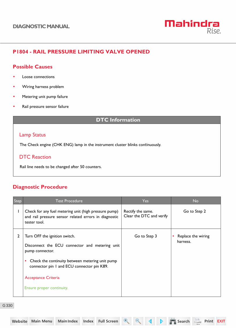
330G
DIAGNOSTIC MANUAL
P1804 - RAIL PRESSURE LIMITING VALVE OPENED
DTC Information
Lamp Status
The Check engine (CHK ENG) lamp in the instrument cluster blinks continuously.
DTC Reaction
Rail line needs to be changed after 50 counters.
Possible Causes
• Loose connections
• Wiring harness problem
• Metering unit pump failure
• Rail pressure sensor failure
Diagnostic Procedure
2 Go to Step 3
Go to Step 2
• Replace the wiring harness.
Step Test Procedure Yes No
Turn OFF the ignition switch.
Disconnect the ECU connector and metering unit pump connector.
• Check the continuity between metering unit pump connector pin 1 and ECU connector pin K89.
1 Rectify the same.Clear the DTC and verify
Check for any fuel metering unit (high pressure pump) and rail pressure sensor related errors in diagnostic tester tool.
Acceptance Criteria
Ensure proper continuity.
258https://www.truck-manuals.net/
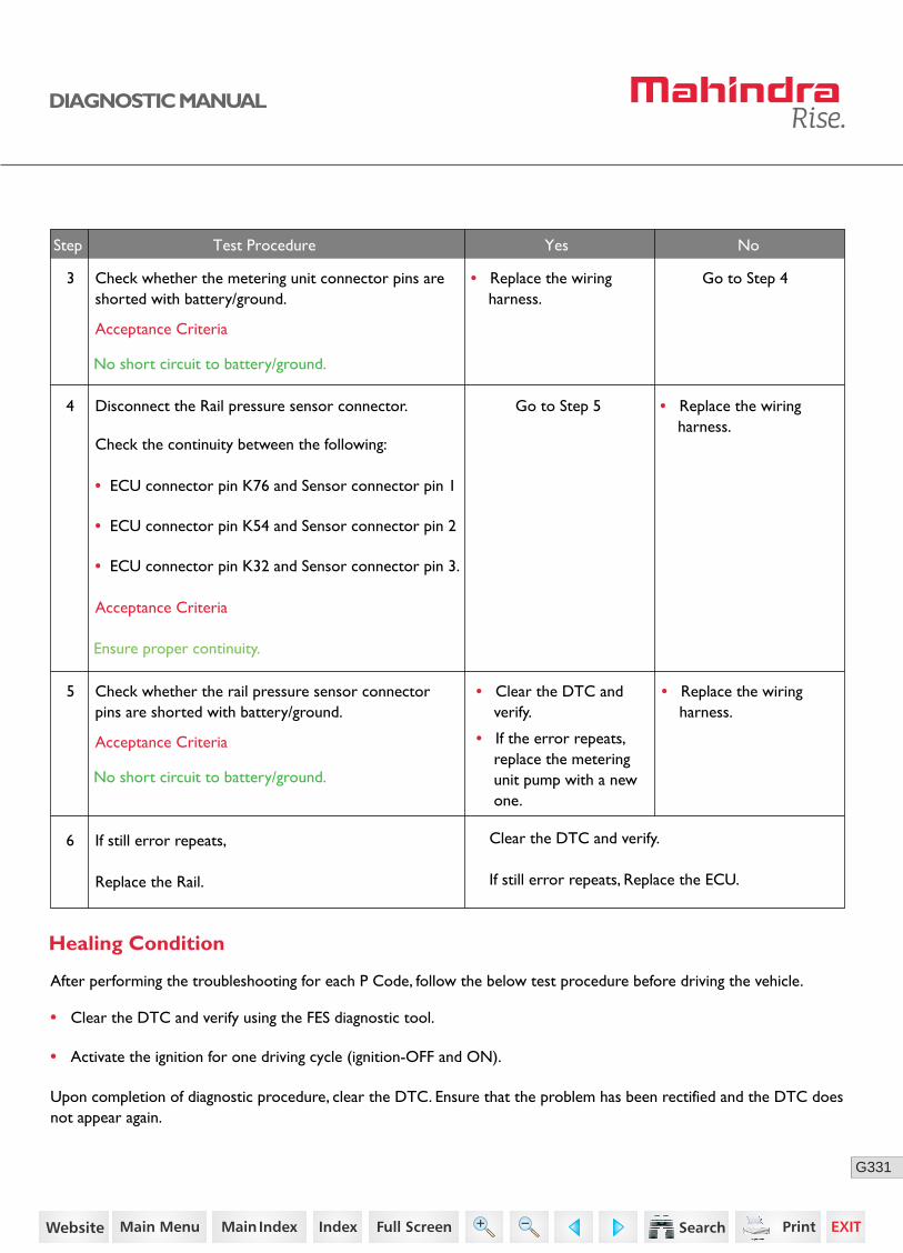
331G
DIAGNOSTIC MANUAL
• Clear the DTC and verify using the FES diagnostic tool.
• Activate the ignition for one driving cycle (ignition-OFF and ON).
Healing Condition
After performing the troubleshooting for each P Code, follow the below test procedure before driving the vehicle.
Upon completion of diagnostic procedure, clear the DTC. Ensure that the problem has been rectified and the DTC does not appear again.
6
4
• Clear the DTC and verify.
Clear the DTC and verify.
If still error repeats, Replace the ECU.
• If the error repeats, replace the metering unit pump with a new one.
Step Test Procedure Yes No
Disconnect the Rail pressure sensor connector.
Check the continuity between the following:
• ECU connector pin K76 and Sensor connector pin 1
• ECU connector pin K54 and Sensor connector pin 2
• ECU connector pin K32 and Sensor connector pin 3.
If still error repeats,
Replace the Rail.
• Replace the wiring harness.
Acceptance Criteria
Ensure proper continuity.
Check whether the metering unit connector pins are shorted with battery/ground.
3 • Replace the wiring harness.
Go to Step 4
Go to Step 5
Acceptance Criteria
No short circuit to battery/ground.
Check whether the rail pressure sensor connector pins are shorted with battery/ground.
5 • Replace the wiring harness.
Acceptance Criteria
No short circuit to battery/ground.
259https://www.truck-manuals.net/
332G
DIAGNOSTIC MANUAL
P1805 - QUANTITY BALANCE CHECK IF A SUCCESSFULL PRV OPENING IS ENSURED
Possible Causes
• Malfunction in the pressure relief valve (PRV).
DTC Information
Lamp Status
The CHK ENG lamp in the instrument cluster glows continuously.
DTC Reaction
Rail line needs to be changed after 50 counters.
Diagnostic Procedure
1. Turn OFF the ignition switch.
2. Disconnect the rail pressure sensor connector.
3. Check whether the rail pressure sensor connector pins are shorted with battery/ground.
4. Clear the DTC and verify.
5. Replace the rail.
• Clear the DTC and verify using the FES diagnostic tool.
• Activate the ignition for one driving cycle (ignition-OFF and ON).
Healing Condition
After performing the troubleshooting for each P Code, follow the below test procedure before driving the vehicle.
Upon completion of diagnostic procedure, clear the DTC. Ensure that the problem has been rectified and the DTC does not appear again.
260https://www.truck-manuals.net/
333G
DIAGNOSTIC MANUAL
P1807 - TOTAL TIME FOR RAIL PRESSURE LIMITING VALVE OPEN CONDITION EXCEEDED THE LIMIT
Possible Causes
• Total time for PLV open condition exceeded the limit.
DTC Information
Lamp Status
The Check engine (CHK ENG) lamp in the instrument cluster blinks continuously.
DTC Reaction
Rail line needs to be changed after 50 counters.
Diagnostic Procedure
1. Clear the DTC and verify.
2. Replace the rail.
• Clear the DTC and verify using the FES diagnostic tool.
• Activate the ignition for one driving cycle (ignition-OFF and ON).
Healing Condition
After performing the troubleshooting for each P Code, follow the below test procedure before driving the vehicle.
Upon completion of diagnostic procedure, clear the DTC. Ensure that the problem has been rectified and the DTC does not appear again.
261https://www.truck-manuals.net/
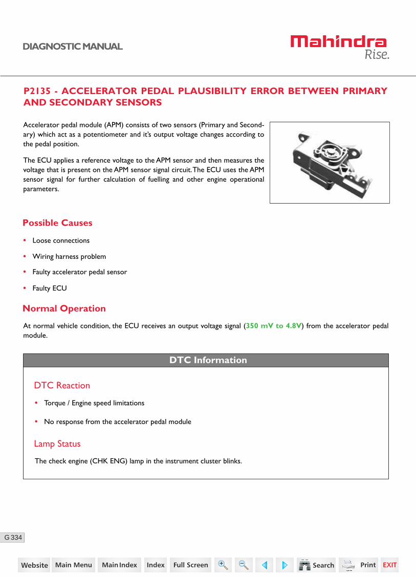
334G
DIAGNOSTIC MANUAL
P2135 - ACCELERATOR PEDAL PLAUSIBILITY ERROR BETWEEN PRIMARY AND SECONDARY SENSORS
Possible Causes
• Loose connections
• Wiring harness problem
• Faulty accelerator pedal sensor
• Faulty ECU
Normal Operation
DTC Information
At normal vehicle condition, the ECU receives an output voltage signal (350 mV to 4.8V) from the accelerator pedal module.
DTC Reaction
• Torque / Engine speed limitations
• No response from the accelerator pedal module
Lamp Status
The check engine (CHK ENG) lamp in the instrument cluster blinks.
Accelerator pedal module (APM) consists of two sensors (Primary and Second-ary) which act as a potentiometer and it’s output voltage changes according to the pedal position.
The ECU applies a reference voltage to the APM sensor and then measures the voltage that is present on the APM sensor signal circuit. The ECU uses the APM sensor signal for further calculation of fuelling and other engine operational parameters.
262https://www.truck-manuals.net/

335G
DIAGNOSTIC MANUAL
Sensor Location
Connector Pin Details
K40
K18
K83
K61Sensor 1 Signal
Primary Sensor
Secondary Sensor
Sensor 2 Signal
Sensor 1 Ground
Sensor 2 Ground
Sensor 1 SupplyAccelerator Pedal Module
ECU
Sensor 2 Supply
K82
K60
A B C D E F
263https://www.truck-manuals.net/
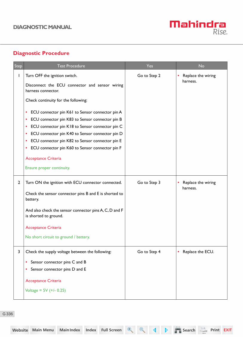
336G
DIAGNOSTIC MANUAL
Diagnostic Procedure
1
2
Turn OFF the ignition switch.
Disconnect the ECU connector and sensor wiring harness connector.
Check continuity for the following:
• ECU connector pin K61 to Sensor connector pin A
• ECU connector pin K83 to Sensor connector pin B
• ECU connector pin K18 to Sensor connector pin C
• ECU connector pin K40 to Sensor connector pin D
• ECU connector pin K82 to Sensor connector pin E
• ECU connector pin K60 to Sensor connector pin F
Turn ON the ignition with ECU connector connected.
Check the sensor connector pins B and E is shorted to battery.
And also check the sensor connector pins A, C, D and F is shorted to ground.
Go to Step 2
Go to Step 3
• Replace the wiring harness.
• Replace the wiring harness.
• Replace the ECU.3 Check the supply voltage between the following:
• Sensor connector pins C and B
• Sensor connector pins D and E
Go to Step 4
Acceptance Criteria
Ensure proper continuity.
Acceptance Criteria
No short circuit to ground / battery.
Acceptance Criteria
Voltage = 5V (+/- 0.25)
Step Test Procedure Yes No
264https://www.truck-manuals.net/
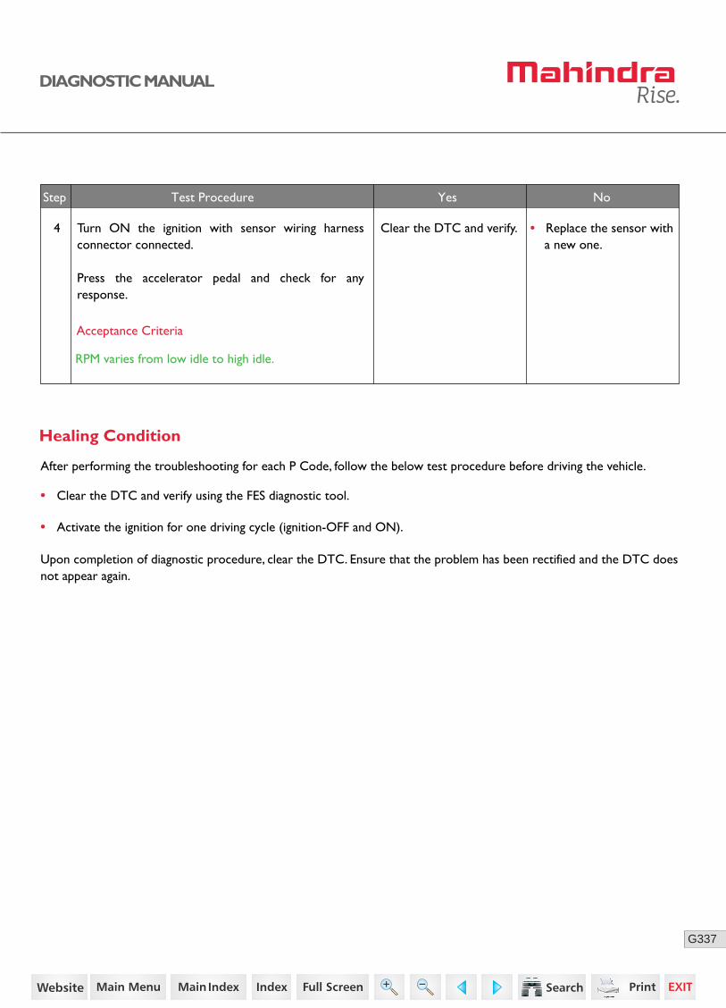
337G
DIAGNOSTIC MANUAL
• Clear the DTC and verify using the FES diagnostic tool.
• Activate the ignition for one driving cycle (ignition-OFF and ON).
Healing Condition
After performing the troubleshooting for each P Code, follow the below test procedure before driving the vehicle.
Upon completion of diagnostic procedure, clear the DTC. Ensure that the problem has been rectified and the DTC does not appear again.
Step Test Procedure Yes No
4 Turn ON the ignition with sensor wiring harness connector connected.
Press the accelerator pedal and check for any response.
Clear the DTC and verify. • Replace the sensor with a new one.
Acceptance Criteria
RPM varies from low idle to high idle.
265https://www.truck-manuals.net/
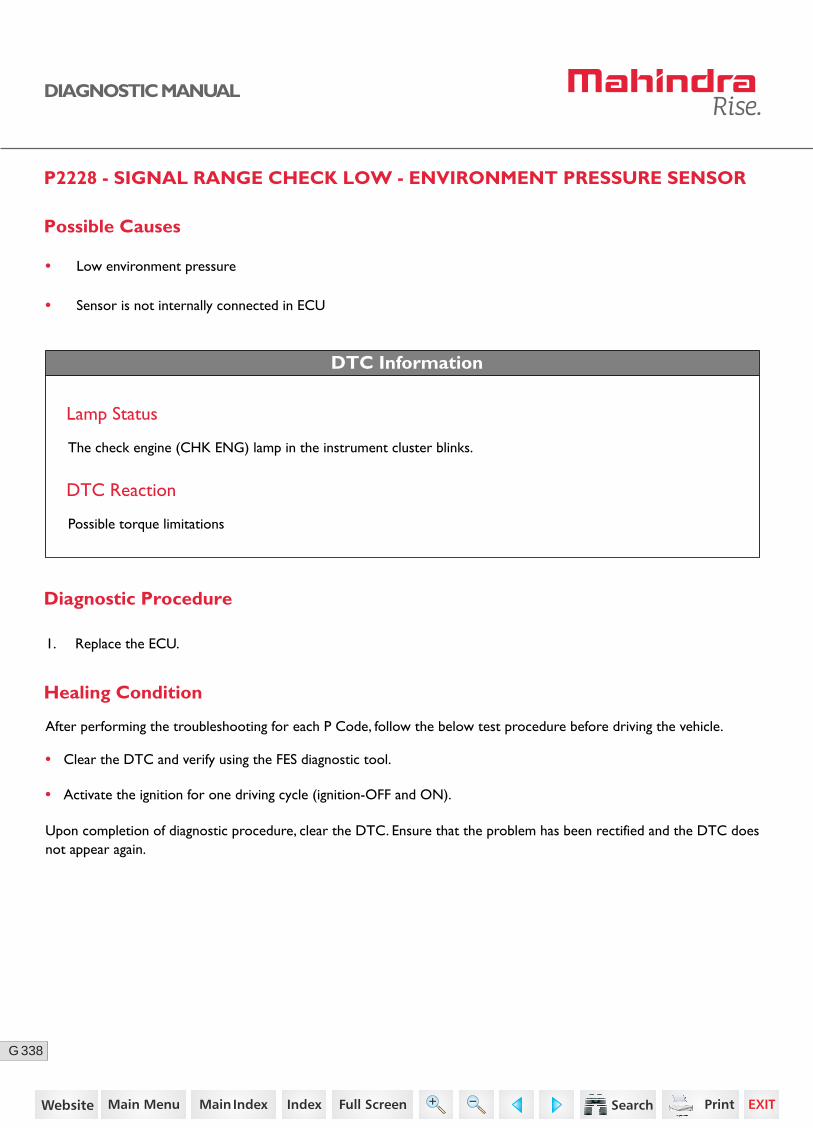
338G
DIAGNOSTIC MANUAL
P2228 - SIGNAL RANGE CHECK LOW - ENVIRONMENT PRESSURE SENSOR
Possible Causes
• Low environment pressure
• Sensor is not internally connected in ECU
DTC Information
Lamp Status
The check engine (CHK ENG) lamp in the instrument cluster blinks.
DTC Reaction
Possible torque limitations
Diagnostic Procedure
1. Replace the ECU.
• Clear the DTC and verify using the FES diagnostic tool.
• Activate the ignition for one driving cycle (ignition-OFF and ON).
Healing Condition
After performing the troubleshooting for each P Code, follow the below test procedure before driving the vehicle.
Upon completion of diagnostic procedure, clear the DTC. Ensure that the problem has been rectified and the DTC does not appear again.
266https://www.truck-manuals.net/
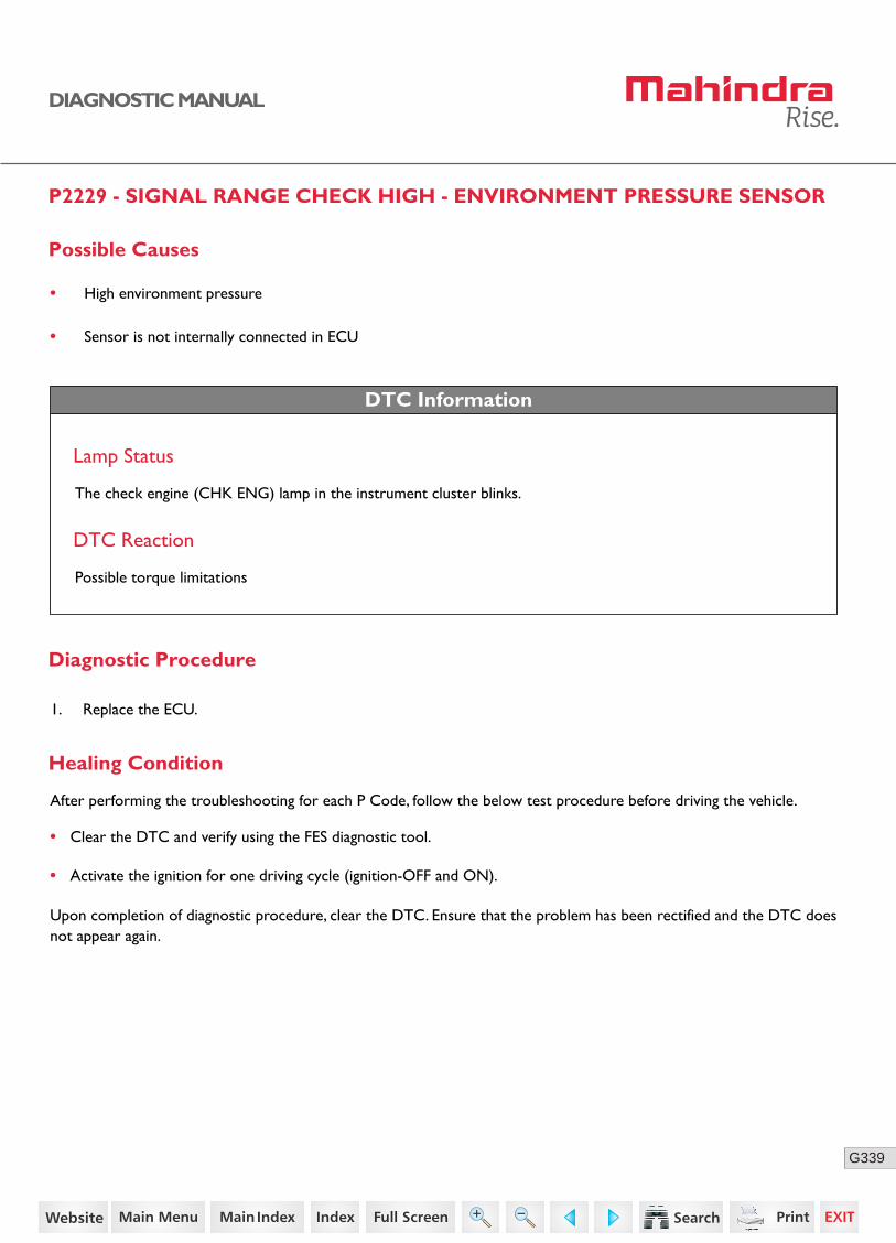
339G
DIAGNOSTIC MANUAL
P2229 - SIGNAL RANGE CHECK HIGH - ENVIRONMENT PRESSURE SENSOR
Possible Causes
• High environment pressure
• Sensor is not internally connected in ECU
DTC Information
Lamp Status
The check engine (CHK ENG) lamp in the instrument cluster blinks.
DTC Reaction
Possible torque limitations
Diagnostic Procedure
1. Replace the ECU.
• Clear the DTC and verify using the FES diagnostic tool.
• Activate the ignition for one driving cycle (ignition-OFF and ON).
Healing Condition
After performing the troubleshooting for each P Code, follow the below test procedure before driving the vehicle.
Upon completion of diagnostic procedure, clear the DTC. Ensure that the problem has been rectified and the DTC does not appear again.
267https://www.truck-manuals.net/
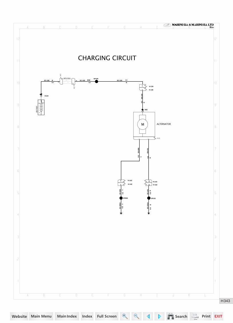
343H
Rise
CHARGING CIRCUIT
H134
1
H841
SP105
H-1361
H2
7
2
H2
7
1
H-1351
SP806
H-1435
H-14211H-1425
H-851 2
H-14311
SP101
BA
TT
ERY
ALTERNATORM
MF6/80ASC-106 R
8.0
EN
-100
R8.0
SC-100R
8.0
SC
-806 Y
0.5
EN
-806
Y0.5
SC
-101 R
0.5
EN
-101
R0.5
SC
-806
A
Y0.
5
SC
-101
A
R0.
5
SC-105 R/W8.0
https://www.truck-manuals.net/
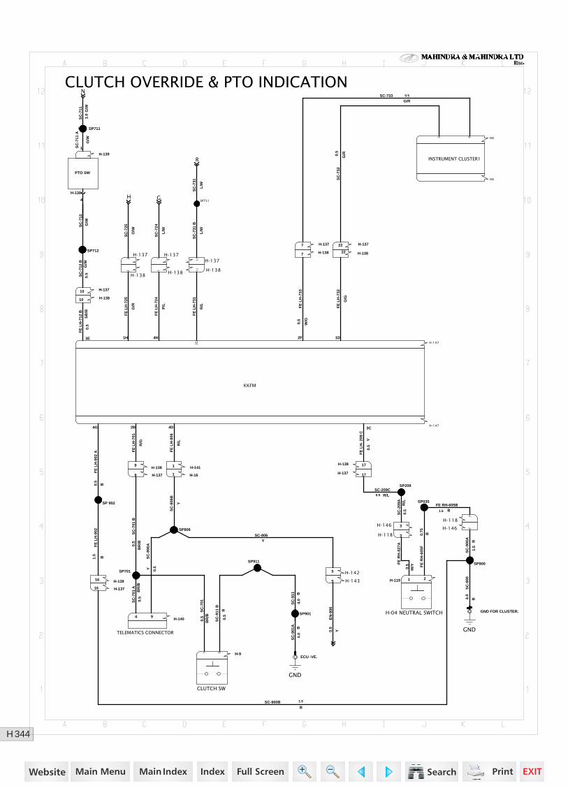
344H
Rise
H
NCLUTCH OVERRIDE & PTO INDICATION
SP 902
SP701
H-1404 9
H-91 2
SP911
H-1411
H-161
ECU -VE.
1
SP806
H-1425
SP209
H-1474G 2B 3C4D
H-1473E 2F 1D1H 4H
2C
H-1435
SP030
H-119 1 2
SP900
GND FOR CLUSTER.
1
H-146 7
H-146 3
H-118 3
H-118
7
SP712
SP711
H-139
1
H-139
4 SP731
H-1377
H-1379
H-13710
H-13822
H-13711
H-137 17
H-137
1
H-138 17
H-13816
H-138
2
H-13722
H-138 11
H-13810
H643
H-1381
H-1389
H6
H-13716
H-1387H-137
2
SP901
INSTRUMENT CLUSTER1
TELEMATICS CONNECTOR
GND
H-04 NEUTRAL SWITCH
GND
CLUTCH SW
PTO SW
KKFM
FE
RH
-605
F0.
75B
FE
LH
-902
A
B0.5
FE
LH
-902
B1.5
SC
-701
BB
R/B0.5
SC
-701
AB
R/B
0.5
SC
-701
BR
/B0.
5
Y 0.5
SC
-806
A
SC
-911
B
B0.
5
SC
-901
A B4.
0
FE
LH
-806
R/L
SC
-806
B
Y
SC-209CR/L0.5
SC
-209
AR
/L0.
5
FE
LH
-701
R/G
FE
LH
- 20
9 C
V0.
5
FE
LH
-712
BS
B/B
0.5
FE
LH
-733
W/G
0.5
FE
LH
-732
O/G
FE
LH
-725
G/R
FE
LH
-724
P/L
FE
LH
-731
R/L
FE
RH
-027
A
0.5
W/Y
SC
-900
A
B1.
5
SC
-900
B4.0
SC-900BB
1.5
SC
-712
BG
/W0.
5
SC
-712
G/W
SC
-711
A
G/W
SC
-731
B
L/W
SC-733G/R0.5
SC
-732
G/R0.
5
SC
-911 B
4.0
FE RH-605BB1.5
EN
-806
Y0.5
SC
-711 G/W
1.0
SC
-725
O/W
SC
-724
L/W
GS
C-7
31
L/W
R
SC-806Y
https://www.truck-manuals.net/
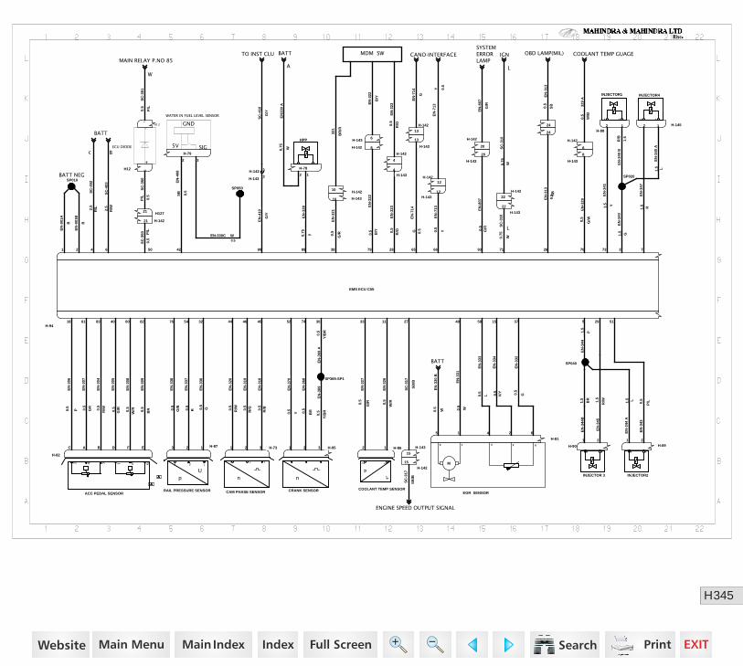
345H
Rise
BATT
BATT NEG
MAIN RELAY P.NO 85CANO-INTERFACE
SYSTEMERRORLAMP
IGN OBD LAMP(MIL) COOLANT TEMP GUAGE
ENGINE SPEED OUTPUT SIGNAL
BATT
MDM SWBATTTO INST CLU
A
A
A
A
A
A
A
A
A
Bc
LW
H12721
H-14221
H-79
2 3
H12 2
H12
1
H-78
12
H-82
C A B FD E H-731 2 3 H-951 2 3
SP369-SP1
H-81
1 245 6
H-14512
H-90
1 2H-89
1 2
SP040
H-8812
H-87123
24
24
H-14210
1 2 4 6 50 42 89 38 79 28 65 66 93 71 26 70 73 3 790
H-142
15
H-143
15
H-14312
H-9418 61 6083 40 82 44 46 45 52 74 30 1133 49 15 3758 295 5176 54 32 27
H-142
20
H-142
22
H-142
8
H-1433
H-143
20
H-142 6
H-143
8
H-142
13
H-143 6
H-142
4
H-142 3H-143
4
H-14310
H-143
22
H-14212
H-143
13
SP010SP020
SP050
H-8612
WATER IN FUEL LEVEL SENSOR
5V SIG
GND
HPP
ACC PEDAL SENSOR
2 4 3 1 65
CAM PHASE SENSOR
n
123
CRANK SENSOR
n
EGR SENSOR
M
1 65 4 2
INJECTOR2
1 2
INJECTOR 3
1 2
INJECTOR4
12
INJECTOR1
12
ECU DIODE
+
-
RAIL PRESSURE SENSOR
p
123
U
EMS ECU C55
COOLANT TEMP SENSOR
U
12
t°
EN
-327
G/R0.
5
SC
-350
P/L 0.5
SC
-350 P
/L0.
5
EN
-408
SB 0.5
EN-330C W0.5
EN
-328
y0.75
EN
-306
P0.5
EN
-307
GR0.5
EN
-304
R/W0.
5
EN
-308
W/R0.5
EN
-305
G/R0.5
EN
-309
BR0.5
EN
-320
R/W0.5
EN
-319
R/G0.
5
EN
-318
R/B0.
5
EN
-370
Y0.5
EN
-368
BR0.5
EN
-369
Y/B
R
0.5
EN
-369
AY
/BR
0.5
EN
-336
O0.5
EN
-337
R0.5
EN
-338
O/B0.5
321
BR
/R
EN
-901
A
B
EN
-901
B
B
EN
-321
G/R0.
5
EN
-410
G/Y
SC
-402
R/L2.
5
SC
-403
R/W2.5
SC
-351
P/L
0.5
EN
330
A
W0.75
SC
-410
G/Y
EN
-344
AL1.5
EN
-344
B1.
5
BR
EN
-331
W0.5
EN
-334
0.5
V/Y
EN
-333
0.5
L
EN
-332
0.5
G
EN
-340
AL1.5
EN
-347
R1.5
EN
-345
R/W1.
5
EN
-343
P/L0.
5
EN
-340
BR
/B
1.5
EN
-341
Y1.5
EN
-326
W/R0.5
EN
-313
SB
0.5
EN
-322
B/Y
0.5
EN
-323
R/O0.
5
EN
-714
G 0.5
EN
-713
Y0.5
EN
-807
G/R0.5 S
C-3
10
W0.75
L
EN
-329
G/W0.5
EN
-340
G1.5
SC
-317
SB
/B
EN
-322
B/Y
EN
-323
R/O0.
5
EN
-713
Y 0.5
EN
-714
G
SC
-310
W0.75
EN
-313
SB0.5 32
9 A
W/B
0.5
EN
-807
G/R
EN
-330
B
W0.5
EN
-344
P1.5
SC
-317
SB
/B
https://www.truck-manuals.net/
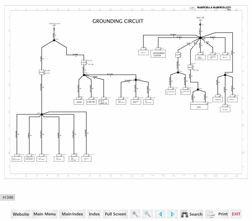
346H
Rise
KKFM REGPLATE LAMP
INSTRUMENTCLUSTER
H-1 HEAD LAMPRH
COM SW1
MOBILE CHARGER
ECU
TELEMATICS CON
HAZARD SW
COM SW2
COM SW1
H-01REARTAIL LAMP
H-03P & T LAMP
H-02PLOUGH LAMP
NEUTRAL SW
WATER IN FUELLEVEL SENSOR
AIRCLOG SW1
GROUNDING CIRCUIT
REARCOM LAMP LH
H-147
4G H-694
4 WD SW
SP902
SP903
H-1255 H-682
SP901
H22
H714
H -2
4
H-1512
H-124
1
H-13
2
H-152
2
H-941 2
H-15312
SP911
H-10
1 H -25
H-122
3
SP030
H-1192H-1202
SP900
H-791 H-761
H-1263
H-1212
3
H-1273
3
H-702
H -32
SP010
H-118
7
H-1467
SP010
H-13816
H-13716
H-1503
P & T LAMP LH
SEVEN POLE SOCKET
ECU -VE
H-2 HEAD LAMPLH
SMS SW
GROUND FOR CLUSTER
FE LH-903AB
FE
LH
-903
B
B
FE
LH
-903
C
B
FE
LH
-902
A
B
FE
LH
-902
E
B
FE
LH
-902
B
BFE LH-902G
SC
-911
B
SC
-901
A
B
SC
-901
C
B
SC-901BB SC-901G
B
SC-901FB
SC-901DB
SC
-901
B
SC-901EB
EN
-901
BE
N-9
01A
B
EN
-901
B
B
SC
-911
E
B
SC
-911
A
B
SC
-911
C
B
FE
RH
-605
E
B
FE
RH
-605
D
B
FE
RH
-605
F
B
FE
RH
-605
B
B
FE
RH
-605
C
B
EN
-902
A
B
EN
-902
B
B
SC
-900
B
SC
-900
A
B
H/L
PIG
-605
B
B
H/L
PIG
-605
B
H/L
PIG
-605
A
B
SC-900BB
FE LH-903B
https://www.truck-manuals.net/
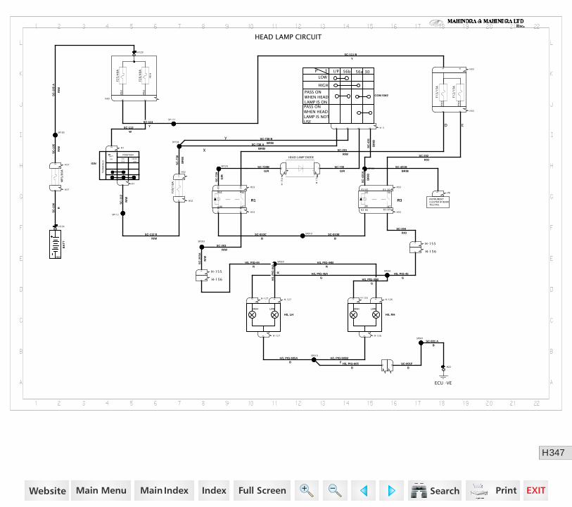
347H
Rise
HEAD LAMP CIRCUIT
INSTRUMENTCLUSTER HI BEAMTELLTAIL
SP910
SP203
SP729
H1341
H271
H272
SP105
H30
A C
H1291
H11
H12
SP112
SP738
SP030
SP901
H22
H-1562
H-1263
H-1552
H-1261
H-1561
H-1262H-1272
H-1551
H-1271
3 3
H-1
54
1
H-33564
SP431
H-1
54
2
SP010
SP020
H33R3-87R3-86
H3231
H33R3-30R3-85
H33
R1
-30
R1
-85
H331 2
H335 6
H65
H33R1
-87
R1
-86
SP 111
H32
11
H-1273
COM SW2
LOW
P T
I/P 56b 56a
HIGH
PASS ON WHEN HEAD LAMP IS ON
30
PASS ON WHEN HEAD LAMP IS NOT USE
R3
30
86 87
85
F13
/15
A
F12
/15
A
R1
30
86 87
85
IGN
T15 T50
30
TE
RM
INA
LS
BATT
(30) IGN
(T15)
CRANK
(T50)
POSITION
BA
TT
NEG
MF6
/80
A
F25
/40
A
F26
/40
A
40
A
PIN
1
PIN
2
PIN
3
PIN
4
F39
/10
A
ECU -VE
H/L RH
HIGH LOW
HEAD LAMP DIODE
+ -H/L LH
HIGH LOW
SC
-112
R/W
SC-910EB
SC-203R/W
SC
-203
A
R/W
SC
-729
G/R
SC-729BG/R
SC
-106
R
SC
-105
R/W
SC
-105
A
R/W
SC-111YSC-113
W
SC
-738
BR
/B
SC-738 ABR/BX
SC-738 BBR/B
Y
H/L PIG-45AG
H/L PIG-45GH/L PIG-45B
G
SC-901 AB
SC-901FB
H/L PIG-605AB
H/L PIG-605BB
SC-204R/O
H/L PIG-44BR
H/L PIG-44R
H/L
PIG
-44A
R
H/L PIG-605B
SC-730G/R
SC
-431
BR
/B
SC-431BBR/B
SC
-431
A
BR
/B
SC-202R/O
SC-201R/W
D E
SC-111 BY
SC-112 ER/W
SC-910CB
https://www.truck-manuals.net/
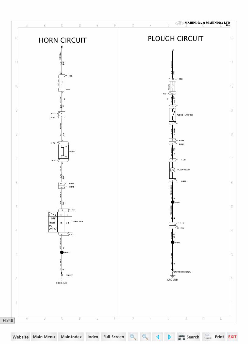
348H
Rise
PLOUGH CIRCUITHORN CIRCUIT
P
1
2
H-74
1
H-75
1
H-26
H-24
H-14219
H-142 9
H-14319
ECU -VE.
1
SP901
H-143 9
H-1202
SP900
SP030
H-1201
GND FOR CLUSTER.
1
H-1462
H-1182
H-1187
H-1467
H32 13
H3233
H32
7
H32
25
PLOUGH LAMP SW
F3/1
0A
GROUND
HORN
F4/1
0A
Combi SW 1
OFF
P T
3I H
PUSH TO ON" C"
GROUND
PLOUGH LAMPS
C-2
06 B/Y
0.75
SC
-520
BR
/B1.
0
EN
-401
G/W0.
75E
N-4
09V
/Y 0.75
SC
-401
G/W0.75
SC
-901
B
B0.75
SC
-409
V/Y
0.75
K
SC
-901
AB4.
0
FE
RH
-605
C
B1.0
SC
-900
AB
1.5
SC
-900
B4.0
FE
RH
-605
B
B1.5
FE
RH
-052
R/G
1.0
SC
-112
DR
/W4.0
SC
-112
A
R/W
4.0
https://www.truck-manuals.net/
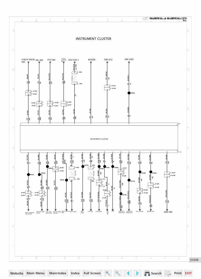
349H
Rise
CLUTCHOVERRIDEIND
BUZZER
OILPRESW
EMS ECU
PARKLAMP
PTO INDCHECK ENGININD
BATT SUPPLY NEUTRAL IND
EMS GNDIGN FUSE 2MIL IND
TURN LEFT FROM KKFM 4WD INDFUEL LEVEL
INDI GUAGEBATT CHARGINGINDICATION
HEAD LAMP HI INDI
AIR CLOG INDTURN RIGHTFROM KKFM
GNDSTOP LAMP
INSTRUMENT CLUSTER
H-142 8H-14211
H-14220
H-14324
SP101
H-142 24
SP901
H71 2 3 4 5 6
11
14
H-14320
H-143 8
H-1423
SP399
H-14215
H-1427
H-143
7
H-1433
SP329
H-14318
H-14315
SP44
H-143 11
SP560
SP209
H-14218
SP740
SP739
SP900
SP433
SP431
H-1183
H-1466
H-1186
H-1463
H-1373
H33
12
H32
18
H-13822
H32
38
H-1383
H-13718
H-1387
H-1377H-13722
H33
16
H3234
H61 2 3 4 5 6 7 8 9 10
11
12
13
14
15
16
H3214
H-138
18
SP438
F22
/5A
F40
/5A
F24
/5A
INSTRUMENT CLUSTER
SC
-438
BG
/B0.
75F
E R
H-0
51
G0.75
SC
-438
C
G/B
SC
-329
AW
/B0.
5
SC
-101
R0.
5S
C-8
07G
/R0.5
SC
-101
A
R0.5
SC
-313
SB
/B0.
5
SC
-732
G/R0.5
SC
-733
G/R
0.5
SC
-207
W/G
0.5
O
SC
-317
SB
/B
0.5
SC
-329
BW
/B0.5
SC
-560
G/W0.5
SC
-433
L/W0.5
SC
-431
B0.
75
BR
/B
SC
-208
R/L
0.5
Q
SC
-160
G/W
0.75
J
SC
-433
CL
/W
0.75
EN
-101
R0.5
SC
-136
GR
0.5
EN
-313
SB0.5
SC
-431
BR
/B
0.75
EN
-329
G/W0.5
COOLENT TEMP GUAGE
RPM SIG FROMEMS ECU
SC
-111
CY4.
0
SC
-112
D
R/W
4.0
FE
LH
-733
W/G
0.5
SC
-112
FR
/W4.0
IGN FUSE
SC
-560
A
G/W0.5
EN
-807
G/R
0.5
SC
-317
SB
/B
0.5
FE
LH
-732
O/G0.5
SC
-901
GB0.
5
SC
-410
G/Y
0.5
SC
-399
Y/B0.5
SC
-399
C
Y/B
SC
-44
V
SC
-44B
V0.5 S
C-2
09B
R/L
0.5
SC
-209
A
R/L
SC
-740
A
G/R
0.75
FE
LH
-739
A
R/W
SC
-900
EB
0.75
SC
-530
G/R0.5
SC
-739
G/R
0.75
SC
-900
B
FE
LH
-530
L/W0.5
FE
LH
-740
AB
R/R
0.75
EN
-399
B/Y0.5EN
-44
Y0.5
FE
RH
-027
AW
/Y0.
5
SC
-901
A
B4.0
EN
-410
G/Y
0.5
FE
LH
-739
B B
R/W
0.75
https://www.truck-manuals.net/
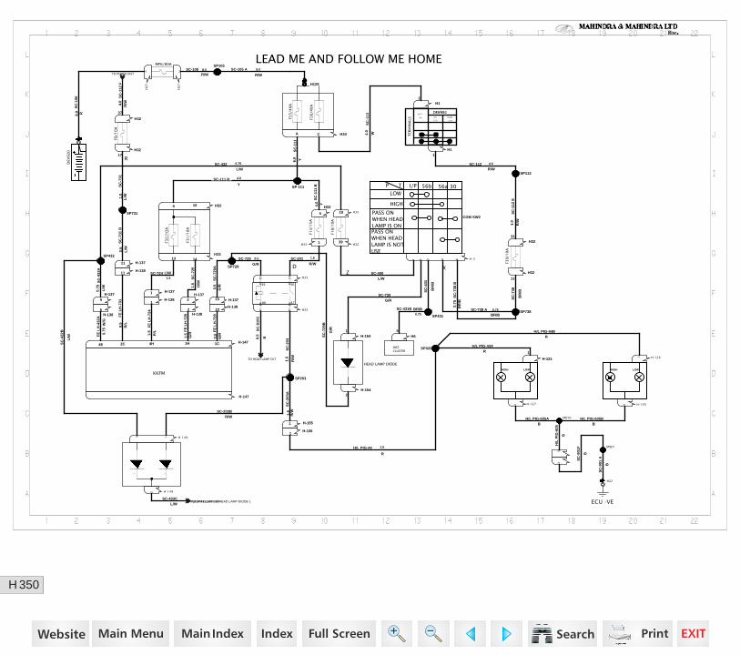
350H
Rise
FOR PARK LAMP CKT
TO POWER DIST
TO HEAD LAMP CKT
Z
LEAD ME AND FOLLOW ME HOME
H-1542
H-1541
H30A C
1
H2
7
1
H2
7
2
SP105
H129
1
SP729
H-1471C4H 1H4E 2C
H-147
SP203
H-1561
H-1551
SP432
H-1493 1
H-1492
SP731
H-1381
H329 10 H33
5
H-13823
H3217
H-1375
H-1385
H-1371 H-1372
H3313 14
H-1382
H-13711
H3219
H33R1
-86
R1
-87
H-13723
H3239
H-13811
H32
37
SP 111
H331
H33
R1
-30
R1
-85
H12
H11
SP112
SP738
H-1261
H-121
1
H-1273 H-1263
33
SP901
H22
H-34 65 31
SP431
SP020
SP010
H3231
H65
H32
11
F32
/1O
A
F31
/10
A
MF6/80A
F25
/40
A
F26
/40
A
DEV
920
DEV922
TER
MIN
ALS
BATT
(30) IGN
(T15)
CRANK
(T50)
POSITION
.
30
86 87
85
COM SW2
LOW
P T
I/P 56b 56a
HIGH
PASS ON WHEN HEAD LAMP IS ON
30
PASS ON WHEN HEAD LAMP IS NOT USE
KKFM
F39
/10
A
F13
/15
A
.
HIGH LOW HIGH LOW
ECU -VE
INSTCLUSTER
. .
F8/1
0A
F18
/10
A
HEAD LAMP DIODE
SC
-111
Y6.0
SC
-106
R8.0
SC-105R/W8.0 SC-105 A
R/W
8.0
SC-112R/W
4.0
SC
-112
ER
/W
1.0
SC-729 0.5
G/R
SC
-729
AG
/R0.5
SC
-729
B
G/RFE
LH
-729
G/R
0.5
FE
LH
-724
P/L
1.5 F
E L
H-7
25G
/R1.
5FE
LH
-432
A
W/G
0.75
FE
LH
-731
R/L
0.5
SC
-738
BR
/B
X
SC-738 ABR/B0.75
SC
-738
BB
R/B
0.75
SC-203BR/W
SC
-203
R/W
1.5
SC
-203
AR
/W1.5
H/L PIG-44BR
H/L PIG-44
R
1.5
H/L PIG-44AR
H/L PIG-605AB
H/L PIG-605BB
H/L
PIG
-605
B
SC
-901
F
B
SC
-901
A
B
SC-730G/R
SC
-431
BR
/B
SC-400L/W
SC-431B BR/B0.75
SC-432L/W
0.75
SC
-432
AL
/W
0.75
SC
-432
B
L/W
SC
-731
L/W1.
0
R
SC
-731
B
L/W0.5
SC-111 BY
4.0
SC
-111
B
Y4.0
D
SC-201R/W
1.5
SC-724 L/W1.5 S
C-7
25O
/W
1.5
SC
-910
C
B0.5
SC-433CL/W
PIN1/SP433,2/H-149/HEAD LAMP DIODE 1
SC
-112
FR
/W4.0
SC
-113
W4.0
https://www.truck-manuals.net/
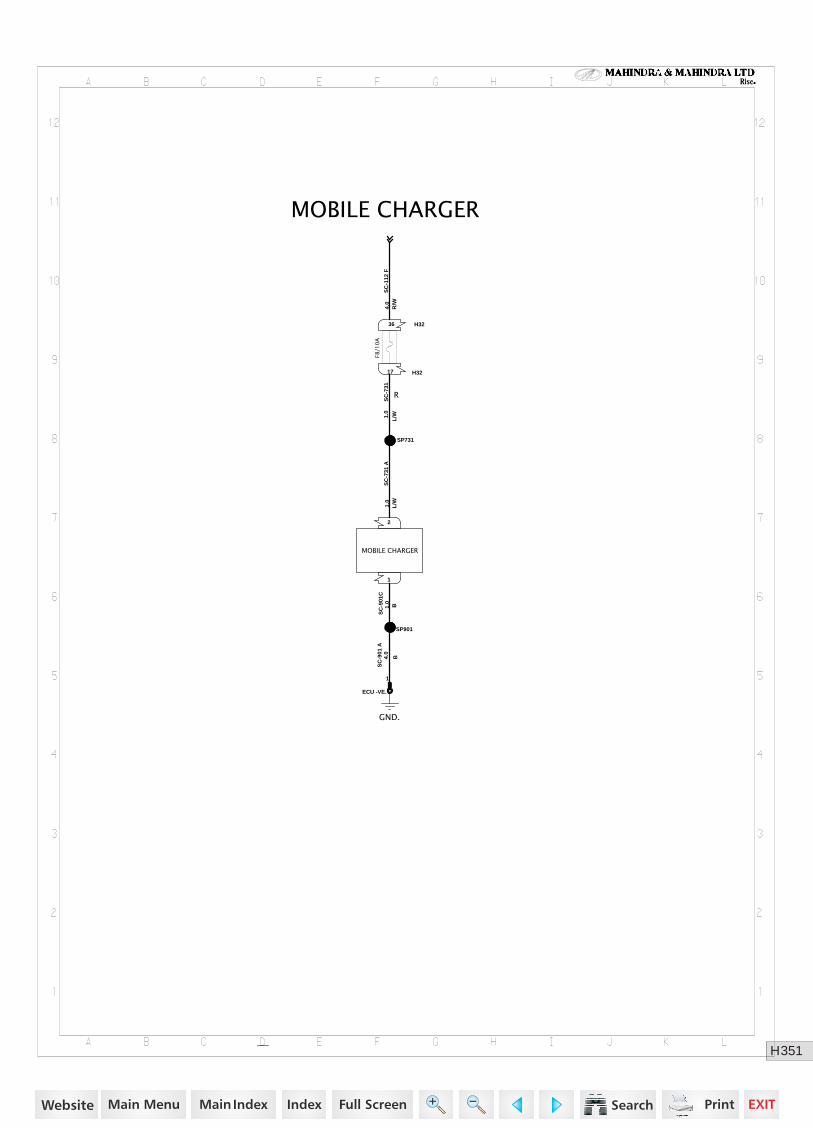
351H
Rise
MOBILE CHARGER
SP901
2
1
SP731
H3236
H3217
ECU -VE.
1
GND.
MOBILE CHARGER
F8/1
0A
SC
-901
C
B1.0
SC
-731
AL
/W1.0
SC
-731
L/W1.
0
R
SC
-112
FR
/W4.
0S
C-9
01 A
B4.0
https://www.truck-manuals.net/
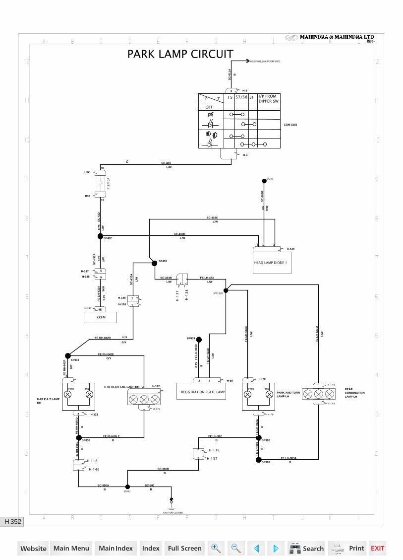
352H
Rise
PARK LAMP CIRCUIT
SP432
SP203
H-147 4E
H-149
1 23
SP903
H-1212
1H-703
SP433
SP433(1)
H-1482
H-1483
H-702
H-32
H-3
1
H-1223
H-1222
H-146 1
H-118 1
SP010
SP030
H-1467
H-1187
SP900
GND FOR CLUSTER.
1
SP902
SP903
H3219
H-138 5
H-1
38
6
H-13816
H-137 5
H3239
H-13716
H-1
37
6
H-682 1
H-03 P & T LAMP RH
PARK TRN
PARK AND TURN LAMP LH
PARK TRN REARCOMBINATIONLAMP LH
F18
/10
A
KKFM
REGISTRATION PLATE LAMP
HEAD LAMP DIODE 1
H-01 REAR TAIL LAMP RH
COM SW2
P T
I 5 57/58 3I
OFF
I/P FROM DIPPER SW
P
SC
-432
L/W0.75
SC
-432
A
L/W0.
75
FE
LH
-903
C
B0.75
FE
LH
-433
D
L/W
SC
-203
B
R/W0.5
FE
LH
-432
A
W/G
0.75
SC-433CL/W
FE
RH
-605
D
B
FE
RH
-042
F
G/Y
FE
LH
-433
B
L/W
SC-433BL/W
SC
-433
A
L/W
FE
LH
-433
A
L/W
FE LH-433L/W
FE LH-903AB
FE
LH
-902
G
B
Z SC-400L/W
FE RH-605 EB
FE RH-042EG/Y
FE RH-042D
G/Y
0.75
FE
RH
-605
C
B
SC-900AB
SC-900BB
SC-900B
FE
LH
-903
B
FE LH-902B
SC
-911
A
B
PIN1/SP911,2/H-3/COM SW2
SC-432BL/W
https://www.truck-manuals.net/
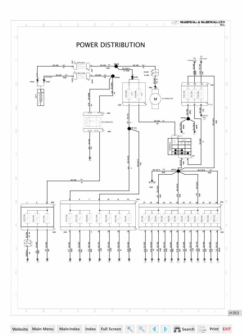
353H
Rise
COM SW1P.NO1
A c D E G H I JK L M O P Q T U
W
X Y
Z
AEAD
B F N R S V
AA
POWER DISTRIBUTION
H134
1
H135
1
H13
31 SP200
H28R2-86 R2-30
H28R2-85 R2-87
H13
32
SP738
H28567
H28
123
H84 1
H1291 H-136 1
H27
2
SP105
H-135 1H
271
17
17
SP112
H12
H1
1 3
H33 1 2 3 13 14 15 16
H335 6 7 9 10 11 12
SP 111
H32252627 333435 363738 282930
H32567 131415 161718 8910
H3231 20 19
H3211 40 39H30 A C
BA
TT
F39
/10
A
F21
/5A
F18
/10
A
MF7/30A
F4/1
0A
F34
/5A
F38
/10
A
F3/1
0A
F41
/5A
F37
/10
A
F22
/5A
F36
/15
A
F40
/5A
F42
/5A
F8/1
0A
F28
/10
A
F29
/10
A
F27
/10
A
F35
/5A
F26
/40
A
F25
/40
A
40
A
40
A.
TER
MIN
ALS
BATT
(30) IGN
(T15)
CRANK
(T50)
POSITION
MF6/80A
ALTERNATORM
ECU MAIN RLY
F30
/20
A
F12
/15
A
F32
/10
A
F31
/10
A
F24
/5A
F13
/15
A
F33
/10
A
SC-100R
8.0
SC
-111
B
Y4.0
SC
-111
C
Y4.
0
SC-105 AR/W8.0
B+
VE
SC-106R
8.0
ECU MAIN
SC-107
R/W
4.0 SC-200W4.0
SC
-200
A
W4.0
SC
-200
B
W0.75
SC
-330 W
1.0
SC-105
R/W
8.0
SC
-351
P/L
0.5
SC
-403
R/W2.5
SC
-402
R/L
2.5
EN
330
A
W
SC
-724
L/W
1.5
SC
-725
O/W
1.5
SC
-735
R0.5
SC
-202
R/O1.5
SC
-726
W/R
1.5
SC
-201
R/W
1.5
SC-103
R
4.0
SC
-738
BR
/B
SC
-111
Y6.0 SC-113
W
4.0
EN
-100 R
8.0
SC
-112
A
R/W
4.0
SC-112 B
R/W
4.0
SC
-112
D
R/W4.0
SC
-112
F
R/W4.
0
SC
-112
E
R/W
SC
-250
P
SC
-310
W0.
75
SC
-736
G/W
0.5
SC
-711
G/W
1.0
SC
-207
W/G
0.5
SC
-208
R/L
0.5
SC
-731
L/W1.0
SC
-707
0.5
R/G
SC
-326
G/R
0.5
SC
-205
V/Y
0.75
SC
-741
BR
/R
1.5
R1.30
4.0
R/W
SC-112 C
SC
-738
A
BR
/B
SC
-738
B
BR
/B
SC
-260
BR
/R0.
75
STARTING CKTPARK LAMPCKT
SC
-206
B/Y
0.75
SC
-409
V/Y
0.75
SC
-400
L/W
SC
-432
L/W0.75
SC
-160
G/W
0.75
SC
-112
R/W
https://www.truck-manuals.net/
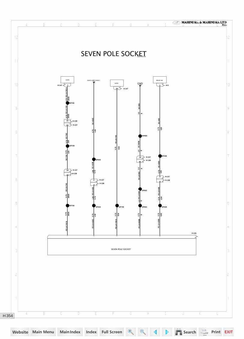
354H
Rise
KKFM HEAD LAMP DIODE1 BREAK SW
KKFM GND
SEVEN POLE SOCKET
SP740SP739 SP438
SP740
SP438
SP740
H-1472H
H-147 3H H-52
SP903
SP902
SP900
SP433
SP433
H-13716
H-1376
H-13824
H-1388
H-13724
H-1386
H-13816
H-1378
H-13824
H-13724
H-125
1 2 3 5 6
SEVEN POLE SOCKET
SC
-740
G/R
0.75
SC
-438
G/B
0.75
FE
LH
-438
B
G/W
0.75
FE
LH
-740
BB
R/R
0.75
FE
LH
-433
C0.
75L
/W
FE
LH
-739
DR
/W
0.75
FE
LH
-903
BB
0.75
FE
LH
-740
0.75
BR
/R
FE
LH
-739
R/W
0.75
FE
LH
-740
AB
R/R
0.75
FE
LH
-740
BR
/R0.
75
FE
LH
-903
B1.5
FE
LH
-902
B1.5
SC
-900
B
B1.5
SC
-433
BL
/W0.
75F
E L
H-4
33L
/W0.
75
FE
LH
-438
G/W
0.75
SC
-438
AG
/B0.
75
SC
-740
0.75
G/R
SC
-433
CL
/W0.
75
SC
-900
B4.0
GNDFOR CLUSTER
https://www.truck-manuals.net/
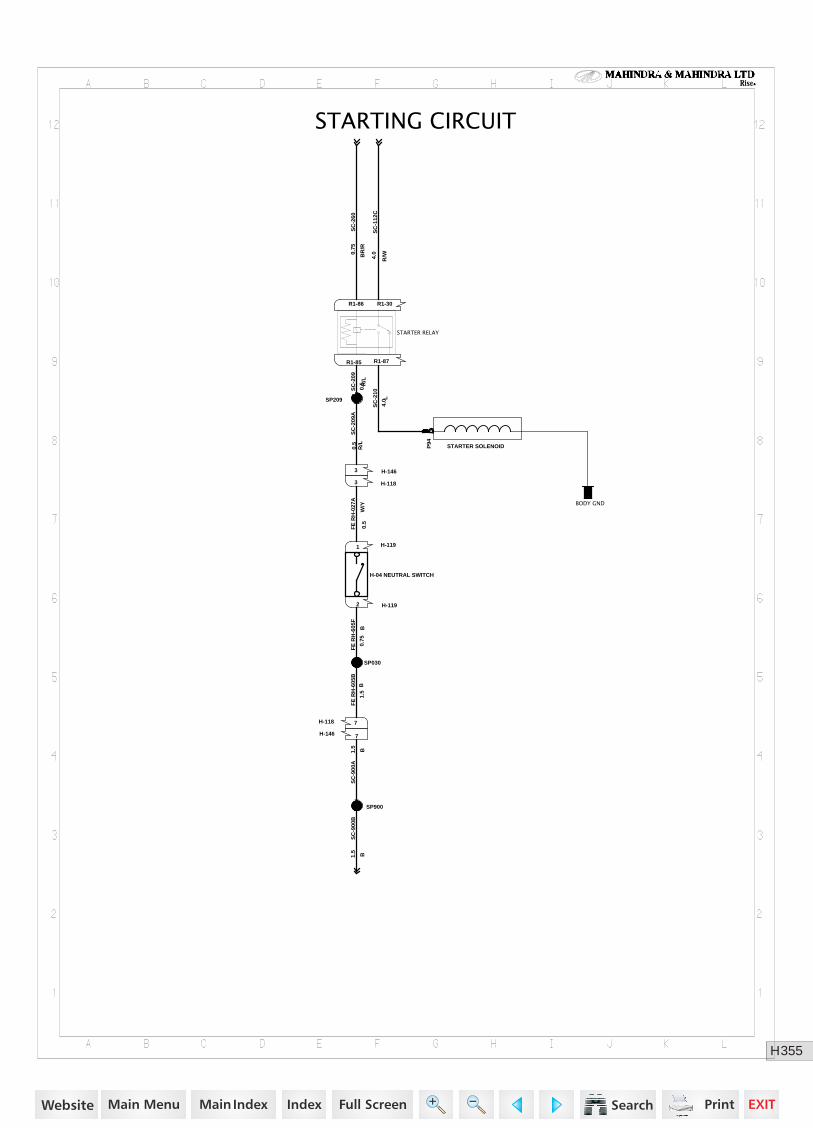
355H
Rise
STARTING CIRCUIT
P94
1
R1-30R1-86
SP209
H-1191
SP030
SP900
H-1192
H-1183
H-146 7
H-1463
H-118 7
R1-85 R1-87
BODY GND
STARTER RELAY
H-04 NEUTRAL SWITCH
STARTER SOLENOID
SC
-209
R/L
0.5
SC
-209
AR
/L0.
5F
E R
H-0
27A
W/Y
0.5
FE
RH
-605
F
B0.
75
FE
RH
-605
BB
1.5
SC
-900
A
B1.5
SC
-900
B
B1.5
SC
-260
BR
/R
0.75
SC
-112
C
R/W4.0
SC
-210
L4.
0
https://www.truck-manuals.net/
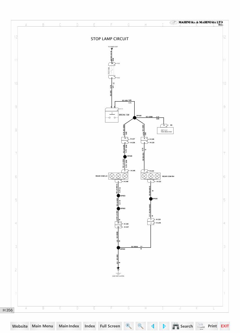
356H
Rise
STOP LAMP CIRCUIT
TO POWER DIST
INST CLU1PARK BREAK INDI
U
H-5
1 2
H-1466
H-1186
H-1224
SP438
H-1484
H-1483 H-1223
SP903
SP902
SP900
GND FOR CLUSTER.
1
SP030
H-1467
H-1187
H69
H3229
H-13816
H-1388
H329
H-1378
H-13716
SP438
F37
/10
A
BREAK SW
REAR COM RHREAR COM LH
SC
-205
V/Y
0.75
SC-438 G/B
0.75
SC-438B 0.75G/B
SC
-438
A
G/B
0.75
FE
RH
-051
G0.75
FE
LH
-438
G/W
0.75
FE
LH
-438
A
G/W
0.75
FE
LH
-903
A
B0.
75
FE
RH
-605
E
B
FE
LH
-903
B1.
5
FE
LH
-902
B
1.5
SC-900AB1.5
SC
-900
BB1.5
SC
-900
B4.0
FE
RH
-605
C
B1.0
SC
-112
BR
/W4.0
SC
-438
CG
/B0.
75
https://www.truck-manuals.net/
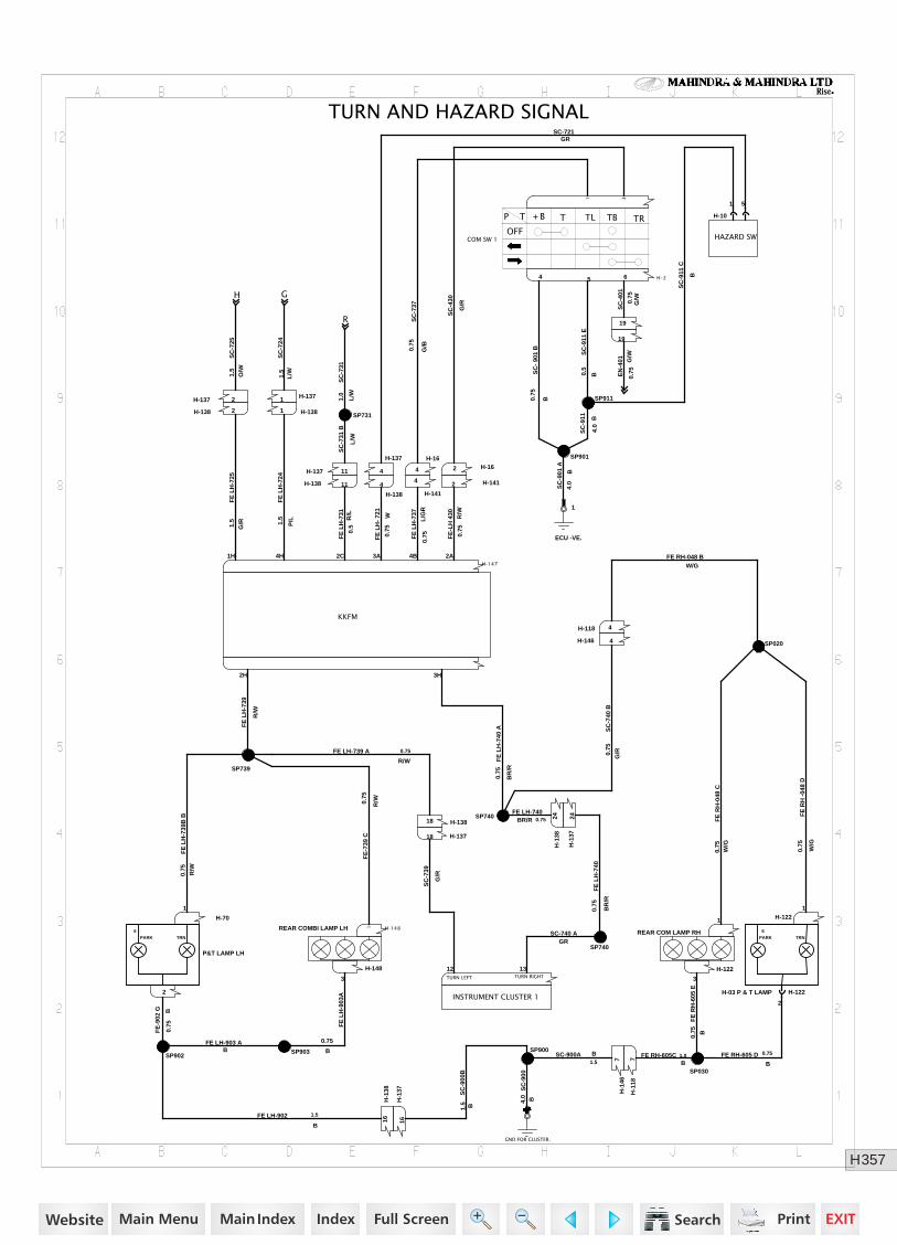
357H
Rise
GH
R
TURN AND HAZARD SIGNAL
H-141
4
H-16
4 H-162
H-1481
H-148
3
1 3
H -24 5 6
SP911
ECU -VE.
1
H-147
1H 4H 2C 3A 4B 2A
SP901
19
2H 3H
19
SP740
SP740
SP739
SP902
1
H-70
1
2
H-146 4
H-118 4
SP020
H-1221
H-10
1 5
H-122
3
SP900
GND FOR CLUSTER.
1
SP030
H-1
467
H-1
187
H-122
2
SP903
SP731H-1381
H-1
3816
H-1
3716
H-137 11
H-137 2
H-137
4
H-138 2
H-138
4
H-1371
H-1
3824
H-13818
H-138 11
H-1
3724
H-13718
12TURN LEFT
13TURN RIGHT
H-1412
HAZARD SW
REAR COMBI LAMP LH
KKFM
INSTRUMENT CLUSTER 1H-03 P & T LAMP
6
PARK TRN
P&T LAMP LH
6
PARK TRNREAR COM LAMP RH
COM SW 1OFF
P T
+ B T TL TB TR
FE LH-740BR/R 0.75
SC
-740
BG
/R0.75
FE
LH
-737
L/G
R0.
75
SC
-737
G/B
0.75
FE
-LH
430 R/W
0.75
SC
-430
G/R
FE
-739
C
R/W0.
75
0.75
B
FE
LH
-903
A
SC
- 90
1 B
B0.75
SC
-911
E
B0.5
SC
-401
G/W0.75
SC
-911
C
B
SC
-911 B
4.0
SC
-901
A
B4.
0
FE
LH
-725
G/R1.5
FE
LH
-724
P/L1.5
FE
LH
-731
R/L
0.5
FE
LH
- 72
1
W0.
75
FE
LH
-739
R/W
FE
LH
-740
BR
/R
0.75
SC-740 AGR
FE
LH
-739
B B
R/W
0.75
FE LH-739 A
R/W
0.75
FE
-902
G B0.
75
FE LH-903 AB
FE LH-902
B
1.5
FE
RH
-04
8 D
W/G
0.75
FE RH-048 BW/G
FE
RH
-048
CW
/G0.
75
SC-721GR
FE
RH
-605
E
B0.75
SC-900A B1.5
SC
-900
BB1.5
SC
-900
B4.0
FE RH-605 DB
0.75FE RH-605CB
1.0
SC
-731
B
L/W
SC
-739
G/R
SC
-725
O/W
1.5
SC
-724
L/W1.5
EN
-401 G
/W0.
75
SC
-731
L/W
1.0
FE
LH
-740
A
BR
/R
0.75
https://www.truck-manuals.net/


![Index [] · Index Chapter 1 – Introduction Chapter 2 – Mathematical modeling Chapter 3 – Results and Discussion . Introduction In the recent years, many studies (IEA International](https://img.pdfslide.us/doc/110x75/5e115e5bc52b4c198334b825/index-index-chapter-1-a-introduction-chapter-2-a-mathematical-modeling-chapter.jpg)