Embed Size (px)
Citation preview
Incremental Launching of Steel Truss Bridge
Rajiv SurekhaGeneral Manager,
Hindustan Construction Company Ltd
Nachiket TendulkarDeputy General Manager,
Hindustan Construction Company Ltd
209ARKEY CONFERENCE SERVICE CELL, PUNE
Managed by
AbstractFor launching superstructure, the spans are assembled in segments and tied together using temporary members behind abutment along the bridge alignment. Then the assembly of spans is pushed forward by jacks in steps. Depending on the design requirements, a temporary launching nose shall be added to reduce the erection stresses in the members. Subsequently, additional segments are added to the back of assembly as the launching progresses. At piers, special guides and bearings are placed to facilitate the push launching. The entire operation is repeated until the other abutment is reached. The force required for pushing keeps on increasing and therefore the abutment and the piers are to be checked for these forces. At the end of the launching operation, the temporary members connecting the spans are removed and the spans are placed on the permanent bearings.
2 0 1 7
1. Preamble
The present scenario demands timely completion of
works, rather speedy execution of challenging projects,
in difficult environmental and geographical conditions;
the method to execute the Project plays a major role right
from the inception stage itself. A systematic and scientific
analysis along with “Out of the Box” thinking towards
execution of a project will reduce both time and cost of the
project.
Each project will have its own challenges depending
upon either environmental conditions or geographical
conditions. Hence, the design of each project will vary
based on the prevailing conditions. To execute such
challenging projects, the customary or standard method
may either be Time/Cost consuming or may prove
unfeasible. Here, a specifically derived method to
execute the project will pave way to complete the project
within the timelines.
In this article we have demonstrated how the right
methodology has been implemented to complete the
project within the specified milestones.
1. Project Scope
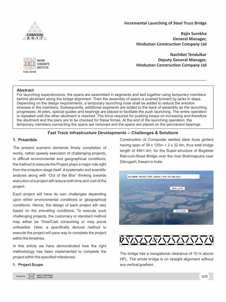
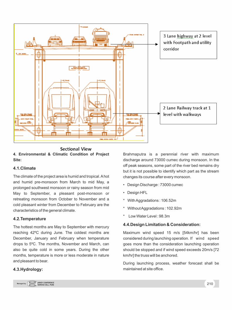
Construction of Composite welded steel truss girders
having span of 39 x 125m + 2 x 32.4m, thus total bridge
length of 4941.4m, for the Super-structure of Bogibeel
Rail-cum-Road Bridge over the river Brahmaputra near
Dibrugarh, Assam in India
The bridge has a navigational clearance of 10 m above
HFL. The whole bridge is on straight alignment without
any vertical gradient.
Fast Track Infrastructure Developments -- Challenges & Solutions
4. Environmental & Climatic Condition of Project
Site:
4.1. Climate
The climate of the project area is humid and tropical. A hot
and humid pre-monsoon from March to mid May, a
prolonged southwest monsoon or rainy season from mid
May to September, a pleasant post-monsoon or
retreating monsoon from October to November and a
cold pleasant winter from December to February are the
characteristics of the general climate.
4.2. Temperature
The hottest months are May to September with mercury
reaching 42ºC during June. The coldest months are
December, January and February when temperature
drops to 5ºC. The months, November and March, can
also be quite cold in some years. During the other
months, temperature is more or less moderate in nature
and pleasant to bear.
4.3. Hydrology:
Brahmaputra is a perennial river with maximum
discharge around 73000 cumec during monsoon. In the
off peak seasons, some part of the river bed remains dry
but it is not possible to identify which part as the stream
changes its course after every monsoon.
• Design Discharge : 73000 cumec
• Design HFL
* With Aggradations : 106.52m
* Without Aggradations : 102.92m
* Low Water Level : 98.3m
4.4. Design Limitation & Consideration:
Maximum wind speed 15 m/s [54km/hr] has been
considered during launching operation. If wind speed
goes more than the consideration launching operation
should be stopped and if wind speed exceeds 20m/s [72
km/hr] the truss will be anchored.
During launching process, weather forecast shall be
maintained at site office.
210ARKEY CONFERENCE SERVICE CELL, PUNE
Managed by
Before each launching process a weather forecast shall
be obtained and forecast for 5 more days starting from
the day of launching operation shall be reported.
5. Factors for Selection of Launching Method
5.1. River Hydraulics
Brahmaputra is a perennial river with maximum
discharge around 75000 cumec during monsoon. In the
off peak seasons, some part of the river bed remains dry
but it is not possible to identify which part as the stream
changes its course after every monsoon. It is therefore
not possible to formulate a method that avoids use of river
bed during construction.
5.2. Construction Speed
Such long bridges over a river like Brahmaputra take a
few years in construction. The aim is be to minimize the
construction time by an appropriate construction
scheme. The method should allow erection in all seasons
(except in monsoon or in high wind situations) and
involve minimum time between erections in adjacent
spans.
5.3. Number of Spans
A total of 41 spans have to be erected. Therefore,
construction from both ends of the bridge may be
considered to save time. The chosen erection method
must justify, cost wise, the number of spans to be erected.
5.4. Size and Self Weight
One normal span measures nearly 125m in length and
1700MT in weight. So, handling of such a massive
structure is of paramount importance. Simultaneously,
site work has also to be minimized. Assembly of
fabricated segments will influence the selection of
erection method.
5.5. Ground Conditions
Construction work carried out by providing temporary
supports from river bed is generally most simple, speedy
and economical. But given the river bed condition at this
site use of temporary supports is very uncertain. The
course of water flow, even in the off-peak seasons is very
unpredictable and it frequently changes with time.
5.6. Site Climate
The welding process for fabrication of the truss has to be
done in a controlled environment. The main trusses are
proposed to be fabricated in multiple units in workshop
and then brought to site. These units would be
assembled and connected at site in a controlled
environment before launching. No welding at site after
launching is allowed.
5.7. Construction Safety Requirements
The erection scheme adopted must provide a safe
operation for the construction personnel without
compromising on any safety aspect specified by the
governing body. It should also facilitate easy and regular
inspection and maintenance against possible corrosion
of the steel members.
5.8. Site Accessibility
Fabrication work would be primarily completed at
workshop. So, adequate transportation facility from
workshop to site would be required. Mobilization of
equipments for erection of truss, concreting etc. would
require the site to be easily accessible.
6. Methods of Superstructure Erection
Following are the commonly used erection methods
discussed herein for the selection of the most suited
method.
6.1. Cantilever Construction
By this method, first span of the bridge is assembled on
staging / falsework. After that, the second span is
erected, panel by panel, by cantilevering out from the first
span, using the first span as a counterweight.
Temporarily spans are made continuous for this purpose.
On the top chord, a crane is fixed to handle the panels.
Crane is moved forward after adding the panel. When the
cantilever reaches about 85% to 90% of the span,
temporary brackets are fixed to piers to receive and
support the cantilever tip. Length of these brackets could
be 10% to 15% of the span length. These steps are
repeated till all spans are completed.
Advantage: • Small weights are to be handled
Disadvantages:
211ARKEY CONFERENCE SERVICE CELL, PUNE
Managed by
• Time consuming due to bracket installations.
• All joints are to be done at site.
• Some members would require strengthening during
construction.
• Not suited for welded type of connections since field
welding is generally not recommended.
6.2. Erection using Floating Cranes or Pontoons
A full span is fabricated and assembled in the yard. Then
the assembled span is transported to a floating pontoon
through jetties. Pontoon carries it to the destination for
erection. The span is lifted and erected over the piers
using large capacity-floating cranes.
Advantages:
• The whole span is assembled in yard thus ensuring
good quality.
• Welding is done in controlled conditions and can be
checked thoroughly for quality before erection.
• Low erection time.
• No members require strengthening during
construction.
Disadvantages:
• Bigger weights are to be handled.
• Special equipments such as pontoons, floating cranes
are required.
• Appropriate river hydraulics required.
6.3. Incremental Launching / Push Launching
The spans are assembled in segments and tied together
using temporary members near abutment along the
bridge alignment. Then the assembly of spans is pushed
forward by jacks in steps. Depending on the design
requirements, a temporary launching nose can be added
to reduce the erection stresses in the members.
Subsequently, additional segments are added to the
back of assembly as the launching progresses. At piers,
special guides and bearings are placed to facilitate the
push launching. The entire operation is repeated until the
other abutment is reached. The force required for
pushing keeps increasing and therefore the abutment
and the piers are to be checked for these forces. At the
end of the launching operation, the temporary members
connecting the spans are removed and the spans are
placed on the permanent bearings.
Advantages:
• Assembly and pushing of launching truss to be
controlled at one location during the entire operation.
• Lower erection time.
Disadvantages:
• Bigger weights are to be handled.
• Temporary bearings and heavy jacks are required.
• Some truss members will require strengthening during
construction.
• Truss members are subjected to fluctuation of stresses
during the erection.
6.4. Steel Launching Truss
This erection method uses a specially fabricated
launching truss. Launching truss spans the length
between piers and has front nosing for auto launching.
The launching truss is placed over the first span of the
bridge on temporary supports. The fabricated span truss
is rolled over the launching truss from the yard using rails
and trolleys. When the span truss is over the launching
truss, specially designed frame, erected over the piers,
picks up the span truss using lifting tackles on the frames.
Now, the launching truss is relieved of the span truss
load. Launching Truss is then moved over to next span.
Span truss hung on the frames is launched into span over
bearings. Frames are removed and fixed on the other
piers. Deck slab is cast over the erected span. New span
truss is rolled over the erected span and the launching
truss. These the steps are repeated to complete the
second span erection and to move forward the launching
truss over to the next span.This is repeated till all spans
are erected.
Advantages:
• Number of spans will justify the initial investment on
212ARKEY CONFERENCE SERVICE CELL, PUNE
Managed by
launching truss
• Whole system is safe for all operations
• Finishing work on the erected span can be done as an
activity parallel to fabrication of span trusses
• No members require strengthening during
construction
• The whole span is assembled in the fabrication yard
ensuring good quality
• Welding is done in controlled conditions and can be
checked for quality before erection
• Low erection time
• Independent of river hydraulics
Disadvantages:
• Bigger weights are to be handled
• Special equipments are required
• Large deflection at cantilever tip of the launching truss.
After considering all above factors we have concluded
that incremental launching / Push launching would be the
best option for the launching of span truss.
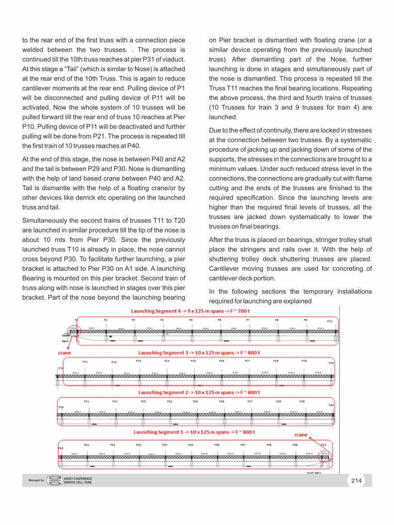
7. Incremental Launching
The superstructure is proposed to be launched by
“Incremental Launching” from the embankment on A1
side. Entire project standard spans, 39 nos of 125m, are
divided into 4 launching trains consisting of 3 trains of 10
spans and last train of 9 spans. This is done to keep the
launching force within limit of 900 ton. Required
Launching Force 1800.000 t x 10span x 5% = 900.0 t
The components of the truss like Nodes, Bottom chord,
Top chords, Vertical, diagonals etc are fabricated in a
custom built workshop. These fabricated units are
transported to Lay Down sheds (sheds 1and 2) wherein
the complete profile of each truss are marked on floor.
The components are assembled in Lay down condition to
make modules of about 30 m each. All welding, tests etc
are completed in these sheds. Each of these modules
(weighing about 110 to 135 T) are transported by two
gantries operating in tandem to the vertical assembly
yard (Sheds 3 and 4) wherein all these modules are
assembled to true line and level. The joints between the
two modules are welded here along with other
components like cross beam, bracings etc. The whole
truss is assembled on sledges of varying height to obtain
precamber.
These sledges will also facilitate longitudinal sliding of the
completed trusses in the yard. The sledges supporting
the truss will slide over the launching tracks which in turn
are supported by specially designed foundations.
Once the first truss (for span P39-P40) is completed, the
truss will be jacked up on another set of specially
prepared foundations (-temporary foundation) to verify
the camber (when the truss is supported on four end
supports). Once the camber checks are completed a
prefabricated Nose will be fixed to the front end of the
truss. The purpose of the Nose is to reduce the cantilever
bending moments and the reaction on bearings due to
cantilever.
During this process of fixing of nose, a launching bearing
will be mounted on -temporary foundation. For further
operations of launching, -temporary foundation of viaduct
will be used as support.
After the Nose erection is complete, the truss is pulled
forward with the help of a pulling device. This pulling
device is mounted on a Pier P1 and it will pull the truss
and the nose forward. As the truss moves forward, a
sequential jacking of the truss at temporary foundation is
done to control excessive reactions on the sledges.
Launching is continued till the nose takes reaction on the
launching bearing mounted on A1. In order to negate the
deflection of the nose tip due to cantilevering, the bottom
of the nose is profiled so that the nose lands freely on the
launching bearing in spite of cantilever deflection.
In order to satisfy the strength requirements during
launching process, the members of trusses (like bottom
chords, diagonals etc) are strengthened. For some
trusses, “A” struts are installed at specified locations to
minimize the stresses in the bottom chord.
Launching is continued further till the rear end of the first
truss reaches the foundation for camber checking. At this
time the second truss is moved forward and connected to
213ARKEY CONFERENCE SERVICE CELL, PUNE
Managed by
to the rear end of the first truss with a connection piece
welded between the two trusses. . The process is
continued till the 10th truss reaches at pier P31 of viaduct.
At this stage a “Tail” (which is similar to Nose) is attached
at the rear end of the 10th Truss. This is again to reduce
cantilever moments at the rear end. Pulling device of P1
will be disconnected and pulling device of P11 will be
activated. Now the whole system of 10 trusses will be
pulled forward till the rear end of truss 10 reaches at Pier
P10. Pulling device of P11 will be deactivated and further
pulling will be done from P21. The process is repeated till
the first train of 10 trusses reaches at P40.
At the end of this stage, the nose is between P40 and A2
and the tail is between P29 and P30. Nose is dismantling
with the help of land based crane between P40 and A2.
Tail is dismantle with the help of a floating crane/or by
other devices like derrick etc operating on the launched
truss and tail.
Simultaneously the second trains of trusses T11 to T20
are launched in similar procedure till the tip of the nose is
about 10 mts from Pier P30. Since the previously
launched truss T10 is already in place, the nose cannot
cross beyond P30. To facilitate further launching, a pier
bracket is attached to Pier P30 on A1 side. A launching
Bearing is mounted on this pier bracket. Second train of
truss along with nose is launched in stages over this pier
bracket. Part of the nose beyond the launching bearing
on Pier bracket is dismantled with floating crane (or a
similar device operating from the previously launched
truss). After dismantling part of the Nose, further
launching is done in stages and simultaneously part of
the nose is dismantled. This process is repeated till the
Truss T11 reaches the final bearing locations. Repeating
the above process, the third and fourth trains of trusses
(10 Trusses for train 3 and 9 trusses for train 4) are
launched.
Due to the effect of continuity, there are locked in stresses
at the connection between two trusses. By a systematic
procedure of jacking up and jacking down of some of the
supports, the stresses in the connections are brought to a
minimum values. Under such reduced stress level in the
connections, the connections are gradually cut with flame
cutting and the ends of the trusses are finished to the
required specification. Since the launching levels are
higher than the required final levels of trusses, all the
trusses are jacked down systematically to lower the
trusses on final bearings.
After the truss is placed on bearings, stringer trolley shall
place the stringers and rails over it. With the help of
shuttering trolley deck shuttering trusses are placed.
Cantilever moving trusses are used for concreting of
cantilever deck portion.
In the following sections the temporary installations
required for launching are explained
214ARKEY CONFERENCE SERVICE CELL, PUNE
Managed by
8. Installation of Enabling Structures for
Launching
To execute the launching process, following equipment /
machine and temporary steel structures are required
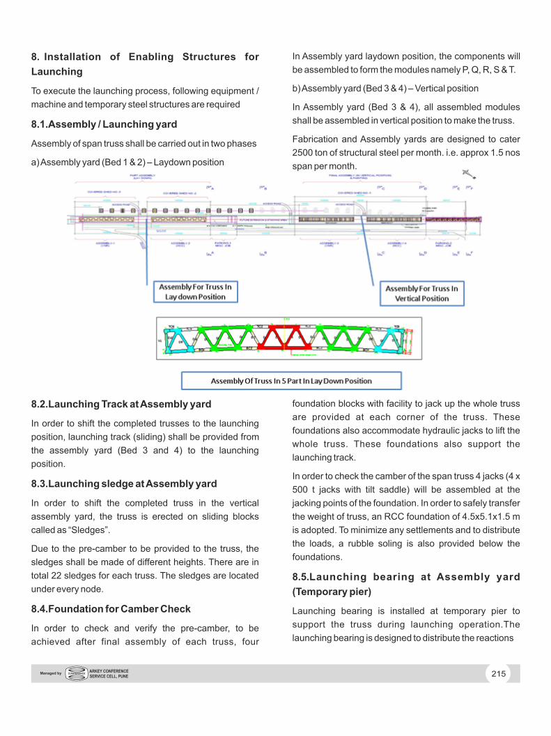
8.1. Assembly / Launching yard
Assembly of span truss shall be carried out in two phases
a) Assembly yard (Bed 1 & 2) – Laydown position
In Assembly yard laydown position, the components will
be assembled to form the modules namely P, Q, R, S & T.
b) Assembly yard (Bed 3 & 4) – Vertical position
In Assembly yard (Bed 3 & 4), all assembled modules
shall be assembled in vertical position to make the truss.
Fabrication and Assembly yards are designed to cater
2500 ton of structural steel per month. i.e. approx 1.5 nos
span per month.
8.2. Launching Track at Assembly yard
In order to shift the completed trusses to the launching
position, launching track (sliding) shall be provided from
the assembly yard (Bed 3 and 4) to the launching
position.
8.3. Launching sledge at Assembly yard
In order to shift the completed truss in the vertical
assembly yard, the truss is erected on sliding blocks
called as “Sledges”.
Due to the pre-camber to be provided to the truss, the
sledges shall be made of different heights. There are in
total 22 sledges for each truss. The sledges are located
under every node.
8.4. Foundation for Camber Check
In order to check and verify the pre-camber, to be
achieved after final assembly of each truss, four
foundation blocks with facility to jack up the whole truss
are provided at each corner of the truss. These
foundations also accommodate hydraulic jacks to lift the
whole truss. These foundations also support the
launching track.
In order to check the camber of the span truss 4 jacks (4 x
500 t jacks with tilt saddle) will be assembled at the
jacking points of the foundation. In order to safely transfer
the weight of truss, an RCC foundation of 4.5x5.1x1.5 m
is adopted. To minimize any settlements and to distribute
the loads, a rubble soling is also provided below the
foundations.
8.5. Launching bearing at Assembly yard
(Temporary pier)
Launching bearing is installed at temporary pier to
support the truss during launching operation.The
launching bearing is designed to distribute the reactions
215ARKEY CONFERENCE SERVICE CELL, PUNE
Managed by
uniformly of the bottom chord of truss uniformly. The
launching bearing at the temporary pier is also designed
for jacking of the bearings to control the reactions at
various stages of launching as defined in launching
operation.
8.6. A-Struts (For temp. strengthening of truss)
In order to reduce the stresses due to the local bending of
the bottom chord vertical temporary beams will be
arranged between the bottom chord and top joint of both
sides of the truss. Due to its geometry these members are
called “A” -struts. The “A” – struts are placed in the zones
of the maximum vertical forces due to launching.
8.7. Temporary Connection Truss
For the launching process it is necessary to connect the
single span truss girders to form a continuous beam. At
the connection point the last assembled truss (i.e. Tn-1)
will be connected to the already launched segment's
truss (i.e. Tn).
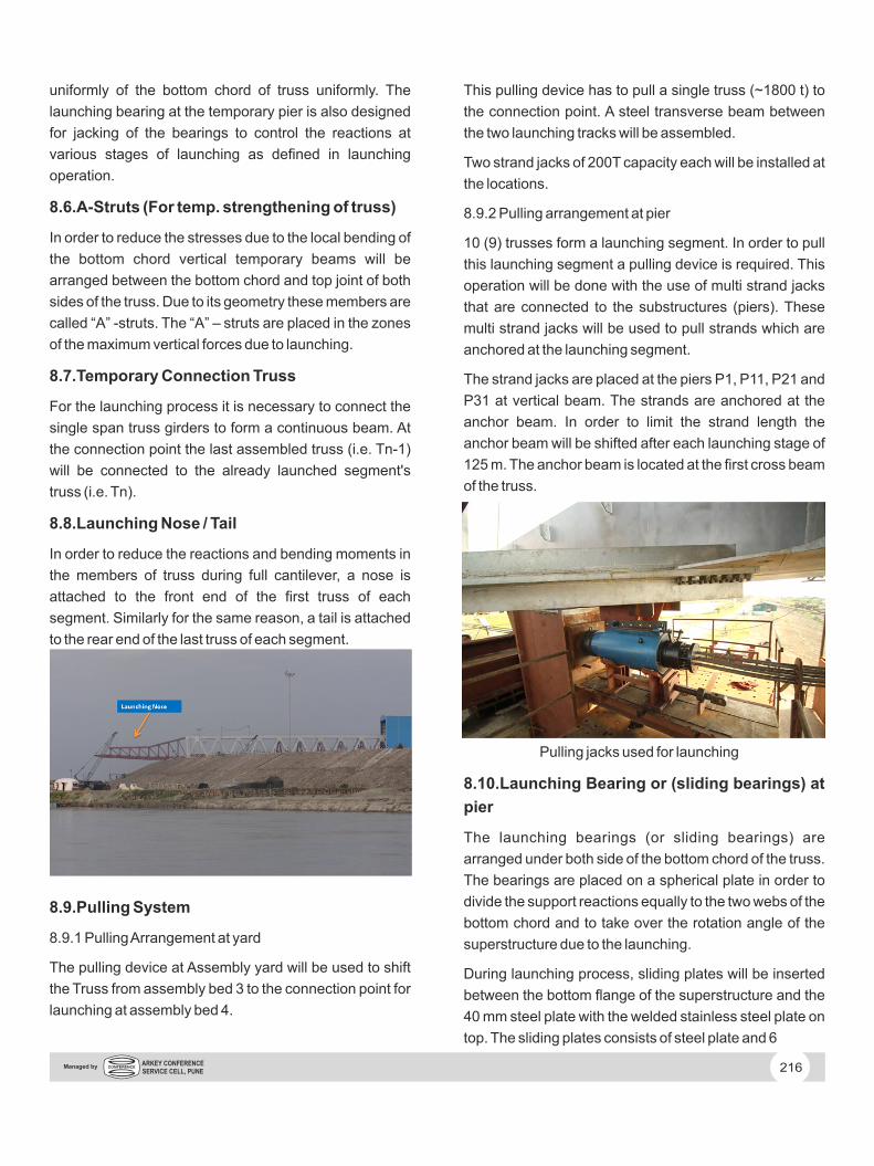
8.8. Launching Nose / Tail
In order to reduce the reactions and bending moments in
the members of truss during full cantilever, a nose is
attached to the front end of the first truss of each
segment. Similarly for the same reason, a tail is attached
to the rear end of the last truss of each segment.
8.9. Pulling System
8.9.1 Pulling Arrangement at yard
The pulling device at Assembly yard will be used to shift
the Truss from assembly bed 3 to the connection point for
launching at assembly bed 4.
This pulling device has to pull a single truss (~1800 t) to
the connection point. A steel transverse beam between
the two launching tracks will be assembled.
Two strand jacks of 200T capacity each will be installed at
the locations.
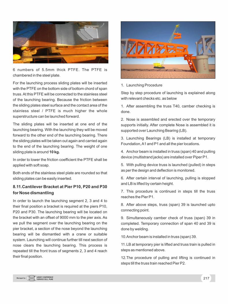
8.9.2 Pulling arrangement at pier
10 (9) trusses form a launching segment. In order to pull
this launching segment a pulling device is required. This
operation will be done with the use of multi strand jacks
that are connected to the substructures (piers). These
multi strand jacks will be used to pull strands which are
anchored at the launching segment.
The strand jacks are placed at the piers P1, P11, P21 and
P31 at vertical beam. The strands are anchored at the
anchor beam. In order to limit the strand length the
anchor beam will be shifted after each launching stage of
125 m. The anchor beam is located at the first cross beam
of the truss.
Pulling jacks used for launching
8.10. Launching Bearing or (sliding bearings) at
pier
The launching bearings (or sliding bearings) are
arranged under both side of the bottom chord of the truss.
The bearings are placed on a spherical plate in order to
divide the support reactions equally to the two webs of the
bottom chord and to take over the rotation angle of the
superstructure due to the launching.
During launching process, sliding plates will be inserted
between the bottom flange of the superstructure and the
40 mm steel plate with the welded stainless steel plate on
top. The sliding plates consists of steel plate and 6
216ARKEY CONFERENCE SERVICE CELL, PUNE
Managed by
6 numbers of 5.5mm thick PTFE. The PTFE is
chambered in the steel plate.
For the launching process sliding plates will be inserted
with the PTFE on the bottom side of bottom chord of span
truss. At this PTFE will be connected to the stainless steel
of the launching bearing. Because the friction between
the sliding plates steel surface and the contact area of the
stainless steel / PTFE is much higher the whole
superstructure can be launched forward.
The sliding plates will be inserted at one end of the
launching bearing. With the launching they will be moved
forward to the other end of the launching bearing. There
the sliding plates will be taken out again and carried again
to the end of the launching bearing. The weight of one
sliding plate is around 10 kg.
In order to lower the friction coefficient the PTFE shall be
applied with soft soap.
Both ends of the stainless steel plate are rounded so that
sliding plates can be easily inserted.
8.11. Cantilever Bracket at Pier P10, P20 and P30
for Nose dismantling
In order to launch the launching segment 2, 3 and 4 to
their final position a bracket is required at the piers P10,
P20 and P30. The launching bearing will be located on
the bracket with an offset of 9000 mm to the pier axis. As
we pull the segment over the launching bearing on the
pier bracket, a section of the nose beyond the launching
bearing will be dismantled with a crane or suitable
system. Launching will continue further till next section of
nose clears the launching bearing. This process is
repeated till the front truss of segments 2, 3 and 4 reach
their final position.
1. Launching Procedure
Step by step procedure of launching is explained along
with relevant checks etc. as below
1. After assembling the truss T40, camber checking is
done.
2. Nose is assembled and erected over the temporary
supports initially. After complete Nose is assembled it is
supported over Launching Bearing (LB).
3. Launching Bearings (LB) is installed at temporary
Foundation, A1 and P1 and all the pier locations.
4. Anchor beam is installed in truss (span) 40 and pulling
device (multistrand jacks) are installed over Piper P1.
5. With pulling device truss is launched (pulled) in steps
as per the design and deflection is monitored.
6. After certain interval of launching, pulling is stopped
and LB is lifted by certain height.
7. This procedure is continued in steps till the truss
reaches the Pier P1.
8. After above steps, truss (span) 39 is launched upto
connecting point.
9. Simultaneously camber check of truss (span) 39 in
completed. Temporary connection of span 40 and 39 is
done by welding.
10. Anchor beam is installed in truss (span) 39.
11. LB at temporary pier is lifted and truss train is pulled in
steps as mentioned above.
12. The procedure of pulling and lifting is continued in
steps till the truss train reached Pier P2.
217ARKEY CONFERENCE SERVICE CELL, PUNE
Managed by
13. The above steps are repeated till the truss train of 10
spans are launched completely.
10. Project Duration and present status
The contract envisages completion of project within
48months
Time cycle for
a. Fabrication and assembly of one truss = 20 days
b. Launching one span = 3 days
c. total days for one span launching = 23 days
for 34 spans as per contract, time required = 34 x 23 days
= 782 days
Considering 25 working days per months, time reqd = 32
months
Initial mobilisation and set up period = 9 months
Finishing Activites = 6 months
Total duration = 32 + 9 + 6 = 47 months
During the actual execution, the scope has increased by
additional 5 spans and weigth of the span has also
increased.
Accordingly Client has granted extension of time upto
June 2018.
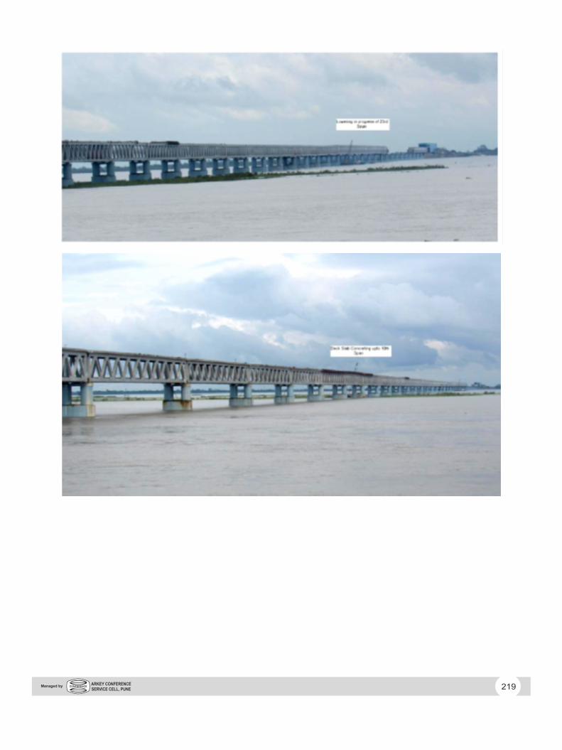
Presently 34 spans are Assembled and launched out of
39 spans.
218ARKEY CONFERENCE SERVICE CELL, PUNE
Managed by
219ARKEY CONFERENCE SERVICE CELL, PUNE
Managed by