Embed Size (px)
Citation preview
1 | Valve M A G A Z I N E
A ll facilities are under mountingpressure to maximize revenue
and improve efficiency. For manyapplications, installing intelligentvalve technology can lead to signifi-cant increases in productivity withminimal initial investment and shortpayback periods. This is especiallytrue in the oil and gas industry.In gas-lift applications, standard
manual valves typically used result ininefficiencies, while complicatedautomated systems can be difficult toinstall and expensive to maintain.However, installing integrated auto-matic flow control systems can boostoil production and reduce gas usagein such applications without the inef-ficiencies of manual valves or thecomplication and expense of auto-mated systems. Installation costs for these inte-
grated flow control systems can berealized in a matter of days and, over time, revenue can increase dramatically.
GAS LIFT INCREASES OILPRODUCTIONGas lift is a process by which gas, usu-ally natural gas, is injected through atubing-casing annulus. The process isnot new—it was used in wells in Penn-sylvania as early as 1864. In thoseearly days, the working fluid for thegas lift was compressed air. Later, nat-ural gas was used. While many mod-ern gas-lift applications use automat-ed gas injection, some continue to usemanual control of gas injection.For gas lift processes, a casing
pipe is drilled down into the oildeposit at depths of up to 15,000feet. The casing surrounds a second,tubing pipe, which creates a spacebetween the two pipes called theannulus. Pressurized natural gas,which in most applications is a
HOW TO INCREASE REVENUE INGAS-LIFT APPLICATIONS
Today’s industry needs to use every availablemeans to increase productivity and decreasecosts. For gas lift processes, a tool foraccomplishing that goal is to use an integratedflow control system.BY BRENT T. STEWART AND BRADFORD HAINES
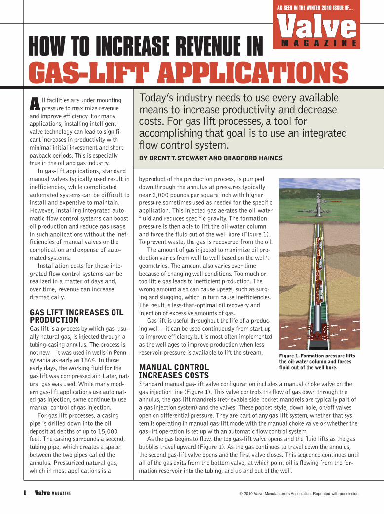
byproduct of the production process, is pumpeddown through the annulus at pressures typicallynear 2,000 pounds per square inch with higherpressure sometimes used as needed for the specificapplication. This injected gas aerates the oil-waterfluid and reduces specific gravity. The formationpressure is then able to lift the oil-water columnand force the fluid out of the well bore (Figure 1).To prevent waste, the gas is recovered from the oil.The amount of gas injected to maximize oil pro-
duction varies from well to well based on the well’sgeometries. The amount also varies over timebecause of changing well conditions. Too much ortoo little gas leads to inefficient production. Thewrong amount also can cause upsets, such as surg-ing and slugging, which in turn cause inefficiencies.The result is less-than-optimal oil recovery andinjection of excessive amounts of gas.Gas lift is useful throughout the life of a produc-
ing well—it can be used continuously from start-upto improve efficiency but is most often implementedas the well ages to improve production when lessreservoir pressure is available to lift the stream.
MANUAL CONTROL INCREASES COSTSStandard manual gas-lift valve configuration includes a manual choke valve on thegas injection line (Figure 1). This valve controls the flow of gas down through theannulus, the gas-lift mandrels (retrievable side-pocket mandrels are typically part ofa gas injection system) and the valves. These poppet-style, down-hole, on/off valvesopen on differential pressure. They are part of any gas-lift system, whether that sys-tem is operating in manual gas-lift mode with the manual choke valve or whether thegas-lift operation is set up with an automatic flow control system. As the gas begins to flow, the top gas-lift valve opens and the fluid lifts as the gas
bubbles travel upward (Figure 1). As the gas continues to travel down the annulus,the second gas-lift valve opens and the first valve closes. This sequence continues untilall of the gas exits from the bottom valve, at which point oil is flowing from the for-mation reservoir into the tubing, and up and out of the well.
Figure 1. Formation pressure liftsthe oil-water column and forcesfluid out of the well bore.
AS SEEN IN THE WINTER 2010 ISSUE OF...
© 2010 Valve Manufacturers Association. Reprinted with permission.
W i n t e r 2 0 1 0 | 2
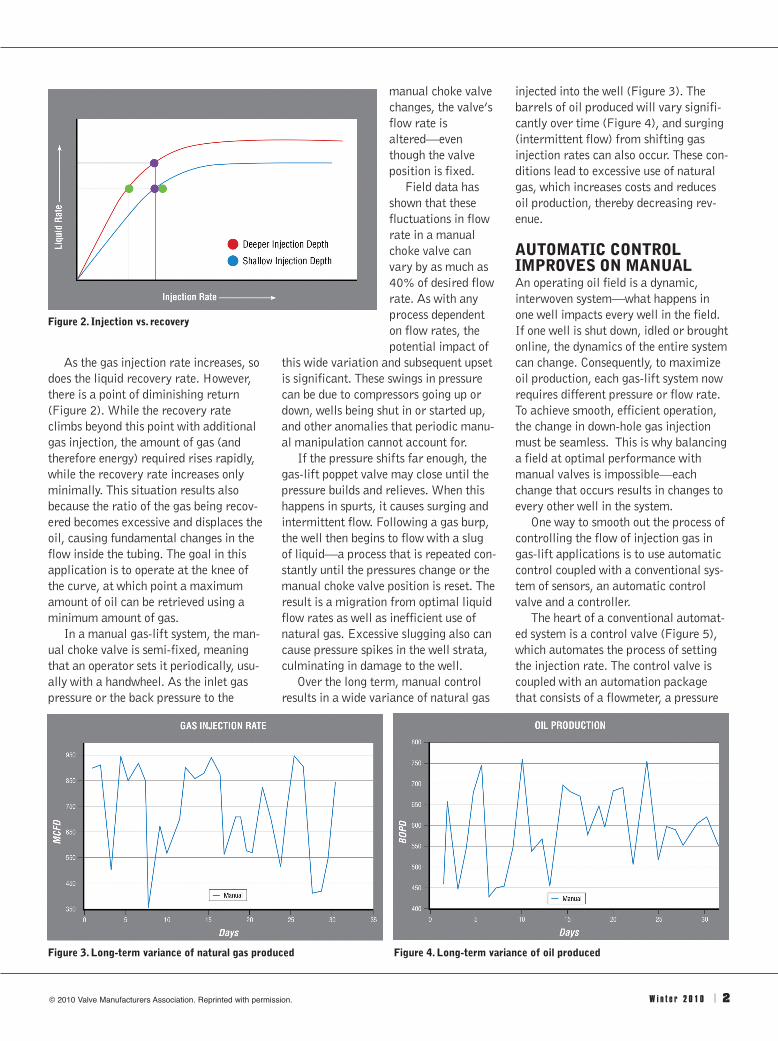
As the gas injection rate increases, sodoes the liquid recovery rate. However,there is a point of diminishing return(Figure 2). While the recovery rateclimbs beyond this point with additionalgas injection, the amount of gas (andtherefore energy) required rises rapidly,while the recovery rate increases onlyminimally. This situation results alsobecause the ratio of the gas being recov-ered becomes excessive and displaces theoil, causing fundamental changes in theflow inside the tubing. The goal in thisapplication is to operate at the knee ofthe curve, at which point a maximumamount of oil can be retrieved using aminimum amount of gas.In a manual gas-lift system, the man-
ual choke valve is semi-fixed, meaningthat an operator sets it periodically, usu-ally with a handwheel. As the inlet gaspressure or the back pressure to the
manual choke valvechanges, the valve’sflow rate isaltered—eventhough the valveposition is fixed. Field data has
shown that thesefluctuations in flowrate in a manualchoke valve canvary by as much as40% of desired flowrate. As with anyprocess dependenton flow rates, thepotential impact of
this wide variation and subsequent upsetis significant. These swings in pressurecan be due to compressors going up ordown, wells being shut in or started up,and other anomalies that periodic manu-al manipulation cannot account for. If the pressure shifts far enough, the
gas-lift poppet valve may close until thepressure builds and relieves. When thishappens in spurts, it causes surging andintermittent flow. Following a gas burp,the well then begins to flow with a slugof liquid—a process that is repeated con-stantly until the pressures change or themanual choke valve position is reset. Theresult is a migration from optimal liquidflow rates as well as inefficient use ofnatural gas. Excessive slugging also cancause pressure spikes in the well strata,culminating in damage to the well. Over the long term, manual control
results in a wide variance of natural gas
injected into the well (Figure 3). Thebarrels of oil produced will vary signifi-cantly over time (Figure 4), and surging(intermittent flow) from shifting gasinjection rates can also occur. These con-ditions lead to excessive use of naturalgas, which increases costs and reducesoil production, thereby decreasing rev-enue.
AUTOMATIC CONTROLIMPROVES ON MANUAL An operating oil field is a dynamic,interwoven system—what happens inone well impacts every well in the field.If one well is shut down, idled or broughtonline, the dynamics of the entire systemcan change. Consequently, to maximizeoil production, each gas-lift system nowrequires different pressure or flow rate.To achieve smooth, efficient operation,the change in down-hole gas injectionmust be seamless. This is why balancinga field at optimal performance withmanual valves is impossible—eachchange that occurs results in changes toevery other well in the system. One way to smooth out the process of
controlling the flow of injection gas ingas-lift applications is to use automaticcontrol coupled with a conventional sys-tem of sensors, an automatic controlvalve and a controller.The heart of a conventional automat-
ed system is a control valve (Figure 5),which automates the process of settingthe injection rate. The control valve iscoupled with an automation packagethat consists of a flowmeter, a pressure
Figure 2. Injection vs. recovery
Figure 3. Long-term variance of natural gas produced Figure 4. Long-term variance of oil produced
© 2010 Valve Manufacturers Association. Reprinted with permission.
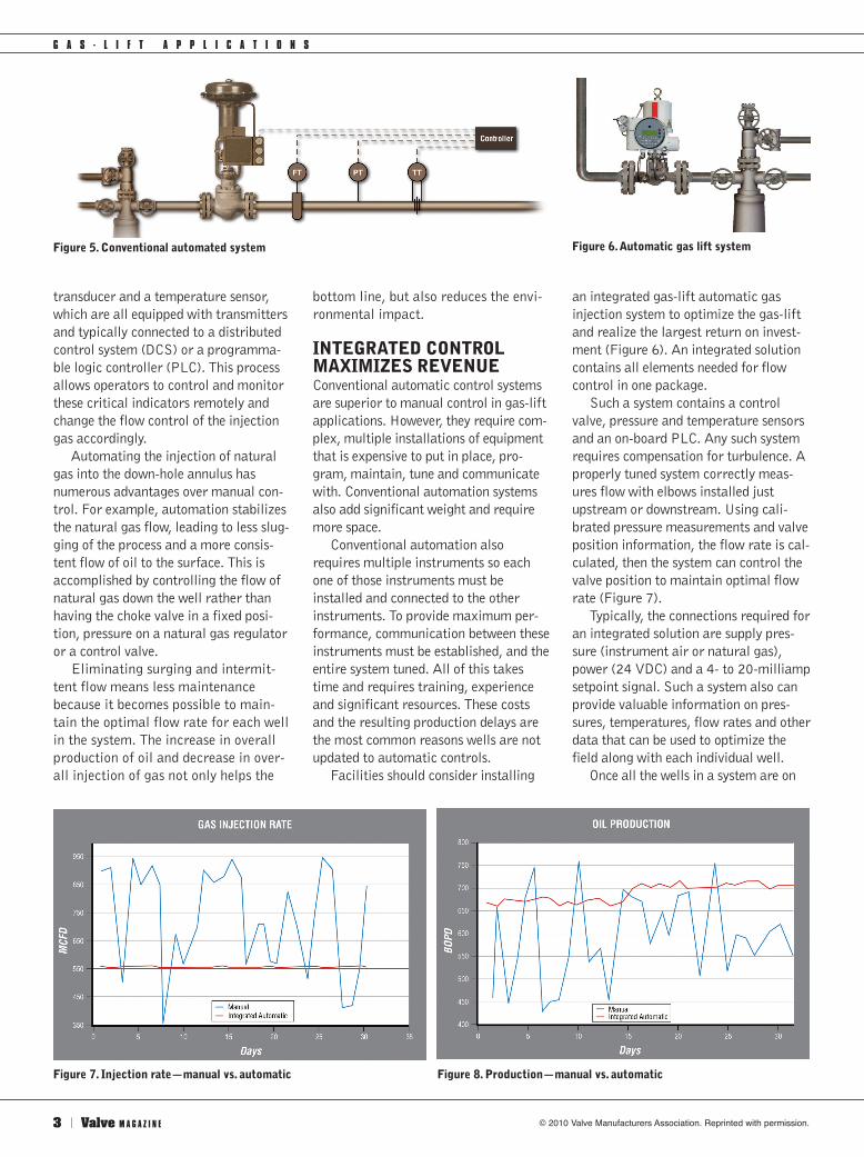
transducer and a temperature sensor,which are all equipped with transmittersand typically connected to a distributedcontrol system (DCS) or a programma-ble logic controller (PLC). This processallows operators to control and monitorthese critical indicators remotely andchange the flow control of the injectiongas accordingly.Automating the injection of natural
gas into the down-hole annulus hasnumerous advantages over manual con-trol. For example, automation stabilizesthe natural gas flow, leading to less slug-ging of the process and a more consis-tent flow of oil to the surface. This isaccomplished by controlling the flow ofnatural gas down the well rather thanhaving the choke valve in a fixed posi-tion, pressure on a natural gas regulatoror a control valve. Eliminating surging and intermit-
tent flow means less maintenancebecause it becomes possible to main-tain the optimal flow rate for each wellin the system. The increase in overallproduction of oil and decrease in over-all injection of gas not only helps the
bottom line, but also reduces the envi-ronmental impact.
INTEGRATED CONTROLMAXIMIZES REVENUEConventional automatic control systemsare superior to manual control in gas-liftapplications. However, they require com-plex, multiple installations of equipmentthat is expensive to put in place, pro-gram, maintain, tune and communicatewith. Conventional automation systemsalso add significant weight and requiremore space.Conventional automation also
requires multiple instruments so eachone of those instruments must beinstalled and connected to the otherinstruments. To provide maximum per-formance, communication between theseinstruments must be established, and theentire system tuned. All of this takestime and requires training, experienceand significant resources. These costsand the resulting production delays arethe most common reasons wells are notupdated to automatic controls.Facilities should consider installing
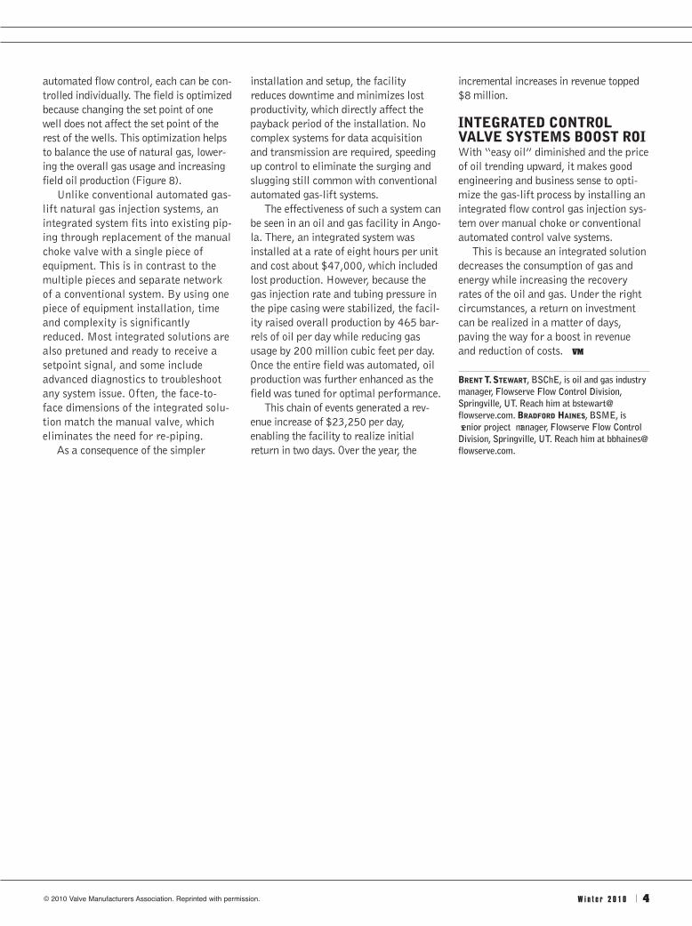
an integrated gas-lift automatic gasinjection system to optimize the gas-liftand realize the largest return on invest-ment (Figure 6). An integrated solutioncontains all elements needed for flowcontrol in one package. Such a system contains a control
valve, pressure and temperature sensorsand an on-board PLC. Any such systemrequires compensation for turbulence. Aproperly tuned system correctly meas-ures flow with elbows installed justupstream or downstream. Using cali-brated pressure measurements and valveposition information, the flow rate is cal-culated, then the system can control thevalve position to maintain optimal flowrate (Figure 7). Typically, the connections required for
an integrated solution are supply pres-sure (instrument air or natural gas),power (24 VDC) and a 4- to 20-milliampsetpoint signal. Such a system also canprovide valuable information on pres-sures, temperatures, flow rates and otherdata that can be used to optimize thefield along with each individual well. Once all the wells in a system are on
3 | Valve M A G A Z I N E
G A S - L I F T A P P L I C A T I O N S
Figure 5. Conventional automated system Figure 6. Automatic gas lift system
Figure 7. Injection rate—manual vs. automatic Figure 8. Production—manual vs. automatic
© 2010 Valve Manufacturers Association. Reprinted with permission.
automated flow control, each can be con-trolled individually. The field is optimizedbecause changing the set point of onewell does not affect the set point of therest of the wells. This optimization helpsto balance the use of natural gas, lower-ing the overall gas usage and increasingfield oil production (Figure 8).Unlike conventional automated gas-
lift natural gas injection systems, anintegrated system fits into existing pip-ing through replacement of the manualchoke valve with a single piece ofequipment. This is in contrast to themultiple pieces and separate networkof a conventional system. By using onepiece of equipment installation, timeand complexity is significantlyreduced. Most integrated solutions arealso pretuned and ready to receive asetpoint signal, and some includeadvanced diagnostics to troubleshootany system issue. Often, the face-to-face dimensions of the integrated solu-tion match the manual valve, whicheliminates the need for re-piping.As a consequence of the simpler
installation and setup, the facilityreduces downtime and minimizes lostproductivity, which directly affect thepayback period of the installation. Nocomplex systems for data acquisitionand transmission are required, speedingup control to eliminate the surging andslugging still common with conventionalautomated gas-lift systems. The effectiveness of such a system can
be seen in an oil and gas facility in Ango-la. There, an integrated system wasinstalled at a rate of eight hours per unitand cost about $47,000, which includedlost production. However, because thegas injection rate and tubing pressure inthe pipe casing were stabilized, the facil-ity raised overall production by 465 bar-rels of oil per day while reducing gasusage by 200 million cubic feet per day.Once the entire field was automated, oilproduction was further enhanced as thefield was tuned for optimal performance. This chain of events generated a rev-
enue increase of $23,250 per day,enabling the facility to realize initialreturn in two days. Over the year, the
incremental increases in revenue topped$8 million.
INTEGRATED CONTROLVALVE SYSTEMS BOOST ROIWith “easy oil” diminished and the priceof oil trending upward, it makes goodengineering and business sense to opti-mize the gas-lift process by installing anintegrated flow control gas injection sys-tem over manual choke or conventionalautomated control valve systems.This is because an integrated solution
decreases the consumption of gas andenergy while increasing the recoveryrates of the oil and gas. Under the rightcircumstances, a return on investmentcan be realized in a matter of days,paving the way for a boost in revenueand reduction of costs. VM
BRENTT. STEWART, BSChE, is oil and gas industrymanager, Flowserve Flow Control Division,Springville, UT. Reach him at [email protected]. BRADFORD HAINES, BSME, is senior project manager, Flowserve Flow ControlDivision, Springville, UT. Reach him at [email protected].
W i n t e r 2 0 1 0 | 4© 2010 Valve Manufacturers Association. Reprinted with permission.