Embed Size (px)
Citation preview
.INCLASS IT EDSECURITY CLASSIFICATION OF THIS PAGE (W"aen Dete Entered)
REPORT DOCUMENTATION PAGE REV)D INSTRUCTIONS"13EFORE COMPLETING FORM
1. REPORT NUMBER 2. GOVT ACCESSION NO. 3. RECIPIENT'S CATALOG NUMBER
4. TITLE (and Subtitle) 5. TYPE OF REPORT & PERIOC" COV.:RED
US ARMY TEST AND EVALUATION COMMANDTEST OPERATIONS PROCEDURE ____ri__nI
"i . "FRAGMENT PENETRATION TESTS OF ARMOR" 6. PERFORMING ORG, REPORT NUMBER
7• . AUTHOR(.) 8. CONTRACT OR GRANT NUMBER(e)
9. PERFORMING ORGANIZATION NAME AND ADDRESS 10. PROGRAM ELEMENT. PROJECT, TASK
AREA & WORK UNIT NUMEFRS
US ARMY ABERDEEN PROVING GROUND (STEAP-MT-M)ABERDEEN PROVING GROUND, MARYLAND 21005 DARCOM-R 310-611. CONTROLLING OFFICE NAME AND ADDRESS 12. REPORT DATE
'US ARMY TEST AND EVALUATION COMMAND (DRSTE-AD-M) __ Mr--' 1OS~~~13 -NUMB•"E'N" A •P G"ES- ABERDEEN PROVING GROUND, MARYLAND 21005 27
14. MONITORING AGENCY NAME & ADDRESS(If different from Controlling Office) 15. SECURITY CI.ASS. (of this report)
Unclassified
ISa. DECLASSIFICATION/DOWNGRADINGSCHEDULE
16. DISTRIBUTION STATEMENT (of ide Rleport)
Approved for public release; distribution unlimited.
17. DISTRIEUTION STATEMENT (of the abeiract entered in I3lock 20, It different from Report) " .
, 1 1~i VU
' I. SUPPLEMENTARY NOTES
0 19. KEY WORDS (Continue on reveree side It necessary and Identlify by block riumber)
Ammunition Fragments Vehicle, TrackedSArmor PenetrationC:. Fragmentation Projectile
* LU 20. ABST-rACT -C'antlr,. r Fever". sil Ft naco=wry end Identify by block numbhr)
Provides techniques for evaluating armor resistance to attack by HE projectilefragments. Includes static detonations of shell against armor plate and armored
C vehicles and firing tests using projectile fragments, fragment simulators, andsimulated fragments in a carister. Includes index of test data from static0} detonations of 105-mm and 155-mm projectile fragments against armor, fragmentcharacteristics tables, and technique for calculating fragment perforation prob-ability using Poisson distribution.
DD I JA14y- 1413 E0iTION OF I NOV 65 IS OBSOLU-TE
SECURITY CLASS!FICAt ION OF THIS PAGE (When Del. Entered)
0 83 03 18
US ARMY TEST AND EVALUATION COMMAND
TEST OPERATIONS PROCEDURE
DRSTE-RP- 702-101*Test Operations Procedure 2-2-722 15 March 1983
AD No.
FRAGMENT PENETRATION TESTS OF ARMORPage
Paragraph i. SCOPE. .............. .......................... 1
2. FACILITIES AND INSTRUMENTATION ......... ............. 23. REQUIRED TEST CONDITIONS ................ 34. TEST PROCEDURES. ................................. 34.1 Static Detonation of HE Projectiles Against Armor. . .. 3
Plates ("Yankee Stadium" Test)4.2 Gun Firing of Projectile Fragments ..... ........... 94.3 Gun Firing of Fragment Simulators ........ ............ 12
4.4 Gun Firing of Simulated Fragments in a Canister.. .... 15
4.5 Static Detonation of HE Projectiles Against........ 16Armored Vehicles
Appendix A. INDEX OF TEST DATA ON HE PROJECTILE FRAGMENTS, ...... A-iVERSUS ARMOR
B. FRAGMENT CHARACTERISTICS OF 105-MM AND 155-MM SHELL. . . B-I
C. CALCULATION OF THE PROBABILITY OF FRAGMENT PERFORA-. . . C-ITION USINC POISSON DISTRIBUTION
D. REFERENCES * . . . ........ . ........... D-1
1. SCOPE. This TOP describes the available techniques for testing armor forresistance to attack by projectile fragments. It includes the following: a)
static detonation of high-explosive (HE) projectiles against armor plates; b) gunfiring of projectile fragments; c) gun firing of fragment simulators; d) gunfiring of simulated fragments in a canister; and e) static detonation of HE
projectiles against armored vehicles. The basic methods applicable to each testmay be modified to suit specific test requirements.
While methods a) through d) are apDlicable to body armor a.s well as to vehicle
and aircraft armor, additional instructions on testing body armor with fragmentr;imilators (method c)) are contained in TOP 10-2-506.** 2Test techniques for
testing armor with projectiles are contained in TOP 2-2-710. -
*This TOP supersedes TOP 2-2-722 dated 25 October 1974.
**Footnote numbers correspond to reference numbers in Appendix D.
Approved for public release; distribution unlimited.
4.
TOP 2-2-722 15 March 1983
Because of the extensive use of HE projectiles in combat, armored vehicles of alltypes are required to provide a high degree of protection against shell frag-ments. Also, since fragmenting munitions have been responsible for a high per-centage of combat casualties, protection through body armor is a matter of con-tinuing concern. Thus, tests to determine the protection afforded by vehicle andbody armor against shell fragments have been given considerable attention.
Some indication of the ballistic protection afforded by armor against a fragmen-tation threat may be determined by laboratory and mathematical techniques basedupon established empirical relationships. It is necessary, however, to rely uponballistic testing, incorporating all of the factors important to a fragment/plateinteraction, for an accurate measure of the protection against a given threat,and for establishing baseline data.
Fragment penetration testing of armor is conducted to fulfill a variety ofrequirements such as:
a. Determining and romlparing the fragment penetration resistance of variousthicknesses and types of experimental materials.
b. Evaluating vehicle overhead, frontal, and flank protection based ondesign (or threat) requirements st'pulated in requirements documents.
c. Checking ballistic quality of production armor against minimum accept-able requirements (acceptance testing).
d. Determining the lethality of fragments that pass through the armor.
Many parameters are involved in fragment attack on armor, including:
a. Projectile parameters: caliber, velocity, angle of fall, direction fromtarget, distance from target, explosive type, type of casing, type of fuzing
b. Armor parameters: type, thickness, obliquity to attacking fragments,* mechanicalproperties, areal d nsity; body armor usually falls in the range of 1
to 20 kg/mr (0.2 to 4.0 lb/ft ), while ýehicle armor for fragment considerationfalls within tile range of 34 to 244 kg/m (7 to 50 lb/ft 2 ).
This TOP is an outgrowth of reference 9c, Appendix D, which contains additionaldetails oln fragment penetration tests of armor.2. FACILITIET S AND TNSTRPMENTAT!ON. Th . r. ind aed in t 4.,,•..-- 4d 1 Sub.
tests below. In addition to velocity-measuring equipment, the followingfacilities are required for gun firing of projectile fragments (see 4.2):
a. Smooth bore weapon. The caliber is determined by the size and weight ofthe fragment and velocity range to be explored. Calibers to 37-mm are employed.
b. Sabot. The sabot material is usually a type of plastic (linenbasephenolic, lexan, etc.), with the design, diameter, and length determined by theweight and shape of the projectile fragment. The fragment is held in position onthe sabot with paste or a nonhardening adhesive. Reference 9h describes firingwith a sabot. Teflon pushers are placed behind the sabots to act as obturators.
c. Sabot stripper or tipping device. The standard cal .22 or cal .30stripper screwed to the gun muzzle or the NRL (Naval Resc;rch Lab) tipper deviceis neecssary to separate the fragment from the sabot (see a Lso ref 9c, App. D).A sabot-discarding aid is also used. This is a steel deflector plate, . 6 -cm
2_.
TOP 2-2-722 15 March 1983
(1/ 4 -in) minimrum thickness, with a 2.5- to 3.2-cm-diameter (I- to 1-i/4-in) holealigned with the center of the gun bore, between the gun muzzle and the firstbreak screen.
d. Velocity break screen. A 10-by 15. 9 -cm (4-by 6-1/ 4 -in) (minimum)manifold paper with silver circuit grid, line space and width determined by frag-ment size, may be located both in front of and behind the target to initiate
* velocity-measuring instrumentation.
e. Yaw cards. These consist of double-weight, color-print photographicpaper located within 2.5 cm in front of the target to show the presented area offragments at impact.
f. Witness material. Building board, 1.3 cm (1/2 in) thick is used tocatch residual fragments which are recovered for analytical purposes.
g. Target holder. A rigid structure made of nonmetallic material is usedto hold the target in a fixed pcsition when the flash X-ray method is used.
Facilities for Subtest 4.4. The parallelepipeds, cubes, or other shaped simu-lated fragments in various weight ranges are packed in layers in a standardcanister or a specially desigaed sabot. In a typical test program, artificialfragments made from SAE 4140 steel are heat-treated to a hardness of Rockwell C30 + 1, placed in a modified 90-mm M366 canister projectile, and fired from a90-mm gun. Two 1.8--by 1.8-mr (6-by 6-ft) target plates are mounted side by side15 m (50 ft) from the muzzle. A 0.3-m space is left between thu plaLtes to clablethe base of the canister projectile to pass between without damaging the plates.Other details are contained in reference 9c (App. D).
3. REQUIRED TEST CONDITIONS. Armor plates are given a laboratory check if thereis a question about their mechanical properties. Other preliminary activitiesare described in the applicable sections below.
4. TEST PROCEDURES.
4.1 Static Detonation of HE Projectiles Against Armor Plates ("Yankee Stadium"Test-).
4.1.1 hCjective. The objective is to determine the resistance to penetration ofvarious armor materials, thicknesses, and composites against actual fragmentingmunitions, and to use the data to build up a data bank. This procedure dealswith flat plates only; similar procedures may be used, however, on the few occa-sions when fabricated assemblies are tested.
NOTE: An index to the data bank of HE projectile detonations that have been con--ductod against armor is included in Appendix A.
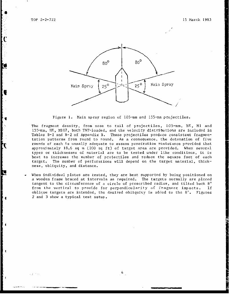
4.1.2 Method. Position the plates to be tested in a circular array at aspecified distance and orientation from a given HE projectile to represent agiven attack condition. Most often, you should mount the projectile verticallyso that the targets will receive the main spray of the bursting shell. The mainspray, characterized by high-velocity and high fragment spatial density, consistsof those fragments that fly off to the side of the projectile over theapproximate range of 80' to 105' from the nose of the projectile (,:ee Figure 1).
3
0
TOP 2-2-722 15 March 1983
VaFmin Spray 2Lz? 250 Main Spray
, /
Figure 1. Main spray region of 105-mm and 155-mm projectiles.
The fragment density, from nose to tail of projectiles, 105-mm, HE, M14 and"155-mm, RE, M107, both TNT-loaded, and the velocity distributions are included inTables B-i and B-2 of Appendix B. These projectiles produce consistent fragmen-tation natterns from round to round. As a consequence, the detonation of fiverounds of each is usually adequate to assess penetration resistance provided thatapproximately 18.6 sq m (200 sq ft) of target area are provided. When severaltypes or thicknesses of material are to be tested under like conditions, it isbest to increase the number of projectiles and reduce the square feet of eachtarget. The number of perforations will depend on the target material, thick-ness, obliquity, and distance.
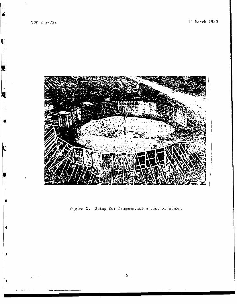
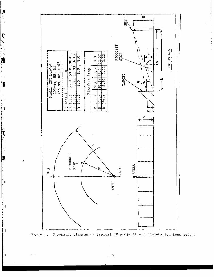
When individual plates are tested, they are best supported by being positioned ona wooden frame braced at intervals as required. The targets normally are placedtangent to the circumference of a circle of prescribed radius, and tilted back 80from the vertical to provide for perpendicularity of fragment impacts. Ifoblique targets are intended, the desired obliquity is added to the 80. Figures2 and 3 show a typical test setup.
41, 4 -_ . .
0TOP 2-2-722 15 March 1983
4Al
Ins
C Figure 2. Setup for fragmentation test of armor.
\,
0 PL4
rrj
0'n0 C)Lt!
0 OO • 0 N)
~rd
H~. C04J 0
E4fl
r I Qr CrN
t-C-
e4J 4-J 4-1.~
>I
OK-A
U00
Figure 3. Schematic diagram of typical HE projectile fragmentation test setup.
TOP 2-2-722 15 March 1983
Position the projectiles vertically on a pedestal at the center of this circle ata height that will cause the densest part of the main spray (983 angle from nose)to strike the vertical center of the targets. Unless special test conditions arespecified, mount the projectile nose up. Check the vertical alignment in twodirections 900 apart using a plumb line. Since a deviation of 10 displaces themain spray 0.5 m (1-1/2 ft) at a distance of 27 m (90 ft), take care to make theprojectile absolutely plumb.
The fragmenting projectiles are generally provided with modified fuzes to allowready acceptance of electrical firing detonators. After positioning the projec-tile, insert the firing device, and detonate from some remote and protected area.It is important that the modification of the fuze does not modify the fragmenta--tion pattern of the projectile.
To assure proper orientation of the projectile and to separate results into an-gular zones, the targets are provided with horizontal lines, one through the cen-ter and the others spaced 10 apart, centered on the projectile. Fragmentpenetrations from individual projectile bursts are identified by painting hitswith distinguishing colors.
4.1.3 Data Required. Record the following test data:
a. Projectile - full nomenclature, including type of fuzeb. Distance from center of arena to the targetc. Target obliquity in degreesd. Fragment spray zone uoveLed by Largets, in degrees (e.g., 95.6' to
100.40 from nose)e. Target material, thickness and alloy temper, mechanical properties, and
military specification as appropriate, and manufacturer's namef. Target area (including length and width of individual plates)g. Number of fragment perforations for each round fired, their dimensions
and locations
h. Number and definition of significant hits, and their locations withrespect to 1V zones
4.1.4 Analytical Plan.
a. To analyze the fragmentation effects on the target plates, you must es-tablish criteria for hits and perforations. The following definitions apply:
(1) Significant hit (sometimes called valid hit or effective hit) - anypenetration equal to or greater than 0.3 cm (1/8 in) deep for steel targets andequal to or greater than 1 cm (3/8 in) deep for aluminum targets. (Other defini-tions, such as the ability to perforate a 16-gage mild steel plate placed infront of the target, have been used in the past but are discouraged.)
(2) Periouation - any penetration wherein some target material is dis-placed from the rear of the plate or the fragment passes completely through theplate. (This definition closely resembles the definition of a complete penetra-tion under the "protection" criterion (TOP 2-2-710), but for this application, athin-gage aluminum witness material is not really necessary.)
b. Determine the number of significant hits per square meter and the per-forations per square meter for each round. (Separation into 10 zones is usually
-,, Yr. 7.
TOP 2-2-722 15 March 1983
desirable.) Additionally, calculate the percent protection for each round, andfor the total of all rounds, using the following formula:
Percent protection = 100 1 - siificant hits
c. Also determine the probability of perforation (for a given zone of thespray - see 4.1.3d above), using the Poisson distribution. In this case, thenumber of hits (which is really arbitrarily defined) is not considered; only theperforations from each round on a given area at a given distance are considered.If a confidence coefficient is not given, it is assumed to be .95. Make the fol-lowing determinations, as a minimum, following testing under each condition, withplates positioned X meters from the projectile.
Probability of no perforations per round per sq mat distance X.
Probability of 2 or more perforations per round persq m at distance X.
Probability of perforations per roundsper sq m at distance X (as specified in directive).
The details for making these determinations are contained in Appendix C.
d. In each case when plates are at an 80 tilt, the actual angle ofobliquity of the plate with respect to incoming fragments may be in the range of0' to 6' which includes the effect of gravity on the trajectory of fragments.For all practical purposes, however, this is considered to be normal attack con-dition, i.e., 00 obliquity.
e. The only fragments of consequence against vehicular armor are those thatare heavy and originate with high velocities. Aside from negligible exceptions,these fragments are found in the 800 to 1050 main spray. Important in thisregard is the fact that the velocities of large fragments do not decrease withdistance as rapidly as velocities of small fragments, as shown in Table B-3,Appendix B. If, for some reason, there is a requirement to interpret results interms of other angular zones in addition to those covered by the targets, theperforations to be expected in the various zones of the main spray will be inproportion to the number (after data smoothing) of fragments over 400 grains from105-mm shell, and over 750 grains from 155-mm shell (Tables B-i and B-2, App. B).
f. To interpret data from 0' obliquity attack in terms of attacks at otherobliquities, it is desirable to use a computer model such as that developed byArmy Materiel Systems Analysis Agency (AMSAA). A simplification, which is lessaccurate, is to assume that the plate resistance will be constant for the samestraight line distance through the plate - the so-called cosine relationshipwherein, for example, 5.0 cm at 00 is considered equal to 2.5 cm at 600, or:
Thickness at 0 = (Thickness at 00) (Cos 0).
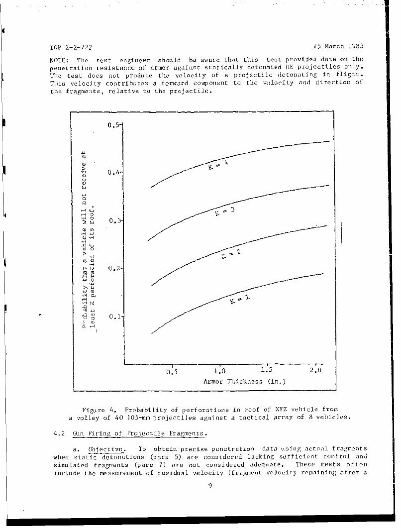
The AMSAA computer model, using the data from tests such as these, can developcurves such as those of Figure 4.
8
TOP 2-2-722 15 March 1983
NOTE: The test engineer should be aware that this test provides data on the
penetration resistance of armor against statically detonated RE projectiles only.
The test does not produce the velocity of a projectile detonating in flight.
This velocity contributes a forward coiqeonent to the velocity and direction ofthe fragments, relative to the projectile.
0.5-
>"0.4-
Qý4
0
• r-.I 01J 0.'
-~44
.H
-W 4J 0,2-
4.4
'H 04
-o.1
L cI-qI-.
0.5 1.0 1.5 2.0
Armor Thickness (in.)
Figure 4. Probability of perforations in roof of XYZ vehicle froma volley of 40 105-mm projectiles against a tactical array of 8 vehicles.
4.2 Gun Firing of Projectile Fragments.
a. Objective. To obtain precise penetration data using actual fragmentswhen static detonations (para 5) are considered lacking sufficient control andsimulated fragments (para 7) are not considered adequate. These tests ofteninclude the measurement of residual velocity (fragment velocity remaining after a
9
TOP 2-2-722 15 March 1983
compiete penetration of the armor) to assess the lethality of the fragments thatpenetiate, particularly in connection with body armor. This section dealsprimarily with vehicular armor. For tests of body armor, see TOP 10-2-506.
b. Method. In this test, use actual shell fragments recovered from staticdetonations of HE projectiles. (For tests of vehicular armor, fragments from105-mm and 155-mm shell are frequently used. For tests of body armor, fragmentsfrom mortar shell and foreign ammunition are more appropriate.) Use a softrecovery technique, generally employing wallboard which will not damage the frag-ments. TOP 4-2-813§ describes a method for recovering a small portion of themain spray. To recover all of the main spray would require that wallboard bestacked all around the sides of the projectile at an appropriate standoff.Mount, in a sabot, each recovered fragment to be fired. If residual velocity(behind the target) is to be obtained, the technique used to measure residualvelocity is also used to measure velocity before impact.
4.2.1 Velocity Measurement Techniques. The two methods that may be employed tomeasure fragment velocities are (a) the flash X-ray method which should be usedwhen the target may break up, such as during testing of metallic or hard-facedcomposites; and (b) the chronograph, break screen (or lumiline screen) methodwhich is generally used when nonmetallic or fabric-type targets are to be tested.The break screens are used to trigger the X-ray tubes and chronograph. FlashX-ray (radiographic) techniques are generally covered in TOP 4-2-8254, withspecific information on velocity measurements in TOP 2-2-710. Chronographictechniques are described in TOP 4-2-805.5 The setups used in testing body armor(which are also applicable for vehicular armor) are shownr in TOP 10-2-506.Velocity measurements of fragments require that special drag coefficients be ob-tained from appropriate sources. Gun-to-target distances will vary. They may beas little as 132 cm (52 in) for very small fragments fired at body armor, al-though 3 to 4.9 m (10 to 16 ft) is more common. Vehicular armor may require dis-tances as great as 12 m (40 ft).
4.2.2 Determining a VS0 Ballistic Limit. Select fragments to be fired that areas close to the prescribed weight as possible, and choose fragments with charac-teristic shapes. For vehicular armor, this is preferably within (+) 5%, but notbeyond (+) 10%; for body armor where fragments of 2 to 70 grains may be used,this is preferably (+) 2% to 3% but not beyond (+) 5%. The range of fragmentweights rhat must realistically be tolerated within a given weight category is afactor that tends to promote a large zone of mixed results during the determina-tion of a V50 ballistic limit (see TOP 2-2-710). An even more significant factorin this regard is that the wide variety of shapes, hardness patterns, and impactorientations that are possible with randomly selected fragments within the sameweight category will result in great variations in the penetrating efficiency ofthe different fragments. Thus, within the constraints of a typical test program,the V50 ballistic limit determination can, at best, only be considered a fair ap-proximation. The wide variations in the attacking missile cause a considerableamount of data scatter. (This is the primary reason that the methodologies ofparagraphs 4.3 and 4.4 are often preferred to shooting actual fragments.)
To determine the V50 ballistic limits, the up-and-dnvwn firing technique is usual-ly employed (TOP 2-2-710), with the ballistic limit being based, when practical,upon the average of 10 striking velocities: the five highest partial penetrationsand the five lowest complete penetrations occurring within a velocity spread of46 m/sec (150 ft/sec). Six or eight striking velocities have also been used as a
"10
TOP 2-2-722 15 March 1983
base but are less desirable. A complete penetration is defined by the"protection" criterion; that is, an impact that results in either a portion ofthe plate or fragment moving behind the plate with sufficient energy to perforatea witness sheet of 0.051 cm (0.020-in) aluminum. Fragment velocities are con-trolled as usual by varying the weight of propellant. In doing so, however, thevarying weights of the combined weight of sabot plus fragment must be considered.A suitable approach when testing vehicular armor is to fire one of the medium-weight fragments and use the following empirically derived relationship to detcr-mine propellant weights for subsequent fragments:
C2 = C1 [I + 1/2 (P,, - Pl)]*
C, = weight of propellant charge of initial firing
SP 1 = combined weight of sabot and fragment of initial firing
C2 = weight of propellant charge, second firing
P2 = combined weight of sabot and fragment of second firing
4 *Use + if initial firing results in a partial penetration; use - if initialfiring results in a complete penetration.
4.2.3 Determining the Critical Fragment Weight, W50, to Defeat A Target. Thistest has the potential of eliminating the need for the static detonation test(para 4.5) while producing more explicit data in a simpler manner, using far less
Starget area. The test attempts to sinulate the static detonation test by assum-ing that the target is located at a certain distance from the shell and firingindividual fragments (from guns) to impact the target at the same velocity thatwould have occurred had they been launched by the static detonation of the shell.
a. Objective. To determine, for a target at a given distance from a shell,what weight of fragment from the shell's main spray (at a known initial velocity)"would be required to defeat the target. This test (as with all tests of armor)can produce a zone of mixed results; this leads to the concept of the W50 criti-cal weight, or the weight of fragment that will cause complete penetrations (per-forations) of the target 50% of the time and partial -enetrations 50% of the
tm. Sce data are aiteady available on the distribution of fragment weightso and velocities (Tables B-i and B-2, App. B), it will be possible to determine how
many fragments from the main spray of a particular shell have the potential ofdefeating the target.
b. Method. It is necessary first to select actual fragments to cover theappropriate range of weights. Use available velocity data (e.g., Table B-4, App.B) to establish the velocity for each weight of fragment. (Drag varies uithweight; the heavier the fragment, the higher the velocity at a given distance.)Fire the fragment whose weight is estimated to be closest to the 1450, first.Place it in a sabot and fire from a gun to impact at the prescribed velocity. Ifa partial penetration occurs, the next fragment should be heavier; if a completepenetration, the next fragment should be lighter. Weight changes should not beunder 10%. Once both a complete and partial penetration have been obtained, con-firming firings are desirable. The W50 is the average of an equal number (usual-ly two) of the lowest complete and highest partial penetrations occurring within
11
TOP 2-2-722 15 March 1983
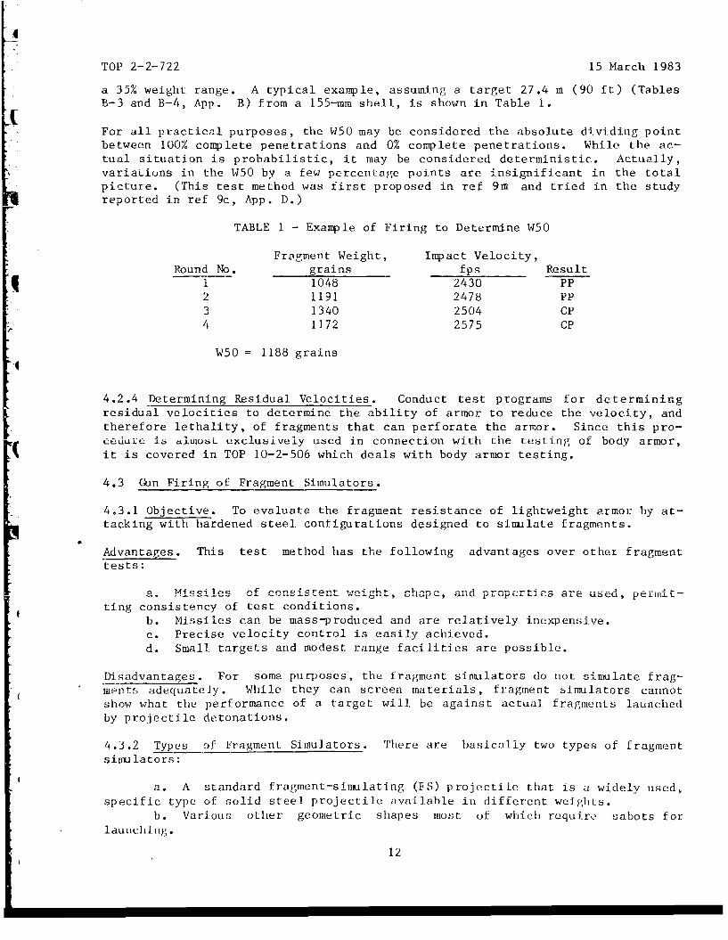
a 35% weight range. A typical example, assuming a target 27.4 m (90 ft) (Tables
B-3 and B-4, App. B) from a 155--mm shell, is shown in Table 1.
For all practical purposes, the W50 may be considered the absolute dividing pointbetween 100% complete penetrations and 0% complete penetrations. While the ac-tual situation is probabilistic, it may be considered deterministic. Actually,variaLiuns in the W50 by a few percentage points are insignificant in the totalpicture. (This test method was first proposed in ref 9m and tried in the studyreported in ref 9c, App. D.)
TABLE 1 - Example of Firing to Determine W50
Fragment Weight, Impact Velocity,Round No. grains fps Result
1 1048 2430 PP2 1191 2478 PP3 1340 2504 CP4 11.72 2575 CP
W50 = 1188 grains
4.2.4 Determining Residual Velocities. Conduct test programs for determiningresidual velocities to determine the ability of armor to reduce the velocity, andtherefore lethality, of fragments that can perforate the armor. Since this pro-cedure ib almuoL exclusively used in connection with the testing of body armor,it is covered in TOP 10-2-506 which deals with body armor testing.
4.3 Gun Firing of Fragment Simulators.
4.3.1 Objective. To evaluate the fragment resistance of lightweight armor by at-tacking with hardened steel configurations designed to simulate fragments.
Advantages. This test method has the following advantages over other fragmenttests:
a. Missiles .. f consi.stent weight, shap•e, a-nd propc"t•,es are used, p-rUit--ting consistency of test conditions.
b. Missiles can be mass-produced and are relatively inexpensive.c. Precise velocity control is easily achieved.d. Small targets and modest range facilities are possible.
Disadvantages. For some purposes, the fragment simulators do not simulate frag-mpnts adequately. While they can screen materials, fragment simulators cannotshow what the performance of a target will be against actual fragments launchedby projectile detonations.
4.3.2 Types of Fragment Simulators. There are basically two types of fragmentsimulators;
a. A standard fragment-simulating (FS) projectile that is a widely used,specific type of solid steel projectile available in different weights.
b. Various other geometric shapes most of which require sabots forlaunching.
12
TOP 2-2-722 15 March 1983
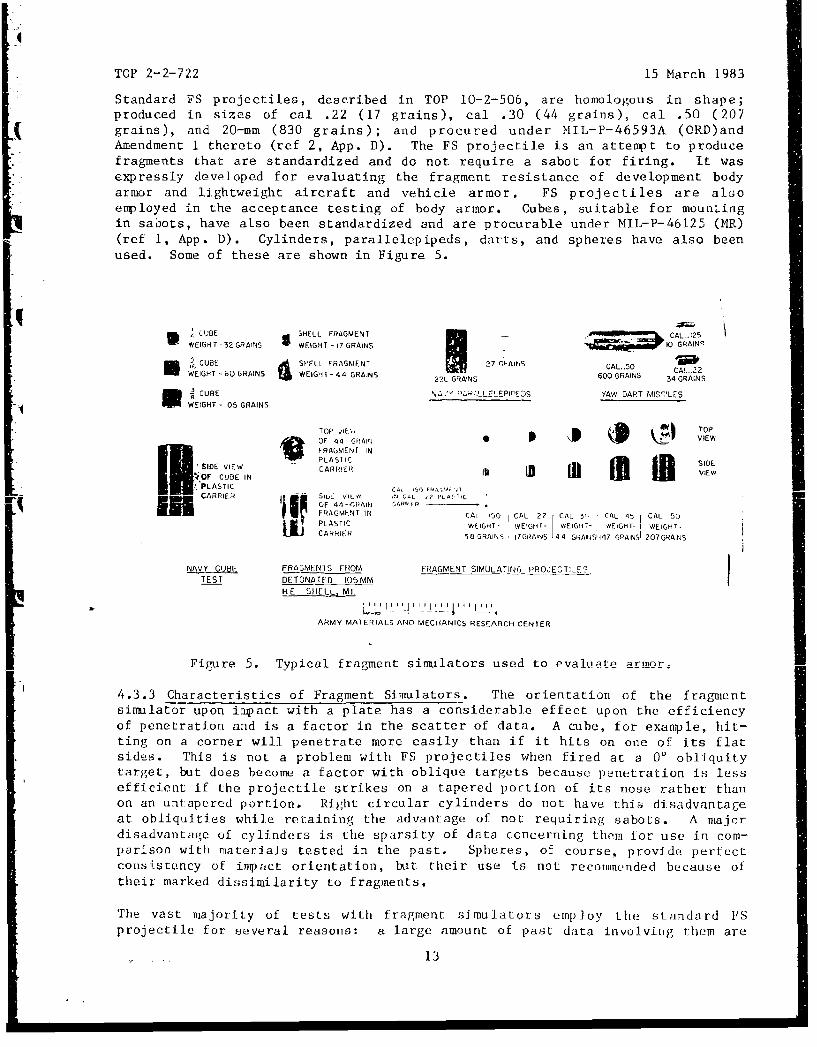
Standard FS projectiles, described in TOP 10-2-506, are homologous in shape;produced in sizes of cal .22 (17 grains), cal .30 (44 grains), cal .50 (207grains), and 20-mm (830 grains); and procured under MIL-P-46593A (ORD)andAmendment 1 thereto (ref 2, App. D). The FS projectile is an attempt to producefragments that are standardized and do not require a sabot for firing. It wasexpressly developed for evaluating the fragment resistance of development bodyarmor and lightweight aircraft and vehicle armor. FS projectiles are alsoemployed in the acceptance testing of body armor. Cubes, suitable for mountingin sabots, have also been standardized and are procurable under MIL-P-46125 (MR)(ref 1, App. D). Cylinders, parallelepipeds, darts, and spheres have also beenused. Some of these are shown in Figure 5.
CUBE SHELL FRAGMENT CAL.125
WEFGHT -32 GRAINS E -I17 GRAINS 10 GRAINq
CUBE SP-ELL FRAGMENT 27 T-AiS CAL40WEIGHT -60 GRAINS WEIGHT- 44 GRAINS 22L GRAINS 600 GRAINS 34 GRAINS
* •CUBE N .'P' P,'LLELEPICEDS YAW DART MIS,'LE5S"WEIGHT - 105 GRAINS
ilil• "•lili•FRAGMENT INm
PLAS IC S DESIDE VIE• CARRSI? Ii VIEW
'OF CUBE INPLASTIC CA, 51, 'RAV'; ITCARRIER S 16 V5 C-'L '? 'LACTIC
OF 44-AFlAIN C4Rýp-q FRAGMENT IN CAL "0 CAL 22 CAL 3r1. CAL -15 CAL 50iI PLASTIC WEIGHB - I WEIGHt- WEIGH.- ,EIGHT- WEIGHT-
58GRAINS IZIGRAINS 44 GFAIrNI517 GRAINS 207GRA.NS
NAVY C'JBL FRAGMENIS FROM FRAGMENT SIMULATING PROJECTIL-ESTEST DETONATED 105 MM
HE SHELL. MI.SIII j 2 II J I Il l f IF I II I
ARMY MATERIALS AND MECHANICS RESEARCH CENTER
Figure 5. Typical fragment simulators used to evalnafe armnor,
4.3.3 Characteristics of Fragment Simulators. The orientation of the fragmentsimulator upon impact with a plate has a considerable effect upon the efficiencyof penetration and is a factor in the scatter of data. A cube, for example, hit-ting on a corner will penetrate more easily than if it hits on one of its flatsides. This is not a problem with FS projectiles when fired at a 0' obliquitytarget, but does become a factor with oblique targets because penetration is lessefficient if the projectile strikes on a tapered portion of its nose rather thanon an untapered portion. Right circular cylinders do not have this disadvantageat obliquities while retaining the advantage of not requiring sabots. A majordisadvantage of cylinders is the sparsity of data concerning them for use in com-parison with materials tested in the past. Spheres, of course, provide perfectconsistency of impact orientation, but their use is not recommended because oftheir marked dissimilarity to fragments.
The vast majority of tests with fragment simulators employ the standard I'S
projectile for several reasons: a large amount of past data involving them are
13
TOP 2-2-722 15 March 1983
available; they are readily available in several weights, relatively inexpensiveto fire, and they reasonably simulate fragments. Thus, nearly all body armortesting (TOP 10-2-506) and much vehicle armor testing is performed with FSprojectiles.
* 4.3.4 Method.
4.3.4.1 Types of Tests. The type of test conducted depends on the resources(funds and target area) available and the objective of the test program.
a. The simplest test program involves obtaining a 6-round, V50 protec-tion ballistic limi.t, using the up-and-down firing technique (TOP 2-2-710).Pertinent velocities are limited to a spread of 46 m/sec. This type of ballistic
* limit is considered marginal since it is not accurate enough for most applica-tions. Acceptance testing of body armor (ref 3, App. D) upgrades this testmethod somewhat by requiring a 10-round, V50 ballistic limit with pertinentvelocities limited tc a velocity spread of 38 m/sec (125 ft/sec). If a ballisticlimit is not reached within a spread of 38 m/see, a 14-shot ballistic limit witha spread of 46 m/sec :is acceptable.
4 b. A second testing method that employs the Langlie firing technique* (TOP 2-2-710) which generally involves 12 to 16 firings, may produce a standard
deviation as well as a V50 ballistic limit, and is suitable for comparing typesof materials with regard to V50. This is the minimum test that should be usedfor comparing materials.
c. Occasionally, another method is employed when there is a need to ob-tain a very precise measurement of the ballistic limit and its standard devia-tion. In this case, the Probit method (see TOP 2-2-710) is preferred, with per-haps 50 to 200 fragment simulators fired, composed of groups of 8 or 15 fired ateach of 6 to 15 velocities that cover the range from V-O to V-100.
In firing, a gun-to-target distance of 4.9 m (16 ft) is considered standard forbody armor, with two lumiline screens spaced about I m (3 ft) apart for velocitymeasurements. (Special tests may have shorter distances as illustrated in TOP
S10-2-506.) For heavy materials requiring medium-sized guns, gun-to-target dis-tances to i2 m (40 ft) may be necessary. Witness material of 0.051-cm (0.020-in)aLUrrcLnium is placed behind the target to register complete and partial penetra-tions. When applicable, a yaw card is placed just in front of the target to in-dicate impact cr-ientations. If residual velocities are required, they are ob-taired as specified in TOP 10-2-506.
4.3.5 Data Required. Record all data pertinent to the armor material, includingtype, weight per square foot, and, when applicable, thickness, hardness, impacttoughness, yield strength, tensile strength, and chemical composition. Recordthe exact obliquity of the armor and the striking velocity of each partial andcomplete penetration. As required by the directive, residual velocity of thefragment after it passes through the armor, and velocity, size, and distributionof the fragments displaced from the target may be recorded as in paragraph 4.2.b.Describe impact orientations when pertinunt.
4.3.6 Analytical Plan. Use striking velocities and the corresponding penetra-tion results to estimate the mean and standard d,.viation parameters of a normaldistribution. It is assumed that the probabiliLy of penetration versus striking
14
TOP 2-2-722 15 March 1983
velocity is described by a cumulative normal distribution. If a zone of mixedresults does not occur, an estimate of standard deviation is not obtainable from
Vthe data. The zone of mixed results is the difference in striking velocity ofthe partial penetration with the highest velocity and the complete penntrationwith the lowest velocity. This difference must be positive to have a zone ofmixed results.
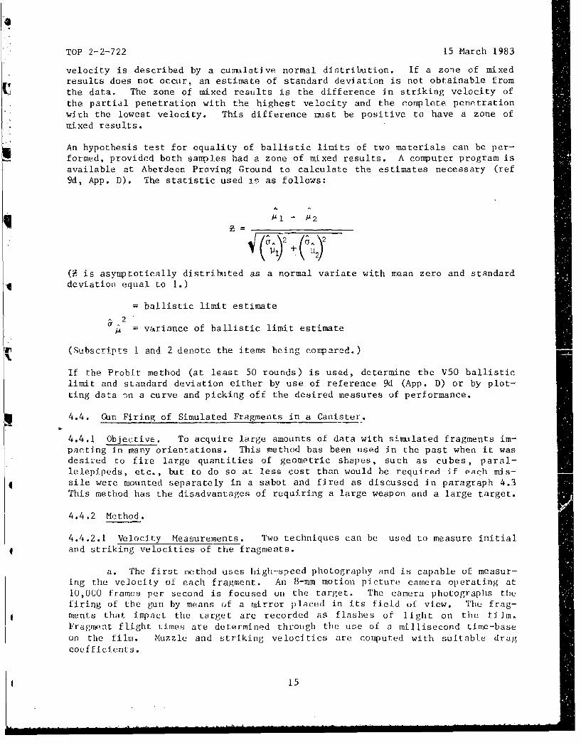
An hypothesis test for equality of ballistic limits of two materials can be per-formed, provided both samples had a zone of mixed results, A computer program isavailable at Aberdeen Proving Ground to calculate the estimates necessary (ref9d, App. D). The statistic used is as follows:
A
(F is asymptotically distributed as a normal variate with mean zero and standarddeviation equal to 1.)
- ballistic limit estimate
-2S= variance of ballistic limit estimate
(Subscrrpts I and 2 denote the items being compared.)
If the Probit method (at least 50 rounds) is used, determine the V50 ballisticlimit and standard deviation either by use of reference 9d (App. D) or by plot-ting data 7,n a curve and picking off the desired measures of performance.
4.4. Gin Firing of Simulated Fragments in a Canister.
4.4.1 Objective. To acquire large amounts of data with simulated fragments im-pacting in many orientations. This method has been used in the past when it wasdesired to fire large quantities of geometric shapes, such as cubes, paral-lelepipeds, etc., but to do so at less cost than would be required if esch mis-sile were mounted separately in a sabot and fired as discussed in paragraph 4.3This method has the disadvantages of requiring a large weapon and a large target.
4.4.2 Method.
4.4.2.1 Velocity Measurements. Two techniques can be used to measure initialand striking velocities of the fragments.
a. The first method uses high-speed photography and is capable of measur-ing the velocity of each fragment. An 8-mm motion picture camera operating at10,000 frames per second is focused on the target. The camera photographs thefiring of the gun by means of a mirror placed in its field of view. The frag-ments that impact the target are recorded as flashes of light on the film.Fragment flight times are determined through the use of a millisecond time-baseon the film. Muzzle and striking velocities are computed with suitable dragcoefficients.
15
TOP 2-2-722 15 March 1983
b. The second method measures the velocity of the fastest moving fragmentthat strikes each of two targets. Three printed silver circuit screens are used,one positioned on each target plate acting as the stop, and the third, or startscreen, located 6 m (20 ft) from the muzzle. The muzzle velocity and strikingvelocity are computed for the first fragment that arrives at each target.
4.4.2.2 Duplicating Specific Attack Conditions. The explanation behind this typeof testing is contained in paragraph 4.2.3. Using the canister approach, fireall fragments to strike at a given velocity at one time, at a velocity thatrepresents the actual velocity expected of fragments from a particular projec-tile. (Fragment velocities have some spread, but within acceptable limits.) Thetargets need not be only armor plates since vehicles are also appropriate targetsfor this type of firing.
4.4.2.3 Determination of V50 Levels. Fire canisters loaded with fragments of thedesired weight at the target plates at several velocities, and the percent ofpartial penetrations is obtained for each velocity by dividing the number of par-tials by the total number of hits. Vary propellant weights either up or down un--til a curve of velocity versus percent of partial penetrations is obtained.
4.4.3 Data Required. Record the following:
a. Number of fragments fired in each weight classb. Shape, weight, and hardness of the fragments in each weight categoryc. Striking velocity of the fragmentsd. Test plate material, alloy, thickness, mechanical properties, chemical
composition, and heat treatmente. Number of partial penetrations for each fragment weight class
4.4.4 Analytical Plan. If target materials are to be compared using the tech-nique of paragraph 4.4.2.2, use a statistical approach which tests the hypothesisthat each of the plates is equal when performance is judged on the basis of nun-ber of complete penetrations or compared to number of impacts. Unless otherwisespecified, a risk at both ends of 10% is assumed and the t-test used.
If a V50 ballistic limit is to be estimated (para 4.4.2.3), plot a curve of per-cenL complete penetrations (ordinate) versus striking velocity (abscissa) andpick the V50 point off the curve. If several thicknesses of the same materialhave been tested, also plot ballistic limit versus areal density.
If a vehicle is being fired upon, record the impact location and the damagecaused by each impacting fragment, and evaluate the implications of this damage.
4.5. Static Detonation of HE Projectiles Against Armored Vehicles.
4.5.1 Objective. To evaluate the effectiveness of a vehicle including its coof,hatch covers, doors, front, rear and side armor, etc., in protecting againstblast and shell fragments. This basic objective may or may not be related toproviding data to validate or improve a mathematical model concerned with protec-tion afforded by vehicles in realistic battlefield scenarios.
4.5.2 Standards. Protection requirements in ROC's/DP's are now being stated interms of a specified probability of no perforations from a specified projectilebursttng at random locations around a formation of specific vehicles in a
16
TOP 2-2-722 15 March 1983
realistic tactical battlefield scenario. For example, the requirement mightstate that when forty 105-mm projectiles are detonated in the air above aformation of eight XYZ vehicles, the probability of a complete perforation shouldnot exceed 0.3 per round. Two computerized mathematical models have beendeveloped for determining the perforation probability from given input condi-tions. Reference 12 (App. D) describes one model developed by Littleton Researchand Engineering Corp. for TACOM and includes an explanation for determining thesingle-shot perforation probability. AMSAA has developed a different model.Periodic validation of the mathematical models requires the detonation of shellat specified locations from a test vehicle.
4.5.3 Method. The test procedures generally follow those perforimd on a testreported in reference 9h (App. D). The number of shell and location of burstpoints depends upon the computer program that is chosen and the resources avail-able. The test plan prepared by AMSAA or Littleton will specify the number ofshells to be detonated, their height and location above the ground or above thevehicle, and the shell orientations. Constraints will be imposed upon the numberof firings by funding and time available. To reduce costs, it is advisable touse more than one target vehicle or to supplement target vehicle(s) with armorplate of the same type, thickness, and obliquity as that of the vehicle. Painttargets with grid lines to help identify locations of perforations. Positionshells, one at a time, at a specific location and orientation, and electricallydetonated. Paint vehicles with grid lines to help identify locations offragments.
4.5.4 Data Required. For each detonation, record the following information:
a. Projectile type, location, and orientation with respect to each targetb. Location of each target vehicle; type, thickness, obliquity, and area of
pertinent armor areasc. Location and orientation of target plates, if used; also thickness,
area, and types of target platesd. Locations, number, and definition of significant impacts (para 4.1.4)e. Locations, number, and definition of perforations (para 4.1.4)f. Damage to components of vehicles, e.g., periscopesg. Blast effects
4.5.5 Analytical Plan. lf repeated shots under identical conditions are fired,
develop data as described in paragraph 4.1.4. If the detonation occurs at a mul-
titude of locations in accordance with a test plan to validate a mathematicalmcdel, the results are tabulated and forwarded to the appropriate agency (AMSAAor TACOM) for analysis. The results can be used to improve curves such as thoseof Figure 4. The roof armor often is the only area of concern because projec-tiles detonating overhead will usually strike side and end armor at highobliquities, and the armor is usually fairly thick to protect against small armsprojectiles.
17
4
TOP 2-2-722 15 March 1983
SRecommended changes of this publication should be forwardedlto Commander, US Army Test and Evaluation Command, ATTN:IDRSTE-AD-M, Aberdeen Proving Ground, Md. 21005. Technicallinformation may be obtained from the preparing activity:Commander, US Army Aberdeen Proving Ground, ATTN: STEAP-MT-M, Aberdeen Proving Ground, Md 21005. Additional copiesare available from the Defense Technical Information CenterCameron Station, Alexandria, Va. 22314. This document isiidentified by the accession number (AD No.), printed on thefirst page.
ki
18
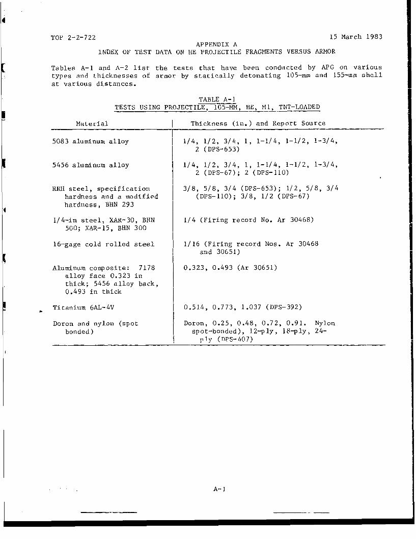
TOP 2-2-722 15 March 1983APPENDIX A
INDEX OF TEST DATA ON HE PROJECTILE FRAGMENTS VERSUS ARMOR
Tables A-1 and A-2 list the tests that have been conducted by APG on varioustypes and thicknesses of armor by statically detonating 105-mm and 155-mm shellat various distances.
TABLE A-1TESTS USING PROJECTILE, 105-MM, HE, MI, TNT-LOADED
Material Thickness (in.) and Report Source
5083 aluminutu alloy 1/4, 1/2, 3/4, 1, 1-1/4, 1-1/2, 1-3/4,2 (DPS-653)
5456 aluminum alloy 1/4, 1/2, 3/4, 1, 1-1/4, 1-1/2, 1-3/4,2 (DPS-67); 2 (DPS-110)
RRH steel, specification 3/8, 5/8, 3/4 (DPS-653); 1/2, 5/8, 3/4hardness and a modified (DPS-110); 3/8, 1/2 (DPS-67)hardness, BHN 293
1/4-in steel, XAR-30, BHN 1/4 (Firing record No. Ar 30468)500; XAR-15, BHN 300
16-gage cold rolled steel 1/16 (Firing record Nos. Ar 30468and 30651)
Aluminum composite: 7178 0.323, 0.493 (Ar 30651)alloy face 0.323 inthick; 5456 alloy back,0.493 in thick
Titanium 6AL-4V 0.514, 0.773, 1.037 (DPS-392)
Doron and nylon (spot Doron, 0.25, 0.48, 0.72, 0.91. Nylonbonded) spot-bonded), 12-ply, 18-ply, 24-
niy (DP$- 407)
A-i
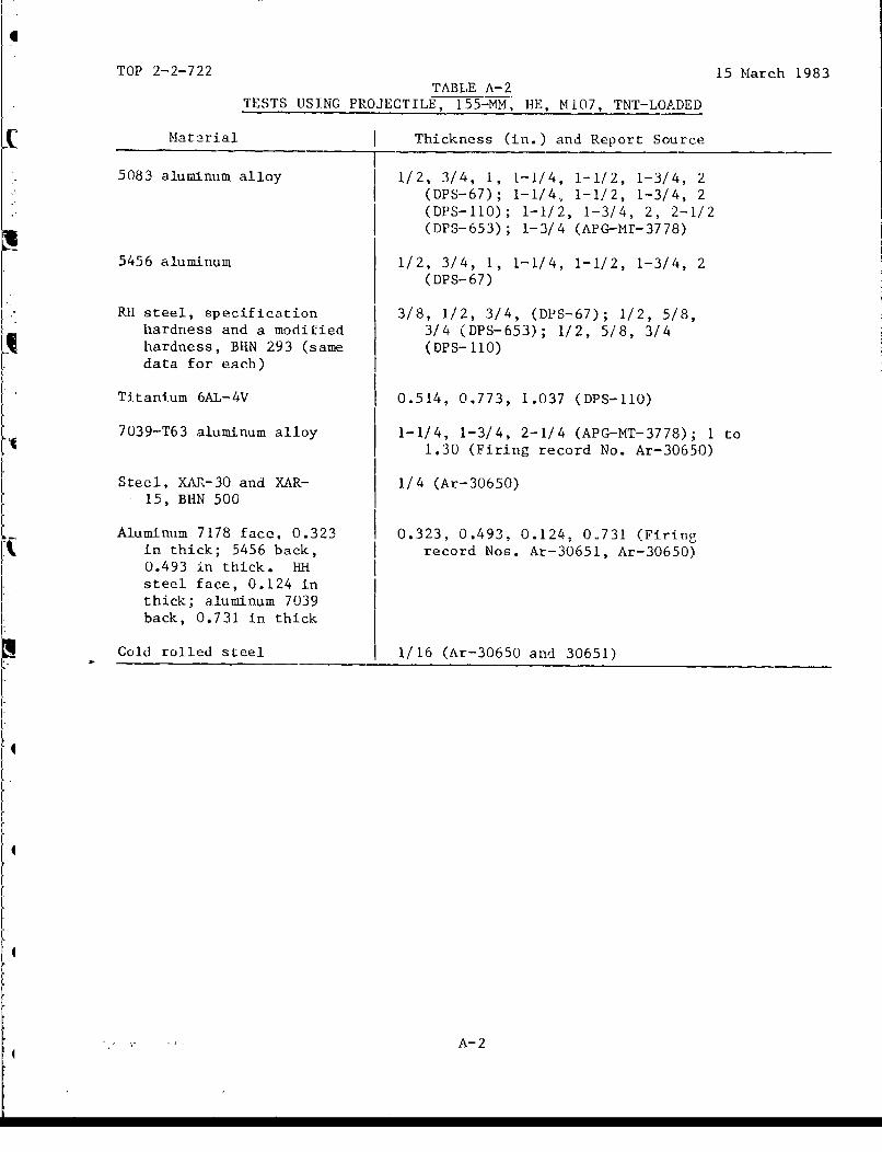
TOP 2-2-722 15 March 1983TABLE A-2
TESTS USING PROJECTILE, 155-MM, HE, MI07, TNT-LOADED
Material Thickness (in.) and Report Source
5083 aluminum alloy 1/2, 3/4, 1, t-1/4, 1-1/2, 1-3/4, 2
(DPS-67); 1-1/4, 1-1/2, 1-3/4, 2(DPS-110); 1-1/2, 1-3/4, 2, 2-1/2(DPS-653); 1-3/4 (APG-Mr-3778)
5456 aluminum 1/2, 3/4, 1, 1-1/4, 1-1/2, 1-3/4, 2(DPS-67)
RH steel, specification 3/8, 1/2, 3/4, (DPS-67); 1/2, 5/8,hardness and a modified 3/4 (DPS-653); 1/2, 5/8, 3/4hardness, BHN 293 (same (DPS-110)data for each)
Titanium 6AL-4V 0.514, 0.773, 1.037 (DPS-110)
7039-T63 aluminum alloy 1-1/4, 1-3/4, 2-1/4 (APG-MT-3778); 1 to
1.30 (Firing record No. Ar-30650)
Steel, XAR-30 and XAR- 1/4 (Ar-30650)15, BHN 500
Aluminum 7178 face, 0.323 0.323, 0.493, 0.124t 0.731 (Firingin thick; 5456 back, record Nos. Ar-30651, Ar-30650)0.493 in thick. HHsteel face, 0.124 inthick; aluminum 7039back, 0.731 in thick
Cold rolled steel 1/16 (Ar-30650 and 30651)
A-2
TOP 2-2-722 15 March 1983APPENDIX B
FRAGMENT CHARACTERISICS OF 105-MM AND 155-M SHELLa
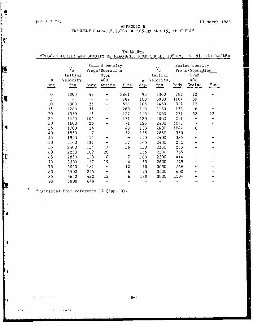
TABLE B-1INITIAL VELOCITY AND DENSITY OF FRAGMENTS FROM SHELL, 105-MM, HE, 141, TNT-LOADED
Scaled Density. Scaled Density
V0 Frags/Steradian 0o Frags/Steradian
Initial Over Initial Over0 Velocity, 400 0 Velocity, 400
deg fps Body Grains Fuze deg. fps Body Grains Rize
0 1000 67 - 3841 95 3300 785 12 -
5 - - - 787 100 3000 1104 89 -
10 1300 25 - 526 105 2450 314 12 -
15 1200 31 - 265 110 2150 174 6 -
20 1350 11 - 127 115 2050 271 32 1225 1650 104 - 171 120 2000 241 - -
30 1600 26 - 71 125 2400 1071 --
I 35 1700 14 - 48 130 2600 104/ 8 -
40 1850 7 - 52 135 2850 560 - -
45 1950 54 - - 140 2400 385 - -
50 2100 121 - 37 145 2400 262 - -
55 2400 134 7 36 150 2350 253 - -
60 2250 107 20 - 155 2300 355 - -
C 65 2850 129 6 7 160 2200 414 - -
70 3300 117 19 6 165 2600 749 - -75 3050 181 - 12 170 3050 769 - -
80 3500 225 - 6 175 3400 600 - -
85 3650 422 12 6 180 3800 1304 - -
90 3900 649 ...- - - - -
aExtracted from reference 14 (App. D).
B-
4
B-
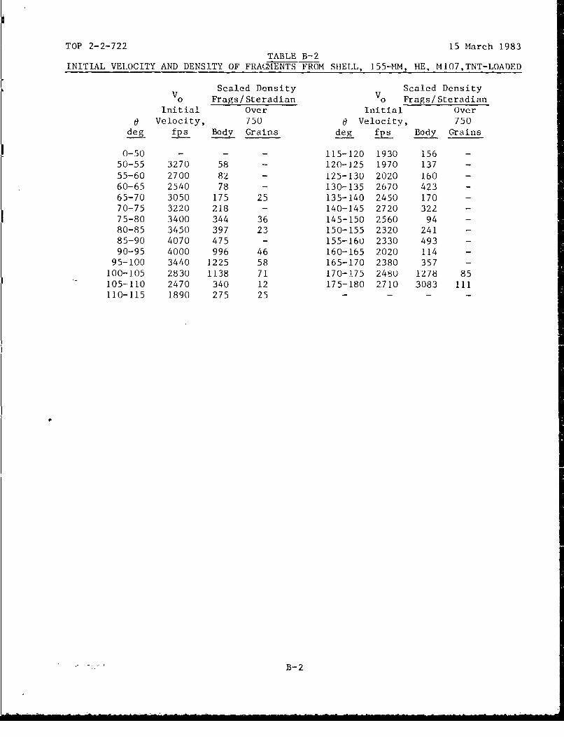
TOP 2-2-722 15 March 1983TABLE B-2
INITIAL VELOCITY AND DENSITY OF FRAcIENTS FROM SHELL, 155-Mm, HE, M107,TNT-LOADED
Scaled Density Scaled Density
V0 Frags/Steradian V0 Frags/Steradian
Initial Over Initial Overa Velocity, 750 0 Velocity, 750
deg fps Body Grains deg fps Body Grains
0-50 - - - 115-120 1930 156 -
50-55 3270 58 - 120-125 1970 137 -
55-60 2700 82 - 125-130 2020 Ib0 -
60-65 2540 78 - 130-135 2670 423 -
65-70 3050 175 25 135-140 2450 170 -70-75 3220 218 - 140-145 2720 322 -
75-80 3400 344 36 145-150 2560 94 -80-85 3450 397 23 150-155 2320 241 -
85-90 4070 475 - 155-160 2330 493 -
90-95 4000 996 46 160-165 2020 114 -
95-100 3440 1225 58 165-170 2380 357 -100-105 2830 1138 71 170-175 2480 1278 85105-110 2470 340 12 175-180 2710 3083 111110-115 1890 275 25 - - -
* " -: -
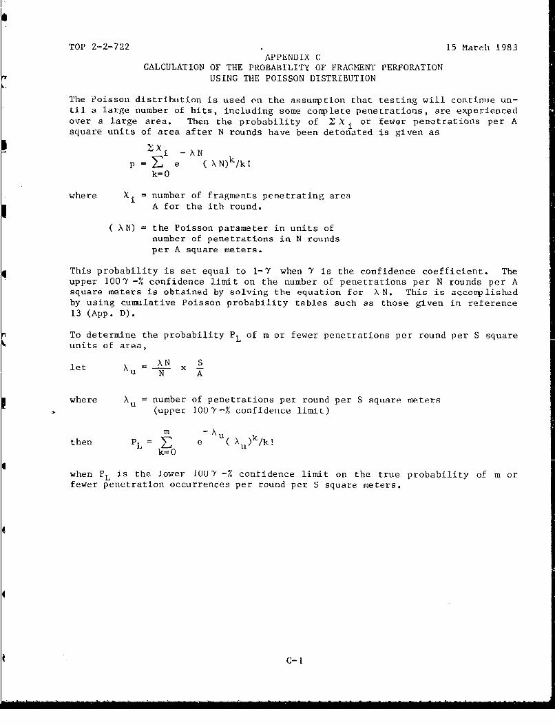
TOP 2-2-722 15 March 1983APPENDIX C
CALCULATION OF THE PROBABILITY OF FRAGMENT PERFORATIONUSING THE POISSON DISTRIBUTION
The Poisson distribution is used on the assumption that testing will continue un-til a large number of hits, including some complete penetrations, are experiencedover a large area. Then the probability of Ž2 Xi or fewer penetrations per Asquare units of area after N rounds have been detonated is given as
i -AN
p = E e ( N)k/k!k=0
where Xi = number of fragments penetrating areaA for the ith round.
(AN) = the Poisson parameter in units ofnumber of penetrations in N roundsper A square meters.
This probability is set equal to 1-7 when Y is the confidence coefficient. Theupper 1007 -% confidence limit on the number of penetrations per N rounds per Asquare meters is obtained by solving the equation for XN. This is acconplishedby using cumulative Poisson probability tables such as those given in reference13 (App. D).
To determine the probability PL of m or fewer penetrations per round per S squareunits of area,let X AN x S
N A
where Xu number of penetrations per round per S square meters(upper 100Y-% confidence limit)
m -uthen PL = E e ,u )k/k!
k= 0
when PL is the lower 1007 -% confidence limit on the true probability of m orfewer penetration occurrences per round per S square meters.
C-I
TOP 2-2-722 15 March 1983EXAMPLE
No. ofPenetrations
Round No. (Xi)1 2 N 82 1
N= 3 5 i--
Fired on area of 8.9 square meters = A
Probability (8 or few penetrations per 3 rounds on area A):
q 8=8 e-(XN) ( XN)k/k!
k= 0
= i-Y= 0.05 (confidence coefficient .95)
8
Therefore, the problem is to solve Y e- XN ( XN)k/k!= .05 for X N.k=O
This is done by entering Poisson tables with probability = .05 and C-1 - 8 andinterpolating to obtain the value of the Poisson parameter. These tables giveXN = 14.43 penetrations/3 rounds/8.9 square meters.
Suppose we wanted to find the probability of no penetrations per round per 9.3square meters; i.e.,
PL e0 Au ( X ) k/k!k= 0
x (i /s f'\ 9.3)Now N XN Li 14.43 I5.010N (A) \3 ''.9
PI e-5 .0 1 0 (5.010)0/0! = .0067
Xu is an upper 95% confidence limit on the true Poisson parameter X PL isthe lower 95% confidence limit on the true p = probability of no penetrationsper round per 9.3 square meters.
C-2
TOP 2-2-722 15 March 1983APPENDIX DREFERENCES
1. TOP 10-2-506, Ballistic Testing of Personnel Armor Materials, 6 Jan 75.
2. TOP 2--2-710, Ballistic Tests of Armor Materials, 6 Apr 77.
3. TOP 4-2-813, Static Fragmentation Tests of IHigh Explosive Munitions, 31 Jan80.
4. TOP 4-2-825, Flash Radiography in Ballistic Testing, 8 Jun 78.
5. TOP 4-2-805, Projectile Velocity Measurements, 21 September 1982.
6. MIL-F-46125 (MR), "Projectile Cubes, Fragment-Simulating," 21 September 1967.
7. MIL-P-46593A (ORD), "Projectile, Calibers .22, .30, .50 and 20-mmFragment-Simulating," and Amendment 1, 12 October 1964.
8. MIL-STD-662B, "Ballistic Acceptance Test Method for Personnel ArmorMaterial," 23 July 1971.
9. Aberdeen Proving Ground Reports:
a. Demaree, C. L., "A Study of Lethal Characteristics of Fr*igments Resultingfrom Impacts on Armor (Phase 1)," DPS-622 (Confidential), September 1962.
Sb. Demaree, C. L., "Research Test of Steel Armor Attacked byFragment-Simulating Cubes to Provide Data for Lethality Studies (U),"DPS-1098 (Confidential), October 1963.
c. Feroli, John A. and Van Caneghem, R. J., "Final Report on Special Studyof Methodology for Determining Protection Against Shell Fragments,"APG-MT--4363, 1974. (TECOM Project 9-CO-011-000-051.)
d. Visnaw, V., "Computer Program for Analysis of Sensitivity Data Followinga Normal Distribution," Analytical Section Report 70-AS-113, 16 October''IU.
e. Keithley, S. M., "Protection Provided by Titanium Armor AgainstHigh-Explosive Ammunition at a Bursting Distance of 50 Feet (U)," DPS-392(Confidential), December 1961.
f. Keithley, S. M., "Protection Provided by Nylon and Doron Armor Against LIEShell Fragments (90-Foot Yankee Stadium) (U)," DPS-407 (Confidential),December 1961.
g. Keithley, S. M., "Protection Provided by Aluminum and Steel Armor AgainstFragments Produced by High-Explosive Ammunition Bursting at VariousDistances (U)," DPS-653 (Confidential), September 1962.
h. Martin, C. E., Jr., "First Partial Report on Engineer Design Test ofArmor, Vehicle Design Procedure for Shell Fragment Protection (U),"
APG-MT-3309 (Confidential), October 1969.
D-1
TOP 2-2-722 15 March 1983i. Martin, C. E., Jr., "Engineer Design Test of Armor, Aluminum, Simulated
Roof Structures vs 155-mm, HE Fragments (U)," APG-MT-3778 (Confidential),February 1971. (Distribution controlled by US Army Tank-AutomotiveCommand, ATTN: AMCPM-MICV. AD 513 984L.)
j. Resnick, W. V., "Protection Provided by Steel and Aluminum Armor AgainstFragments from High Explosive Ammunition (U)," DPS-67 (Confidential), 22November 1960. (AD 1293)
k. Resnick, W. V., "Protection Provided by Steel and Aluminum Armor AgainstFragments from High Explosive Ammunition (U)," DPS-110 (Confidential),January 1961.
1. "X-Ray Multiflash System for Measurement of Projectile Performance at theTarget," BRL Technical Note 1634.
M. Feroli, John A., "Special Study of Procedures for Evaluating Protectionof Vehicles Against Projectiles and Fragments, Report APG-MT-4362,October 1973. (TECOM Project 9-CO-001-000-054.)
10. Aberdeen Proving Ground Firing Records:
a. Martin, C. E., Jr., "Engineer Design Test of Armor, High Hardness, RolledSteel for XM706 Series Armored Cars (HE Projectile Phase) (U)," Ar-30468(Confidential), 10 September 1971.
bý Martin, C. E., Jr., "Engineer Design TejL of Armor, Aluminum Alloy 7039Versus 155-mm HE Shell for ARSV (TACOM RKMA-19) (U)," Ar-30650(Confidential), 22 December 1971.
c. Martin, C. E., Jr., "Engineer Design Test of Armor, High Hardness, RolledSteel for XM706 Series Armored Cars (HE Versus Aluminum Armor Phase)(U),' Ar-30651 (Confidential), 27 January 1972.
11. Acceptance Test Procedure AAA-PFE-1, "Aluminum Alloy Armor - Plate, Forged,Extruded," Aberdeen Proving Ground, Md., 13 September 1971.
12. Reed, F. E. and Orner, R. G . "S ist Tesv Proc.dur. for Evalat-ingPenetration by Shell Fragments," Littleton Research and EngineeringCorporation Report, June 1969.
13. "Biometrika Tables for Statisticians," vol I, edited by E. S. Pearson andH. 0. Hartley, University Press, Cambridge, Mass., 1966.
14. M4101-62-3 Joint Munition Effectiveness Manuals/Surface-to-Surface (JMEM/SS)Fragmentation Characteristics and Terminal Effects Data for Surface-to-SurfaceWeapons, Revision 1, 1 July 1982.
D-2