Embed Size (px)
Citation preview
INCH-POUNDMIL-PRF-62420A(AT)23 January 1997SUPERSEDINGMIL-P-62420(AT)8 June 1990
PERFORMANCE SPECIFICATION
PERISCOPE, TANK
This specification is approved for use by the U.S. Army Tank-automotiveand Armaments Command, Department of the Army, and is available foruse by all Departments and Agencies of the Department of Defense.
1. SCOPE
1.1 Scope. This specification covers the laser protected tank periscope assemblies. Unless otherwise specified herein, these items will be referred to as “periscopes”. Theseperiscopes are used as unity vision devices in combat type vehicles.
1.2 Classification. Periscopes will be identified as follows (see 6.2):
Army Drawing ItemPIN dash number
(see 6.3)
12357792 - Periscope, Tank: M27E4 -112357794 - Periscope, Tank: M37E1 -212357840 - Periscope, Tank: Laser Protective -
M1 Commander Short-3
Beneficial comments (recommendations, additions, deletions) and any pertinent data whichmay be of use in improving this document should be addressed to: U.S. Army Tank-automotiveand Armaments Command, ATTN: AMSTA-TR-E/BLUE, Warren, MI 48397-5000, by usingthe Standardization Document Improvement Proposal (DD Form 1426) appearing at the end ofthis document, or by letter. AMSC N/A FSC 1240DISTRIBUTION STATEMENT A. Approved for public release; distribution is unlimited.
Downloaded from http://www.everyspec.com
MIL-PRF-62420A(AT)
2
Army Drawing ItemPIN dash number
(see 6.3)
12357841 - Periscope, Tank: Laser Protective - M1 Commander Tall
-4
12357846 - Periscope, Tank: Laser Protection - M1 Driver Short
-5
12357848 - Periscope, Tank: Laser Protective - M1 Driver Wide
-6
12357850 - Periscope, Tank: M26E1 -712357908 - Periscope, Tank: Laser Protective -
15° Uplook-8
12357909 - Periscope, Tank: Laser Protective - 20° Uplook
-9
12357918 - Periscope, Tank: M17E4 -1012370033 - Periscope, Tank: Driver’s M45E4 -1112370322 - Periscope, Tank: M47E1 -1212370393 - Periscope, Tank: M17CE1 -13
2. APPLICABLE DOCUMENTS
2.1 General. The documents listed in this section are specified in sections 3 and 4 of thisspecification. This section does not include documents cited in other sections of this specificationor recommended for additional information or as examples. While every effort has been made toensure the completeness of this list, document users are cautioned that they must meet allspecified requirement documents cited in sections 3 and 4 of this specification, whether or notthey are listed.
2.2 Government documents.
2.2.1 Specifications, standards, and handbooks. The following specifications, standards,and handbooks form a part of this document to the extent specified herein. Unless otherwisespecified, the issues of these documents are those listed in the issue of the Department of DefenseIndex of Specifications and Standards (DoDISS) and supplement thereto, cited in the solicitation(see 6.2).
Downloaded from http://www.everyspec.com
MIL-PRF-62420A(AT)
3
SPECIFICATIONS
DEPARTMENT OF DEFENSE
MIL-H-6083 - Hydraulic Fluid, Petroleum Base for Preservation andOperation.
MIL-H-46170 - Hydraulic Fluid, Rust Inhibited, Fire Resistant SyntheticHydrocarbon Base.
MIL-F-62422 - Filter, Laser Hazard Protection.
STANDARDS
DEPARTMENT OF DEFENSE
MIL-STD-810 - Environmental Test Methods and EngineeringGuidelines.
(Unless otherwise indicated, copies of the above specifications, standards, and handbooksare available from the Standardization Document Order Desk, 700 Robbins Avenue, Building 4D,Philadelphia, PA 19111-5094.)
2.2.2 Other Government documents, drawings, and publications. The following otherGovernment documents, drawings, and publications form a part of this document to the extentspecified herein. Unless otherwise specified, the issues are those cited in the solicitation.
NUCLEAR REGULATORY COMMISSION (NRC)
Code of Federal Regulations (CFR) - Title 10, Parts 30 and 40.
(Copies of the Code of Federal Regulations (CFR) are available from the Superintendentof Documents, U.S. Government Printing Office, Washington, DC 20402.)
DRAWINGS
12357792 - Periscope, Tank: M27E4. 12357794 - Periscope, Tank: M37E1.
12357840 - Periscope, Tank: Laser Protective - M1 Commander Short.12357841 - Periscope, Tank: Laser Protective - M1 Commander Tall.12357846 - Periscope, Tank: Laser Protective - M1 Driver Short.12357848 - Periscope, Tank: Laser Protective - M1 Driver Wide.12357850 - Periscope, Tank: M26E1.12357908 - Periscope, Tank: Laser Protective - 15° Uplook.
Downloaded from http://www.everyspec.com
MIL-PRF-62420A(AT)
4
12357909 - Periscope, Tank: Laser Protective - 20° Uplook.12357918 - Periscope, Tank: M17E4.12370033 - Periscope, Tank: Driver’s M45E4.12370322 - Periscope, Tank: M47E1.12370393 - Periscope, Tank: M17CE1.
(Copies of these drawings are available from the U.S. Army Tank-automotive andArmaments Command, ATTN: AMSTA-TR-E/BLUE, Warren, MI 48397-5000.)
2.3 Non-Government publications. The following documents form a part of thisdocument to the extent specified herein. Unless otherwise specified, the issues of the documentswhich are DoD adopted are those listed in the issue of the DoDISS cited in the solicitation. Unless otherwise specified, the issues of documents not listed in the DoDISS are the issues of thedocuments cited in the solicitation (see 6.2).
AMERICAN SOCIETY FOR TESTING AND MATERIALS (ASTM)
ASTM E308 - Standard Practice for Computing the Colors of Objects byUsing the CIE System (DoD Adopted).
(Copies of ASTM publications may be obtained from the American Society forTesting and Materials, 100 Barr Harbor Drive, West Conshohocken, PA 19428-2959.)
NATIONAL INSTITUTE OF STANDARDS AND TECHNOLOGIES (NIST)
NIST, Neutral Density Filters Pamphlet.
(Copies of NIST publications may be obtained from the National Institute of Standardsand Technology, Standards and Codes Info; Room A163 Bldg 411, Gaithersburg, MD 20899.)
2.4 Order of precedence. In the event of a conflict between the text of this documentand the references cited herein, the text of this document takes precedence. Nothing in thisdocument, however, supersedes applicable laws and regulations unless a specific exemption hasbeen obtained.
3. REQUIREMENTS
3.1 First article. When specified (see 6.2), a sample shall be subjected to first articleinspection in accordance with 4.3.
3.2 Materials. Materials shall be as specified herein, in applicable standards andspecifications and on applicable drawings (see 4.5.1).
Downloaded from http://www.everyspec.com
MIL-PRF-62420A(AT)
5
3.2.1 Recycled, recovered, or environmentally preferable materials. Recycled,recovered, or environmentally preferable materials should be used to the maximum extent possibleprovided that the material meets or exceeds the operational and maintenance requirements, andpromotes economically advantageous life cycle costs.
3.2.2 Hazardous materials. Asbestos, Cadmium, and radioactive material will not beused in this item. Radioactive material is defined by CFR, Title 10, Parts 30 and 40, and otherradioactive material in which the radioactivity is greater than 0.002 microcuries per gram or0.01 microcuries total activity for the item.
3.2.3 Dissimilar metals. Contact between dissimilar metals which encourages galvanicaction shall be avoided.
3.3 Design and construction. The laser protected tank periscopes shall be manufacturedin accordance with the applicable drawing to the periscope specified (see 6.2) and all drawingspertaining thereto from the following (see 4.5.1):
12357792 1235785012357794 1235790812357840 1235790912357841 1235791812357846 1237003312357848 12370322
12370393
3.4 Performance.
3.4.1 Optical characteristics.
3.4.1.1 Resolution. The periscope shall permit resolution of a test pattern subtendingone (1) minute of arc within the resolving area as specified in the applicable drawing listed in 3.3(see 4.5.6.1).
3.4.1.2 Spherical power. Spherical power shall be within the range of minus (-) 0.50 toplus (+) 0.25 diopter (see 4.5.6.2).
3.4.1.3 Astigmatism. Astigmatism shall not exceed 0.25 diopter (see 4.5.6.3).
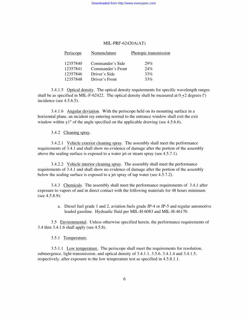
3.4.1.4 Photopic transmission. The photopic transmission of laser protected periscopes,excluding M1 periscopes, shall be equal to or greater than 36 percent (%). The photopictransmission of M1 periscopes shall be equal to or greater than the value specified below. Thephotopic transmission shall be measured at 0 +2 degrees incidence (see 4.5.6.4):
Downloaded from http://www.everyspec.com
MIL-PRF-62420A(AT)
6
Periscope Nomenclature Photopic transmission
12357840 Commander’s Side 29%12357841 Commander’s Front 24%12357846 Driver’s Side 33%12357848 Driver’s Front 33%
3.4.1.5 Optical density. The optical density requirements for specific wavelength rangesshall be as specified in MIL-F-62422. The optical density shall be measured at 0 +2 degrees (°)incidence (see 4.5.6.5).
3.4.1.6 Angular deviation. With the periscope held on its mounting surface in ahorizontal plane, an incident ray entering normal to the entrance window shall exit the exitwindow within +1° of the angle specified on the applicable drawing (see 4.5.6.6).
3.4.2 Cleaning spray.
3.4.2.1 Vehicle exterior cleaning spray. The assembly shall meet the performancerequirements of 3.4.1 and shall show no evidence of damage after the portion of the assemblyabove the sealing surface is exposed to a water jet or steam spray (see 4.5.7.1).
3.4.2.2 Vehicle interior cleaning spray. The assembly shall meet the performancerequirements of 3.4.1 and shall show no evidence of damage after the portion of the assemblybelow the sealing surface is exposed to a jet spray of tap water (see 4.5.7.2).
3.4.3 Chemicals. The assembly shall meet the performance requirements of 3.4.1 afterexposure to vapors of and in direct contact with the following materials for 48 hours minimum(see 4.5.8.9):
a. Diesel fuel grade 1 and 2, aviation fuels grade JP-4 or JP-5 and regular automotiveleaded gasoline. Hydraulic fluid per MIL-H-6083 and MIL-H-46170.
3.5 Environmental. Unless otherwise specified herein, the performance requirements of3.4 thru 3.4.1.6 shall apply (see 4.5.8).
3.5.1 Temperature.
3.5.1.1 Low temperature. The periscope shall meet the requirements for resolution,submergence, light transmission, and optical density of 3.4.1.1, 3.5.6, 3.4.1.4 and 3.4.1.5,respectively, after exposure to the low temperature test as specified in 4.5.8.1.1.
Downloaded from http://www.everyspec.com
MIL-PRF-62420A(AT)
7
3.5.1.2 High temperature. The periscope shall meet the requirements for 3.4.1.1resolution, 3.4.14 photopic transmission, 3.4.1.5 optical density, and 3.5.6 after exposure to hightemperature test as specified in 4.5.8.1.2.
3.5.1.3 Mirror and window lamination. The unit shall show no evidence of bond failure(see 4.5.8.1.3).
3.5.2 Humidity. The periscope shall meet the requirements for 3.4.1.1 resolution, 3.4.14photopic transmission, 3.4.1.5 optical density, and 3.5.6 after exposure to the humidity test asspecified in 4.5.8.2.
3.5.3 Salt fog. The periscope shall meet the requirements for 3.4.1.1 resolution, 3.4.14photopic transmission, 3.4.1.5 optical density, and 3.5.6 after exposure to the salt fog test asspecified in 4.5.8.3.
3.5.4 Vibration. The periscope shall meet the requirements for 3.4.1.1 resolution,3.4.1.4 photopic transmission, 3.4.1.5 optical density and 3.5.6 submergence, after exposure tothe vibration test (see 4.5.8.4).
3.5.5 Shock.
3.5.5.1 Basic shock. The periscope shall meet the requirements for 3.4.1.1 resolution,3.4.1.4 photopic transmission, 3.4.1.5 optical density and 3.5.6 submergence, after exposure tothe basic shock test as specified in 4.5.8.5.1.
3.5.5.2 Gun fire shock. The periscope shall meet the requirements for 3.4.1.1 resolution,3.4.1.4 photopic transmission, 3.4.1.5 optical density and 3.5.6 submergence, after exposure tothe gun firing shock test as specified in 4.5.8.5.2.
3.5.6 Submergence. No water leakage shall occur through the equipment seal andassembly as the equipment is retained on its mounting surface during test per 4.5.8.6.
3.5.7 Fungus. The assembly shall not support fungal growth when exposed toinoculation by spraying external surfaces with spore suspension (see 4.5.8.7).
3.5.8 Weathering. After meeting the performance and environmental requirements, theperiscope shall be capable of meeting the requirements of 3.5.1.3 mirror and window laminations,3.4.1.5 optical density, 3.5.8.1 resolution (modified), 3.5.8.2 spherical power (modified), and3.5.8.3 astigmatism (modified), and shall be otherwise functional and undamaged subsequent toexposure as specified in 4.5.8.8.
Downloaded from http://www.everyspec.com
MIL-PRF-62420A(AT)
8
3.5.8.1 Resolution (modified). Following weathering exposure of 4.5.8.8, the periscopeshall meet the requirement of 3.4.1.1, except that resolution shall be within 75 seconds of arc.
3.5.8.2 Spherical power (modified). Following weathering exposure of 4.5.8.8, theperiscope shall meet the requirements of 3.4.1.2, except that spherical power shall be within therange of -0.60 to +0.30 diopter.
3.5.8.3 Astigmatism and light transmission (modified). Following the weatheringexposure of 4.5.8.8, the periscope shall meet the requirements of 3.4.1.3 and 3.4.1.4, except thatastigmatism and light transmission shall not be degraded in excess of 20% of the value recordedprior to weathering tests.
3.6 Identification and marking. All items shall be individually identified and marked inaccordance with applicable drawings (see 4.5.2).
3.7 Workmanship. Workmanship shall be of a quality consistent with the existinginstrument production standards and practices. All finished surfaces shall be protected againstcorrosion or damage during manufacture prior to delivery. All fins and other excess material shallbe removed from castings and forgings. All surfaces, including threads, shall be free from burrsand sharp edges. All material shall be sound, of uniform quality and condition, and free fromseams, cracks, and other defects which may adversely affect the strength, endurance, or wearresistance of the part. Adhesives shall be carefully applied to all assemblies, especially whererequired for proper sealing and security. Materials shall not be treated in any manner to concealdefects herein (see 4.5.2).
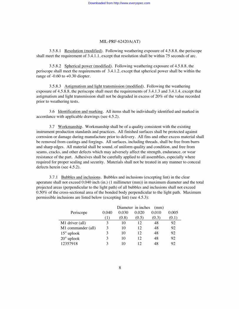
3.7.1 Bubbles and inclusions. Bubbles and inclusions (excepting lint) in the clearaperature shall not exceed 0.040 inch (in.) (1 millimeter (mm)) in maximum diameter and the totalprojected areas (perpendicular to the light path) of all bubbles and inclusions shall not exceed0.50% of the cross-sectional area of the bonded body perpendicular to the light path. Maximumpermissible inclusions are listed below (excepting lint) (see 4.5.3):
Diameter in inches (mm)Periscope 0.040
(1)0.030(0.8)
0.020(0.5)
0.010(0.3)
0.005(0.1)
M1 driver (all) 3 10 12 48 92M1 commander (all) 3 10 12 48 9215° uplook 3 10 12 48 9220° uplook 3 10 12 48 9212357918 3 10 12 48 92
Downloaded from http://www.everyspec.com
MIL-PRF-62420A(AT)
9
Diameter in inches (mm)Periscope 0.040
(1)0.030(0.8)
0.020(0.5)
0.010(0.3)
0.005(0.1)
12357792, 12357794 5 10 21 81 33212357850, 1237003312370322, 12370393
More than the maximum combination of bubbles and inclusions shall not be permitted although alesser number than permissible is found in one area.
3.7.2 Lint. No lint particles in the clear aperature shall exceed 0.25 in. (6.4 mm) inprojected length (perpendicular to the light path). Not more than one such lint particle shall bepermitted. No additional lint particles shall exceed 0.125 in. (3.2 mm) in projected length. Thecross-sectional area of all lint particles shall be computed on the basis of 0.003 in. (0.08 mm)width and shall be included in the computation of total projected area. The total projected length(in.) of all lint particles shall not exceed the following (see 4.5.4):
M1 short driver - 0.75 in. (19 mm)M1 wide driver - 1.35 in. (34.3 mm)M1 tall commander - 1.35 in.M1 short commander - 0.75 in.12357908, 12357909, 12357918 - 0.75 in.12357792, 12357794, 12357850, 12370033, 12370322, 12370393 - 1.35 in.
3.7.3 Cleanliness. The optical surfaces of completed instruments shall be clean and freeof condensates and volatile substances when examined in accordance with method specified in4.5.5. Dust retention grease shall not be used except with specific authorization of theresponsible technical activity.
4. VERIFICATION
4.1 Classification of inspections. The inspection requirements specified herein areclassified as follows:
a. First article inspection (see 4.3).b. Conformance inspection (CI) (see 4.4).
4.2 Inspection conditions. Unless otherwise specified (see 6.2), all inspections shall beperformed in accordance with the following conditions:
Downloaded from http://www.everyspec.com
MIL-PRF-62420A(AT)
10
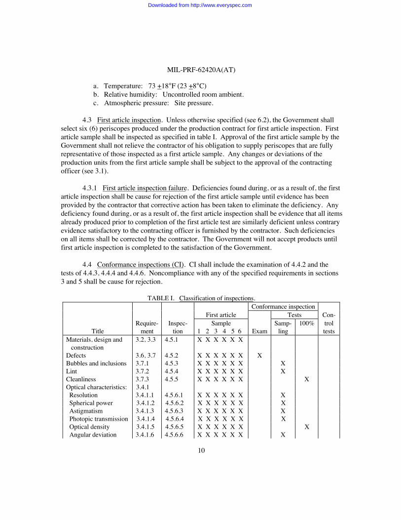
a. Temperature: 73 +18°F (23 +8°C)b. Relative humidity: Uncontrolled room ambient.c. Atmospheric pressure: Site pressure.
4.3 First article inspection. Unless otherwise specified (see 6.2), the Government shallselect six (6) periscopes produced under the production contract for first article inspection. Firstarticle sample shall be inspected as specified in table I. Approval of the first article sample by theGovernment shall not relieve the contractor of his obligation to supply periscopes that are fullyrepresentative of those inspected as a first article sample. Any changes or deviations of theproduction units from the first article sample shall be subject to the approval of the contractingofficer (see 3.1).
4.3.1 First article inspection failure. Deficiencies found during, or as a result of, the firstarticle inspection shall be cause for rejection of the first article sample until evidence has beenprovided by the contractor that corrective action has been taken to eliminate the deficiency. Anydeficiency found during, or as a result of, the first article inspection shall be evidence that all itemsalready produced prior to completion of the first article test are similarly deficient unless contraryevidence satisfactory to the contracting officer is furnished by the contractor. Such deficiencieson all items shall be corrected by the contractor. The Government will not accept products untilfirst article inspection is completed to the satisfaction of the Government.
4.4 Conformance inspections (CI). CI shall include the examination of 4.4.2 and thetests of 4.4.3, 4.4.4 and 4.4.6. Noncompliance with any of the specified requirements in sections3 and 5 shall be cause for rejection.
TABLE I. Classification of inspections.Conformance inspection
First article Tests Con-
TitleRequire-
mentInspec-
tionSample
1 2 3 4 5 6 ExamSamp-
ling100% trol
testsMaterials, design and construction
3.2, 3.3 4.5.1 X X X X X X
Defects 3.6, 3.7 4.5.2 X X X X X X XBubbles and inclusions 3.7.1 4.5.3 X X X X X X XLint 3.7.2 4.5.4 X X X X X X XCleanliness 3.7.3 4.5.5 X X X X X X XOptical characteristics: 3.4.1 Resolution 3.4.1.1 4.5.6.1 X X X X X X X Spherical power 3.4.1.2 4.5.6.2 X X X X X X X Astigmatism 3.4.1.3 4.5.6.3 X X X X X X X Photopic transmission 3.4.1.4 4.5.6.4 X X X X X X X Optical density 3.4.1.5 4.5.6.5 X X X X X X X Angular deviation 3.4.1.6 4.5.6.6 X X X X X X X
Downloaded from http://www.everyspec.com
MIL-PRF-62420A(AT)
11
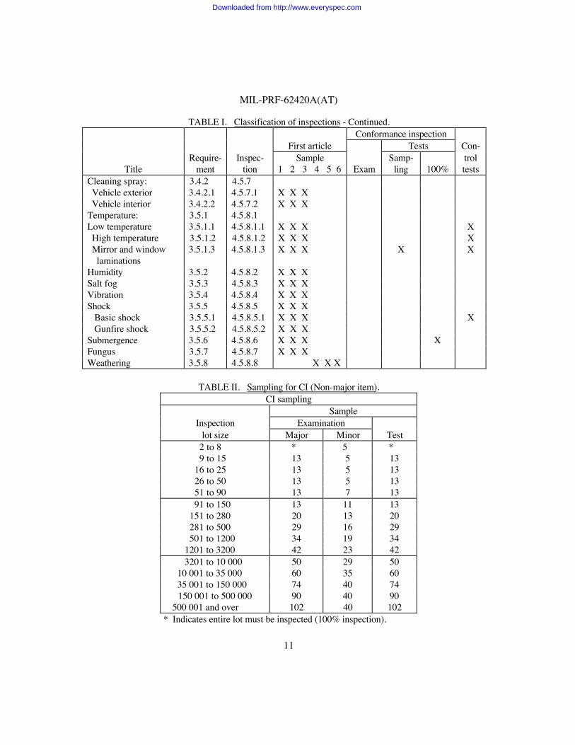
TABLE I. Classification of inspections - Continued.Conformance inspection
First article Tests Con-
TitleRequire-
mentInspec-
tionSample
1 2 3 4 5 6 ExamSamp-
ling 100%troltests
Cleaning spray: 3.4.2 4.5.7 Vehicle exterior 3.4.2.1 4.5.7.1 X X X Vehicle interior 3.4.2.2 4.5.7.2 X X XTemperature: 3.5.1 4.5.8.1Low temperature 3.5.1.1 4.5.8.1.1 X X X X High temperature 3.5.1.2 4.5.8.1.2 X X X X Mirror and window laminations
3.5.1.3 4.5.8.1.3 X X X X X
Humidity 3.5.2 4.5.8.2 X X XSalt fog 3.5.3 4.5.8.3 X X XVibration 3.5.4 4.5.8.4 X X XShock 3.5.5 4.5.8.5 X X X Basic shock 3.5.5.1 4.5.8.5.1 X X X X Gunfire shock 3.5.5.2 4.5.8.5.2 X X XSubmergence 3.5.6 4.5.8.6 X X X XFungus 3.5.7 4.5.8.7 X X XWeathering 3.5.8 4.5.8.8 X X X
TABLE II. Sampling for CI (Non-major item).CI sampling
SampleInspection Examination
lot size Major Minor Test 2 to 8 * 5 * 9 to 15 13 5 13 16 to 25 13 5 13 26 to 50 13 5 13 51 to 90 13 7 13 91 to 150 13 11 13 151 to 280 20 13 20 281 to 500 29 16 29 501 to 1200 34 19 34 1201 to 3200 42 23 42 3201 to 10 000 50 29 50 10 001 to 35 000 60 35 60 35 001 to 150 000 74 40 74
150 001 to 500 000 90 40 90 500 001 and over 102 40 102
* Indicates entire lot must be inspected (100% inspection).
Downloaded from http://www.everyspec.com
MIL-PRF-62420A(AT)
12
4.4.1 Sampling inspection. Unless otherwise specified (see 6.2), the sampling inspectionspecified herein shall be used (see table II).
4.4.1.1 Lot formation. An inspection lot shall consist of all periscopes of a single type,class, style and part identification number (PIN), from an identifiable production period, from onemanufacturer, from one manufacturing location, submitted at the same time for acceptance.
4.4.1.2 Sample. The sample for CI examination and tests shall be randomly selectedfrom the inspection lot in accordance with table II.
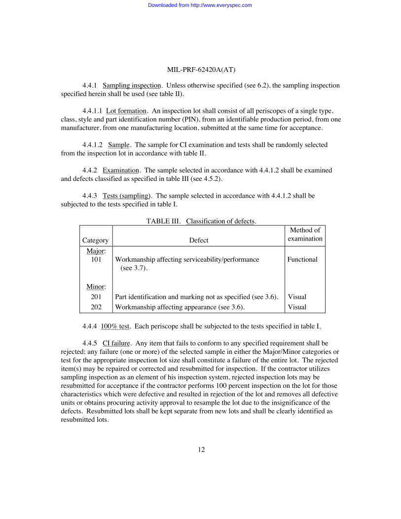
4.4.2 Examination. The sample selected in accordance with 4.4.1.2 shall be examinedand defects classified as specified in table III (see 4.5.2).
4.4.3 Tests (sampling). The sample selected in accordance with 4.4.1.2 shall besubjected to the tests specified in table I.
TABLE III. Classification of defects.
Category DefectMethod of
examination
Major:101 Workmanship affecting serviceability/performance
(see 3.7).Functional
Minor:201 Part identification and marking not as specified (see 3.6). Visual202 Workmanship affecting appearance (see 3.6). Visual
4.4.4 100% test. Each periscope shall be subjected to the tests specified in table I.
4.4.5 CI failure. Any item that fails to conform to any specified requirement shall berejected; any failure (one or more) of the selected sample in either the Major/Minor categories ortest for the appropriate inspection lot size shall constitute a failure of the entire lot. The rejecteditem(s) may be repaired or corrected and resubmitted for inspection. If the contractor utilizessampling inspection as an element of his inspection system, rejected inspection lots may beresubmitted for acceptance if the contractor performs 100 percent inspection on the lot for thosecharacteristics which were defective and resulted in rejection of the lot and removes all defectiveunits or obtains procuring activity approval to resample the lot due to the insignificance of thedefects. Resubmitted lots shall be kept separate from new lots and shall be clearly identified asresubmitted lots.
Downloaded from http://www.everyspec.com
MIL-PRF-62420A(AT)
13
4.4.6 Control tests. Control tests shall be conducted on one periscope per five hundredunits consecutively produced or once in ninety (90) days, whichever comes first. Not more thanone test shall be performed in a ninety day period, unless there is a control test failure.
4.4.6.1 Control test failure. Failure of any periscope to pass any of the specified controltests shall be cause for the Government to refuse acceptance of the production quantityrepresented, until action taken by the contractor to correct defects and prevent recurrence hasbeen approved by the Government.
4.5 Methods of inspection.
4.5.1 Materials, design and construction. Conformance to 3.2 and 3.3 shall bedetermined by inspection of contractor records providing proof or certification that design,construction, processing, and materials conform to requirements. Applicable records shall includedrawings, specifications, design data, receiving inspection records, processing and quality controlstandards, vendor catalogs and certifications, industry standards, test reports, and rating data.
4.5.2 Defects. Conformance to 3.6 and 3.7 shall be determined by examination for thedefects listed in table III. Examination shall be visual, tactile, or by measurement with standardinspection equipment.
4.5.3 Bubbles and inclusions. To determine conformance to 3.7.1, periscopes shall beinspected for bubbles and inclusions under brilliant illumination such as outlined in 4.5.6. Thedistribution and size of bubbles and inclusions shall conform to 3.7.1.
4.5.4 Lint. To determine conformance to 3.7.2, the test for lint shall be performed on theperiscopes at the same time that the test for bubbles and inclusions, 4.5.3, is being performed. The length of the lint particles shall conform to the requirements of 3.7.2. The total projectedarea of any lint particles shall be computed as stated in 3.7.2 and shall be added to the total areafound in 4.5.3. The periscopes shall be inspected in accordance with 4.5.6.
4.5.5 Cleanliness. To determine conformance to 3.7.3, each optical system exit andentrance window exterior surface shall be examined with the unaided eye.
4.5.6 Optical characteristics. The test to determine compliance with mirror and windowlaminations, lint, bubbles and inclusions shall be made by viewing the periscope through the exit,or entrance, window against a uniformly illuminated translucent ground glass field (or equivalent)having a brightness of approximately 300 foot candles.
4.5.6.1 Resolution. The test to determine compliance with the resolution, sphericalpower, and astigmatism requirements of 3.4.1.1, 3.4.1.2 and 3.4.1.3, respectively, shall beperformed utilizing a holding medium to support the periscope during the test, a diopter with a
Downloaded from http://www.everyspec.com
MIL-PRF-62420A(AT)
14
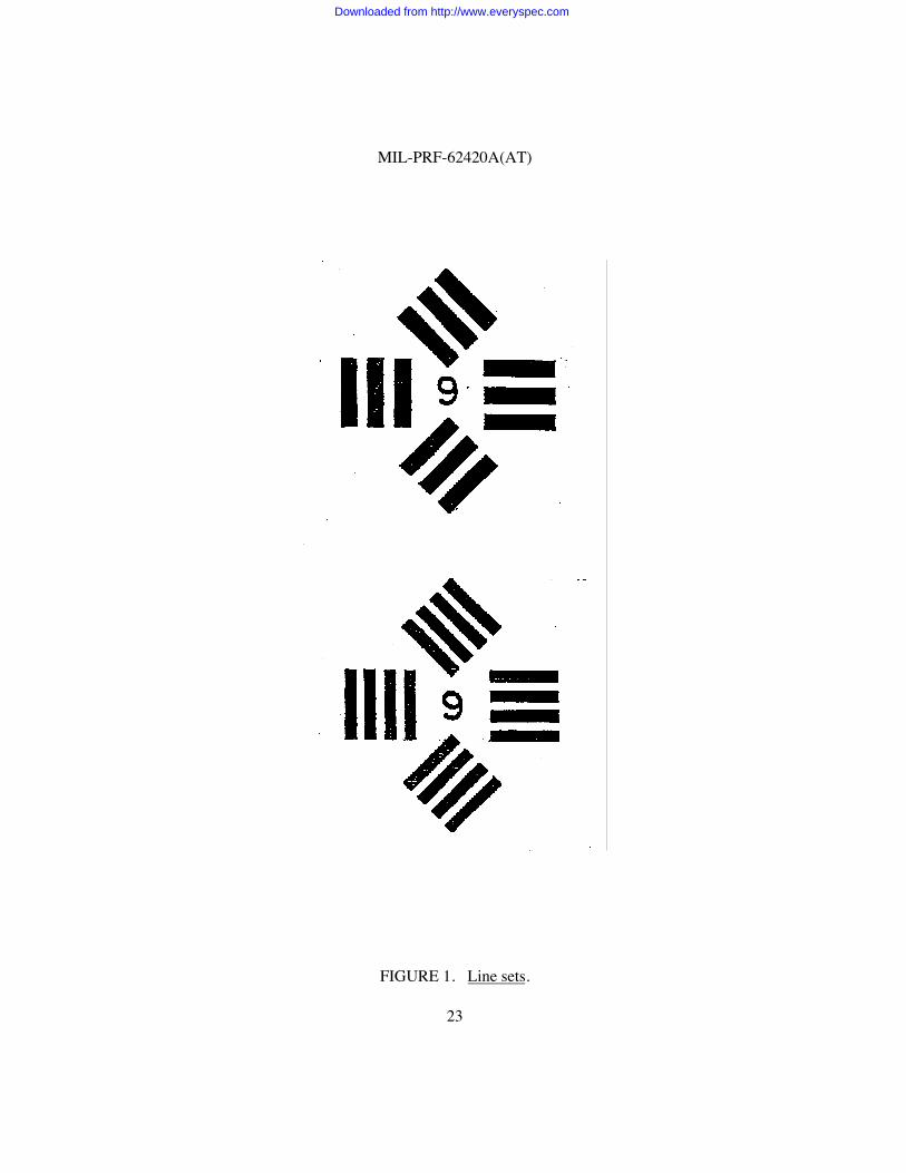
magnification of at least three power (3x) and a resolving power chart. The resolving power chartshall represent the angular subtense for the seconds of arc specified in 3.4.1.1, and shall containfour line sets as shown in figure 1. The chart of appropriate dimensions may be located in acollimator or it may be viewed directly. The diopter’s eyepiece shall be focused to its reticle toaccommodate the individual inspector’s eye. Using the diopter, the target shall be resolved ineach of the four meridians, and the diopter for each meridian shall be recorded. This operationshall be repeated in nine regions of the clear aperture, three readings approximately 1.5 in.(38 mm) from each end and three readings in the center. The total spread of the four readingsobtained in each of the nine areas shall not exceed 0.25 diopter.
4.5.6.2 Spherical power. The average of the horizontal and vertical target focus readingsobtained in each of the nine areas, as outlined in 4.5.6.1, shall be in accordance with the sphericalpower requirement of 3.4.1.2.
4.5.6.3 Astigmatism. The algebraic difference in focus between the horizontal andvertical target focus readings obtained in each of the nine areas, as outlined in 4.5.6.1, shall be inaccordance with the astigmatism requirement of 3.4.1.3.
4.5.6.4 Photopic transmission (PT) measurement. To determine conformance to 3.4.1.4,the periscope shall be measured at 0 +2 degrees incidence and shall be tested in accordance withthe following:
a. Apparatus. One of the following systems shall be utilized:
(1) A constant current tungsten lampA monochromatorA detector
(2) A double beam spectrophotometer(3) A Pritchard type photometer
b. Measurement. The preferred wavelength range for this measurement is 380 nanometer (nm) to 760 nm: any range that includes the range 400 nm to 700 nm is acceptable. Photopic transmission shall be derived from multiplyingmeasured spectral transmission data, taken every 5 nm at 0 +2 degrees incidencealong the optical axis of the periscope, by the photopic luminous efficiency valuesthat make up the standard human eye curve established by the CommissionInternationale del’Eclair (CIE) (see ASTM E308).
Downloaded from http://www.everyspec.com
MIL-PRF-62420A(AT)
15
c. Calculation.
The PT is derived from:
760 760
X = ∑ T(w) S(w)V(w)dw Y = ∑ S(w) V(w) dw 380 380
PT = x/y
Where,
w = WavelengthT(w) = Filter transmission characteristicsS(w) = CIE source A characteristic (1931)V(w) = Photopic visibility function (1931)dw = 5 nm intervals
4.5.6.5 Optical density measurement using a spectrophotometer. To determineconformance to 3.4.1.5, the periscope shall be measured at 0 +2 degrees incidence and shall betested in accordance with the following:
a. Apparatus. One of the following systems shall be used:
(1) A constant current tungsten lampA monochromatorA detector
(2) A double beam spectrophotometer
For either system, the light incident on the periscope shall have a collimated beam diameter of10 +3 mm (1/e2) and the system shall be calibrated over the optical density range of 3 through 4using neutral density filters traceable to the National Institute of Standards and Technology(NIST). Prior to testing, system alignment shall be verified by measuring the periscope’stransmission or optical density at an unattenuated wavelength (approximate range 500-550 nm).
b. Calculations.
(1) Transmission (T) at each wavelength is:
T = Radiance with the periscope in the optical train Radiance without periscope in optical train
Downloaded from http://www.everyspec.com
MIL-PRF-62420A(AT)
16
(2) The optical density (O.D.) is:O.D. = log (1/T)
4.5.6.6 Angular deviation. To determine conformance to 3.4.1.6 and the applicabledrawing, the periscope shall be mounted vertically and shall be viewed through the exit windowwith an observation telescope placed normal to the exit window and equipped with acentercross-hair reticule. Horizontal lines on a wall chart shall be viewed representing the upperand lower angular deviation limits. The observed cross hair must fall between the upper andlower deviation limits. Alternate method (1): a light collimator can be used in place of the wallchart. Alternate method (2): a hene laser can be used in place of the observation telescope.
4.5.7 Cleaning spray.
4.5.7.1 Vehicle exterior cleaning spray. To determine conformance to 3.4.2.1, theportion of the assembly above the sealing surface shall be exposed to a water jet or stream sprayusing high grade commercial cleaning agents that meet the environmental and performancerequirements of this specification. The jet shall be applied perpendicular to and at a distance nocloser than one ft (30.5 centimeter (cm)) nor farther than 2 ft (61 cm) from the component surfaceat a cleaning rate of 1 square foot per minute (ft2/min) (0.093 square meter per minute (m2/min))for a period of 10 minutes. The water jet shall be derived from a nozzle having an orificediameter of 0.25 in. (0.6 cm) and a nozzle pressure of 110 pounds per square inch gage (psig)(758 kPa). The periscope shall immediately be followed by a cold water rinse and air dried andsubsequently shall be subjected to the performance tests of 3.4.1.
4.5.7.2 Vehicle interior cleaning spray. To determine conformance to 3.4.2.2, theportion of the assembly below the sealing surface shall be exposed to a jet spray of tap waterapplied perpendicular to and at a distance no closer than one foot nor farther than 2 ft from thecomponent surface at a cleaning rate of 1 ft2/min for a period of 10 minutes. The water jet shallbe derived from a nozzle having an orifice diameter of 0.25 in. and a nozzle pressure of not morethan 25 psig (172 kPa). After the periscope has been air dried, the assembly shall be subjected tothe performance tests of 3.4.1.
4.5.8 Environmental. Unless otherwise specified herein, the applicable test methods andprocedures of MIL-STD-810 shall apply (see 3.5). Note that the optical performance tests of3.4.1 shall be performed after completing the required series of environmental tests. Conductingoptical performance tests between environmental tests is optional.
4.5.8.1 Temperature.
4.5.8.1.1 Low temperature. To determine conformance with 3.5.1.1, the periscope shallbe placed in a temperature chamber and subjected to the low temperature test as specified in
Downloaded from http://www.everyspec.com
MIL-PRF-62420A(AT)
17
MIL-STD-810, method 502.3, procedure I. A temperature of -65 degrees Fahrenheit (°F)(-54 degrees Celsius (°C)) shall be maintained for a period of 24 hours. At the conclusion of thistime, the unit shall be returned to 73 +18°F (23 +8°C). The unit shall show no indication ofmoisture buildup, bond separation or other forms of image degradation and shall meet therequirements of 3.5.1.3. The periscope shall then be tested per 4.5.6.1, 4.5.6.4, 4.5.6.5and 4.5.8.6.
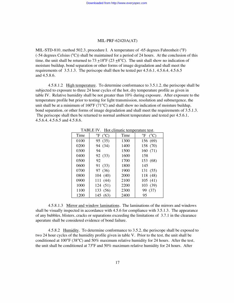
4.5.8.1.2 High temperature. To determine conformance to 3.5.1.2, the periscope shall besubjected to exposure to three 24 hour cycles of the hot, dry temperature profile as given intable IV. Relative humidity shall be not greater than 10% during exposure. After exposure to thetemperature profile but prior to testing for light transmission, resolution and submergence, theunit shall be at a minimum of 160°F (71°C) and shall show no indication of moisture buildup,bond separation, or other forms of image degradation and shall meet the requirements of 3.5.1.3. The periscope shall then be returned to normal ambient temperature and tested per 4.5.6.1,4.5.6.4, 4.5.6.5 and 4.5.8.6.
TABLE IV. Hot climatic temperature test.Time °F (°C) Time °F (°C)0100 95 (35) 1300 156 (69)0200 94 (34) 1400 158 (70)0300 94 1500 160 (71)0400 92 (33) 1600 158 0500 92 1700 153 (68)0600 91 (33) 1800 145 0700 97 (36) 1900 131 (55)0800 104 (40) 2000 118 (48)0900 111 (44) 2100 105 (41)1000 124 (51) 2200 103 (39)1100 133 (56) 2300 99 (37)1200 145 (63) 2400 95
4.5.8.1.3 Mirror and window laminations. The laminations of the mirrors and windowsshall be visually inspected in accordance with 4.5.6 for compliance with 3.5.1.3. The appearanceof any bubbles, blisters, cracks or separations exceeding the limitations of 3.7.1 in the clearanceaperature shall be considered evidence of bond failure.
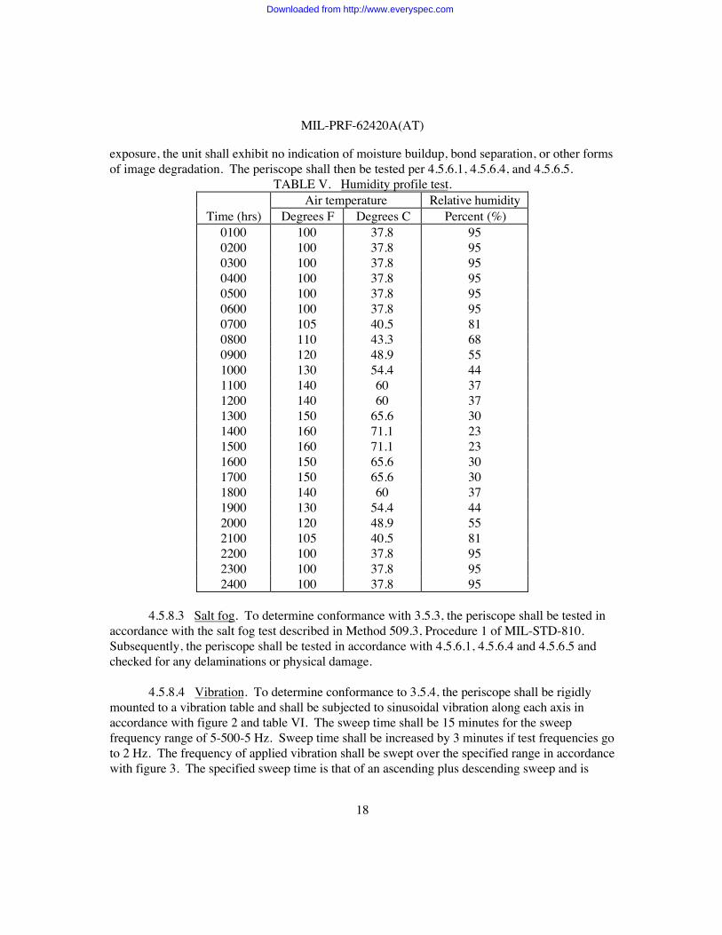
4.5.8.2 Humidity. To determine conformance to 3.5.2, the periscope shall be exposed totwo 24 hour cycles of the humidity profile given in table V. Prior to the test, the unit shall beconditioned at 100°F (38°C) and 50% maximum relative humidity for 24 hours. After the test,the unit shall be conditioned at 73°F and 50% maximum relative humidity for 24 hours. After
Downloaded from http://www.everyspec.com
MIL-PRF-62420A(AT)
18
exposure, the unit shall exhibit no indication of moisture buildup, bond separation, or other formsof image degradation. The periscope shall then be tested per 4.5.6.1, 4.5.6.4, and 4.5.6.5.
TABLE V. Humidity profile test.Air temperature Relative humidity
Time (hrs) Degrees F Degrees C Percent (%)0100 100 37.8 950200 100 37.8 950300 100 37.8 950400 100 37.8 950500 100 37.8 950600 100 37.8 950700 105 40.5 810800 110 43.3 680900 120 48.9 551000 130 54.4 441100 140 60 371200 140 60 371300 150 65.6 301400 160 71.1 231500 160 71.1 231600 150 65.6 301700 150 65.6 301800 140 60 371900 130 54.4 442000 120 48.9 552100 105 40.5 812200 100 37.8 952300 100 37.8 952400 100 37.8 95
4.5.8.3 Salt fog. To determine conformance with 3.5.3, the periscope shall be tested inaccordance with the salt fog test described in Method 509.3, Procedure 1 of MIL-STD-810. Subsequently, the periscope shall be tested in accordance with 4.5.6.1, 4.5.6.4 and 4.5.6.5 andchecked for any delaminations or physical damage.
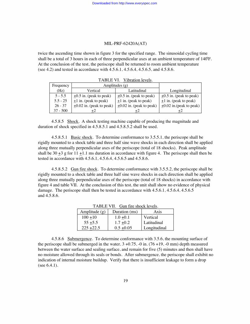
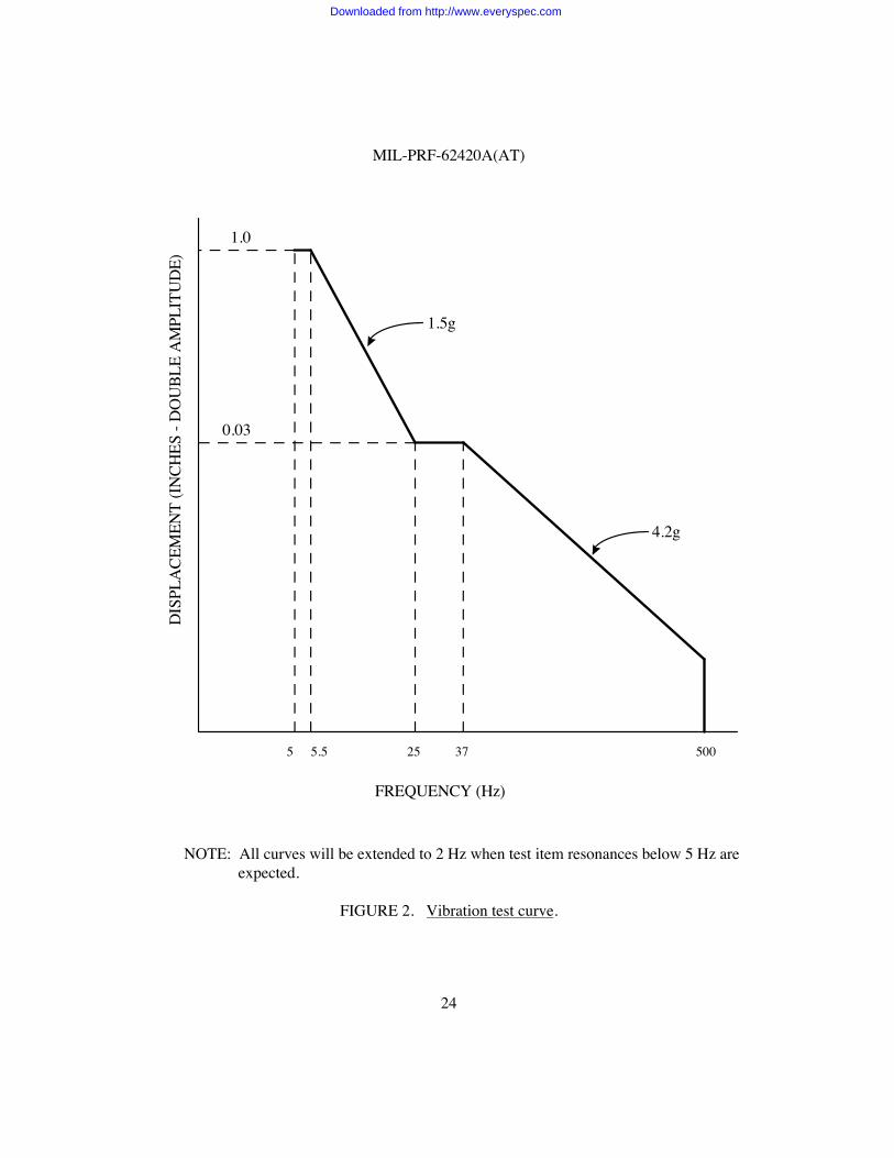
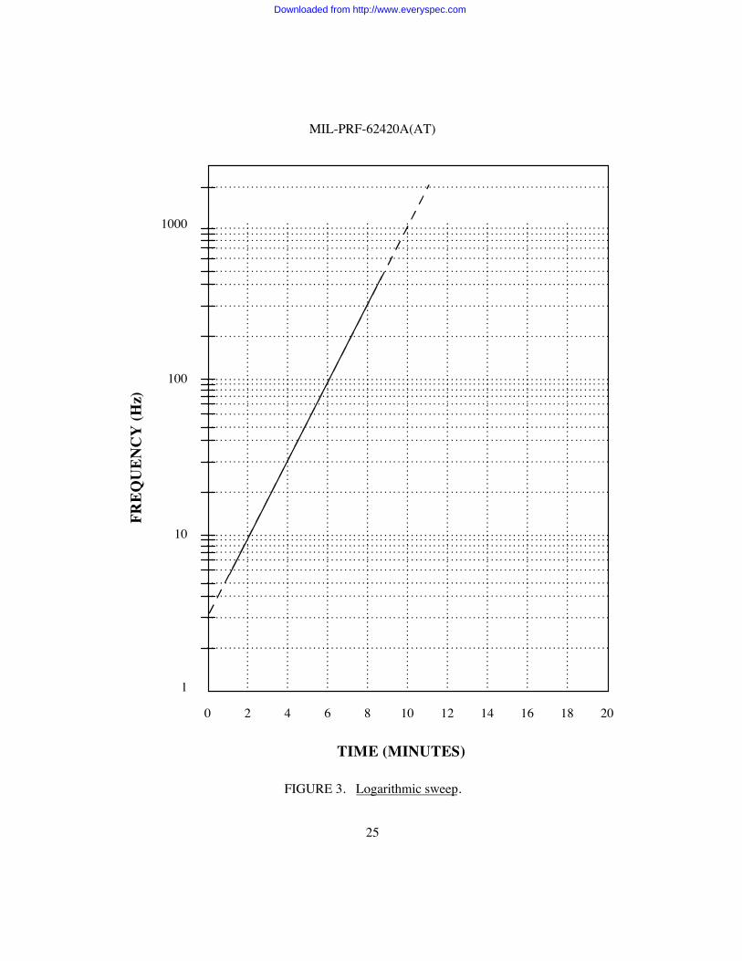
4.5.8.4 Vibration. To determine conformance to 3.5.4, the periscope shall be rigidlymounted to a vibration table and shall be subjected to sinusoidal vibration along each axis inaccordance with figure 2 and table VI. The sweep time shall be 15 minutes for the sweepfrequency range of 5-500-5 Hz. Sweep time shall be increased by 3 minutes if test frequencies goto 2 Hz. The frequency of applied vibration shall be swept over the specified range in accordancewith figure 3. The specified sweep time is that of an ascending plus descending sweep and is
Downloaded from http://www.everyspec.com
MIL-PRF-62420A(AT)
19
twice the ascending time shown in figure 3 for the specified range. The sinusoidal cycling timeshall be a total of 3 hours in each of three perpendicular axes at an ambient temperature of 140°F.At the conclusion of the test, the periscope shall be returned to room ambient temperature(see 4.2) and tested in accordance with 4.5.6.1, 4.5.6.4, 4.5.6.5, and 4.5.8.6.
TABLE VI. Vibration levels.Frequency Amplitudes (g)
(Hz) Vertical Latitudinal Longitudinal5 - 5.5 +0.5 in. (peak to peak) +0.5 in. (peak to peak) +0.5 in. (peak to peak)5.5 - 25 +1 in. (peak to peak) +1 in. (peak to peak) +1 in. (peak to peak)26 - 37 +0.02 in. (peak to peak) +0.02 in. (peak to peak) +0.02 in.(peak to peak)
37 - 500 +2 +2 +2
4.5.8.5 Shock. A shock testing machine capable of producing the magnitude andduration of shock specified in 4.5.8.5.1 and 4.5.8.5.2 shall be used.
4.5.8.5.1 Basic shock. To determine conformance to 3.5.5.1, the periscope shall berigidly mounted to a shock table and three half sine wave shocks in each direction shall be appliedalong three mutually perpendicular axes of the periscope (total of 18 shocks). Peak amplitudeshall be 30 +3 g for 11 +1.1 ms duration in accordance with figure 4. The periscope shall then betested in accordance with 4.5.6.1, 4.5.6.4, 4.5.6.5 and 4.5.8.6.
4.5.8.5.2 Gun fire shock. To determine conformance with 3.5.5.2, the periscope shall berigidly mounted to a shock table and three half sine wave shocks in each direction shall be appliedalong three mutually perpendicular axes of the periscope (total of 18 shocks) in accordance withfigure 4 and table VII. At the conclusion of this test, the unit shall show no evidence of physicaldamage. The periscope shall then be tested in accordance with 4.5.6.1, 4.5.6.4, 4.5.6.5and 4.5.8.6.
TABLE VII. Gun fire shock levels.Amplitude (g) Duration (ms) Axis 100 +10 1.0 +0.1 Vertical 55 +5.5 1.7 +0.2 Latitudinal 225 +22.5 0.5 +0.05 Longitudinal
4.5.8.6 Submergence. To determine conformance with 3.5.6, the mounting surface ofthe periscope shall be submerged in the water, 3 +0.75, -0 in. (76 +19, -0 mm) depth measuredbetween the water surface and sealing surface, and remain for five (5) minutes and then shall haveno moisture allowed through its seals or bonds. After submergence, the periscope shall exhibit noindication of internal moisture buildup. Verify that there is insufficient leakage to form a drop(see 6.4.1).
Downloaded from http://www.everyspec.com
MIL-PRF-62420A(AT)
20
4.5.8.7 Fungus. To determine conformance to 3.5.7, the periscope shall be tested inaccordance with MIL-STD-810, Method 508.4, except that after inoculation the periscope shallbe exposed to ambient air temperatures of 80 to 84°F (27 to 29°C) at relative humidity between96 to 100% for a 28 day duration. In lieu of the performance of MIL-STD-810 fungus test, acertificate of compliance with supporting data maybe provided attesting that the assembly isconstructed of materials that will not support fungal growth (see 6.2).
4.5.8.8 Weathering test. This test shall be conducted upon completion of all the othertests specified in 4.5.8 through 4.5.9.7. The periscope shall be subject to the environmentalconditions and the weathering tests specified below, the test cycle shall be approved by theacquisitioning activity prior to test initiation. The periscope shall show no evidence of failure andshall meet the requirements of 3.5.8.1, 3.5.8.2, 3.5.8.3, 3.4.1.5, and 3.5.1.3, when retested inaccordance with 4.5.6.1 (modified), 4.5.6.2 (modified), 4.5.6.3 (modified), optical density 4.5.6.5,and mirror and window lamination 4.5.8.1.3.
a. No less than 350 hours of simulated sunshine. Heat intensity shall be 160 +5°F(71 +2°C) at the geometric center of the periscope. The spectral energydistribution of simulated sunshine shall be in accordance with method 505.3 ofMIL-STD-810.
b. No less than 420 hours steady state hot-humid exposure at 110 +10°F(43 +6°C) relative humidity 70 +10%.
c. No less than 420 hours of cold exposure at 20 +5°F (-7 +4°C).d. Simulated sunshine shall include ultraviolet and be cycled in accordance with
Method 505.3, Procedure 1 of MIL-STD-810 except the diurnal cycle hot-drytemperature shall have a peak temperature of 160 +5°F at the geometric center ofthe periscope. Heat intensity shall be controlled by adjustment of the light sourceto periscope distance and shall not be achieved by varying voltage to the source.
e. Environmental conditions a and b shall be cycled so that conditions shall notexceed 10 hours duration, and condition c shall be maintained for minimum of 72 continuous hours.
f. No test exposure shall be followed by a like exposure. For the duration of thetest, the periscope shall be exposed to air, the test chamber, ozone and shall notbe purged with any inert gas.
4.5.8.9 Chemicals. To determine conformance to 3.4.3, the assembly shall be exposed tothe vapors of and direct contact with the chemicals specified in 3.4.3 for a period of 48 hoursminimum. The periscope to be tested shall be placed on an open rack suspended in a sealedcontainer. Prior to closure of the container each chemical shall be successively sprayed onto allexterior surfaces in sufficient volume to begin run off. The container will be sealed for 48 hoursminimum. After exposure the assembly shall be subjected to the performance tests of 3.4.1.
Downloaded from http://www.everyspec.com
MIL-PRF-62420A(AT)
21
5. PACKAGING
5.1 Packaging. For acquisition purposes, the packaging requirements shall be asspecified in the contract or order (see 6.2). When actual packaging of materiel is to be performedby DoD personnel, these personnel need to contact the responsible packaging activity to ascertainrequisite packaging requirements. Packaging requirements are maintained by the InventoryControl Point’s packaging activity within the Military Department or Defense Agency, or withinthe Military Department’s System Command. Packaging data retrieval is available from themanaging Military Department’s or Defense Agency’s automated packaging files, CD-ROMproducts, or by contacting the responsible packaging activity.
6. NOTES
(This section contains information of a general or explanatory nature which may behelpful, but is not mandatory.)
6.1 Intended use. Periscopes covered by this specification are intended for use as unityvision devices in combat type vehicles.
6.2 Acquisition requirements. Acquisition documents must specify the following:
a. Title, number, and date of this specification.b. Classification (see 1.2).c. Issue of DoDISS to be cited in the solicitation, and if required, the specific issue of
individual documents referenced (see 2.2.1 and 2.3).d. If first article is required (see 3.1).e. Item name and drawing number (see 3.3).f. If other inspection conditions are required (see 4.2).g. If first article inspection is required (see 4.3).h. If sampling inspection other than table III should be used (see 4.4.1).i. If a certificate of compliance may be substituted for fungus testing (see 4.5.8.7).j. Packaging requirements (see 5.1).
6.3 Part identification number (PIN). The PINs to be used for periscopes acquired tothis specification are created as follows:
Downloaded from http://www.everyspec.com
MIL-PRF-62420A(AT)
22
M 62420 - X
Dash number indicating item (see 1.2)(Example: M62420-1 (Periscope, tank: M27E4))
Specification number
Prefix
6.4 Definitions.
6.4.1 Leaks. The following definitions for leaks apply (see 4.5.8.6):
a. Weep: Any non-recurring evidence of fluid beyond the seal or joint.b. Seep: Any recurring evidence of fluid beyond the seal or joint that results in
an accumulation of more than 0.05 cm2 volume.c. Droplet: Any recurring evidence of fluid beyond the seal or joint that results in
an accumulation of more than 0.05 cm2 volume that does not fall.d. Drop: A drop is defined as a volume of 0.05 cm2.e. Drip: Any recurring evidence of fluid beyond the seal or joint where a droplet
or more forms and falls.
6.5 Subject term (key word) listing.
Light (photopic) transmissionOptical densityPhotopic (light) transmissionResolutionSpherical powerUnity periscope
6.6 Changes from previous issue. Marginal notations are not used in this revision toidentify changes with respect to the previous issue due to the extent of the changes.
Downloaded from http://www.everyspec.com
MIL-PRF-62420A(AT)
23
FIGURE 1. Line sets.
Downloaded from http://www.everyspec.com
MIL-PRF-62420A(AT)
24
5 5.5 25 37 500
4.2g
1.5g
1.0
0.03
DIS
PLA
CEM
ENT
(INCH
ES -
DO
UBL
E A
MPL
ITU
DE)
FREQUENCY (Hz)
NOTE: All curves will be extended to 2 Hz when test item resonances below 5 Hz areexpected.
FIGURE 2. Vibration test curve.
Downloaded from http://www.everyspec.com
MIL-PRF-62420A(AT)
25
1
10
100
1000
0 8
TIME (MINUTES)
FREQ
UEN
CY
(Hz)
2 4 6 10 12 14 16 18 20
FIGURE 3. Logarithmic sweep.
Downloaded from http://www.everyspec.com
MIL-PRF-62420A(AT)
26
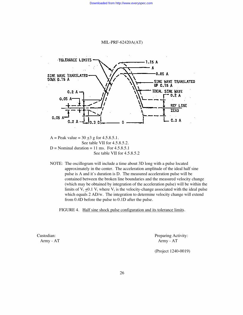
A = Peak value = 30 +3 g for 4.5.8.5.1. See table VII for 4.5.8.5.2.
D = Nominal duration = 11 ms. For 4.5.8.5.1 See table VII for 4.5.8.5.2
NOTE: The oscillogram will include a time about 3D long with a pulse locatedapproximately in the center. The acceleration amplitude of the ideal half sinepulse is A and it’s duration is D. The measured acceleration pulse will becontained between the broken line boundaries and the measured velocity change(which may be obtained by integration of the acceleration pulse) will be within thelimits of Vi +0.1 Vi where Vi is the velocity-change associated with the ideal pulsewhich equals 2 AD/w. The integration to determine velocity change will extendfrom 0.4D before the pulse to 0.1D after the pulse.
FIGURE 4. Half sine shock pulse configuration and its tolerance limits.
Custodian: Preparing Activity: Army - AT Army - AT
(Project 1240-0019)
Downloaded from http://www.everyspec.com
Downloaded from http://www.everyspec.com

![INCH-POUND MIL-PRF-13830B MIL-O-13830A PERFORMANCE …1].pdf · 2014-06-25 · INCH-POUND MIL-PRF-13830B 9 January 1997 SUPERSEDING MIL-O-13830A 11 September 1963 PERFORMANCE SPECIFICATION](https://img.pdfslide.us/doc/110x75/5e75eb76c9119c2b723b9b90/inch-pound-mil-prf-13830b-mil-o-13830a-performance-1pdf-2014-06-25-inch-pound.jpg)