Embed Size (px)
Citation preview
INCH-POUND MIL-DTL-32496
08 APRIL 2014
DETAIL SPECIFICATION GENERATOR SETS, SKID MOUNTED, TRAILER MOUNTED
ADVANCED MEDIUM-SIZED MOBILE POWER SOURCES, TACTICAL DIESEL FUEL DRIVEN, ALTERNATING CURRENT
5 through 60 KILOWATTS
GENERAL SPECIFICATION FOR
This specification is approved for use within US Army Research Development and Engineering Command, Communications and Electronics Research and Development Center, Product Realization Directorate, Department of the Army and is available for use by all Departments and Agencies of the Department of Defense.
1. SCOPE
1.1 Scope. This specification covers the general requirements for Advanced Medium-Sized
Mobile Power Sources (AMMPS) generator sets (hereinafter referred to as "set" or "sets"), 5 through 60 kilowatts (kW), 50/60 – hertz (Hz) and 400 – Hz, skid mounted, trailer mounted, tactical, diesel fuel driven, alternating current.
1.2 Classification. The sets will be tactical and of the following modes and sizes:
MODE: I - 50/60 Hz II - 400 Hz
SIZE: 5 kW, MODE I and II (4.17 kW at 50 Hz)
10 kW, MODE I and II (8.3 kW at 50 Hz) 15 kW, MODE I and II (12.5 kW at 50 Hz) 30 kW, MODE I and II (25 kW at 50 Hz) 60 kW, MODE I and II (50 kW at 50 Hz)
Beneficial comments (recommendations, additions, deletions) and any pertinent data which may be of use in improving this document should be addressed to: US Army RDECOM CERDEC PRD, Attn: RDER-PRA-GS, Ft. Belvoir, VA 22060-5817 or email: [email protected]. Since contact information can change, you may want to verify the currency of this address information using the ASSIST Online database at https://assist.dla.mil. Proposal (DD Form 1426) appearing at the end of this document or by letter. AMSC N/A FSC 6115
DISTRIBUTION STATEMENT A. Approved for public release; distribution is unlimited.
1
Downloaded from http://www.everyspec.com
MIL-DTL-32496
2
1.3 Set rating. The set will be rated 0.8 power factor (PF), lagging, and may be re-connectable for the voltages:
a. 5 kW, MODE I and II
120-volt, single phase, 2 wire 120/240-volt, single phase, 3 wire 120/208-volt, 3-phase, 4 wire
b. 10 kW, MODE I and II
120-volt, single phase, 2 wire 120/240-volt, single phase, 3 wire 120/208-volt, 3-phase, 4 wire
c. 15 kW, MODE I and II
120/208-volt, 3-phase, 4 wire 240/416-volt, 3-phase, 4 wire
d. 30 kW, MODE I and II
120/208-volt, 3-phase, 4 wire 240/416-volt, 3-phase, 4 wire
e. 60 kW, MODE I and II
120/208-volt, 3-phase, 4 wire 240/416-volt, 3-phase, 4 wire
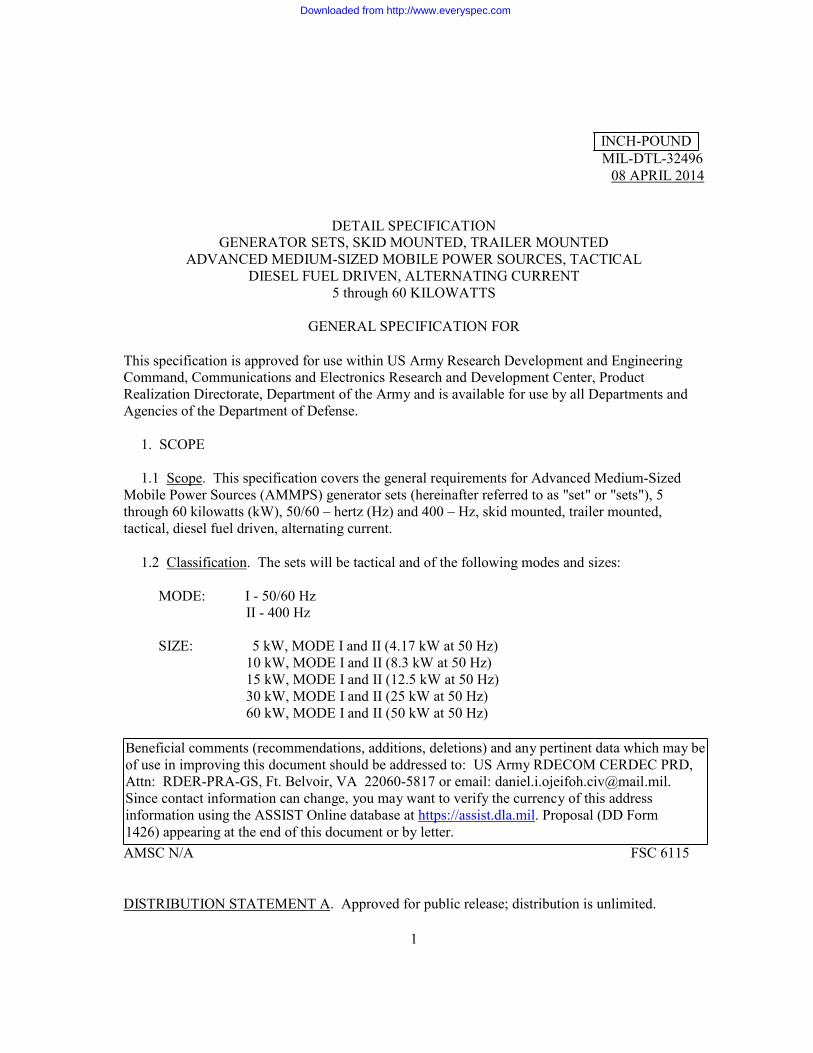
1.4 Configurations. The generator sets shall be configured as follows:
TRAILER
(IF APPLICABLE) SIZE ITEM DESCRIPTION MODEL NSN
5 kW
AMMPS 60 Hz, DED, Skid Mounted MEP-1030 N/A 6115-01-561-7329
AMMPS 400 Hz, DED, Skid Mounted MEP-1031 N/A 6115-01-561-7438
AMMPS Power Unit, 60 Hz PU-2001 Light Tactical Trailer (LTT) 6115-01-562-3992
AMMPS Power Plant, 60 Hz PP-3001 LTT 6115-01-562-3700
AMMPS Power Plant, 60 Hz PP-3101 M200A1 6115-01-562-3675 10 kW
AMMPS 60 Hz, DED, Skid Mounted MEP-1040 N/A 6115-01-561-7455
AMMPS 400 Hz, DED, Skid Mounted MEP-1041 N/A 6115-01-561-7466
AMMPS Power Unit, 60 Hz PU-2002 LTT 6115-01-562-4010
AMMPS Power Unit, 400 Hz PU-2012 LTT 6115-01-562-3907
AMMPS Power Plant, 60 Hz PP-3102 M200A1 6115-01-562-6480
Downloaded from http://www.everyspec.com
MIL-DTL-32496
3
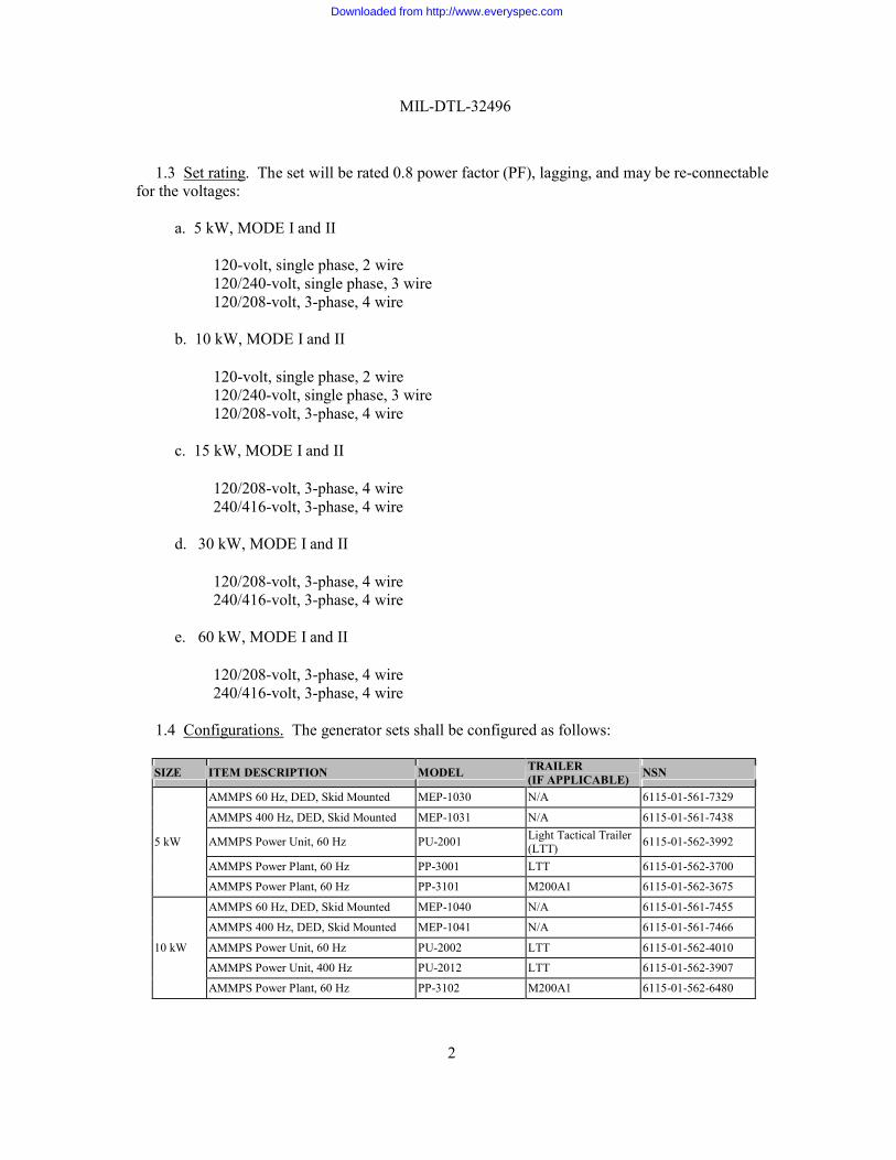
TRAILER (IF APPLICABLE)
SIZE ITEM DESCRIPTION MODEL NSN 15 kW
AMMPS 50/60 Hz, DED, Skid Mounted MEP-1050 N/A 6115-01-561-7634
AMMPS 400 Hz, DED, Skid Mounted MEP-1051 N/A 6115-01-561-7674
AMMPS Power Unit, 50/60 Hz PU-2003 LTT 6115-01-562-3721
AMMPS Power Unit, 50/60 Hz PU-2101 M200A1 6115-01-562-3689
AMMPS Power Unit, 400 Hz PU-2111 M200A1 6115-01-562-3659
AMMPS Power Plant, 400 Hz PP-3003 LTT 6115-01-562-3995 30 kW
AMMPS 50/60 Hz, DED, Skid Mounted MEP-1060 N/A 6115-01-561-7718
AMMPS 400 Hz, DED, Skid Mounted MEP-1061 N/A 6115-01-561-7738
AMMPS Power Unit, 50/60 Hz PU-2102 M200A1 6115-01-562-4106
AMMPS Power Unit, 400 Hz PU-2112 M200A1 6115-01-562-4421
AMMPS Power Unit, 50/60 Hz PU-2004* LTT NOT ASSIGNED
AMMPS Power Plant, 50/60 Hz PP-3105 M200A1 6115-01-562-4009
AMMPS Power Plant, 50/60 Hz PP-3004* LTT NOT ASSIGNED 60 kW
AMMPS 50/60 Hz, DED, Skid Mounted MEP-1070 N/A 6115-01-561-7788
AMMPS 400 Hz, DED, Skid Mounted MEP-1071 N/A 6115-01-561-7895
AMMPS Power Unit, 50/60 Hz PU-2103 M200A1 6115-01-562-4600
AMMPS Power Unit, 400 Hz PU-2113 M200A1 6115-01-562-4616
AMMPS Power Plant, 50/60 Hz PP-3106 M200A1 6115-01-562-4066
AMMPS Power Plant, 400 Hz PP-3206 M1061A1 6115-01-613-9295
AMMPS Power Plant, 50/60 Hz PP-3216 M1061A1 6115-01-613-9296
*The PU-2004 and PP-3004 are not Type-Classified or have Material Release.
2. APPLICABLE DOCUMENTS
2.1 General. The documents listed in this section are needed to meet the requirements
specified in sections 3 and 4 of this specification. This section does not include documents cited in other sections of this specification or recommended for additional information or as examples. While every effort has been made to ensure the completeness of this list, document users are cautioned that they must meet all specified requirements documents cited in sections 3 and 4 of this specification, whether or not they are listed in paragraphs 2.2 and 2.3.
2.2 Government documents.
2.2.1 Specifications, standards, and handbooks. The following specifications, standards, and
handbooks form a part of this document to the extent specified herein. Unless otherwise specified, the issues of these documents are those cited in the solicitation or contract.
SPECIFICATIONS
FEDERAL
A-A-52557 Fuel Oil, Diesel; for Posts, Camps, and Stations A-A-52624 Antifreeze, Multi Engine type
Downloaded from http://www.everyspec.com
MIL-DTL-32496
4
A-A-55804 Rod, Ground (with Attachments)
MILITARY
MIL-PRF-2104 Lubricating Oil, Internal Combustion Engine, Combat/Tactical Service
MIL-DTL-5624 Turbine Fuel, Aviation, Grades JP-4, JP-5, and JP-5/JP-8 ST MIL-PRF-10924 Grease, Automotive and Artillery
MIL-PRF-46167 Lubricating Oil, Internal Combustion Engine, Arctic MIL-A-53009 Additive, Antifreeze Extender, Liquid Cooling Systems MIL-DTL-53072 Chemical Agent Resistant Coating (CARC) System Application
Procedures and Quality Control Inspection MIL-DTL-64159 Coating, Water Dispersible Aliphatic Polyurethane, Chemical
Agent Resistant MIL-DTL-83133 Turbine Fuels, Aviation, Kerosene Types, NATO F-34 (JP-8),
NATO F-35, and JP-8 + 100 MIL-L-85762 Lighting, Aircraft, Interior, Night Vision Imaging System
(NVIS) Compatible
STANDARDS
FEDERAL
FED-STD-595 Colors Used in Government Procurement MILITARY
MIL-STD-130 Identification Marking of U.S. Military Property MIL-STD-209 Lifting and Tiedown Provisions MIL-STD-461 Requirements for the Control of Electromagnetic Interference
Characteristics of Subsystems and Equipment MIL-STD-705 Generator Sets, Engine-Driven Methods of Tests and
Instructions MIL-STD-810 Environmental Engineering Considerations and Laboratory Tests MIL-STD-882 System Safety MIL-STD-889 Dissimilar Metals
Downloaded from http://www.everyspec.com
MIL-DTL-32496
5
MIL-STD-913 Requirements for the Certification of Sling Loaded Military Equipment for External Transportation by Department of Defense Helicopters
MIL-STD-1472 Human Engineering MIL-STD-1791 Designing for Internal Aerial Delivery in Fixed Wing Aircraft MIL-STD-2169 High Altitude Electro-Magnetic Pulse (HEMP) Environment
(SECRET)
HANDBOOKS
MILITARY
MIL-HDBK-705 Generator Sets, Electrical, Measurements and Instrumentation Methods
MIL-HDBK-784 Guidelines-Design to Minimize Contamination and to Facilitate Decontamination of Military Vehicles and Other Equipment: Interiors and Exteriors
MIL-HDBK-831 Preparation of Test Reports (Unless otherwise indicated, copies of these documents are available online at http://quicksearch.dla.mil. or from the Standardization Document Order Desk, 700 Robbins Avenue, Building 4D, Philadelphia, PA 19111-5094.)
2.2.2 Other Government documents, drawings, and publications. The following Government
documents, drawings, and publications form a part of this document to the extent specified herein. Unless otherwise specified, the issues of these documents are those cited in the solicitation or contract.
2.2.2.1 Documents.
AR 750-43 Army Test, Measurement and Diagnostics Equipment (TMDE)
Program AR 700-101 Joint Operating Procedures Management and Standardization of
Mobile Electric Power Generating Sources
TOP 1-2-609, 1981 Instructional Material Adequacy Guide and Evaluation Standard
Unless otherwise indicated, copies of these documents are available on line at: www.armystudyguide.com and www.dtic.mil respectively.
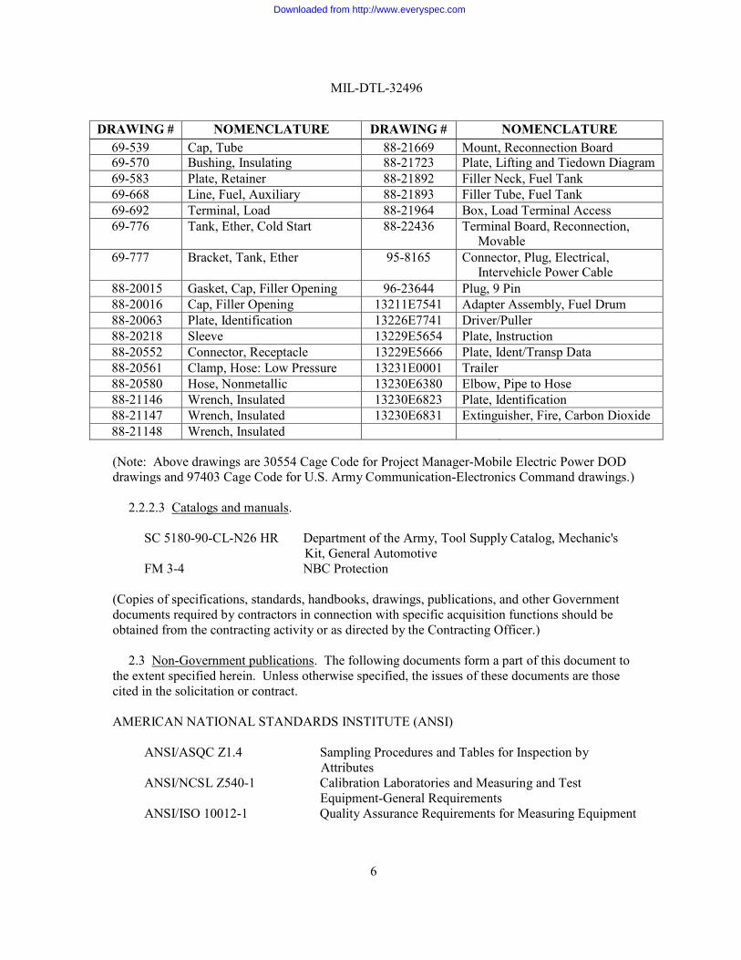
2.2.2.2 Drawings.
Downloaded from http://www.everyspec.com
MIL-DTL-32496
6
DRAWING # NOMENCLATURE DRAWING # NOMENCLATURE 69-539 Cap, Tube 88-21669 Mount, Reconnection Board 69-570 Bushing, Insulating 88-21723 Plate, Lifting and Tiedown Diagram 69-583 Plate, Retainer 88-21892 Filler Neck, Fuel Tank 69-668 Line, Fuel, Auxiliary 88-21893 Filler Tube, Fuel Tank 69-692 Terminal, Load 88-21964 Box, Load Terminal Access 69-776 Tank, Ether, Cold Start 88-22436 Terminal Board, Reconnection,
Movable 69-777 Bracket, Tank, Ether 95-8165 Connector, Plug, Electrical,
Intervehicle Power Cable 88-20015 Gasket, Cap, Filler Opening 96-23644 Plug, 9 Pin 88-20016 Cap, Filler Opening 13211E7541 Adapter Assembly, Fuel Drum 88-20063 Plate, Identification 13226E7741 Driver/Puller 88-20218 Sleeve 13229E5654 Plate, Instruction 88-20552 Connector, Receptacle 13229E5666 Plate, Ident/Transp Data 88-20561 Clamp, Hose: Low Pressure 13231E0001 Trailer 88-20580 Hose, Nonmetallic 13230E6380 Elbow, Pipe to Hose 88-21146 Wrench, Insulated 13230E6823 Plate, Identification 88-21147 Wrench, Insulated 13230E6831 Extinguisher, Fire, Carbon Dioxide 88-21148 Wrench, Insulated
(Note: Above drawings are 30554 Cage Code for Project Manager-Mobile Electric Power DOD drawings and 97403 Cage Code for U.S. Army Communication-Electronics Command drawings.)
2.2.2.3 Catalogs and manuals.
SC 5180-90-CL-N26 HR Department of the Army, Tool Supply Catalog, Mechanic's
Kit, General Automotive FM 3-4 NBC Protection
(Copies of specifications, standards, handbooks, drawings, publications, and other Government documents required by contractors in connection with specific acquisition functions should be obtained from the contracting activity or as directed by the Contracting Officer.)
2.3 Non-Government publications. The following documents form a part of this document to
the extent specified herein. Unless otherwise specified, the issues of these documents are those cited in the solicitation or contract.
AMERICAN NATIONAL STANDARDS INSTITUTE (ANSI)
ANSI/ASQC Z1.4 Sampling Procedures and Tables for Inspection by
Attributes ANSI/NCSL Z540-1 Calibration Laboratories and Measuring and Test
Equipment-General Requirements ANSI/ISO 10012-1 Quality Assurance Requirements for Measuring Equipment
Downloaded from http://www.everyspec.com
MIL-DTL-32496
7
(Application for copies should be addressed to the American National Standards Institute, 1430 Broadway, New York, NY 10018.)
INSTITUTE OF ELECTRICAL AND ELECTRONIC ENGINEERS (IEEE)
IEEE STD-315-1975 IEEE Standard Graphic Symbols for Electrical and Electronics
Diagrams (Application for copies should be addressed to the Institute of Electrical and Electronic Engineers, 445 Hoes Lane, Piscataway, NJ 08855-1331.)
NATIONAL ELECTRICAL MANUFACTURERS ASSOCIATION (NEMA)
MG1 Definite Purpose Synchronous Generators for Generating Set
Applications MG2-2001 Safety Standard and Guide for Selection, Installation, and Use of
Electric Motors and Generators (Application for copies should be addressed to the National Electrical Manufacturers Association, 2101 L Street, N.W., Washington D.C. 20037.)
NATIONAL FIRE PROTECTION ASSOCIATION (NFPA)
NFPA 70 National Electrical Code
(Application for copies should be addressed to the National Fire Protection Association, 1 Batterymarch Park, P.O. Box 9101, Quincy, MA 02269-9101.)
SOCIETY OF AUTOMOTIVE ENGINEERS, INC. (SAE)
SAE J1362 Graphical Symbols for Operator Controls and Displays on Off-Road
Self-Propelled Work Machines SAE-J2360 Lubricating Oil, Gear, Multipurpose (Metric)
(Applications for copies should be addressed to the Society of Automotive Engineers, Inc., 400 Commonwealth Drive, Warrendale, PA 15096-0001.)
UNDERWRITERS LABORATORIES INC. (UL)
UL-94HF-1 Tests for Flammability of Plastic Materials for parts in Devices and Appliances
UL-1053 Ground-Fault Sensing and Relaying Equipment UL-60950-1 Standard for Safety - Information Technology Equipment - Safety
Downloaded from http://www.everyspec.com
MIL-DTL-32496
8
(Applications for this document should be addressed to Underwriters Laboratories Inc., 1285 Walt Whitman Road, Mellville L.I., NY 11747.)
2.4 Order of precedence. Unless otherwise noted herein or in the contract, in the event of a
conflict between the text of this document and the references cited herein (except for related specification sheets), the text of this document takes precedence. Nothing in this document, however, supersedes applicable laws and regulations unless a specific exemption has been obtained.
3. REQUIREMENTS
3.1 Specification sheets. The individual item requirements shall be as specified herein and in
accordance with (IAW) the applicable specification sheet. In the event of any conflict between the requirements of this specification and the specification sheet, the latter shall govern.
3.1.1 Drawings. Required interface drawings as specified herein, are end product drawings.
No deviation from the prescribed drawing requirements is permissible without prior approval of the contracting officer. Where tolerances could cumulatively result in incorrect fits, the contractor shall provide tolerances within those prescribed on the drawings to ensure correct fit, assembly, and operation of the set. Any data (e.g. shop drawings, layouts, flow sheets, processing procedures, etc.) prepared by the contractor or obtained from a vendor to support fabrication and manufacture of the production item shall be made available, upon request, for inspection by the contracting officer or the designated representative.
3.1.2 Size and weight. Set size and weight (see 6.4.33) shall be as specified in the applicable
specification sheet.
3.1.3 Reliability. Set reliability shall be as specified in the applicable specification sheet.
3.2 Test article. The contractor shall furnish test articles in the sizes, modes, configurations (see 3.1), and quantities specified (see 6.2) for inspection/test as specified herein for determination of conformance to this specification.
3.2.1 First article (pre-production model). One generator with excitation system and five
complete assembled sets (see 6.4.24) of each size and mode shall be furnished, unless otherwise specified (see 6.2). The generator with excitation system and five sets shall be examined and tested within the time frame specified (see 6.2) to prove prior to starting production that the contractor is capable of producing sets that comply with the requirements of this specification. Examination and tests shall be as specified in section 4; and, unless otherwise specified (see 6.2), all examination and tests shall be conducted by the contractor subject to surveillance and approval by the government.
3.2.2 First article (production model). When specified (see 6.2) five or more sets per size (see
6.4.25), per mode, should be furnished, unless otherwise specified (see 6.2), for inspection as specified in section 4.
Downloaded from http://www.everyspec.com
MIL-DTL-32496
9
3.3 Materials. The materials and components shall conform to applicable specifications, standards, and drawings required herein. Sets shall be fabricated from compatible metals and materials that are inherently corrosion resistant or are treated to prevent the various forms of corrosion and deterioration that may be encountered in the storage and operating environments specified herein. Dissimilar metals shall not be used in intimate contact with each other unless protected against galvanic corrosion. Dissimilar metals and methods of protection are referenced and detailed in MIL-STD-889. Use of polyvinyl chloride (PVC) is prohibited. Materials selected shall be free from perceptible odors and noxious fumes; fire retardant conforming to UL-94HF-1; and unaffected by battery electrolyte or petroleum (fuels, lubricants and coolants) products specified herein. All rubber compositions shall be resistant to ozone deterioration and shall be formulated with an anti-ozonant system. The use of ozone depleting chemicals (ODCs) or materials that produce ODCs during manufacture is prohibited. The AMMPS and accessories shall not be made from, leach, or otherwise develop toxins, hazardous materials, or ozone depleting substances.
3.4 Design. The detail requirements are as specified in 3.1.
3.4.1 Engine. The engine, including all systems and components, shall comply with applicable
Environmental Protection Agency (EPA) regulations and meet the requirements as specified herein.
3.4.1.1 Wet stacking. The generator set shall inherently minimize the effects of continuous
light load operation when measured and analyzed as specified in paragraph 4.8.36. The sets shall not wet stack or incur failure during sustained light load operations (300 hours from 0 to 10% rated load).
3.4.1.2 Engine maximum power. The minimum acceptable engine maximum power shall be
the power necessary to produce at least 110 percent of rated load under all operating conditions.
3.4.2 Exhaust system. The engine exhaust and cooling air shall exit the set separately. Engine exhaust after discharge shall not re-enter the set. Both the engine exhaust and cooling air shall exit from the top of the set, in an upward direction. The engine exhaust outlet shall terminate with a standard national pipe thread accessible from the outside of the set. The AMMPS sets shall have a captive rain cap that prevents rain from entering the engine exhaust and cooling air outlets. The rain cap shall not protrude beyond the top of the set when closed.
3.4.3 Cooling system. The cooling system shall be sized to allow the generator set to operate
in all operational environments specified herein. Provisions to drain the coolant outside of the skid base into a suitable container shall be provided. The radiator cap shall be captive and not interfere with the radiator fan. The radiator fill port shall be accessible through the set roof. A coolant recovery system shall be used to monitor the amount of coolant in the system and drains overflow coolant to the outside of the generator set housing through a hose attached to the coolant recovery cap.
3.4.4 Cranking system. The cranking system shall be 24 volts direct current (DC), negative
ground. The set shall not be damaged (see 6.4.3) in the event polarity of the battery cables is
Downloaded from http://www.everyspec.com
MIL-DTL-32496
10
reversed. It shall not be possible to crank the set with the battery polarity reversed. After starting, the set shall be capable of operating with batteries removed.
3.4.4.1 Batteries. Batteries shall be of a standard commercial size and shall be located side by
side internal to the set housing. After two consecutive 15 second continuous cranking cycles, on an inactive set (engine shut-off solenoid deenergized), followed by a 5 second rest period, the batteries shall have sufficient reserve to permit the set to start under all conditions between -46qC (-50qF) to 57qC (135qF) ambient temperatures. The batteries shall not require a battery-specific charger. Terminal post location shall be on top of the battery.
3.4.4.2 Cranking (starting) motor. A 24-volt single terminal cranking motor shall be used, with
the negative terminal of the set batteries directly connected to the cranking motor case (housing). Means shall be provided to prevent starting of the motor and engagement of the drive mechanism during running of the set or when coming up to rated speed after the cranking motor disengages.
3.4.4.3 Dead crank switch. A sealed three-position dead crank switch, with spring return to the
center position from the upper position only, shall be provided. The dead crank switch shall be located inside the set housing near the engine, permanently mounted and easily accessible to optimize engine maintenance. It shall be labeled "Dead Crank Switch". This switch shall not be used to manually turn the engine. The dead crank switch shall crank the engine as follows:
a. Upper position. This position shall be marked "CRANK" and shall crank the
engine without permitting the set to start. The "CRANK" position shall disable starting of the set through the master switch (see 3.4.12.1.3).
b. Center position. This position shall be marked "OFF" and shall disable starting
of the set through the master switch (see 3.4.12.1.3).
c. Lower position. This position shall be marked "NORMAL" and shall permit normal set operation.
3.4.5 Battery charging system. The battery charging system shall have temperature
compensating characteristics compatible with batteries specified herein. The battery charging system shall not be damaged by continuous application of a short or open circuit to its output. The battery charging system shall be capable of maintaining the batteries in a state of full charge after four hours of operation, once the starting cycle in paragraph 3.6.1.1 is complete, in addition to providing the required control power (see 3.4.12.1.2). The battery charging system shall be capable of charging dead batteries without activating any protective device, or damage to the battery.
3.4.6 Grounding. All AC electrical components of the set shall be isolated from ground, except
as otherwise specified herein. The equipment ground terminal (GND) shall be connected by an accessible, visible, removable, solid copper bar to the neutral output terminal "N". Neutral connection of "WYE" connected current transformer secondaries may be connected to circuits leading to the output terminal "N". Direct current components utilizing chassis or case grounding
Downloaded from http://www.everyspec.com
MIL-DTL-32496
11
shall not be used except for cold starting aids, cranking motor, control panel indicators for the engine, and electric fuel pumps.
3.4.6.1 Ground rod. When specified (see 6.2), a three-section ground rod conforming to A-A-
55804 shall be provided with each set.
3.4.7 Starting aids. The starting aid system shall not be required for set starting at temperatures at or above -6qC (20qF). The engine may be equipped with starting aids to meet starting and operating requirements as specified herein. All starting aids shall automatically activate at the appropriate temperatures as specified herein, with the activation of the start cycle. The starting aid system shall include a means to self-check operation and indicate system malfunction.
3.4.7.1. Standard starting aids. For temperatures between -6ºC (20ºF) and -32ºC (-25ºF)
standard starting aids shall be used.
3.4.7.2. Winterization kit. For temperatures below -32ºC (-25ºF), a winterization kit shall be internal to the set. The kit shall be easily installed or removed without removing major components to the set. The kit wiring shall be included in the generator set wiring harnesses. The kits shall not require external sources of fuel or electricity. The kits shall be provided with all Test Articles (see 3.2). When required (see 6.2), production sets shall be furnished with winterization kits. The winterization kit shall provide an indication of “ready to crank” when the winterization kit has completed its cycle.
3.4.8 Governing system. The governing system shall provide the frequency performance as
specified in the applicable specification sheets (see 3.1). Loss of input signal to the governing system shall cause the engine to shut down.
3.4.9 Generator and voltage control system. The generator and voltage control system, i.e.
generator, exciter, voltage regulator, power conditioners, and/or other accessories necessary to control the output voltage, shall meet the requirements as specified herein and on the applicable specification sheets (see 3.1). The failure of any individual module shall not induce failure into any other module(s), i.e. voltage regulator failure inducing a generator excitation failure.
3.4.9.1 Generator. The generator shall be a synchronous rotating field, brushless type specified
in NEMA Standard No. MG1, Part 33. Generators shall be of the drip proof guarded machine type specified in NEMA Standard No. MG2-2001 (IC01). No damage (see 6.4.3) shall result from running the set at the minimum speed attainable by the frequency adjust device (see 3.4.18.2) setting for a period of one hour with the excitation system energized and the generator set temperature stabilized in an ambient of 57qC (135qF). Phase sequence shall be A-B-C and L1 to L2 to L3. The generator shall be in electrical and mechanical balance at all speeds up to 125 percent rated speed, and shall be capable of operation at 125 percent rated speed for fifteen (15) minutes without damage. The generator shall withstand operation at 125 percent rated load.
3.4.9.1.1 Generator bearings. Generator bearings shall be sealed and permanently lubricated.
The oil or grease for the generator shall not congeal or degrade at any operational temperatures as specified herein.
Downloaded from http://www.everyspec.com
MIL-DTL-32496
12
3.4.9.1.2 Generator system leads. The generator system (see 3.4.9) leads shall be brought out of the generator frame through non-abrasive bushings or grommets and then through non-abrasive clamps, block or holders that isolate each lead and hold each lead securely in place. Leads shall be identified with a permanent marking. Marking shall be such that wires can be easily identified to ensure the proper terminations can be made. These requirements shall be applicable to any power conditioner.
3.4.9.1.3 Coils, windings, and insulation. The insulation of all coils and windings shall be
class F or H as classified in NEMA Standard No. MG1-1.66 with temperature limits as specified herein (see 3.4.9.1.4).
3.4.9.1.4 Temperature rise. Allowable temperature rise of coils, windings and mechanical
parts, when the generator and auxiliary items are installed in the set shall not exceed the following:
Coils, Windings, and connections (Measured in rise in resistance method)
Class F or H Insulated component 105Cq (189Fq)
Generator bearings 50Cq (90Fq)
Poles, cores, and other mechanical parts in contact with insulation
Same as for the insulation in which the parts are in contact
3.4.9.1.5 Dielectric strength. Generator windings shall withstand the following 60 Hz voltages
applied for 1 minute:
a. Generator field and exciter windings - 10 times ceiling voltage, but neither less than 1,500 nor more than 3,500 volts (applied between windings and ground)
b. Windings energized by the 24-VDC control, cranking and battery charging
systems - 500 volts (applied between windings and ground)
c. Generator stator windings - 1,832 volts between phase windings and 1,480 volts between phase windings and ground
d. All others - twice rated voltage plus 1,000 volts (applied between winding and
ground and between windings where applicable)
3.4.9.1.6 Phase balance (voltage). The maximum difference in the 3 line-to-neutral voltages shall not be more than 1% of rated line-to-neutral voltage. The maximum difference between the voltages of the 120-volt windings of any one phase shall not be more than 1 volt.
3.4.9.2 Short circuit. The generator and voltage excitation system, operating as a unit, shall
withstand two consecutive single-phase line-to-line, or line-to-neutral, and symmetrical 3-phase
Downloaded from http://www.everyspec.com
MIL-DTL-32496
13
short-circuits at 5-minute intervals at the set output load terminals when operating at rated load (see 6.4.27) and frequency without reduction in dielectric strength to a point where it does not meet the requirements in paragraph 3.4.9.1.5. The sustained short-circuit current shall not be less than 300 percent of rated output current. 3-phase short circuits shall be for 10 seconds and single- phase short circuits shall be for 5 seconds.
3.4.9.3 Excitation system. The exciter field shall be electrically isolated from the rest of the
set. All electrical power used by the excitation system shall be supplied by the main generator or by a separate generating device as an integral part of the overall generator. The exciter shall have sufficient ceiling voltage to:
a. Support the specified minimum short-circuit currents.
b. Provide for the specified set performance.
c. Cause the set output voltage to rise to at least 135 percent of rated value under no-load, hot field, rated frequency conditions at 57qC (135ºF).
3.4.9.4 Field flashing. For generators requiring electromagnetic fields, automatic field flashing
shall be provided through the start-up sequence (see 3.6.1.1). Field flashing current shall be limited to prevent an over voltage condition during field flashing. A means shall be provided to manually flash the field while the set is operating, in order to support troubleshooting.
3.4.10 Flexural vibrations and critical speeds. The sets shall be free from dangerous flexural
vibration (see 6.4.4) and dangerous torsional critical speeds (see 6.4.5) between the minimum low idle speed and 115 percent of rated speed.
3.4.11 Overspeed. The generator set shall operate at 125 percent of rated speed for 15 minutes
without damage (see 6.4.3). Rated speed of the sets shall be that required for the sets to produce rated frequency at rated load.
3.4.12 Controls, instrumentation, and other functions.
3.4.12.1 Controls.
3.4.12.1.1 Microprocessor based digital control system (DCS). A microprocessor based DCS
shall be provided to control all functions necessary to meet the requirements specified herein and in the applicable specification sheets (see 3.1). The DCS controls shall allow the operator and maintainer to start the generator set, adjust voltage, adjust the frequency, operate the contactor, stop the generator set, clear faults, and perform other operator functions necessary to produce power. All operational instruments, controls, and other devices of the DCS, necessary for normal set operation, shall be mounted on a hinged control panel on the control box assembly except remote and paralleling connectors. The DCS shall operate based on the 24-volt DC control system and shall automatically drop the load and shut down the set in the event of a loss of DC control power to the DCS. The DCS and all subcomponents shall be interchangeable between all 5 through 60 kW size and mode generator sets specified herein. This shall be accomplished
Downloaded from http://www.everyspec.com
MIL-DTL-32496
14
automatically by using the same interfaces, sensing the size and mode of the generator set, and adjusting the displays, menus, and operational parameters accordingly. Boot-up time, at all operating conditions specified (see 3.8.1), shall not exceed 60 seconds. Five minute “boot-up” time is allowed when the winterization heater is in use. All control system requirements herein shall be met within 5 minutes of replacing the set batteries. All software used in the DCS shall not be affected by total discharge or replacement of the batteries. The governing system (see 3.4.8), voltage regulation system (see 3.4.9), and the protection system (see 3.4.20) shall be included in the DCS.
3.4.12.1.2 DC control power. A circuit breaker shall be connected in the DC supply to protect
all control circuits. All DC control devices shall be suitable for operation at 16 to 32 volts under all conditions. DC voltage transients resulting from operation of the AC circuit interrupter or any other set mounted device shall not exceed 150 volts measured across any DC component. Total operating DC current for the control shall not exceed 30 amps when the set is operating. All other (non-control) components shall be designed such that a circuit breaker shall protect the individual components from damage. No fuses shall be used.
3.4.12.1.3 Master switch. A four-position switch shall be used for generator set start-up and
shut down operations. The switch shall be protected against failure from sand and dust penetration and contain self-cleaning contacts. The master switch shall perform the following functions in the following sequence to control the generator set as follows:
a. Position one. Position one shall be marked “OFF” to stop the set. When the
switch is in the “OFF” position, all generator set circuits which are energized from the battery shall be de-energized except the panel lights and the malfunction indicator lamps which are controlled by mechanical switch, however, are designed to automatically “shut-off” after 10 minutes.
b. Position two. Position two shall be marked “PRIME AND RUN AUXILIARY
FUEL”. In this position, all circuits required for normal operation, starting under extreme conditions, and for the auxiliary fuel system shall be energized. When the switch is in this position and the generator set is not operating, the set fuel pump(s) and the auxiliary fuel system shall be energized to allow complete priming of the fuel system. Operation of the auxiliary fuel system can be accomplished through a separate switch.
c. Position three. Position three shall be marked “PRIME AND RUN”, with
spring return from position four to position three. In this position, all circuits required for normal operation and starting under extreme conditions, shall be energized, and the circuits for the auxiliary fuel system shall be de-energized. When the switch is in this position and the generator set is not operating, the set fuel pump(s) shall be energized and the auxiliary fuel system de-energized to allow priming of the engine fuel system.
d. Position four. Position four shall be marked “START”. When the switch is
actuated to position four, the generator set shall electrically crank, come up to
Downloaded from http://www.everyspec.com
MIL-DTL-32496
15
rated speed and voltage, and reach a ready-to-load state automatically without any additional actions on the part of the operator except priming and speed- control adjustment. This switch, when held in the start position, shall bypass the low-lubricating-oil-pressure-protective system, provide a field-flash function to the generator excitation system, and activate the automatic starting aids, if used, during start-up.
3.4.12.1.4 Unit-parallel switch. A switch shall be provided to activate/deactivate all parallel
circuits for the set. The switch shall be permanently labeled “UNIT-PARALLEL”.
3.4.12.1.5 AC circuit interrupter actuator switch. A switch shall be provided to permit opening and closing of the AC output circuit interrupter (see 3.4.24). The upper position shall be marked "CLOSED" and the lower position shall be marked "OPEN".
3.4.12.1.6 Remote functions. The necessary interfaces shall be provided where set operational
monitoring as specified herein, and control of Stop and Battleshort functions shall be accomplished from a remote site via RS-485 or a connector IAW drawing 30554-96-23644. The contractor shall provide software and cable schematics to accomplish each of these tasks from any IBM compatible PC to include the Maintenance Support Device (MSD). Loss of remote capability shall not adversely affect the operation of the generator set. Remote operation shall not prevent activation of Emergency Stop and Battleshort functions at the set control panel. The remote function connector shall be located in such a way as to allow operation in all of the operational environments specified herein (see 3.8.1).
3.4.12.2 Instrumentation. The DCS shall digitally display all the information necessary to
operate and maintain the generator set from a menu driven display format. Functional grouping shall be as specified in paragraph 3.4.13. All engine and electrical meters/gauges shall be digitally displayed as individual bar graphs. The bar graph shall indicate measurement against a fixed scale with maximum, minimum, and normal readings. When a reading exceeds the normal operation condition, the DCS shall display an out of normal warning. A numerical reading shall be displayed below the bar graph to the nearest whole number. If the indication is for an adjustable feature, such as voltage, the adjustment (device and instructions) shall also be displayed on the same screen. The DCS shall contain set operational hours in the DCS’s displays. A separate hour meter shall be located in the engine compartment to show engine operational hours. The DCS hour meter shall have the ability to be reset to the engine hour meter reading. The DCS shall display all information under all operating conditions (see 3.8.1) as specified herein and in bright sunlight without degradation.
3.4.12.2.1 Lube oil pressure display. An engine-oil-pressure-indicating system with a pressure
transmitter located in an engine oil gallery shall be provided. Initial system accuracy shall be r2 percent of full scale, when tested IAW paragraph 4.6.
3.4.12.2.2 Temperature display. An engine-temperature-gage-indicating system shall be
provided with a temperature transmitter. The location of the temperature transmitter shall be as determined by the engine manufacturer. Initial system accuracy shall be r2 percent of full scale, when tested IAW paragraph 4.6.
Downloaded from http://www.everyspec.com
MIL-DTL-32496
16
3.4.12.2.3 Fuel-level display. A fuel-level gage indicating system with a fuel-level probe located in the fuel tank shall be provided to indicate fuel level with the set operating or not. The system shall indicate fuel level with the set not operating during the starting sequence. Initial system accuracy shall be r2 percent of full scale, when tested IAW paragraph 4.6.
3.4.12.2.4 Battery charging display. A DC ammeter shall be provided to indicate charge or
discharge rate of the battery. The scale shall indicate actual current of the battery charging system and shall clearly discriminate charging current from discharging current. System accuracy shall be r2 percent of full scale, when tested IAW paragraph 4.6.
3.4.12.2.5 Engine hour meter. A running-time meter shall be provided to indicate total engine
running hours. This meter shall be a sealed type and shall register a minimum of 18,000 hours. The instrument shall not be damaged by being energized from batteries with an output of 0 to 32 volts. The time meter shall have an accuracy/error (see 6.4.1) not to exceed r5 hours per 500 hours operation.
3.4.12.2.6 Voltage display. The voltage shall be displayed on each phase simultaneously. The
voltage display shall be capable of displaying either line-to-line or line-to-neutral voltages as specified herein.
3.4.12.2.7 Power display. The power display shall be capable of displaying the total load on
the set in terms of kilowatts.
3.4.12.2.8 Current display. The current display shall be capable of displaying the current in Amps for each phase simultaneously.
3.4.12.2.9 Frequency display. The frequency shall be displayed.
3.4.12.2.10 AC circuit interrupter display. An indication of the present contactor position shall
be provided on the display panel. Upon activation of the AC circuit interrupter actuator switch, the indication shall automatically change to reflect the new position of the contactor.
3.4.12.2.11 Starting aid display. The starting aid (see 3.4.7) status shall be displayed during
the start-up process and shall describe the status of the start sequence during the start-up process. Once the start cycle is successfully completed and the set is operating properly, the display shall return to the default display. The starting aid display shall provide an indication of the continuous start cycle operation. This status shall include starting aid operational data, position in the start sequence, diagnostics, and an estimated time to start.
3.4.12.2.12 Instrument accuracy. Unless otherwise specified, the maximum accuracy/error (see
6.4.1) range of each metering system shall be 2% of actual reading for Mode I sets and shall be 3% of actual reading for Mode II sets.
Downloaded from http://www.everyspec.com
MIL-DTL-32496
17
3.4.12.3 Other functions. The DCS device shall be contained in the control box assembly and easily removable from the generator set housing with all wires entering and exiting through the use of quick disconnect (cannon plug style) connectors. Other functions shall be as described.
3.4.12.3.1 Monitor set operations. Monitor the set operation, activate protective functions and
warnings as specified herein. In the event of an activated warning/protective function or sensor fault, as specified in paragraph 3.4.20, the protective device functions shall perform as specified herein.
3.4.12.3.2 Automatic paralleling. Incorporate an automatic paralleling system, whereby more
than two generator sets of the same size and mode can operate in parallel. Automatic shall be defined such that when the DCS is in Parallel Mode, as a "two button" control that the system closes the Switch Box contactor (if connected), senses voltage and frequency phasing; automatically adjusts the frequency and voltage to match the other set(s); permits closure of the generator set contactor when the voltage and frequency are in phase and less than 8 volts difference; and senses and shares the total load proportionally. The protective functions of "permissive paralleling" and "reverse power" shall be incorporated into this system. The paralleling system shall allow the operator to transfer load from one set to the other during parallel operation, after the load has been transferred the contactor shall open. The generator set contactor shall close in paralleling operation once the permissive conditions are met and the operator activates the AC Interrupter Switch.
3.4.12.3.3 Self diagnostics. The DCS shall conduct and display to the operator a self-diagnosis
of all line replaceable units (LRUs) during start-up and operation of the generator set to enhance troubleshooting of the generator set.
3.4.12.3.4 Prognostics. Monitor protective system and provide a warning of impending
activation of protective devices as described in paragraph 3.4.20. Capture and store all faults and warnings (see 3.4.20), scheduled maintenance actions (see 3.12), and set operational data in a downloadable format.
3.4.12.3.5 Maintenance prompts. The DCS shall prompt the operator to perform scheduled
maintenance as specified herein, and allow the operator to annotate the onboard maintenance log without the use of a keyboard. Maintenance data shall include the time, date, set hours and the scheduled maintenance action performed.
3.4.12.3.6 Data storage. The DCS shall be capable of capturing all faults and warnings (see
3.4.20), scheduled maintenance actions (see 3.12) and set operational data. All operational data shall be stored in an operational log (see 3.4.12.3.6.1). All faults and warnings shall be stored in a fault log (see 3.4.12.3.6.2). All maintenance prompts/actions shall be stored in a maintenance log (see 3.4.12.3.6.3). All logs shall be in a downloadable format to be viewed by using basic Microsoft office software compatible with Windows 2000, XP, Vista, and Windows 7. Stored data shall be downloadable using any IBM compatible computer to include the MSD, via the set RS- 485 serial port with a “Local” cable (04-21227) connected between the RS-485 serial port (labeled “REMOTE”) located on the DCS and the MSD’s RS-232 port. The set RS-485 serial port shall be located within the control box assembly. Storage Capacity shall be large enough to store 100-
Downloaded from http://www.everyspec.com
MIL-DTL-32496
18
scheduled maintenance actions and faults, and 1,000 hours of operational data. When the storage capacity is reached, new data shall replace old data in a first-in/first-out order. The DCS shall retain set program and operational data in a non-volatile type memory device. Set program and operational data shall not be lost while the set is in long-term storage, without set battery power. The data shall not be deleted during the replacement of the set battery or DCS power supply. Necessary computer/MSD based servicing, monitoring/controlling, and maintenance software programs and tools shall be installed from a CD.
3.4.12.3.6.1 Operational log. Operational data shall be captured every 15 minutes of set
operation. All captured and stored operational data shall be formatted in a standard database type file that is compatible with Microsoft office software. The first record in the file shall contain the field titles corresponding to the fields in the database. Operational data shall include all data display from various meters and gages specified herein and all non-display data necessary for activation of maintenance prompts, protective devices and other diagnostics tools. The time and date of the captured record shall be stored. An example of displayed data is the line-to-line voltage. An example of non-displayed data is the pressure differential across the air cleaner necessary to determine maintenance prompts.
3.4.12.3.6.2 Fault log. All faults and warnings shall automatically be captured upon the
activation of a protective device and stored in a fault log. All captured and stored faults and warnings shall be formatted in a standard database type file that is compatible with Microsoft office software. The first record in the file shall contain the field titles corresponding to the fields in the database. The stored fault/warning data shall consist of the time, date, set hours, fault or warning description and all operational log data at the time that the fault/warning occurred.
3.4.12.3.6.3 Maintenance log. All maintenance prompts and actions (see 3.4.12.3.5) shall
automatically be captured and stored in a maintenance log. All captured and stored maintenance prompts and actions shall be formatted in a standard database type file that is compatible with Microsoft office software. The first record in the file shall contain the field titles corresponding to the fields in the database. The stored maintenance prompts and action data shall consist of the time, date, set hours, maintenance prompt or action description and all operational log data at the time that the maintenance prompt or action occurred.
3.4.13 Display orientation. When applicable, all instrumentation, except the engine hour
meter, shall be displayed using the DCS IAW paragraph 3.4.12.1. The system shall contain multiple displays. The default display shall be the first display activated during the priming of the fuel system function of the start-up process (see 3.4.12.1.2). During the start function of the start- up process (see 3.4.12.1.2), a start status display shall be activated. Other displays shall be available by activating a soft button on the default display. The display shall contain an indicator that shall allow the operator to determine whether or not the software has stopped operating. This indicator shall flash on and off continuously while the display is active. The following indications are common to the default and all sub-displays and shall be shown in the same format and locations as designed in the default display:
a. Faults/warnings as they occur. b. Contactor position.
Downloaded from http://www.everyspec.com
MIL-DTL-32496
19
c. Battleshort position. d. Brief explanation of faults/warnings. e. A soft button to change menus. f. A soft button to exit out of the system, if necessary.
3.4.13.1 Default display. The default display shall permanently display the following
indications:
a. Line-to-line voltage for each phase simultaneously. b. The total load in kilowatts. c. Frequency. d. Fuel level. e. Faults/warnings as they occur. f. Contactor position. g. Battleshort position h. Brief explanation of faults/warnings. i. A soft button to change menus. j. A soft button to exit out of the system, if necessary.
3.4.13.2 Sub-displays. All sub-displays shall be accessed using the soft button on the default
display. In addition, one sub-display shall be used to display the following indications:
a. Line-to-neutral voltages for each phase simultaneously. b. Currents for each phase simultaneously. c. Output terminal line-to-neutral voltages for each phase simultaneously. d. Total power in kilowatts. e. Fuel level. f. Battery voltage. g. Oil pressure. h. Coolant temperature. i. Battery charging ammeter.
3.4.14 Emergency stop switch. A maintaining push-to-activate switch shall be provided to
simultaneously open the set output contactor and stop the engine. All DC control power shall be removed within 2 minutes after an Emergency Stop action. There shall be no more than 1 mA current drain from the battery(ies) when the switch is activated. The switch shall be labeled "EMERGENCY STOP" and "PUSH TO STOP". The color of the switch shall be red.
3.4.15 Panel lights. Secure, backlight panel lights shall be provided for the control panel. A
single on/off switch shall be provided to control the panel lights. The switch shall be labeled "PANEL LIGHTS" and controlled by momentary On/Off switch with 10 minute automatic “shut- off”. The panel lights shall be IAW paragraph 3.17.
3.4.16 Battleshort switch. A switch shall be provided and connected to prevent shutdown of
the engine and/or opening of the circuit interrupter under the action of any safety or protective device except overspeed, short-circuit, and emergency stop switch. The switch shall be provided
Downloaded from http://www.everyspec.com
MIL-DTL-32496
20
with a hinged red cover that can be quickly raised to provide access to the switch and which returns the switch to "OFF" when lowered. An interlock circuit shall be provided in the set such that the set cannot be cranked unless this switch is in the "OFF" position. The switch shall be labeled "BATTLESHORT", "ON" in the up position, "OFF" in the down position.
3.4.16.1 Battleshort indicator. An indication of the present battleshort condition shall be
provided on the display panel. Upon activation of the battleshort switch, the indication shall automatically change to reflect the new battleshort condition.
3.4.17 Air filtration system. The air cleaner shall be of the dry type with disposable barrier-
filter elements consisting of pleated paper. An air cleaner restriction indicator shall be furnished.
3.4.18 Voltage and frequency adjust devices.
3.4.18.1 Voltage adjust device. A device shall be provided to adjust the output voltage of the set. A label shall be placed above the device, which states “VOLTAGE”.
a. The control panel shall be marked conforming to SAE J1362 (voltage range) to
display the increase in voltage.
b. The direction of activation shall be up for increasing voltage. The control panel shall be marked with the word “UP” depicting an increase in voltage and “DOWN” depicting a decrease in voltage IAW the direction on the switch activation.
3.4.18.2 Frequency adjust device. A device shall be provided to adjust the output frequency of
the set. A label shall be placed above the device, which states “FREQUENCY”. Output frequency of variable speed systems must be automatically controlled and shall meet all frequency requirements of this specification.
a. The control panel shall be marked conforming to SAE J1362 (speed range) to
display the increase in frequency.
b. The control panel shall be marked with the word “UP” depicting an increase in frequency and “DOWN” depicting a decrease in frequency IAW the direction on the switch activation.
3.4.19 Frequency selector switch. This switch shall be provided for mode I sets only. It shall
be a two-position, software Icon with a device to prevent accidental actuation of the selected frequency. It shall be interconnected with governor circuitry or power electronics such that selection of operating frequency for mode I sets may be made. In one position it shall be marked "60 Hz"; in the other it shall be marked "50 Hz". The generator set must be stopped to change mode and there must be a control to prevent accidental actuation.
3.4.20 Protective system. The set shall be equipped with the protective functions/devices
specified herein and in the applicable specification sheets (see 3.1). In addition to the functions
Downloaded from http://www.everyspec.com
MIL-DTL-32496
21
specified herein, their activation shall cause the appropriate indicator to illuminate on the DCS. Each function shall perform independently without reference to any other protective function or indicator system. The system shall contain embedded prognostics to provide a warning of impending activation, at some point prior to the actual activation of the protective function. The engine shutdown protections, which include overspeed (see 3.4.20.1), high temperature (see 3.4.20.2), low oil pressure (see 3.4.20.3), and low fuel level (see 3.4.20.4), shall act to simultaneously open the set AC circuit interrupter and to stop the engine.
3.4.20.1 Overspeed protection. The set shall provide overspeed protection that shall activate at
110% of rated speed. Rated speed of the sets shall be that required for the sets to produce rated frequency at rated load. Upon activation, the overspeed protection function shall open the AC circuit interrupter and shut down the engine before damage. It shall not be actuated from the exciter voltage, generator output voltage, battery charger, battery voltage, fuel-metering system, or from any linkage under the control of the governor. The overspeed malfunction indicator shall not be cleared with the fault reset switch but shall be cleared individually. The reset shall be provided as part of the overspeed protection function, a two-step process separately cleared from other reset functions.
3.4.20.2 High temperature protection. The set shall provide high temperature protection that
shall activate at the temperature recommended by the engine manufacturer. Upon activation, the high temperature protection function shall open the AC circuit interrupter and shut down the engine prior to damage.
3.4.20.3 Low oil pressure. The set shall provide low oil pressure protection that shall activate
at the pressure recommended by the engine manufacturer. Upon activation, the low oil pressure protection function shall open the AC circuit interrupter and shut down the engine prior to damage.
3.4.20.4 Low fuel level. The set shall provide low fuel level protection that shall activate when
the fuel level falls to a point at which operation of the set at rated load is four minutes r1 minute or 0.9-3.0% of the set tank capacity. Upon activation, the low fuel level protection function shall open the AC circuit interrupter and shut down the engine.
3.4.20.5 Over/under voltage. The set shall provide over/under voltage protection that shall
activate in not more than 1.25 seconds after the voltage sensed at the hot side of the AC circuit interrupter exceeds rated voltage by 30 percent (over voltage protection), and shall activate in not more than 8 seconds when the voltage sensed is 30 percent less than rated voltage (under voltage protection). Upon activation, the over/under voltage protection functions shall open the AC circuit interrupter.
3.4.20.6 Short circuit. The set shall provide short circuit protection to prevent damage to the
set if a short circuit exceeds the design limits of the generator and/or power electronics (see 3.4.9). The short circuit protection function shall activate within 1 second in the event set output current in any phase exceeds 425±25 percent for all voltage connections. The short circuit protection function shall open the AC circuit interrupter upon activation.
Downloaded from http://www.everyspec.com
MIL-DTL-32496
22
3.4.20.7 Overload. The set shall provide overload protection to prevent damage to the set when the current in any phase exceeds 110% rated current. It shall trip within 6 to 10 minutes for 130% of rated current in any phase. At currents between 110% and 350%, the device shall operate on an inverse time principle with the time to trip reduced in proportion to the increase in current. The overload protection function shall open the AC circuit interrupter and deactivate the convenience receptacle upon activation.
3.4.20.8 Reverse power. The set shall provide reverse power protection that shall activate if
power flow into the set exceeds 10 percent of rated load. The reverse power protection function shall open the AC circuit interrupter upon activation.
3.4.20.9 Battery discharge warning. The set shall provide a battery discharge warning that
shall activate when the battery is in a discharging condition, except during start-up and when the engine is not operating. Activation of this protection function shall cause a warning to be displayed on the DCS.
3.4.21 Malfunction indicator. The malfunction indicator system shall cause the appropriate
fault or warning to be displayed on the DCS as specified herein, under activation of the protective device. The malfunction indicator system shall be provided with a reset switch that shall permit the reset of all indicators simultaneously, except overspeed. Means shall be provided such that only the indicator associated with a particular malfunction shall be displayed if the set shuts down or if the circuit interrupter opens, as a result of that malfunction. Malfunction indicators shall be displayed until reset. If the controller is turned off, then re-energized (when the controller is re- powered) the fault display shall remain resident until cleared.
3.4.22 Interchangeability. All modes of the same size set shall use the same engine, skid base,
housing, frame, AC and DC wiring harnesses, AC and DC schematic diagrams, mounts, batteries, battery charging system, fuel system, air filter, oil filter, fuel filter, muffler, and as many other common components as possible.
3.4.23 Engine and generator mounting. Mounts shall be resistant to all specified fuels,
lubricants and greases (see 6.4.12).
3.4.24 AC circuit interrupter. A properly sized dustproof and waterproof circuit interrupter shall be provided and connected between the voltage reconnection system and the set output terminals. It shall be electrically controlled from the 24-volt DC control system power by means of a switch on the control panel. It shall be a three-pole, three-phase device constructed such that the three sets of main contacts close and open simultaneously through action of a common mechanism. The main contacts shall all close within 50 milliseconds and shall open within 35 milliseconds when operating on the DC control voltage range specified in paragraph 3.4.12.1.2. It shall not be possible for any of these main contacts to remain closed while others are open. Auxiliary contacts shall be included to prevent interconnection of governor and voltage regulator circuits of sets being operated in parallel until the circuit interrupter is closed. The circuit interrupter shall be connected so that it opens automatically when either the circuit interrupter actuator switch or the master switch is placed in the "OFF" position or the DC control circuit breaker is pulled. This shall be accomplished independently from any protective device.
Downloaded from http://www.everyspec.com
MIL-DTL-32496
23
Interrupting capacity of the main contacts shall be not less than 10 times rated current for the contacts.
3.4.25 NATO slave receptacle. A receptacle conforming to drawing 30554-95-8165 with
cover shall be mounted in a mechanically protected position on the engine end of the set, and shall be connected in parallel with the batteries, using wire capable of carrying the cranking motor starting current.
3.4.26 Convenience receptacles. All sets shall be provided with one 20-amp, 120-volt duplex
convenience receptacles with integral ground-fault circuit interrupter (GFCI), meeting the requirements of UL-1053-1999. The convenience receptacles shall be located near the load cable access hole. The convenience receptacles shall be accessible without opening any housing access doors. The convenience receptacles shall be connected IAW the National Electric Code. The convenience receptacles shall be identified with an identification plate IAW paragraph 3.19.3.7. The convenience receptacles shall be equipped with self-closing, weatherproof covers and shall not protrude beyond the confines of the set housing. The total load applied to all convenience receptacles shall be combined with the total load applied to the output terminals for activation of protective devices and displays IAW paragraph 3.4.13. All convenience receptacles shall be controlled by the AC circuit interrupter and wired so that the alternator is electrically balanced in any voltage and/or phase configuration. Each convenience receptacle shall be protected by a standard 15-amp circuit breaker located in close proximity to the convenience receptacles.
3.5 Transportability. The sets shall not be damaged by rough handling (see 6.4.3.2) which
could be encountered during rail (see 6.4.26), truck or trailer (see 6.4.31), and aircraft and helicopter transportation (see 6.4.2).
3.5.1 Lifting and tiedown provisions. The sets shall have lifting and tiedown provisions IAW
MIL-STD-209, including tiedowns for internal air and external air transport. The set, with fuel tank 1/4 full to full, shall remain within 15 degrees from level when lifted. Special lifting slings/spreader bars or tiedown devices shall not be permitted. All lifting and tiedown provisions must be non-removable. Lifting and tiedown provisions shall be tested IAW paragraph 4.8.16. The lifting and tiedown provisions shall also comply with requirements for airdrop (see 3.5.7) specified in MIL-STD-814.
3.5.2 Rail transport. The set, in the skid and trailer mounted configurations (see 1.4), shall be
capable of being rail transported by all open top railcars when tested IAW paragraph 4.8.23.
3.5.3 Truck and trailer transportation. The sets, in the skid and trailer mounted configurations, shall be capable of being transported and towed by truck both on highway and off road. Off road is defined as the road test of paragraph 4.8.27.
3.5.3.1 Trailer mounted configurations. The skid mounted generator sets shall be mounted on a
specific trailer chassis matched to specific prime movers. Trailer mounted configurations include power units (PUs), a single generator set on a single trailer, and power plants (PPs), two generator sets mounted on one trailer or two trailers depending on the chassis. PUs shall supply power directly from the generator set load terminals. PPs shall supply power through a switch box. In
Downloaded from http://www.everyspec.com
MIL-DTL-32496
24
the PP configurations where the generator sets are located on separate trailers, the trailer with the switch box shall be designated as unit “A”. The trailer without the switch box shall be designated unit “B”. The configuration details are listed on specific specification sheets (see 3.1).
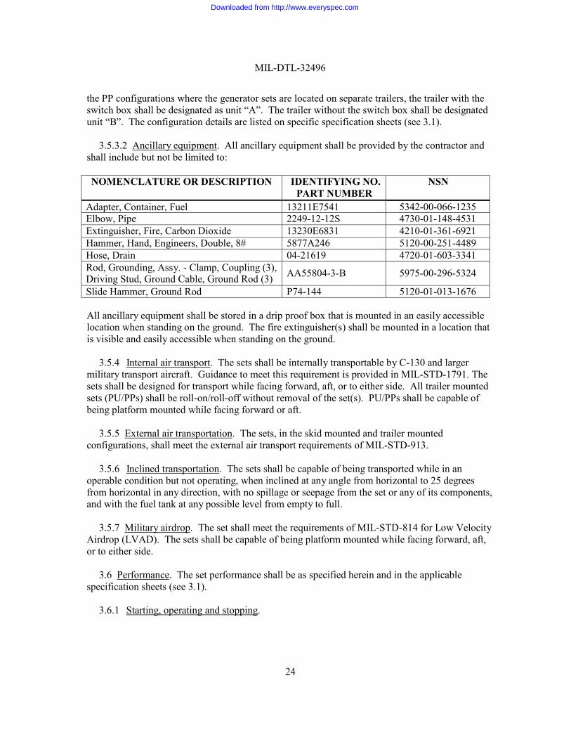
3.5.3.2 Ancillary equipment. All ancillary equipment shall be provided by the contractor and
shall include but not be limited to:
NOMENCLATURE OR DESCRIPTION IDENTIFYING NO. PART NUMBER
NSN
Adapter, Container, Fuel 13211E7541 5342-00-066-1235 Elbow, Pipe 2249-12-12S 4730-01-148-4531 Extinguisher, Fire, Carbon Dioxide 13230E6831 4210-01-361-6921 Hammer, Hand, Engineers, Double, 8# 5877A246 5120-00-251-4489 Hose, Drain 04-21619 4720-01-603-3341 Rod, Grounding, Assy. - Clamp, Coupling (3), Driving Stud, Ground Cable, Ground Rod (3)
AA55804-3-B
5975-00-296-5324
Slide Hammer, Ground Rod P74-144 5120-01-013-1676
All ancillary equipment shall be stored in a drip proof box that is mounted in an easily accessible location when standing on the ground. The fire extinguisher(s) shall be mounted in a location that is visible and easily accessible when standing on the ground.
3.5.4 Internal air transport. The sets shall be internally transportable by C-130 and larger
military transport aircraft. Guidance to meet this requirement is provided in MIL-STD-1791. The sets shall be designed for transport while facing forward, aft, or to either side. All trailer mounted sets (PU/PPs) shall be roll-on/roll-off without removal of the set(s). PU/PPs shall be capable of being platform mounted while facing forward or aft.
3.5.5 External air transportation. The sets, in the skid mounted and trailer mounted
configurations, shall meet the external air transport requirements of MIL-STD-913.
3.5.6 Inclined transportation. The sets shall be capable of being transported while in an operable condition but not operating, when inclined at any angle from horizontal to 25 degrees from horizontal in any direction, with no spillage or seepage from the set or any of its components, and with the fuel tank at any possible level from empty to full.
3.5.7 Military airdrop. The set shall meet the requirements of MIL-STD-814 for Low Velocity
Airdrop (LVAD). The sets shall be capable of being platform mounted while facing forward, aft, or to either side.
3.6 Performance. The set performance shall be as specified herein and in the applicable
specification sheets (see 3.1).
3.6.1 Starting, operating and stopping.
Downloaded from http://www.everyspec.com
MIL-DTL-32496
25
3.6.1.1 Starting. The set shall contain all necessary controls to start the set under all conditions specified herein. The start sequence shall automatically control the starting aids, bypassing the appropriate protective devices, activating the start menu, and other systems related to starting the generator set. Upon completion of the start sequence, the soldier shall be prompted to crank the engine and to complete the starting of the generator set. The set shall start (see 6.4.29) within 5 minutes under basic climatic conditions from -32ºC (-25ºF) to 57ºC (135ºF). The set shall start (see 6.4.29) within 5 minutes after a maximum of 55 minutes of winterization kit operation under cold climatic conditions -46ºC (-50ºF) to –32ºC (-25ºF) under the following conditions:
a. Any individual or combination of the environmental conditions specified in
paragraph 3.8.
b. With the base of the set in planes from level up to 15 degrees from level.
c. With fuels, lubricants, and coolants as specified herein.
3.6.1.2 Operating. Immediately after starting and with a maximum warm-up period of 5 minutes, the set shall accept load and operate without damage (see 6.4.3) or failure (see 6.4.8) under the following conditions:
a. Conditions specified in paragraph 3.6.1.1.
b. All loads, continuous and intermittent, up to and including rated load as
specified herein and in the applicable specification sheets (see 3.1).
3.6.1.3 Stopping. The set shall stop (see 6.4.30) within 2 minutes after activation/deactivation of the master switch (or functionally equivalent device/process), the emergency stop switch, any protective device or other requirements specified herein, intended to stop the set.
3.6.2 Parallel operation. More than two sets of the same size and mode shall automatically
enter parallel operation by activation of two buttons (see 3.4.12.3.2). With their governor and voltage regulator paralleling circuits interconnected, the sets operated in parallel shall divide load IAW the following, as system load (at rated power factor) is varied between zero and 100 percent (and vice versa) of the combined rating of the connected sets:
a. Real power division. At no time shall difference between the average individual
kilowatt outputs of the set, when supplying the system load, be greater than 10 percent of the kilowatt rating of one set.
b. Power exchange. At all constant system loads up to the combined rating of the
sets in parallel, power exchange between the sets shall not exceed 10 percent of the kilowatt rating on one set. Power exchange is the difference between the maximum and minimum power output delivered by one set for constant system load conditions, as determined from oscillographic measurements.
Downloaded from http://www.everyspec.com
MIL-DTL-32496
26
c. Reactive power division. At no time shall the difference in average reactive kilovolt-ampere (kVA) supplied by any two sets differ by more than 10 percent of the reactive kVA rating on one set.
For the above requirements, the initial system load shall be proportionally divided between the sets, both as to activate and reactivate components; thereafter, there shall be no adjustments to governors, voltage regulators, or any other components as system load is changed.
3.6.2.1 Permissive paralleling device. A device shall be used to prevent paralleling of two or
more generator sets until the voltage difference of the same phase of the two generator sets is less than 8 volts. The device shall not be damaged (see 6.4.3) or falsely operate when either of its AC input terminals is raised to 300 volts above ground. The device shall not be damaged (see 6.4.3) when the voltage across the AC input terminals is at any value from 0 to 300 volts.
3.6.2.2 Load transfer. A device shall be provided to automatically transfer load from one set to
the other(s) without producing a voltage or frequency transient.
3.6.3 Fuels. The sets, while operating on Grade No. 1-D (emergency fuel) and 2-D diesel fuel conforming to A-A-52557; JP-5 turbine fuel conforming to MIL-DTL-5624 (emergency fuel); or JP-8 turbine fuel conforming to MIL-DTL-83133 shall meet the specified requirements herein. The sets, while operating on JP-5 emergency turbine fuel conforming to MIL-DTL-5624 (with a cetane rating of 30 to 35) shall meet all requirements herein, except rated load may be reduced 20 percent. Operation on JP-5 shall only be required at temperatures from -18qC (0qF) to 38qC (100qF) and at altitudes up to 914 meter (m) (3,000 feet).
3.6.4 Lubricants. The engine shall start, operate and be storable under all conditions specified
herein, using the following lubricants. Oil conforming to MIL-PRF-2104 shall be used when temperatures are above -26qC (-15qF). Oil conforming to MIL-PRF-46167 shall be used when temperatures are at or below 4qC (40qF). Grease shall conform to MIL-PRF-10924. If used, gear oil shall conform to SAE-J2360.
3.6.5 Coolant. The set shall start, operate, and be storable under all conditions specified
herein, with the following coolants:
a. A-A-52624 antifreeze from -54qC (-65qF) to 57qC (135qF) ambient.
b. Water with MIL-A-53009 additive from 4qC (40qF) to 57qC (135qF) ambient.
3.7 Audio noise. Audio noise sound-pressure levels (SPL) emanating from the set shall be as specified in specification sheets (see 3.1). In addition, audio noise emanating from the set shall not exceed 85 dBA at the operator's station, defined to be 0.7 m (2.3 feet) from the control panel, while the control panel door(s) are open. These requirements apply under all operating conditions specified herein with the set operating at all loads from no-load to rated load.
3.8 Environmental requirements.
Downloaded from http://www.everyspec.com
MIL-DTL-32496
27
3.8.1 Starting and operating. The set shall start and operate under each and any combination of the following operating conditions:
a. All possible relative humidities, with ambient temperatures ranging from -46qC
(-50qF) to 52qC (125qF) at sea level; and from -46qC to 35qC at 1,219 m (-50qF to 95qF at 4,000 feet). The high temperature requirement remains at 35qC (95qF) at altitudes above 1,219 m (4,000 feet).
b. Altitudes up to and including 3,048 m (10,000 feet). Rated load may be
reduced by 3.5 percent for each 305 m increment (1,000 feet) above 1,219 m (4,000 feet) (e.g., at 10,000 feet rated load may be reduced by 21 percent).
c. Temperatures up to and including 57qC (135qF). Rated load may be reduced by
3 percent for each 10 degrees C increment (18 degrees F) above 52qC (125qF).
d. With 127 millimeters (mm) (5 inches) of rain per hour impinging on the set at angles from the vertical up to 45 degrees.
e. With 355 British thermal units (BTUs) per square foot per hour of solar
radiation.
f. With sand and dust particle concentration of up to 1,400 milligrams per cubic meter (mg/m ). Particle sizes shall range from less than 74 micrometers in diameter to 1,000 micrometers with the bulk of the particles ranging in size from 74 to 350 micrometers.
g. With a steady wind speed of 22 meters per second (m/s) (73 feet per second
[ft/s]) and gusts up to 29 m/s (95 ft/s) at a height of 3 m (10 feet) above ground level.
h. With accumulations of ice glaze, freezing rain and hoarfrost of up to 13 mm (0.5
inch) and up to a specific gravity of 0.9.
i. In a salt fog or sea spray environment.
3.8.2 Storage. The set without packaging shall not be damaged (see 6.4.3) by exposure to:
a. Storage at -51qC (-60qF) to 71qC (160qF).
b. Salt fog environment.
c. All possible relative humidities.
3.9 High altitude electromagnetic pulse (HAEMP). All sets operating as a single unit and while operating in parallel (see 3.6.2) shall withstand the HAEMP and radio frequency weapons environment as specified in MIL-STD-2169. The set shall meet the operational requirements
Downloaded from http://www.everyspec.com
MIL-DTL-32496
28
specified herein within 5 minutes after being subjected to the specified HAEMP nuclear environment. The recovery may include manual or automatic correction of HAEMP induced changes in the set, to include a restart, but not the replacement of piece parts or components. The cables to the load shall be 100 feet in length and sets and other equipment shall be configured for worst-case system response during the exposure.
3.10 Electromagnetic interference (EMI). EMI and susceptibility characteristics shall comply
with the requirements of MIL-STD-461 for conducted emissions (CE102), conducted susceptibility (CS101, CS114, CS115 and CS116), radiated emissions (RE102), and radiated susceptibility at 4 meters (RS103).
3.11 Treatment and painting. Treatment and painting shall be IAW MIL-DTL-53072. When
referenced drawings are used, treatment and painting shall be as specified on the referenced drawing.
a. All surfaces of the set, regardless of the material selected, shall have a finish
coat of CARC paint IAW MIL-DTL-64159 or MIL-DTL-53039. Topcoat color shall be green 383, color number 34094 in accordance with FED-STD-595.
b. Where the exterior surface material selected is not applicable to MIL-DTL-
53072 (use of plastic or composites, as an example) the surface shall be treated as necessary for application of the finish coat of CARC as specified paint in paragraph 3.11.a.
c. The following items shall not be painted: engine, alternator, terminal wiring
connections, governor linkage, instruction diagrams and plates, rectifiers, relays, switches, circuit interrupters, instrumentation, rubber, lubrication fittings, hoses and all other parts whose operation or function would be adversely affected by paint.
d. After final assembly and all testing is completed, all exterior surfaces (except
identification plates, markings, instruments and rubber) shall be painted with a finish coat of “CARC” paint in accordance with MIL-DTL-53072. Color shall be Green 383, Tan 686 or specified (see 6.2) camouflage pattern, to be supplied by the Contracting Officer. Application of the pattern shall be in accordance with MIL-DTL-53072.
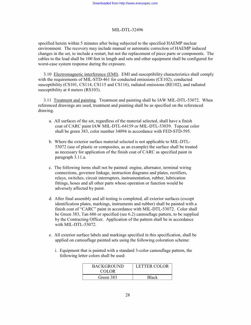
e. All exterior surface labels and markings specified in this specification, shall be
applied on camouflage painted sets using the following coloration scheme:
i. Equipment that is painted with a standard 3-color camouflage pattern, the following letter colors shall be used:
BACKGROUND
COLOR LETTER COLOR
Green 383 Black
Downloaded from http://www.everyspec.com
MIL-DTL-32496
29
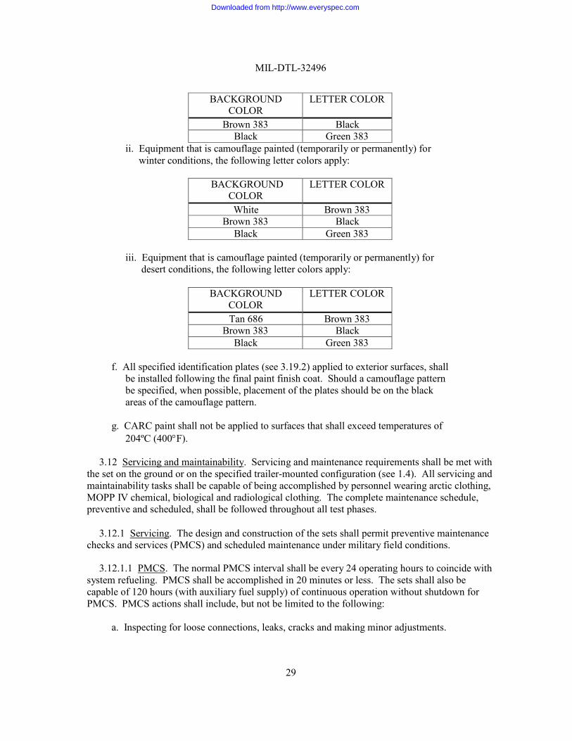
BACKGROUND COLOR
LETTER COLOR
Brown 383 Black Black Green 383
ii. Equipment that is camouflage painted (temporarily or permanently) for winter conditions, the following letter colors apply:
BACKGROUND
COLOR LETTER COLOR
White Brown 383 Brown 383 Black
Black Green 383
iii. Equipment that is camouflage painted (temporarily or permanently) for desert conditions, the following letter colors apply:
BACKGROUND
COLOR LETTER COLOR
Tan 686 Brown 383 Brown 383 Black
Black Green 383
f. All specified identification plates (see 3.19.2) applied to exterior surfaces, shall be installed following the final paint finish coat. Should a camouflage pattern be specified, when possible, placement of the plates should be on the black areas of the camouflage pattern.
g. CARC paint shall not be applied to surfaces that shall exceed temperatures of
204ºC (400qF).
3.12 Servicing and maintainability. Servicing and maintenance requirements shall be met with the set on the ground or on the specified trailer-mounted configuration (see 1.4). All servicing and maintainability tasks shall be capable of being accomplished by personnel wearing arctic clothing, MOPP IV chemical, biological and radiological clothing. The complete maintenance schedule, preventive and scheduled, shall be followed throughout all test phases.
3.12.1 Servicing. The design and construction of the sets shall permit preventive maintenance
checks and services (PMCS) and scheduled maintenance under military field conditions.
3.12.1.1 PMCS. The normal PMCS interval shall be every 24 operating hours to coincide with system refueling. PMCS shall be accomplished in 20 minutes or less. The sets shall also be capable of 120 hours (with auxiliary fuel supply) of continuous operation without shutdown for PMCS. PMCS actions shall include, but not be limited to the following:
a. Inspecting for loose connections, leaks, cracks and making minor adjustments.
Downloaded from http://www.everyspec.com
MIL-DTL-32496
30
b. Checking and adding lubricating oil.
c. Draining of contaminants from fuel filters and water separator using drain valves.
d. Checking and servicing of batteries.
e. Checking and adding coolant if applicable.
3.12.1.2 Minimum scheduled maintenance interval. The minimum scheduled maintenance
interval (hours of set operation) between scheduled maintenance service (repair, adjust, replace, etc.) shall not be less than 500 hours (5, 10, and 15 kW sets) and 750 hours (30 and 60 kW sets). Set design shall minimize the need and time to perform scheduled maintenance. Scheduled maintenance actions shall include but not be limited to the following:
a. Checking air cleaner. Service and replace filter as necessary.
b. Changing lubricating oil and filters.
c. Servicing and replacement of water separator element.
d. Draining and replacing coolant if applicable.
e. Changing or cleaning fuel filter elements on strainer. All other scheduled maintenance service for the set life shall be as listed in the applicable technical manuals, except that injectors shall not require scheduled maintenance or replacement at intervals less than 1,500 hours. One person (MOS-91D) shall be able to change the oil and oil filter within 20 minutes.
3.12.2 Maintainability. The generator sets shall be designed to meet scheduled and
unscheduled service and maintenance requirements with minimum removal of components. Scheduled maintenance shall not require removal of any other set component to perform the scheduled maintenance action. Maintainability requirements shall be applicable to the generator set while operating on the ground or in the specified trailer mounted configuration (see 1.4). The following specific maintainability items shall be provided on all set sizes, 5 through 60 kW:
a. A means to quickly and easily check and add oil while the set is operating.
b. A means to bleed the fuel system of air and/or water with the set off.
c. A relay socket with a positive locking mechanism shall be provided for each relay.
d. All modules/Line Replaceable Units (LRUs) shall interface with the wiring
harness or other modules through quick disconnect plugs with a locking
Downloaded from http://www.everyspec.com
MIL-DTL-32496
31
mechanism. The plugs used on wiring harnesses shall not be crimped and shall be easily repairable. Solder or crimp contacts may be used.
e. Hardware that requires torqueing shall be installed so that the nut, bolt or screw
head is accessible for torque wrench application. In assemblies where both a bolt and nut are used, the nut shall be accessible for torque wrench application.
f. Test, measurement and diagnostic equipment (TMDE) required for
maintenance shall currently exist in the DOD supply system. When TMDE is required, it shall be selected using criteria from AR 750-43, Army TMDE Program.
g. All maintenance actions shall be accomplished using standard tools in the
military inventory.
h. The generator sets shall be repairable and maintainable using the standard tools in the General Mechanic's Tool Kit, (SC 5180-90-CL-N26-HR; NSN 5180-00- 177-7033; LIN W33004) and any special tools listed in the Repair Parts and Special Tools List (RPSTL).
3.12.3 Maintenance ratio (MR). Field level MR (see 6.4.15) of the set shall not exceed 0.025.
3.12.4 Median time to repair (MTTR). The MTTR (see 6.4.18) for all unscheduled
maintenance actions at the field level shall not exceed 1.5 hours.
3.12.5 Maximum time to repair (MAXTTR). The MAXTTR (see 6.4.16) for 90 percent of all essential unscheduled maintenance actions shall not exceed 2 hours.
3.13 Workmanship. Workmanship shall be of a quality to assure delivery of sets that are free
from defects (see 6.4.6) resulting from defective material and incorrect manufacturing or assembly practices.
3.14 Nuclear, Biological, and Chemical (NBC) Contamination Survivability. The set shall
have a Chemical Agent Resistant Coating (CARC) painted as specified herein. The set shall be capable of being serviced and maintained (see 3.12) by personnel wearing Mission Oriented Protective Posture (MOPP) IV chemical, biological, and radiological clothing (see 6.4.19) without special tools or support equipment. The set shall not be damaged and shall meet operational requirements specified herein, within 60 minutes after being decontaminated according to the procedure specified in Appendix A. Lenses or covers, gaskets, seals, marking, control knobs, and other devices on the control panel or display functions shall not be damaged by the NBC decontamination procedure. Any changes to the set shall be made in such a way as to minimize the collection and retention of agents and decontaminants. Design guidance is available from MIL-HDBK-784.
3.15 Safety. The sets shall meet the provisions of MIL-STD-882; paragraph 5.13 of MIL-
STD-1472; as specified in paragraph 3.16; and the safety design criteria as specified herein.
Downloaded from http://www.everyspec.com
MIL-DTL-32496
32
Exposed parts of such nature as to be a hazard to personnel shall be insulated, enclosed or guarded without impairing the functioning of these parts.
3.15.1 Fail-safe. The sets designs shall provide fail-safe (see 6.4.9) features for safety of
personnel during the installation, operation, maintenance, and repair or interchanging of a complete equipment assembly or component parts thereof.
3.15.2 Temperature. Operator accessible components shall comply with the temperature limits
shown in UL-60950-1, table 4B. At an ambient temperature of 25°C (77ºF), the operating temperature of control panels and operating controls shall not exceed 57°C (135ºF). Other exposed parts subject to contact by operating personnel shall not exceed 60°C (140ºF). Hot surfaces shall be clearly marked/labeled.
3.15.3 Electrical. The set designs shall incorporate methods to protect personnel from
inadvertent/accidental contact with voltages capable of producing shock hazards (voltages in excess of 30 volts rms or DC) during normal operation of equipment. The sets shall have all external surfaces at the same potential. All contacts, terminals and like devices having voltages between 70 and 500 volts rms or DC with respect to ground shall be guarded from accidental contact by personnel if such points are exposed to contact during direct support or operator maintenance. Guards or barriers shall be provided with test probe holes where maintenance testing is required IAW UL-60950-1, paragraph 2.1 to 4.4.
3.15.4 Connectors. Connectors used in multiple electric circuits shall preclude mismating.
Where design considerations require plug and receptacles of similar configuration in close proximity, the mating plugs and receptacles shall be suitably coded or marked to clearly indicate the mating connectors. The design of the connector shall be such that the operator is not exposed to electrical shock or burns when normal disconnect methods are used. Exposed pin contacts shall not be energized (hot) after being disconnected from the socket contacts.
3.15.5 Mechanical. The design of the equipment shall provide personnel maximum access and
safety while installing, operating, and maintaining the equipment. Equipment design shall include provisions to prevent accidental pulling out of drawers or rack mounted equipment components. Suitable protection shall be provided to prevent contact with moving mechanical parts such as gears, fans, and belts when the equipment is complete and operating. Sharp edges/projections shall be eliminated. Doors or hinged covers shall be rounded at the corners and provided with stops to hold them open.
3.15.6 Insulation of controls. All control shafts and bushings thereof shall be grounded
whenever practicable. Alternatively, the control knobs or levers and all attachment screws that can be contacted during use shall be electrically insulated from the shaft.
3.15.7 Equipment grounding. Equipment grounding shall comply with the requirements of
NFPA 70, Article 250. Hinges and slides shall not be relied upon as the sole means of grounding.
3.16 Human factors engineering (HFE). The sets shall be designed IAW accepted criteria of design for HFE as described in MIL-STD-1472. The sets shall be operable and maintainable
Downloaded from http://www.everyspec.com
MIL-DTL-32496
33
during day and night by 5th percentile female through 95th percentile male soldiers when wearing the clothing, which is appropriate to the environments detailed herein.
3.17 Secure lighting. All light sources except display panel backlights, shall meet the
following secure lighting (blue/green) requirements:
a. Light sources shall consist of light emitting diodes (LEDs).
b. 95 percent of the light energy emitted by each light source shall be at wavelengths below 700 nanometers.
c. All light sources shall be visible in bright sunlight.
3.18 Identification, marking, and information. The sets shall be permanently identified and marked
and have information and instruction plates as specified herein and applicable specification sheets (see 3.1).
3.18.1 Parts identification. Parts shall be identified IAW MIL-STD-130.
4. VERIFICATION
4.1 Classification of inspection. Inspections as specified herein, shall be classified as follows:
a. First article pre-production inspection (see 4.4). b.
First article production inspection (see 4.5).
c. Conformance inspection (see 4.6). d.
Inspection comparison (see 4.7).
4.2 Inspection conditions. Unless otherwise specified, all inspections shall be performed IAW the test conditions specified in applicable test method document or applicable paragraphs in the specification.
4.2.1 Fuel, lubrications, and coolant for inspection. No. 2-D diesel fuel conforming to A-A-
52557 or JP-8 conforming to MIL-DTL-83133 shall be used for all tests unless otherwise specified herein. No. 1-D diesel fuel conforming to A-A-52557 or JP-8 conforming to MIL-DTL-83133 shall be used for all testing with ambient temperatures between -51qC (-60qF) to -18qC (0qF). Lubricating oil shall be as follows:
Downloaded from http://www.everyspec.com
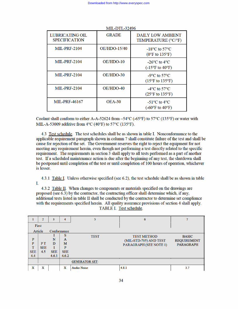
Downloaded from http://www.everyspec.com
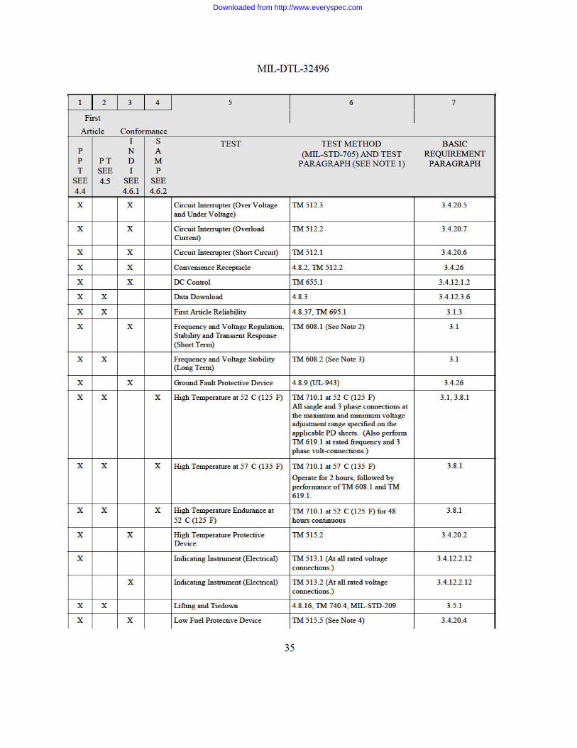
Downloaded from http://www.everyspec.com
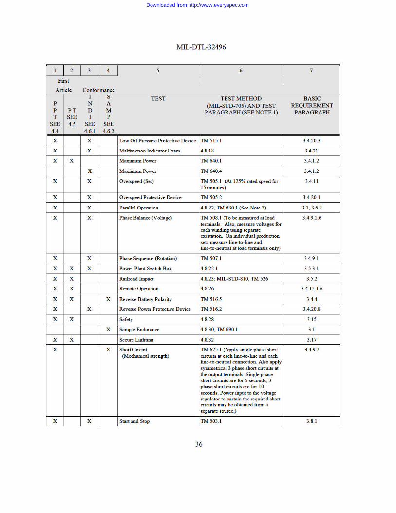
Downloaded from http://www.everyspec.com
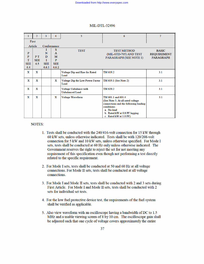
Downloaded from http://www.everyspec.com
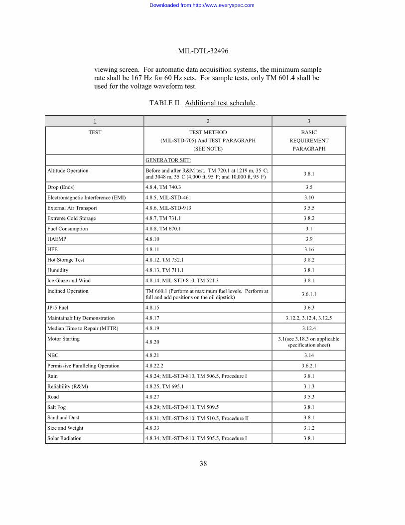
MIL-DTL-32496
38
viewing screen. For automatic data acquisition systems, the minimum sample rate shall be 167 Hz for 60 Hz sets. For sample tests, only TM 601.4 shall be used for the voltage waveform test.
TABLE II. Additional test schedule.
1 2 3
TEST TEST METHOD (MIL-STD-705) And TEST PARAGRAPH
(SEE NOTE)
BASIC REQUIREMENT
PARAGRAPH
GENERATOR SET:
Altitude Operation Before and after R&M test. TM 720.1 at 1219 m, 35 C; and 3048 m, 35 C (4,000 ft, 95 F; and 10,000 ft, 95 F)
3.8.1
Drop (Ends) 4.8.4, TM 740.3 3.5
Electromagnetic Interference (EMI) 4.8.5, MIL-STD-461 3.10
External Air Transport 4.8.6, MIL-STD-913 3.5.5
Extreme Cold Storage 4.8.7, TM 731.1 3.8.2
Fuel Consumption 4.8.8, TM 670.1 3.1
HAEMP 4.8.10 3.9
HFE 4.8.11 3.16
Hot Storage Test 4.8.12, TM 732.1 3.8.2
Humidity 4.8.13, TM 711.1 3.8.1
Ice Glaze and Wind 4.8.14; MIL-STD-810, TM 521.3 3.8.1
Inclined Operation TM 660.1 (Perform at maximum fuel levels. Perform at full and add positions on the oil dipstick)
3.6.1.1
JP-5 Fuel 4.8.15 3.6.3
Maintainability Demonstration 4.8.17 3.12.2, 3.12.4, 3.12.5
Median Time to Repair (MTTR) 4.8.19 3.12.4
Motor Starting 4.8.20 3.1(see 3.18.3 on applicable
specification sheet)
NBC 4.8.21 3.14
Permissive Paralleling Operation 4.8.22.2 3.6.2.1
Rain 4.8.24; MIL-STD-810, TM 506.5, Procedure I 3.8.1
Reliability (R&M) 4.8.25, TM 695.1 3.1.3
Road 4.8.27 3.5.3
Salt Fog 4.8.29; MIL-STD-810, TM 509.5 3.8.1
Sand and Dust 4.8.31; MIL-STD-810, TM 510.5, Procedure II 3.8.1
Size and Weight 4.8.33 3.1.2
Solar Radiation 4.8.34; MIL-STD-810, TM 505.5, Procedure I 3.8.1
Downloaded from http://www.everyspec.com
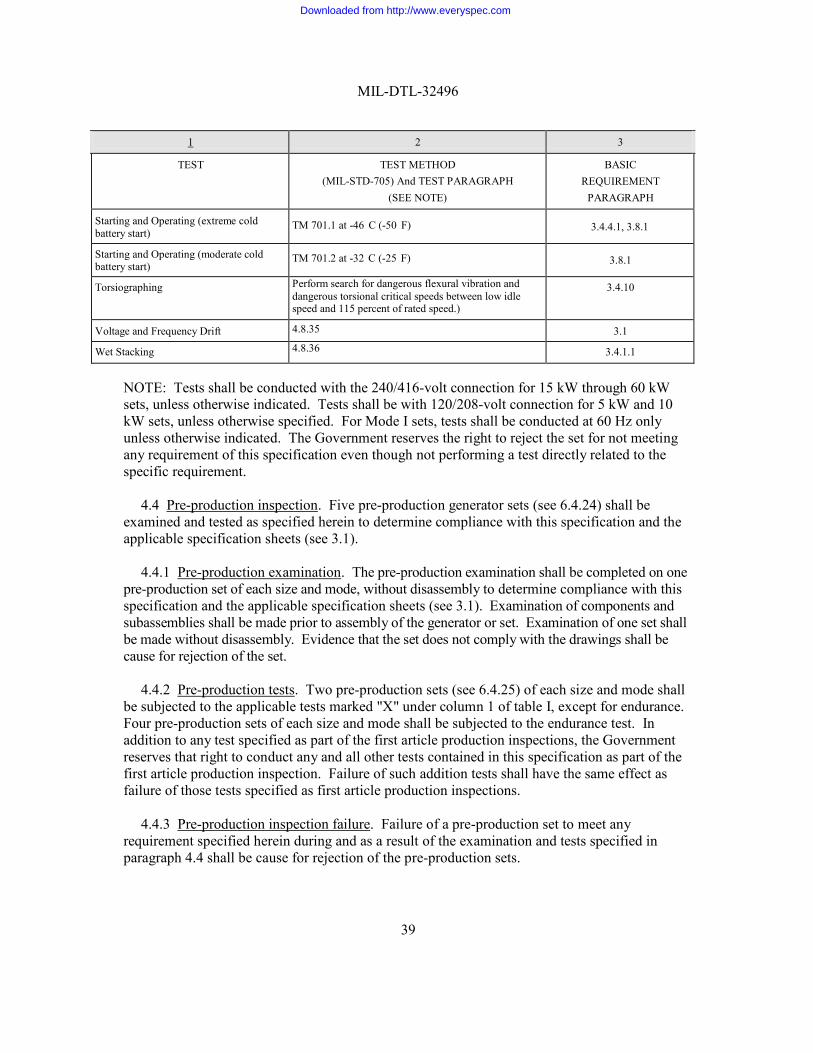
39
MIL-DTL-32496
1 2 3
TEST TEST METHOD (MIL-STD-705) And TEST PARAGRAPH
(SEE NOTE)
BASIC REQUIREMENT
PARAGRAPH
Starting and Operating (extreme cold battery start)
TM 701.1 at -46 C (-50 F)
3.4.4.1, 3.8.1
Starting and Operating (moderate cold battery start)
TM 701.2 at -32 C (-25 F)
3.8.1
Torsiographing Perform search for dangerous flexural vibration and dangerous torsional critical speeds between low idle speed and 115 percent of rated speed.)
3.4.10
Voltage and Frequency Drift 4.8.35 3.1
Wet Stacking 4.8.36 3.4.1.1
NOTE: Tests shall be conducted with the 240/416-volt connection for 15 kW through 60 kW sets, unless otherwise indicated. Tests shall be with 120/208-volt connection for 5 kW and 10 kW sets, unless otherwise specified. For Mode I sets, tests shall be conducted at 60 Hz only unless otherwise indicated. The Government reserves the right to reject the set for not meeting any requirement of this specification even though not performing a test directly related to the specific requirement.
4.4 Pre-production inspection. Five pre-production generator sets (see 6.4.24) shall be
examined and tested as specified herein to determine compliance with this specification and the applicable specification sheets (see 3.1).
4.4.1 Pre-production examination. The pre-production examination shall be completed on one
pre-production set of each size and mode, without disassembly to determine compliance with this specification and the applicable specification sheets (see 3.1). Examination of components and subassemblies shall be made prior to assembly of the generator or set. Examination of one set shall be made without disassembly. Evidence that the set does not comply with the drawings shall be cause for rejection of the set.
4.4.2 Pre-production tests. Two pre-production sets (see 6.4.25) of each size and mode shall
be subjected to the applicable tests marked "X" under column 1 of table I, except for endurance. Four pre-production sets of each size and mode shall be subjected to the endurance test. In addition to any test specified as part of the first article production inspections, the Government reserves that right to conduct any and all other tests contained in this specification as part of the first article production inspection. Failure of such addition tests shall have the same effect as failure of those tests specified as first article production inspections.
4.4.3 Pre-production inspection failure. Failure of a pre-production set to meet any
requirement specified herein during and as a result of the examination and tests specified in paragraph 4.4 shall be cause for rejection of the pre-production sets.
Downloaded from http://www.everyspec.com
40
MIL-DTL-32496
4.5 First article production inspection. Five production generator sets shall be examined and tested as specified herein to determine compliance with this specification and the applicable specification sheets (see 3.1).
4.5.1 Production examination. The production examination shall be completed on one
production set of each size and mode, without disassembly to determine compliance with this specification and the applicable specification sheets (see 3.1). Examination of components and subassemblies shall be made prior to assembly of the generator or set. Examination of one set shall be made without disassembly. Evidence that the set does not comply with the drawings shall be cause for rejection of the set.
4.5.2 Production tests. Two production sets of each size and mode shall be subjected to the
applicable tests marked "X" under column 2 of table I, except for endurance. Four production sets of each size and mode shall be subjected to the endurance test. In addition to any test specified as part of the first article production inspections, the Government reserves that right to conduct any and all other tests contained in this specification as part of the first article production inspection. Failure of such addition tests shall have the same effect as failure of those tests specified as first article production inspections.
4.5.3 Production Inspection failure. Failure of a production set to meet any requirement
specified herein during and as a result of the examination and tests specified in paragraph 4.5 shall be cause for rejection of the production sets and shall be cause for refusal by the Government to continue acceptance of production sets until evidence has been provided by the contractor that corrective action has been taken to eliminate the deficiencies. Correction of such deficiencies shall be accomplished by the contractor at no cost to the Government on sets previously accepted and produced under the contract. Any deficiencies found as a result of the production inspection shall be considered prima facie evidence that all sets accepted prior to the completion of production inspection are similarly deficient unless evidence to the contrary is furnished by the contractor and such evidence is acceptable to the contracting officer.
4.6 Conformance inspection.
4.6.1 Individual set inspection. Each production set shall be examined and tested (see
4.6.1.1), without disassembly, for conformance to this specification and the applicable specification sheets (see 3.1). Noncompliance with this specification shall be cause for rejection.
4.6.1.1 Tests. Each set shall be subjected to the tests marked "X" under column 3 of table I.
Failure of any test shall be cause for rejection.
4.6.2 Sample inspection. Sampling shall be IAW ANSI/ASQC Z1.4 after all sets comprising a lot have passed the inspection specified in paragraph 4.6.1. Unless otherwise specified (see 6.2), lot sizes shall consist of not more than 50 sets except that the first lot shall contain not less than 25 sets. For a lot size of 50 or less, a minimum sample size of 2 shall be used. A lot shall be accepted when zero defects (see 6.4.6) are found and rejected when one or more defects are found. No adjustment or substitution of components shall be made on the sets selected for sample inspection.
Downloaded from http://www.everyspec.com
41
MIL-DTL-32496
4.6.2.1 Tests. Sets selected IAW paragraph 4.6.2 shall be subjected to the tests marked "X" under column 4 of table I in the order listed with the exception that the sample endurance test shall be conducted on 50 percent of the samples from each lot or on 2 samples per lot, whichever is greater. When this 50 percent results in fraction of sets, the next highest number representing complete sets shall be used. A sample set which fails to meet a requirement during any test shall be considered a defective set. Failure of any sample set to meet any requirement herein shall be cause for rejection of the lot. Rejection shall be the cause for Government to refuse further acceptance of production sets until Government-approved correction of deficiencies has been implemented. The Government may choose that the rejected lot, after correction of deficiencies, undergo any or all of the table I, column 4 tests, prior to acceptance of the lot or acceptance of further production sets. Correction of deficiencies and retesting of rejected sets or lots shall be accomplished by the contractor under Government supervision at no cost to the Government.
4.7 Inspection comparison. The Government may select sets at any time during the contract
production period and subject these sets to any examination and test specified herein, necessary to determine that the selected sets meet all requirements of this specification. The inspection shall be performed by the Government at a site selected by the Government. Sets shall be selected at random from those that have been accepted by the Government, and shall not include the previously inspected pre-production model and production sets. Acceptance of an inspection comparison set shall not exclude the remaining sets from the quality conformance inspection and acceptance provisions specified in section 4. In addition to any test specified as part of the inspection comparison, the Government reserves the right to conduct any and all other tests contained in this specification as part of the inspection comparison, and failure of such additional tests shall have the same effect as failure of those tests specified as inspection comparison.
4.7.1 Inspection failure. Failure of an inspection comparison set to meet any requirement
specified herein, during and as a result of the examination and tests specified in paragraph 4.7, shall be cause for refusal by the Government to continue acceptance of production sets until the contractor has provided evidence that corrective action has been taken to eliminate the deficiencies. Correction of such deficiencies shall be accomplished by the contractor at no cost to the Government on sets previously accepted and produced under the contract. Any deficiencies found as a result of the inspection comparison shall be considered prima facie evidence that all sets accepted prior to completion of the inspection comparison are similarly deficient unless evidence to the contrary is furnished by the contractor and such evidence is acceptable to the contracting officer.
4.8 Test procedures. Tests shall be conducted IAW MIL-STD-705, MIL-STD-810, and as
specified herein. For reference purposes, test preparations and set-up procedures are described in MIL-HDBK-705. Test instruments shall be of the laboratory type and shall have been calibrated within 30 days of the start of testing and at six-month periods thereafter. Instruments used in calibration should be at least five times the accuracy of the instrument being calibrated. Direct-reading instruments shall have at least 0.5 percent accuracy and shall be connected to indicate the most accurate portion of their range. On DC instruments, the readings shall not be made on the lower 15 percent of the scale. On AC instruments, the readings shall not be made on the lower one-third of the scale. Oscillograph galvanometer frequency response shall be flat
Downloaded from http://www.everyspec.com
42
MIL-DTL-32496
(±5 percent) from DC to not less than 3,000 Hz. The voltage and frequency recording-type meters, other than oscillographs, shall have the following specifications:
a. Rise time for the frequency to be 250 ms.
b. Rise time for the voltage to be 60 ms.
c. Input to be up to 500 volts RMS.
d. Output to be ±5 volts DC maximum.
e. The signal input(s) and output(s) shall be ungrounded. In addition, if an analog signal is digitized for the purpose of automation, the sampling frequency shall be at least 25 percent higher than twice the highest frequency component of the analog signal; (i.e. The sampling frequency for voltage waveforms acquired using the above oscillograph is 7.5 kHz; 3.75 MHz for the oscilloscope cited in table I, Note 6, and in the voltage waveform paragraph of the applicable specification sheet (see 3.1).) The sampling frequency for any waveforms acquired using the above voltage and frequency recording-type meter shall be at least 100 Hz. The data shall be saved in ASCII text file on CD-ROM or DVD.
If an automated testing system is used, the contractor shall verify the results of the automated testing system using Gould voltage and frequency recording type meter, part number 2108-2202- 005542 or 30-V8-202-106-383.
4.8.1 Audio noise test. Instrumentation and procedures for the audio noise test shall conform
to Appendix B, TM 100.1. Measure audio noise sound pressure level at no load and rated load. The microphone(s) shall be located at 7 m (22.9 feet) from the perimeter of the set and 1.2 m (4 ft) above the ground. Measure audio noise sound pressure levels at 0.7 m from the control panel, at a height equal to the control panel, with the set on the ground, and with the control panel door(s) open.
4.8.2 Convenience receptacle test. Perform a circuit interrupter test on the convenience
receptacle in accordance with TM 512.2 of MIL-STD-705. 4.8.3 Data download Test. The data download test shall be conducted by connecting a
commercial IBM compatible PC, to include the MSD, to the set RS-485 serial port (see 3.4.12.3.6) using a “Local” cable (04-21227) connected between the RS-485 serial port (labeled “REMOTE”) located on the DCS and the MSD’s RS-232 port. The test shall consist of downloading the operational log and operational data; fault log and fault data; and maintenance log with applicable prompts/actions. All files shall be downloaded and printed, and reviewed for format and data storage capacity. Maximum download time is 15 minutes total for download of operational, fault and maintenance logs and data. Generator set batteries shall be removed to verify data retention without battery power.
4.8.4 Drop test (Ends). The drop test shall be performed on skid mounted configurations
IAW TM 740.3 of MIL-STD-705 at a height of 9 inches.
Downloaded from http://www.everyspec.com
43
MIL-DTL-32496
4.8.5 Electromagnetic interference (EMI) test. The EMI test shall be performed IAW the following procedures of MIL-STD-461:
4.8.5.1 Procedure 1. - CE102, conducted emissions, power leads, 10 kHz to 10 MHz. With
the 50-foot cable connected to the test unit output and energized during the no-load test, determine the broadband conducted emissions (10 kHz to 10 MHz) on each conductor at the end of the cable at no-load, rated load @ 1.0 PF and rated load @ 0.8 PF at all voltage and frequency connections. Conducted emissions exceeding the limit of figure CE102-1 of MIL-STD-461 shall be cause for rejection.
4.8.5.2 Procedure 2. - CS101, conducted susceptibility, power leads, 30 Hz to 150 kHz. The
test procedure is applied to AMMPS sets to evaluate their ability to withstand 30 Hz to 150 kHz input signals coupled to 50-foot output power leads for source voltages above 28 volts. Testing is conducted while operating at no-load, rated load @ 1.0 PF and rated load @ 0.8 PF at all voltage and frequency connections.
4.8.5.3 Procedure 3. - CS114, conducted susceptibility, bulk cable injection, 10 kHz to 200
MHz. The test procedure is applied to AMMPS sets to evaluate their ability to withstand 10 kHz to 200 MHz RF input signals coupled to 50-foot output power leads induced by current probe. Testing is conducted while operating at no-load, rated load @ 1.0 PF and rated load @ 0.8 PF at all voltage and frequency connections.
4.8.5.4 Procedure 4. - CS115, conducted susceptibility, bulk cable injection, impulse
excitation. The test procedure is applied to AMMPS sets to evaluate their ability to withstand a 30 Hz impulse excitation (5 Amps) coupled to 50-foot output power leads. Testing is conducted while operating at no-load, rated load @ 1.0 PF and rated load @ 0.8 PF at all voltage and frequency connections.
4.8.5.5 Procedure 5. - CS116, conducted susceptibility, damped sinusoidal transients, cables
and power leads, 10 kHz to 100 MHz. The test procedure is applied to AMMPS sets to evaluate their ability to withstand a 1 to 2 Hz damped sinusoidal impulse (figure CS116-1 of MIL-STD- 461F) coupled to 50-foot output power leads. Testing is conducted while operating at no-load, rated load @ 1.0 PF and rated load @ 0.8 PF at all voltage and frequency connections.
4.8.5.6 Procedure 6. - RE102, radiated emissions, electric field, 10 kHz to 18 GHz. With the
50-foot cable connected to the test unit output and energized during the no-load test, determine the radiated emissions (10 kHz to 18 GHz) at no-load, rated load @ 1.0 PF and rated load @ 0.8 PF at all voltage and frequency connections. Radiated emissions exceeding the limit of figures RE102-1 through RE102-4 of MIL-STD-461F shall be cause for rejection.
4.8.5.7 Procedure 7. - RS103, radiated susceptibility, electric field, 2 MHz to 40 GHz.
a. Determine those frequencies at which the test unit is susceptible. At these frequencies, determine the threshold of susceptibility. Record all pertinent data.
Downloaded from http://www.everyspec.com
44
MIL-DTL-32496
b. With the 50-foot cable connected to the test unit and energized during the no-load test, subject the test unit to electric fields to 50 V/m while operating at no-load, rated load @ 1.0 PF and rated load @ 0.8 PF and at all voltage and frequency connections.
c. The test unit output voltage shall be monitored throughout the test with the
recording voltage and frequency meter operating at 6 inches per hour until voltage or frequency variations as a function of field strength or frequency are noted. Upon observing such variation, the chart speed shall be increased to 6 inches per minute and the frequency spectrum in question shall be rescanned for acceptance/rejection analysis.
d. Compare the short-term stability of the test results with the short-term
stability of the requirement for both voltage and frequency. Failure of the output voltage or frequency to remain within the 30-second short-term stability bandwidth (which is established prior to the application of the various electrical fields) when subjected to the specified electrical fields shall be cause for rejection.
4.8.6 External air transport. This requirement shall be tested IAW MIL-STD-913 and
certified by the US Army Natick Research, Development, and Engineering Center (ATTN: SSCNC-UTE, Natick, MA 01760-5017).
4.8.7 Extreme cold storage test. The test shall be conducted IAW TM 731.1 of MIL-STD-
705 except at an extreme cold temperature of -51qC (-60qF) instead of -62qC (-80qF).
4.8.8 Fuel consumption. The fuel consumption test shall be conducted with No. 2-D diesel fuel at 60 Hz and 400 Hz, IAW TM 670.1 of MIL-STD-705 except the mission profile shall be 72 hrs at the following load cycle:
Time (hours) Load (kW)
12 Rated 24 ¾ 24 ½ 12 ¼
4.8.9 Ground fault protective device. This device shall be tested IAW UL-943.
4.8.10 HAEMP tests and analyses. This test shall be conducted IAW the Detailed Test Plan
for First Article Pre-production Test (FAPT) of Tactical Quiet (TQ) Generator Sets and Towed Assemblages, Nuclear Effects Directorate, U.S. Army Test and Evaluation Command, dated December 1989 (Classified). The test shall be conducted in both skid and trailer mounted configurations (see 3.1). The set, PU, and PP shall be operated as a single unit and in parallel mode.
Downloaded from http://www.everyspec.com
45
MIL-DTL-32496
4.8.11 HFE exam. An HFE examination shall be conducted IAW Appendix B, TM 103.1.
4.8.12 Hot storage test. Perform IAW TM 732.1 of MIL-STD-705 at 71qC (160qF).
4.8.13 Humidity test. The humidity test shall consist of 5 consecutive 48-hour cycles as specified in TM 711.1 of MIL-STD-705.
4.8.14 Ice glaze and wind test. The set shall be tested IAW TM 521.3, of MIL-STD-810,
subjected to the combined action of wind and ice as follows:
a. Perform TM 608.1 of MIL-STD-705.
b. With the ambient temperature between -23qC (-10qF) and 0qC (32qF), and with a steady wind speed of at least 22.25 m/s (73 ft/s), deliver a uniform rain spray on the non operating set until 12.7 mm (0.5 inch) of ice glaze has accumulated on the top of the set.
c. After accumulation of 12.7 mm (0.5 inch) on the top of the set, the set shall be
started and operated at no load for a minimum of 1 hour.
d. After 1 hour of operation at no load, TM 608.1 of MIL-STD-705 shall be performed.
4.8.15 JP-5 fuel test. The fuel test shall be performed using JP-5 fuel as follows:
a. Perform a high temperature test at 52qC (125qF) IAW TM 710.1 of MIL-STD-
705, except that section 710.1.3.2 shall be modified as follows: Perform only paragraphs a and g (TM 608.1 only).
b. Perform a moderate cold test at -18qC (0qF) IAW 701.2 of MIL-STD-705,
except that section 701.2.3.2k shall be modified as follows: Perform TM 608.1 only.
c. Operate each test article (see 3.2) for a total of 300 hours IAW TM 690.1 of
MIL-STD-705. Acceptance criteria for the 300-hour operation run shall be zero relevant or critical failures. JP-5 fuel shall conform to MIL-DTL-5624.
4.8.16 Lifting and tiedown provisions. All sets shall be statically tested to ensure that the
lifting and tiedown provisions and connecting structure meet the requirements of MIL-STD-209.
4.8.17 Maintainability demonstration. The maintainability demonstration shall consist of performance of all scheduled maintenance (PMCS) IAW paragraph 3.12. Arctic mittens and MOPP IV gear shall be used. Any item of service, which cannot be performed with arctic
Downloaded from http://www.everyspec.com
46
MIL-DTL-32496
mittens or MOPP IV gear, shall constitute a failure. Verify MR (see 3.12.3), MTTR (see 3.12.4) and MAXTTR (see 3.12.5).
4.8.18 Malfunction indicator exam. Indicator operation shall be noted throughout all testing.
4.8.19 Median time to repair (MTTR) Test. The MTTR test shall determine, for each size 5-
60 kW AMMPS set (for this test, the 50/60 Hz and 400 Hz models are considered to be equivalent), the MTTR for all field level repair actions. The field level repair actions shall be as detailed by the applicable generator set size technical publication and maintenance allocation chart (MAC). Each MAC field level repair action shall be demonstrated within the following constraints:
a. Use of allowable tools only (see 3.12.2.h).
b. Following the repair procedures detailed in the applicable Operator/Field Repair
technical publication.
c. Each repair action shall start from a completely assembled generator set.
d. Each repair action shall remove and replace the part/component/assembly (LRU).
e. Each repair action shall conclude by returning the generator set to a fully assembled condition.
f. The Time to Repair (TTR) for each action shall be recorded (in total minutes) and
verified by a Government representative.
g. The arithmetic median shall be obtained by tallying the total time(s) for all field level actions and determining the median time, which shall not exceed 90 minutes.
4.8.20 Motor starting test. The motor starting test shall be performed by use of a motor rated
at 1 horsepower per kW of set kW rating. The starting current rating of the motor shall be NEMA Code F, in accordance with MG-1. The motor shall be loaded with a flywheel or equivalent having inertia equal to that of the motor rotor. Satisfactory starting is defined as acceleration of the motor to rated speed without tripping any generator set protective devices.
4.8.21 Nuclear, biological, and chemical (NBC) test. An NBC test shall be conducted IAW
Appendix A.
4.8.22 Parallel operation test. For pre-production model testing (column 1 of table I), two sets of each size and mode shall be tested IAW TM 630.1 of MIL-STD-705. Additionally, conduct parallel test with three sets. For individual set verification testing (column 3 of table I), each production set shall be tested in parallel with the first set of same production lot sets (see 6.2). Each set selected as the test set shall be tested with the next test set selected from the next lot. The set selected as the paralleling master set (test set) per lot, shall not be the quality control
Downloaded from http://www.everyspec.com

47
MIL-DTL-32496
sample set(s) of that same lot. Testing shall be IAW TM 630.1 of MIL-STD-705 with the following changes:
a. Control panel instrumentation on the sets shall be used.
b. Load connections shall be no-load, half-load, and rated load.
c. Where 1 hour of operation is referenced, substitute 15 minutes of operation.
4.8.22.1 PP/switch box testing. Each PP with its associated switch box (see 3.1) shall be
parallel tested IAW TM 630.1 of MIL-STD-705 with the following changes:
a. Control panel instrumentation on the switch boxes shall be used.
b. Load connections shall be no-load, half-load, and rated load.
c. Where 1 hour of operation is referenced, substitute 15 minutes of operation.
4.8.22.2 Permissive paralleling test. Two or more sets (see 3.1) shall be parallel tested IAW 630.1 of MIL-STD-705 with the following changes:
a. Control panel instrumentation on the switch boxes shall be used.
b. Load connections shall be no-load, half-load, and rated load.
c. Verify that two or more generator sets of the same mode shall not parallel until the voltage difference of the same phase is less than 8 volts.
d. Verify that the permissive paralleling device shall not be damaged or falsely
operate when: either of its AC terminals is raised to 300 volts above ground; when the voltage across the AC input terminals is at any value from 0 to 300 volts.
e. Where 1 hour of operation is referenced, substitute 15 minutes of operation.
4.8.23 Railroad impact test. The sets, PUs and PPs shall be rail impact tested IAW TM 526,
of MIL-STD-810, using the appropriate prime mover. The test shall be performed with the following conditions:
a. Two sets, PUs and PPs of each size and configuration (see 3.2) shall be used.
b. The two sets shall be mounted in opposite direction to each other. The two PUs
and PPs of each configuration (see 3.2) shall be mounted with the trailer longitudinal axis parallel to the length of the flat car but in opposite directions.
Downloaded from http://www.everyspec.com
48
MIL-DTL-32496
c. The sets, PUs and PPs shall be secured to the railcar IAW approved set and trailer mounted rail tie-down procedures.
d. The sets, PUs and PPs shall not require any type of packaging for the test.
e. Fuel tanks shall be half full during test.
f. Trailer tests shall be conducted with the PU/PP trailer brakes “off” (not set). At the test site, within four hours before the test and within four hours after test completion and final inspection, perform TM 608.1 of MIL-STD-705 on all test units. Instrumentation for measuring and recording load conditions, field voltage, current, frequency and ambient temperature are required. Reference MIL-HDBK-705, Methods 101.1 and 101.4 for instrumentation description and test set-up illustration. Compare the result of the two TM 608.1 tests for each test unit.
4.8.24 Rain test. Conduct the test IAW TM 506.5, Procedure I, of MIL-STD-810, with the
following conditions:
a. A simulated rainfall of 5 inches of rain per hour, impinging on the test unit (see 3.2) at angles from the vertical up to 45q, at a wind velocity of 18 m/s (40 mph).
b. Perform TM 608.1 of MIL-STD-705 within four hours before the start of the
rain test.
c. With the control panel doors open, subject the test unit to the water spray for 3 consecutive hours. Each side of the test unit shall be exposed to simulated blowing rain for 30 minutes, beginning with the control panel end of the test unit. At the beginning of the last hour of the test, and with the simulated blowing rain on the control panel end of the test unit, perform TM 608.1 of MIL-STD-705. Continue operating the test unit during the simulated blowing rain until completion of TM 608.1 or completion of the third hour, whichever condition is the longer.
d. At the test site, immediately after exposure to the simulated blowing rain,
examine the test unit for evidence of water penetration and damage. After the examination, start the test unit and perform TM 608.1 of MIL-STD-705.
4.8.25 Reliability and maintainability (R&M) test. The R&M test shall be performed IAW
TM 695.1 of MIL-STD-705. Accept/reject time is the total hours of "equipment on" time accumulated on sets of each size and mode. Inclined operation and fuel consumption shall be evaluated as part of this test. The fuel consumption test shall be conducted around the 500-hour mark for both JP-8 and DL-2. The MAXTTR shall be demonstrated during this test for both MODE I and MODE II sets. Test duration and accept/reject criteria for each size and mode set are as follows:
Downloaded from http://www.everyspec.com
49
MIL-DTL-32496
4.8.25.1 MODE I (50/60 Hz). For mode I (50/60 Hz) sets, the R&M test shall be conducted on four test samples per size, using an 80% LCL and 60% interval, as follows:
Size: 5-60 kW Number of Sets: 4 Test Duration: 14400 hours minimum (minimum of 3600 hours on each of 4 sets)
Fuel: 0-1800 hr - No. 2-D diesel fuel per A-A-52557 1801-completion - JP-8 turbine fuel per MIL-DTL-83133
Reliability: Accept if 15 or less relevant failures.
Reject if 16 or more relevant failures. Accept if 0 critical failures or catastrophic safety hazard. Reject if 1 or more critical failures or catastrophic safety hazard.
Relevant failures are as defined in paragraph 6.4.8.a.
Critical/catastrophic failures/hazards are as defined in paragraph 6.4.8.d and e.
Maintainability: Accept if MR is 0.025 or less. Reject if MR is greater than 0.025.
MR is as defined in paragraph 6.4.15. The servicing, adjustment, and replacement (preventative and scheduled) shall be IAW paragraph 3.12.
MAXTTR is as defined in paragraphs 3.12.5 and 6.4.16.
4.8.25.2 MODE II (400 Hz). For Mode II sets (400 Hz), the R&M test shall be conducted on
four test samples per size, using an 80% LCL and 60% interval, as follows:
Size: 5- 60 kW Number of Sets: 4 Test Duration: 14,400 hours minimum (minimum of 3600 hours on each of four sets)
Fuel: 0-1800 hr - No. 2-D diesel fuel per A-A-52557
1801-completion - JP-8 turbine fuel per MIL-DTL-83133
Reliability: Accept if 15 or less relevant failures. Reject if 16 or more relevant failures. Accept if 0 critical failures or catastrophic safety hazard. Reject if 1 or more critical failures or catastrophic safety hazard.
Relevant failures are as defined in paragraph 6.4.8.a.
Critical/catastrophic failures/hazards are as defined in paragraph 6.4.8.d and e.
Downloaded from http://www.everyspec.com
50
MIL-DTL-32496
Maintainability: Accept if MR is 0.025 or less. Reject if MR is greater than 0.025.
MR is as defined in paragraph 6.4.15. The servicing, adjustment, and replacement (preventive and scheduled) shall be IAW paragraph 3.12.
MAXTTR is as defined in paragraphs 3.12.5 and 6.4.16.
4.8.26 Remote operation test. The remote operation test shall be initiated by fabricating a
remote operation cable per the contractor provided cable schematic. The cable shall be attached to the remote outlet on the generator set and connected to any commercially available PC, to include the MSD. Remote monitoring of the DCS display as defined in 3.4.13, Battleshort and Emergency Stop operation shall be verified from the remote location.
4.8.27 Road test. Each test article (see 3.2) shall be tested in the applicable configurations
(see 1.4) IAW Appendix B, TM 101.1.
4.8.28 Safety exam. A safety examination shall be conducted IAW Appendix B, TM 102.1
4.8.29 Salt fog test. The salt fog test shall be performed IAW TM 509.5 of MIL-STD-810. Two test units (see 3.2) shall be subjected to two 48-hour cycles as follows:
a. 24 hours - salt fog exposure
b. 24 hours - standard ambient (drying)
Salt concentration shall be a 5 ±1 percent solution. The test units shall be tested in their normal operating mode. TM 608.1 of MIL-STD-705 shall be performed within 4 hours before the start of the salt fog cycling. After performing TM 608.1, but prior to the start of the salt fog cycling, isolate the exciter field, if used, and measure their insulation resistances in accordance with TM 301.1 of MIL-STD-705, except that the values need not be corrected for temperature. After completion of the salt fog cycling, but prior to the post-cycling TM 608.1 test, measure the insulation resistance of all circuits initially measured in accordance with TM 301.1, except that the unit shall not be operated prior to this test and measured values shall not be corrected for temperature. Upon completion of the post-cycling TM 301.1 test, reconnect all circuits and perform TM 608.1 within 4 hours after removal of each unit from the test chamber. The units shall be examined for corrosion or other physical damage (see 6.4.3) resulting from this test.
4.8.30 Sample endurance test. Sample sets from the first production lot of each size and
mode (first 50 sets off the line for each size and mode) shall be operated for 1,000 hours per set. For example: two 5 kW, 50/60 Hz sets from the first production lot of 5 kW, 50/60 Hz sets, shall be tested for 1,000 hours per set; two 5 kW, 400 Hz sets from the first production lot of 5 kW, 400 Hz sets shall be tested for 1,000 hours per set, continued for each size and mode produced. This is a one-time test, not reoccurring for additional runs under follow-on delivery orders. All other sample sets shall be operated for 50 hours per set, IAW TM 690.1 of MIL-STD-705. The
Downloaded from http://www.everyspec.com
51
MIL-DTL-32496
disassembly portion contained in TM 690.1 is not required. The number of operating hours at each load shall be proportional to the hours specified in the TM 690.1 cyclic load schedule. JP-8 fuel per MIL-DTL-83133 shall be used for this test. The sets shall be fueled utilizing the auxiliary fuel system on the set. The set fuel tank shall be inspected for leaks during the test. The sample sets shall complete the test with zero defects. Defects are defined in paragraph 6.4.6.
4.8.31 Sand and dust test. The sand and dust test shall be conducted IAW TM 510.5,
Procedure II, of MIL-STD-810 with the following conditions:
a. Perform TM 608.1 of MIL-STD-705.
b. Test shall be performed at prevailing ambient temperature and relative humidity.
c. Air velocity shall be maintained at a minimum of 32.2 km/h (20 mph).
d. Sand concentration shall be 1.4 g/m .
e. The test shall consist of four 90-minute intervals. The set shall be oriented with each side exposed to the blowing sand for one 90-minute interval. The set shall be operated at no load for a minimum of 10 minutes during the last half of each 90-minute interval.
f. Following completion of the four 90-minute intervals, TM 608.1 of
MIL-STD-705 shall be performed.
g. The set shall be placed and operated on a bed of sand and dust of the same composition specified herein.
4.8.32 Secure lighting. Testing of the light sources, with filters, if applicable, shall be in
accordance with Table V of MIL-L-85762. Manufacturers of LEDs shall submit certificates of compliance to ensure conformance and compliance with Army secure lighting requirements.
4.8.33 Size and weight. The size shall be measured with all doors and flaps closed. The
weight of the sets, PUs, and PPs shall be measured in the following conditions:
a. Wet (operational) weight defined as all fluids including fuel, coolant, oil, etc. filled to capacity.
b. Dry weight defined as all fluids filled to capacity except for fuel, which shall be
drained from the tank(s).
4.8.34 Solar radiation test. The solar radiation test shall be conducted IAW TM 505.5, Procedure I, of MIL-STD-810 with the following conditions:
a. The chamber air temperature shall be within r2qC (r3.6qF) of the test
temperature and shall not exceed 1qC (1.8qF) per meter or a maximum of 2.2qC
Downloaded from http://www.everyspec.com
52
MIL-DTL-32496
(4qF) total (equipment non-operating) and measured (with adequate shielding from radiated heat) at a point or points in a horizontal plane 0 to 50 mm below the prescribed irradiation plane, at half the distance between the test unit and the wall of the chamber or at 1 m from the test unit, whichever is smaller.
b. Perform TM 608.1 of MIL-STD-705.
c. Fill the set fuel tank and all other liquids to rated capacity.
d. Install thermocouples at the following locations:
(1) Engine compartment. (2) Control cubicle. (3) Fuel tank. (4) Top, front, rear, and side surface of housing. (5) Ambient (reference method 202.1.4 of MIL-HDBK-705).
e. Each side of the set shall be singularly exposed to four 24-hour, hot-dry test
cycles. The set shall be placed in the chamber and positioned so that one vertical side and top of the set receives the greatest amount of radiation during the first 24-hour cycle, so that equal exposure to the radiation is accomplished to the entire set by the end of the test.
f. After completion of the four cycles and thorough examination of the set for
physical damage, remove the set from the chamber and perform TM 608.1 of MIL-STD-705.
4.8.35 Voltage and frequency drift test. Follow the same procedure in TM 608.2 of
MIL-STD-705, except that the set is initially stabilized at an ambient temperature that differs by 33Cq(60Fq) from the final stabilization temperature and the test is conducted for 8 hours. This test may be accomplished as the environmental chamber is being warmed from a cold temperature test. Temperature change shall be less than 5.5Cq per hour (10Fq per hour).
4.8.36 Wet stacking test. The wet stacking test shall be conducted IAW TM 695.1 of MIL-
STD-705, except the test duration shall be 300 hours at 0 to 10% load condition. Successful completion of the wet stacking test shall be determined by performing TM 608.1 and TM 640.1 of MIL-STD-705 before and after the test.
4.8.37 First Article reliability test. The endurance test shall be conducted on 4 sets per mode
for 1000 hours each, in accordance with MIL-STD-703, TM 695.1. The disassembly portion contained in TM 695.1 is not required. The number of operating hours at each load shall be proportional to the hours specified in the TM 695.1 cyclic load schedule. The sets shall be fueled utilizing the auxiliary fuel system on the set. The set fuel tank shall be inspected for leaks during the test. The endurance test shall be conducted using table III. The reliability failure criteria shall be 3 relevant failures or fewer (see 6.4.8.a) are allowed. One critical failure (see 6.4.8.d) shall constitute a failure of the reliability test.
Downloaded from http://www.everyspec.com
53
MIL-DTL-32496
5. PACKAGING
5.1 Packaging. For acquisition purposes, the packaging requirements shall be as specified in the contract or order (see 6.2). When actual packaging of materiel is to be performed by DoD personnel, these personnel need to contact the responsible packaging activity to ascertain requisite packaging requirements. Packaging requirements are maintained by the Inventory Control Point's packaging activity within the Military Department or Defense Agency, or within the Military Department's System Command. Packaging data retrieval is available from the managing Military Department's Defense Agency's automated packaging files, CD-ROM products, or by contacting the responsible packaging activity.
6. NOTES
(This section contains information of a general or explanatory nature that may be helpful, but is not mandatory.)
6.1 Intended use. The sets and PU/PPs are intended to supply power for multipurpose use in
military applications.
6.2 Acquisition requirements. Contract SOW shall specify the following:
a. Title, number and date of this specification.
b. The issue of documents to be cited in the solicitation, and if required, the specific issue of individual documents referenced (see 2.2.1 and 2.3).
c. Associated specification sheets, number and date (see 3.1).
d. Schedule for submission of pre-production models and quantities if different
from the requirements of paragraph 3.2.1.
e. When the Government conducts any or all of the pre-production model examination and tests. When the Government may conduct some but not all of the pre-production examination and tests. The contract may specify which examination and tests may be conducted by the Government and which examination and tests may be conducted by the contractor (see 3.2).
f. When initial production inspection is required and the quantity of generator with
excitation system and complete sets to be inspected if different from the requirements of paragraph 3.2.2, when applicable.
g. Batteries are to be furnished with production generator sets (see 3.4.4.1).
h. Which paint color code is to be used for camouflage pattern (standard, desert,
winter/snow) (see 3.11d).
Downloaded from http://www.everyspec.com
54
MIL-DTL-32496
i. Government-furnished property.
j. Size of lots for production sets.
k. Delivery and test schedule of Government performed tests.
l. How production paralleling sets are to be retained and maintained during life of the contract and how sets are to be refurbished and delivered at the end of the contract.
m. Packaging requirements (see 5.1).
6.3 Configuration management. The generator sets controlled by this specification are under
the configuration management authority of the DoD Project Manager for Mobile Electric Power. All engineering change proposals (ECPs), requests for waiver (RFWs), and requests for deviation (RFDs) must be processed in accordance with DLAI 4120.16, AR700-101, AFR 400-50, NAVMATINST 4120.100A, MC011310.8C, Joint Operating Procedures Management and Standardization of Mobile Electric Power Generating Sources.
6.4 Definitions.
6.4.1 Accuracy/error. Accuracy is a ratio that defines the limit of error expressed as a
percentage of full-scale value. Error is the difference between the indication and the true value of the quantity measured. It is the quantity which, when algebraically subtracted from the indication, gives the true value. A positive error denotes that the indication of the meter is greater than the true value.
6.4.2 Aircraft and helicopter transportation. Aircraft and helicopter transportation may be
interpreted to mean a 22.86 cm (9 inch) end drop under test conditions specified in MIL-STD-705, TM 740.3.
6.4.3 Damage. Damage is defined as any failure (see 6.4.8), temperature or humidity related
(see 6.4.3.1), rough handling damage (see 6.4.3.2) or degradation in life. The blowing (opening) of a replaceable fuse is not considered damage, provided it is performing its intended function.
6.4.3.1 Temperature and humidity damage. Temperature and humidity damage is defined as
conditions causing malfunction of any component or part, corrosion, breakage, deformation, or reduction of insulation resistance below 50,000 ohms.
6.4.3.2 Rough handling damage. Rough handling damage is defined as any condition
resulting in malfunctioning of the set, liquid leakage, deformation, loosening, breakage, or change of fit of any component or part.
Downloaded from http://www.everyspec.com
55
MIL-DTL-32496
6.4.4 Dangerous flexural vibration. Dangerous flexural vibration is defined as a vibration that occurs at a speed at which maximum stress in the shaft from flexural vibration exceeds 9,000 psi.
6.4.5 Dangerous torsional critical speed. Dangerous torsional critical speed is defined as the
speed at which maximum vibrating stress in the shaft from torsional vibration exceeds 5,000 psi.
6.4.6 Defect. A defect is any nonconformance of the set or PU/PP with either the specification/specification sheets or drawings specified in the specification and applicable specification sheets.
6.4.7 Drip proof. A drip proof enclosure/box is an enclosure/box so constructed that falling
drops of liquid or solid particles striking the enclosure/box at angles from 0 to 15 degrees from the vertical cannot enter the enclosure/box either directly or by striking and running along a horizontal or inwardly inclined surface.
6.4.8 Essential Function Failure. An Essential Function Failure is defined as the inability of
the generator set to perform within specified start, stop and operational limits. The contracting officer may classify failures into the categories described below. The following definitions are applicable for specification section 3 requirements and the specification sheets.
a. Relevant failure. Any failure of a component, part or assembly which prevents
the generator set from starting, stopping, or providing quality power; or any component, part or assembly failure which causes a critical failure of the generator set or a catastrophic safety hazard. Relevant failure(s) may be used to calculate the MTBEFF requirement.
b. Non-relevant failure. Any failure of a component, part or assembly that does
not prevent the generator set from starting, stopping or producing quality power. Examples of non-relevant failures are as follows:
-Incidents which can be deferred for minor corrective action until the next
scheduled service interval; such as, 1) a Class I, II or III coolant or oil leak, not to include fuel leak, which could be corrected by tightening of a clamp, or 2) replacement of a panel light.
-Secondary failures caused by failures in the powered equipment or other
occurrences in the generator set environment when integral set protection is not provided against such equipment failures of occurrence, e.g., explosion or fire.
-Failures due to characteristics of the load, e.g., waveform distortion caused by
saturated inductors.
-Failures resulting from operating the generator set beyond operational requirements.
Downloaded from http://www.everyspec.com
56
MIL-DTL-32496
-Failures due to operator error where procedures are documented in technical manuals, instruction plates mounted on the generator set, e.g., use of improper lubricant.
-Failures due to design deficiencies when subsequent testing demonstrates that
the design deficiency has been corrected may be assessed and re-scored as non- relevant if the Government determines testing has proved the design deficiency has been corrected
c. Pattern failure. The occurrence of two or more failures of the same part in the
same failure mode constitutes a pattern failure. A pattern failure, whether scored relevant or non-relevant, may be a cause for rejection of the sets.
d. Critical failure. A critical failure is defined as a relevant failure requiring
removal of the engine, cylinder head, oil pan, gear cover, or ac generator to repair.
e. Catastrophic safety hazard failure. A catastrophic safety hazard failure is
defined as an incident, which 1) causes the total destruction of the generator set, 2) causes an injury or illness resulting in a fatality or permanent total disability, or 3) causes severe environmental damage. Examples of severe environmental damage would be total loss of fuel from a massive leak in the fuel tank.
6.4.9 Fail-safe. Fail-safe is defined as the capability of a component/system to fail without
detriment to other devices or danger to personnel.
6.4.10 Field level repair. Includes MR and MTTR (see 3.12.3 and 3.12.4).
6.4.11 First article set. First article sets are defined as the pre-production models or the initial production models produced in the first production lot.
6.4.12 Fuel, lubricant, and grease resistant. Fuel, lubricant, and grease resistant is defined as
being capable of a 1-hour immersion in any fuel, lubricant, or grease used in the sets every 24 hours for a total of 240 hours without degradation to the point where it shall no longer serve its intended use, or in the case of engine and generator mounts, to the point where they are unable to pass the railroad impact test.
6.4.13 Inspection/test. Inspection/test is the examination and testing of supplies or services
including, when appropriate, raw materials, components, and intermediate assemblies to determine conformance with contract requirements.
6.4.14 Low idle speed. The low idle speed is defined as the speed of the engine running at no
load.
6.4.15 Maintenance ratio (MR). MR is defined as the total maintenance man-hours per total operating hours for all scheduled and unscheduled maintenance (excluding preventive
Downloaded from http://www.everyspec.com
57
MIL-DTL-32496
maintenance checks and services by the operator) of the set. Maintenance man-hours include any and all man-hours expended for scheduled and unscheduled maintenance (excluding preventive maintenance checks and services by the operator) before, during and after operation, including time expended for inspection, diagnosis, and adjustments of the set and repair of failed components and assemblies.
6.4.16 Maximum time to repair (MAXTTR). The MAXTTR is the highest measured Time to
Repair (TTR). The TTR is defined to include diagnosis of the failed part/component/assembly (LRU), removal and replacement, and returning of the generator set to a fully operational condition. TTR may be determined for all unscheduled maintenance actions that occur during the R&M test (see 4.8.25). Normal preventive maintenance actions and scheduled maintenance actions are not included.
6.4.17 Mean time between essential function failure (MTBEFF). An essential function
failure (EFF) is defined as an incident which results in the loss or significant degradation of an essential function that cannot be quickly (within 15 minutes) corrected by the operator/maintainer using only on board tools, spares, and repair parts. An incident that causes catastrophic or critical hazards shall also be scored as an EFF.
6.4.18 Median time to repair (MTTR). The MTTR is the arithmetic median for a set of
numbers representing the repair time, in minutes, for all field level repair actions. Repair time is defined as removal and replacement of the part/component/assembly (LRU) from a fully assembled generator set and returning the generator set to a fully operational state. Field level repair actions are as detailed in the applicable technical publication and maintenance allocation chart (MAC). Normal preventive maintenance actions and scheduled maintenance actions are not included.
6.4.19 Mission orientated protective posture (MOPP). MOPP I protection consists of a two-
piece protective over garment and helmet (in hot weather the jacket can be open with trousers closed). MOPP IV protection consists of a two-piece protective over garment, hood, overboots and rubber gloves with cotton liners. The over garment is closed and hood is pulled down and adjusted (Field manual FM 3-4).
6.4.20 Operational data. All data that is displayed by the DCS.
6.4.21 Packaging defect. A packaging defect is defined as a noncompliance with any of the
packaging instructions contained on drawings in the applicable PD sheets.
6.4.22 Power unit (PU). A PU consists of one generator set mounted on a trailer.
6.4.23 Power plant (PP). A PP consists of two generator sets, mounted on the same trailer or on separate trailers, that can be switched without an interruption in power.
6.4.24 Pre-production set. A set made employing standard parts represented of articles
produced subsequently in a production line.
Downloaded from http://www.everyspec.com
58
MIL-DTL-32496
6.4.25 Production set. A set manufactured by the production line.
6.4.26 Railroad transportation. Railroad transportation may be interpreted to mean successfully completing the railroad impact test and post-test functional checks (see 4.8.23).
6.4.27 Rated load. Rated load is rated kilowatt at rated power factor, rated frequency and
rated voltage.
6.4.28 Stable (engine) operating conditions. Stable (engine) operating conditions are the conditions specified for short-term, steady-state performance.
6.4.29 Start. A set is considered to have started when it is operating at rated voltage and
speed without the further use of starting aids.
6.4.30 Stop. A set is considered to have stopped when all rotating members are at zero rpm, with the exception of a turbo-charger.
6.4.31 Truck or trailer transportation. Truck or trailer transportation is defined as the
conditions encountered during the following road tests (see 4.8.27):
a. Four cycles of the off-road, cross-country transport test, each cycle consisting of the following, with the set mounted in the configurations specified (see 3.5):
Road Condition
Distance km (mi)
Speed km/h (mph)
Paved Highway (Perryman Paved) 402.3 (250) up to 80.5 (50) Level Cross Country (Perryman 1) 402.3 (250) up to 32.2 (20)
Hilly Cross Country (Churchville B) 201.1 (125) up to 32.2 (20) Belgian Block(Munson Test Area) 24.1 (15) up to 32.2 (20)
b. Five cycles of the Munson Test Area (MTA) test courses, each cycle consisting
of the following, with the sets mounted in the configurations specified (see 3.5):
Speed MTA Test Course km/h (mph)
Belgian Block 32.2 (20) 2-Inch Washboard 16.1 (10)
3-Inch Spaced Bump 32.2 (20) Radial Washboard 24.1 (15) 6-Inch Washboard 8.0 (5)
6.4.32 Unscheduled maintenance. Includes MR and MAXTTR (see 3.12.3 and 3.12.5).
Downloaded from http://www.everyspec.com
59
MIL-DTL-32496
6.4.33 Wet (operational) weight. The wet (operational) weight is the total weight of the set including fuel, lubricating oil, electrolyte, and coolant at full capacities. The wet (operational) weight of the PU/PPs also includes, where applicable, all ancillary equipment (see 3.5.3.2), drip proof storage box, cables, and switch boxes.
6.4.34 Fleet Weighted Average Fuel Consumption. Weighted average is achieved by adding
the products of set size fuel consumption and percentage of that set size in the fleet (see percentages below) for 5 – 60 kW sets, 60 and 400 Hz variants. Calculations based on nominal values are shown below:
F1 = 5 kW/60 Hz fuel consumption (.39 gal/hr) x 39.7% = .15 F2 = 5 kW/400 Hz fuel consumption (.43) x 0 % = 0 F3 = 10 kW/60 Hz fuel consumption (.63) x 29.7% = .19 F4 = 10 kW/400 Hz fuel consumption (.69) x 2.6% = .018 F5 = 15 kW/60 Hz fuel consumption (1.04) x 10.6% = .11 F6 = 15 kW/400 Hz fuel consumption (1.14) x 1.2% = .014 F7 = 30 kW/60 Hz fuel consumption (1.56) x 7.9% = .12 F8 = 30 kW/400 Hz fuel consumption (1.71) x .4% = .007 F9 = 60 kW/60 Hz fuel consumption (2.79) x 7.5% = .21 F10 = 60 kW/400 Hz fuel consumption (3.07) x .4% = .01
Weighted Average = .83
6.5 Inspection report. The contractor will furnish, within the time interval specified (see 6.2),
pre-production inspection (see 4.4), first article production inspection (see 4.5), and conformance inspection (see 4.6). Reference MIL-HDBK-831 for an example of report format. The inspection reports will also include the following:
a. All test data obtained from applicable tests.
b. Description of malfunction, damages, failures, and adjustments (other than
adjustments permitted by this specification) that occur during inspection.
c. Causes and analysis of malfunction, damages, or failures, and reasons for adjustments.
e. Corrective actions taken or required.
Downloaded from http://www.everyspec.com
60
MIL-DTL-32496
6.6 Subject term (key word) listing
Alternating Current Electrical Generators Kilovolts Kilowatts Mode Phase Voltage
Downloaded from http://www.everyspec.com
61
MIL-DTL-32496
APPENDIX A
NUCLEAR, BIOLOGICAL AND CHEMICAL CONTAMINATION SURVIVABILITY (NBCCS) EVALUATION
1. General. The generator sets and PU/PPs must be capable of being decontaminated with no damage or deterioration in performance.
2. Apparatus. The apparatus requirements of MIL-STD-705, TM 608.1 is necessary to perform this test. The decontamination systems used shall be the M17 Lightweight Decontamination System (LDS), NSN 4230-01-251-8702.
3. Procedure.
3.1 Preparation for test.
a. Place the test unit in the decontamination environment location with external connections
made to simulate field installation conditions as closely as possible.
b. Connect the load and field instrumentation in accordance with TM 608.1 of MIL-STD- 705.
c. The test area shall be at normal ambient temperature at the beginning of the test and no
further regulation of temperature is required. 3.2 Test.
a. Within four hours of the test and at the test site, perform TM 608.1 of MIL-STD-705.
Color photographs shall also be taken of the exterior of the set as well as the components of the interior of the set.
b. Cycle 1. Decontaminate the exterior of the test unit using hot soapy water followed by
water rinse using the M17 Lightweight Decontamination System. Within one hour of the test and at the test site, perform TM 608.1 of MIL-STD-705.
c. Cycle 2. Decontaminate the exterior of the test unit using hot soapy water followed by
water rinse using the M17 Lightweight Decontamination System. Within one hour of the test and at the test site, perform TM 608.1 of MIL-STD-705. Cycle 2 shall not be conducted on the same day as cycle 1.
d. Cycle 3. Decontaminate the exterior of the test unit using hot soapy water followed by
water rinse using the M17 Lightweight Decontamination System. Within one hour of the test and at the test site, perform TM 608.1 of MIL-STD-705. Cycle 3 shall not be conducted on the same day as cycle 2.
Downloaded from http://www.everyspec.com
MIL-DTL-32496 APPENDIX A
e. Cycle 4. Decontaminate the exterior of the test unit using hot soapy water followed by
water rinse using the M17 Lightweight Decontamination System. Within one hour of the test and at the test site, perform TM 608.1 of MIL-STD-705. Cycle 4 shall not be conducted on the same day as cycle 3.
f. Cycle 5. Decontaminate the exterior of the test unit using hot soapy water followed by
water rinse using the M17 Lightweight Decontamination System. Within one hour of the test and at the test site, perform TM 608.1 of MIL-STD-705. Cycle 5 shall not be conducted on the same day as cycle 4.
g. Wait a minimum of forty-eight hours to determine the effects of corrosion. Conduct TM
608.1 of MIL-STD-705. Color photographs shall also be taken of the exterior of the set as well as the components of the interior of the set prior to proceeding to the next decontaminant.
NOTE: The maximum water pressure of the M17 Lightweight Decontamination System (LDS) shall be 100 psi. The maximum water temperature shall be 248o F. Each exterior side (top, back, left and right, and the control panel) of the test unit shall be washed for approximately 30 seconds. The test unit shall be washed from the top down. The end of the wand shall be approximately 36 inches from the test unit surfaces. Caution should be taken when decontaminating the control panel of the test unit. The hot soapy water shall be rinsed from the test unit within 30 minutes after application. The soap used shall conform to NSN 7930-00-282- 9699.
4. Results.
a. Compare the results of the test specified in 3.2a through 3.2f with the requirements of this
specification. 5. Requirements. The following items must be specified in the specification:
a. The quantity of equipment to be tested.
b. The failure definition for damage.
c. Frequency
(1) Maximum allowable short term stability bandwidth or deviation in percent of rated frequency.
(2) Maximum allowable recovery time.
(3) Maximum allowable overshoot and undershoot.
(4) Frequency(ies) at which this method is to be performed.
62
Downloaded from http://www.everyspec.com
MIL-DTL-32496 APPENDIX A
(5) Maximum allowable regulation.
d. Voltage.
(1) Maximum allowable short term stability bandwidth or deviation in percent of rated frequency.
(2) Maximum allowable recovery time.
(3) Maximum allowable overshoot and undershoot.
(4) Voltage connection(s) at which this method is to be performed.
(5) Maximum allowable regulation.
63
Downloaded from http://www.everyspec.com
MIL-DTL-32496
APPENDIX B
TEST METHODS GENERAL REQUIREMENTS
1. SCOPE
1.1 Scope. This Appendix is a mandatory part of the specification. The information
contained herein is intended for guidance only. This document clarifies the test methods (TMs) to be used for testing the generator sets, power units (PUs), and power plants (PPs).
2. APPLICABLE DOCUMENTS
2.1 Government documents.
2.2 Standards and handbooks. The following standards and handbooks form a part of this
document to the extent specified herein. Unless otherwise specified, the issues of these documents are those cited in the solicitation or contract.
STANDARDS
MILITARY
MIL-STD-882 System Safety Program Requirements. MIL-STD-1472 Human Engineering Design Criteria for Military
Systems.
HANDBOOKS
MILITARY
MIL-HDBK-705 Generator Sets, Electrical, Measurement and
Instrumentation Methods
2.3 Non-Government publications. The following documents form a part of this document to the extent specified herein. Unless otherwise specified, the issues of these documents are those cited in the solicitation or contract.
AMERICAN NATIONAL STANDARDS INSTITUTE (ANSI)
ISO 10012-1 Quality Assurance For Measuring Equipment, Part I,
Meteorological Confirmation System for Measuring Equipment.
NCSL Z 540-1 General Requirements for Calibration Laboratories, Measuring and Test Equipment.
64
Downloaded from http://www.everyspec.com
MIL-DTL-32496 APPENDIX B
(Application for copies should be addressed to: American National Standards Institute, 1430 Broadway, New York, NY 10018.)
3. GENERAL REQUIREMENTS
3.1 Test conditions. Unless otherwise specified herein, measurements and tests shall be made
at the following conditions:
a. Standard ambient. Ambient measurements and checks (e.g., pre- and post-test) are conducted at room ambient conditions as follows:
Temperature: 25±10ºC (77±18ºF) Relative humidity: Uncontrolled room ambient Atmospheric pressure: Site pressure
b. Controlled ambient. When the ambient conditions must be closely controlled, the
following shall be maintained:
Temperature: 23±2ºC (73±3.6ºF) Relative humidity: 50±5% Atmospheric pressure: 86.45 to 103.05 kPa
(655 to 775 mmHg) (25.5 to 30.5 inHg)
3.1.1 Tolerance for test conditions. Unless otherwise specified, tolerances for test conditions
shall be as follows:
a. Temperature. The test item shall be totally surrounded by an envelope of air (except at necessary support points). The temperature of the test section measurement system and the temperature gradient throughout this envelope, which is measured close to the test item, shall be within ±2ºC (±3.6ºF) of the test temperature and shall not exceed 1ºC (1.8qF) per meter or a maximum of 2.2ºC (4.0qF) total (equipment non-operating).
b. Pressure. ±5% (±200 Pa).
c. Humidity. Relative humidity (RH) at the chamber control sensor shall be ±5% RH of
the measured value.
d. Time. Elapsed time shall be measured with an accuracy of ±1%.
e. Air velocity. Air velocity shall be within 10% of the specified value.
3.1.2 Accuracy of test instrumentation calibration. The accuracy of instruments and test equipment used to control or monitor the test parameters shall be verified prior to and following each test and then calibrated in predetermined intervals and shall meet the requirements of ISO
Downloaded from http://www.everyspec.com
MIL-DTL-32496 APPENDIX B
10012-1 and ANSI/NCSL Z 540-1 to the satisfaction of the procuring activity. All instruments and test equipment used in conducting the tests specified herein shall:
a. Be calibrated to laboratory standards whose calibration is traceable to the National
Standards via primary standards.
b. Have an accuracy of at least one-third the tolerance for the variable to be measured. In the event of conflict between this accuracy and a requirement for accuracy in any one of the TMs of this Appendix, the latter shall govern.
3.2 General test performance guidance.
3.2.1 Pretest performance record. Before testing, the test item should be operated at standard
ambient conditions to obtain and record data determining compliance with the requirements document(s) and for comparison with data obtained before, during, and after the environmental test(s). The identification and environmental test history of the specific test item(s) should be documented for failure analysis purposes. The pre-test record shall include (as applicable):
a. The functional parameters to be monitored during and after the test if not specified
herein. This shall include acceptable functional limits (with permissible degradation) when operation of the test item is required.
b. Additional evaluation criteria.
3.2.2 Installation of test item in test facility. Unless otherwise specified, the test item shall be
installed in the test facility in a manner that shall simulate service usage, with connections made and instrumentation attached as necessary.
a. Plugs, covers, and inspection plates not used in operation, but used in servicing, shall
remain in place.
b. Electrical connections normally used in service but not in test shall be provided with electrical connectors having dummy cables with protected terminations. Such mechanical connections shall also be protected.
c. For tests where temperature values are controlled, the test chamber shall be at standard
ambient conditions when the test item is installed or as specified in the individual TMs.
d. The test item shall be operated according to the applicable technical order or technical manual, when available, to determine that no malfunction or damage has resulted from faulty installation or handling. The requirement to operate the test item after its installation in the test facility applies only when the item is required to operate during the test.
e. Test items shall be positioned at least 15 cm (6 inches) from each other or from walls,
floors, ceilings, etc. to allow for adequate circulation.
Downloaded from http://www.everyspec.com
MIL-DTL-32496 APPENDIX B
f. If the item to be tested consists of several separate units, these units may be tested separately provided the functional aspects are maintained as defined herein.
3.2.3 Interrupted tests. Unless otherwise specified in the individual TMs, the following
procedures shall be followed when a test is interrupted. Any deviation from this guidance shall be explained in the test report.
3.2.3.1 In-tolerance interruptions. Interruptions during which the prescribed test tolerances
are not exceeded shall be considered as part of the total test duration. (No allowance is necessary if exposure to the proper test levels was maintained.)
3.2.4 Post-test data. At the completion of each test, the test item shall be inspected as
specified herein, and the results shall be compared with the pretest data obtained in accordance with paragraph B.3.2.1. Post-test data shall include (when applicable):
a. Complete identification of all test equipment and accessories.
b. The actual test sequence (program) used.
c. Deviation from the planned test program.
d. The room ambient test conditions recorded periodically during the test period.
e. A signature and data block for certification of the test data by the test engineer.
f. Other data as specified in the individual TMs or as specified herein.
3.2.5 Failure criteria. Failure of the test item to meet any one of the following conditions shall constitute a test item failure.
a. Deviation of monitored functional parameter levels beyond acceptable limits established
in paragraph 3.2.1 and specified herein.
b. Nonfulfillment of safety requirements or the development of safety hazards.
c. Nonfulfillment of specific test item requirements.
d. Changes to the test item which could prevent the equipment from meeting its intended service life or maintenance requirements. (For example: Corroded oil drain plug cannot be removed with specified tools.)
e. Deviation from established environmental requirements.
Downloaded from http://www.everyspec.com
MIL-DTL-32496 APPENDIX B
TEST METHOD 100.1 AUDIO NOISE TEST
100.1.1 General. The generator set must satisfy audio noise requirements.
100.1.2 Apparatus. Instrumentation for measuring load conditions and noise shall meet the
parameters as specified herein. Test instrumentation guidance may be found in MIL-HDBK- 705. The audio noise requirement was determined at the Government test site at Aberdeen Proving Grounds, Maryland. Any discrepancies in the test results shall be resolved by a comparison to the Government audio noise test site at Aberdeen Proving Grounds. The results determined at Aberdeen Proving Grounds do not negate calibration requirements of any instrumentation.
100.1.3 Procedure.
100.1.3.1 Preparation for test. The test site shall be a uniform flat grass surface, free of ice,
snow, or vegetation over 0.15 meter (5.9 inches) tall; it shall be free of reflecting surfaces such as buildings, trees, hillsides, or load bank(s) within a 50 meter (164 ft) radius. The generator set shall be positioned in the center of the test site. An anechoic or hemi-anechoic chamber may be substituted for outdoor measurements. Audio Noise Sound Pressure Level (SPL) readings shall be taken with the set(s) not operating (ambient), at no-load and rated load. The ambient noise level must be at least 10 dB below the sets for a valid test.
100.1.3.2 Steady-state noise. Start and operate the set and allow it to stabilize at rated load,
rated voltage and rated frequency. Stabilization shall be considered to have occurred after the set is operated at rated load, rated voltage and rated frequency for 10 minutes. The generator set shall be operated at rated load, 75%, 50%, 25% and no load. Measurements shall be taken at each load condition. The dB(A) SPL shall be determined by positioning microphones at an elevation above the ground and distance away from the perimeter of the generator set or PU/PP as specified herein. The sensing element of the microphone(s) shall be positioned parallel to the ground. The microphone(s) shall be placed or moved in 30-degree increments around the item with the 0-degree location being the center of the operator's control panel.
100.1.3.3 Hearing protection assessment. The control panel door (if applicable) shall be
opened and secured. Position the microphone at the distance from the operator's panel specified herein. The height of the microphone shall be equal to the vertical center of the control panel. The generator set shall be operated at rated load, 75%, 50%, 25% and no load. Noise level measurements shall be taken at each load condition.
100.1.3.4 Data required. The following data shall be included on the test data sheets for each
test condition:
a. Ambient temperature, ºC (ºF).
b. Wind speed, km/hr (mph).
Downloaded from http://www.everyspec.com
MIL-DTL-32496 APPENDIX B
c. Barometric pressure, millimeters mercury (mmhg).
d. Relative humidity, %.
e. Ambient noise levels versus octave band center frequency (dB and dB(A)).
f. A tabulation of the audio noise SPL versus octave band center frequency for rated load and no load operation for each measurement (dB).
g. A tabulation of the SPL at each measurement (dB(A)).
h. A measurement of the SPL at the operator's station (dB(A)).
100.1.3.5 Results. Compare the operator's control panel noise level with the 85 dB(A)
criteria for personnel hearing protection.
Downloaded from http://www.everyspec.com
MIL-DTL-32496 APPENDIX B
70
METHOD 101.1
ROAD TRANSPORTABILITY TEST
101.1.1 General. The generator set must be capable of withstanding the shock and vibration of: (1) off-road, cross-country transport without structural or functional damage, and (2) the Munson Test Area (MTA) Test Courses without structural or functional damage. Skid mounted sets are transported either in the bed of wheeled vehicle cargo trucks or mounted on a cargo trailer either singly (power unit (PU) configuration), or two sets are configured as a power plant (PP), with switch box and cables.
101.1.2 Apparatus. For reference purposes, instrumentation for measuring load conditions,
field voltage and current, and ambient temperature are described and illustrated in MIL-HDBK-705. Recording meter(s) for recording voltage and frequency shall be required. A military cargo truck of size applicable to the generator set under test shall be required for skid set testing. A military cargo trailer and compatible military truck shall be required for PU and PP testing. Instrumentation for measuring and recording the truck speed and road mileage shall be required.
101.1.3 Procedure.
101.1.3.1 PUs and PPs.
101.1.3.1.1 Preparation for test.
a. The generator set(s) shall be serviced to verify that all fluids are at normal operating levels
with the exception of the fuel. Unless otherwise stated, the fuel tank shall be half full.
b. The positive securement of the generator(s) and associated equipment to the trailer shall be verified.
c. The trailer shall be inspected and serviced in accordance with its technical manual
including the brake system, suspension, lighting, tire pressure and lubrication.
d. Ancillary equipment weight, as specified herein, shall be positively secured to the trailer. Care should be taken in the placement of the weight so that access to the generator sets is not restricted for inspections and operational tests.
101.1.3.1.2 Slope operation.
a. The theoretical tipping angles (critical angles) should be calculated for both ends and sides
of the PU/PP before traversing the slopes to establish a rough approximation of the maximum slopes on which the trailer can safely negotiate. In theory, the critical angle is when the center of gravity (CG) of the item is located vertically above its center of rotation (the mid-point of the tire in a single-axle trailer).
Downloaded from http://www.everyspec.com
MIL-DTL-32496 APPENDIX B
71
b. Side slope. The PU/PP shall be towed in a sine wave pattern along the horizontal length of
the required side slope(s). The trailer shall be towed in both directions on the slope. During the traversal of a slope, the trailer shall be stopped for inspection purposes. The power unit or plant shall be inspected for any shifting of on-board equipment, and the overflow of any fluid reservoirs. The results of the inspection shall be recorded. Power units or plants having a high vertical CG shall have their maximum side-slope ability tested with the aid of special safety precautions (i.e. a safety cable attached to the item to prevent accidental tip-over).
c. Longitudinal slope. The PU/PP shall be towed up and down the required longitudinal
slope(s). Particular attention shall be given to the approach and departure of the trailer onto/from the slope. During traversal of the slope, the trailer shall be stopped for inspection purposes. The power unit or plant shall be inspected for any shifting of on-board equipment, and the overflow of any fluid reservoirs. The results of the inspection shall be recorded.
101.1.3.1.3 Road test (off road, cross country).
a. Prior to and at the end of the last cycle of road testing, TM 608.1 of MIL-STD-705 shall be
conducted. At the end of each roadability cycle of table I, TM 608.1 (rated load only) shall be repeated to verify operability of the test units.
b. The PU/PP shall be exposed to four cycles of the road schedule presented in table I. At the
beginning and end of each driving period (shift or day) the generator set(s) shall be started and run at no-load until stabilized to verify operability including rated voltage, frequency, and adequate oil pressure. The generator set(s), equipment and trailer shall be visually inspected several times each driving period for any evidence of structural damage, deformation or degradation that may occur during travel. The results of the inspections shall be recorded.
c. During traversal of the road courses, the trailer shall be observed for evidence of weaving,
inability to successfully track behind the prime mover, interference with the prime mover, fluid reservoir overflow, or any other hazardous characteristic.
101.1.3.1.4 MTA test courses.
a. Prior to and at the end of the last cycle of the five MTA Test Courses, TM 608.1 of MIL-
STD-705 shall be conducted. At the end of each MTA Test Course cycle of table II, TM 608.1 (rated load only) shall be repeated to verify operability of the test units.
b. The PU/PP shall be exposed to five cycles of the five MTA Test Courses presented in table
II. The generator set(s), equipment and trailer shall be visually inspected after each cycle of the five MTA Test Courses for any evidence of structural damage, deformation or degradation that may occur. The results of the inspections shall be recorded.
TABLE I. Road transportability test schedule.
Downloaded from http://www.everyspec.com
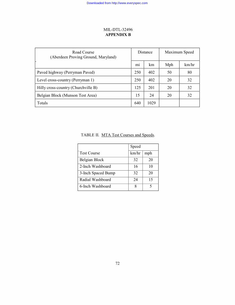
MIL-DTL-32496 APPENDIX B
72
Road Course (Aberdeen Proving Ground, Maryland)
Distance Maximum Speed
mi km Mph km/hr
Paved highway (Perryman Paved) 250 402 50 80
Level cross-country (Perryman 1) 250 402 20 32
Hilly cross-country (Churchville B) 125 201 20 32
Belgian Block (Munson Test Area) 15 24 20 32
Totals 640 1029
TABLE II. MTA Test Courses and Speeds.
Test Course
Speed km/hr mph
Belgian Block 32 20 2-Inch Washboard 16 10 3-Inch Spaced Bump 32 20 Radial Washboard 24 15 6-Inch Washboard 8 5
Downloaded from http://www.everyspec.com

MIL-DTL-32496 APPENDIX B
73
TEST METHOD 102.1
SAFETY AND HEALTH TEST
102.1.1 General. The generator sets and PU/PPs must not pose an unsafe or hazardous condition to personnel.
102.1.2 Apparatus. No specific equipment is required.
102.1.3 Procedure.
102.1.3.1 Preliminary safety and health assessment. A preliminary safety and health
assessment shall be accomplished upon receipt of the test units. This shall establish the safety of the units so that hazards to test participants can be minimized. As a minimum this preliminary assessment shall include the following essentials:
a. A thorough examination shall be conducted during the initial inspection and service test to
identify all obvious safety problems. Based on a visual examination of the units, the Safety Checklist (table III) shall be completed by the test director and, if available, a qualified safety engineer. At this point, based on the limited visual inspection, it is realized that only safety problems that are reasonably obvious shall be determined since a more thorough evaluation of safety and health shall be conducted during the remaining scope of testing. A cursory review of the safety and health warnings and other information shall be made of the equipment manuals provided. This is to assure that sufficient information has been provided in these manuals related to safety and health, specifically in the area of data plates, information, warning plates (including noise hazard warnings if required), proper grounding procedures, lifting and tie-down information, electrical shock hazard warnings, and other essential safety and health information that would ordinarily appear in a manual for a generator set. Some limited safety-related tasks shall be performed, if necessary, to ensure that the test items are safe for further testing.
b. During the initial inspection, an initial safety review shall be made using the safety
checklist contained in table III. The appropriate questions shall be answered insofar as possible without further testing. Detailed comments and answers shall be indicated for each applicable question of the safety checklists for electrical and mechanical hazards. Responses shall not be limited to only the items appearing on the checklist; any other safety and health hazards found shall be recorded and incorporated into this subtest.
102.1.3.2 Comprehensive safety and health assessment. A comprehensive safety and health
assessment shall be conducted throughout the entire test program. This assessment shall include:
a. Systematic observations and analysis of the test units throughout all phases of the entire test to identify and investigate any actual or potential hazards to personnel and equipment that may result from operation and maintenance. A detailed description of all safety hazards identified during operation, maintenance, and all other phases of operation shall be documented.
Downloaded from http://www.everyspec.com
MIL-DTL-32496 APPENDIX B
74
b. To ensure that the checklist of table III has been completed and that all hazards have been
identified, the test units shall be continuously monitored for hazards during all phases of testing and maintenance. It is expected that by the end of testing, all items on the safety checklist shall have been answered.
c. Limitations or compromises on operating performance and maintenance because of safety
considerations.
d. Examination of safety instructions and warning plates for adequacy and appropriate location.
e. Examination of operation and service manuals for adequate safety guidance concerning
operation and maintenance.
f. Classification of all safety hazards in accordance with MIL-STD-882 with recommendations for appropriate corrective measures and ways to either reduce or eliminate the hazard severity and hazard probability.
102.1.4 Results.
a. List all mechanical and electrical hazards. Identify all hazards that require warning
labels/placards.
b. Each NO answer reported in the checklist of table III and any other hazards identified shall be reviewed and assessed to determine the degree of noncompliance with the criteria. The hazard classification (including hazard severity and hazard probability) outlined in MIL-STD-882 shall be used to classify all identified safety hazards into hazard level categories. The hazards shall be categorized as a deficiency, shortcoming, or suggested improvement using table IV.
c. All problems recorded that have an effect on safety shall be thoroughly analyzed to
determine the extent of the problems and their impact on the operators, maintainers, and other personnel associated with the units. Noncompliance with specific elements of the criteria shall be evaluated and suggested corrective actions shall be proposed. Appropriate recommendations regarding methods to control, downgrade, or eliminate actual or potential hazards shall be made so that the necessary changes can be incorporated before field deployment.
Downloaded from http://www.everyspec.com
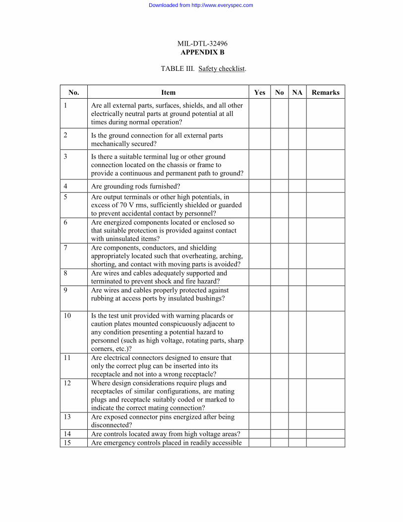
MIL-DTL-32496 APPENDIX B
TABLE III. Safety checklist.
No. Item Yes No NA Remarks
1 Are all external parts, surfaces, shields, and all other electrically neutral parts at ground potential at all times during normal operation?
2 Is the ground connection for all external parts mechanically secured?
3 Is there a suitable terminal lug or other ground connection located on the chassis or frame to provide a continuous and permanent path to ground?
4 Are grounding rods furnished?
5 Are output terminals or other high potentials, in excess of 70 V rms, sufficiently shielded or guarded to prevent accidental contact by personnel?
6 Are energized components located or enclosed so that suitable protection is provided against contact with uninsulated items?
7 Are components, conductors, and shielding appropriately located such that overheating, arching, shorting, and contact with moving parts is avoided?
8 Are wires and cables adequately supported and terminated to prevent shock and fire hazard?
9 Are wires and cables properly protected against rubbing at access ports by insulated bushings?
10 Is the test unit provided with warning placards or caution plates mounted conspicuously adjacent to any condition presenting a potential hazard to personnel (such as high voltage, rotating parts, sharp corners, etc.)?
11 Are electrical connectors designed to ensure that only the correct plug can be inserted into its receptacle and not into a wrong receptacle?
12 Where design considerations require plugs and receptacles of similar configurations, are mating plugs and receptacle suitably coded or marked to indicate the correct mating connection?
13 Are exposed connector pins energized after being disconnected?
14 Are controls located away from high voltage areas? 15 Are emergency controls placed in readily accessible
Downloaded from http://www.everyspec.com
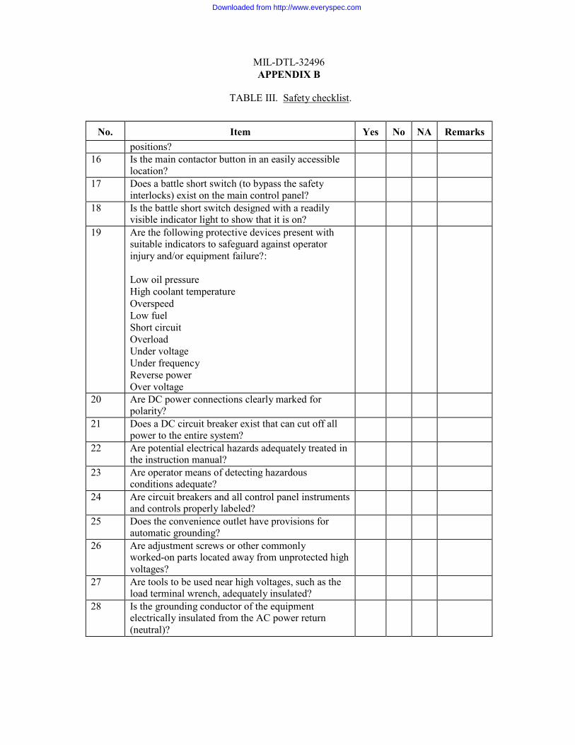
MIL-DTL-32496 APPENDIX B
TABLE III. Safety checklist.
No. Item Yes No NA Remarks positions? 16 Is the main contactor button in an easily accessible
location?
17 Does a battle short switch (to bypass the safety interlocks) exist on the main control panel?
18 Is the battle short switch designed with a readily visible indicator light to show that it is on?
19 Are the following protective devices present with suitable indicators to safeguard against operator injury and/or equipment failure?:
Low oil pressure High coolant temperature Overspeed Low fuel Short circuit Overload Under voltage Under frequency Reverse power Over voltage
20 Are DC power connections clearly marked for polarity?
21 Does a DC circuit breaker exist that can cut off all power to the entire system?
22 Are potential electrical hazards adequately treated in the instruction manual?
23 Are operator means of detecting hazardous conditions adequate?
24 Are circuit breakers and all control panel instruments and controls properly labeled?
25 Does the convenience outlet have provisions for automatic grounding?
26 Are adjustment screws or other commonly worked-on parts located away from unprotected high voltages?
27 Are tools to be used near high voltages, such as the load terminal wrench, adequately insulated?
28 Is the grounding conductor of the equipment electrically insulated from the AC power return (neutral)?
Downloaded from http://www.everyspec.com
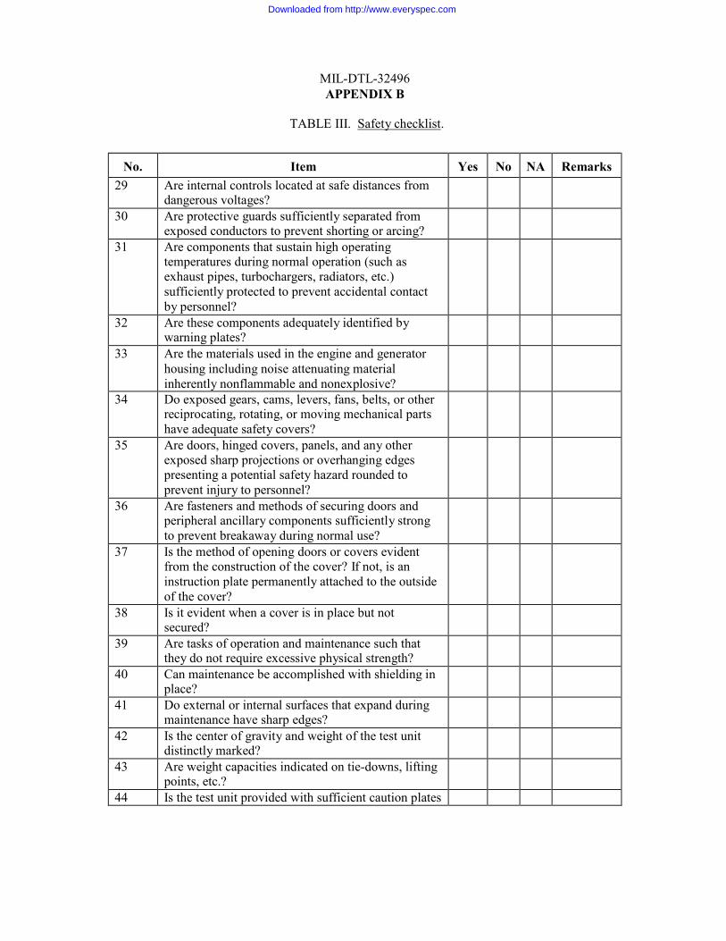
MIL-DTL-32496 APPENDIX B
TABLE III. Safety checklist.
No. Item Yes No NA Remarks 29 Are internal controls located at safe distances from
dangerous voltages?
30 Are protective guards sufficiently separated from exposed conductors to prevent shorting or arcing?
31 Are components that sustain high operating temperatures during normal operation (such as exhaust pipes, turbochargers, radiators, etc.) sufficiently protected to prevent accidental contact by personnel?
32 Are these components adequately identified by warning plates?
33 Are the materials used in the engine and generator housing including noise attenuating material inherently nonflammable and nonexplosive?
34 Do exposed gears, cams, levers, fans, belts, or other reciprocating, rotating, or moving mechanical parts have adequate safety covers?
35 Are doors, hinged covers, panels, and any other exposed sharp projections or overhanging edges presenting a potential safety hazard rounded to prevent injury to personnel?
36 Are fasteners and methods of securing doors and peripheral ancillary components sufficiently strong to prevent breakaway during normal use?
37 Is the method of opening doors or covers evident from the construction of the cover? If not, is an instruction plate permanently attached to the outside of the cover?
38 Is it evident when a cover is in place but not secured?
39 Are tasks of operation and maintenance such that they do not require excessive physical strength?
40 Can maintenance be accomplished with shielding in place?
41 Do external or internal surfaces that expand during maintenance have sharp edges?
42 Is the center of gravity and weight of the test unit distinctly marked?
43 Are weight capacities indicated on tie-downs, lifting points, etc.?
44 Is the test unit provided with sufficient caution plates
Downloaded from http://www.everyspec.com
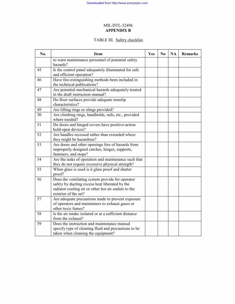
MIL-DTL-32496 APPENDIX B
TABLE III. Safety checklist.
No. Item Yes No NA Remarks to warn maintenance personnel of potential safety
hazards?
45 Is the control panel adequately illuminated for safe and efficient operation?
46 Have fire-extinguishing methods been included in the technical publications?
47 Are potential mechanical hazards adequately treated in the draft instruction manual?
48 Do floor surfaces provide adequate nonslip characteristics?
49 Are lifting rings or slings provided? 50 Are climbing rings, handholds, rails, etc., provided
where needed?
51 Do doors and hinged covers have positive-action hold-open devices?
52 Are handles recessed rather than extended where they might be hazardous?
53 Are doors and other openings free of hazards from improperly designed catches, hinges, supports, fasteners, and stops?
54 Are the tasks of operation and maintenance such that they do not require excessive physical strength?
55 When glass is used is it glare proof and shatter proof?
56 Does the ventilating system provide for operator safety by ducting excess heat liberated by the radiator cooling air or other hot air outlets to the exterior of the set?
57 Are adequate precautions made to prevent exposure of operators and maintainers to exhaust gases or other toxic fumes?
58 Is the air intake isolated or at a sufficient distance from the exhaust?
59 Does the instruction and maintenance manual specify type of cleaning fluid and precautions to be taken when cleaning the equipment?
Downloaded from http://www.everyspec.com
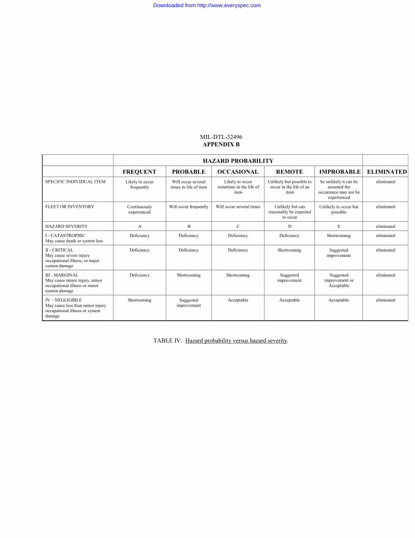
HAZARD PROBABILITY
FREQUENT PROBABLE OCCASIONAL REMOTE IMPROBABLE ELIMINATED SPECIFIC INDIVIDUAL ITEM Likely to occur
frequently Will occur several
times in life of item Likely to occur
sometime in the life of item
Unlikely but possible to occur in the life of an
item
So unlikely it can be assumed the
occurrence may not be experienced
eliminated
FLEET OR INVENTORY Continuously experienced
Will occur frequently Will occur several times Unlikely but can reasonably be expected
to occur
Unlikely to occur but possible
eliminated
HAZARD SEVERITY A B C D E eliminated
I - CATASTROPHIC May cause death or system loss
Deficiency Deficiency Deficiency Deficiency Shortcoming eliminated
II - CRITICAL May cause severe injury occupational illness, or major system damage
Deficiency Deficiency Deficiency Shortcoming Suggested improvement
eliminated
III - MARGINAL May cause minor injury, minor occupational illness or minor system damage
Deficiency Shortcoming Shortcoming Suggested improvement
Suggested improvement or
Acceptable
eliminated
IV – NEGLIGIBLE May cause less than minor injury occupational illness or system damage
Shortcoming Suggested improvement
Acceptable Acceptable Acceptable eliminated
MIL-DTL-32496 APPENDIX B
TABLE IV. Hazard probability versus hazard severity.
Downloaded from http://www.everyspec.com
MIL-DTL-32496 APPENDIX B
TEST METHOD 103.1
HUMAN FACTORS ENGINEERING TEST
103.1.1 General. The generator sets and PU/PPs must satisfy general human engineering design criteria and practices.
103.1.2 Apparatus. The following equipment shall be required: photographic and video
equipment, tape measure, ruler, and illumination meter (lighted displays).
103.1.3 Procedure.
103.1.3.1 Control, display, labeling. Observations shall be made of all controls, displays, and labeling with respect to HFE design practices (based on paragraphs 5.1, 5.2, 5.4, and 5.5 of MIL-STD-1472). Control separation and control dimensional measurements shall be taken to determine if any design problems exist. The ability of the operator to successfully operate the sets while wearing regular, arctic, and NBC gloves shall be observed as well as the operator's ability to operate the set at night.
103.1.3.2 Workspace and maintenance access. Maintenance access openings and workspaces
shall be observed with respect to the ability of the crew to perform maintenance and to determine compatibility with anthropometrical dimensions for the 5th through 95th percentile personnel while outfitted in battle dress uniform (BDU), arctic, and NBC protective ensembles.
103.1.3.3 Subjective assessment.
a. Questionnaires/interviews. Human factors questionnaires shall be administered to
personnel assigned to the testing program. Questionnaires shall primarily pertain to operating and maintaining the equipment. A section of each questionnaire shall be devoted to task performance while wearing nuclear, biological, chemical (NBC) and arctic gear. Questionnaires, (table 103.1-B), shall be administered near the end of the test cycle to assure that all personnel are thoroughly experienced with system operations before completing the forms. Interviews shall be conducted to determine the test participant's opinions on the overall operation, maintenance, and performance of the generator.
b. Checklists. Checklists (table 103.1-C) shall be prepared by an HFE engineer on the
following elements of system design:
1. HFE design - controls, displays, and markings.
2. Maintainability.
c. General HFE observations. Observations shall be made throughout all testing to gain additional information on any HFE-related problems. Comments and informal interviews, in addition to HFE observations, shall be documented throughout to provide subjective input to assess the AMMPS sets and PU/PPs. These interviews, comments, and observations shall be used to augment data from other HFE subtests supplements and shall be integrated into the analysis of the AMMPS sets and PU/PPs.
Downloaded from http://www.everyspec.com
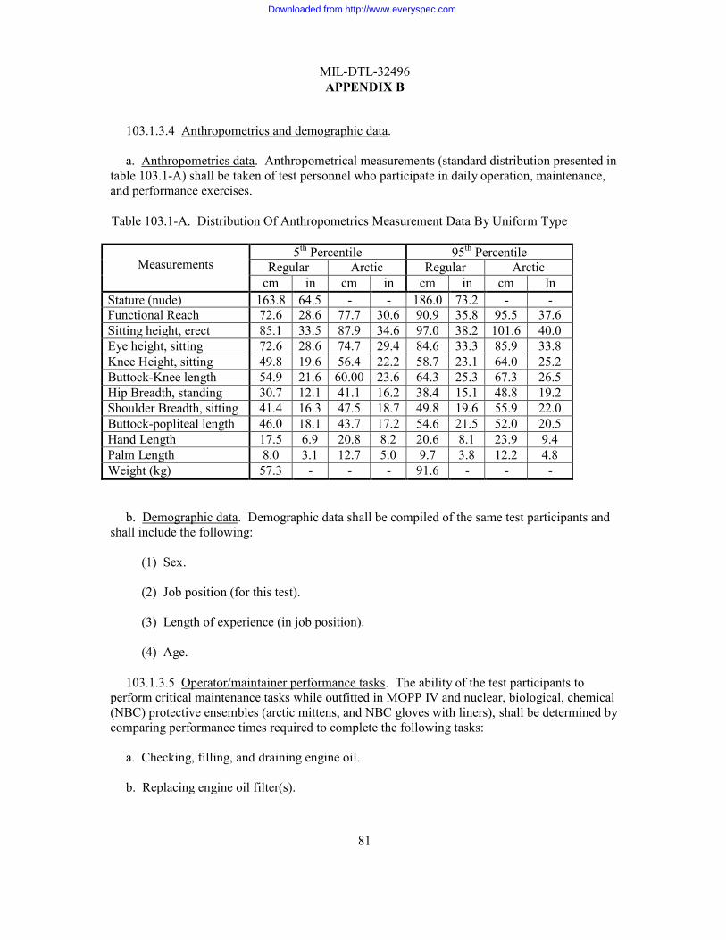
MIL-DTL-32496 APPENDIX B
81
103.1.3.4 Anthropometrics and demographic data.
a. Anthropometrics data. Anthropometrical measurements (standard distribution presented in table 103.1-A) shall be taken of test personnel who participate in daily operation, maintenance, and performance exercises.
Table 103.1-A. Distribution Of Anthropometrics Measurement Data By Uniform Type
Measurements 5th Percentile 95th Percentile
Regular Arctic Regular Arctic cm in cm in cm in cm In
Stature (nude) 163.8 64.5 - - 186.0 73.2 - - Functional Reach 72.6 28.6 77.7 30.6 90.9 35.8 95.5 37.6 Sitting height, erect 85.1 33.5 87.9 34.6 97.0 38.2 101.6 40.0 Eye height, sitting 72.6 28.6 74.7 29.4 84.6 33.3 85.9 33.8 Knee Height, sitting 49.8 19.6 56.4 22.2 58.7 23.1 64.0 25.2 Buttock-Knee length 54.9 21.6 60.00 23.6 64.3 25.3 67.3 26.5 Hip Breadth, standing 30.7 12.1 41.1 16.2 38.4 15.1 48.8 19.2 Shoulder Breadth, sitting 41.4 16.3 47.5 18.7 49.8 19.6 55.9 22.0 Buttock-popliteal length 46.0 18.1 43.7 17.2 54.6 21.5 52.0 20.5 Hand Length 17.5 6.9 20.8 8.2 20.6 8.1 23.9 9.4 Palm Length 8.0 3.1 12.7 5.0 9.7 3.8 12.2 4.8 Weight (kg) 57.3 - - - 91.6 - - -
b. Demographic data. Demographic data shall be compiled of the same test participants and shall include the following:
(1) Sex.
(2) Job position (for this test).
(3) Length of experience (in job position).
(4) Age.
103.1.3.5 Operator/maintainer performance tasks. The ability of the test participants to perform critical maintenance tasks while outfitted in MOPP IV and nuclear, biological, chemical (NBC) protective ensembles (arctic mittens, and NBC gloves with liners), shall be determined by comparing performance times required to complete the following tasks:
a. Checking, filling, and draining engine oil.
b. Replacing engine oil filter(s).
Downloaded from http://www.everyspec.com

MIL-DTL-32496 APPENDIX B
82
c. Replacing air filter element.
d. Connecting load cable.
e. Replacing fuel filter(s).
f. Checking, filling, and draining hydraulic fluid (if equipped).
g. Replacing hydraulic fluid filter(s) (if equipped).
h. Other common field maintenance actions such as filling fuel tank, radiator, battery, and adjusting belts, etc.
Excessive maintenance times or inability to perform any critical maintenance tasks shall be recorded.
103.1.3.6 Manual readability. The reading grade level (RGL) of the operation and
maintenance manual shall be determined by conducting a readability test as referenced in TOP 1-2-609, Instructional Material Adequacy Guide and Evaluation Standard (Images), January 1981. An adequate number of text samples shall be used to determine the overall grade level (OGL).
103.1.3.7 Data required. The following data shall be obtained.
a. Control separation and dimensional measurements.
b. Ability of operators to operate the sets while wearing regular, arctic, and NBC gear.
c. Anthropometric and demographic data of test participants.
d. Results of interview and questionnaires administered to test personnel.
e. Results of completed checklists.
f. An assessment of controls and displays.
g. The adequacy of New Equipment Training (NET).
h. RGL of the operation and maintenance manuals.
i. Photographs and videotapes of HFE problems associated with the setup, operation, or maintenance of the generator sets.
j. Performance times of critical maintenance tasks while maintainers are outfitted in arctic
and NBC ensembles.
103.1.4 Results.
Downloaded from http://www.everyspec.com
MIL-DTL-32496 APPENDIX B
83
a. Qualitative results of observations, checklists and questionnaires shall be summarized and presented in narrative and tabular form.
b. The degree to which the generators conform or do not conform to HFE standards and
requirements shall be presented. Instances of nonconformance shall be supported by measurements and photographic illustrations. The causes and consequences of nonconformance shall be assessed with regard to the effect on mission performance. Any degradation of the systems’ man-item relationship with regard to safety shall be assessed and corrective action recommended. Human performance reliability shall be assessed in terms of frequency and consequence of human error committed during preparation, operation, and maintenance of the generators. Subjective data analysis shall include a structured interview follow-up of all unfavorable/negative comments to arrive at a description of the cause and possible corrective action.
c. The following shall constitute failure of this test:
(1) Controls, displays, or labeling that do not conform to MIL-STD-1472, paragraphs 5.2,
5.4, and 5.5 in relation to appearance, spacing, size, or location.
(2) Inability to successfully operate or maintain the sets when personnel are wearing regular, NBC, or MOPP IV gear.
(3) Workspace and maintenance access openings that do not allow personnel, with
anthropometrical dimensions between the 5th through the 95th percentile, to perform maintenance.
Downloaded from http://www.everyspec.com
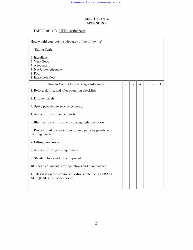
MIL-DTL-32496 APPENDIX B
84
TABLE 103.1-B. HFE questionnaire.
How would you rate the adequacy of the following?
Rating Scale 6 Excellent 5 Very Good 4 Adequate 3 Not Quite Adequate 2 Poor 1 Extremely Poor
Human Factors Engineering - Adequacy 6 5 4 3 2 1
1. Before, during, and after operation checklist. 2. Display panels.
3. Space provided to service generator.
4. Accessibility of hand controls.
5. Illumination of instruments during night operation.
6. Protection of operator from moving parts by guards and warning panels.
7. Lifting provisions.
8. Access for using test equipment.
9. Standard tools and test equipment.
10. Technical manuals for operations and maintenance.
11. Based upon the previous questions, rate the OVERALL ADEQUACY of the generator.
Downloaded from http://www.everyspec.com
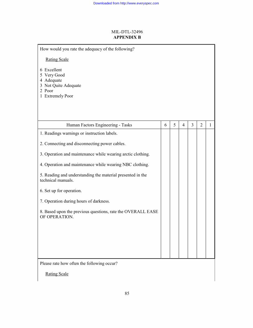
85
MIL-DTL-32496 APPENDIX B
How would you rate the adequacy of the following?
Rating Scale 6 Excellent 5 Very Good 4 Adequate 3 Not Quite Adequate 2 Poor 1 Extremely Poor
Human Factors Engineering - Tasks 6 5 4 3 2 1
1. Readings warnings or instruction labels. 2. Connecting and disconnecting power cables.
3. Operation and maintenance while wearing arctic clothing.
4. Operation and maintenance while wearing NBC clothing.
5. Reading and understanding the material presented in the technical manuals.
6. Set up for operation.
7. Operation during hours of darkness.
8. Based upon the previous questions, rate the OVERALL EASE OF OPERATION.
Please rate how often the following occur?
Rating Scale
Downloaded from http://www.everyspec.com
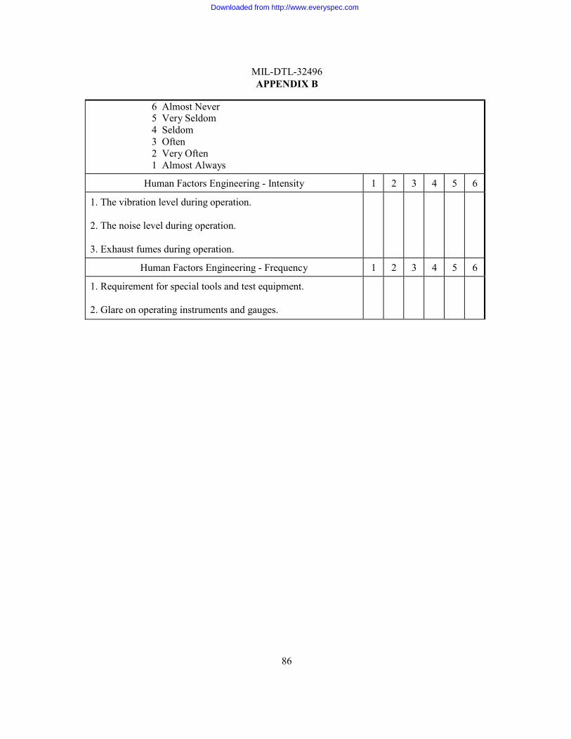
86
MIL-DTL-32496 APPENDIX B
6 Almost Never 5 Very Seldom 4 Seldom 3 Often 2 Very Often 1 Almost Always
Human Factors Engineering - Intensity 1 2 3 4 5 6
1. The vibration level during operation. 2. The noise level during operation.
3. Exhaust fumes during operation.
Human Factors Engineering - Frequency 1 2 3 4 5 6
1. Requirement for special tools and test equipment. 2. Glare on operating instruments and gauges.
Downloaded from http://www.everyspec.com
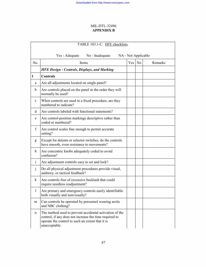
MIL-DTL-32496 APPENDIX B
87
TABLE 103.1-C. HFE checklists.
Yes - Adequate No - Inadequate NA - Not Applicable
No. Items Yes No Remarks HFE Design - Controls, Displays, and Marking
1 Controls
a Are all adjustments located on single panel?
b Are controls placed on the panel in the order they will normally be used?
c When controls are used in a fixed procedure, are they numbered to indicate?
d Are controls labeled with functional statements?
e Are control-position markings descriptive rather than coded or numbered?
f Are control scales fine enough to permit accurate setting?
g Except for detents or selector switches, do the controls have smooth, even resistance to movements?
h Are concentric knobs adequately coded to avoid confusion?
i Are adjustment controls easy to set and lock?
j Do all physical adjustment procedures provide visual, auditory, or tactical feedback?
k Are controls free of excessive backlash that could require needless readjustment?
l Are primary and emergency controls easily identifiable both visually and nonvisually?
m Can controls be operated by personnel wearing arctic and NBC clothing?
n The method used to prevent accidental activation of the control, if any does not increase the time required to operate the control to such an extent that it is unacceptable.
Downloaded from http://www.everyspec.com
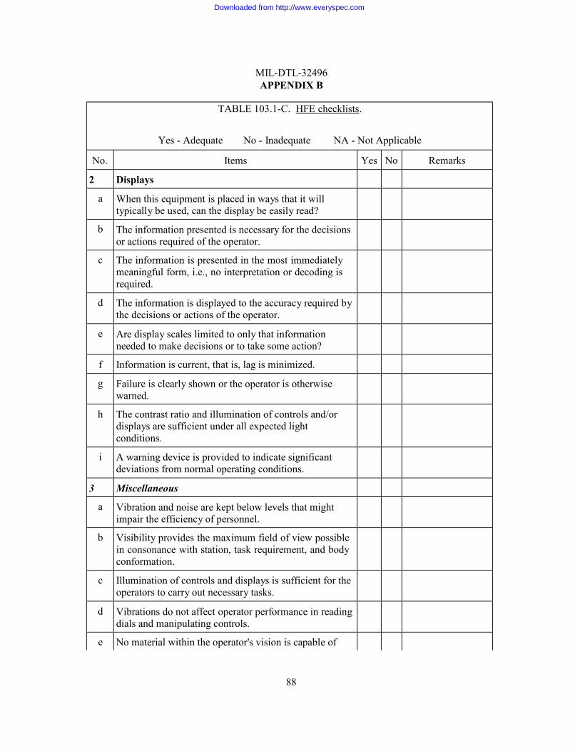
MIL-DTL-32496 APPENDIX B
88
TABLE 103.1-C. HFE checklists.
Yes - Adequate No - Inadequate NA - Not Applicable
No. Items Yes No Remarks
2 Displays
a When this equipment is placed in ways that it will typically be used, can the display be easily read?
b The information presented is necessary for the decisions or actions required of the operator.
c The information is presented in the most immediately meaningful form, i.e., no interpretation or decoding is required.
d The information is displayed to the accuracy required by the decisions or actions of the operator.
e Are display scales limited to only that information needed to make decisions or to take some action?
f Information is current, that is, lag is minimized.
g Failure is clearly shown or the operator is otherwise warned.
h The contrast ratio and illumination of controls and/or displays are sufficient under all expected light conditions.
i A warning device is provided to indicate significant deviations from normal operating conditions.
3 Miscellaneous
a Vibration and noise are kept below levels that might impair the efficiency of personnel.
b Visibility provides the maximum field of view possible in consonance with station, task requirement, and body conformation.
c Illumination of controls and displays is sufficient for the operators to carry out necessary tasks.
d Vibrations do not affect operator performance in reading dials and manipulating controls.
e No material within the operator's vision is capable of
Downloaded from http://www.everyspec.com
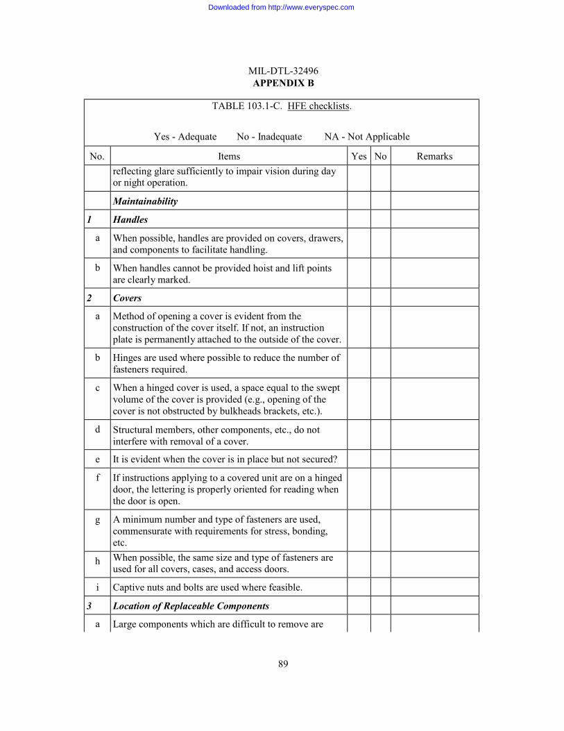
MIL-DTL-32496 APPENDIX B
89
TABLE 103.1-C. HFE checklists.
Yes - Adequate No - Inadequate NA - Not Applicable
No. Items Yes No Remarks reflecting glare sufficiently to impair vision during day
or night operation.
Maintainability
1 Handles
a When possible, handles are provided on covers, drawers, and components to facilitate handling.
b When handles cannot be provided hoist and lift points are clearly marked.
2 Covers
a Method of opening a cover is evident from the construction of the cover itself. If not, an instruction plate is permanently attached to the outside of the cover.
b Hinges are used where possible to reduce the number of fasteners required.
c When a hinged cover is used, a space equal to the swept volume of the cover is provided (e.g., opening of the cover is not obstructed by bulkheads brackets, etc.).
d Structural members, other components, etc., do not interfere with removal of a cover.
e It is evident when the cover is in place but not secured?
f If instructions applying to a covered unit are on a hinged door, the lettering is properly oriented for reading when the door is open.
g A minimum number and type of fasteners are used, commensurate with requirements for stress, bonding, etc.
h When possible, the same size and type of fasteners are used for all covers, cases, and access doors.
i Captive nuts and bolts are used where feasible.
3 Location of Replaceable Components
a Large components which are difficult to remove are
Downloaded from http://www.everyspec.com
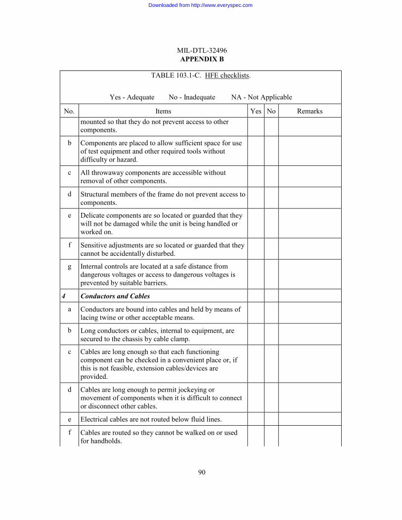
MIL-DTL-32496 APPENDIX B
90
TABLE 103.1-C. HFE checklists.
Yes - Adequate No - Inadequate NA - Not Applicable
No. Items Yes No Remarks mounted so that they do not prevent access to other
components.
b Components are placed to allow sufficient space for use of test equipment and other required tools without difficulty or hazard.
c All throwaway components are accessible without removal of other components.
d Structural members of the frame do not prevent access to components.
e Delicate components are so located or guarded that they will not be damaged while the unit is being handled or worked on.
f Sensitive adjustments are so located or guarded that they cannot be accidentally disturbed.
g Internal controls are located at a safe distance from dangerous voltages or access to dangerous voltages is prevented by suitable barriers.
4 Conductors and Cables
a Conductors are bound into cables and held by means of lacing twine or other acceptable means.
b Long conductors or cables, internal to equipment, are secured to the chassis by cable clamp.
c Cables are long enough so that each functioning component can be checked in a convenient place or, if this is not feasible, extension cables/devices are provided.
d Cables are long enough to permit jockeying or movement of components when it is difficult to connect or disconnect other cables.
e Electrical cables are not routed below fluid lines.
f Cables are routed so they cannot be walked on or used for handholds.
Downloaded from http://www.everyspec.com
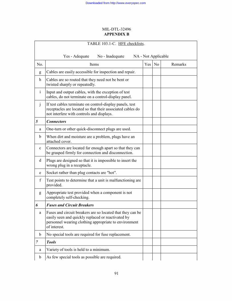
MIL-DTL-32496 APPENDIX B
91
TABLE 103.1-C. HFE checklists.
Yes - Adequate No - Inadequate NA - Not Applicable
No. Items Yes No Remarks
g Cables are easily accessible for inspection and repair.
h Cables are so routed that they need not be bent or twisted sharply or repeatedly.
i Input and output cables, with the exception of test cables, do not terminate on a control-display panel.
j If test cables terminate on control-display panels, test receptacles are located so that their associated cables do not interfere with controls and displays.
5 Connectors
a One-turn or other quick-disconnect plugs are used.
b When dirt and moisture are a problem, plugs have an attached cover.
c Connectors are located far enough apart so that they can be grasped firmly for connection and disconnection.
d Plugs are designed so that it is impossible to insert the wrong plug in a receptacle.
e Socket rather than plug contacts are "hot".
f Test points to determine that a unit is malfunctioning are provided.
g Appropriate test provided when a component is not completely self-checking.
6 Fuses and Circuit Breakers
a Fuses and circuit breakers are so located that they can be easily seen and quickly replaced or reactivated by personnel wearing clothing appropriate to environment of interest.
b No special tools are required for fuse replacement.
7 Tools
a Variety of tools is held to a minimum.
b As few special tools as possible are required.
Downloaded from http://www.everyspec.com
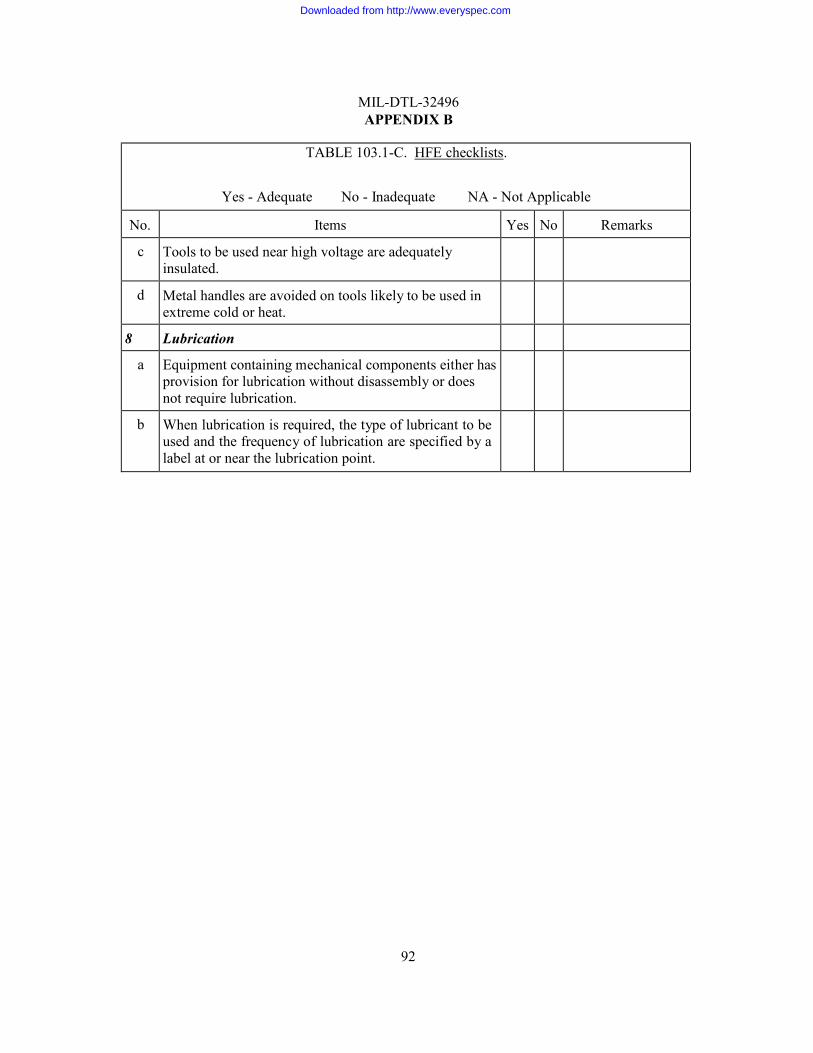
MIL-DTL-32496 APPENDIX B
92
TABLE 103.1-C. HFE checklists.
Yes - Adequate No - Inadequate NA - Not Applicable
No. Items Yes No Remarks
c Tools to be used near high voltage are adequately insulated.
d Metal handles are avoided on tools likely to be used in extreme cold or heat.
8 Lubrication
a Equipment containing mechanical components either has provision for lubrication without disassembly or does not require lubrication.
b When lubrication is required, the type of lubricant to be used and the frequency of lubrication are specified by a label at or near the lubrication point.
Downloaded from http://www.everyspec.com
93
MIL-DTL-32496
Concluding Material
Custodian: Preparing Activity:
Army - CR4 Army - CR4
(Project 6115- 2014-001)
Review Activities:
DLA – GS
Note: The activities listed above were interested in this document as of the date of this document. Since organization and responsibilities can change, you should verify the currency of the information above using ASSIST Online at https://assist.dla.mil.
Downloaded from http://www.everyspec.com